Jbl Car Amplifier A3000Gti Users Manual 20377_A6000_GTi Amp_Eng
A3000GTI to the manual a90a8cf4-8680-4157-a705-e3fbf8c281ae
2015-02-04
: Jbl Jbl-Jbl-Car-Amplifier-A3000Gti-Users-Manual-369250 jbl-jbl-car-amplifier-a3000gti-users-manual-369250 jbl pdf
Open the PDF directly: View PDF ![]() .
.
Page Count: 12

car audio
power amplifier
owner’s manual
THANK YOU
for purchasing a JBL A6000GTi or A3000GTi amplifier.
For warranty support, please register your purchase at www.jbl.com.
Select Car Audio, then click on Support, and then click on Product Registration.
Also, please retain your original purchase receipt and packing crate
in case you must ship your unit back for service.

INSTALLATION
WARNING: Playing loud music
in an automobile can hinder your
ability to hear traffic and permanently
damage your hearing. We recommend
listening at low or moderate levels
while driving your car. JBL accepts
no liability for hearing loss, bodily injury
or property damage resulting from the
use or misuse of this product.
IMPORTANT: To get the best
performance from your JBL A6000GTi or
A3000GTi amplifier, we strongly
recommend that installation be entrust-
ed to a qualified professional. Although
these instructions explain how to install
JBL amplifiers in a
general sense, they do not show
specific installation methods that may
be required for your particular vehicle.
If you do not have the necessary tools
or experience, do not attempt the
installation yourself. Instead, please ask
your authorized JBL car audio dealer
about professional installation.
INSTALLATION
WARNINGS AND TIPS
• Always wear protective eyewear
when using tools.
• Turn off all audio components and
other electrical devices before you
start. Disconnect the (–) negative lead
from your vehicle’s battery.
• Check clearances on both sides of
a planned mounting surface before
drilling holes or installing screws.
Remember – the screws can extend
behind the surface.
• At the installation sites, locate
and make a note of all fuel lines,
hydraulic brake lines, vacuum lines,
and electrical wiring. Use extreme
caution when cutting or drilling in and
around these areas.
• Before drilling or cutting holes, use
a utility knife to remove unwanted
fabric or vinyl to keep material from
snagging in a drill bit.
• When routing cables, keep input-
signal cables away from power
cables and speaker wires. Use
grommets when passing cables
through the vehicle’s inner walls.
• When making connections, observe
the amplifier’s polarity markings.
Make sure that each connection
is clean and properly secured. Use
the shortest ground wire possible
to minimize resistance and avoid
noise problems.
• If the amplifier’s fuse must be
replaced, use only the same type
and rating as that of the original.
Do not substitute another kind.
CHOOSING A
MOUNTING LOCATION
The JBL A6000GTi and A3000GTi
amplifiers are big! Conventional mount-
ing locations under driver or passenger
seats will not accommodate either
amplifier. Mount the amplifier in the
vehicle’s trunk or cargo area, but never
mount the amplifier in the engine com-
partment, outside the vehicle or
in any location where it may get wet.
When choosing a location, make sure
the site’s underlying structure is strong
enough to support the amplifier’s
weight and drilled holes for mounting
bolts. Also, verify that there will be ade-
quate ventilation around the amplifier,
so that airflow to its internal fans will
not be blocked and the unit can
properly cool itself.
WARNING: To avoid personal injury and
possible product damage, we strongly
urge you to enlist additional help in
unpacking and moving the
JBL A6000GTi or A3000GTi amplifier
to a desired mounting location.
PARTS LIST
Each amplifier is packed with the fol-
lowing parts:
• Four (4) 1/2" x 3" socket-head cap
screws and T-nuts.
• One (1) Remote Level Control with
mounting hardware
• One (1) 15' RJ11 Cable for Remote
Level Control
• One (1) Logo Badge
• One (1) Set of Performance Graphs
• One (1) Owner’s Manual
• One (1) Warranty Registration
Instruction Card
MOUNTING THE
AMPLIFIER
We strongly recommend first mounting
a piece of wood or Medium Density
Fiberboard (MDF) to the vehicle, and
then mounting the amplifier to the
board. The amplifier is large and heavy
and must be mounted using all four
screws and T-nuts provided. Using
the amplifier as a template, mark the
location of the mounting holes on the
mounting surface, drill pilot holes, and
securely attach the amplifier to the
mounting surface with the provided
screws and T-nuts. Make sure the
amplifier does not pinch or smash
power cables, speaker wires, input
cables or any of the vehicle’s wiring.
Install the Remote Level Control in a
convenient location in or under the
dashboard. The control may be
removed from its housing for custom
installation. Using the enclosed RJ11
cable, connect the control to the
amplifier, as shown in Figure 1.
2
A6000GTi/A3000GTi
(on input panel)
RJ11 Cable
RJ45 connector
RJ45 connector on back
Figure 1. Connecting the Remote Level
Control.
Once the amplifier is mounted, peel the
backing from the adhesive (on the back
of the logo badge) and attach the badge
in the appropriate orientation.

DESIGNING A SPEAKER SYSTEM FOR THE GTI AMPLIFIER
NOTE: Although the JBL A6000GTi or
A3000GTi amplifier will drive a system
made up of any subwoofers, we
recommend using JBL GTi subwoofers
with GTi amplifiers.
Both the JBL A6000GTi and A3000GTi
amplifiers provide RMS power that
exceeds the RMS power-handling
rating of nearly every subwoofer
available. To use this amplifier
optimally, you should design a speaker
system made up of several identical
speakers, so that the power delivered
by the amplifier will be shared equally
among the speakers.
The JBL A6000GTi and A3000GTi
amplifiers support a wide range of
impedances, and any speaker system
with a total or equivalent impedance of
1 to 4 ohms will extract full power from
either amplifier. In order to connect
multiple woofers to the A6000GTi or
A3000GTi, you’ll need to connect your
speakers in series, parallel or series-
parallel. We’ve included diagrams for
each connection scheme and a pair of
formulas, which will help you.
SERIES CONNECTIONS
The formula for determining the total
impedance of the two woofers connect-
ed in series is:
Ztotal = Z1+ Z2+ Z3...
Where Ztotal is the total impedance of
all woofers connected in series. Z1, Z2
and Z3(and so on) are the nominal
impedance ratings of the individual
speakers. The total impedance of the
voice coils shown in Figure 2 is 8 ohms.
Figure 2. Series connection of two
4-ohm voice coils yields a total
impedance of 8 ohms.
PARALLEL CONNECTIONS
The formula for determining the
equivalent impedance of the voice coils
connected in parallel is:
Zequivalent = 1/(1/Z1+ 1/Z2+ 1/Z3…)
Where Zequivalent is the equivalent
impedance of the coils connected in
parallel. Z1, Z2and Z3(and so on) are
the nominal impedance ratings of the
individual speakers. The equivalent
impedance of the voice coils shown in
Figure 3 is 2 ohms.
Figure 3. Parallel connection of two
4-ohm voice coils yields a total
impedance of 2 ohms.
DUAL VOICE-COIL
CONNECTIONS
Dual voice-coil subwoofers, such as
JBL’s GTi series, may be connected
in series, as shown in Figure 2;
in parallel, as shown in Figure 3; or in
series-parallel, as shown in Figure 4.
Figure 4. Series-parallel connections
of three W15GTi subwoofers (with a
voice coil impedance of 6 ohms) yields
a total series impedance of 12 ohms
for each subwoofer, and an equivalent
parallel impedance of 4 ohms for all
three subwoofers.
To determine the impedance of a
system of three W15GTi (dual voice-
coil) subwoofers connected in series-
parallel, use the series connection
formula to determine the impedance
of each subwoofer with its voice coils
connected in series. Then insert the
calculated value into the parallel
connection formula to determine the
equivalent impedance for the three sub-
woofers connected in parallel.
NOTE: Each W15GTi voice coil has an
impedance of 6 ohms.
For example, in Figure 4, each woofer
will have an impedance of 12 ohms, by
Ztotal = Z1+ Z2= 6 + 6 = 12
and the three woofers connected
in parallel will have an equivalent
impedance of 4 ohms, by
Zequivalent = 1/(1/Z1+ 1/Z2+ 1/Z3)
= 1/(1/12 + 1/12 + 1/12)
= 1/(3/12)
= 12/3 = 4
NOTE: All subwoofers connected to an
amplifier in a system must be identical
and, if they are dual voice-coil sub-
woofers, their coils must be wired iden-
tically. Do not connect the coils of one
subwoofer together in series and
another in parallel, since doing so will
cause uneven power distribution,
potential damage to the speakers, and
poor overall performance.
ABOUT SPEAKER
POWER HANDLING
The RMS power handling rating of
a speaker indicates the amount of
power it will handle continuously.
Although designing a subwoofer
system by considering the RMS rating
will ultimately provide you with the
most reliable system, your speakers
may be able to handle more power,
depending on what kind of music is
being reproduced.
For music with extended bass notes
(e.g., bass music, hip-hop or techno),
you should design a speaker system
based on the RMS power handling of
your speakers. For music with sharp
transient bass notes (e.g., rock,
country or jazz), the RMS power
handling rating is conservative, and you
can count on your speakers being able
to handle more power than the RMS
rating.
The total power output of your
amplifier will be divided among the
speakers connected to it. For example,
if you are using an A6000GTi and three
W15GTi subwoofers, each subwoofer
will receive 2,000 watts.
It’s important to choose a system of
subwoofers that will handle all of the
power. To determine how much total
power your speaker system will
handle, simply multiply the RMS power
handling rating of one of your speakers
by the total number of speakers that
will be connected.
3
4 ohms 4 ohms
Remove
Terminal Jumper
Remove
Terminal Jumper
Black
Red
4 ohms 4 ohms

4
SUPPLYING POWER TO THE GTI AMPLIFIER
POWER IN IS
POWER OUT
In order to get full power out of your
amplifier, you must provide full power to
your amplifier. That’s a basic rule
of physics. The A6000GTi amplifier
can draw nearly 800 amperes when
reproducing sine waves at full output.
Both JBL A6000GTi and A3000GTi ampli-
fiers can quickly exhaust the
factory-installed charging system of
any vehicle on the road today. With this
much available amplifier power, you will
need to beef up your vehicle’s
electrical system to satisfy the
amplifier’s current demands. We
recommend adding at least two
12-volt batteries, connected in
parallel with cold-cranking capacities
of at least 600 amperes each, to the
factory-installed charging system.
HOW YOUR CHARGING
SYSTEM WORKS
The battery’s job is to start your
vehicle. Running the electrical
accessories is the alternator’s job.
The battery isn’t designed to be a
continuous source of power. It is a
renewable source and is charged by
the alternator when the engine runs.
Battery charging can only occur when
the current demand from the electrical
accessories is less than the total cur-
rent output capacity of the alternator.
PROGRAM MATERIAL
AND CURRENT DEMAND
Music is a combination of loud and
soft sounds, with varying durations
and rhythms that present unique
current demands during amplification.
For example, it may take full power
to reproduce the sound of a kick
drum. The peak power demand doesn’t
last very long, but it is repeated over
and over.
If your charging system can’t provide all
the power your amplifier needs on
a continuous basis, it still may be
adequate. During the sound of the
kick drum, the battery can provide
the extra current that’s necessary,
and between kick drum beats, the alter-
nator will put some of the energy back
into the battery.
However, depending on the current rat-
ing of the alternator, the amplifier’s
maximum output power, the music
content, and the charging system’s
capability, the alternator may not be
able to keep up over time. In that case,
you’ll need to install a somewhat larger
alternator for more current, or adjust
your driving and listening habits, to give
the alternator time to catch up with the
amplifier’s current demand.
Few stock batteries can provide the
current required to reproduce even
short-duration musical peaks. Adding
a pair of batteries with cold-cranking
capacities of 600 amperes will provide
extra current for short music bursts, but
reserve power may still be
depleted over longer music intervals.
Adding more batteries will provide more
reserve power and current, but no mat-
ter how many are installed, the alterna-
tor will still have to recharge them all.
If you plan to use the A6000GTi or
A3000GTi in SPL competition, the charg-
ing system requirements will be much
greater than those for normal music lis-
tening. Be prepared to add additional
batteries and alternators to provide
continuous current required for contin-
uous duty.
See your authorized JBL car audio
dealer for help in designing and
installing an upgraded charging
system to support your GTi amplifier.
5
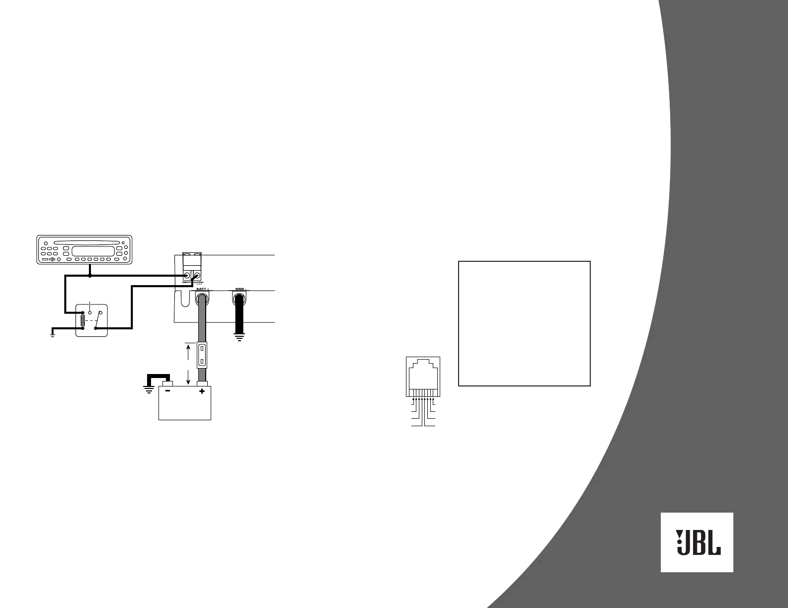
MAKING THE CONNECTIONS
POWER CONNECTIONS
Use 0-gauge cable to connect the
amplifier’s GND – terminal directly to
the vehicle’s chassis (see Figure 5).
Scrape off all paint from the metal area
for a good, clean ground connection.
Make sure the ground wire is as short
as possible and is connected to metal
on the vehicle’s body. Do not connect
the GND – cable to the frame of the
vehicle. It is isolated from the chassis
using rubber shims and will not provide
an adequate ground. Instead, use the
trunk’s floor or cargo area as a suitable
location. Do not connect the GND –
cable to the battery’s negative (–)
terminal.
Figure 5. Power wiring
diagram for the JBL A6000GTi
amplifier. The A3000GTi is
wired in a similar way.
Use 0-gauge cable to connect the
BATT+ terminal directly to the vehicle’s
battery. If the battery is located in the
engine compartment and the BATT+
cable must be routed through the
firewall or any metal obstruction, install
a wafer-type (ANN) fuse with a current
rating of at least 500 amperes and an
appropriate fuse holder
within 18" of the vehicle’s battery
(see Figure 5).
Connect the source unit’s remote
turn-on lead to the REMOTE terminal on
the amplifier (see Figure 5). Use
any convenient gauge wire for the
connection.
The amplifier’s internal neon lights
require a separate switched power
connection with at least a 2-ampere cur-
rent capacity. If desired, install a switch
to turn on the neon lights or a relay trig-
gered by a circuit in the vehicle (e.g.,
door switch, trunk pin switch or other
turn-on source). If you want the amplifi-
er’s neon to light when the
amplifier is on, connect the LIGHTING
terminal to a relay triggered by the radio’s
remote turn-on lead (see Figure 5).
IMPORTANT: Do not connect a jumper
directly between the REMOTE and
LIGHTING terminals. Doing so may burn
out the remote turn-on circuits
in your source unit.
SIGNAL CONNECTIONS
Use high-quality twisted-pair RCA audio
cables to connect your source unit’s
main stereo or subwoofer RCA output
jacks to the amplifier’s L/R INPUT jacks.
For a single subwoofer output, use an
RCA “Y” adapter to
connect its signal to both input jacks.
As a convenience, each JBL A6000GTi
or A3000GTi amplifier is also equipped
with a set of PASS-THRU L/R RCA audio
jacks. They will pass incoming audio
signals unaltered, and you can use
them to send stereo audio signals to
other components in your system.
REMOTE LEVEL
CONTROL/ACCESSORY
GAUGE OUTPUTS
The A6000GTi and A3000GTi use an
RJ45 connector to output control
signals for the Remote Level Control
and accessory gauges. Use the 15'
RJ11 cable to connect the control to the
amplifier. For accessory gauges, use
the pinouts in Figure 6 to make custom
cables with materials found
at most electronics supply stores or
home centers.
For gauges, varying voltages are output
on selected RJ45 pins to indicate
voltage, current and temperature.
For battery voltage, linear scale (pin 1):
2 volts = 8 volts at the battery
4.5 volts = 18 volts at the battery
For temperature, linear scale (pin 2):
0 volts = –10 degrees Celsius
5 volts = 110 degrees Celsius
For current, linear scale (pin 3):
0 volts = 0 amperes current draw
5 volts = 800 amperes current draw
Also, you can connect a power meter
using the pins for battery voltage and
current. Be sure to use a power meter
that multiplies the incoming voltage and
current signals (i.e., P = E x I) to convert
the data to watts.
SPDT Relay
(or other
turn-on
signal)
A6000GTi
Power Terminals
+12 V
Ground
87 87a85
ncno
86 30
Chassis
Ground
(Bare Metal)
0-gauge0-gauge
Remote Turn-On
Batteries
ANN-Type Fuse
(500 A or more)
Source Unit
18"
Ground (also use for acc. gauges) = 8
81
No Connection = 7
Remote Level Control = 6
Remote Level Control = 5 4 = Remote Level Control
3 = Current (to acc. ampere meter)
2 = Temperature (to acc. temp. gauge)
1 = Battery Voltage (to acc. volt meter)
RJ45 Connector
(GTi Input Panel)
Figure 6. Pinouts for the REMOTE LEVEL RJ45 connector on the
A6000GTi or A3000GTi amplifier.
CONNECTING
THE SPEAKERS
IMPORTANT: As a safety feature and
due to the high output voltage
capability of the A6000GTi and
A3000GTi amplifiers, the SPEAKER
OUTPUTS are equipped with a cover
that must be in place in order for
the amplifier to operate. When the
cover is removed, the amplifier will
turn off and speaker connections
can be made safely.
6
MAKING THE CONNECTIONS
A6000GTi SPEAKER
CONNECTIONS
The A6000GTi is a 2-channel amplifier
designed to drive subwoofers only.
The left and right input signals are com-
bined inside the amplifier to
provide a mono output signal, no
matter which output mode is selected.
The A6000GTi can be connected to
two independent speaker systems in
2-channel mode. It can be connected to
a combination of subwoofers
configured as a single load with its
channels bridged or connected in
parallel. Bridged channels will provide
high output voltage for driving loads
with a nominal impedance of 2 to 4
ohms. Connecting the channels in
parallel will provide the high current
necessary to drive loads of 1 to 2 ohms.
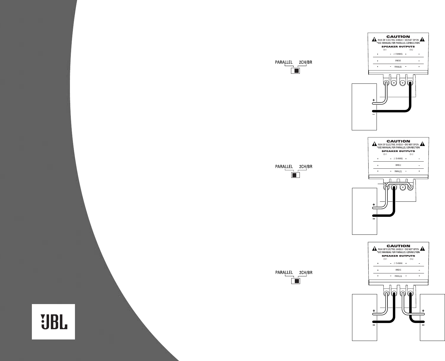
Included below are three application
diagrams that will help you plan
your A6000GTi installation. Figures 7
through 9 show how to configure the
JBL A6000GTi subwoofer amplifier for
bridged-mono, parallel-mono and
2-channel operation (see Setting Up the
GTi Amplifier).
IMPORTANT: If the nominal impedance
of the speaker system is close to 2
ohms, you may try both bridged and
parallel configurations to determine
which one performs better. Remember
to set the output mode switch to the
appropriate setting when changing
configurations.
NOTE: For simplicity, Figures 7 through
9 do not show power, remote and input
connections (see page 5).
A6000GTi Amplifier
(partial output panel)
Subwoofer
System
2 to 4
ohms
Subwoofer
System
2 to 4
ohms
Set Output Mode
to 2CH/BR
(on input panel)
See “Setting The Crossover”
on Page 8
to Adjust Crossover Controls
A6000GTi Amplifier
(partial output panel)
Set Output Mode
to PARALLEL
(on input panel)
See “Setting The Crossover”
on Page 8
to Adjust Crossover Controls Subwoofer
System
2 ohms
or less
jumper
A6000GTi Amplifier
(partial output panel)
Set Output Mode
to 2CH/BR
(on input panel)
See “Setting The Crossover”
on Page 8
to Adjust Crossover Controls Subwoofer
System
2 ohms
or more
Figure 7. The JBL A6000GTi
subwoofer amplifier is set
to bridged mode to drive a
subwoofer system. Only use
this mode when the nominal
equivalent or total impedance
of the speaker system is
2 ohms or greater.
Figure 9. The JBL A6000GTi
subwoofer amplifier is set
to 2-channel mode to drive
a pair of subwoofers or
subwoofer systems with
nominal equivalent or total
impedances of 2 to 4 ohms.
Figure 8. The JBL A6000GTi
subwoofer amplifier is set
to parallel mode to drive a
subwoofer system. Only
use this mode when the
nominal equivalent or total
impedance of the speaker
system is less than 2 ohms.
NOTE: A jumper is added
between the + terminals.
7
MAKING THE CONNECTIONS
A3000GTI SPEAKER
CONNECTIONS
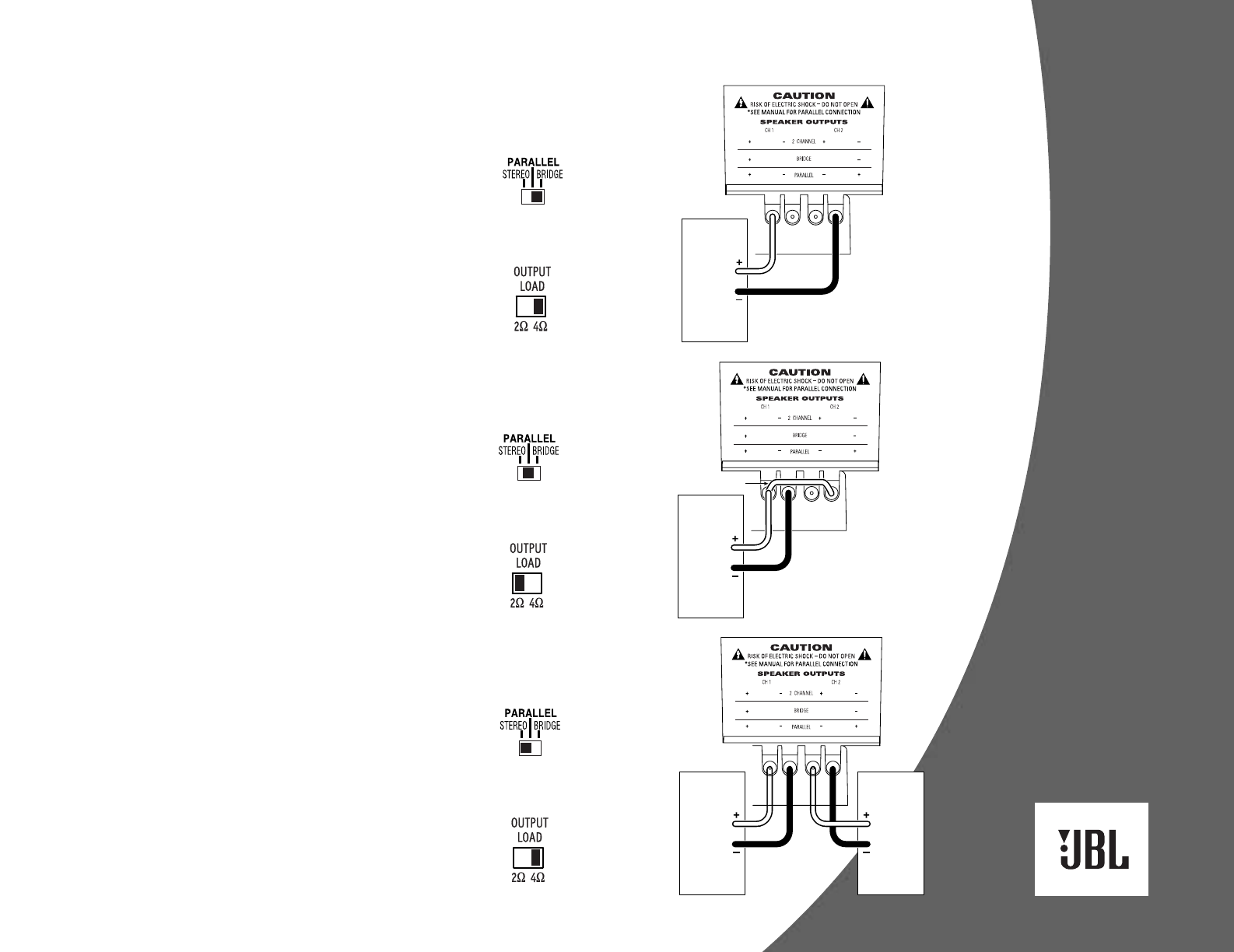
Included below are three application
diagrams that will help you plan your
A3000GTi installation. Figures 10
through 12 show how to configure
the JBL A3000GTi amplifier for
bridged-mono, parallel-mono and
2-channel operation (also see
Setting Up the GTi Amplifier).
NOTE: For simplicity, Figures 10 through
12 do not show power, remote and input
connections (see page 5).
A3000GTi Amplifier
(partial output panel)
2 to 4
ohms
2 to 4
ohms
L Speaker
System
R Speaker
System
Set Output Mode
to STEREO
(on input panel)
See “Setting The Crossover”
on Page 8
to Adjust Crossover Controls
A3000GTi Amplifier
(partial output panel)
Set Output Mode
to PARALLEL
(on input panel)
Subwoofer
System
2 ohms
or less
jumper
See “Setting The Crossover”
on Page 8
to Adjust Crossover Controls
A3000GTi Amplifier
(partial output panel)
Set Output Mode
to BRIDGE
(on input panel)
Subwoofer
System
2 ohms
or more
See “Setting The Crossover”
on Page 8
to Adjust Crossover Controls
Figure 10. The JBL A3000GTi
amplifier is set to bridged
mode to drive a subwoofer
system. Only use this mode
when the nominal equivalent
or total impedance of the
speaker system is 2 ohms
or greater.
Figure 12. The JBL A3000GTi
amplifier is set to stereo
mode to drive a pair of full-
range speaker systems with
nominal equivalent or total
impedances of 2 to 4 ohms.
Figure 11. The JBL A3000GTi
amplifier is set to parallel
mode to drive a subwoofer
system. Only use this mode
when the nominal equivalent
or total impedance of the
speaker system is less than
2 ohms.
NOTE: A jumper is added
between the + terminals.
OUTPUT LOAD SWITCH
The Output Load switch is used to
optimize amplifier performance when
driving a full-range signal. Set the
switch according to the nominal imped-
ance of the load: Use the 4-ohm mode
when driving loads with a nominal
impedance greater than 2 ohms and the
2-ohm mode when driving loads with a
nominal impedance of 2 ohms or less.

8
SETTING UP THE GTI AMPLIFIER
SETTING INPUT
SENSITIVITY
NOTE: You can use the supplied
REMOTE LEVEL control to fine-tune
the input sensitivity or to adjust the
level of the bass according to the
program material after the amplifier’s
LEVEL control has been set properly.
Connect the remote module’s attached
cable to the REMOTE LEVEL (RJ45) jack
on the amplifier’s input panel. Start with
the REMOTE LEVEL Control in its maxi-
mum (clockwise) position.
1. Initially, turn the amplifier’s LEVEL
control to the minimum (clockwise)
position.
2. Reconnect the (–) negative lead to
your vehicle’s battery. Apply power
to the audio system and play a
favorite music track.
3. Increase the source unit’s volume
control to the maximum listening
position. Slowly turn the amplifier’s
LEVEL control counterclockwise and
observe the I/OPT and E/OPT LEDs
(on the amplifier’s top).
• In the bridged or 2-channel mode,
at the ideal setting, the E/OPT LED
should flash on musical peaks to
indicate the amplifier is producing
maximum voltage. If the I/OPT LED
flashes in bridged mode, this
indicates the speaker system’s
impedance is lower than 2 ohms
and the amplifier should be
configured in the parallel mode.
• In the parallel mode, at the ideal
setting, the I/OPT LED should
flash on musical peaks to indicate
that the amplifier is producing max-
imum current.
If either the I/OPT or E/OPT LED is
on steadily, the amplifier is being
overdriven and your speakers may
be in jeopardy. Turn the LEVEL
control back slightly until the I/OPT or
E/OPT LED flashes on musical peaks.
SETTING PHASE
1. Initially set the PHASE control to 0°.
Play a favorite audio track that has
significant bass output.
2. Continue listening to the music and
have another person slowly adjust
the PHASE control towards 180° and
back to 0° again.
3. Repeat Step 2 as needed until you
find a setting that produces the most
mid-bass output.
NOTE: For applications using multiple
GTi amplifiers where the highest SPL
is desired at a single point in the
vehicle (i.e., SPL competition), adjust
the PHASE controls on all amplifiers
so all speakers are in phase at the
microphone position. This will pro-
vide the highest SPL when measured
with an SPL meter.
SETTING DBO
DBO (or Dynamic Bass Optimizer) is
a 12dB/octave high-pass filter with vari-
able frequency (20Hz to 80Hz)
and variable boost (0 to +12dB) at
the cutoff frequency.
NOTE: During DBO adjustment, you can
audition the effect by setting the DBO
switch to OFF and then back to ON.
NOTE: The A3000GTi can be used
to drive a pair of stereo mid-bass
speakers. In this case, use the DBO
to set the high-pass filter (from 20Hz to
80Hz) and use the crossover to set the
low-pass filter (from 80Hz to 320Hz).
For a vented box where a subwoofer
is prone to overexcursion below the
tuned frequency, set DBO to ON and set
the DBO HP FREQ control 10Hz below
the box’s resonant (tuned)
frequency (e.g., 30Hz for a vented
box tuned to 40Hz). Power typically
wasted in this region will now be
conserved and instead be available
for frequencies the enclosure can
reproduce. Use the DBO BOOST
control to boost the bass at the set
frequency by as much as 12dB, as
shown in Figure 13.
For a sealed enclosure, use DBO to
enhance the middle of the bass region.
Set DBO to ON, and then set the DBO
HP FREQ control to 35Hz to 40Hz. Adjust
the DBO BOOST control for a big and
full bass sound. Alternatively, for a
tighter-sounding bass, set the DBO HP
FREQ control between 45Hz to 50Hz and
also adjust the DBO BOOST control
according to your preference.
For an infinite baffle application,
set DBO to ON, and then set the
HP FREQ control to the speaker’s Fs
value (to keep the subwoofer from
trying to create bass below the
resonant frequency). Adjust the DBO
BOOST control according to your taste.
–9
–6
–3
0
–12 20 80 Freq. (Hz)
dB
DBO HP FREQ Control
(adjusts cut-off
frequency)
–6
0
6
12
–12 20 80 Freq. (Hz)
dB
DBO BOOST Control
(adjusts boost amount
at cut-off frequency)
HP FREQ
20Hz80Hz
BOOST
MAX MIN
Figure 13. Frequency response curves
show typical DBO control ranges for
the JBL A6000GTi or A3000GTi amplifier.
SETTING THE CROSSOVER
IMPORTANT: If you plan to use the
A3000GTi to drive full-range speakers,
set the crossover mode switch to FLAT
and skip to the next section, “Setting
Input Sensitivity.”
1. Depending on your system plan,
set the A3000GTi’s crossover mode
switch to LP (low-pass) or HP (high-
pass). The A6000GTi is a low-pass
amplifier only, designed to drive
subwoofers. No crossover switch
is provided.
2. The crossover slope has two
settings: 12 (dB per octave) or
24 (dB per octave). Select the
slope that best suits your taste, but
consider that a steeper low-pass
filter will make the subwoofers
sound less directional (since more
midrange will be filtered from the
signal). A steeper high-pass filter will
reduce a small speaker’s
unnecessary cone excursion at
the lowest frequencies, which
will increase power handling
and reduce distortion.
3. Set the A3000GTi’s HP FREQ control
to allow the speakers to make
as much bass as possible while
minimizing distortion caused by
small speakers trying to reproduce
the lowest frequencies. The best
setting is one where the speakers
produce crisp, clear impact without
being overdriven.
4. For either amplifier, set the LP FREQ
control so vocal information is not
reproduced by the subwoofers, and
the subwoofers’ sound blends with
the sound of the midrange speakers
without any missing information.
NOTE: The LP FREQ control can be
set to any frequency between 32Hz
and 320Hz.
9
SETTING UP THE GTI AMPLIFIER
REPLACING THE FUSE
OR NEON TUBES
The JBL A6000/A3000GTi amplifier
is equipped with an internal fuse, a
20-inch neon tube and two 6-inch neon
tubes. Should the fuse or a neon tube
fail, perform the following steps
to replace the part:
NOTE: For neon tube replacement, see
your authorized JBL car audio dealer to
purchase new StreetGlow®neon tubes
in 6- or 20-inch sizes.
NOTE: Although the following
steps discuss and illustrate how
to disassemble a JBL A6000GTi,
the disassembly procedure for a
JBL A3000GTi is similar.
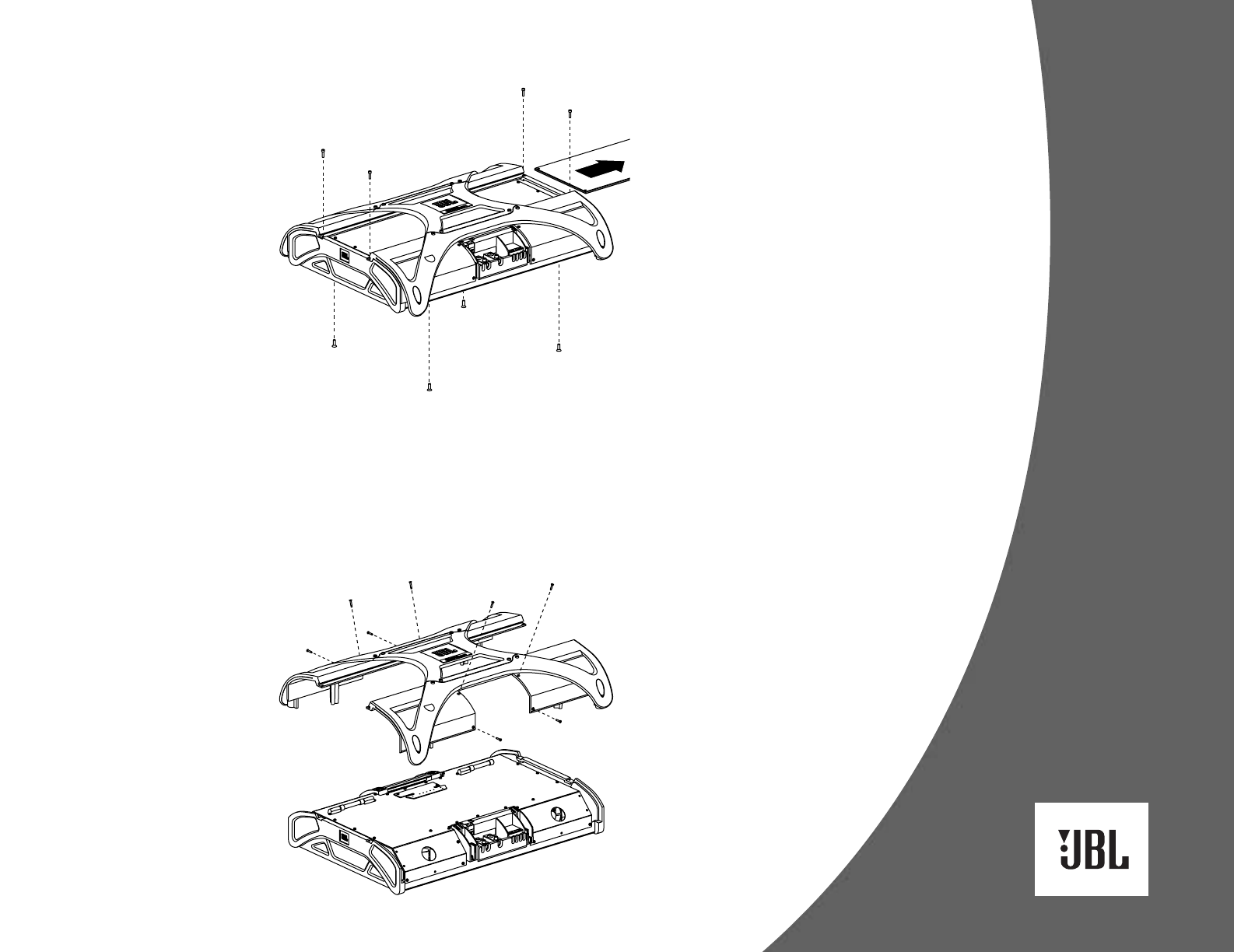
1. Disconnect and unmount the
amplifier from the vehicle. On a
soft surface, turn the amplifier over
to view the bottom. Using a T-25
screwdriver, remove the four large
Torx-head screws along the bottom
edges and set them aside (see
Figure 14).
2. Turn the amplifier over to view the
top. Using a 5 ⁄32-inch Allen wrench,
remove the four cap screws on the
clear cover and set them aside (see
Figure 14).
3. Slide the clear cover off and set it
aside (see Figure 14).
Figure 14. Removing bottom screws and
the clear cover from the A6000GTi
amplifier. NOTE: Do not remove the logo
badge assembly.
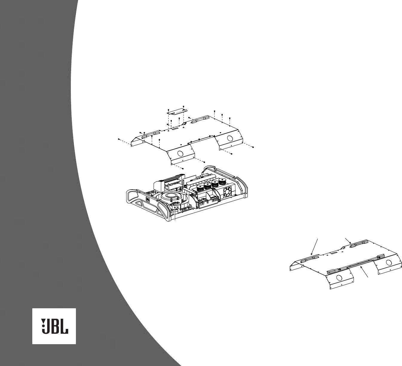
4. Using a T-15 screwdriver, remove the
four Torx-head screws around the
output panel and set them aside (see
Figure 15).
5. Repeat Step 4 for the input panel
(see Figure 15).
6. Remove the cover and set it aside
(see Figure 15).
Figure 15. Removing the input and
output screws and the cover from the
A6000GTi amplifier.
10
SETTING UP THE GTI AMPLIFIER
7. Using a T-15 screwdriver, remove the
two Torx-head screws on the display
board and set them aside
(see Figure 16 below). Disconnect
the ribbon cable from display board.
8. Using a T-15 screwdriver, remove the
16 Torx-head screws on the
perforated shield and set them aside
(see Figure 16).
Figure 16. Removing the fuse from the
A6000GTi amplifier.
9. Using a small flat-blade screwdriver,
disconnect the wiring for the neon
tubes.
10. Remove the perforated shield and
set it aside.
11. Replace the fuse or a neon tube as
follows:
• To replace the fuse on the ampli-
fier circuit board (see Figure 16),
use a 7⁄16-inch hex-socket driver
to remove the two fuse nuts and
then discard the failed fuse. Fasten
the replacement fuse
in place using the two fuse nuts.
• To replace a neon tube (see Figure
17), use a T-15 screwdriver and pli-
ers to remove the two
Torx-head screws, nuts and
washers on the two clamps that
hold each neon tube in place.
Remove the failed neon tube
and unscrew its wires.
On the replacement neon tube, clip off
the cigarette lighter adapter. Then strip
the wires and screw the ends to the
connector. Refasten the two clamps
with hardware in place around the
neon tube. If needed, repeat this proce-
dure for another failed neon tube.
Figure 17. Neon tube locations on the
A6000GTi amplifier.
12. Reassemble the amplifier in reverse
order, as discussed in Steps 1
through 10.
Failed
Fuse
20" Neon Tube
(under shield)
6" Neon Tubes

11
TROUBLESHOOTING
SYMPTOM LIKELY CAUSE SOLUTION
No audio No voltage at power Check BATT+, REMOTE and
(Power LED is off) or remote terminal GND – terminals with VOM for
blown fuse or poor connection
Internal fuse blown Replace internal fuse
(incorrect power (see Replacing the Fuse
connections) or Neon Tubes section)
No audio Low or high voltage Check BATT+ terminal with
(Power LED at power terminal VOM for voltage between
is flashing) 10 and 16 Vdc; if not within
limits, check vehicle’s
electrical system
No audio Direct current on Disconnect cable from
(Power and speaker output(s) REMOTE terminal; if Fault LED
Fault LEDs is still on, contact local JBL
are on) service center
No audio Internal amplifier Check for blocked vents
(Power and temperature is over or whether the ambient
Thermal LEDs 85° C temperature is above 85° C
are on)
Distorted audio Amplifier’s gain is Properly adjust the
(I OPT and/or set to High LEVEL control (see
E OPT LED[s] Setting Input
are on more Sensitivity section)
than off)
Distorted audio Defective source unit Try new source unit
(I OPT and/or
E OPT LED[s] Shorted speaker Disconnect wires from
work correctly) wires SPEAKER OUTPUTS and
check for shorts between
wires, or between a wire and
the vehicle’s chassis
Music lacks Speakers are out Check speaker connections
“punch” of phase (see sections on speaker
connections)
Wrong output mode Verify output mode setting
(see Making the Connections
section)
Neon tubes do No voltage to neon tubes Check LIGHTING
not light for +12 Vdc terminal with VOM
Neon tubes are dead Replace neon tubes
(see Replacing the Fuse
or Neon Tubes section)
3000 Watts Parallel Bridge
Thermal CH 1
CH 2 Signal -18 dB -9 dB E Opt I Opt
Power
Fault
A3000GTi
6000 Watts Parallel Bridge
Power
Thermal Signal -18 dB -9 dB E Opt I Opt Fault
A6000GTi
Figure 18. Display indicates Power Output and Protection status.

Declaration of Conformity
We, Harman Consumer Group International
2, route de Tours
72500 Chateau-du-Loir
France
declare in own responsibility that the products
described in this owner’s manual are in compliance
with technical standards:
EN 55013:2001
EN 55020:2002
Emmanuel Millot
Harman Consumer Group International
Chateau-du-Loir, France 05/04
JBL Consumer Products
250 Crossways Park Drive, Woodbury, NY 11797 USA
© 2004 Harman International Industries, Incorporated
JBL and Crown are registered trademarks of
Harman International Industries, Incorporated.
Part No. GTIAMPOM4/04 www.jbl.com
Features, specifications and appearance are subject to change without notice.
