Jeep 2014 Grand Cherokee Owners Manual Diesel Supplement
2015-10-23
: Jeep Jeep-2014-Jeep-Grand-Cherokee-Owners-Manual-817357 jeep-2014-jeep-grand-cherokee-owners-manual-817357 jeep pdf
Open the PDF directly: View PDF ![]() .
.
Page Count: 118 [warning: Documents this large are best viewed by clicking the View PDF Link!]
- INTRODUCTION
- THINGS TO KNOW BEFORE STARTING YOUR VEHICLE
- UNDERSTANDING YOUR INSTRUMENT PANEL
- STARTING AND OPERATING
- STARTING PROCEDURES
- NORMAL OPERATION
- ENGINE BLOCK HEATER — IF EQUIPPED
- FUEL REQUIREMENTS
- Fuel Specifications
- Biodiesel Fuel Requirements
- Biodiesel Fuel Properties — Low Ambient Temperatures
- Fuel Quality — Must Comply With ASTM Standards
- Fuel Oxidation Stability — Must Use Fuel Within Six Months Of Manufacture
- Fuel Water Separation — Must Use Mopar Approved Fuel Filter Elements
- Fuel In Oil Dilution — Must Adhere To Required Oil Change Interval
- Biodiesel Fuel Filter Change Intervals
- TRAILER TOWING
- DIESEL EXHAUST FLUID
- ADDING FUEL
- MAINTAINING YOUR VEHICLE
- ENGINE COMPARTMENT — 3.0L DIESEL
- MAINTENANCE PROCEDURES
- FLUID CAPACITIES
- FLUIDS, LUBRICANTS AND GENUINE PARTS
- MAINTENANCE SCHEDULE
- INDEX

Grand Cherokee
Chrysler Group LLC
OWNER’S MANUAL
2014 Grand Cherokee Diesel
14WK741-226-AB Second Edition Printed in U.S.A.
2014
DIESEL SUPPLEMENT
VEHICLES SOLD IN CANADA
With respect to any Vehicles Sold in Canada, the name
Chrysler Group LLC shall be deemed to be deleted and
the name Chrysler Canada Inc. used in substitution
therefore.
DRIVING AND ALCOHOL
Drunken driving is one of the most frequent causes of
accidents.
Your driving ability can be seriously impaired with
blood alcohol levels far below the legal minimum. If you
are drinking, don’t drive. Ride with a designated non-
drinking driver, call a cab, a friend, or use public trans-
portation.
WARNING!
Driving after drinking can lead to an accident. Your
perceptions are less sharp, your reflexes are slower,
and your judgment is impaired when you have been
drinking. Never drink and then drive.
This manual illustrates and describes the operation of
features and equipment that are either standard or
optional on this vehicle. This manual may also include a
description of features and equipment that are no
longer available or were not ordered on this vehicle.
Please disregard any features and equipment de-
scribed in this manual that are not on this vehicle.
Chrysler Group LLC reserves the right to make changes
in design and specifications, and/or make additions to
or improvements to its products without imposing any
obligation upon itself to install them on products pre-
viously manufactured.
Copyright © 2013 Chrysler Group LLC

TABLE OF CONTENTS
SECTION PAGE
1INTRODUCTION .............................................................3
2THINGS TO KNOW BEFORE STARTING YOUR VEHICLE .............................5
3UNDERSTANDING YOUR INSTRUMENT PANEL ...................................9
4STARTING AND OPERATING ..................................................33
5MAINTAINING YOUR VEHICLE ................................................71
6MAINTENANCE SCHEDULE ...................................................99
7INDEX ....................................................................109
1
2
3
4
5
6
7


A MESSAGE FROM CHRYSLER GROUP LLC
Chrysler Group LLC welcomes you as a turbocharged
diesel-powered vehicle owner. Your diesel vehicle will
sound, feel, drive and operate differently from a gasoline-
powered vehicle. It is important that you read and
understand this manual.
Almost 100% of the heavy trucks in the United States and
Canada are diesel-powered because of the fuel economy,
rugged durability, and high torque which permits pulling
heavy loads.
You may find that some of the starting, operating, and
maintenance procedures are different. However, they are
simple to follow and careful adherence to them will ensure
that you take full advantage of the features of this engine.
NOTE: Some aftermarket products may cause severe
engine/transmission and/or exhaust system damage.
Your vehicle’s Powertrain Control Systems can detect
and store information about vehicle modifications that
increase horsepower and torque output such as whether
or not performance-enhancing powertrain components,
commonly referred to as downloaders, power boxes, or
performance chips have been used.
This information cannot be erased and will stay in the
system’s memory even if the modification is removed. This
information can be retrieved by Chrysler Group LLC, and
service and repair facilities, when servicing your vehicle.
This information may be used to determine if repair will be
covered by New Vehicle Limited Warranty.
There is a probability that the use of a “performance chip”
will prohibit the engine from starting. In this instance, the
vehicle will need to be serviced by a authorized dealer in
order to return the vehicle to it’s factory settings.
4 INTRODUCTION


REMOTE STARTING SYSTEM
This system uses the Remote Keyless Entry
(RKE) transmitter to start the engine conve-
niently from outside the vehicle while still
maintaining security. The system has a range of
approximately 300 ft (91 m).
NOTE:
•The vehicle must be equipped with an automatic
transmission to be equipped with Remote Start.
•The Remote Start system will wait for the “Wait To
Start” amber telltale to extinguish before cranking the
engine. This allows time for the engine pre-heat cycle
to pre-heat the cylinder air, and is normal in cold
weather. Refer to “Electronic Vehicle Information Dis-
play (EVIC)” in “Understanding Your Instrument
Panel” for further information on the “Wait To Start”
amber telltale and the pre-heat cycle.
How To Use Remote Start
All of the following conditions must be met before the
engine will remote start:
•Shift lever in PARK
•Doors closed
•Hood closed
•HAZARD switch off
•BRAKE switch inactive (brake pedal not pressed)
•Battery at an acceptable charge level
•RKE PANIC button not pressed
•Fuel meets minimum requirement
•Water In Fuel Indicator Light is not illuminated
•“Wait To Start” telltale is not illuminated
6 THINGS TO KNOW BEFORE STARTING YOUR VEHICLE

WARNING!
•Do not start or run an engine in a closed garage or
confined area. Exhaust gas contains Carbon Mon-
oxide (CO) which is odorless and colorless. Carbon
Monoxide is poisonous and can cause serious in-
jury or death when inhaled.
•Keep Remote Keyless Entry (RKE) transmitters
away from children. Operation of the Remote Start
System, windows, door locks or other controls
could cause serious injury or death.
ENGINE BREAK-IN RECOMMENDATIONS
The diesel engine does not require a break-in period due
to its construction. Normal operation is allowed, provid-
ing the following recommendations are followed:
•Warm up the engine before placing it under load.
•
Do not operate the engine at idle for prolonged periods.
•Use the appropriate transmission gear to prevent
engine lugging.
•
Observe vehicle oil pressure and temperature indicators.
•Check the coolant and oil levels frequently.
•Vary throttle position at highway speeds when carry-
ing or towing significant weight.
NOTE: Light duty operation such as light trailer towing
or no load operation will extend the time before the
engine is at full efficiency. Reduced fuel economy and
power may be seen at this time.
The engine oil installed in the engine at the factory is a
high-quality energy conserving type lubricant. Oil changes
should be consistent with anticipated climate conditions
under which vehicle operations will occur. The recom-
mended viscosity and quality grades are shown under
“Fluids, Lubricants and Genuine Parts”, under “Maintain-
ing Your Vehicle” in this manual. NON-DETERGENT OR
STRAIGHT MINERAL OILS MUST NEVER BE USED.
2
THINGS TO KNOW BEFORE STARTING YOUR VEHICLE 7

UNDERSTANDING YOUR INSTRUMENT PANEL
CONTENTS
䡵INSTRUMENT CLUSTER .................10
䡵INSTRUMENT CLUSTER DESCRIPTIONS .....11
䡵ELECTRONIC VEHICLE INFORMATION
CENTER (EVIC) ........................21
▫EVIC Displays ........................22
▫Vehicle Information (Customer Information
Features) ............................31
3
INSTRUMENT CLUSTER
10 UNDERSTANDING YOUR INSTRUMENT PANEL

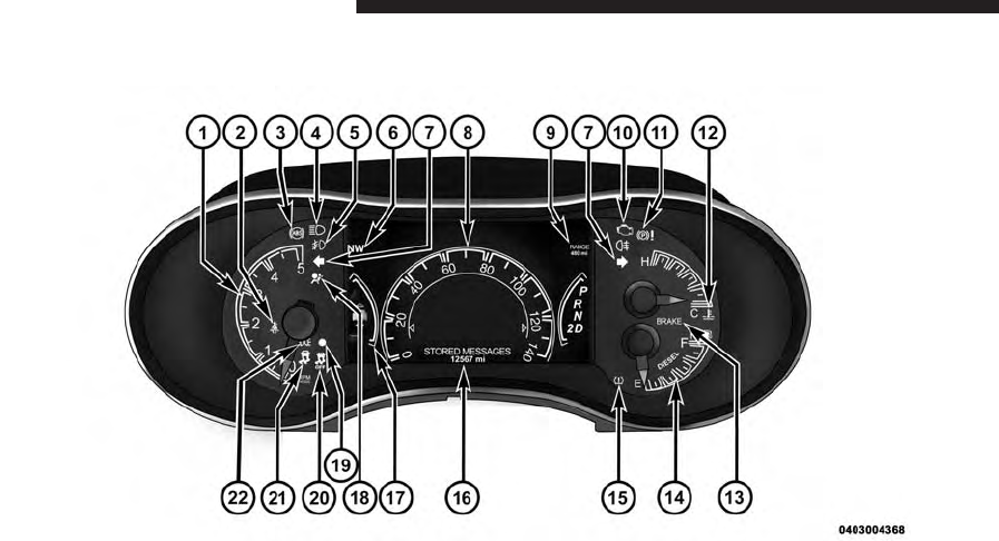
INSTRUMENT CLUSTER DESCRIPTIONS
1. Tachometer
Indicates the engine speed in revolutions per minute
(RPM x 1000).
2. Seat Belt Reminder Light
When the ignition switch is first turned to the
ON/RUN position, this light will turn on for four
to eight seconds as a bulb check. During the bulb
check, if the driver’s seat belt is unbuckled, a chime will
sound. After the bulb check or when driving, if the driver
or front passenger seat belt remains unbuckled, the Seat
Belt Indicator Light will flash or remain on continuously.
Refer to “Occupant Restraints” in “Things To Know
Before Starting Your Vehicle” in your Owner Manual on
the DVD for further information.
3. Anti-Lock Brake (ABS) Light
This light monitors the Anti-Lock Brake System
(ABS). The light will turn on when the ignition
switch is turned to the ON/RUN position and
may stay on for as long as four seconds.
If the ABS light remains on or turns on while driving, it
indicates that the Anti-Lock portion of the brake system
is not functioning and that service is required. However,
the conventional brake system will continue to operate
normally if the BRAKE warning light is not on.
If the ABS light is on, the brake system should be serviced
as soon as possible to restore the benefits of Anti-Lock
brakes. If the ABS light does not turn on when the
ignition switch is turned to the ON/RUN position, have
the light inspected by an authorized dealer.
3
UNDERSTANDING YOUR INSTRUMENT PANEL 11

4. High Beam Indicator
Indicates that headlights are on high beam.
5. Front Fog Light Indicator — If Equipped
This indicator will illuminate when the front fog
lights are on.
6. Selectable EVIC Information
This area of the cluster will display selectable information
(such as compass, outside temperature etc.). For further
information, refer to “Electronic Vehicle Information Cen-
ter (EVIC) — If Equipped” in your Owner Manual on the
DVD.
7. Turn Signal Indicator
The arrows will flash with the exterior turn sig-
nals when the turn signal lever is operated. A tone
will chime, and an EVIC message will appear if either
turn signal is left on for more than 1 mile (1.6 km).
NOTE: If either indicator flashes at a rapid rate, check
for a defective outside light bulb.
8. Speedometer
Indicates vehicle speed.
9. Selectable EVIC Information
This area of the cluster will display selectable informa-
tion (such as compass, outside temperature etc.). For
further information, refer to “Electronic Vehicle Informa-
tion Center (EVIC) — If Equipped” in your Owner
Manual on the DVD.
10. Malfunction Indicator Light (MIL)
The Malfunction Indicator Light (MIL) is part of
an Onboard Diagnostic System called OBD II that
monitors engine and automatic transmission con-
trol systems. The light will illuminate when the key is in
12 UNDERSTANDING YOUR INSTRUMENT PANEL
the ON/RUN position before engine start. If the bulb
does not come on when turning the key from OFF to
ON/RUN, have the condition checked promptly.
Certain conditions, poor fuel quality, etc., may illuminate
the light after engine start. The vehicle should be serviced
if the light stays on through several of your typical
driving cycles. In most situations, the vehicle will drive
normally and will not require towing.
CAUTION!
Prolonged driving with the Malfunction Indicator
Light (MIL) on could cause damage to the engine
control system. It also could affect fuel economy and
driveability. If the MIL is flashing, severe catalytic
converter damage and power loss will soon occur.
Immediate service is required.
WARNING!
A malfunctioning catalytic converter, as referenced
above, can reach higher temperatures than in normal
operating conditions. This can cause a fire if you
drive slowly or park over flammable substances such
as dry plants, wood, cardboard, etc. This could result
in death or serious injury to the driver, occupants or
others.
11. Parking Brake Indicator
This light indicates the parking brake is engaged.
3
UNDERSTANDING YOUR INSTRUMENT PANEL 13
12. Temperature Gauge
The temperature gauge shows engine coolant tempera-
ture. Any reading within the normal range indicates that
the engine cooling system is operating satisfactorily.
The gauge pointer will likely indicate a higher tempera-
ture when driving in hot weather, up mountain grades,
or when towing a trailer. It should not be allowed to
exceed the upper limits of the normal operating range.
CAUTION!
Driving with a hot engine cooling system could
damage your vehicle. If the temperature gauge reads
“H” pull over and stop the vehicle. Idle the vehicle
with the air conditioner turned off until the pointer
drops back into the normal range. If the pointer
(Continued)
CAUTION! (Continued)
remains on the “H” and you hear continuous chimes,
turn the engine off immediately and call an autho-
rized dealer for service.
WARNING!
A hot engine cooling system is dangerous. You or
others could be badly burned by steam or boiling
coolant. You may want to call an authorized dealer
for service if your vehicle overheats. If you decide to
look under the hood yourself, see “Maintaining Your
Vehicle”. Follow the warnings under the Cooling
System Pressure Cap paragraph.
14 UNDERSTANDING YOUR INSTRUMENT PANEL

13. Brake Warning Light
This light monitors various brake functions,
including brake fluid level and parking brake
application. If the brake light turns on it may
indicate that the parking brake is applied, that
the brake fluid level is low, or that there is a problem with
the anti-lock brake system reservoir.
If the light remains on when the parking brake has been
disengaged, and the fluid level is at the full mark on the
master cylinder reservoir, it indicates a possible brake
hydraulic system malfunction or that a problem with the
Brake Booster has been detected by the Anti-Lock Brake
System (ABS) / Electronic Stability Control (ESC) system.
In this case, the light will remain on until the condition
has been corrected. If the problem is related to the brake
booster, the ABS pump will run when applying the brake
and a brake pedal pulsation may be felt during each stop.
The dual brake system provides a reserve braking capac-
ity in the event of a failure to a portion of the hydraulic
system. A leak in either half of the dual brake system is
indicated by the Brake Warning Light, which will turn on
when the brake fluid level in the master cylinder has
dropped below a specified level.
The light will remain on until the cause is corrected.
NOTE: The light may flash momentarily during sharp
cornering maneuvers, which change fluid level condi-
tions. The vehicle should have service performed, and
the brake fluid level checked.
If brake failure is indicated, immediate repair is necessary.
3
UNDERSTANDING YOUR INSTRUMENT PANEL 15

WARNING!
Driving a vehicle with the red brake light on is
dangerous. Part of the brake system may have failed.
It will take longer to stop the vehicle. You could have
a collision. Have the vehicle checked immediately.
Vehicles equipped with the Anti-Lock Brake System
(ABS), are also equipped with Electronic Brake Force
Distribution (EBD). In the event of an EBD failure, the
Brake Warning Light will turn on along with the ABS
Light. Immediate repair to the ABS system is required .
Operation of the Brake Warning Light can be checked by
turning the ignition switch from the OFF position to the
ON/RUN position. The light should illuminate for ap-
proximately two seconds. The light should then turn off
unless the parking brake is applied or a brake fault is
detected. If the light does not illuminate, have the light
inspected by an authorized dealer.
The light also will turn on when the parking brake is
applied with the ignition switch in the ON/RUN position.
NOTE: This light shows only that the parking brake is
applied. It does not show the degree of brake application.
14. Fuel Gauge/Fuel Door Reminder
The fuel pump symbol points to the side of the vehicle
where the fuel door is located. The pointer shows the
level of fuel in the fuel tank when the ignition switch is in
the ON/RUN position.
15. Tire Pressure Monitoring Telltale Light
Each tire, including the spare (if provided),
should be checked monthly when cold (in the
morning before driven and before outside tem-
peratures rise) and inflated to the inflation
pressure recommended by the vehicle manufacturer on
the vehicle placard or tire inflation pressure label. (If your
vehicle has tires of a different size than the size indicated
16 UNDERSTANDING YOUR INSTRUMENT PANEL

on the vehicle placard or tire inflation pressure label, you
should determine the proper tire inflation pressure for
those tires.)
As an added safety feature, your vehicle has been
equipped with a Tire Pressure Monitoring System (TPMS)
that illuminates a low tire pressure telltale when one or
more of your tires is significantly under-inflated. Accord-
ingly, when the low tire pressure telltale illuminates, you
should stop and check your tires as soon as possible, and
inflate them to the proper pressure. Driving on a signifi-
cantly under-inflated tire causes the tire to overheat and
can lead to tire failure. Under-inflation also reduces fuel
efficiency and tire tread life, and may affect the vehicle’s
handling and stopping ability.
Please note that the TPMS is not a substitute for proper
tire maintenance, and it is the driver’s responsibility to
maintain correct tire pressure, even if under-inflation has
not reached the level to trigger illumination of the TPMS
low tire pressure telltale.
Your vehicle has also been equipped with a TPMS
malfunction indicator to indicate when the system is not
operating properly. The TPMS malfunction indicator is
combined with the low tire pressure telltale. When the
system detects a malfunction, the telltale will flash for
approximately one minute and then remain continuously
illuminated. This sequence will continue upon subse-
quent vehicle start-ups as long as the malfunction exists.
When the malfunction indicator is illuminated, the sys-
tem may not be able to detect or signal low tire pressure
as intended. TPMS malfunctions may occur for a variety
of reasons, including the installation of replacement or
alternate tires or wheels on the vehicle that prevent the
TPMS from functioning properly. Always check the
TPMS malfunction telltale after replacing one or more
tires or wheels on your vehicle, to ensure that the
replacement or alternate tires and wheels allow the TPMS
to continue to function properly.
3
UNDERSTANDING YOUR INSTRUMENT PANEL 17

CAUTION!
The TPMS has been optimized for the original
equipment tires and wheels. TPMS pressures and
warning have been established for the tire size
equipped on your vehicle. Undesirable system opera-
tion or sensor damage may result when using re-
placement equipment that is not of the same size,
type, and/or style. Aftermarket wheels can cause
sensor damage. Do not use tire sealant from a can or
balance beads if your vehicle is equipped with a
TPMS, as damage to the sensors may result.
16. Odometer Display/Electronic Vehicle Information
Center (EVIC) Display
Odometer Display
The odometer display shows the total distance the ve-
hicle has been driven.
U.S. Federal regulations require that upon transfer of
vehicle ownership, the seller certify to the purchaser the
correct mileage that the vehicle has been driven. If your
odometer needs to be repaired or serviced, the repair
technician should leave the odometer reading the same
as it was before the repair or service. If s/he cannot do so,
then the odometer must be set at zero, and a sticker must
be placed in the door jamb stating what the mileage was
before the repair or service. It is a good idea for you to
make a record of the odometer reading before the repair/
service, so that you can be sure that it is properly reset, or
that the door jamb sticker is accurate if the odometer
must be reset at zero.
Electronic Vehicle Information Center (EVIC) Display
The Electronic Vehicle Information Center (EVIC) fea-
tures a driver-interactive display that is located in the
instrument cluster. For further information, refer to
“Electronic Vehicle Information Center (EVIC)”.
18 UNDERSTANDING YOUR INSTRUMENT PANEL

The Shift Lever Indicator is self-contained within the
EVIC display. It displays the gear position of the auto-
matic transmission.
NOTE:
•You must apply the brakes before shifting from
PARK.
•The highest available transmission gear is displayed
in the lower right corner of the Electronic Vehicle
Information Center (EVIC) whenever the Electronic
Range Select (ERS) feature is active. Use the +/-
selector on the shift lever to activate ERS. Refer to
“Automatic Transmission” in “Starting And Operat-
ing” for further information.
When the appropriate conditions exist, this display
shows the Electronic Vehicle Information Center (EVIC)
messages. Refer to “Electronic Vehicle Information Cen-
ter” in your Owner Manual.
17. Selectable EVIC Menu
This area of the cluster will display the EVIC selectable
menu. For further information, refer to “Electronic Ve-
hicle Information Center (EVIC) — If Equipped” in your
Owner Manual.
18. Air Bag Warning Light
This light will turn on for four to eight seconds
as a bulb check when the ignition switch is first
turned to the ON/RUN position. If the light
is either not on during starting, stays on, or
turns on while driving, have an authorized dealer service
the air bag system immediately. Refer to “Occupant
Restraints” in “Things To Know Before Starting Your
Vehicle” in your Owner Manual on the DVD for further
information.
3
UNDERSTANDING YOUR INSTRUMENT PANEL 19

19. Vehicle Security Light
This light will flash rapidly for approximately
15 seconds when the vehicle theft alarm is
arming. The light will flash at a slower speed
continuously after the alarm is set. The security
light will also come on for about three seconds when the
ignition is first turned on.
20. Electronic Stability Control (ESC) OFF Indicator
Light — If Equipped
This light indicates the Electronic Stability Con-
trol (ESC) is off.
21. Electronic Stability Control (ESC) Activation/
Malfunction Indicator Light — If Equipped
The “ESC Activation/Malfunction Indicator
Light” in the instrument cluster will come on
when the ignition switch is turned to the
ON/RUN position. It should go out with the engine
running. If the “ESC Activation/Malfunction Indicator
Light” comes on continuously with the engine running, a
malfunction has been detected in the ESC system. If this
light remains on after several ignition cycles, and the
vehicle has been driven several miles (kilometers) at
speeds greater than 30 mph (48 km/h), see your autho-
rized dealer as soon as possible to have the problem
diagnosed and corrected.
NOTE:
•The “ESC Off Indicator Light” and the “ESC
Activation/Malfunction Indicator Light” come on
momentarily each time the ignition switch is turned
to ON/RUN.
•Each time the ignition is turned to ON/RUN, the
ESC system will be ON, even if it was turned off
previously.
20 UNDERSTANDING YOUR INSTRUMENT PANEL
•The ESC system will make buzzing or clicking
sounds when it is active. This is normal; the sounds
will stop when ESC becomes inactive following the
maneuver that caused the ESC activation.
22. Park/Headlight ON Indicator — If Equipped
This indicator will illuminate when the park
lights or headlights are turned on.
ELECTRONIC VEHICLE INFORMATION CENTER
(EVIC)
The Electronic Vehicle Information Center (EVIC) fea-
tures a driver-interactive display that is located in the
instrument cluster.
This system conveniently allows the driver to select a
variety of useful information by pressing the switches
mounted on the steering wheel.
Refer to “Electronic Vehicle Information Center –
If Equipped” in the Owner’s Manual for further infor-
mation.
Electronic Vehicle Information Center (EVIC)
3
UNDERSTANDING YOUR INSTRUMENT PANEL 21

EVIC Displays
When the appropriate conditions exist, the EVIC displays
the following messages:
•System Setup Unavailable – Vehicle Not in Park
•System Setup Unavailable – Vehicle in Motion
•Exhaust Filter XX% Full Safely Drive at Highway
Speeds To Remedy
•Exhaust Filter Full – Power Reduced See Dealer
•Exhaust Service Required – See Dealer Now
•Exhaust System – Filter XX% Full Service Required See
Dealer
•Exhaust System – Regeneration In Process Exhaust
Filter XX% Full
•Exhaust System – Regeneration Completed
•Engine Will Not Restart in XXXX mi DEF Low Refill
Soon
•Engine Will Not Restart in XXXX mi Refill DEF
•Engine Will Not Restart Refill DEF
•Service DEF System See Dealer
•Incorrect DEF Detected See Dealer
•Engine Will Not Restart in XXX mi Service DEF See
Dealer
•Engine Will Not Restart Service DEF System See
Dealer
Oil Life Reset
Your vehicle is equipped with an engine oil change
indicator system. The “Oil Change Required” message
will flash in the EVIC display for approximately 10 sec-
onds after a single chime has sounded, to indicate the
22 UNDERSTANDING YOUR INSTRUMENT PANEL

next scheduled oil change interval. The engine oil change
indicator system is duty cycle based, which means the
engine oil change interval may fluctuate, dependent
upon your personal driving style.
NOTE: Use the steering wheel EVIC controls for the
following procedure(s)
Vehicles Equipped With Passive Entry
1. Without pressing the brake pedal, press the ENGINE
START/STOP button and cycle the ignition to the
ON/RUN position (do not start the engine.)
2. Press and release the DOWN arrow button to scroll
downward through the main menu to “Vehicle Info”.
3. Press and release the RIGHT arrow button to access
the ”Oil Life” screen.
4. Press and hold the RIGHT arrow button for one
second to access the ”Oil Life Reset” screen.
5. Press and release the DOWN arrow button to select
“Yes”, then press and release the Right arrow button to
select reset of the Oil Life.
6. Press and release the Up arrow button to exit the EVIC
screen.
Vehicles Not Equipped With Passive Entry
1. Without pressing the brake pedal, cycle the ignition to
the ON/RUN position (do not start the engine.)
2. Press and release the DOWN arrow button to scroll
downward through the main menu to “ Vehicle Info”.
3. Press and release the RIGHT arrow button to access
the ” Oil Life” screen.
4. Press and hold the RIGHT arrow button for one
second to access the ” Oil Life Reset” screen.
3
UNDERSTANDING YOUR INSTRUMENT PANEL 23

5. Press and release the DOWN arrow button to select
“Yes”, then press and release the Right arrow button to
select reset of the Oil Life.
6. Press and release the Up arrow button to exit the EVIC
screen.
NOTE: If the indicator message illuminates when you
start the vehicle, the oil change indicator system did not
reset. If necessary, repeat this procedure.
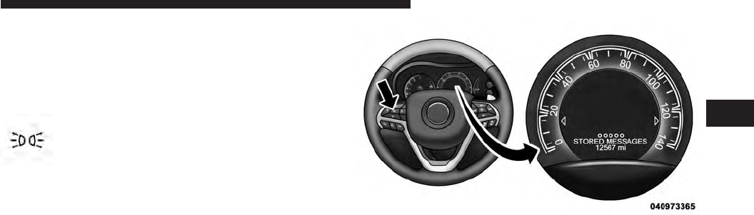
Fuel Filter Life Reset
The cluster will display the “Fuel System Service Re-
quired – See Dealer” or “Service Fuel Filter” message
when the fuel filter maintenance life is less than 5%. To
verify if this is a fuel filter change event, go to the “Fuel
Filter Life” screen in the “Vehicle Info” menu. When this
message appears, dealers should replace both frame
mounted and engine mounted fuel filters.
NOTE: Use the steering wheel EVIC controls for the
following procedure(s)
Vehicles Equipped With Passive Entry
1. Without pressing the brake pedal, press the ENGINE
START/STOP button and cycle the ignition to the
ON/RUN position (do not start the engine.)
2. Press and release the DOWN arrow button to scroll
downward through the main menu to “Vehicle Info”.
3. Press and release the RIGHT arrow button to access
the ”Fuel Filter Life” screen.
4. Press and hold the RIGHT arrow button for one
second to access the ”Fuel Filter Life Reset” screen.
5. Press and release the DOWN arrow button to select
“Yes”, then press and release the Right arrow button to
select reset of the Fuel Filter Life.
6. Press and release the Up arrow button to exit the EVIC
screen.
24 UNDERSTANDING YOUR INSTRUMENT PANEL

Vehicles Not Equipped With Passive Entry
1. Without pressing the brake pedal, cycle the ignition to
the ON/RUN position (do not start the engine.)
2. Press and release the DOWN arrow button to scroll
downward through the main menu to “Vehicle Info”.
3. Press and release the RIGHT arrow button to access
the ”Fuel Filter Life” screen.
4. Press and hold the RIGHT arrow button for one
second to access the ”Fuel Filter Life Reset” screen.
5. Press and release the DOWN arrow button to select
“Yes”, then press and release the Right arrow button to
select reset of the Fuel Filter Life.
6. Press and release the Up arrow button to exit the EVIC
screen.
NOTE: If the indicator message illuminates when you
start the vehicle, the oil change indicator system did not
reset. If necessary, repeat this procedure.
EVIC Amber Telltales
This area will show reconfigurable amber caution tell-
tales. These telltales include:
Water In Fuel Indicator Light
The “Water In Fuel Indicator Light” will illu-
minate when there is water detected in the fuel
filters. If this light remains on, DO NOT start
the vehicle before you drain the water from
the fuel filters to prevent engine damage. Refer to “Main-
tenance Procedures/Draining Fuel/Water Separator
Filters” in “Maintaining Your Vehicle” for further infor-
mation.
3
UNDERSTANDING YOUR INSTRUMENT PANEL 25
Wait To Start Light
The “Wait To Start” telltale will illuminate for
approximately two seconds when the ignition is
turned to the RUN position. It’s duration may be longer
based on colder operating conditions. Vehicle will not
initiate start until telltale is out. Refer to “Starting Proce-
dures” in “Starting and Operating” for further information.
NOTE: The “Wait To Start” telltale may not illuminate if
the intake manifold temperature is warm enough.
Low Diesel Exhaust Fluid Light
This telltale will turn on to indicate the Diesel
Exhaust Fluid (DEF) is low.
Diesel Particulate Filter (DPF) Messages
This engine meets all required diesel engine emissions
standards. To achieve these emissions standards, your
vehicle is equipped with a state-of-the-art engine and
exhaust system. These systems are seamlessly integrated
into your vehicle and managed by the Powertrain Con-
trol Module (PCM). The PCM manages engine combus-
tion to allow the exhaust system’s catalyst to trap and
burn Particulate Matter (PM) pollutants, with no input or
interaction on your part.
WARNING!
A hot exhaust system can start a fire if you park over
materials that can burn. Such materials might be
grass or leaves coming into contact with your exhaust
system. Do not park or operate your vehicle in areas
where your exhaust system can contact anything that
can burn.
26 UNDERSTANDING YOUR INSTRUMENT PANEL

Your vehicle has the ability to alert you to additional
maintenance required on your vehicle or engine. Refer to
the following messages that may be displayed on your
Electronic Vehicle Information Center (EVIC):
•Exhaust Filter XX% Full Safely Drive at Highway
Speeds to Remedy — This message will be displayed
in the Electronic Vehicle Information Center (EVIC) if
the exhaust particulate filter reaches 80% of its maxi-
mum storage capacity. Under conditions of exclusive
short duration and low speed driving cycles, your
diesel engine and exhaust after-treatment system may
never reach the conditions required to cleanse the filter
to remove the trapped PM. If this occurs, the “Exhaust
Filter XX% Full Safely Drive at Highway Speeds to
Remedy” message will be displayed in the EVIC. If
this message is displayed, you will hear one chime
to assist in alerting you of this condition. By simply
driving your vehicle at highway speeds for up to
20 minutes, you can remedy the condition in the
particulate filter system and allow your diesel engine
and exhaust after-treatment system to cleanse the filter
to remove the trapped PM and restore the system to
normal operating condition.
•Exhaust System — Regeneration In Process Exhaust
Filter XX% Full — This message indicates that the
Diesel Particulate Filter (DPF) is self-cleaning. Main-
tain your current driving condition until regeneration
is completed.
•Exhaust System — Regeneration Completed — This
message indicates that the Diesel Particulate Filter
(DPF) self-cleaning is completed. If this message is
displayed, you will hear one chime to assist in alerting
you of this condition.
•Exhaust Service Required — See Dealer Now — This
messages indicates regeneration has been disabled due
to a system malfunction. At this point the engine
Powertrain Control Module (PCM) will register a fault
code, the instrument panel will display a MIL light.
3
UNDERSTANDING YOUR INSTRUMENT PANEL 27

CAUTION!
See your authorized dealer, as damage to the exhaust
system could occur soon with continued operation.
•Exhaust Filter Full — Power Reduced See Dealer —
This message indicates the PCM has derated the
engine to limit the likelihood of permanent damage to
the after-treatment system. If this condition is not
corrected and a dealer service is not performed, exten-
sive exhaust after-treatment damage can occur. To
correct this condition it will be necessary to have your
vehicle serviced by your local authorized dealer.
CAUTION!
See your authorized dealer, as damage to the exhaust
system could occur soon with continued operation.
Diesel Exhaust Fluid (DEF) Warning Messages
Your vehicle will begin displaying warning messages
when the DEF level reaches a driving range of approxi-
mately 500 miles. If the following warning message
sequence is ignored, your vehicle may not restart unless
DEF is added with in the displayed mileage shown in the
EVIC message.
•Engine Will Not Restart in XXXX mi DEF Low Refill
Soon —
This message will display when DEF driving
range is less than 500 miles, DEF fluid top off is required
with in the displayed mileage. The message will be
displayed in the EVIC during vehicle start up with the
current allowed mileage and accompanied by a single
chime. The remaining mileage can be pulled up anytime
by way of the “Messages” list within the EVIC
•Engine Will Not Restart in XXXX mi Refill DEF —
This message will display when DEF driving range is
less than 200 miles. It is also displayed at 150 miles and
28 UNDERSTANDING YOUR INSTRUMENT PANEL

100 miles. DEF fluid top off is required with in the
displayed mileage. The message will be displayed in
the EVIC during vehicle start up with an updated
distance mileage, and it will be accompanied by a
single chime. Stating at 100 miles, remaining range will
be continuously displayed while operating the vehicle.
Chimes will also accompany the 75, 50 and 25 mile
remaining distances. The DEF Low telltale will be on
continuously until DEF fluid is topped off.
•Engine Will Not Restart Refill DEF — This message
will display when the DEF driving range is less than
1 mile, DEF fluid top off is required or the engine will
not restart. The message will be displayed in the EVIC
during vehicle start up, and it will be accompanied by
a single chime. The DEF Low telltale will be illumi-
nated continuously until DEF fluid tank is filled with a
minimum of two gallons of DEF.
Diesel Exhaust Fluid (DEF) Fault Warning
Messages
There are different messages which are displayed if the
vehicle detects that the DEF system has been filled with
a fluid other than DEF, has experienced component
failures, or when tampering has been detected.
When the DEF system needs to be serviced the following
warnings will display:
•Service DEF System See Dealer — This message will
display when the fault is initially detected and each
time the vehicle is started. The message will be accom-
panied by a single chime and the Malfunction Indica-
tor Light. We recommend you drive to your nearest
authorized dealer and have your vehicle serviced
immediately. If not corrected in 50 miles, vehicle will
enter the “Engine Will not restart in XXXmi Service
DEF See dealer” warning stage and message.
3
UNDERSTANDING YOUR INSTRUMENT PANEL 29

•Incorrect DEF Detected See Dealer — This message
will display if the DEF system has detected the incor-
rect fluid has been introduced to the DEF tank. The
message will be accompanied by a single chime. We
recommend you drive to your nearest authorized
dealer and have your vehicle serviced immediately. If
not corrected in 50 miles, vehicle will enter the Engine
Will not restart in XXX mi Service DEF See dealer
warning stage and message.
•Engine Will Not Restart in XXX mi Service DEF See
Dealer — This message is first displayed if the fault
detected is not serviced after 50 miles of operation. It is
also displayed at 150 miles 125 miles and 100 miles.
System service is required within the displayed mile-
age. The message will be displayed in the EVIC during
vehicle start up with an updated distance mileage, and
it will be accompanied by a single chime. Starting at
100 miles, remaining range will be continuously dis-
played while operating the vehicle. Chimes will also
accompany the 75, 50 and 25 mile remaining distances.
We recommend you drive to your nearest authorized
dealer and have your vehicle serviced immediately.
•Engine Will Not Restart Service DEF System See
Dealer — This message will display if DEF system
issue detected is not serviced during the allowed
period. Your engine will not restart unless your vehicle
is serviced by your authorized dealer. This message
will be displayed when under 1 mile until engine will
not start and each time the vehicle is started, and will
be continuously displayed. The message will be ac-
companied by a single chime. Your Malfunction Indi-
cator Light will be continuously illumined. We highly
recommend you drive to your nearest authorized
dealer if the message appears while engine is running.
30 UNDERSTANDING YOUR INSTRUMENT PANEL

•
Engine Will Not Start Service DEF System See Dealer
— This message will display when the fault detected is
not serviced after the Engine will not restart Service DEF
System See Dealer message is displayed on the next
subsequent restart. Your engine will not start unless you
vehicle is serviced by your authorized dealer. The mes-
sage will be accompanied by a single chime. Your
Malfunction Indicator Light will be continuously illumi-
nated. If the message appears and you can not start the
engine, we recommend you have your vehicle towed to
your nearest authorized dealer immediately.
NOTE:
•The gauge may take up to five seconds to update after
adding a gallon or more of Diesel Exhaust Fluid (DEF)
to the DEF tank. If you have a fault related to the DEF
system, the gauge may not update to the new level. See
your authorized dealer for service.
•The DEF gauge may also not immediately update after
a refill if the temperature of the DEF fluid is below
12°F (-11°C). The DEF line heater will possibly warm
up the DEF fluid and allow the gauge to update after
a period of run time. Under very cold conditions, it is
possible that the gauge may not reflect the new fill
level for several drives.
Vehicle Information (Customer Information
Features)
Press and release the UP or DOWN button until “Vehicle
Info” displays in the EVIC and press the OK button. Press
the UP and DOWN button to scroll through the available
information displays, then press OK to display anyone of
the following choices.
•Battery Voltage
Displays the actual battery voltage.
3
UNDERSTANDING YOUR INSTRUMENT PANEL 31

•Coolant Temp
Displays the actual coolant temperature.
•Trans Temperature
Displays the actual transmission sump temperature.
•Tire Pressure Monitor System
Displays the actual tire pressure
32 UNDERSTANDING YOUR INSTRUMENT PANEL

STARTING AND OPERATING
CONTENTS
䡵STARTING PROCEDURES .................35
▫Automatic Transmission .................36
▫Extreme Cold Weather ...................36
▫Normal Starting Procedure —
Keyless Enter-N-Go™ ...................37
▫Starting Fluids ........................38
䡵NORMAL OPERATION ...................39
▫Cold Weather Precautions ................39
▫Engine Idling .........................40
▫Stopping The Engine ....................41
▫Cooling System Tips —
Automatic Transmission..................42
䡵ENGINE BLOCK HEATER — IF EQUIPPED ....43
䡵FUEL REQUIREMENTS ...................44
▫Fuel Specifications .....................45
▫Biodiesel Fuel Requirements...............46
䡵TRAILER TOWING ......................49
▫Common Towing Definitions ..............49
4

▫Trailer Hitch Classification ...............52
▫Trailer Towing Weights (Maximum Trailer
Weight Ratings) .......................53
▫Trailer And Tongue Weight ...............54
▫Towing Requirements ...................55
▫Towing Tips ..........................60
䡵DIESEL EXHAUST FLUID .................62
▫System Overview ......................62
䡵ADDING FUEL .........................63
▫Avoid Using Contaminated Fuel ............66
▫Bulk Fuel Storage — Diesel Fuel ...........66
▫Diesel Exhaust Fluid Storage ..............67
▫Adding Diesel Exhaust Fluid ..............68
34 STARTING AND OPERATING
STARTING PROCEDURES
Before starting your vehicle, adjust your seat, both inside
and outside mirrors, and fasten your seat belts.
The starter is allowed to crank for up to 30-second
intervals. Waiting a few minutes between such intervals
will protect the starter from overheating.
WARNING!
•When leaving the vehicle, always make sure the
keyless ignition node is in the ⴖOFFⴖmode, remove
the Key Fob from the vehicle and lock the vehicle.
(Continued)
WARNING! (Continued)
•
Never leave children alone in a vehicle, or with
access to an unlocked vehicle. Leaving children in a
vehicle unattended is dangerous for a number of
reasons. A child or others could be seriously or
fatally injured. Children should be warned not to
touch the parking brake, brake pedal or the shift
lever.
•Do not leave the Key Fob in or near the vehicle (or
in a location accessible to children), and do not
leave the ignition of a vehicle equipped with
Keyless Enter-N-Go™ ACC or RUN mode. A child
could operate power windows, other controls, or
move the vehicle.
4
STARTING AND OPERATING 35

NOTE: Engine start up in very low ambient temperature
could result in evident white smoke. This condition will
disappear as the engine warms up.
CAUTION!
•
The engine is allowed to crank as long as 30 seconds.
If the engine fails to start during this period, please
wait at least two minutes for the starter to cool before
repeating start procedure.
•If the “Water in Fuel Indicator Light” remains on,
DO NOT START engine before you drain the water
from the fuel filters to avoid engine damage. Refer
to “Maintenance Procedures/Draining Fuel/Water
Separator Filter” in “Maintaining Your Vehicle” for
further information.
Automatic Transmission
Start the engine with the shift lever in the NEUTRAL or
PARK position. Apply the brake before shifting to any
driving range.
Extreme Cold Weather
The engine block heater is a resistance heater installed in
the water jacket of the engine. It requires a 110–115 Volt
AC electrical outlet with a grounded, three-wire exten-
sion cord. Its use is recommended for environments that
routinely fall below -10°F (-23°C). It should be used when
the vehicle has not been running overnight or longer
periods and should be plugged in two hours prior to
start. Its use is required for cold starts with temperatures
under -20°F (-28°C).
NOTE:
The engine block heater cord is a factory installed
option. If your vehicle is not equipped, heater cords are
available from your authorized MOPAR® dealer.
36 STARTING AND OPERATING

•A 12 Volt heater built into the fuel filter housing aids in
preventing fuel gelling. It is controlled by a built-in
thermostat.
•A Diesel Pre-Heat system both improves engine start-
ing and reduces the amount of white smoke generated
by a warming engine.
Normal Starting Procedure — Keyless
Enter-N-Go™
Observe the instrument panel cluster lights when starting
the engine.
NOTE: Normal starting of either a cold or a warm
engine is obtained without pumping or pressing the
accelerator pedal
1. Always apply the parking brake.
2. For vehicles equipped with an automatic transmis-
sion, place the shift lever into the PARK position.
3. Press and hold the brake pedal while pressing the
ENGINE START/STOP button once.
NOTE: A delay of the start of up to five seconds is
possible under very cold conditions. The ⬙Wait to Start⬙
telltale will be illuminated during the pre-heat process
and the start will commence upon the telltale going out.
CAUTION!
If the “Water in Fuel Indicator Light” remains on, DO
NOT START the engine before you drain the water
from the fuel filters to avoid engine damage. Refer to
“Maintenance Procedures/Draining Fuel/Water Sepa-
rator Filter” in “Maintaining Your Vehicle” for fur-
ther information.
4. The system will take over and attempt to start the
vehicle. If the vehicle fails to start, the starter will
disengage automatically after 30 seconds.
4
STARTING AND OPERATING 37
5. If you wish to stop the cranking of the engine prior to
the engine starting, press the button again.
6. Check that the oil pressure warning light has turned
off.
7. Release the parking brake.
Starting Fluids
The engine is equipped with a glow plug preheating
system. If the instructions in this manual are followed,
the engine should start in all conditions and no type of
starting fluid should be used.
WARNING!
•Do not leave children or animals inside parked
vehicles in hot weather. Interior heat build up may
cause serious injury or death.
(Continued)
WARNING! (Continued)
•When leaving the vehicle, always remove the key
fob and lock your vehicle.
•Never leave children alone in a vehicle, or with
access to an unlocked vehicle. Allowing children to
be in a vehicle unattended is dangerous for a
number of reasons. A child or others could be
seriously or fatally injured. Children should be
warned not to touch the parking brake, brake pedal
or the shift lever. Do not leave the key fob in or
near the vehicle (or in a location accessible to
children), and do not leave the ignition of a vehicle
equipped with Keyless Enter-N-Go™ in the ACC
or ON/RUN mode. A child could operate power
windows, other controls, or move the vehicle.
38 STARTING AND OPERATING
NORMAL OPERATION
Observe the following when the diesel engine is operat-
ing.
•All message center lights are off.
•Malfunction Indicator Light (MIL) is off.
•Engine Oil Pressure telltale is not illuminated.
•Voltmeter operation:
The voltmeter may show a gauge fluctuation at various
engine temperatures. This is caused by the glow plug
heating system. The number of cycles and the length of
the cycling operation is controlled by the engine control
module. Glow plug heater operation can run for several
minutes, once the heater operation is complete the volt-
meter needle will stabilize.
Cold Weather Precautions
Operation in ambient temperature below 32°F (0°C) may
require special considerations. The following charts sug-
gest these options:
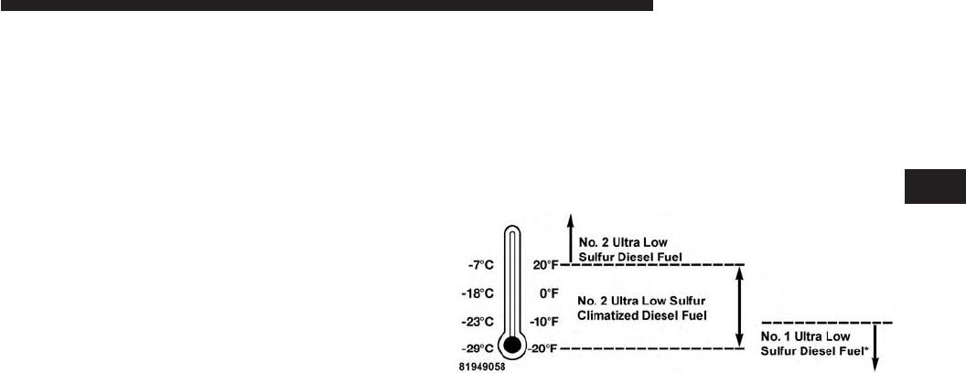
Fuel Operating Range
NOTE: Use “Ultra Low Sulfur Diesel Fuels” ONLY.
*No. 1 Ultra Low Sulfur Diesel Fuel should only be used
where extended arctic conditions (-10°F/-23°C) exist.
Fuel Operating Range Chart
4
STARTING AND OPERATING 39

NOTE:
•Use of Climatized Ultra Low Sulfur Diesel Fuel or
Number 1 Ultra Low Sulfur Diesel Fuel results in a
noticeable decrease in fuel economy.
•Climatized Ultra Low Sulfur Diesel Fuel is a blend of
Number 2 Ultra Low Sulfur and Number 1 Ultra Low
Sulfur Diesel Fuels which reduces the temperature at
which wax crystals form in fuel.
•The fuel grade should be clearly marked on the pump
at the fuel station.
•The engine requires the use of “Ultra Low Sulfur
Diesel Fuel”. Use of incorrect fuel could result in
engine and exhaust system damage. Refer to “Fuel
Requirements” in “Starting And Operating” for fur-
ther information.
Engine Oil Usage
Refer to “Maintenance Procedures” in “Maintaining Your
Vehicle” for the correct engine oil viscosity.
Engine Warm-Up
Avoid full throttle operation when the engine is cold.
When starting a cold engine, bring the engine up to
operating speed slowly to allow the oil pressure to
stabilize as the engine warms up.
If temperatures are below 32°F (0°C), operate the engine
at moderate speeds for five minutes before full loads are
applied.
Engine Idling
Avoid prolonged idling, long periods of idling may be
harmful to your engine because combustion chamber
temperatures can drop so low that the fuel may not burn
completely. Incomplete combustion allows carbon and
40 STARTING AND OPERATING

varnish to form on piston rings, cylinder head valves,
and injector nozzles. Also, the unburned fuel can enter
the crankcase, diluting the oil and causing rapid wear to
the engine.
Stopping The Engine
Idle the engine a few minutes before routine shutdown.
After full load operation, idle the engine three to five
minutes before shutting it down. This idle period will
allow the lubricating oil and coolant to carry excess heat
away from the combustion chamber, bearings, internal
components, and turbocharger. This is especially impor-
tant for turbocharged diesel engines.
NOTE: Refer to the following chart for proper engine
shutdown.
Driving
Condition Load
Turbo-
charger
Tempera-
ture
Idle Time
(min.)
Before
Engine
Shutdown
Stop and
Go
Empty Cool Less than
One
Stop and
Go
Medium One
Highway
Speeds
Medium Warm Two
City Traffic Maximum
GCWR
Three
Highway
Speeds
Maximum
GCWR
Four
Uphill
Grade
Maximum
GCWR
Hot Five
4
STARTING AND OPERATING 41
NOTE: Under certain conditions the engine fan will run
after the engine is turned off. These conditions are under
high load and high temperature conditions.
Cooling System Tips — Automatic Transmission
To reduce the potential for engine and transmission
overheating in high ambient temperature conditions,
take the following actions:
•City Driving — When stopped, shift the transmission
into NEUTRAL and increase engine idle speed.
•Highway Driving — Reduce your speed.
•Up Steep Hills — Select a lower transmission gear.
•Air Conditioning — Turn it off temporarily.
Do Not Operate The Engine With Low Oil
Pressure
If the low oil pressure warning light turns on while
driving, stop the vehicle and shut down the engine as
soon as possible. A chime will sound when the light
turns on.
NOTE: Do not operate the vehicle until the cause is
corrected. This light does not show how much oil is in the
engine. The engine oil level must be checked under the
hood.
CAUTION!
If oil pressure falls to less than normal readings, shut
the engine off immediately. Failure to do so could
result in immediate and severe engine damage.
42 STARTING AND OPERATING

Do Not Operate The Engine With Failed Parts
All engine failures give some warning before the parts
fail. Be on the alert for changes in performance, sounds,
and visual evidence that the engine requires service.
Some important clues are:
•engine misfiring or vibrating severely
•sudden loss of power
•unusual engine noises
•fuel, oil or coolant leaks
•sudden change, outside the normal operating range, in
the engine operating temperature
•excessive smoke
•oil pressure drop
ENGINE BLOCK HEATER — IF EQUIPPED
The engine block heater warms engine coolant and
permits quicker starts in cold weather. Connect the heater
cord to a ground-fault interrupter protected 110–115 Volt
AC electrical outlet with a grounded, three-wire exten-
sion cord.
Its use is recommended for environments that routinely
fall below -10°F (-23°C). It should be used when the
vehicle has not been running for long periods of time and
should be plugged in two hours prior to start. Its use is
required for cold starts with temperatures under -20°F
(-28°C).
To ensure reliable starting at these temperatures, use of
an externally powered electric engine block heater (avail-
able from your authorized dealer) is recommended.
4
STARTING AND OPERATING 43
WARNING!
Remember to disconnect the cord before driving.
Damage to the 110–115 Volt electrical cord could
cause electrocution.
NOTE: The block heater will require 110 Volts AC and
6.5 Amps to activate the heater element.
FUEL REQUIREMENTS
Use good quality diesel fuel from a reputable supplier in
your vehicle. Federal law requires that you must fuel this
vehicle with Ultra Low Sulfur Highway Diesel fuel
(15 ppm Sulfur maximum) and prohibits the use of Low
Sulfur Highway Diesel fuel (500 ppm Sulfur maximum) to
avoid damage to the emissions control system.
For most year-round service, No. 2 diesel fuel meeting
ASTM (formerly known as the American Society for
Testing and Materials) specification D-975 Grade S15 will
provide good performance. If the vehicle is exposed to
extreme cold (below 20°F or -7°C), or is required to operate
at colder-than-normal conditions for prolonged periods,
use climatized No. 2 diesel fuel or dilute the No. 2 diesel
fuel with 50% No. 1 diesel fuel. This will provide better
protection from fuel gelling or wax-plugging of the fuel
filters.
WARNING!
Do not use alcohol or gasoline as a fuel blending
agent. They can be unstable under certain conditions
and hazardous or explosive when mixed with diesel
fuel.
Diesel fuel is seldom completely free of water. To prevent
fuel system trouble, drain the accumulated water from
the fuel/water separator using the fuel/water separator
drain provided on the fuel filter housing. If you buy good
quality fuel and follow the cold weather advice above,
44 STARTING AND OPERATING

fuel conditioners should not be required in your vehicle.
If available in your area, a high cetane “premium” diesel
fuel may offer improved cold-starting and warm-up
performance.
CAUTION!
If the “Water in Fuel Indicator Light” remains on, DO
NOT START engine before you drain the water from
the fuel filter(s) to avoid engine damage. Refer to
“Maintenance Procedures/Draining Fuel/Water Sepa-
rator Filter” in “Maintaining Your Vehicle” for fur-
ther information.
Fuel Specifications
This diesel engine has been developed to take advantage
of the high energy content and generally lower cost No. 2
Ultra Low Sulfur diesel fuel or No. 2 Ultra Low Sulfur
climatized diesel fuels. Experience has shown that it also
operates on No. 1 Ultra Low Sulfur diesel fuels or other
fuels within specification.
NOTE:
•
If you accidentally fill the fuel tank with gasoline on
your diesel vehicle, do not start the vehicle. If you restart
your vehicle you risk damage the engine and fuel
system. Please call your authorized dealer for service.
•A maximum blend of 5% biodiesel meeting ASTM
specification D-975 may be used with your diesel
engine without any adjustments to regular service
schedules.
•Commercially available fuel additives are not neces-
sary for the proper operation of your diesel engine.
•No. 1 Ultra Low Sulfur diesel fuel should only be used
where extended arctic conditions (-10°F or -23°C) exist.
4
STARTING AND OPERATING 45

Biodiesel Fuel Requirements
A maximum blend of 5% biodiesel meeting ASTM speci-
fication D975 is recommended for use with your diesel
engine. If frequent operation with Biodiesel blends are
greater than 5% but not greater than 20% (B6–B20) is
desired, the maintenance schedule is subject to shorter
intervals.
The oil and filter change along with fuel filter replace-
ment is subject to shorter intervals when operating your
engine on biodiesel greater than 5%. Do not use biodiesel
greater than 20%.
For regular use of biodiesel blends greater than 5% but
not greater than 20% (B6–B20) it is important that you
understand and comply with these requirements. Refer
to the “Maintenance Chart” in the “Maintenance Sched-
ules” section for further direction.
CAUTION!
Failure to comply with Oil Change requirements for
vehicles operating on biodiesel blends greater than
5% but not greater than 20% (B6–B20) will result in
premature engine wear. Such wear is not covered by
the New Vehicle Limited Warranty.
Biodiesel is a fuel produced from renewable resources
typically derived from animal fat, rapeseed oil (Rapeseed
Methyl Ester (RME) base), or soybean oil (Soy Methyl
Ester (SME or SOME) base).
Biodiesel fuel has inherent limitations which require that
you understand and adhere to the following require-
ments if you use blends of Biodiesel greater than 5% but
not greater than 20% (B6–B20). There are no unique
restrictions for the use of B5.
46 STARTING AND OPERATING

CAUTION!
Use of blends greater than 20% is not approved. Use
of blends greater than 20% can result in engine
damage. Such damage is not covered by the New
Vehicle Limited Warranty.
Biodiesel Fuel Properties — Low Ambient
Temperatures
Biodiesel fuel may gel or solidify at low ambient tem-
peratures, which may pose problems for both storage and
operation. Precautions can be necessary at low ambient
temperatures, such as storing the fuel in a heated build-
ing or a heated storage tank, or using cold temperature
additives.
Fuel Quality — Must Comply With ASTM
Standards
The quality of Biodiesel fuel may vary widely. Only fuel
produced by a BQ9000 supplier to the following specifi-
cations may be blended to meet Biodiesel blend B6 – B20
fuel meeting ASTM specification D-7467:
•Petrodiesel fuel meeting ASTM specification D-975
and Biodiesel fuel (B100) meeting ASTM specification
D-6751
Fuel Oxidation Stability — Must Use Fuel Within
Six Months Of Manufacture
Biodiesel fuel has poor oxidation stability which can
result in long term storage problems. Fuel produced to
approved ASTM standards, if stored properly, provides
for protection against fuel oxidation for up to six months.
4
STARTING AND OPERATING 47

Fuel Water Separation — Must Use Mopar
Approved Fuel Filter Elements
Biodiesel fuel has a natural affinity to water and water
accelerates microbial growth. Your Mopar filtration sys-
tem is designed to provide adequate fuel water separa-
tion capabilities.
Fuel In Oil Dilution — Must Adhere To Required
Oil Change Interval
Fuel dilution of lubricating oil has been observed with
the use of Biodiesel fuel. Fuel in oil must not exceed 5%.
To ensure this limit is met your oil change interval must
be maintained with in the suggested schedule. The
regular use of biofuels greater than 5% and less than 20%
require intervals shorter than the outlined 10,000 miles
and must not exceed the suggested schedule. When
routinely operating on biofuels greater that 5% and less
than 20%, oil and filter replacement intervals must not
exceed 8,000 Miles or 6 months, which ever comes first.
Biodiesel Fuel Filter Change Intervals
The use of biofuels require intervals shorter than the
outlined 30,000 miles (48 280 km) and must not exceed
the suggested schedule. When operating on biofuels
greater that 5% and less than 20%, fuel filter replacement
intervals must not exceed 20,000 Miles (40 233 km).
NOTE:
Under no circumstances should oil change inter-
vals exceed 8,000 miles (12 875 km) or 6 months, if regular
operation occurs with greater than 5% and less than 20%
biodiesel blends. Under no circumstances should fuel filter
intervals exceed 20,000 miles (40 233 km), if regular
operation occurs with greater than 5% and less than 20%
biodiesel blends. Failure to comply with these Oil Change
and fuel filter requirements for vehicles operating on
biodiesel blends up to B20 may result in premature engine
wear. Such wear is not covered by the New Vehicle
Limited Warranty. The engine may suffer severe damage if
operated with concentrations of biodiesel higher than 20%.
48 STARTING AND OPERATING

TRAILER TOWING
In this section you will find safety tips and information
on limits to the type of towing you can reasonably do
with your vehicle. Before towing a trailer, carefully
review this information to tow your load as efficiently
and safely as possible.
To maintain the New Vehicle Limited Warranty coverage,
follow the requirements and recommendations in this
manual concerning vehicles used for trailer towing.
Common Towing Definitions
The following trailer towing related definitions will assist
you in understanding the following information:
Gross Vehicle Weight Rating (GVWR)
The GVWR is the total allowable weight of your vehicle.
This includes driver, passengers, cargo and tongue
weight. The total load must be limited so that you do not
exceed the GVWR. Refer to “Vehicle Loading/Vehicle
Certification Label” in “Starting and Operating” for
further information.
Gross Trailer Weight (GTW)
The GTW is the weight of the trailer plus the weight of all
cargo, consumables and equipment (permanent or tem-
porary) loaded in or on the trailer in its ⬙loaded and
ready for operation⬙condition.
The recommended way to measure GTW is to put your
fully loaded trailer on a vehicle scale. The entire weight
of the trailer must be supported by the scale.
WARNING!
If the gross trailer weight is 3,500 lbs (1 587 kg) or
more, it is mandatory to use a weight-distributing
hitch to ensure stable handling of your vehicle. If you
(Continued)
4
STARTING AND OPERATING 49

WARNING! (Continued)
use a standard weight-carrying hitch, you could lose
control of your vehicle and cause a collision.
Gross Combination Weight Rating (GCWR)
The GCWR is the total permissible weight of your vehicle
and trailer when weighed in combination.
Gross Axle Weight Rating (GAWR)
The GAWR is the maximum capacity of the front and rear
axles. Distribute the load over the front and rear axles
evenly. Make sure that you do not exceed either front
or rear GAWR. Refer to “Vehicle Loading/Vehicle Certi-
fication Label” in “Starting and Operating” for further
information.
WARNING!
It is important that you do not exceed the maximum
front or rear GAWR. A dangerous driving condition
can result if either rating is exceeded. You could lose
control of the vehicle and have a collision.
Tongue Weight (TW)
The tongue weight is the downward force exerted on the
hitch ball by the trailer. In most cases it should not be less
than 10% of the trailer load. You must consider this as
part of the load on your vehicle.
Frontal Area
The frontal area is the maximum height multiplied by the
maximum width of the front of a trailer.
50 STARTING AND OPERATING

Trailer Sway Control
The trailer sway control can be a mechanical telescoping
link that can be installed between the hitch receiver and
the trailer tongue that typically provides adjustable fric-
tion associated with the telescoping motion to dampen
any unwanted trailer swaying motions while traveling.
If equipped, the electronic Trailer Sway Control (TSC)
recognizes a swaying trailer and automatically applies
individual wheel brakes and/or reduces engine power to
attempt to eliminate the trailer sway.
Weight-Carrying Hitch
A weight-carrying hitch supports the trailer tongue
weight, just as if it were luggage located at a hitch ball or
some other connecting point of the vehicle. These kinds
of hitches are the most popular on the market today and
they are commonly used to tow small and medium sized
trailers.
Weight-Distributing Hitch
A weight-distributing system works by applying lever-
age through spring (load) bars. They are typically used
for heavier loads to distribute trailer tongue weight to the
tow vehicle’s front axle and the trailer axle(s). When used
in accordance with the manufacturer’s directions, it pro-
vides for a more level ride, offering more consistent
steering and brake control thereby enhancing towing
safety. The addition of a friction/hydraulic sway control
also dampens sway caused by traffic and crosswinds and
contributes positively to tow vehicle and trailer stability.
Trailer sway control and a weight distributing (load
equalizing) hitch are recommended for heavier Tongue
Weights (TW) and may be required depending on vehicle
and trailer configuration/loading to comply with Gross
Axle Weight Rating (GAWR) requirements.
4
STARTING AND OPERATING 51
WARNING!
•An improperly adjusted Weight Distributing Hitch
system may reduce handling, stability, braking
performance, and could result in a collision.
•
Weight Distributing Systems may not be compatible
with Surge Brake Couplers. Consult with your hitch
and trailer manufacturer or a reputable Recreational
Vehicle dealer for additional information.
Trailer Hitch Classification
The following chart provides the industry standard for
the maximum trailer weight a given trailer hitch class can
tow and should be used to assist you in selecting the
correct trailer hitch for your intended towing condition.
Trailer Hitch Classification Definitions
Class Max. Trailer Hitch
Industry Standards
Class I - Light Duty 2,000 lbs (907 kg)
Class II - Medium Duty 3,500 lbs (1 587 kg)
Class III - Heavy Duty 5,000 lbs (2 268 kg)
Class IV - Extra Heavy
Duty
10,000 lbs (4 540 kg)
Refer to the “Trailer Towing Weights (Maximum
Trailer Weight Ratings)” chart for the Maximum
Gross Trailer Weight (GTW) towable for your given
drivetrain.
All trailer hitches should be professionally installed
on your vehicle.
52 STARTING AND OPERATING
Trailer Towing Weights
(Maximum Trailer Weight Ratings)
The following chart provides the maximum trailer
weight ratings towable for your given drivetrain:
Engine Model Frontal Area Max. GTW
(Gross Trailer Wt.)
Max. Trailer Tongue
Wt. (See Note)
3.0L Diesel 4x2 55 sq ft (5.11 sq m) 7,400 lbs (3 357 kg) 740 lbs (336 kg)
3.0L Diesel 4x4 55 sq ft (5.11 sq m) 7,200 lbs (3 266 kg) 720 lbs (327 kg)
Refer to local laws for maximum trailer towing speeds.
NOTE: The trailer tongue weight must be considered as
part of the combined weight of occupants and cargo, and
should never exceed the weight referenced on the Tire
and Loading Information placard. Refer to “Tire Safety
Information” in “Starting and Operating” in your owners
manual for further information. The addition of passen-
gers and cargo may require reducing trailer tongue load
and Gross Trailer Weight (GTW). Redistributing cargo
(to the trailer) may be necessary to avoid exceeding Rear
Gross Axle Weight Rating (GAWR) of 3,700 lbs (1 678 kg).
4
STARTING AND OPERATING 53
Trailer And Tongue Weight
Always load a trailer with 60% of the weight in the front
of the trailer. This places 10% of the GTW on the tow
hitch of your vehicle. Loads balanced over the wheels or
heavier in the rear can cause the trailer to sway severely
side to side which will cause loss of control of the vehicle
and trailer. Failure to load trailers heavier in front is the
cause of many trailer collisions. Never exceed the maxi-
mum tongue weight stamped on your trailer hitch.
Consider the following items when computing the weight
on the rear axle of the vehicle:
•The tongue weight of the trailer
•The weight of any other type of cargo or equipment
put in or on your vehicle
•The weight of the driver and all passengers
54 STARTING AND OPERATING
NOTE: Remember that everything put into or on the
trailer adds to the load on your vehicle. Also, additional
factory-installed options or dealer-installed options must
be considered as part of the total load on your vehicle.
Refer to “Tire Safety Information/Tire and Loading In-
formation Placard” in “Starting and Operating” for fur-
ther information.
Towing Requirements
To promote proper break-in of your new vehicle drivetrain
components, the following guidelines are recommended.
CAUTION!
•Do not tow a trailer at all during the first 500 miles
(805 km) the new vehicle is driven. The engine, axle
or other parts could be damaged.
(Continued)
CAUTION! (Continued)
•Then, during the first 500 miles (805 km) that a
trailer is towed, do not drive over 50 mph (80 km/h)
and do not make starts at full throttle. This helps
the engine and other parts of the vehicle wear in at
the heavier loads.
Perform the maintenance listed in the “Maintenance
Schedule.” Refer to “Maintenance Schedule” for the
proper maintenance intervals. When towing a trailer,
never exceed the GAWR or GCWR ratings.
4
STARTING AND OPERATING 55
WARNING!
Improper towing can lead to a collision. Follow these
guidelines to make your trailer towing as safe as
possible:
•Make certain that the load is secured in the trailer
and will not shift during travel. When trailering
cargo that is not fully secured, dynamic load shifts
can occur that may be difficult for the driver to
control. You could lose control of your vehicle and
have a collision.
•When hauling cargo or towing a trailer, do not
overload your vehicle or trailer. Overloading can
cause a loss of control, poor performance or dam-
age to brakes, axle, engine, transmission, steering,
suspension, chassis structure or tires.
(Continued)
WARNING! (Continued)
•Safety chains must always be used between your
vehicle and trailer. Always connect the chains to
the hook retainers of the vehicle hitch. Cross the
chains under the trailer tongue and allow enough
slack for turning corners.
•Vehicles with trailers should not be parked on a
grade. When parking, apply the parking brake on
the tow vehicle. Put the tow vehicle transmission
in PARK. For four-wheel drive vehicles, make sure
the transfer case is not in NEUTRAL. Always,
block or ⴖchockⴖthe trailer wheels.
•GCWR must not be exceeded.
(Continued)
56 STARTING AND OPERATING

WARNING! (Continued)
•Total weight must be distributed between the tow
vehicle and the trailer such that the following four
ratings are not exceeded:
1. GVWR
2. GTW
3. GAWR
4. Tongue weight rating for the trailer hitch uti-
lized.
Towing Requirements — Tires
•Do not attempt to tow a trailer while using a compact
spare tire.
•Proper tire inflation pressures are essential to the safe
and satisfactory operation of your vehicle. Refer to
“Tires – General Information” in “Starting And Oper-
ating” for proper tire inflation procedures.
•Check the trailer tires for proper tire inflation pres-
sures before trailer usage.
•Check for signs of tire wear or visible tire damage
before towing a trailer. Refer to “Tires – General
Information” in “Starting And Operating” for the
proper inspection procedure.
•When replacing tires, refer to “Tires – General Infor-
mation” in “Starting And Operating” for the proper
tire replacement procedures. Replacing tires with a
higher load carrying capacity will not increase the
vehicle’s GVWR and GAWR limits.
4
STARTING AND OPERATING 57

Towing Requirements — Trailer Brakes
WARNING!
•
Do not connect trailer brakes to your vehicle’s hy-
draulic brake lines. It can overload your brake sys-
tem and cause it to fail. You might not have brakes
when you need them and could have an accident.
•
Towing any trailer will increase your stopping dis-
tance. When towing you should allow for additional
space between your vehicle and the vehicle in front
of you. Failure to do so could result in an accident.
CAUTION!
If the trailer weighs more than 1,000 lbs (454 kg)
loaded, it should have its own brakes and they
should be of adequate capacity. Failure to do this
could lead to accelerated brake lining wear, higher
brake pedal effort, and longer stopping distances.
•Do not interconnect the hydraulic brake system or
vacuum system of your vehicle with that of the trailer.
This could cause inadequate braking and possible
personal injury.
•An electronically actuated trailer brake controller is
required when towing a trailer with electronically
actuated brakes. When towing a trailer equipped with
a hydraulic surge actuated brake system, an electronic
brake controller is not required.
•Trailer brakes are recommended for trailers over
1,000 lbs (454 kg) and required for trailers in excess of
1,653 lbs (750 kg).
58 STARTING AND OPERATING
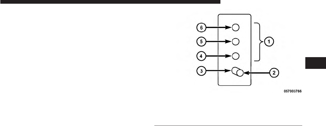
Towing Requirements — Trailer Lights And Wiring
Whenever you pull a trailer, regardless of the trailer size,
stoplights and turn signals on the trailer are required for
motoring safety.
The Trailer Tow Package may include a four- and seven-
pin wiring harness. Use a factory approved trailer har-
ness and connector.
NOTE: Do not cut or splice wiring into the vehicles
wiring harness.
The electrical connections are all complete to the vehicle
but you must mate the harness to a trailer connector.
Refer to the following illustrations.
Four-Pin Connector
1 — Female Pins 4 — Park
2 — Male Pin 5 — Left Stop/Turn
3 — Ground 6 — Right Stop/Turn
4
STARTING AND OPERATING 59
Towing Tips
Before setting out on a trip, practice turning, stopping
and backing the trailer up in an area away from heavy
traffic.
Automatic Transmission
The DRIVE range can be selected when towing. The
transmission controls include a strategy to avoid frequent
shifting when towing. However, if frequent shifting does
occur while in DRIVE, you can use the Paddle Shift
switches to manually select a lower gear.
NOTE: Using a lower gear while operating the vehicle
under heavy loading conditions, will improve perfor-
mance and extend transmission life by reducing exces-
sive shifting and heat buildup. This action will also
provide better engine braking.
Seven-Pin Connector
1 — Battery 5 — Ground
2 — Backup Lamps 6 — Left Stop/Turn
3 — Right Stop/Turn 7 — Running Lamps
4 — Electric Brakes
60 STARTING AND OPERATING

Paddle Shift Mode
•When using the Paddle Shift switches, select the
highest gear that allows for adequate performance and
avoids frequent downshifts. For example, choose “5” if
the desired speed can be maintained. Choose “4” or
“3” if needed to maintain the desired speed.
•To prevent excess heat generation, avoid continuous
driving at high RPM. Reduce vehicle speed as neces-
sary to avoid extended driving at high RPM. Return to
a higher gear or vehicle speed when grade and road
conditions allow.
Electronic Speed Control — If Equipped
•Do not use in hilly terrain or with heavy loads.
•When using the speed control, if you experience speed
drops greater than 10 mph (16 km/h), disengage until
you can get back to cruising speed.
•Use speed control in flat terrain and with light loads to
maximize fuel efficiency.
Cooling System
To reduce potential for engine and transmission over-
heating, take the following actions:
City Driving
When stopped for short periods of time, shift the trans-
mission into NEUTRAL and increase engine idle speed.
Highway Driving
Reduce speed.
Air Conditioning
Turn off temporarily.
4
STARTING AND OPERATING 61

DIESEL EXHAUST FLUID
Your vehicle is equipped with a Selective Catalytic Reduc-
tion system to meet the very stringent diesel emissions
standards required by the Environmental Protection
Agency. Selective Catalytic Reduction (SCR) is the first and
only technology in decades to be as good for the environ-
ment as it is good for business and vehicle performance.
The purpose of the SCR system is to reduce levels of NOx
(oxides of nitrogen emitted from engines) that are harm-
ful to our health and the environment to an almost
near-zero level. Small quantities of Diesel Exhaust Fluid
(DEF) are injected into the exhaust upstream of a catalyst
where, when vaporized, convert smog-forming nitrogen
oxides (NOx) into harmless nitrogen (N2) and water
vapor (H2O), two natural components of the air we
breathe. You can operate with the comfort that your
vehicle is contributing to a cleaner, healthier world
environment for this and generations to come.
System Overview
This vehicle is equipped with a Diesel Exhaust Fluid
(DEF) injection system and a Selective Catalytic Reduc-
tion (SCR) catalyst to meet the emission requirements.
The DEF injection system consists of the following com-
ponents:
•DEF tank
•DEF pump
•DEF injector
•Electronically-heated DEF lines
•NOx sensors
•Temperature sensors
•SCR catalyst
62 STARTING AND OPERATING
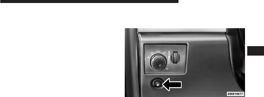
The DEF injection system and SCR catalyst enable the
achievement of diesel emissions requirements; while
maintaining outstanding fuel economy, drivability,
torque and power ratings.
Refer to “Electronic Vehicle Information Center (EVIC)”
in “Understanding Your Instrument Panel” for system
messages and warnings.
NOTE:
•Your vehicle is equipped with a DEF injection system.
You may occasionally hear an audible clicking noise
from under the vehicle at a stop. This is normal
operation.
•The DEF pump will run for a period of time after
engine shutdown to purge the DEF system. This is
normal operation and may be audible from the rear of
the vehicle.
ADDING FUEL
1. Press the fuel filler door release switch (located under
the headlamp switch).
2. Open the fuel filler door.
Fuel Filler Door Release Switch
4
STARTING AND OPERATING 63
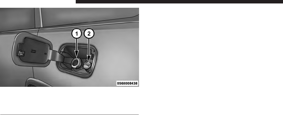
1 — Fuel Fill Location
2 — Diesel Exhaust Fluid Fill Location
NOTE: There is no fuel filler cap. A flapper door inside
the filler pipe seals the system.
3. Insert the fuel nozzle fully into the filler pipe – the
nozzle opens and holds the flapper door while refuel-
ing.
4. Fill the vehicle with fuel – when the fuel nozzle
“clicks” or shuts off the fuel tank is full.
5. Remove the fuel nozzle and close the fuel door.
Emergency Fuel Can Refueling
Most fuel cans will not open the flapper door.
A funnel is provided to open the flapper door to allow
emergency refueling with a fuel can.
Fuel and Diesel Exhaust Fluid Fill Location
64 STARTING AND OPERATING
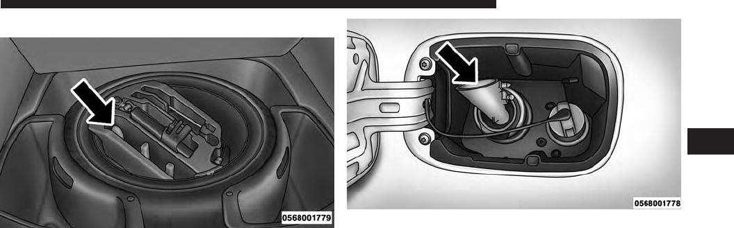
1. Retrieve funnel from the spare tire kit.
2. Insert funnel into same filler pipe opening as the fuel
nozzle.
NOTE: Ensure funnel is inserted fully to hold flapper
door open.
3. Pour fuel into funnel opening.
4. Remove funnel from filler pipe, clean off prior to
putting back in the spare tire kit.
Fuel Fill Funnel
Emergency Fuel Fill Location
4
STARTING AND OPERATING 65

CAUTION!
To avoid fuel spillage and overfilling, do not “top
off” the fuel tank after filling.
WARNING!
•Never have any smoking materials lit in or near the
vehicle when the fuel door is open or the tank is
being filled.
•Never add fuel when the engine is running. This is
in violation of most state and federal fire regula-
tions and may cause the “Malfunction Indicator
Light” to turn on.
•A fire may result if fuel is pumped into a portable
container that is inside of a vehicle. You could be
burned. Always place fuel containers on the
ground while filling.
Avoid Using Contaminated Fuel
Fuel that is contaminated by water or dirt can cause
severe damage to the engine fuel system. Proper main-
tenance of the engine fuel filter and fuel tank is essential.
Refer to “Maintenance Procedures” in “Maintaining Your
Vehicle” for further information.
Bulk Fuel Storage — Diesel Fuel
If you store quantities of fuel, good maintenance of the
stored fuel is also essential. Fuel contaminated with
water will promote the growth of “microbes.” These
microbes form “slime” that will clog the fuel filtration
system and lines. Drain condensation from the supply
tank and change the line filter on a regular basis.
NOTE: When a diesel engine is allowed to run out of
fuel, air is pulled into the fuel system.
66 STARTING AND OPERATING

If the vehicle will not start, refer to “Maintenance
Procedures/Priming If The Engine Has Run Out Of Fuel”
in “Maintaining Your Vehicle” for further information.
WARNING!
Do not open the high pressure fuel system with the
engine running. Engine operation causes high fuel
pressure. High pressure fuel spray can cause serious
injury or death.
Diesel Exhaust Fluid Storage
Diesel Exhaust Fluid (DEF) is considered a very stable
product with a long shelf life. If DEF is kept in tempera-
tures between 10° and 90°F (-12° and 32°C), it will last a
minimum of one year.
DEF is subject to freezing at the lowest temperatures.
For example, DEF may freeze at temperatures at or below
12° F (-11° C). The system has been designed to operate in
this environment.
NOTE: When working with DEF, it is important to know
that:
•Any containers or parts that come into contact with
DEF must be DEF compatible (plastic or stainless
steel). Copper, brass, aluminum, iron or non-stainless
steel should be avoided as they are subject to corrosion
by DEF.
•If DEF is spilled, it should be wiped up completely.
4
STARTING AND OPERATING 67
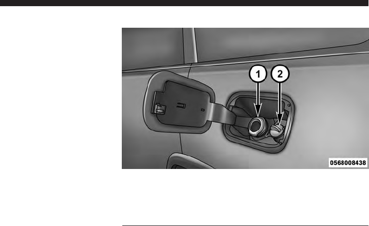
Adding Diesel Exhaust Fluid
The DEF gauge (located on the Electronic Vehicle Infor-
mation Center (EVIC) display) will display the level of
DEF remaining in the tank. Refer to “Electronic Vehicle
Information Center (EVIC)” in “Understanding Your
Instrument Panel” for further information.
NOTE: Driving conditions (altitude, vehicle speed, load,
etc.) will effect the amount of DEF that is used in your
vehicle.
DEF Fill Procedure
NOTE: Refer to “Fluids, Lubricants, and Genuine Parts”
in “Maintaining Your Vehicle” for the correct fluid type.
1.
Remove cap from DEF fill inlet (located in fuel door).
1 — Fuel Fill Location
2 — Diesel Exhaust Fluid Fill Location
Fuel and Diesel Exhaust Fluid Fill Location
68 STARTING AND OPERATING

2. Insert DEF fill adapter/nozzle into DEF fill inlet.
NOTE:
•
The DEF gauge may take up to five seconds to update
after adding a gallon or more of Diesel Exhaust Fluid
(DEF) to the DEF tank. If you have a fault related to
the DEF system, the gauge may not update to the new
level. See your authorized dealer for service.
•The DEF gauge may also not immediately update after
a refill if the temperature of the DEF fluid is below
12°F (-11°C). The DEF line heater will possibly warm
up the DEF fluid and allow the gauge to update after
a period of run time. Under very cold conditions, it is
possible that the gauge may not reflect the new fill
level for several drives.
CAUTION!
•To avoid DEF spillage, and possible damage to the
DEF tank from overfilling, do not “top off” the DEF
tank after filling.
•DO NOT OVERFILL. DEF will freeze below 12ºF
(-11ºC). The DEF system is designed to work in
temperatures below the DEF freezing point, how-
ever, if the tank is overfilled and freezes, the
system could be damaged.
•When DEF is spilled, clean the area immediately
with water or use an absorbent material to soak up
and spills on the ground.
•Do not attempt to start your engine if DEF is
accidentally added to the diesel fuel tank as it can
result in severe damage to your engine, including
but not limited to failure of the fuel pump and
injectors.
4
STARTING AND OPERATING 69

3. Stop filling the DEF tank immediately when any of the
following happen: DEF stops flowing from the fill
bottle into the DEF fill inlet, DEF splashes out the fill
inlet, or a DEF pump nozzle automatically shuts off.
4. Reinstall cap onto DEF fill inlet.
70 STARTING AND OPERATING

MAINTAINING YOUR VEHICLE
CONTENTS
䡵ENGINE COMPARTMENT — 3.0L DIESEL .....72
䡵MAINTENANCE PROCEDURES ............73
▫Engine Oil ...........................74
▫Engine Air Cleaner Filter ................77
▫Draining Fuel/Water Separator Filter ........78
▫Underbody Mounted Fuel Filter Replacement . .80
▫Priming If The Engine Has Run Out Of Fuel . . .81
▫Intervention Regeneration Strategy —
EVIC Message Process Flow ..............83
▫Maintenance-Free Batteries ...............84
▫Cooling System .......................84
▫Charge Air Cooler — Inter-Cooler ..........90
▫Brake System .........................91
䡵FLUID CAPACITIES .....................93
䡵FLUIDS, LUBRICANTS AND GENUINE
PARTS ...............................94
▫Engine .............................94
▫Chassis .............................96
5
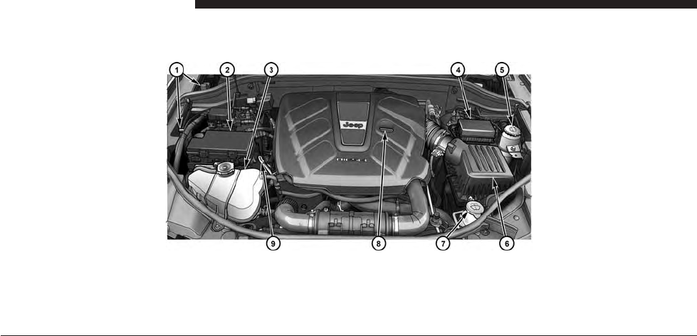
ENGINE COMPARTMENT — 3.0L DIESEL
1 — Remote Jump Start Location 6 — Air Cleaner Filter
2 — Power Distribution Center (Fuses) 7 — Washer Fluid Reservoir
3 — Engine Coolant Reservoir 8 — Engine Oil Fill
4 — Integrated Power Module (Fuses) 9 — Engine Oil Dipstick
5 — Power Steering Fluid Reservoir
72 MAINTAINING YOUR VEHICLE
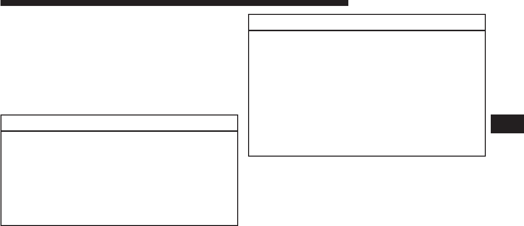
MAINTENANCE PROCEDURES
The pages that follow contain the required maintenance
services determined by the engineers who designed your
vehicle.
Besides those maintenance items specified in the fixed
maintenance schedule, there are other components which
may require servicing or replacement in the future.
CAUTION!
•Failure to properly maintain your vehicle or per-
form repairs and service when necessary could
result in more costly repairs, damage to other
components or negatively impact vehicle perfor-
mance. Immediately have potential malfunctions
examined by an authorized Chrysler Group LLC
dealership or qualified repair center.
(Continued)
CAUTION! (Continued)
•Your vehicle has been built with improved fluids
that protect the performance and durability of your
vehicle and also allow extended maintenance inter-
vals. Do not use chemical flushes in these compo-
nents as the chemicals can damage your engine,
transmission, power steering or air conditioning.
Such damage is not covered by the New Vehicle
Limited Warranty. If a flush is needed because of
component malfunction, use only the specified
fluid for the flushing procedure.
5
MAINTAINING YOUR VEHICLE 73
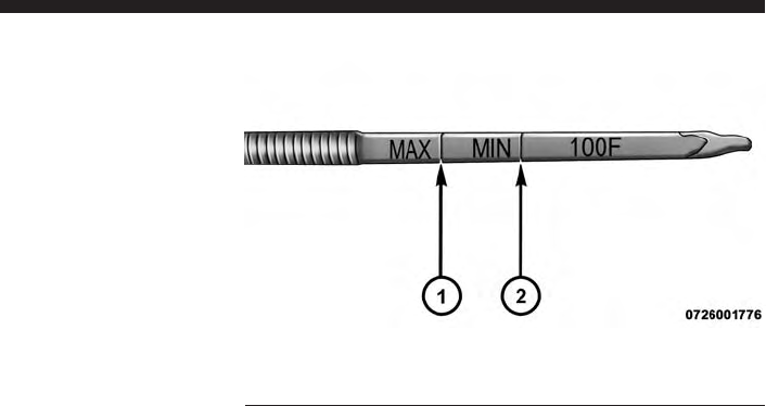
Engine Oil
Engine Oil Selection
For best performance and maximum protection under all
types of operating conditions, the manufacturer recom-
mends engine oils that meet the requirements of Chrysler
Material Standard MS-11106, and that are approved to
Fiat 9.55535-S1 or Fiat 9.55535-S3 and ACEA C3.
Checking Oil Level
To assure proper lubrication of your vehicle’s engine, the
engine oil must be maintained at the correct level. Check
the oil level at regular intervals. The best time to check
the oil level is before starting the engine after it has been
parked overnight. When checking oil after operating the
engine, first ensure the engine is at full operating tem-
perature, then wait for 30 minutes after engine shutdown
to check the oil.
1 — MAX Mark
2 — MIN Mark
74 MAINTAINING YOUR VEHICLE
Checking the oil while the vehicle is on level ground will
improve the accuracy of the oil level readings. Add oil
only when the level on the dipstick is below the “MIN”
mark. The total capacity from the MIN mark to the MAX
mark is 1.7 qts (1.6L).
CAUTION!
Overfilling or underfilling the crankcase will cause
oil aeration or loss of oil pressure. This could damage
your engine.
NOTE: It is possible for your oil level to be slightly
higher than a previous check. This would be due to diesel
fuel that may temporarily be in the crankcase due to
operation of the diesel particulate filter regeneration
strategy. This fuel will evaporate out under normal
operation.
Never operate the engine with oil level below the “MIN”
mark or above the upper “MAX” mark.
Change Engine Oil
Refer to the “Maintenance Schedule” for the proper
maintenance intervals.
Engine Oil Viscosity (SAE Grade)
CAUTION!
Your vehicle is equipped with an advanced technol-
ogy Diesel Engine and an emission device designed
to limit Diesel Particulate Emissions from being
released into the atmosphere. The durability of your
engine and life expectancy of this diesel particulate
filter emission device is highly dependent on the use
of the correct engine oil.
5
MAINTAINING YOUR VEHICLE 75

Only use ACEA C3 SAE 5W-30 Synthetic Low Ash engine
oil meeting Chrysler material standard MS-11106 or
Pennzoil Ultra Euro L full synthetic 5W-30 motor oil,
which is recommended for all operating temperatures.
This engine oil improves low temperature starting and
vehicle fuel economy.
Materials Added To Engine Oil
The manufacturer strongly recommends against the ad-
dition of any additives (other than leak detection dyes) to
the engine oil. Engine oil is an engineered product and its
performance may be impaired by supplemental addi-
tives.
Engine Oil Filter
Refer to “Fluids, Lubricants, and Genuine Parts” in
“Maintaining Your Vehicle” for further information. The
engine oil filter should be changed at every engine oil
change.
Disposing Of Used Engine Oil And Oil Filters
Care should be taken in disposing of used engine oil and
oil filters from your vehicle. Used oil and oil filters,
indiscriminately discarded, can present a problem to the
environment. Contact your authorized dealer, service
station or governmental agency for advice on how and
where used oil and oil filters can be safely discarded in
your area.
76 MAINTAINING YOUR VEHICLE
Engine Air Cleaner Filter
Refer to the “Maintenance Schedule” for the proper
maintenance intervals.
CAUTION!
All air entering the engine intake must be filtered.
The abrasive particles in unfiltered air will cause
rapid wear to engine components.
WARNING!
The air induction system (air cleaner, hoses, etc.)
provides a measure of protection. Do not remove the
air induction system (air cleaner, hoses, etc.) unless
such removal is necessary for repair or maintenance.
(Continued)
WARNING! (Continued)
Make sure that no one is near the engine compart-
ment before starting the vehicle with the air induc-
tion system (air cleaner, hoses, etc.) removed. Failure
to do so can result in serious personal injury.
CAUTION!
Many aftermarket performance air filter elements do
not adequately filter the air entering the engine. Use
of such filters can severely damage your engine.
Engine Air Cleaner Filter Selection
The quality of replacement engine air cleaner filters varies
considerably. Only high quality filters should be used to
assure most efficient service. MOPAR® engine air cleaner
filters are a high quality filter and are recommended.
5
MAINTAINING YOUR VEHICLE 77
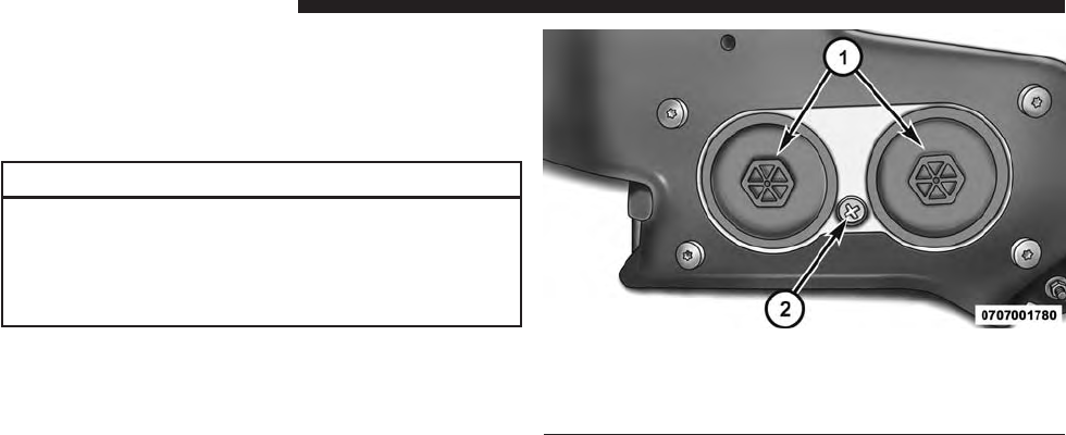
Draining Fuel/Water Separator Filter
The fuel filter/water separator housing is located on the
left side of the vehicle in front of the fuel tank. The best
access to this water drain valve is from under the vehicle.
CAUTION!
•Do not drain the fuel/water separator filters when
the engine is running.
•Diesel fuel will damage blacktop paving surfaces.
Drain the filters into an appropriate container.
If water is detected in the water separator while the
engine is running, or while the ignition switch is in the
ON position, the “Water In Fuel Indicator Light” will
illuminate and an audible chime will be heard. At this
point you should stop the engine and drain the water
from the filter housing.
1 — Fuel Filter Access
2 — Water in Fuel Drain
Fuel Filter Assembly
78 MAINTAINING YOUR VEHICLE

CAUTION!
If the “Water In Fuel Indicator Light” remains on, DO
NOT START the engine before you drain water from
the fuel filters to avoid engine damage.
If the “Water In Fuel Indicator Light” comes on and a
single chime are heard while you are driving, or with the
ignition in the ON position, there may be a problem with
your water separator wiring or sensor. See your autho-
rized dealer for service.
Upon proper draining of the water from fuel filter
assembly, the “Water In Fuel Indicator Light” will remain
illuminated for approximately 10 seconds. If the water
was drained while the engine was running, the “Water In
Fuel Indicator Light” may remain on for approximately
three minutes.
NOTE: Care should be taken in disposing of used fluids
from your vehicle. Used fluids, indiscriminately dis-
carded, can present a problem to the environment. Con-
tact an authorized dealer, service station, or government
agency for advice on recycling programs and for where
used fluids and filters can be properly disposed of in
your area.
Drain the fuel/water separator filters when the “Water In
Fuel Indicator Light” is ON. Within 10 minutes of vehicle
shutdown, turn the filter drain valve (located on the
bottom of the filter housing) counterclockwise to drain
fuel/water, then turn the ignition switch to the ON
position, and allow any accumulated water to drain.
Leave the drain valve open until all water and contami-
nants have been removed. When clean fuel is visible,
close the drain valve by turning it clockwise, and turn the
ignition switch to OFF.
5
MAINTAINING YOUR VEHICLE 79
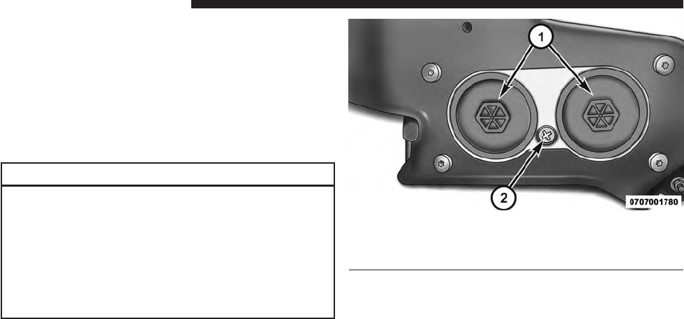
If more than two ounces or 60 milliliters of fuel have been
drained, follow the directions for “Priming If The Engine
Has Run Out Of Fuel.”
Underbody Mounted Fuel Filter Replacement
NOTE: Using a fuel filter that does not meet the manu-
facturer’s filtration and water separating requirements
can severely impact fuel system life and reliability.
CAUTION!
•Diesel fuel will damage blacktop paving surfaces.
Drain the filter into an appropriate container.
•Do not prefill the fuel filter when installing a new
fuel filter. There is a possibility debris could be
introduced into the fuel filter during this action. It
is best to install the filter dry and allow the in-tank
lift pump to prime the fuel system.
1 — Fuel Filter Access
2 — Water in Fuel Drain
1. Ensure engine is turned off.
2. Place drain pan under the fuel filter assembly.
Fuel Filter Assembly
80 MAINTAINING YOUR VEHICLE

3. Open the water drain valve, and let any accumulated
water drain.
4. Close the water drain valve.
5. Remove using a socket. Rotate counterclockwise for
removal. Remove used o-ring and discard it.
6. Remove the used filter cartridge from the housing and
dispose of according to your local regulations.
7. Wipe clean the sealing surfaces of the lid and housing.
8. Install new o-ring back into ring groove on the filter
housing and lubricate with clean engine oil.
9. Repeat steps 5 through 8 to service second filter in fuel
filter assembly.
NOTE: WIF (Water In Fuel) sensor is re-usable. Service
kit comes with new o-ring for filter canister and WIF
sensor.
Priming If The Engine Has Run Out Of Fuel
WARNING!
Do not open the high pressure fuel system with the
engine running. Engine operation causes high fuel
pressure. High pressure fuel spray can cause serious
injury or death.
1. Add a substantial amount of fuel to the tank, approxi-
mately 2 to 5 gal (8L to 19L).
2. Press ignition switch twice without your foot on brake
to put vehicle in Run position. This will activate the in
tank fuel pump for approximately 30 seconds. Repeat
this process twice.
3. Start the engine using the “Normal Starting” proce-
dure. Refer to “Starting Procedures” in “Starting and
Operating” for further information.
5
MAINTAINING YOUR VEHICLE 81
CAUTION!
The starter motor will engage for approximately
30 seconds at a time. Allow two minutes between the
cranking intervals.
NOTE: The engine may run rough until the air is forced
from all the fuel lines.
WARNING!
Do not use alcohol or gasoline as a fuel blending
agent. They can be unstable under certain conditions
and be hazardous or explosive when mixed with
diesel fuel.
CAUTION!
Due to lack of lubricants in alcohol or gasoline, the
use of these fuels can cause damage to the fuel
system.
NOTE:
•We recommend you use a blend of up to 5% biodiesel,
that meets ASTM specification D-975 with your diesel
engine. Use of biodiesel mixture in excess of 20% can
negatively impact the fuel filter’s ability to separate
water from the fuel, resulting in high pressure fuel
system corrosion or damage.
•In addition, commercially available fuel additives are
not necessary for the proper operation of your diesel
engine.
82 MAINTAINING YOUR VEHICLE

Intervention Regeneration Strategy — EVIC
Message Process Flow
This engine meets all required diesel engine emissions
standards. To achieve these emissions standards, your
vehicle is equipped with a state-of-the-art engine and
exhaust system. These systems are seamlessly integrated
into your vehicle and managed by the Powertrain Con-
trol Module (PCM). The PCM manages engine combus-
tion to allow the exhaust system’s catalyst to trap and
burn Particulate Matter (PM) pollutants, with no input or
interaction on your part.
Additionally, your vehicle has the ability to alert you to
additional maintenance required on your vehicle or engine.
Refer to “Electronic Vehicle Information Center (EVIC)”
in “Understanding Your Instrument Panel” for further
information.
WARNING!
A hot exhaust system can start a fire if you park over
materials that can burn. Such materials might be
grass or leaves coming into contact with your exhaust
system. Do not park or operate your vehicle in areas
where your exhaust system can contact anything that
can burn.
5
MAINTAINING YOUR VEHICLE 83
Maintenance-Free Batteries
Your vehicle is equipped with a maintenance-free battery.
The top of the maintenance-free battery is permanently
sealed. You will never have to add water, nor is periodic
maintenance required.
CAUTION!
It is essential when replacing the cables on the
battery that the positive cable is attached to the
positive post and the negative cable is attached to the
negative post. Battery posts are marked (+) positive
and negative (-) and are identified on the battery
case. Also, if a “fast charger” is used while the battery
is in vehicle, disconnect both vehicle battery cables
before connecting the charger to the battery. Do not
use a “fast charger” to provide starting voltage.
WARNING!
Battery posts, terminals, and related accessories con-
tain lead and lead compounds. Always wash hands
after handling the battery.
Cooling System
WARNING!
You or others can be badly burned by hot engine
coolant (antifreeze) or steam from your radiator. If
you see or hear steam coming from under the hood,
do not open the hood until the radiator has had time
to cool. Never try to open a cooling system pressure
cap when the radiator is hot.
84 MAINTAINING YOUR VEHICLE

Engine Coolant Checks
Check the engine coolant (antifreeze) protection every
12 months (before the onset of freezing weather, where
applicable). If the engine coolant (antifreeze) is dirty or
rusty in appearance, the system should be drained,
flushed and refilled with fresh coolant. Check the front of
the A/C condenser (if equipped) or radiator for any
accumulation of bugs, leaves, etc. If dirty, clean by gently
spraying water from a garden hose vertically down the
face of the A/C condenser (if equipped) or the back of the
radiator core.
Check the engine cooling system hoses for brittle rubber,
cracking, tears, cuts and tightness of the connection at the
coolant recovery bottle and radiator. Inspect the entire
system for leaks.
With the engine at normal operating temperature (but
not running), check the cooling system pressure cap for
proper vacuum sealing by draining a small amount of
engine coolant (antifreeze) from the radiator drain cock.
The radiator drain cock is located in the lower radiator
tank. If the cap is sealing properly, the engine coolant
(antifreeze) will begin to drain from the coolant expan-
sion bottle. DO NOT REMOVE THE COOLANT PRES-
SURE CAP WHEN THE COOLING SYSTEM IS HOT.
Cooling System — Drain Flush And Refill
If the engine coolant (antifreeze) is dirty or contains a
considerable amount of sediment, clean and flush with a
reliable cooling system cleaner. Follow with a thorough
rinsing to remove all deposits and chemicals. Properly
dispose of old engine coolant (antifreeze).
Refer to the “Maintenance Schedule” for the proper
maintenance intervals.
5
MAINTAINING YOUR VEHICLE 85
Selection Of Coolant
Refer to “Fluids, Lubricants, and Genuine Parts” in
“Maintaining Your Vehicle” for further information.
CAUTION!
•Mixing of engine coolant (antifreeze) other than
specified Organic Additive Technology (OAT) en-
gine coolant (antifreeze), may result in engine
damage and may decrease corrosion protection.
Organic Additive Technology (OAT) engine cool-
ant is different and should not be mixed with
Hybrid Organic Additive Technology (HOAT) en-
gine coolant (antifreeze) or any “globally compat-
ible” coolant (antifreeze). If a non-OAT engine
coolant (antifreeze) is introduced into the cooling
system in an emergency, the cooling system will
(Continued)
CAUTION! (Continued)
need to be drained, flushed, and refilled with fresh
OAT coolant (conforming to MS-12106), by an
authorized dealer as soon as possible.
•Do not use water alone or alcohol-based engine
coolant (antifreeze) products. Do not use additional
rust inhibitors or antirust products, as they may not
be compatible with the radiator engine coolant and
may plug the radiator.
•This vehicle has not been designed for use with
propylene glycol-based engine coolant (antifreeze).
Use of propylene glycol-based engine coolant (an-
tifreeze) is not recommended.
86 MAINTAINING YOUR VEHICLE

Adding Coolant
Your vehicle has been built with an improved engine
coolant (OAT coolant conforming to MS-12106) that allows
extended maintenance intervals. This engine coolant (anti-
freeze) can be used up to ten years or 150,000 miles
(240,000 km) before replacement. To prevent reducing this
extended maintenance period, it is important that you use
the same engine coolant (OAT coolant conforming to
MS-12106) throughout the life of your vehicle.
Please review these recommendations for using Organic
Additive Technology (OAT) engine coolant (antifreeze)
that meets the requirements of Chrysler Material Stan-
dard MS-12106. When adding engine coolant (antifreeze):
•We recommend using MOPAR® Antifreeze/Coolant
10 Year/150,000 Mile Formula OAT (Organic Additive
Technology) that meets the requirements of Chrysler
Material Standard MS-12106.
•Mix a minimum solution of 50% OAT engine coolant
that meets the requirements of Chrysler Material Stan-
dard MS-12106 and distilled water. Use higher concen-
trations (not to exceed 70%) if temperatures below
−34° F (−37° C) are anticipated.
•Use only high purity water such as distilled or deion-
ized water when mixing the water/engine coolant
(antifreeze) solution. The use of lower quality water
will reduce the amount of corrosion protection in the
engine cooling system.
Please note that it is the owner’s responsibility to main-
tain the proper level of protection against freezing ac-
cording to the temperatures occurring in the area where
the vehicle is operated.
5
MAINTAINING YOUR VEHICLE 87
NOTE:
•Some vehicles require special tools to add coolant
properly. Failure to fill these systems properly could
lead to severe internal engine damage. If any coolant is
needed to be added to the system please contact your
local authorized dealer.
•Mixing engine coolant (antifreeze) types is not recom-
mended and can result in cooling system damage. If
HOAT and OAT coolant are mixed in an emergency,
have a authorized dealer drain, flush, and refill with
OAT coolant (conforming to MS-12106) as soon as
possible.
Cooling System Pressure Cap
The cap must be fully tightened to prevent loss of engine
coolant (antifreeze), and to ensure that the engine coolant
(antifreeze) will return to the radiator from the coolant
expansion bottle.
The cap should be inspected and cleaned if there is any
accumulation of foreign material on the sealing surfaces.
WARNING!
•
The warning words “DO NOT OPEN HOT” on the
cooling system pressure cap are a safety precaution.
Never add engine coolant (antifreeze) when the
engine is overheated. Do not loosen or remove the
cap to cool an overheated engine. Heat causes pres-
sure to build up in the cooling system. To prevent
scalding or injury, do not remove the pressure cap
while the system is hot or under pressure.
•
Do not use a pressure cap other than the one speci-
fied for your vehicle. Personal injury or engine
damage may result.
88 MAINTAINING YOUR VEHICLE

Disposal Of Used Engine Coolant
Used ethylene glycol-based engine coolant (antifreeze) is
a regulated substance requiring proper disposal. Check
with your local authorities to determine the disposal
rules for your community. To prevent ingestion by ani-
mals or children, do not store ethylene glycol-based
engine coolant (antifreeze) in open containers or allow it
to remain in puddles on the ground. If ingested by a child
or pet, seek emergency assistance immediately. Clean up
any ground spills immediately.
Points To Remember
NOTE: When the vehicle is stopped after a few miles/
kilometers of operation, you may observe vapor coming
from the front of the engine compartment. This is nor-
mally a result of moisture from rain, snow, or high
humidity accumulating on the radiator and being vapor-
ized when the thermostat opens, allowing hot engine
coolant (antifreeze) to enter the radiator.
If an examination of your engine compartment shows
no evidence of radiator or hose leaks, the vehicle may be
safely driven. The vapor will soon dissipate.
•Do not overfill the coolant expansion bottle.
•Check the coolant freeze point in the radiator and
in the coolant expansion bottle. If engine coolant
(antifreeze) needs to be added, the contents of the
coolant expansion bottle must also be protected
against freezing.
•If frequent engine coolant (antifreeze) additions are
required, the cooling system should be pressure tested
for leaks.
5
MAINTAINING YOUR VEHICLE 89

•Maintain engine coolant (antifreeze) concentration at
a minimum of 50% OAT coolant (conforming to
MS-12106) and distilled water for proper corrosion
protection of your engine which contains aluminum
components.
•Make sure that the coolant expansion bottle overflow
hoses are not kinked or obstructed.
•Keep the front of the radiator clean. If your vehicle is
equipped with air conditioning, keep the front of the
condenser clean.
•
Do not change the thermostat for Summer or Winter
operation. If replacement is ever necessary, install ONLY
the correct type thermostat. Other designs may result in
unsatisfactory engine coolant (antifreeze) performance,
poor gas mileage, and increased emissions.
Charge Air Cooler — Inter-Cooler
The charge air cooler is positioned in front of the radiator
and the air conditioner condenser. Air enters the engine
through the air cleaner and passes through the turbo-
charger, where it is pressurized. This pressurized air
rapidly reaches high temperature. The air is then directed
through a hose to the charge air cooler and through
another hose to the intake manifold of the engine. This
cooling process enables more efficient burning of fuel
resulting in fewer emissions.
To guarantee optimum performance of the system, keep
the surfaces of the charge air cooler, condenser and
radiator clean and free of debris. Periodically check the
hoses leading to and from the charge air cooler for cracks
or loose clamps resulting in loss of pressure and reduced
engine performance.
90 MAINTAINING YOUR VEHICLE

Brake System
Brake Master Cylinder — Brake Fluid Level Check
The fluid level of the master cylinder should be checked
when performing under the hood service, or immedi-
ately if the “Brake System Warning Light” indicates
system failure.
The brake master cylinder has a translucent plastic
reservoir. On the outboard side of the reservoir, there is a
“MAX” mark and a “MIN” mark. The fluid level must be
kept within these two marks. Do not add fluid above the
full mark because leakage may occur at the cap.
With disc brakes, the fluid level can be expected to fall as
the brake linings wear. However, an unexpected drop in
fluid level may be caused by a leak and a system check
should be conducted.
Refer to “Fluids, Lubricants, and Genuine Parts” in
“Maintaining Your Vehicle” for further information.
WARNING!
•Use only manufacturer’s recommended brake
fluid. Refer to “Fluids, Lubricants, and Genuine
Parts” in “Maintaining Your Vehicle” for further
information. Using the wrong type of brake fluid
can severely damage your brake system and/or
impair its performance. The proper type of brake
fluid for your vehicle is also identified on the
original factory installed hydraulic master cylinder
reservoir.
(Continued)
5
MAINTAINING YOUR VEHICLE 91
WARNING! (Continued)
•To avoid contamination from foreign matter or
moisture, use only new brake fluid or fluid that has
been in a tightly closed container. Keep the master
cylinder reservoir cap secured at all times. Brake
fluid in a open container absorbs moisture from the
air resulting in a lower boiling point. This may
cause it to boil unexpectedly during hard or pro-
longed braking, resulting in sudden brake failure.
This could result in a accident.
(Continued)
WARNING! (Continued)
•Overfilling the brake fluid reservoir can result in
spilling brake fluid on hot engine parts, causing
the brake fluid to catch fire. Brake fluid can also
damage painted and vinyl surfaces, care should be
taken to avoid its contact with these surfaces.
•Do not allow petroleum based fluid to contaminate
the brake fluid. Brake seal components could be
damaged, causing partial or complete brake failure.
This could result in an accident.
92 MAINTAINING YOUR VEHICLE
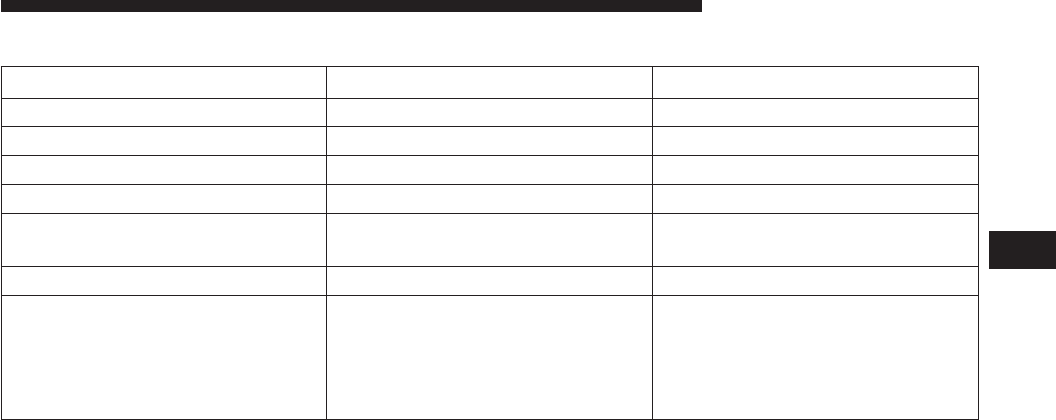
FLUID CAPACITIES
U.S. Metric
Fuel (Approximate)
3.0L Diesel Engine 24.6 Gallons 93.1 Liters
Diesel Exhaust Fluid Tank 8 Gallons 30.3 Liters
Engine Oil With Filter
3.0 Liter Diesel Engine (SAE 5W-30
Synthetic, API Certified Low Ash)
8 Quarts 7.7 Liters
Cooling System
3.0L Turbo Diesel Engine
(MOPAR® Engine Coolant/
Antifreeze 10 Year/150,000 Mile
Formula OAT (Organic Additive
Technology))
12 Quarts 11.4 Liters
5
MAINTAINING YOUR VEHICLE 93
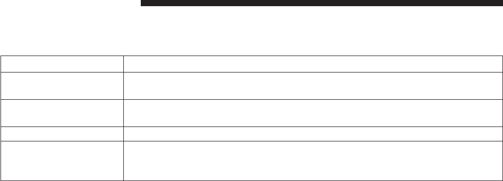
FLUIDS, LUBRICANTS AND GENUINE PARTS
Engine
Component Fluid, Lubricant, or Genuine Part
Engine Coolant We recommend you use MOPAR® Antifreeze/Coolant 10 Year/150,000 Mile Formula
OAT (Organic Additive Technology).
Engine Oil Only use ACEA C3 5W-30 Synthetic Low Ash engine oil meeting Chrysler material
standard MS-11106 or Pennzoil Ultra Euro L full synthetic 5W-30 motor oil.
Engine Oil Filter We recommend you use MOPAR® Engine Oil Filters.
Fuel Filters We recommend you use MOPAR® Fuel Filter. Must meet 3 micron rating. Using a fuel
filter that does not meet the manufacturers filtration and water separating require-
ments can severely impact fuel system life and reliability.
94 MAINTAINING YOUR VEHICLE

Component Fluid, Lubricant, or Genuine Part
Fuel Selection Use good quality diesel fuel from a reputable supplier in your vehicle. Federal law
requires that you must fuel this vehicle with Ultra Low Sulfur Highway Diesel fuel
(15 ppm Sulfur maximum) and prohibits the use of Low Sulfur Highway Diesel fuel
(500 ppm Sulfur maximum) to avoid damage to the emissions control system. For
most year-round service, No. 2 diesel fuel meeting ASTM specification D-975 Grade
S15 will provide good performance. We recommend you use a blend of up to 5%
biodiesel, meeting ASTM specification D-975 with your diesel engine.This vehicle is
compatible with biodiesel blends greater than 5% but no greater than 20% biodiesel
meeting ASTM specification D-7467 provided the shortened maintenance intervals
are followed as directed.
Diesel Exhaust Fluid MOPAR® Diesel Exhaust Fluid (API Certified) (DEF) or equivalent that has been API
Certified to the ISO 22241 standard. Use of fluids not API Certified to ISO 22241 may
result in system damage.
NOTE: If the vehicle is exposed to extreme cold (below
20°F or -7°C), or is required to operate at colder-than-
normal conditions for prolonged periods, use climatized
No. 2 diesel fuel or dilute the No. 2 diesel fuel with 50%
No. 1 diesel fuel. This will provide better protection from
fuel gelling or wax-plugging of the fuel filters.
5
MAINTAINING YOUR VEHICLE 95

Chassis
Component Fluid, Lubricant, or Genuine Part
Automatic Transmission We recommend you only use Mopar® ZF 8&9 Speed
ATF™ Automatic Transmission Fluid. Failure to use the
correct fluid may affect the function or performance of
your transmission.
Transfer Case – Single-Speed (Quadra-Trac I®) We recommend you use Shell Automatic Transmission
Fluid 3353.
Transfer Case – Two-Speed (Quadra-Trac II®) We recommend you use MOPAR® ATF+4® Automatic
Transmission Fluid.
Axle Differential (Front) We recommend you use MOPAR® GL-5 Synthetic Axle
Lubricant SAE 75W-85.
96 MAINTAINING YOUR VEHICLE

Component Fluid, Lubricant, or Genuine Part
Axle Differential (Rear) – With Electronic Limited-Slip
Differential (ELSD)
We recommend you use MOPAR® GL-5 Synthetic Axle
Lubricant SAE 75W-85 with friction modifier additive.
Axle Differential (Rear) – Without Electronic Limited-
Slip Differential (ELSD)
We recommend you use MOPAR® GL-5 Synthetic Axle
Lubricant SAE 75W-85.
Brake Master Cylinder We recommend you use MOPAR® DOT 3 Brake Fluid,
SAE J1703 should be used. If DOT 3, SAE J1703 brake
fluid is not available, then DOT 4 is acceptable.
Power Steering Reservoir – 3.0L Engine We recommend you use MOPAR® Hydraulic fluid
MS-11655.
5
MAINTAINING YOUR VEHICLE 97


MAINTENANCE SCHEDULE
Your vehicle is equipped with an automatic oil change
indicator system. The oil change indicator system will
remind you that it is time to take your vehicle in for
scheduled maintenance.
Based on engine operation conditions, the oil change
indicator message will illuminate. This means that ser-
vice is required for your vehicle. Operating conditions
such as frequent short-trips, trailer tow, extremely hot or
cold ambient temperatures will influence when the “Oil
Change Required” message is displayed. Severe Operat-
ing Conditions can cause the change oil message to
illuminate as early as 3,500 miles (5,600 km) since last
reset. Have your vehicle serviced as soon as possible,
within the next 500 miles (805 km).
Your authorized dealer will reset the oil change indicator
message after completing the scheduled oil change. If a
scheduled oil change is performed by someone other
than your authorized dealer, the message can be reset by
referring to the steps described under “Electronic Vehicle
Information Center (EVIC)/Oil Change Required” in
“Understanding Your Instrument Panel” for further in-
formation
NOTE: Under no circumstances should oil change inter-
vals exceed 10,000 miles (16,000 km) or twelve months,
whichever comes first.
Engine Oil Filter Replacement
Residual oil in the housing may spill from the housing
when the new filter is installed if the residual oil is not
either removed from the housing or enough time has not
elapsed to allow the oil to drain back into the engine.
When servicing the oil filter on this engine, carefully
remove the filter and use a suction gun to remove any
residual oil left in the housing or wait about 30 minutes
for the oil to drain back into the engine.
100 MAINTENANCE SCHEDULE

Once A Month Or Before A Long Trip:
•Check engine oil level
•Check windshield washer fluid level
•Check the tire inflation pressures and look for unusual
wear or damage
•Check the fluid levels of the coolant reservoir, brake
master cylinder, power steering and transmission as
needed
•Check function of all interior and exterior lights
Required Maintenance
Refer to the Maintenance Schedules on the following
pages for required maintenance.
At Every Oil Change Interval As Indicated By Oil
Change Indicator System:
•Change oil and filter.
•Completely fill the Diesel Exhaust Fluid tank.
•Rotate the tires. Rotate at the first sign of irregu-
lar wear, even if it occurs before the oil indicator
system turns on.
•Inspect battery and clean and tighten terminals as
required.
•Inspect automatic transmission fluid if equipped
with dipstick.
•Inspect brake pads, shoes, rotors, drums, hoses
and park brake.
•
Inspect engine cooling system protection and hoses.
•Inspect exhaust system.
•Inspect engine air cleaner if using in dusty or
off-road conditions.
6
MAINTENANCE SCHEDULE 101
Maintenance Chart — Diesel Fuel Up To B5 Biodiesel
Mileage or time passed (whichever comes first)
10,000
20,000
30,000
40,000
50,000
60,000
70,000
80,000
90,000
100,000
110,000
120,000
130,000
140,000
150,000
Or Years: 1 2 3 4 5 6 7 8 9 10 11 12 13 14 15
Or Kilometers:
16,000
32,000
48,000
64,000
80,000
96,000
112,000
128,000
144,000
160,000
176,000
192,000
208,000
224,000
240,000
Additional Inspections
Completely fill the Diesel Exhaust Fluid tank. X X X X X X X X X X X X X X X
Inspect the CV joints. X X X X X
Inspect front suspension, tie rod ends, and replace if
necessary. XXXXXXX
Inspect the front and rear axle fluid, change if using
your vehicle for police, taxi, fleet, off-road or frequent
trailer towing. XXXXXXX
Inspect the brake linings, parking brake function. X X X X X X X
Inspect transfer case fluid. X X X X
102 MAINTENANCE SCHEDULE

Mileage or time passed (whichever comes first)
10,000
20,000
30,000
40,000
50,000
60,000
70,000
80,000
90,000
100,000
110,000
120,000
130,000
140,000
150,000
Or Years: 1 2 3 4 5 6 7 8 9 10 11 12 13 14 15
Or Kilometers:
16,000
32,000
48,000
64,000
80,000
96,000
112,000
128,000
144,000
160,000
176,000
192,000
208,000
224,000
240,000
Additional Maintenance
Replace fuel filters and drain water from the fuel filter
assembly. XXXXX
Replace engine air filter. X X X X X
Replace the air conditioning filter. X X X X X X X
Flush and replace the engine coolant at 10 years or
150,000 miles (240,000 km) whichever comes first. XX
Replace accessory drive belt(s). X
Change transfer case fluid. X
6
MAINTENANCE SCHEDULE 103

WARNING!
•You can be badly injured working on or around a
motor vehicle. Do only service work for which you
have the knowledge and the right equipment. If
you have any doubt about your ability to perform a
service job, take your vehicle to a competent me-
chanic.
•Failure to properly inspect and maintain your ve-
hicle could result in a component malfunction and
effect vehicle handling and performance. This
could cause an accident.
MAINTENANCE SCHEDULE — B6 To B20
Biodiesel
NOTE:
•Under no circumstances should oil change intervals
exceed 8,000 miles (12 875 km) or six months, which-
ever comes first when using Biodiesel blends greater
than 5% (B5).
•The owner is required to monitor mileage for B6-B20
biodiesel, the automatic oil change indicator system
does not reflect the use of biofuels.
104 MAINTENANCE SCHEDULE

Once A Month Or Before A Long Trip:
•Check engine oil level
•Check windshield washer fluid level
•Check the tire inflation pressures and look for unusual
wear or damage
•Check the fluid levels of the coolant reservoir, brake
master cylinder, power steering and transmission as
needed
•Check function of all interior and exterior lights
Required Maintenance
Refer to the Maintenance Schedules on the following
pages for required maintenance.
At Every Oil Change Interval As Indicated By Oil
Change Indicator System:
•Change oil and filter.
•Completely fill the Diesel Exhaust Fluid tank.
•Rotate the tires. Rotate at the first sign of irregu-
lar wear, even if it occurs before the oil indicator
system turns on.
•Inspect battery and clean and tighten terminals as
required.
•Inspect automatic transmission fluid if equipped
with dipstick.
•Inspect brake pads, shoes, rotors, drums, hoses
and park brake.
•
Inspect engine cooling system protection and hoses.
•Inspect exhaust system.
•Inspect engine air cleaner if using in dusty or
off-road conditions.
6
MAINTENANCE SCHEDULE 105

Maintenance Chart — B6 to B20 Biodiesel
Mileage or time passed (whichever comes first)
10,000
20,000
30,000
40,000
50,000
60,000
70,000
80,000
90,000
100,000
110,000
120,000
130,000
140,000
150,000
Or Years: 1 2 3 4 5 6 7 8 9 10 11 12 13 14 15
Or Kilometers:
16,000
32,000
48,000
64,000
80,000
96,000
112,000
128,000
144,000
160,000
176,000
192,000
208,000
224,000
240,000
Additional B6 to B20 Maintenance
Replace fuel filters and drain water from the fuel filter
assembly. XXXX XX X
106 MAINTENANCE SCHEDULE

WARNING!
•You can be badly injured working on or around a
motor vehicle. Do only service work for which you
have the knowledge and the right equipment. If
you have any doubt about your ability to perform a
service job, take your vehicle to a competent me-
chanic.
•Failure to properly inspect and maintain your ve-
hicle could result in a component malfunction and
effect vehicle handling and performance. This
could cause an accident.
6
MAINTENANCE SCHEDULE 107

INDEX
7

Adding Engine Coolant (Antifreeze).............87
Adding Fuel..............................63
Airbag Light .............................19
Air Cleaner, Engine (Engine Air Cleaner Filter) .....77
Antifreeze (Engine Coolant)...................86
Capacities .............................93
Disposal ..............................89
Anti-Lock Warning Light .....................11
Automatic Transmission
Fluid Type .............................96
Axle Fluid ...............................96
Battery .................................84
Brake Fluid ..............................96
Brake System .............................91
Fluid Check ............................91
Master Cylinder .........................91
Warning Light ..........................15
Capacities, Antifreeze (Engine Coolant)...........93
Capacities, Fluid...........................93
Caps, Filler
Oil (Engine) ............................75
Radiator (Coolant Pressure) .................88
Charge Air Cooler .........................90
Coolant Pressure Cap (Radiator Cap) ............88
Cooling System ...........................84
Adding Coolant (Antifreeze) ................87
Coolant Capacity ........................93
Coolant Level ...........................85
Disposal of Used Coolant ..................89
Drain, Flush, and Refill ....................85
Points to Remember ......................89
Pressure Cap ...........................88
Radiator Cap ...........................88
Selection of Coolant (Antifreeze) .............86
110 INDEX

Diesel Fuel...............................44
Diesel Fuel Requirements ....................44
Bulk Storage of .........................66
Diesel Fuel System, Re-Priming ................81
Disposal
Antifreeze (Engine Coolant) .................89
Draining Fuel/Water Separator Filter ............78
Electronic Vehicle Information Center (EVIC) ......18
Engine..................................72
Air Cleaner ............................77
Block Heater ...........................36
Break-In Recommendations ..................7
Compartment ...........................72
Coolant (Antifreeze) ......................94
Identification ...........................72
Idling ................................40
Oil ..................................74
Oil Filler Cap ...........................75
Temperature Gauge ......................14
Filters
Air Cleaner ............................77
Engine Fuel ............................78
Engine Oil .............................76
Engine Oil Disposal ......................76
Flashers
Turn Signal ............................12
Fluid, Brake ..............................96
Fluid Capacities ...........................93
Fluid Level Checks
Brake ................................91
Fluids, Lubricants and Genuine Parts ............94
Fog Lights ...............................12
7
INDEX 111

Fuel ...................................44
Adding ...............................63
Diesel ................................44
Filter .................................78
Gauge ................................16
Requirements ...........................44
Specifications ...........................45
Tank Capacity ..........................93
Fueling .................................63
Gauges
Coolant Temperature .....................14
Fuel .................................16
Speedometer ...........................12
Tachometer ............................11
Voltmeter ..............................39
Gross Axle Weight Rating ....................50
Gross Vehicle Weight Rating ..................49
High Beam Indicator........................12
Hitches
Trailer Towing ..........................52
Information Center, Vehicle ...................21
Instrument Cluster .........................10
Intervention Regeneration Strategy..............26
Lights
Airbag ................................19
Anti-Lock .............................11
Brake Warning ..........................15
Fog..................................12
High Beam Indicator ......................12
Malfunction Indicator (Check Engine) ..........12
Seat Belt Reminder .......................11
Security Alarm ..........................20
112 INDEX

Service Engine Soon (Malfunction Indicator) .....12
Tire Pressure Monitoring (TPMS) .............16
Maintenance Procedures .....................73
Maintenance Schedule ......................100
Malfunction Indicator Light (Check Engine) .......12
Manual Transmission
Lubricant Selection .......................96
New Vehicle Break-In Period ...................7
Odometer ...............................18
Trip..................................18
Oil, Engine...............................74
Capacity ..............................93
Change Interval .........................75
Dipstick ...............................74
Disposal ..............................76
Filter .................................76
Filter Disposal ..........................76
Materials Added to .......................76
Recommendation ........................74
Viscosity ..............................75
Overheating, Engine ........................14
Power Steering Fluid .......................96
Radiator Cap (Coolant Pressure Cap) ............85
Remote Starting System ......................6
Schedule, Maintenance .....................100
Seat Belts
Reminder ..............................11
Security Alarm ............................20
Selection of Coolant (Antifreeze) ...............94
Signals, Turn .............................12
Speedometer .............................12
7
INDEX 113

Starting .................................35
Automatic Transmission ...................36
Engine Block Heater ......................36
Remote ................................6
Starting Procedures.........................35
Starting Procedures (Diesel Engines).............35
Tachometer ..............................11
Temperature Gauge, Engine Coolant.............14
Tires
Pressure Warning Light ....................16
Trailer Towing ..........................57
Tongue Weight/Trailer Weight .................54
Towing .................................49
Guide ................................53
Weight ...............................53
Trailer Towing ............................49
Cooling System Tips ......................61
Hitches ...............................52
Minimum Requirements ...................55
Trailer and Tongue Weight .................54
Wiring ................................59
Trailer Towing Guide .......................53
Trailer Weight ............................53
Transfer Case
Fluid .................................96
Transmission
Fluid .................................96
Turn Signals..............................12
Viscosity, Engine Oil ........................75
Voltmeter................................39
Water Separator, Diesel Fuel ..................78
114 INDEX
INSTALLATION OF RADIO TRANSMITTING
EQUIPMENT
Special design considerations are incorporated into
this vehicle’s electronic system to provide immunity
to radio frequency signals. Mobile two-way radios
and telephone equipment must be installed prop-
erly by trained personnel. The following must be
observed during installation.
The positive power connection should be made
directly to the battery and fused as close to the
battery as possible. The negative power connection
should be made to body sheet metal adjacent to the
negative battery connection. This connection
should not be fused.
Antennas for two-way radios should be mounted on
the roof or the rear area of the vehicle. Care should
be used in mounting antennas with magnet bases.
Magnets may affect the accuracy or operation of
the compass on vehicles so equipped.
The antenna cable should be as short as practical
and routed away from the vehicle wiring when pos-
sible. Use only fully shielded coaxial cable.
Carefully match the antenna and cable to the radio
to ensure a low Standing Wave Ratio (SWR).
Mobile radio equipment with output power greater
than normal may require special precautions.
All installations should be checked for possible in-
terference between the communications equip-
ment and the vehicle’s electronic systems.
1283259cv1 14WK741-126-AA Grand Cherokee Chrysler 1" gutter 12/05/2012 15:56:03
Grand Cherokee
Chrysler Group LLC
OWNER’S MANUAL
2014 Grand Cherokee
14WK741-126-AA Second Edition Printed in U.S.A.
2014
Grand Cherokee
Chrysler Group LLC
OWNER’S MANUAL
2014 Grand Cherokee
14WK741-126-AA Second Edition Printed in U.S.A.
2014
Grand Cherokee
Chrysler Group LLC
OWNER’S MANUAL
2014 Grand Cherokee
14WK741-126-AA Second Edition Printed in U.S.A.
2014
Grand Cherokee
Chrysler Group LLC
OWNER’S MANUAL
2014 Grand Cherokee
14WK741-126-AA Second Edition Printed in U.S.A.
2014
Grand Cherokee
Chrysler Group LLC
OWNER’S MANUAL
2014 Grand Cherokee
14WK741-126-AA Second Edition Printed in U.S.A.
2014
Grand Cherokee
OWNER’S MANUAL
2014 Grand Cherokee
14WK741-126-AA Second Edition Printed in U.S.A.
2014
COVER INCOVER IN
Chrysler Group LLC
14WK742-126-AF
Sixth Edition
Printed in U.S.A.
