Jehe Technology Development MIION2 Mother Board User Manual MI ION2
Shenzhen jiehe Technology Development Co.,Ltd. Mother Board MI ION2
UserManual.wiki
>
Jehe Technology Development
>
MIION2 User Manual
Giada MI-ION2 User Manual
Navigation menu
Upload a User Manual
Namespaces
Wiki Guide
HTML
PDF
Info
Views
User Manual
Discussion / Help
Navigation
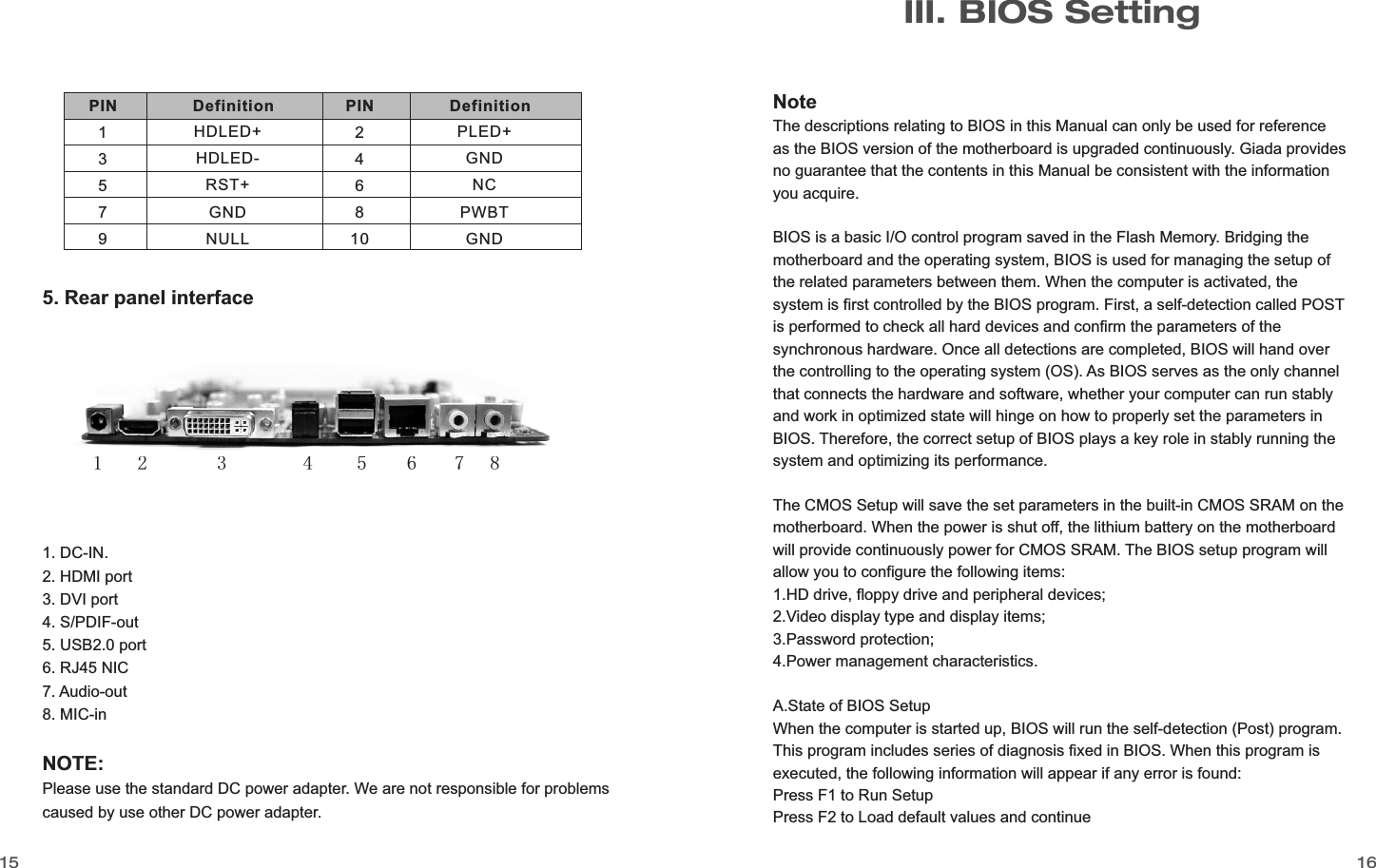
![1817Key↑ (Up key)↓ (Down key)← (Left key)→ (Right key)ESC Page UpPage DownF1F7F8F9F10FunctionMove to the previous item Move to the next itemMove to the left itemMove to the right itemExit the current interfaceChange the setup state, or add the valuesChange the setup state, or deduct the valuesDisplay the information of the current setupLoad the set values of previous timeLoad the safest valuesLoad the optimized valuesSave the settings and exit the CMOS SETUP C.C.Auxiliary informationMain interfaceWhen the system enters the main interface of Setup, the major selected contents will be displayed at the lower part of the interface with the change of the options.Set interfaceWhen you set the value for each column, you can view the preset value of thecolumn and the values that can be set if you press F1, for example, the BIOS default values or CMOS Setup values. To exit the interface for auxiliary information, press [ESC].To enter BIOS, you can press F1; to load the default values and enter the system, you can press F2. After the self-detection process is completed, you can press DEL to enter the BIOS interface if no error is found. If the indicative information disappears before you can act, you can shut off the computer and turn on it again, or you can press the key RESET on the machine case. To restart your computer, you can also simultaneously press <Ctrl>+<Alt>+<Delete>.B. Function Keys definitions1. Main menuWhen the system enters the CMOS Setup menu, you can see the main menu on the upper part of the screen, as shown in Figure 3.1. In this main menu, you can use the left and right direction keys to select the setup items. Once the item is selected, the lower part of the computer screen will show the details of setting.(The options above and their contents may be different from your actual options, so they are used for reference only).· Main (standard CMOS setup) This item is used for setting the date, time, specifications of hard disk and floppy disk and type of monitor.· Advanced (advanced BIOS setup) This item is used for setting the advanced functions provided by BIOS, such as the virus alarm and priority order of disks for startup process.Fig 3.1www.giadatech.com](https://usermanual.wiki/Jehe-Technology-Development/MIION2/User-Guide-1370496-Page-10.png)
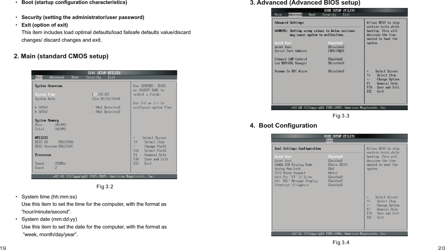
![2221Quick Boot If this item is set as Enabled, the system can be started within five seconds and some detection items will be ignored. The options are [Disabled] and [Enabled].Quiet Boot To start the system quietly.Add On ROM Display Mode [Force BIOS] This item allows you to set the display mode of the device's firmware program. The options are [Force BIOS] and [Keep Current].Bootup Num-Lock (To set the state of Num Lock after start-up). Options are OFF and ON. In other words, this item can be used for setting the state of Num Lock for the time the system has been started. It can be set on the basis of the needs of the user anddoesn't affect the performance of the computer.PS2 Mouse Support Set to support PS2 mouse. The available options are [Auto] and [Disable]. The default value is Auto.Wait For“F1” If any Error (The system waits the user to press F1 if any error occurs from the computer). The options are Disable and Enable. Normally, it is set as Enable. Then if the computer has any error, a line of English words will appear on the screen, reminding the user of pressing F1 to enter CMOS for setup. If it is set as Disable, that line of English words won't appear. However, if the words “wait…” appear during the start up process and you press Del, the system can also enter CMOS for setup.Hit “Del” Message Display (Information is displayed when the computer is started, suggesting the user can press “Del” to enter the state for CMOS setup). The options are [Disable] and [Enable]. Normally, [Enable] is selected. After [Enable] is selected, the information on how to enter the state for CMOS setup will be displayed at the time thecomputer is started. If [Disable] is selected, such information won't be displayed. However, if you press “Del” when the character “Wait……” appears at the time the computer is started, the system can also enter the state for CMOS setup. Interrupt 19 Capture [Disabled] If you use some PCI extension cards with built-in firmware program (like SCSI extension card) and you want to start the system through Interrupt 19, you can set this item as [Enabled]. The options are [Disabled] and [Enabled].Boot Device Priority To set the booting priority.Hard Disk Drives To set the booting priority of hard disk devices.Removable Drives To set the booting priority of removable devices. CD/DVD Drives To set the booting priority of CD/DVD-ROM devices.5. Security SetupFig 3.5www.giadatech.com](https://usermanual.wiki/Jehe-Technology-Development/MIION2/User-Guide-1370496-Page-12.png)