Jet Tools Jbts 10Mjs Users Manual M 707000 Jobsite Table Saw Rev A3
JBTS-10MJS 97e1cd81-5a1a-4bfd-aa52-0bb67a0ee2fa
JBTS-10MJS to the manual 28a85156-5fc5-43ca-aed0-dc6f26f3fd09
2015-02-02
: Jet-Tools Jet-Tools-Jbts-10Mjs-Users-Manual-434080 jet-tools-jbts-10mjs-users-manual-434080 jet-tools pdf
Open the PDF directly: View PDF ![]() .
.
Page Count: 40
- JBTS-10MJS Table Saw
- Warranty and Service
- Table of Contents
- Warnings
- Table Saw Safety
- Specifications
- Definitions and Terminology
- Electrical
- Features
- Shipping Contents
- Assembly
- Adjustments
- Setting up the Stand
- Folding the Stand
- Adjusting the Table Insert
- Aligning the Blade Guard Splitter
- 90° and 45° Positive Stop Adjustment
- Blade Tilt Pointer
- Blade Parallel to the Miter Slot
- Additional Blade Adjustments
- Adjusting the Miter Gauge
- Rip Fence Adjustment
- Rip Fence Indicator
- Table Extension Scale Pointer
- Rear Table Extension Adjustment
- Adjusting the Locking Lever
- Operation
- Maintenance
- Push Stick Construction
- Troubleshooting
- Parts
- Wiring Diagram
Operating Instructions and Parts Manual
10" Job Site Table Saw
Benchtop Series – Model No. JBTS-10MJS
WALTER MEIER (Manufacturing) Inc.
427 New Sanford Road
LaVergne, Tennessee 37086 Part No. M-707000
Ph.: 800-274-6848 Revision A3 10/2010
www.waltermeier.com Copyright © 2010 Walter Meier (Manufacturing) Inc.
CUS
R
174315
This .pdf document is bookmarked

2
Warranty and Service
Walter Meier (Manufacturing) Inc., warrants every product it sells. If one of our tools needs service or repair, one of our
Authorized Service Centers located throughout the United States can give you quick service. In most cases, any of these
Walter Meier Authorized Service Centers can authorize warranty repair, assist you in obtaining parts, or perform routine
maintenance and major repair on your JET
®
tools. For the name of an Authorized Service Center in your area call 1-800-274-
6848.
MORE INFORMATION
Walter Meier is consistently adding new products to the line. For complete, up-to-date product information, check with your
local Walter Meier distributor, or visit waltermeier.com.
WARRANTY
JET products carry a limited warranty which varies in duration based upon the product (MW stands for Metalworking, WW
stands for Woodworking).
WHAT IS COVERED?
This warranty covers any defects in workmanship or materials subject to the exceptions stated below. Cutting tools, abrasives
and other consumables are excluded from warranty coverage.
WHO IS COVERED?
This warranty covers only the initial purchaser of the product.
WHAT IS THE PERIOD OF COVERAGE?
The general JET warranty lasts for the time period specified in the product literature of each product.
WHAT IS NOT COVERED?
Three Year, Five Year and Lifetime Warranties do not cover products used for industrial or educational purposes. Products
with Three Year, Five Year or Lifetime Warranties that are used for industrial or education purposes revert to a One Year
Warranty. This warranty does not cover defects due directly or indirectly to misuse, abuse, negligence or accidents, normal
wear-and-tear, improper repair or alterations, or lack of maintenance.
HOW TO GET SERVICE
The product or part must be returned for examination, postage prepaid, to a location designated by us. For the name of the
location nearest you, please call 1-800-274-6848.
You must provide proof of initial purchase date and an explanation of the complaint must accompany the merchandise. If our
inspection discloses a defect, we will repair or replace the product, or refund the purchase price, at our option. We will return
the repaired product or replacement at our expense unless it is determined by us that there is no defect, or that the defect
resulted from causes not within the scope of our warranty in which case we will, at your direction, dispose of or return the
product. In the event you choose to have the product returned, you will be responsible for the shipping and handling costs of
the return.
HOW STATE LAW APPLIES
This warranty gives you specific legal rights; you may also have other rights which vary from state to state.
LIMITATIONS ON THIS WARRANTY
WALTER MEIER (MANUFACTURING) INC., LIMITS ALL IMPLIED WARRANTIES TO THE PERIOD OF THE LIMITED
WARRANTY FOR EACH PRODUCT. EXCEPT AS STATED HEREIN, ANY IMPLIED WARRANTIES OR
MERCHANTABILITY AND FITNESS ARE EXCLUDED. SOME STATES DO NOT ALLOW LIMITATIONS ON HOW LONG
THE IMPLIED WARRANTY LASTS, SO THE ABOVE LIMITATION MAY NOT APPLY TO YOU.
WALTER MEIER SHALL IN NO EVENT BE LIABLE FOR DEATH, INJURIES TO PERSONS OR PROPERTY, OR FOR
INCIDENTAL, CONTINGENT, SPECIAL, OR CONSEQUENTIAL DAMAGES ARISING FROM THE USE OF OUR
PRODUCTS. SOME STATES DO NOT ALLOW THE EXCLUSION OR LIMITATION OF INCIDENTAL OR CONSEQUENTIAL
DAMAGES, SO THE ABOVE LIMITATION OR EXCLUSION MAY NOT APPLY TO YOU.
Walter Meier sells through distributors only. The specifications in Walter Meier catalogs are given as general information and
are not binding. Members of Walter Meier reserve the right to effect at any time, without prior notice, those alterations to parts,
fittings, and accessory equipment which they may deem necessary for any reason whatsoever. JET
®
branded products are not
sold in Canada by Walter Meier.
Table of Contents
Warranty and Service................................................................................................................................2
Table of Contents .....................................................................................................................................3
Warnings..................................................................................................................................................4
Table Saw Safety .....................................................................................................................................6
Specifications ...........................................................................................................................................7
Definitions and Terminology ......................................................................................................................7
Electrical ..................................................................................................................................................8
Grounding Instructions ...........................................................................................................................8
115 Volt Operation Only .........................................................................................................................8
Extension Cords ....................................................................................................................................8
Features ..................................................................................................................................................9
Shipping Contents .................................................................................................................................. 10
Assembly ............................................................................................................................................... 12
Stand.................................................................................................................................................. 12
Attaching Saw to Stand........................................................................................................................ 12
Mounting the Saw to Work Surface ....................................................................................................... 13
Rear Table Extension .......................................................................................................................... 13
Handwheel Handle .............................................................................................................................. 14
Installing the Blade .............................................................................................................................. 14
Removing the Blade ............................................................................................................................ 14
Blade Guard Assembly ........................................................................................................................ 15
Installing the Push-stick Storage........................................................................................................... 16
Storage............................................................................................................................................... 16
Adjustments ........................................................................................................................................... 17
Setting up the Stand ............................................................................................................................ 17
Folding the Stand ................................................................................................................................ 17
Adjusting the Table Insert .................................................................................................................... 17
Aligning the Blade Guard Splitter .......................................................................................................... 18
90° and 45° Positive Stop Adjustment ................................................................................................... 19
Blade Tilt Pointer ................................................................................................................................. 19
Blade Parallel to the Miter Slot ............................................................................................................. 20
Adjusting the Miter Gauge .................................................................................................................... 21
Rip Fence Adjustment ......................................................................................................................... 21
Rip Fence Indicator ............................................................................................................................. 22
Table Extension Scale Pointer.............................................................................................................. 22
Rear Table Extension Adjustment......................................................................................................... 22
Adjusting the Locking Lever ................................................................................................................. 22
Additional Blade Adjustments ............................................................................................................... 20
Operation ............................................................................................................................................... 23
Basic Saw Operations ......................................................................................................................... 23
Cutting Operations .............................................................................................................................. 24
Maintenance .......................................................................................................................................... 28
Push Stick Construction .......................................................................................................................... 29
Troub leshooting ...................................................................................................................................... 30
Parts ...................................................................................................................................................... 31
Ordering Replacement Parts ................................................................................................................ 31
Table Saw........................................................................................................................................... 31
Mobile Stand ....................................................................................................................................... 38
Wiring Diagram....................................................................................................................................... 40
The specifications in this manual are given as general information and are not binding. Walter Meier
(Manufacturing) Inc. reserves the right to effect, at any time and without prior notice, changes or alterations to
parts, fittings, and accessory equipment deemed necessary for any reason whatsoever.
3

4
Warnings
1. Read and understand the entire owners' manual before attempting assembly or operation.
2. Read and understand the warnings posted on the machine and in this manual. Failure to comply with
all of these warnings may cause serious injury.
3. Replace the warning labels if they become obscured or removed.
4. This saw is designed and intended for use by properly trained and experienced personnel only. If you
are not familiar with the proper and safe operation of a table saw, do not use until proper training and
knowledge have been obtained.
5. Do not use this saw for other than its intended use. If used for other purposes, Walter Meier
(Manufacturing) Inc., disclaims any real or implied warranty and holds itself harmless from any injury
that may result from that use.
6. Always wear approved safety glasses/face shields while using this table saw. Everyday eyeglasses
only have impact resistant lenses; they are not safety glasses.
7. Before operating this saw, remove tie, rings, watches and other jewelry, and roll sleeves up past the
elbows. Remove all loose clothing and confine long hair. Non-slip footwear or anti-skid floor strips are
recommended. Do not wear gloves.
8. Wear ear protectors (plugs or muffs) during extended periods of operation.
9. Some dust created by power sanding, sawing, grinding, drilling and other construction activities
contain chemicals known to cause cancer, birth defects or other reproductive harm. Some examples
of these chemicals are:
• Lead from lead based paint.
• Crystalline silica from bricks, cement and other masonry products.
• Arsenic and chromium from chemically treated lumber.
Your risk of exposure varies, depending on how often you do this type of work. To reduce your
exposure to these chemicals, work in a well-ventilated area and work with approved safety
equipment, such as face or dust masks that are specifically designed to filter out microscopic
particles.
10. Do not operate this machine while tired or under the influence of drugs, alcohol or any medication.
11. Make certain the switch is in the OFF position before connecting the machine to the power supply.
12. Make certain the machine is properly grounded.
13. Make all machine adjustments or maintenance with the machine unplugged from the power source.
14. Remove adjusting keys and wrenches. Form a habit of checking to see that keys and adjusting
wrenches are removed from the machine before turning it on.
15. Keep safety guards in place at all times when the machine is in use. If removed for maintenance
purposes, use extreme caution and replace the guards immediately.
16. Make sure this machine is firmly secured to the floor or bench before use.
17. Check damaged parts. Before further use of the machine, a guard or other part that is damaged
should be carefully checked to determine that it will operate properly and perform its intended
function. Check for alignment of moving parts, binding of moving parts, breakage of parts, mounting
and any other conditions that may affect its operation. A guard or other part that is damaged should
be properly repaired or replaced.
18. Provide for adequate space surrounding work area and non-glare, overhead lighting.
19. Keep the floor around the machine clean and free of scrap material, oil and grease.

5
20. Don't use in dangerous environment. Don't use power tools in damp or wet locations, or expose them
to rain. Keep work area well lighted.
21. Keep visitors a safe distance from the work area. Keep children away.
22. Make your workshop child proof with padlocks, master switches or by removing starter keys.
23. Give your work undivided attention. Looking around, carrying on a conversation and “horse-play” are
careless acts that can result in serious injury.
24. Maintain a balanced stance at all times so that you do not fall or lean against the blade or other
moving parts. Do not overreach or use excessive force to perform any machine operation.
25. Use the right tool at the correct speed and feed rate. Do not force a tool or attachment to do a job for
which it was not designed. The right tool will do the job better and safer.
26. Use recommended accessories; improper accessories may be hazardous.
27. Maintain tools with care. Keep saw blades sharp and clean for the best and safest performance.
Follow instructions for lubricating and changing accessories.
28. Disconnect tools before servicing and when changing accessories such as blades.
29. Make sure the work piece is securely attached or clamped to the table.
30. Turn off the machine before cleaning. Use a brush or compressed air to remove chips or debris — do
not use your hands.
31. Do not stand on the machine. Serious injury could occur if the machine tips over.
32. Never leave the machine running unattended. Turn the power off and do not leave the machine until it
comes to a complete stop.
33. Remove loose items and unnecessary work pieces from the area before starting the machine.
Familiarize yourself with the following safety notices used in this manual:
This means that if precautions are not heeded, it may result in minor injury and/or
possible machine damage.
This means that if precautions are not heeded, it may result in serious injury or possibly
even death.
6
Table Saw Safety
1. Always use a saw blade guard, splitter and anti-kickback pawls for every through–sawing operation.
Through–sawing operations are those in which the blade cuts completely through the workpiece
when ripping or crosscutting. Always be sure the blade guard is tightened securely.
2. Always hold work firmly against the miter gauge or rip fence.
3. Always use a push stick (provided with this saw), especially when ripping narrow stock. Refer to the
ripping instructions in this Operator’s Manual where the push stick is covered in detail. A pattern for
making your own push stick is included on page 29.
4. Never perform any operation by freehand, which means using only your hands to support or guide the
workpiece. Always use either the fence or the miter gauge to position and guide the work.
Warning: Freehand cutting is the major cause of kickback and finger/hand amputations. Never
use the miter gauge and fence simultaneously.
5. Never stand or have any part of your body in line with the path of the saw blade. Keep your hands out
of the saw blade path.
6. Never reach behind or over the cutting tool for any reason.
7. Remove the rip fence when crosscutting.
8. Do not use a molding head with this saw.
9. Feed work into the blade against the direction of rotation only.
10. Never use the rip fence as a cut-off gauge when crosscutting.
11. Never attempt to free a stalled saw blade without first turning the saw OFF. Turn power switch OFF
immediately to prevent motor damage.
12. Provide adequate support to the rear and the sides of the saw table for long or wide workpieces.
13. Avoid kickbacks (work thrown back towards you) by keeping the blade sharp, the rip fence parallel to
the saw blade and by keeping the splitter, anti-kickback pawls and guards in place, aligned and
functioning. Do not release work before passing it completely beyond the saw blade. Do not rip work
that is twisted, warped or does not have a straight edge to guide it along the fence. Do not attempt to
reverse out of a cut with the blade running.
14. Avoid awkward operations and hand positions where a sudden slip could cause your hand to move
into the saw blade.
15. Never use solvents to clean plastic parts. Solvents could possibly dissolve or otherwise damage the
material. Only a soft damp cloth should be used to clean plastic parts.
16. Mount your table saw on a bench or stand before performing any cutting operations.
17. Never cut metals or materials that may make hazardous dust.
18. Always use in a well-ventilated area. Remove sawdust frequently. Clean out sawdust from the interior
of the saw to prevent a potential fire hazard. Attach a vacuum to the dust port for additional sawdust
removal.
19. Never leave the saw running unattended. Do not leave the saw until the blade comes to a complete
stop.
20. For proper operation follow the instructions in this Operator’s Manual.
Note: On machines with no stand or if a stand is not being used, a hole approximately 11 in. square must
be cut under the saw to allow sawdust to fall through. Failure to cut this hole will cause sawdust to build
up in the motor area, resulting in a fire hazard and potential motor damage.
7
Specifications
Stock Number .......................................................................................................................... 707000
Motor ................................................................................................. 120VAC, 1PH, 60Hz, 15A, 4.4HP
Blade Speed - no load (RPM) ........................................................................................................ 4000
Saw Blade Diameter (in.)................................................................................................................... 10
Arbor Diameter (in.) ......................................................................................................................... 5/8
Blade Tilt (deg.) ...........................................................................................................................45 left
Rip Capacity (in.) .............................................................................................................................. 25
Maximum Cutting Depth at 90º (in.)................................................................................................ 3-1/8
Maximum Cutting Depth at 45° (in.) ............................................................................................... 2-1/2
Dado Capacity (in.) ................................................................................................................. 13/16 x 6
Table Height, with Stand (in.)............................................................................................................. 35
Main Table Size (in.) .......................................................................................................... 24 W x 21 D
Table Size with Side and Rear Extension Wings (in.) ..................................................... 30-1/4 W x 21 D
Table Size with Both Wings Fully Extended (in.) ....................................................... 42-3/8 W x 35-3/4 D
Dust Port Diameter (in.)................................................................................................................. 2-1/2
Gross Weight (lbs.) ......................................................................................................................... 105
Net Weight (lbs.) ............................................................................................................................... 91
Definitions and Terminology
Arbor: Metal shaft that connects the drive
mechanism to the blade.
Bevel Edge Cut: Tilt of the saw arbor and blade
between 0° and 45° to perform an angled cutting
operation.
Blade Guard: Mechanism mounted over the saw
blade to prevent accidental contact with the cutting
edge.
Crosscut: Sawing operation in which the miter
gauge is used to cut across the grain of the
workpiece.
Dado Blade: Blade(s) used for cutting grooves and
rabbets.
Dado Cut: Flat bottomed groove in the face of the
workpiece made with a dado blade.
Featherboard: Device used to keep a board
against the rip fence or table that allows the
operator to keep hands away from the saw blade.
Kerf: The resulting cut or gap made by a saw
blade.
Kickback: An event in which the workpiece is lifted
up and thrown back toward an operator, caused
when a work piece binds on the saw blade or
between the saw blade and rip fence (or other fixed
object). To minimize or prevent injury from
kickbacks, see the Operating Instructions section.
Miter Gauge: A component that controls the
workpiece movement while performing a crosscut
of various angles.
Non-Through Cut: A sawing operation that
requires the lowering of the splitter and removal of
the blade guard and kick-back pawls, resulting in a
cut that does not protrude through the top of the
workpiece (includes Dado and rabbet cuts).
The blade guard and kick-back pawls must be re-
installed and splitter raised after performing a non-
through cut to avoid accidental contact with the
saw blade during operation.
Parallel: Position of the rip fence equal in distance
at every point to the side face of the saw blade.
Perpendicular: 90° (right angle) intersection or
position of the vertical and horizontal planes such
as the position of the saw blade (vertical) to the
table surface (horizontal).
Push Board/Push Stick: An instrument used to
safely push the workpiece through the cutting
operation.
Rabbet: A cutting operation that creates an
L-shaped channel along the edge of the board.
Rip Cut: A cut made along the grain of the
workpiece.
Splitter: Metal plate to which the blade guard is
attached that maintains the kerf opening in the
workpiece when performing a cutting operation.
Standard Kerf: 1/8" gap made with a standard
blade.
Straightedge: A tool used to check that a surface
is flat or parallel.
Through Sawing: A sawing operation in which the
workpiece thickness is completely sawn through.
Proper blade height usually allows a 1/8" of the top
of the blade to extend above the wood stock.
8
Electrical
Grounding Instructions
In the event of a malfunction or breakdown,
grounding provides a path of least resistance for
electric current to reduce the risk of electric
shock. This tool is equipped with an electric cord
having an equipment-grounding conductor and a
grounding plug.
The plug must be plugged into a matching outlet
that is properly installed and grounded in
accordance with all local codes and ordinances.
Do not modify the plug provided – if it will not fit
the outlet, have the proper outlet installed by a
qualified electrician.
Improper connection of the equipment-
grounding conductor can result in a risk of
electric shock. The conductor with insulation
having an outer surface that is green with or
without yellow stripes is the equipment-
grounding conductor. If repair or replacement of
the electric cord or plug is necessary, do not
connect the equipment-grounding conductor to a
live terminal.
Check with a qualified electrician or service
personnel if the grounding instructions are not
completely understood, or if in doubt as to
whether the tool is properly grounded.
Use only 3-wire extension cords that have 3-
prong grounding plugs and 3-pole receptacles
that accept the tool’s plug.
Repair or replace damaged or worn cord
immediately.
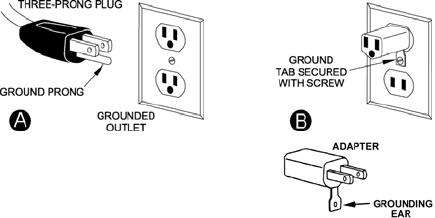
115 Volt Operation Only
Referring to Figure A:
As received from the factory, your table saw is
ready to run at 115-volt operation. This table
saw, when wired for 115 volt, is intended for use
on a circuit that has an outlet and a plug that
looks like the one illustrated in (A). A temporary
adapter, which looks like the adapter shown in
(B), may be used to connect this plug to a two-
pole receptacle if a properly grounded outlet is
not available. The temporary adapter should
only be used until a properly grounded outlet
can be installed by a qualified electrician. This
adapter is not applicable in Canada. The green
colored rigid ear, lug, or tab, extending from the
adapter, must be connected to a permanent
ground such as a properly grounded outlet box.
Figure A
Extension Cords
Make sure your extension cord is in good
condition. When using an extension cord, be
sure to use one heavy enough to carry the
current your machine will draw. An undersized
cord will cause a drop in the line voltage
resulting in power loss and overheating. The
table below shows the correct size to use
depending on the cord length and nameplate
ampere rating. If in doubt, use the next heavier
gauge. Remember, the smaller the gauge
number, the heavier the cord.
Cord Length AWG
00 – 25ft 016
225 – 50ft 014
Important: Make certain the receptacle in
question is properly grounded. If you are not
sure, have a registered electrician check the
receptacle.
9
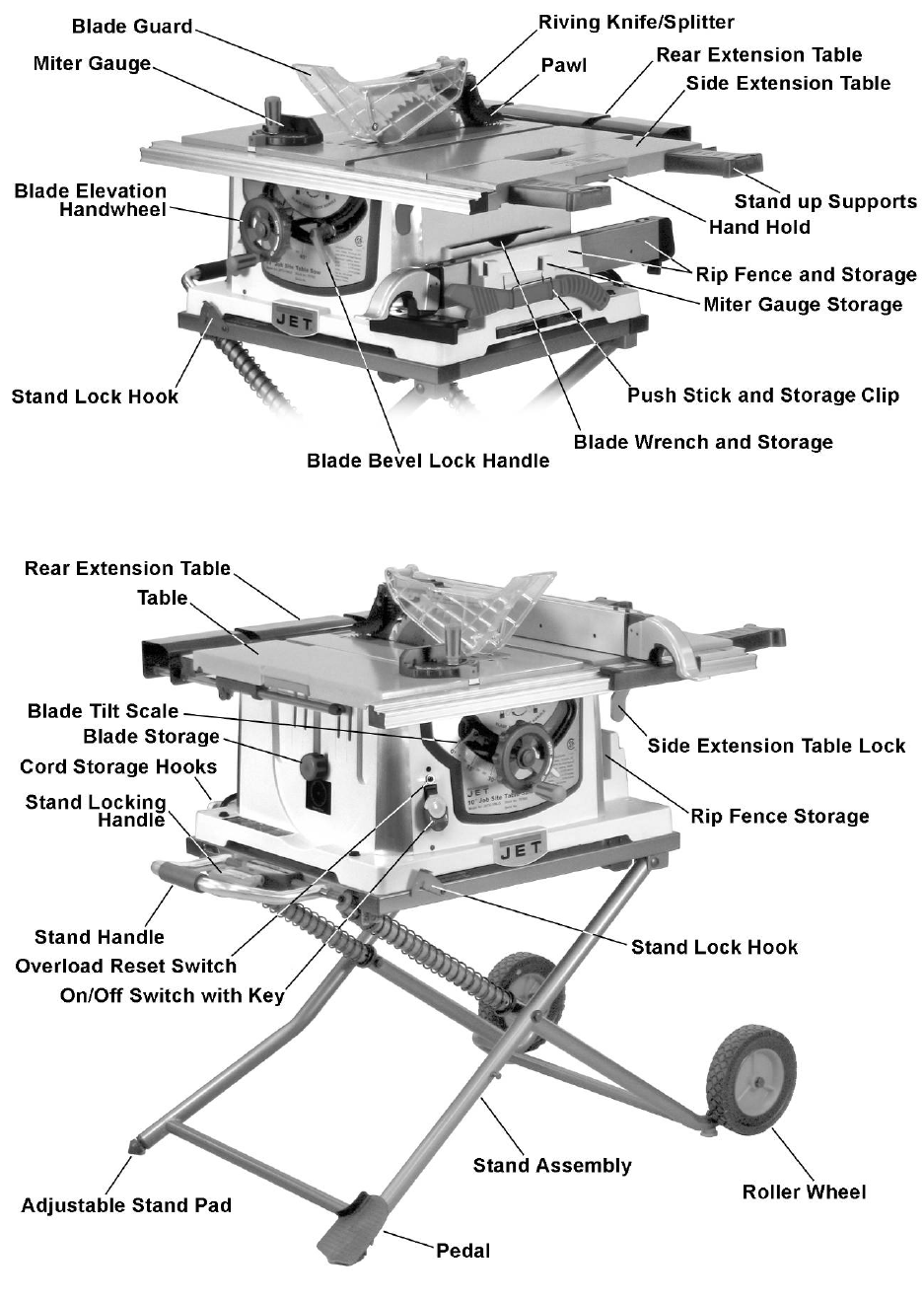
Features
Figure 1 – Features
10
Shipping Contents
Unpacking
1. Remove the contents from the shipping
container.
2. Compare the contents of the shipping
container and hardware bags with the lists
found below. Make certain that all items are
accounted for before discarding any packing
material. Report any shortages or damage
to your JET distributor.
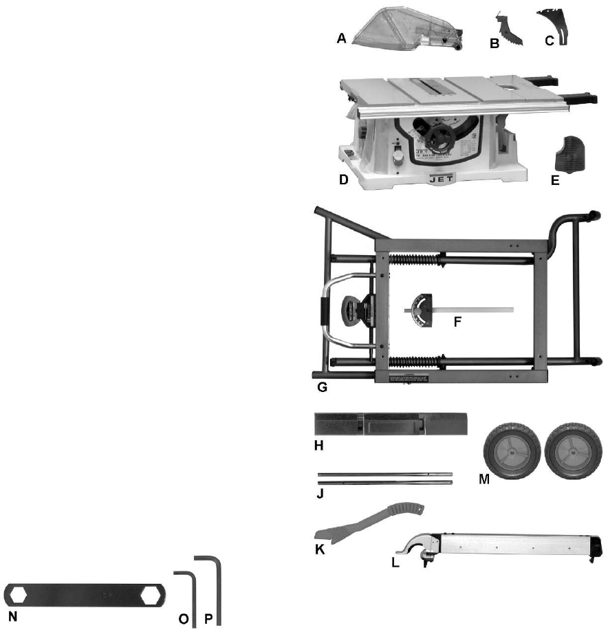
Contents of the Shipping Container
(These items shown in Figure 3)
A Blade Guard (1)
B Kickback Pawl (1)
C Riving Knife (1)
D Table Saw (1)
E Pedal (1)
F Miter Gauge (1)
G Stand Assembly (1)
H Rear Table Extension (1)
J Rear Table Extension Tube (2)
K Push Stick (1)
L Rip Fence (1)
M Roller Wheel (2)
-- Hardware Bags
see contents on next page
-- Owner’s Manual (1)
-- Warranty Registration Card
Tools Supplied for Assembly
(These items shown in Figure 2)
N Blade Wrench
O 4mm Hex Wrench
P 5mm Hex Wrench
Figure 2 – Supplied Tools
Tools not included
00Adjustable Wrench
006mm Hex Wrench
00Crosspoint Screwdriver
00Combination Wrench
Figure 3 – Contents of Shipping Container
11
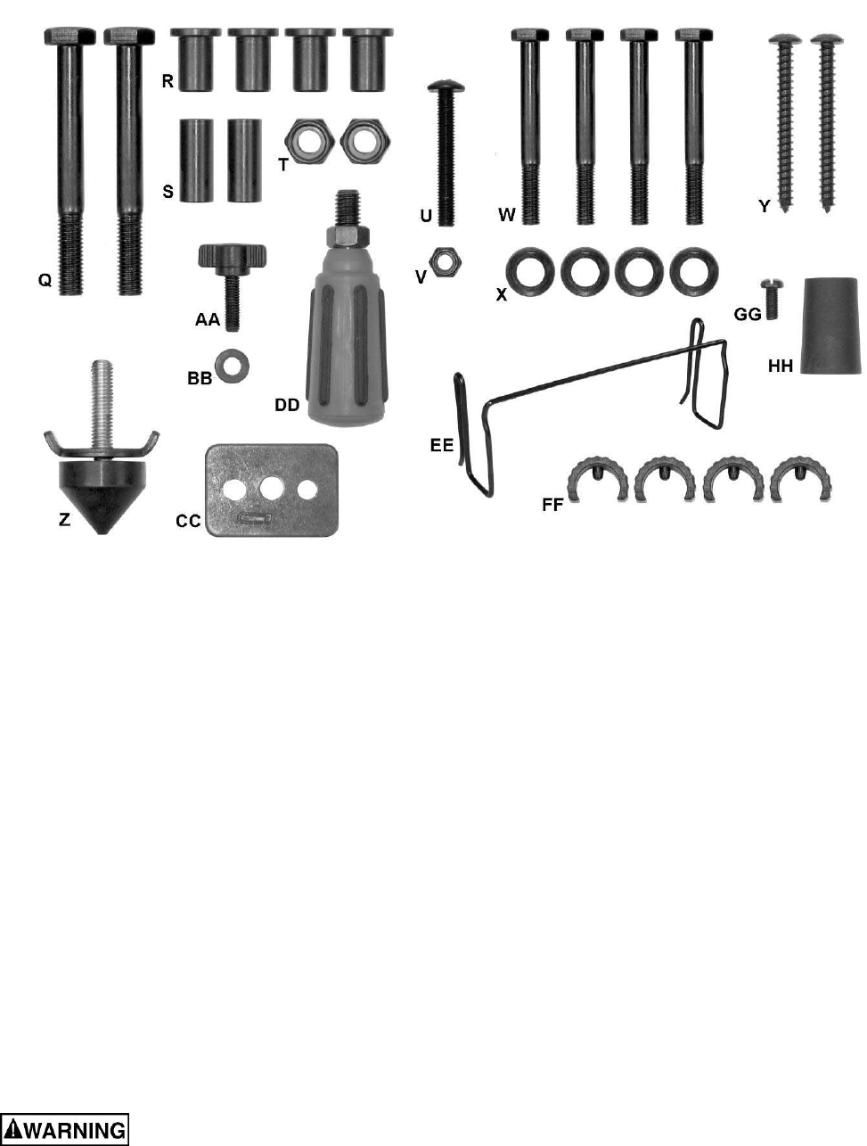
Figure 4 – Hardware
Hardware
The following items are shown in Figure 4.
Q Screw (2)
R Collar (4)
S Shaft Sleeve (2)
T Nut (2)
U Screw (1)
V Nut (1)
W Screw (4)
X Plastic Flat Washer (4)
Y Screw (2)
aZ oStand Pad (1)
AA oSplitter/Riving Knife Lock Knob (1)
BB oFlat Washer (1)
CC oSplitter/Riving Knife Plate (1)
DD oHandwheel Handle (1)
EE oPush Stick Storage Clip (1)
FF oPlastic Stop (4)
GG oScrew (1)
HH oRear Extension Pad (1)
Read and understand all assembly instructions before attempting assembly! Failure to
comply may cause serious injury!
12
Assembl
y
Note: The letter designators used in the assembly
section are the same as those used in the shipping
contents and hardware section (page 10-11) for the
purpose of simplifying part identification.
Stand
Stand may pop up unexpectedly
without weight of saw on stand. In order to
avoid injury, verify that the lock hook (G
1
, Fig.
7) located at the front of the stand is locked
onto the stop screw before mounting the table
saw.
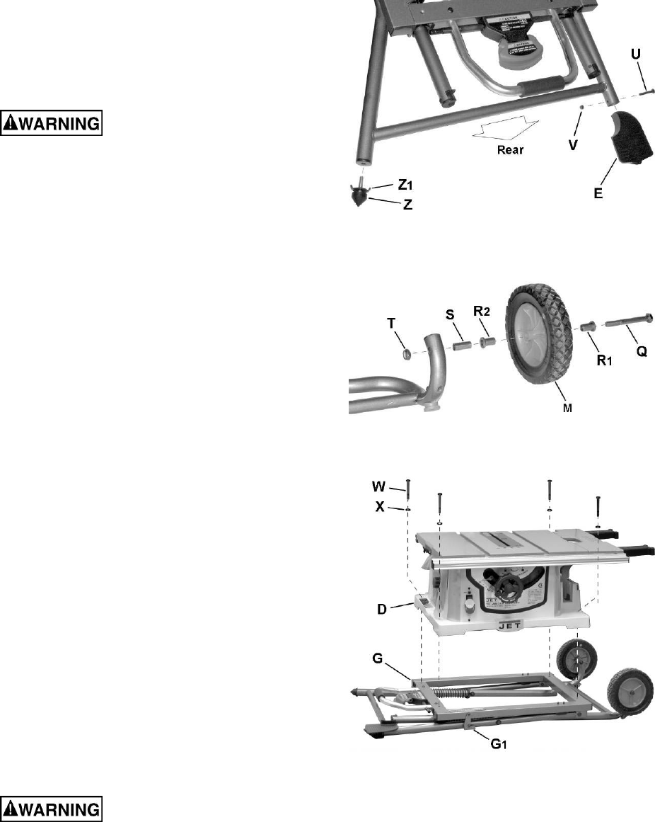
Stand Pad and Pedal
Referring to figure 5:
1. Thread the stand pad (Z) through the wing nut
(Z
1
) to the bottom of the left rear leg.
Adjustment is described in Setting up the Stand
on page 17.
2. Attach the pedal (E) to the left front leg using
the screw (U) and hex nut (V). Secure with
10mm socket and crosspoint screwdriver.
Wheel
Referring to Figure 6:
3. Attach two collars (R
1
, R
2
) to each roller wheel
(M).
4. Attach one roller wheel assembly to the right
front leg using the bolt (Q), the shaft sleeve (S),
and the hex nut (T) as shown.
Note: Verify that the side of the wheel that has
more ribs is facing toward the inside of the
stand.
5. Attach the other roller wheel to the right rear
leg using the same manner.
6. Tighten screw (Q) and hex nut (T) with two
17mm wrenches.
Note: Do not overtighten, because doing so will
not allow the wheels to turn.
Attaching Saw to Stand
Referring to Figure 7:
Do not cut the bands and
release the stand hook (G
1
) until the table saw
is properly attached to the stand.
1. Place table saw (D) on the top of stand (G)
aligning the holes in the base with the holes in
the stand.
Figure 5
Figure 6
Figure 7
2. Insert four hex bolts (W) through the plastic flat
washers (X) and holes in base and stand.
3. Tighten all four bolts (W) with a 13 mm socket,
but do not overtighten.
Note: To set up the stand or fold down the stand,
see Setting Up The Stand and Folding The Stand
on page 17.
13
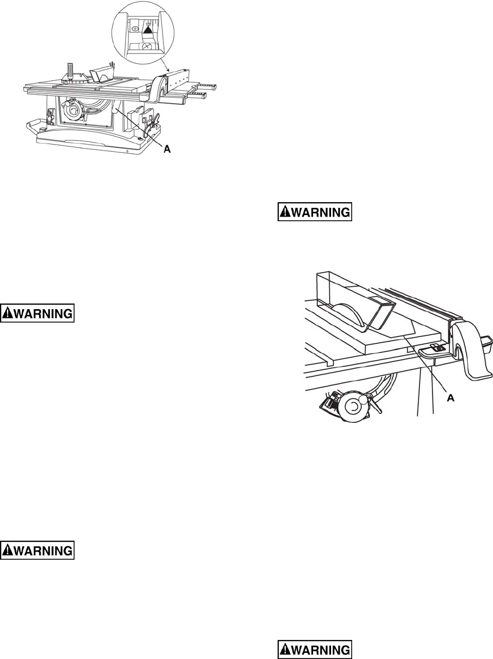
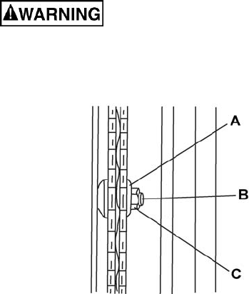
Mounting the Saw to Work Surface
A hole to allow sawdust to fall
through must be provided when the saw is
mounted to a work surface (stand not used).
Failure to do so will cause sawdust to build up
in the motor area, which can result in fire or
damage to the motor.
Referring to Figure 8:
If the stand is not used, the saw must be properly
secured to a sturdy workbench through the four
mounting holes that are located at the base of the
saw.
The surface of the table where the saw is to be
mounted must have a hole (B) that is large enough
to facilitate sawdust fall-through and removal.
1. Square the saw on the mounting surface, and
mark the location of the four 3/8 in. mounting
holes (A).
2. Drill pilot holes in two diagonal corners (marked
(A) in the mounting surface.
3. Mark an 11x11 in. square (B), centered bet-
ween the four mounting holes (A).
4. Cut out and remove the square.
5. This opening will allow sawdust to fall through
the saw base.
6. Place the saw on the work surface, and align
the mounting holes of the saw with the two
holes drilled in step 2.
7. Fasten the saw to the work surface using
screws (Y, Fig. 4) provided.
Do not operate this saw on the
floor. Doing so is very dangerous. Failure to
comply may cause serious injury!
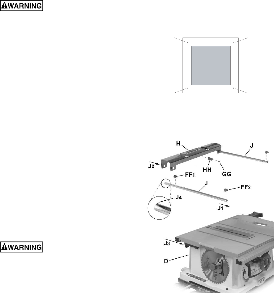
Rear Table Extension
Referring to Figure 9:
1. Attach the rubber pad (HH) to the inside of the
rear table extension (H). Thread the screw (GG)
thru the rubber pad with the screwdriver. Tighten
the screw (GG).
2. Insert the two rear table extension tubes (J) into
the rear table extension (H). Follow arrows J
1
, J
2
.
Note: The tubes (J) must be inserted into the
back of the extension with the bent end last so
that the bar will hold the extension in place.
(J
4
).
3. Snap plastic stops (FF
1
) over the extension
tubes (J). This will ‘lock’ the tube (J) into the
extension (H). Make sure the pin in the stops fit
A
A
A
A
B
Figure 8
Figure 9
into the matching holes in the extension tubes.
4. Following arrows J1, J3, insert the rear table
extension into the two extension tube brackets
(J
3
) under the table.
5. Snap two black plastic stops (FF
2
) over the end
of the rear table extension tubes (J). Make sure
the pin in the stops fit into the matching holes in
the extension tubes.
14
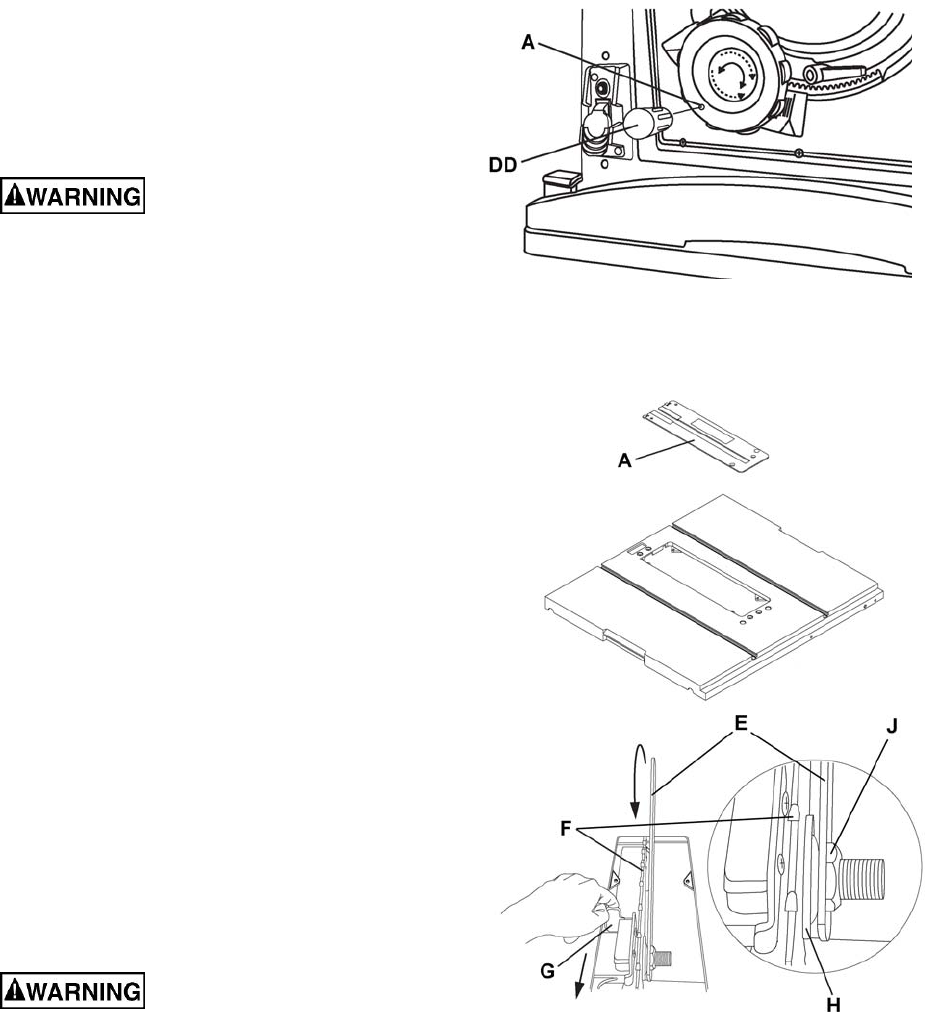
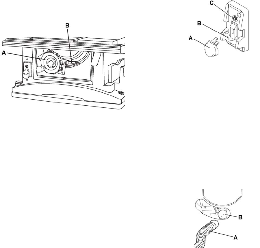
Handwheel Handle
Thread the handwheel handle (DD, Fig. 10) into the
handwheel hole (A. Fig. 10), and then tighten the
nut against the handwheel with a 10 mm wrench.
Installing the Blade
To avoid injury from an
accidental start, make sure the switch is in the
OFF position and the plug is disconnected from
the power source outlet.
Referring to Figure 11:
1. Remove the table insert (A).
2. Place the blade onto the arbor with the blade
teeth pointing forward to the front of the saw.
3. Make sure the blade fits flush against the inner
flange.
4. Clean the outer blade flange (H) and install it
onto the arbor and against the blade.
5. Thread the arbor nut onto the arbor, making
sure the flat side of the nut is against the blade,
then hand-tighten.
6. Pull the arbor locking lever (G) toward the front
of the machine while spinning the blade by
hand until the latch locks into place and the
blade will no longer turn.
7. Place the wrench (E) on the arbor nut and turn
clockwise (toward the rear of the saw table).
8. Lower the blade to the down position. Replace
the table insert (A) and the blade guard.
Important: Do not operate this saw until the blade
and blade guard splitter are aligned and in working
order.
Removing the Blade
To avoid injury from an
accidental start, make sure the switch is in the
OFF position and the plug is disconnected from
the power source outlet.
Referring To Figure 11:
1. Remove the table insert (A) and raise the blade
to the maximum height by turning the blade
elevation handwheel clockwise.
2. Remove blade guard.
3. Adjust the blade to the 90° vertical position by
unlocking the blade tilting lock knob and turning
the bevel tilting handwheel counterclockwise,
and then lock into position.
4. Pull the arbor locking lever (G) toward the front
Figure 10
Figure 11
of the tool while spinning the blade by hand
until the latch locks into place and the blade will
no longer turn.
5. Place the blade wrench (E) on the arbor nut (J).
6. Loosen and remove the arbor nut and the
flange by pulling the wrench towards the front
of the machine.
7. Then remove the blade (F). Clean but do not
remove the inner blade flange before
reassembling the blade.
15
Blade Guard Assembly
To avoid injury from an
accidental start, make sure the switch is in the
OFF position and the plug is disconnected from
the power source outlet.
● When installing the blade guard, cover the
blade teeth with a piece of folded cardboard to
protect yourself from possible injury.
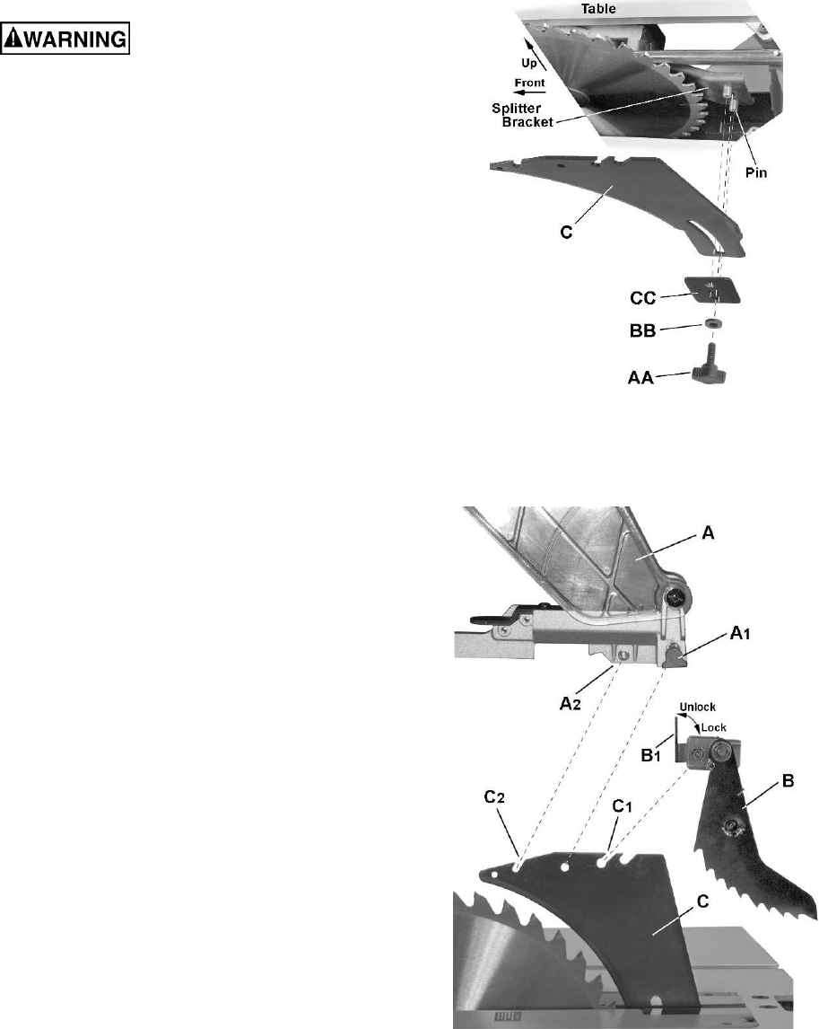
Splitter (riving knife) installation (Figure 12)
1. Remove the table insert.
2. Raise the blade arbor to the maximum height
and set the bevel angle to 0°.
3. Install the splitter (C) onto the splitter bracket,
fitting the curved slot on the splitter over the
bracket pins.
4. Install the splitter plate (CC), followed by the
flat washer (BB) and lock knob (AA). Tighten
the lock knob, leaving enough slack to
manually adjust the splitter (C).
5. Raise the splitter (C) as high as it will go, then
tighten the lock knob (AA) to secure the splitter
in this position.
Kickback pawl installation (Figure 12a)
6. Place the lock lever (B
1
) on the kickback pawl
assembly (B) in the unlock position.
7. Install the kickback pawl (B) onto the splitter.
The flat sides of the mounting pin on the
kickback pawls should pass though the
mounting slot (C1) on the splitter (C).
Note: Make sure the “anti-kick back pawls do
not get caught between the insert and the
guard, but rest on top of the insert.
8. Press firmly down on the kickback pawl to
ensure that it is properly seated on the splitter,
then place the lock lever (B1) in the lock
position.
Blade guard installation (Figure 12a)
9. Slide the lock lever (A1) on the blade guard (A) up
and hold..
10. Place the blade guard (A) on the splitter (C),
meshing the pin (A
2
) on the blade guard with the
slot (C
2
) on the splitter.
11. Push the blade guard assembly down firmly on the
splitter; then release the lock lever (A
1
).
12. Lift up on the blade guard assembly (A) to confirm
that it is firmly secured to the splitter (C).
Figure 12
Figure 12a
16
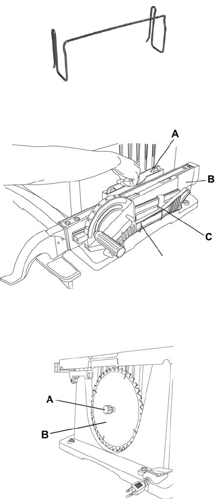
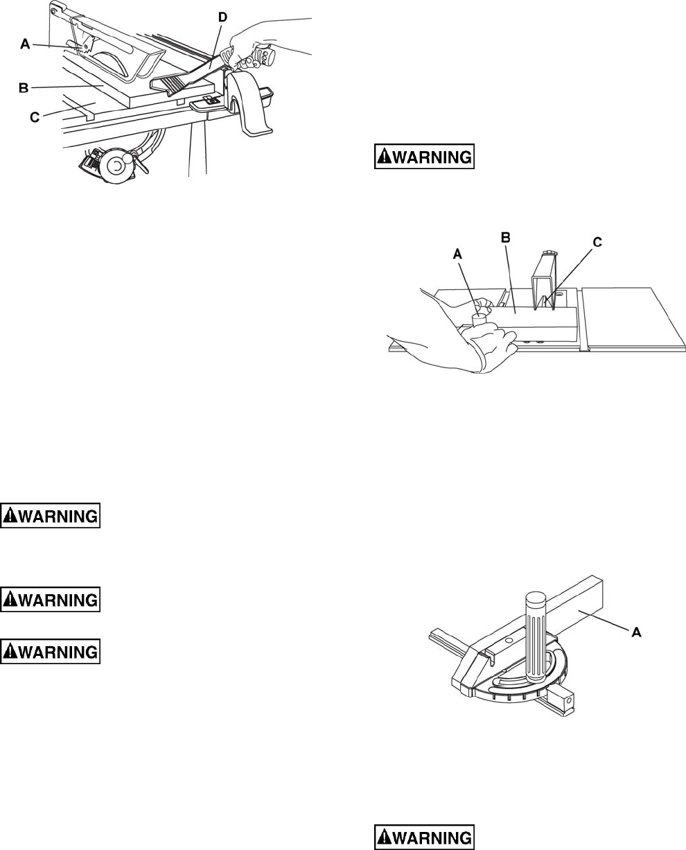
Installing the Push-stick Storage
Attach the metal push-stick storage bracket (Figure 13)
into the provided slot (D, Fig. 14) on the right side of the
body shell. The bracket will snap into place.
Storage
Rip fence and miter gauge
Storage brackets for the rip fence (B, Fig. 14) and
miter gauge (C, Fig. 14) are located on the right
side of the saw housing.
Note: Adjust the miter gauge to 45º-60º
before
putting away in storage.
Blade wrench
Insert the handle of the blade wrench (A, Fig. 14)
into the slot located to the right side of the saw
housing.
Blade
1. Loosen and remove the knob (A, Fig. 15) on
the left side of the saw housing.
2. Place extra blades (B, Fig. 15) onto the
bushing. Replace the knob and tighten.
Figure 13
Figure 14
Figure 15
D
17
Adjustments
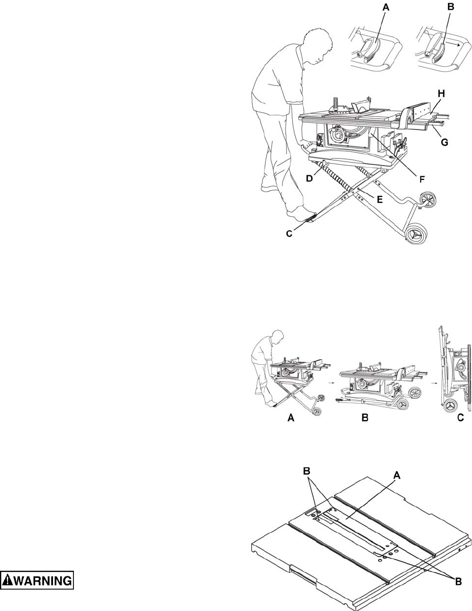
Setting up the Stand
Referring to Figure 16:
1. Release the stand lock hook (D) by sliding it
away from the stop screw.
2. Raise the handle cover (A) first, then pull the
locking handle (B) out and hold.
3. Step on the pedal (C) and pull the stand
upward until it is fully unfolded.
4. Release the locking handle (B) to lock the
stand into position. Lower the cover (A).
Note: Make sure the stand is locked securely.
5. Place the stand on a level surface and adjust
the left stand pad (Z, Fig. 5) so that all legs are
contacting the floor and are at a similar angle to
the floor.
Note: Make sure the table saw is locked
securely in position. Adjust the stand pad to
make sure the table saw is totally stable.
Folding the Stand
1. Raise the handle cover (A, Fig. 16) first and
pull the locking handle (B, Fig. 16) out.
2. Push slowly downward on the stand (A, B, Fig. 17).
3. Release the locking handle (B, Fig. 16).
4. Rotate the stand hook (D, Fig. 16) onto the
stop screw to secure the stand legs into the
collapsed position.
5. Secure the side extension table (H, Fig. 16) by
pushing the cam locking lever (F, Fig. 16)
downward.
Note: For convenient storage, there are two
stand up supports (G, Fig. 16) on the right side
of the table saw for supporting the table saw
when not in use (C, Fig. 17).
Adjusting the Table Insert
The table insert (A, Fig. 18) is already installed on
your table saw. Verify that the table insert is flush with
the table top surface on all four corners of the insert.
To avoid serious injury, the
table insert must be level with the table.
If the table insert is not flush with the table, adjust
the four hex screws (B, Fig. 18) with a 4 mm hex
wrench until it is flush with the table.
To raise the insert, turn the hex screws (B) counter-
Figure 16
Figure 17
Figure 18
clockwise. To lower the insert, turn the hex screws
clockwise.
18
Aligning the Blade Guard Splitter
To avoid injury from an
accidental start, make sure the switch is in the
OFF position and the plug is disconnected.
● When installing the blade guard, cover the
blade teeth with a piece of folded cardboard to
protect yourself from possible injury.
● Never operate this tool without the safety
guard in place for all through sawing operations.
Important: The splitter must always be correctly
aligned with the blade so the cut workpiece will
pass on either side without binding or twisting.
The splitter/riving knife is adjusted at the factory
and should not require adjustment. In the event that
adjustment becomes necessary, follow the
procedure below.
Referring to Figure 19:
1. Remove the table insert and raise the blade to
the maximum height by turning the blade
elevation handwheel clockwise.
2. Remove the blade guard and pawl assembly
(see Blade Guard Assembly on page 15)
3. Adjust the blade to the 90° vertical position by
unlocking the blade tilting lock knob and turning
the bevel tilting handwheel counterclockwise,
and then lock into position.
4. To see if the blade (A) and splitter (B) are
correctly aligned, lay a straightedge along the
side of the blade and against the splitter
(making sure the square is between the teeth
of the blade).
The blade and splitter should be perfectly in-line. If
the blade and splitter are not correctly aligned:
5. Loosen two screws (C) just enough to permit
adjustment of the splitter mounting bracket (D).
6. Adjust the splitter (B) until it is aligned with the
saw blade (A), using the straightedge as
reference.
7. Tighten screws (C) and recheck alignment.
8. Replace table insert, pawl assembly and blade
guard assembly.
Figure 19
19
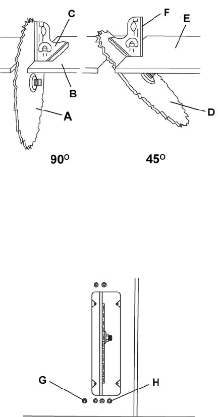
90° and 45° Positive Stop Adjustment
Adjusting the Positive Stop
Your saw has positive stops that will quickly
position the saw blade at 90° and 45° to the table.
Make adjustments only if necessary.
90° Stop
1. Disconnect the saw from the power source.
2. Raise the blade to the maximum elevation.
3. Loosen the blade bevel lock handle. Adjust the
blade (A) to the maximum vertical position and
retighten the bevel lock handle.
4. Place a combination square (C) on the table (B)
and against the blade (A) to determine if the
blade is 90° to the table.
5. If the blade is not 90° to the table, loosen or
tighten the hex screw (G) with a 5 mm hex
wrench until 90° is achieved.
6. Loosen the bevel lock handle and reset the
blade at the maximum vertical position, then
tighten the bevel lock handle.
7. Check again to see if the blade is 90° to the
table. If not, repeat step 5.
8. Check the bevel angle scale. If the pointer does
not read 0°, loosen the screw that secures the
pointer, adjust to read 0°, retighten the pointer
screw.
45° Stop
1. Disconnect the saw from the power source.
2. Raise the blade to the maximum elevation.
3. Loosen the blade bevel lock handle. Adjust the
blade (D) to the maximum bevel position (45°)
and retighten the bevel lock handle.
4. Place a combination square (F) on the table (E)
and against the blade (D) to determine if the
blade is 45° to the table.
5. If the blade is not 45° to the table, loosen or
tighten the hex screw (H) with a 5 mm hex
wrench until 45° is achieved.
6. Loosen the bevel lock handle and reset the
blade at the maximum bevel position (45°),
then tighten the bevel lock handle.
7. Check again to see if the blade is 45° to the
table. If not, repeat step 5.
Blade Tilt Pointer
When the blade is positioned at 90°, loosen the
holding screw, adjust the blade tilt pointer to read
0° on the scale, then retighten the screw.
Figure 20
Figure 21
20
Blade Parallel to the Miter Slot
To avoid injury from an
accidental start, make sure the switch is in the
OFF position and the plug is disconnected from
the power source outlet.
This adjustment was made at the factory, but it
should be rechecked and adjusted if necessary.
This adjustment must be correct to assure accurate
cuts and to prevent the possibility of kickback,
which can result in serious injury.
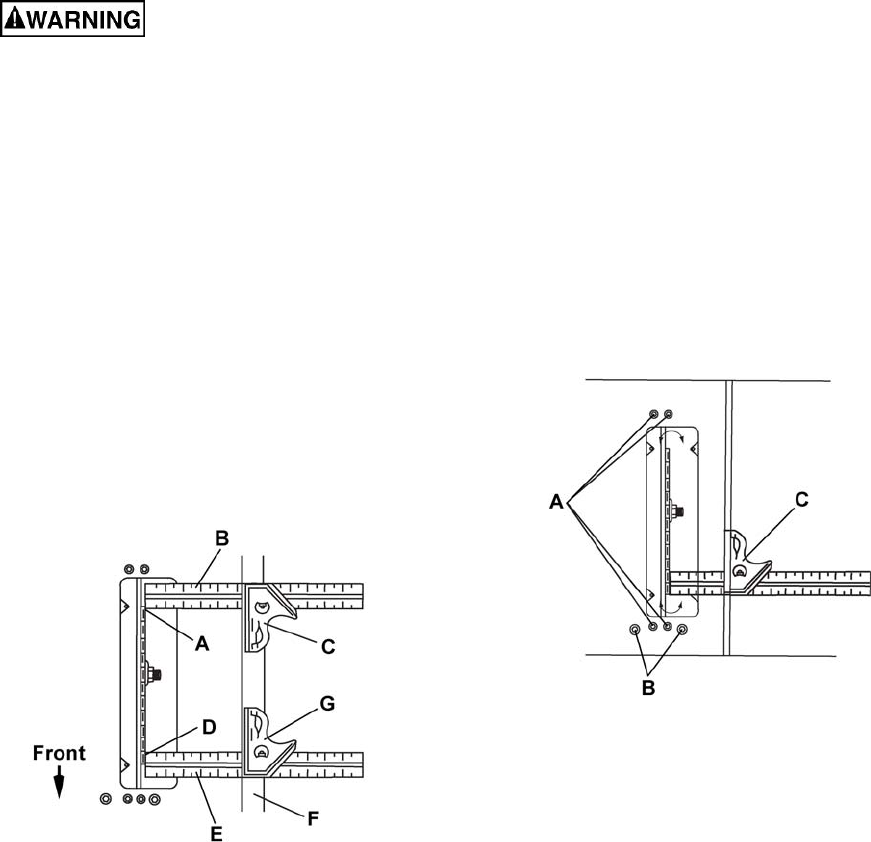
Referring to Figure 22:
1. Remove the yellow switch key and unplug the saw.
2. Remove the blade guard.
3. Raise the blade to the maximum height and set
the bevel angle at 0°
4. Select and mark with a felt tip marker, one
blade tooth with a “right set” angle and position
this tooth at the front of the saw approximately
1/2 in. above the table (D) .
Figure 22
5. Place the combination square base (G) into the
right side miter gauge slot (F) flush against the
inside of the miter gauge slot.
6. Adjust the ruler (E) so it touches the front
marked tooth (D) and lock ruler so it holds its
position in the square assembly.
7. Next rotate the blade, moving the marked tooth
(D) to its new position (A) at the rear of the
saw.
8. Carefully move the combination square from
position (G) to (C).
9. If the ruler touches the marked tooth at the
front and rear position (E at D, B at A), no
adjustment is needed. If not, perform the
adjustment procedure described in the next
section.
Additional Blade Adjustments
Refer to Figure 23.
If the front and rear measurements are not the
same:
1. Remove the combination square (C) and
loosen the four adjusting screws (A) on the top
of the table about a half turn.
2. Cover the blade with a folded piece of
cardboard to protect your hands. Move the
blade and motor mounting rod carefully to the
left or right as much as needed to align the
blade correctly.
3. Tighten the four screws (A) and remeasure, as
described in steps 4 to 9 in the previous section.
Figure 23
4. If sufficient adjustment cannot be made by the
four adjusting screws (A), then also loosen the
two adjusting screws (B) and repeat all
previous steps. Loosen these screws (B) only if
necessary as they are set for accurate 90° and
45° settings.
5. Recheck the blade clearance making sure that
the blade does not hit the table insert or other
parts when at the 90° and 45° settings.
6. Retighten all four adjusting screws (A) and
reset the 90° and 45° setting as described in
the 90° and 45° Positive Stop Adjustment
section (page 19).
21
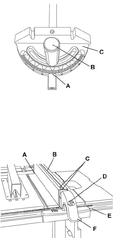
Adjusting the Miter Gauge
Referring to Figure 24:
1. Loosen the lock handle (B) to allow the miter
body (C) to rotate freely. Position the miter
body at 90° so the positive detent secures its
position. Tighten the lock handle (B) to hold the
miter body in position.
2. If the pointer (A) requires adjustment, loosen
the screw under the pointer with a screwdriver.
Adjust the pointer to 90° on the scale, then
firmly tighten the adjustment screw.
To change angles on the miter gauge:
3. Loosen the lock handle (B) and rotate the miter
body to the desired angle as indicated by the
scale. Secure in position by tightening the lock
handle.
Rip Fence Adjustment
Referring to Figure 25:
1. For adjustments, position the fence to the right
of the blade, parallel with the miter gauge slot.
2. Place the rear clamp (A) of the fence on the
back rail of the table, and lower the front end
over the front rail (E). Push the handle (F)
down to lock.
3. To change the position of the fence, lift up on
the handle to unlock, and slide the fence to the
desired position, then push the handle down to
lock.
4. To check the rip fence adjustment, place the
fence along one edge of the miter gauge
groove, and lock the handle. It should be
parallel to the miter groove to provide accurate
cuts.
If an adjustment is needed to make it parallel:
1. Loosen the two hex bolts (C) on the top of the
rip fence, and lift up on the handle (F).
2. Adjust the fence (B) so it is parallel to the miter
gauge slot and lock the handle (F) into position.
3. Make sure the fence (B) is parallel to the slot
and tighten the two hex bolts (C) securely.
4. Unlock the fence handle (F) and slide the fence
left and right, then reposition it against the miter
gauge slot again and lock into position to
double check its alignment.
Failure to properly align the fence can cause
“kickback” and serious injury could occur.
Figure 24
Figure 25
If the fence is loose when the handle is in the
locked position:
1. Move the handle upward to the unlocked
position.
2. Turn the adjusting screw (D) clockwise until the
rear clamp is snug.
3. Do not turn the adjusting screw more than 1/4
turn at a time.
4. Over-tightening the screw will cause the rip
fence to come out of alignment.
22
Rip Fence Indicator
The rip fence indicator points to the scale on the
front of the table saw. The measurement shown by
the indicator will provide the user with accuracy up
to 1/16 of an inch. The measurement shown is the
distance from the blade to the side of the fence
closest to the blade.
To check the accuracy:
1. Measure the actual distance to the side of the
rip fence.
If there is a difference between the measurement
and the indicator, adjust the indicator as follows:
2. Loosen the indicator screw (A, Fig. 26).
3. Slide the indicator to the correct measurement
position on the scale, then retighten the screw.
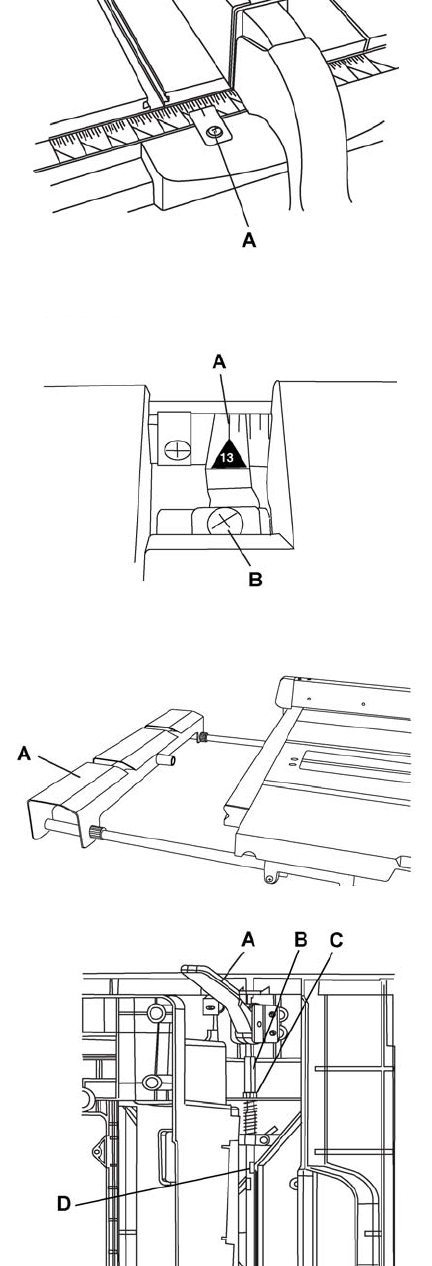
Table Extension Scale Pointer
The table extension scale pointer (A, Fig. 27)
should be at 13 inches on the scale when the
extension is in the closed position. If adjustment is
required, loosen the holding screw (B, Fig. 27),
position the pointer over the 13 inch marker and re-
tighten the screw.
Rear Table Extension Adjustment
The rear table extension (A, Fig. 28) should be
positioned as close as possible to the rear of the
table when ripping short material.
The rear table extension should be fully extended
when ripping longer materials that require extra
support.
Adjusting the Locking Lever
If the extension table moves when it is open and
locked in place, the cam locking lever (A, Fig. 29)
may be loose and require adjustment.
To adjust the locking lever tension:
1. Hold the stud (B) stationary, and loosen the nut
(C) with a 10 mm wrench.
2. Rotate the rod using a wrench on one of the
flats (D). Do not overtension!
3. Re-tighten the nut (C).
Figure 26
Figure 27
Figure 28
Figure 29
23
Operation
Basic Saw Operations
Raising the Blade
To raise or lower the blade, turn the blade elevation
handwheel (A, Fig. 30) to the desired blade height,
and then tighten the bevel lock handle (B, Fig. 30) to
maintain the desired blade angle.
Figure 30
Tilting the Blade
Two methods are available for tilting the saw blade.
Rapid blade tilting:
Loosen the bevel lock handle (B, Fig. 30), move the
handwheel (A, Fig. 30) to the desired angle, then
tighten the bevel lock handle.
Fine adjustment blade tilting:
Loosen the bevel lock handle (B, Fig. 30), push in
the handwheel (A, Fig. 30) and at the same time turn
the handwheel (A, Fig. 30) to tilt the saw blade.
When the saw blade is at the desired angle, tighten
the bevel lock handle (B, Fig. 30).
On/Off Switch
The ON / OFF switch has a removable safety key.
With the key removed from the switch, unauthorized
and hazardous use by children and others is
minimized.
Referring to Figure 31:
1. To turn the saw ON, insert the safety switch key
(A) into the slot in the switch (B). Move the
switch upward to the ON position.
2. To turn the saw OFF, move the switch
downward.
3. To lock the switch in the OFF position, grasp the
end (or yellow part) of the safety switch key (A),
and pull it out.
4. With the removable safety key removed, the
switch will not operate.
5. If the removable safety key is removed while the
saw is running, it can be turned OFF but cannot
be restarted without inserting the removable
safety key (A).
Figure 31
Overload Protection
This saw has an overload reset button (C, Fig. 31)
that resets the motor after it shuts off due to
overloading or low voltage. If the motor stops during
operation, turn the ON / OFF switch to the OFF
position. Wait about five minutes for the motor to
cool, the push the reset button (C, Fig. 31) and turn
the switch to the ON position.
Dust Chute
To prevent fire hazard, clean and remove
sawdust from under the saw frequently.
To prevent sawdust buildup inside the saw housing,
attach a vacuum hose (A, Fig. 32) to the dust chute
(B, Fig. 32) at the rear of the table saw. DO NOT
operate the saw with the hose in place unless the
vacuum is turned on.
Figure 32
Using the Table Extension
Use the scale on the front rail for rip cuts up to 13 in.
For rip cuts greater than 13 in., set and the lock the
fence on the 13 in. mark. Unlock the extension table,
and slide the table with the fence to the desired
dimension using the scale on the rear rail.
Referring to Figure 33:
1. Release the cam locking lever (A).
2. Slide the table extension to the desired
measurement and then tighten the cam locking
lever.
24
Figure 33
Cutting Operations
There are two basic types of cuts: ripping and
crosscutting. Ripping is cutting along the length and
the grain of the workpiece. Crosscutting is cutting
either across the width or across the grain of the
workpiece. (It is not safe to rip or crosscut by
freehand). Ripping requires the use of the rip fence,
and crosscutting requires the miter gauge. NEVER
USE THE TWO AT THE SAME TIME.
Before using the saw each time,
check the following:
• The blade is tightened to the arbor.
• The bevel angle lock knob is tightened.
• If ripping, make sure the fence is locked into
position and is parallel to the miter gauge
slot.
• The blade guard is in place and working
properly.
• Safety glasses are worn.
• The failure to adhere to these common safety
rules, and those printed in the front of this
manual, can greatly increase the likelihood
of injury.
Ripping
To prevent serious injury:
• Never use a miter gauge when ripping.
• Never use more than one rip fence during a
single cut.
• Do not allow familiarity or frequent use of
your table saw to cause careless mistakes.
Remember that even a careless fraction of a
second is enough to cause a severe injury.
• Keep both hands away from the blade and
clear from the path of the blade.
• The workpiece must have a straight edge
against the fence and must not be warped,
twisted, or bowed when ripping.
1. Remove the miter gauge and store it in the
“storage” compartment in the base of the saw.
2. Secure the rip fence to the table.
3. Raise the blade so it is about 1/8 in. higher than
the top of the workpiece.
4. Place the workpiece flat on the table and against
the fence. Keep the workpiece away from the
blade.
5. Turn the saw ON and wait for the blade to come
to full speed.
6. Slowly feed the workpiece into the blade by
pushing forward only on the workpiece section
(A, Fig. 34) that will pass between the blade and
the fence.
AVOID KICKBACK by pushing
forward on the section of the workpiece that
passes between the blade and the fence. Never
perform any freehand operations.
Figure 34
Referring to Figure 35:
7. Keep your thumbs off the table top. When both of
your thumbs touch the front edge of the table (C),
finish the cut with a push stick. To make an
additional push stick, use the pattern on page 29.
8. The push stick (D) should always be used for
any ripping operation.
9. Continue pushing the workpiece with the push
stick (D) until it passes through the blade guard
and clears the rear of the table.
10. Never pull the piece back when the blade is
turning. Turn the switch OFF. When the blade
completely stops, you can then remove the
workpiece.
Never attempt to pull the
workpiece backwards during a cutting operation.
This will cause kickback and serious injury to
the user can occur. When the blade completely
25
stops, raise the anti-kickback pawls (A) on each
side of the splitter and slide the workpiece out.
Figure 35
Bevel Ripping
This cut is the same as ripping except the blade
bevel angle is set to an angle other than “0º.
Ripping Small Pieces
To avoid injury from blade contact, never make cuts
narrower than 1/2 in. wide.
1. It is unsafe to rip small pieces. Instead, rip a
larger piece to obtain the size of the desired
piece.
2. When a small width is to be ripped and your
hand cannot safely pass between the blade and
the rip fence, use one or more push sticks to
move the workpiece. Always use a push stick
during ripping operations.
Crosscutting
Do not allow familiarity or
frequent use of your table saw to cause careless
mistakes. Remember that even a careless fraction
of a second is enough to cause a severe injury.
Keep both hands away from the
blade and the path of the blade.
Never attempt to pull the
workpiece backwards during a cutting operation.
This will cause kickback and serious injury to the
user can occur.
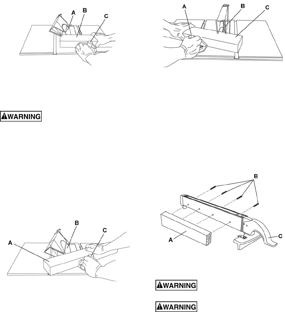
Referring to Figure 36:
1. Remove the rip fence and place the miter gauge
in the miter gauge slot on the table.
2. Adjust the blade height so that it is 1/8 in. higher
than the top of the workpiece.
3. Hold the workpiece firmly against the miter
gauge with the blade path in line with the
desired cut location.
4. Start the saw and wait for the blade (C) to come
up to full speed. Never stand directly in line of
the saw blade path, always stand to the side of
the blade that you are cutting on.
5. Keep the workpiece (B) against the face of the
miter gauge (A) and flat against the table. Then
slowly push the workpiece through the blade.
6. Do not try to pull the workpiece back with the
blade turning. Turn the switch OFF, and
carefully slide the workpiece out when the blade
has completely stopped.
Always position the larger surface
of the work-piece on the table when crosscutting
and/or bevel crosscutting to avoid instability.
Figure 36
Using Wood Facing on the Miter Gauge
Slots are provided in the miter gauge for attaching
an auxiliary facing (A) to make it easier to cut very
long or short pieces. Select a suitable piece of
straight wood, drill two holes through it and attach it
to the miter gauge with screws. Make sure the facing
does not interfere with the proper operation of the
sawblade guard. When cutting long workpieces, you
can make a simple outfeed support by clamping a
piece of plywood to a sawhorse.
Figure 37
Bevel Crosscutting 0°~45° Blade Level & 90° Miter
Ang le
This cutting operation is the same as crosscutting
except the blade is at a bevel angle other than 0°.
Always work to the right side of
the blade during this type of cut. The miter
gauge must be in the right side slot because the
bevel angle may cause the blade guard to
26
interfere with the cut if used on the left side
groove.
Referring to Figure 38:
1. Adjust the blade (A) to the desired angle, and
tighten the blade bevel lock knob.
2. Tighten the miter lock handle (C) at 90°.
3. Hold workpiece (B) firmly against the face of the
miter gauge throughout the cutting operation.
Figure 38
Compound Miter Crosscutting 0°~45° Blade Bevel
& 0°~45 Miter Angle
This sawing operation combines a miter angle with a
bevel angle.
Always work to the right side of
the blade during this type of cut. The miter
gauge must be in the right side groove because
the bevel angle may cause the blade guard to
interfere with the cut if used on the left side
groove.
1. Set the miter gauge (C) to the desired angle.
2. Place the miter gauge in the right side groove of
the table.
3. Set the blade (B) bevel to the desired bevel
angle and tighten the blade bevel lock knob.
4. Hold workpiece (A) firmly against the face of the
miter gauge throughout the cutting operation.
Figure 39
Mitering 0°~45° Miter Angle
This sawing operation is the same as crosscutting
except the miter gauge is locked at an angle other
than 90°.
1. Set the blade (B) to 0° bevel angle and tighten
the blade bevel lock knob.
2. Set the miter gauge (A) at the desired miter
angle and lock in position by tightening the miter
gauge locking handle.
3. Hold the workpiece (C) firmly against the face of
the miter gauge throughout the cutting
operation.
Figure 40
Using the Wood Facing on the Rip Fence
When performing some special cutting operations,
you can add a wood facing to either side of the rip
fence (C, Fig. 41).
1. Use a smooth straight 3/4 in. thick wood board
(A, Fig. 41) that is as long as the rip fence.
2. Attach the wood facing to the fence with wood
screws (B, Fig. 41) (not included) through the
holes in the fence. A wood fence should be used
when ripping material such as thin paneling to
prevent the material from catching between the
bottom of the fence and the table.
Figure 41
Dado Cuts
The maximum dado cut width is 13/16 in.
Only Stackable dado blades can
be used on this saw.
DO NOT use Adjustable or Wobble
type dadoes.
Referring to Figure 42:
27
1. Remove the saw blade and the blade guard for
dado cuts ONLY. Reinstall and realign blade
guard for all through- sawing operations. Install
a dado not exceeding 6 in. diameter and 13/16
in. width.
2. Install a dado table insert making sure that the
rear of the insert is flush with the table.
Note: A dado table insert is not included but can
be ordered (SN 707001) by calling the number
on the cover of this manual.
3. Instructions for operating the dado is packed
with the separately purchased dado set.
4. The arbor (B) on this saw restricts the maximum
width of the cut to 13/16 in.
5. It is not necessary to install the outside flange (A)
before threading on the arbor nut (C) for the
maximum 13/16 in. dado cuts. Make sure that the
arbor nut (C) is tight, and that at least one thread
of the arbor sticks out past the nut.
6. Use only the correct number of round outside
blades and inside chippers as shown in the dado
set’s instruction manual. Blade/chippers must
not exceed 13/16 in. total in width.
7. Check the saw to ensure that the dado will not
strike the housing, insert, or motor when in
operation.
For your own safety, always
replace the blade, blade guard assembly, and
table insert when you are finished with the dado
operation.
Figure 42
28
Maintenance
General Maintenance
For your own safety, turn the
switch OFF and remove the switch key. Remove
the plug from the power source outlet before
maintaining or lubricating your saw.
1. Clean out all sawdust that has accumulated
inside the saw cabinet and the motor.
2. Polish the saw table with an automotive wax to
keep it clean and to make it easier to slide the
workpiece.
3. Clean cutting blades with pitch and gum
remover.
4. A worn, cut, or damaged power cord should be
replaced immediately.
All electrical or mechanical
repairs should be attempted only by a trained
repair technician. Contact customer service for
assistance. Use only identical replacement parts.
Any other parts may create a hazard.
5. Use liquid dishwashing detergent and water to
clean all plastic parts.
Note: Certain cleaning chemicals can damage
plastic parts.
6. Avoid use of cleaning chemicals or solvents,
ammonia and household detergents containing
ammonia.
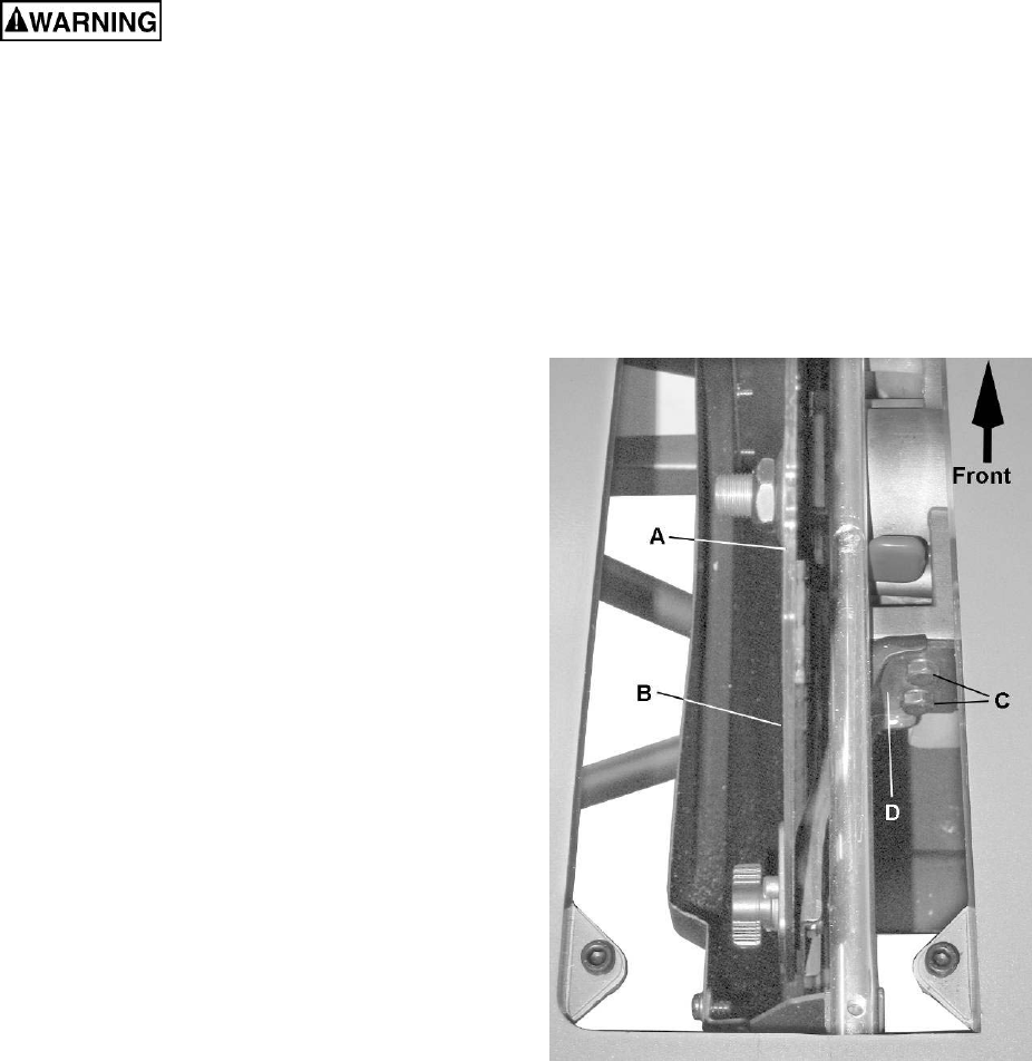
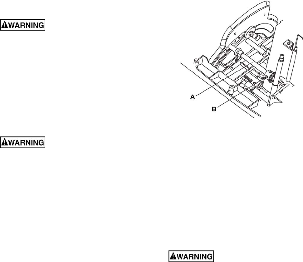
Blade Raising and Tilting Mechanism
After every five hours of operation, the blade raising
mechanism and tilting mechanism should be checked
for looseness, binding, or any other abnormalities.
Referring Figure 43:
1. With the saw disconnected from the power
source, turn the saw upside down and pull up
and push down on the motor unit.
2. Observe any movement of the motor mounting
mechanism. Looseness or play in the blade raising
screw rod (A) should be limited to 1/8” or less.
3. If excessive looseness is observed in any other
parts of the blade raising mechanism or tilting
mechanism, take the complete unit to a Service
Center.
Place a small amount of dry lubricant on the bevel
gear (B). The screw rod (A) must be kept clean and
free of sawdust, gum, pitch, and other contaminants
for smooth operations.
Figure 43
If excessive looseness is observed in any part of the
blade raising mechanism or tilting mechanism, take
the complete unit to a Service Center.
Lubrication
All motor bearings are permanently lubricated at the
factory and require no additional lubrication.
On all mechanical parts of your table saw where a
pivot or threaded rod is present, lubricate using
graphite or silicone. These dry lubricants will not
hold sawdust as would oil or grease.
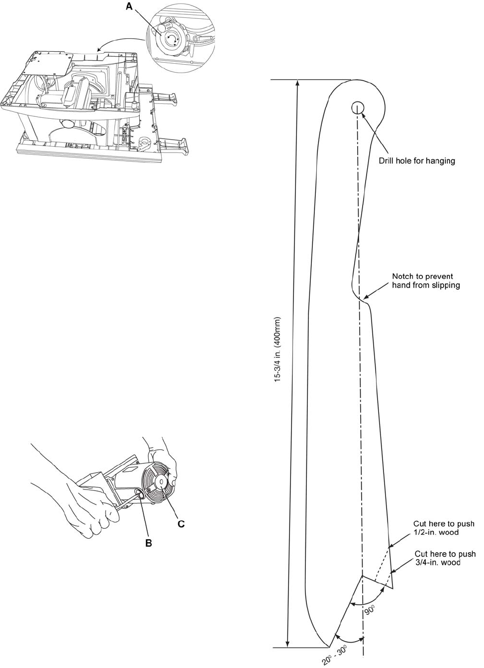
Replacing the Carbon Brushes
Always disconnect the plug from
the power source before inspecting the brushes.
The carbon brushes included with the unit will last
approximately 50 hours of running time, or 10,000 ON/
OFF cycles. Replace both carbon brushes when either
has less than 1/4 in. length of carbon remaining, or if
the spring or wire is damaged or burned.
1. Remove the blade guard, blade, rip fence, miter
gauge and stand assembly from the table saw.
2. Place cardboard or an old blanket on the floor to
protect the saw table surface.
3. Place the saw upside down on the protective
material.
4. Tilt the blade elevation/tilting handwheel (A, Fig. 44)
to the 45° position.
29
Figure 44
5. Referring to Figure 45:
6. Remove the black plastic cap (B) from the side
of the motor (C).
7. Carefully remove the spring-loaded cap, and
then pull out the brush and replace.
8. Replace the other side.
9. The ears on the metal end of the assembly go in
the same hole the carbon part fits into. Do not
overtighten the plastic cap.
10. Carefully set the saw in an upright position on a
clean level surface.
11. Replace the blade guard, blade, rip fence, miter
gauge and stand assembly to the table saw.
Note: To reinstall the same brushes, first make sure
the brushes go back in the way they came out. This
will avoid a break-in period that reduces motor
performance and increases wear.
Figure 45
Lubrication
All motor bearings are permanently lubricated at the
factory and require no additional lubrication.
On all mechanical parts of your table saw where a
pivot or threaded rod is present, lubricate using
graphite or silicone. These dry lubricants will not hold
sawdust as would oil or grease.
Push Stick Construction
Use solid wood or good quality plywood to construct
a push stick using the template below. The push
stick must be thinner than the width of the material
being cut.
Figure 46

Troubleshooting
Trouble Probable Cause Remedy
Saw will not start.
1. Saw is not plu
gg
ed in.
2. Fuse blown or circuit breaker
tripped.
3. Cord is damaged.
4. Debris in on/off switch
1. Plu
g
in saw.
2. Replace fuse or reset circuit breaker.
3. Replace power cord.
4. Remove switch from saw and
separate in half. Clean any debris
accumulated within.
Does not make
accurate 45° and
90° rip cuts.
1. Positive stop not ad
j
usted
correctly.
2. Tilt angle pointer not set
accurately.
1. Check blade with square and ad
j
ust
positive stop.
2. Check blade with square and adjust
to zero.
Material pinched
blade when ripping.
1. Rip fence not ali
g
ned with blade.
2. Warped wood, edge against fence
is not straight.
1. Check and ad
j
ust rip fence.
2. Select another piece of wood.
Material binds on
splitter. 1. Splitter not ali
g
ned correctl
y
with
blade. 1. Check and ali
g
n splitter with blade.
Saw makes
unsatisfactory cuts.
1. Dull blade.
2. Blade mounted backwards.
3. Gum or pitch on blade.
4. Incorrect blade for work being
done.
5. Gum or pitch on blade causing
erratic feed.
1. Replace blade.
2. Turn the blade around.
3. Remove blade and clean with
turpentine and coarse steel wool.
4. Change the blade.
5. Clean or change blade.
Material kicked
back
from blade.
1. Rip fence out of ad
j
ustment.
2. Splitter not aligned with blade.
3. Feeding stock without rip fence.
4. Splitter not in place.
5. Dull blade.
6. The operator letting go of material
before it is past saw blade.
7. Miter angle lock knob is not tight.
1.
A
li
g
n rip fence with miter
g
au
g
e slot.
2. Align splitter with blade.
3. Install and use rip fence.
4. Install and use splitter. (with guard)
5. Replace blade.
6. Push material all the way past saw
blade before releasing work.
7. Tighten knob.
Blade does not
raise or tilt freely. 1. Sawdust and dirt in elevation/tiltin
g
mechanisms. 1. Brush or blow out loose dust and dirt.
Blade does not
come up to speed.
Reset trips too
easily.
1. Extension cord too li
g
ht or to
o
long.
2. Low house voltage.
1. Replace with adequate size cord.
2. Contact your electric company.
Machine vibrates
excessively.
1. Saw not mounted securel
y
to
workbench.
2. Bench on uneven floor.
3. Damaged saw blade.
1. Ti
g
hten all mountin
g
hardware.
2. Reposition on flat level surface.
3. Replace blade.
Does not make
accurate 45° and
90° crosscuts.
1. Miter
g
au
g
e out of ad
j
ustment. 1.
A
d
j
ust miter
g
au
g
e.
A
nti-kickback pawls
catch on the table
insert opening.
1. Splitter/rivin
g
knife not set in full
raised position. 1. Set splitter/rivin
g
knife to full raised
position using the blade elevation
handwheel.
30
31
Parts
Ordering Replacement Parts
To order parts or reach our service department, call 1-800-274-6848, Monday through Friday (see our website for
business hours). Having the Model Number and Serial Number of your machine available when you call will allow
us to serve you quickly and accurately.
Table Saw
Note: Parts without part numbers are for reference only and cannot be purchased individually.
Index No. Part No. Description Size Qty
1 .............. JBTS10MJS-1 .........Bushing .............................................................................................. 1
2 .............. JBTS10MJS-2 .........Cable Clamp ...................................................................................... 1
3 .............. JBTS10MJS-3 .........Slide Plate.......................................................................................... 2
4 .............. ...............................Cus hio n Block .................................................................................... 4
5 .............. JBTS10MJS-5 .........Cord Cla mp ........................................................................................ 1
6 .............. JBTS10MJS-6 .........Bracket .............................................................................................. 1
7 .............. JBTS10MJS-7 .........Spacer ............................................................................................... 1
8 .............. JBTS10MJS-8 .........Bracket .............................................................................................. 1
9 .............. JBTS10MJS-9 .........Dust Housing Cover ............................................................................ 1
10 ............ JBTS10MJS-10 .......Strap.................................................................................................. 3
11 ............ JBTS10MJS-11 .......Washer .............................................................................................. 2
12 ............ JBTS10MJS-12 .......Push Stick Holder ............................................................................... 1
13 ............ JBTS10MJS-13 .......Wrench .............................................................................................. 1
14 ............ JBTS10MJS-14 .......Compression Spring ........................................................................... 1
15 ............ ...............................Compression Spring ........................................................................... 1
16 ............ ...............................Pin ..................................................................................................... 1
17 ............ ...............................Screw ................................................................................................ 1
18 ............ JBTS10MJS-18 .......Warning Label .................................................................................... 1
19 ............ JBTS10MJS-19 .......Bevel Gear ......................................................................................... 1
20 ............ JBTS10MJS-20 .......Bushing.............................................................................................. 3
21 ............ JBTS10MJS-21 .......Strap.................................................................................................. 1
22 ............ JBTS10MJS-22 .......Strap.................................................................................................. 4
23 ............ JBTS10MJS-23 .......Collar ................................................................................................. 1
24 ............ JBTS10MJS-24 .......Collar ................................................................................................. 1
25 ............ JBTS10MJS-25 .......Arbor Nut ........................................................................................... 1
26 ............ JBTS10MJS-26 .......Arbor Collar ........................................................................................ 1
27 ............ JBTS10MJS-27 .......Stop ................................................................................................... 4
28 ............ JBTS10MJS-28 .......Slide Base, Left .................................................................................. 1
29 ............ JBTS10MJS-29 .......Foam Strip ......................................................................................... 2
30 ............ JBTS10MJS-30 .......Bevel Gear ......................................................................................... 1
31 ............ TS-152705 ..............Hex Wrench .....................................................M4 ............................. 1
32 ............ TS-152706 ..............Hex Wrench .....................................................M5 ............................. 1
33 ............ TS-1550031 ............Flat Washer......................................................M5 ............................. 4
34 ............ TS-1550041 ............Flat Washer......................................................M6 ............................. 3
35 ............ TS-1550061 ............Flat Washer......................................................M8 ............................. 4
36 ............ TS-2360121 ............Flat Washer......................................................M12 ........................... 1
37 ............ ...............................Flat Washer......................................................Ø6x18x1.5 ................. 1
38 ............ JBTS10MJS-38 .......Flat Washer......................................................Ø8.2x18x2 ................. 2
39 ............ JBTS10MJS-39 .......Flat Washer......................................................Ø6x30x2 .................... 2
40 ............ JBTS10MJS-40 .......Flat Washer......................................................3/16x3/4x1/16............. 4
41 ............ JBTS10MJS-41 .......Pan Head Tapping Screw..................................M5-16x12 ................... 1
42 ............ JMS10SCMS-33 ......Flat Washer......................................................1/4x1/2x3/32 .............. 2
43 ............ JBTS10MJS-43 .......Label: Reset ....................................................................................... 1
44 ............ JBTS10MJS-44 .......Flat Washer......................................................3/8x3/4x5/64 .............. 2
45 ............ ...............................Flat Washer......................................................1/4 ............................. 1
46 ............ TS-2361061 ............Lock Washer ....................................................M6 ............................. 1
47 ............ JMS10SCMS-36 ......External Tooth Lock Washer..............................M5 ............................. 1
32
Table Saw
Index No. Part No. Description Size Qty
48 ............ ...............................Spring Pin ........................................................Ø4x10 ........................ 2
49 ............ JBTS10MJS-49 .......Hex Head Bolt ..................................................M6x70........................ 1
50 ............ ...............................Socket Head Cap Screw ...................................M6x30........................ 1
51 ............ TS-1523011 ............Socket Set Screw .............................................M6x6 ......................... 6
52 ............ ...............................Socket Set Screw .............................................M6x10........................ 1
53 ............ TS-1514041 ............Flat Head Socket Screw ....................................M6x25........................ 4
54 ............ JBTS10MJS-54 .......Soc Hd Cap Screw with Lock Washer ................M6x16........................ 2
55 ............ ...............................Soc Hd Cap Screw with Lock and Flat Washers..M5x16........................ 2
56 ............ TS-1503041 ............Socket Head Cap Screw ...................................M6x16........................ 4
57 ............ TS-1503041 ............Socket Head Cap Screw ...................................M6x16........................ 4
58 ............ JMS10CMS-149 ......Pan Head Screw with Lock Washer ...................M5x10........................ 1
59 ............ JBTS10MJS-59 .......Pan Head Screw w/ Ext. Tooth Lock Washer ......M5x12........................ 1
60 ............ ...............................Flat Head Screw ...............................................M4x8 ......................... 2
61 ............ JBTS10MJS-61 .......Pan Head Tapping Screw..................................M4-18x8 ..................... 2
62 ............ ...............................Truss Head Screw ............................................M5x8 ......................... 2
63 ............ JMS12SCMS-81 ......Round Washer Head Screw ..............................M5x8 ......................... 3
64 ............ JBTS10MJS-64 .......Round Washer Head Screw ..............................M6x12........................ 6
65 ............ JBTS10MJS-65 .......Truss Head Tapping Screw ...............................M4-16x12 ................... 2
66 ............ JBTS10MJS-66 .......Pan Head Tapping Screw..................................M4-18x20 ................... 7
67 ............ ...............................Truss Head Tapping Screw ...............................M5-12x16 ................... 2
68 ............ ...............................Truss Head Tapping Screw ...............................M5-12x12 ................... 2
69 ............ JBTS10MJS-69 .......Screw ..............................................................M5x25........................ 4
70 ............ JBTS10MJS-70 .......Pan Head Tapping Screw..................................M3-24x6 ..................... 2
71 ............ JBTS10MJS-71 .......Pan Head Tapping Screw..................................M4-18x8 ..................... 8
72 ............ JBTS10MJS-72 .......Pan Head Tapping Screw..................................M4-16x16 ................... 2
73 ............ JBTS10MJS-73 .......Pan Washer Head Screw ..................................M5x10........................ 5
74 ............ ...............................Pan Head Tapping Screw..................................M4-18x10 ................... 4
75 ............ JBTS10MJS-75 .......Round Washer Head Screw ..............................M5x10........................ 9
76 ............ JBTS10MJS-76 .......Round Washer Head Screw ..............................M5x12........................ 8
77 ............ JBTS10MJS-77 .......Round Washer Head Screw ..............................M5x16........................ 4
78 ............ JBTS10MJS-78 .......Strain Relief ....................................................................................... 2
79 ............ TS-1533042 ............Pan Head Screw...............................................M5x12........................ 3
80 ............ TS-1533062 ............Pan Head Screw...............................................M5x20........................ 1
81 ............ JWBS10OS-110 ......Carriage Bolt ....................................................M6x16........................ 2
82 ............ PWBS14-323...........Carriage Bolt ....................................................M8x16 ........................ 1
83 ............ JBTS10MJS-83 .......Carriage Bolt ....................................................M6x60........................ 1
84 ............ JBTS10MJS-84 .......Slide Base Assembly, Left ................................................................... 1
85 ............ TS-1540041 ............Hex Nut............................................................M6 ............................. 4
86 ............ ...............................Hex Nut............................................................M10 ........................... 1
87 ............ TS-1540061 ............Hex Nut............................................................M8 ............................. 1
88 ............ TS-1540041 ............Hex Nut............................................................M6 ............................. 2
89 ............ JBTS10MJS-89 .......Crown Nut ........................................................M6 ............................. 1
90 ............ ...............................Nylon Insert Lock Nut ........................................M4 ............................. 1
91 ............ TS-1541011 ............Nylon Insert Lock Nut ........................................M5 ............................. 3
92 ............ TS-1541021 ............Nylon Insert Lock Nut ........................................M6 ............................. 5
93 ............ TS-1541031 ............Nylon Insert Lock Nut ........................................M8 ............................. 4
94 ............ JBTS10MJS-94 .......Serrated Hex Flange Nut ...................................M6 ............................. 8
95 ............ ...............................Strain Relief ....................................................................................... 1
96 ............ JBTS10MJS-96 .......Terminal............................................................................................. 1
97 ............ JBTS10MJS-97 .......Lead Wire Assembly ........................................................................... 1
98 ............ JMS12SCMS-111 ....Locking Cable Tie ............................................................................... 1
99 ............ JBTS10MJS-99 .......Circuit Breaker Switch ......................................................................... 1
100 .......... ...............................Steel Ball..........................................................5mm .......................... 1
101 .......... JBTS10MJS-101......Rear Extension Rubber Pad ................................................................ 1
102 .......... JBTS10MJS-102......Dust Chute ......................................................................................... 1
103 .......... JBTS10MJS-103......Lead Screw ........................................................................................ 1
104 .......... JBTS10MJS-104......Rear Outfeed Extension Wing ............................................................. 1
33
Table Saw
Index No. Part No. Description Size Qty
105 .......... JBTS10MJS-105......End Cap............................................................................................. 1
106 .......... JBTS10MJS-106......Front Rail Mount ................................................................................. 1
107 .......... JBTS10MJS-107......Plate .................................................................................................. 2
108 .......... JBTS10MJS-108......End Cap............................................................................................. 1
109 .......... JBTS10MJS-109......Shaft .................................................................................................. 1
110 .......... JBTS10MJS-110......Pin ..................................................................................................... 1
111 .......... JBTS10MJS-111......Handle ............................................................................................... 1
112 .......... JBTS10MJS-112......Anchor Plate ...................................................................................... 2
113 .......... JBTS10MJS-113......Stud ................................................................................................... 1
114 .......... JBTS10MJS-114......Rod ................................................................................................... 1
115 .......... JBTS10MJS-115......Protective Strip ................................................................................... 1
116 .......... JBTS10MJS-116......Rear Rail End Cover ........................................................................... 2
117 .......... JBTS10MJS-117......Bushing.............................................................................................. 2
118 .......... JBTS10MJS-118......Pin ...................................................................3x14 .......................... 2
119 .......... TS-1502011 ............Socket Head Cap Screw ...................................M5x8 ......................... 4
120 .......... TS-1503071 ............Socket Head Cap Screw ...................................M6x30........................ 2
121 .......... ...............................Locking Rod ....................................................................................... 1
122 .......... ...............................Stop Bracket ...................................................................................... 1
123 .......... ...............................Support .............................................................................................. 1
124 .......... ...............................Pin ..................................................................................................... 1
125 .......... ...............................Pin ..................................................................................................... 2
126 .......... ...............................Bracket .............................................................................................. 2
127 .......... ...............................Screw ................................................................................................ 1
128 .......... ...............................Fenc e Body ........................................................................................ 1
129 .......... ...............................Plate .................................................................................................. 1
130 .......... ...............................Pointer ............................................................................................... 1
131 .......... ...............................Sleeve ............................................................................................... 1
132 .......... ...............................Lock Kno b .......................................................................................... 1
133 .......... ...............................Truss Head Round Neck Screw .........................M5x16........................ 2
134 .......... ...............................Cushion ............................................................................................. 1
135 .......... JMS10SCMS-192 ....Blade ...............................................................10”x5/8”x40T .............. 1
136 .......... JBTS10MJS-136......Locking Handle................................................................................... 1
137 .......... ...............................Compression Spring ........................................................................... 1
138 .......... JBTS10MJS-138......Spacer ............................................................................................... 4
139 .......... JBTS10MJS-139......Switch Safety Key ............................................................................... 1
140 .......... JBTS10MJS-140......Bracket .............................................................................................. 1
141 .......... ...............................Flat Washer......................................................M4 ............................. 5
142 .......... ...............................Miter Gauge Body ............................................................................... 1
143 .......... ...............................Flat Washer......................................................Ø6x18x0.5 ................. 1
144 .......... JBTS10MJS-144......Front Rail ........................................................................................... 1
145 .......... JBTS10MJS-145......Pan Head Screw with Lock Washer ...................M5x16........................ 4
146 .......... JBTS10MJS-146......Knob Seat .......................................................................................... 1
147 .......... JBTS10MJS-147......Scale Housing .................................................................................... 1
148 .......... JBTS10MJS-148......Rear Rail Mount ................................................................................. 1
149 .......... JBTS10MJS-149......Pointer ............................................................................................... 1
150 .......... JBTS10MJS-150......Scale Assembly .................................................................................. 1
151 .......... JBTS10MJS-151......Pointer ............................................................................................... 1
152 .......... JBTS10MJS-152......Warning Label .................................................................................... 2
153 .......... JBTS10MJS-153......Label: Blade Storage .......................................................................... 1
154 .......... JBTS10MJS-154......Scale Hold Down ................................................................................ 1
155 .......... ...............................Clamp ................................................................................................ 1
156 .......... JBTS10MJS-156......Rear Rail ............................................................................................ 1
157 .......... ...............................Support Assembly............................................................................... 1
158 .......... ...............................Pin ..................................................................................................... 1
159 .......... ...............................PVC Tubing........................................................................................ 1
160 .......... ...............................Fenc e Handle ..................................................................................... 1
161 .......... JBTS10MJS-161......Switch Box ......................................................................................... 1
34
Table Saw
Index No. Part No. Description Size Qty
162 .......... JBTS10MJS-162......Support Leg ....................................................................................... 2
163 .......... ...............................Steel Ball..........................................................6mm .......................... 1
164 .......... JBTS10MJS-164......Extension Tube .................................................................................. 2
165 .......... ...............................Fence Handle Cover ........................................................................... 1
166 .......... JBTS10MJS-166......Push Stick .......................................................................................... 1
167 .......... ...............................Miter Angle Pointer ............................................................................. 1
168 .......... JBTS10MJS-168......Grip ................................................................................................... 3
169 .......... ...............................Lock Plate .......................................................................................... 1
170 .......... JBTS10MJS-170......Riving Knife/Splitter ............................................................................ 1
171 .......... ...............................Pawl Block ......................................................................................... 1
172 .......... ...............................Clamping Handle ................................................................................ 1
173 .......... ...............................Blade Guard, Right Side...................................................................... 1
174 .......... ...............................Blade Guard Release Housing............................................................. 1
175 .......... ...............................Special Screw .................................................................................... 1
176 .......... JBTS10MJS-176......Table ................................................................................................. 1
177 .......... ...............................Spring ................................................................................................ 1
178 .......... JBTS10MJS-178......Pin ..................................................................................................... 2
179 .......... JBTS10MJS-179......Hardware Bag (Lock Knob, Washer, Lock Plate)................................... 1
180 .......... ...............................Bracket Stop ...................................................................................... 1
181 .......... JBTS10MJS-181......Saw Body........................................................................................... 1
182 .......... JBTS10MJS-182......Front Panel ........................................................................................ 1
183 .......... JBTS10MJS-183......Retaining Plate ................................................................................... 1
184 .......... ...............................Release Knob..................................................................................... 1
185 .......... JBTS10MJS-185......Blade Dust Housing ............................................................................ 1
186 .......... JBTS10MJS-186......Support .............................................................................................. 1
187 .......... ...............................Shaft .................................................................................................. 1
188 .......... JBTS10MJS-188......Pointer Bracket ................................................................................... 1
189 .......... JBTS10MJS-189......Knob .................................................................................................. 1
190 .......... JBTS10MJS-190......Hand Wheel ....................................................................................... 1
191 .......... JBTS10MJS-191......Hand Wheel Cover ............................................................................. 1
192 .......... ...............................Handle ............................................................................................... 1
193 .......... ...............................Miter Gauge Handle ............................................................................ 1
194 .......... JBTS10MJS-194......Saw Body Side Sticker ........................................................................ 4
195 .......... ...............................Compression Spring ........................................................................... 1
196 .......... JBTS10MJS-196......Riving Knife/Splitter Bracket ................................................................ 1
197 .......... ...............................Flat Washer......................................................Ø6x13x0.5 ................. 1
198 .......... ...............................Pin ..................................................................................................... 1
199 .......... JBTS10MJS-199......Compression Spring ........................................................................... 1
200 .......... JBTS10MJS-200......Extension Wing .................................................................................. 1
201 .......... JBTS10MJS-201......Spacer ............................................................................................... 1
202 .......... ...............................Fence ................................................................................................ 1
203 .......... ...............................Anti-Kickback Pawl, Left ...................................................................... 1
204 .......... ...............................Anti-Kickback Pawl, Right.................................................................... 1
205 .......... JBTS10MJS-205......Scale ................................................................................................. 1
206 .......... JBTS10MJS-206......Label: Front Panel ID .......................................................................... 1
207 .......... JBTS10MJS-207......JET Label........................................................................................... 1
208 .......... JBTS10MJS-208......Controller Assembly ............................................................................ 1
209 .......... ...............................Power Cord ........................................................................................ 1
210 .......... JBTS10MJS-210......Complete Switch with Safety Key ......................................................... 1
211 .......... ...............................Switch ................................................................................................ 1
212 .......... JBTS10MJS-212......Anti-Kickback Pawl Assembly .............................................................. 1
213 .......... JBTS10MJS-213......Blade Guard Assembly ....................................................................... 1
214 .......... JBTS10MJS-214......Fence Assembly, Complete ................................................................. 1
215 .......... JBTS10MJS-215......Miter Gauge ....................................................................................... 1
216 .......... JBTS10MJS-216......Hand Wheel Handle Assembly ............................................................ 1
217 .......... JBTS10MJS-217......Power Cord Assembly......................................................................... 1
218 .......... JBTS10MJS-218......Table Insert ........................................................................................ 1
35
Table Saw
Index No. Part No. Description Size Qty
219 .......... ...............................Miter Bar ............................................................................................ 1
220 .......... JBTS10MJS-220......Label: Stand Set-Up/Storage & Warning .............................................. 1
221 .......... ...............................Fence Label: Direction Arrows ............................................................. 1
222 .......... ...............................Fence Label: JET ............................................................................... 1
223 .......... JBTS10MJS-223......Motor ................................................................................................. 1
................ JBTS10MJS-223MB....Motor Brush (not shown) .................................................................. 2
................ JBTS10MJS-223MBC ....Motor Brush Cover (not shown) ..................................................... 2
224 .......... JBTS10MJS-224......Slide Base Assembly, Right................................................................. 1
225 .......... JBTS10MJS-225......Stop ................................................................................................... 1
226 .......... JBTS10MJS-226......Hex Nut............................................................9/16-18UNF ............... 1
227 .......... ...............................Blade Guard, Left Side ........................................................................ 1
228 .......... ...............................Location Pin ....................................................................................... 1
229 .......... ...............................Washer ............................................................Ø5x16x2 .................... 1
230 .......... ...............................Truss Head Round Neck Screw .........................M5x20........................ 1
231 .......... ...............................E-Clip...............................................................E-3 ............................ 1
232 .......... ...............................Co ver ................................................................................................. 1
233 .......... JBTS10MJS-233......Protective Strip ................................................................................... 1
234 .......... ...............................Cover Plate ........................................................................................ 1
235 .......... JBTS10MJS-235......Shaft Assembly .................................................................................. 1
236 .......... ...............................Spring Pin ........................................................Ø3x18 ........................ 1
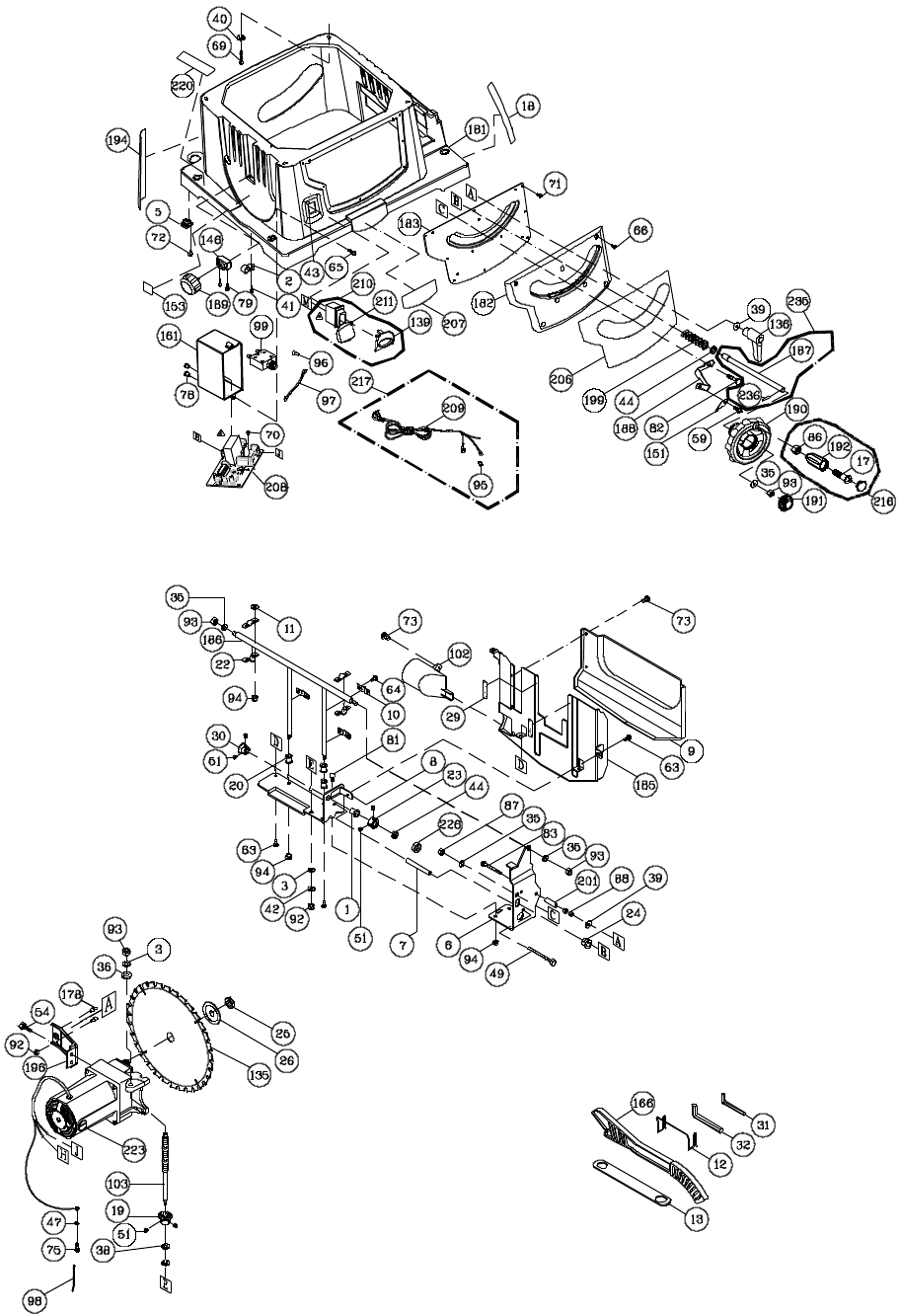
36
Table Saw
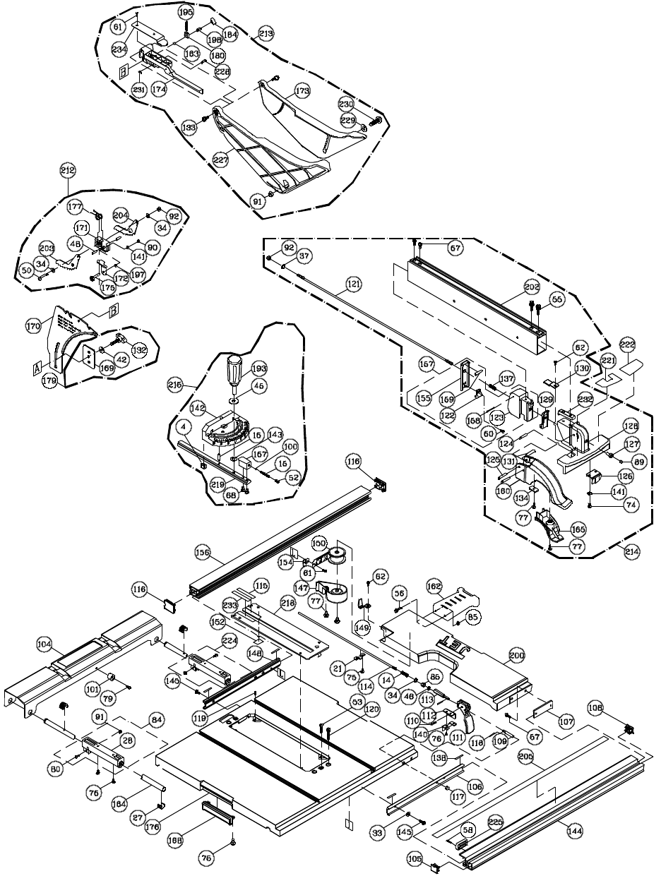
37
38
Mobile Stand
Index No. Part No. Description Size Qty
1 .............. JBTS10MJS-601......Carriage Bolt ....................................................M8x50........................ 2
2 .............. JBTS10MJS-602......Washer ............................................................Ø8.4x24x2 ................. 4
3 .............. JBTS10MJS-44 .......Flat Washer......................................................3/8x3/4x5/64 .............. 4
4 .............. JBTS10MJS-604......Wave Was her ...................................................WW-6 ........................ 1
5 .............. JBTS10MJS-605......Wave Washer...................................................WW-12 ...................... 2
6 .............. TS-1482081 ............Hex Cap Screw ................................................M6x40........................ 2
7 .............. JBTS10MJS-607......Bolt ..................................................................M6x50........................ 1
8 .............. JWBS18-108 ...........Hex Cap Screw ................................................M8x65........................ 4
9 .............. JBTS10MJS-609......Truss Head Screw ............................................M6x45........................ 1
10 ............ JBTS10MJS-610......Truss Head Tapping Screw ...............................M5-12x12 ................... 2
11 ............ JMS10SCMS-72 ......Pan Head Screw...............................................M5x8 ......................... 8
12 ............ JBTS10MJS-612......Pan Head Round Neck Screw ...........................M5x10........................ 1
13 ............ TS-1540041 ............Hex Nut............................................................M6 ............................. 2
14 ............ JBTS10MJS-89 .......Crown Nut ........................................................M6 ............................. 2
15 ............ TS-1541001 ............Nylon Insert Lock Nut ........................................M4 ............................. 7
16 ............ TS-1541011 ............Nylon Insert Lock Nut ........................................M5 ............................. 2
17 ............ TS-1541021 ............Nylon Insert Lock Nut ........................................M6 ............................. 3
18 ............ TS-1541031 ............Nylon Insert Lock Nut ........................................M8 ............................. 4
19 ............ JEB-137 ..................Hex Cap Screw ................................................M8x100 ...................... 2
20 ............ JBTS10MJS-620......Pan Head Screw...............................................M4x60 ........................ 4
21 ............ TS-1501071 ............Socket Head Cap Screw ...................................M4x25........................ 3
22 ............ JBTS10MJS-622......Pan Head Round Neck Screw ...........................M5x12........................ 2
23 ............ TS-1541041 ............Nylon Insert Lock Nut ........................................M10 ........................... 2
24 ............ JBTS10MJS-624......End Cap............................................................................................. 4
25 ............ JMS10SCMS-147 ....SHCS with Lock Washer & Flat Washer .............M5x40........................ 2
26 ............ JBTS10MJS-626......Latch Hook ......................................................................................... 1
27 ............ JBTS10MJS-627......Foot Pedal ......................................................................................... 1
28 ............ JBTS10MJS-628......Stand Handle ..................................................................................... 1
29 ............ JBTS10MJS-629......Center Shaft ....................................................................................... 2
30 ............ JBTS10MJS-630......End Plug ............................................................................................ 2
31 ............ JBTS10MJS-631......End Cap............................................................................................. 2
32 ............ JBTS10MJS-632......Collar ................................................................................................. 2
33 ............ JBTS10MJS-633......Wheel ..............................................................8”............................... 2
34 ............ JBTS10MJS-634......Link ................................................................................................... 2
35 ............ JBTS10MJS-635......Collar ................................................................................................. 4
36 ............ JBTS10MJS-636......Foot Pad ............................................................................................ 2
37 ............ JBTS10MJS-637......Handle Base ...................................................................................... 1
38 ............ JBTS10MJS-638......Spring ................................................................................................ 2
39 ............ JBTS10MJS-639......Rear Frame Assembly ........................................................................ 1
40 ............ JBTS10MJS-640......Front Frame Assembly ........................................................................ 1
41 ............ JBTS10MJS-641......End Plug ............................................................................................ 1
42 ............ JBTS10MJS-642......Release Handle .................................................................................. 1
43 ............ JBTS10MJS-643......Rod ................................................................................................... 2
44 ............ JBTS10MJS-644......Spring ................................................................................................ 1
45 ............ JBTS10MJS-645......Button ................................................................................................ 2
46 ............ JBTS10MJS-646......Handle Cover ..................................................................................... 1
47 ............ JBTS10MJS-647......Wing Nut ............................................................................................ 1
48 ............ JBTS10MJS-648......Leveling Foot Pad ............................................................................... 1
49 ............ JBTS10MJS-649......Bushing.............................................................................................. 4
50 ............ JBTS10MJS-650......Sleeve ............................................................................................... 2
51 ............ TS-1491151 ............Hex Cap Screw ................................................M10x90 ...................... 2
52 ............ TS-2286402 ............Pan Head Screw...............................................M6x40........................ 2
53 ............ JBTS10MJS-653......Handle Grip ........................................................................................ 1
54 ............ JBTS10MJS-654......Collar ................................................................................................. 2
55 ............ JBTS10MJS-655......Truss Head Tapping Screw ...............................M6-14x60 ................... 2
56 ............ TS-2284252 ............Pan Head Screw...............................................M4x25........................ 4
57 ............ JBTS10MJS-657......Bushing.............................................................................................. 4
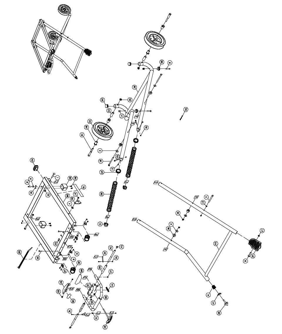
39
Mobile Stand
Index No. Part No. Description Size Qty
58 ............ JBTS10MJS-658......Bumper .............................................................................................. 2
59 ............ JBTS10MJS-659......Caution Label ..................................................................................... 1
60 ............ JBTS10MJS-660......Warning Label .................................................................................... 1
61 ............ JBTS10MJS-661......Warning Label .................................................................................... 1
62 ............ JBTS10MJS-662......Stand Top .......................................................................................... 1
63 ............ JBTS10MJS-663......Locking Cable Tie ............................................................................... 2
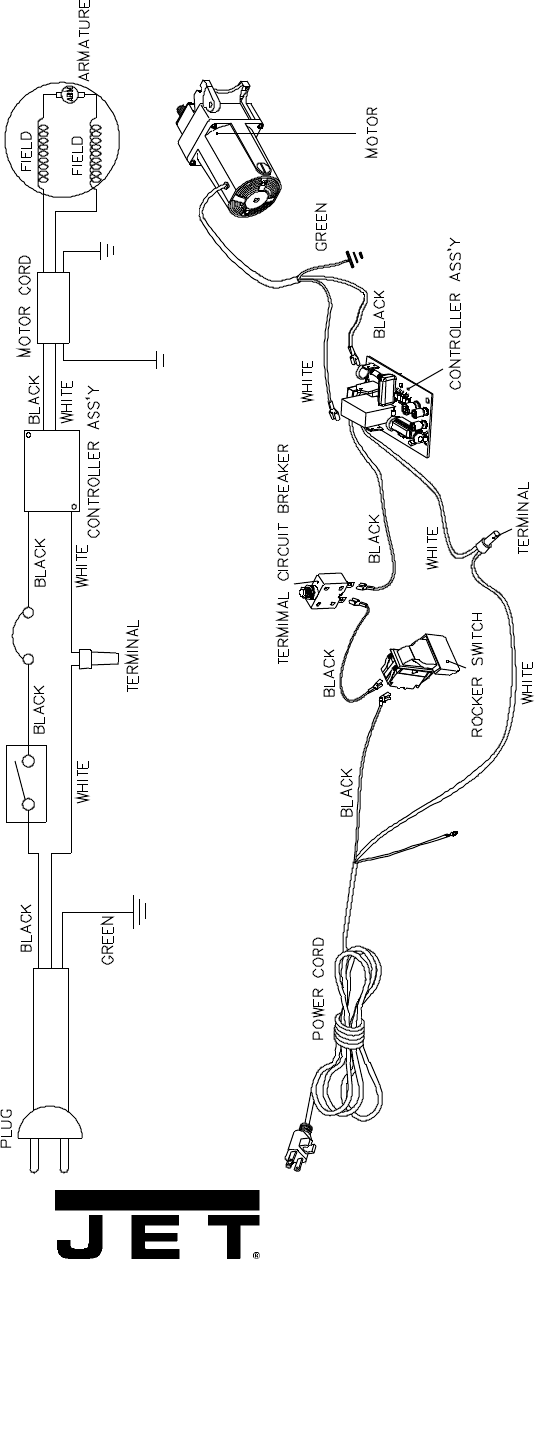
40
Wiring Diagram
WALTER MEIER (Manufacturing) Inc.
427 New Sanford Road
LaVergne, Tennessee 37086
Phone: 800-274-6848
www.waltermeier.com
