Jetlun RD77760 Zigbee Occupancy sensor User Manual RD77760UG 1 4
Jetlun (Shenzhen) Corporation Zigbee Occupancy sensor RD77760UG 1 4
Jetlun >
X5QRD77760_user manual_rev2

UserGuide
rev1.0
JetlunZigbeeOccupySensor
UserGuide
88PARKGROVEDRIVE|SOSANFRANCISCO|CA|94080|USA
T:+16504JETLUN(453‐8586)|F:+16503601977

Jetlun Corporation
Jetlun Occupancy Sensor User Guide rev 0.1 DRAFT 2
RD77760
© 2009 Jetlun Corporation. All rights reserved.
Notice: No part of this publication may be reproduced or transmitted in any form or by any
means, electronic or mechanical, including photocopying and recording, or stored in a database
or retrieval system for any purpose without the express written permission of Jetlun Corporation.
Jetlun Corporation reserves the right to make changes to this user’s guide at any time without
notice and assumes no responsibility for its use. Jetlun products and services can only be
ordered under the terms and conditions of Jetlun Corporation's applicable agreements. All of the
features described in this user’s guide may not be currently available. Refer to the most recent
product announcement for information about feature and product availability.
This user’s guide contains the most current information available at the time of publication.
When new and/ or revised information becomes available, this entire user’s guide is updated
and distributed to all registered users.
Trademarks, Product Names, and Service Names
Jetlun, the stylized J logo, and the Jetlun logo are either trademarks or registered trademarks of
Jetlun Corporation. All other product or service names are property of their respective owners.
http://www.jetlun.com

Jetlun Corporation
Jetlun Occupancy Sensor User Guide rev 0.1 DRAFT 3
RD77760
Table of Contents
1.0ABOUT THIS GUIDE .......................................................................................................... 4
1.1BECOMING FAMILIAR WITH THIS USER GUIDE ...................................................................... 4
1.1Quick Reference ........................................................................................................... 4
1.2Icon Descriptions .......................................................................................................... 4
1.3GETTING ADDITIONAL HELP ................................................................................................ 4
1.4SENDING FEEDBACK REGARDING THIS DOCUMENTATION .................................................... 4
2.0 PRODUCT OVERVIEW ....................................................................................................... 5
2.1PACKAGE CONTENTS ......................................................................................................... 5
2.2FRONT PANEL .................................................................................................................... 5
2.3 SIDE PANEL (RIGHT) .......................................................................................................... 6
2.4 SIDE PANEL (LEFT) ................................................................................................................. 7
3.0INSTALLING THE JETLUN OCCUPY SENSOR ............................................................... 8
3.1 INSTALL THE OCCUPY SENSOR ........................................................................................... 8
3.1.1 Join the Network ............................................................................................................. 8
3.1.2 Leave the network .......................................................................................................... 8
3.3 TROUBLESHOOTING .......................................................................................................... 8
4.0 TECHNICAL SPECIFICATIONS ....................................................................................... 10
List of Figures
Figure 1: Front Panel of the Occupy Sensor .................................................................................. 6
Figure 2: Right Side Panel of the Occupancy Sensor ................................................................... 6
Figure 3: Left Side Panel of Occupy Sensor .................................................................................. 7
List of Tables
Table 1: Where to find information in this User Guide ................................................................... 4
Table 2: Icon descriptions ............................................................................................................... 4
Table 3: Back Panel of the Occupancy Sensor Description .......................................................... 7
Table 4: Back Panel of the Occupancy Sensor Description .......................................................... 7
Jetlun Corporation
Jetlun Occupancy Sensor User Guide rev 0.1 DRAFT 4
RD77760
1.0 ABOUT THIS GUIDE
1.1 Becoming familiar with this User Guide
1.1 Quick Reference
The Jetlun Occupancy Sensor (RD77760) User Guide describes the following:
Table 1: Where to find information in this User Guide
Planning and Installing the Jetlun Occupy Sensor Chapter 2 and 3
1.2 Icon Descriptions
While reading through the User Guide, you may see various icons that call attention to
specific items. Below is a description of these icons:
Table 2: Icon descriptions
NOTE: This mark indicates that there is a note of interest and is
something that you should pay attention to while using the
product.
IMPORTANT: This mark identifies an indication that you should
watch for, or reiterates something that you should always keep
in mind.
WARNING: This exclamation point indicates that there is a
caution or warning and may be something that could damage
your property or project.
1.3 Getting Additional Help
To get information or assistance for problems that you encounter, please contact Jetlun
Technical Support by emailing support@jetlun.com.
Please always include with all inquiries the following information:
• Product name, model number, part number (if applicable) and serial number
• A description of the devices connected to your Gateway or a system configuration
• The circumstances surrounding the error or failure
• A detailed description of the problem and what has been done to try to resolve it
1.4 Sending Feedback regarding this Documentation
We welcome your feedback on Jetlun Gateway documentation. This includes feedback on the
structure, content, accuracy, or completeness of our documents, and any other comments you
may have. Please send your comments to docs@jetlun.com.

Jetlun Corporation
Jetlun Occupancy Sensor User Guide rev 0.1 DRAFT 5
RD77760
2.0 PRODUCT OVERVIEW
Thank you for choosing the Occupancy Sensor (RD77760). The Occupancy Sensor is
designed to communicate with JIM Gateway via Radio Frequency (RF) to provide
remote control of your zigbee-enalbe device such as appliance module.
The Occupancy Sensor is a Zigbee® enable device. In the Zigbee® network, the
Occupy Sensor is designed to act as enddevice. Set a chain of events using the status
of occupy sensor to control groups of zigbee-enalbe devices in the gateway network. It
also can alert through email or SMS when battery volume is low.
It has the features as following:
z Join/Leave Network LED
z Power LED
z Occupy/Unoccupied LED
z This is a Zigbee® controller
z Two way communication
z RF Reliability
z Compatible with other Zigbee enabled devices
2.1 Package Contents
When you first open the box, please check and confirm that the following items are all
included:
• 1x Occupancy Sensor RD77760
• 1x Quick Installation Guide
Contact the retailer where you made your purchase if any of these parts are incorrect,
missing or damaged. Keep the carton, including the original packaging materials in case
you need to return the unit for repair.
2.2 Front Panel
Jetlun Corporation
Jetlun Occupancy Sensor User Guide rev 0.1 DRAFT 6
RD77760
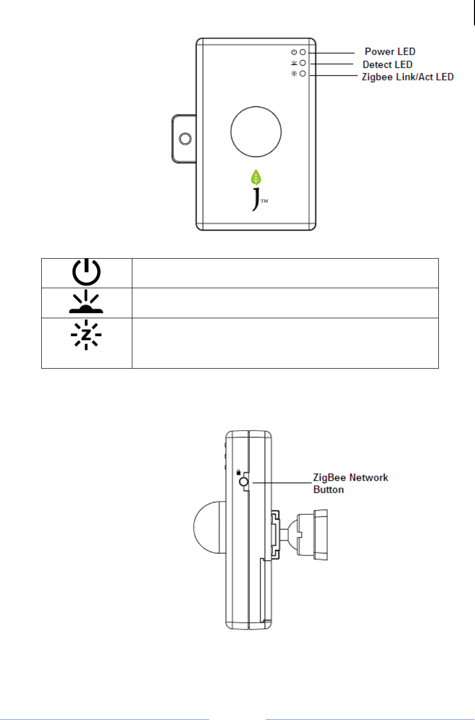
Figure 1: Front Panel of the Occupy Sensor
The Power LED lights up RED when the battery volume is
low.
The Detect LED lights up Green when some one stands in
front of sensor.
The Zigbee ACT LED blinks green when Occupancy senseor
receives/sends the data.
The Zigbee ACT LED is solid green for 300 seconds when
Occupancy sensor joins the zigbee network.
2.3 Side Panel (Right)
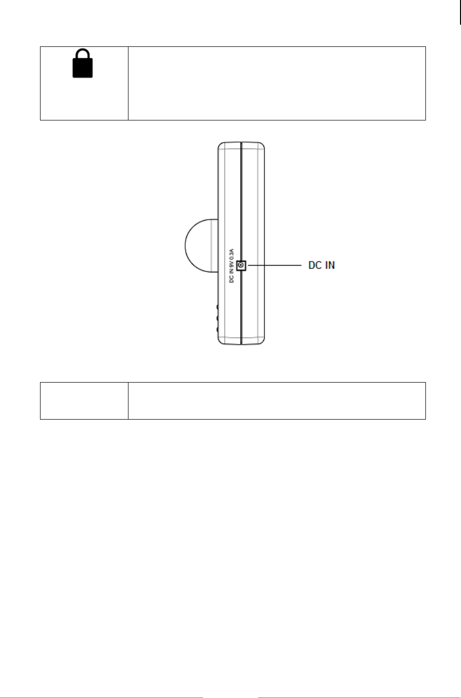
Figure 2: Right Side Panel of the Occupancy Sensor
Jetlun Corporation
Jetlun Occupancy Sensor User Guide rev 0.1 DRAFT 7
RD77760
Table 3: Back Panel of the Occupancy Sensor Description
The Zigbee Network button is applied for the Occupancy
Sensor to join or leave the network.
Press the Zigbee Network button once to join the network if
the sensor is not in the network.
To remove the sensor from the network, press the Zigbee
Network button once to leave the network.
2.4 Side Panel (Left)
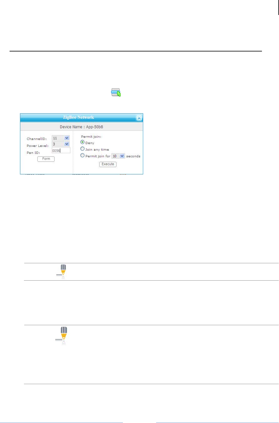
Figure 3: Left Side Panel of Occupy Sensor
Table 4: Back Panel of the Occupancy Sensor Description
DC IN The DC IN is used to provide the power for Occupancy by
DC adapter when no battery in the sensor.
The output voltage for adapter is 9V, output current is 0.3A

Jetlun Corporation
Jetlun Occupancy Sensor User Guide rev 0.1 DRAFT 8
RD77760
3.0 INSTALLING THE JETLUN OCCUPY SENSOR
Follow these quick steps to install your Jetlun Zigbee Occupy Sensor.
3.1 Install the Occupy Sensor
3.1.1 Join the Network
 STEP 1: Press the Zigbee network button for 3-5 seconds and release the button.
The Zigbee Act LED is blinking.
 STEP 2: The Occupancy Sensor will join the network within 1 minute. The Zigbee
ACT LED should be solid green for 300 seconds.
NOTE: If the Occupancy Sensor fails to join the ZigBee network,
please enter the Gateway utility web interface and check the
following items:
1. The Zigbee network is formed.
2. The Zigbee network allows the Zigbee device to join the
network.
Retry Step 1
3.1.2 Leave the network
 STEP 1: Press and hold the Zigbee network button for 8 -10 seconds then release the
button. The Zigbee Act LED is blinking for about 3 seconds and then it is
off.
 STEP 2: The Occupancy Sensor leaves the network successfully when the link LED
is off.
3.3 TROUBLESHOOTING
1 Q: The Occupancy Sensor is failed to join the network?
A: Check the configuration of Gateway or RD75613 and assure that the network is
formed. Then refer to the 3.1.1 join the network part to retry join the network
2 Q: The Power LED is solid red or blinking red?
A: The volumne of battery is low and you should change the battery.
Change out battery procesure:
 STEP 1: Screw out the screw in the bottom panel using screwdriver
 STEP 2: Open the bottom panel.
Jetlun Corporation
Jetlun Occupancy Sensor User Guide rev 0.1 DRAFT 9
RD77760
 STEP 3: Use the new battery instead the old one
 STEP 4: Close the bottom panel and screw the screw.
3 Q: Join the Occupancy sensor to the Gateway Zigbee network through RD75613?
A: The procedure is following:
 STEP 1: Form the Zigbee Network through the RD75613.
1. Enter the Gateway utility web Home Area Network > Control interface
2. Select the RD75613 (Appliance module) whose Zigbee network the Occupancy
sensor will join and click the button
3. Enter the Zigbee network button, and enter the Chanel ID, Power Level and Pan ID. (If
the Zigbee network is formed, you can directly jump to item 5.)
Channel ID is digit from 11 to 26
Power Lever is digit from 1 to 3
Pan ID must be 4 bits Hex
4. Click the Form button. When the network is formed, the name of Form button is
changed to “Leave”.
5. Select the Permit join choice and click Execute button.
Explain of permit join choices:
Deny: No sensors can join the network
Join any time: All sensors can zigbee network at any time.
Permit join for XX seconds: Sensors can join the network within XX seconds.
NOTE: Permit join setting should be reset when the
appliance module is rebooting.
 STEP 2: Occupancy sensor joins the network
1. Press and release the Zigbee network button once. The Zigbee ACT LED should be
blinking.
2. The occupancy Sensor will join the network within 1 minute. The Zigbee ACT LED
should be solid green for 300 seconds
NOTE: If the Occupancy Sensor fails to join the ZigBee
network, please enter the Gateway utility web home area
network > Control > Zigbee network interface (Refer the Step
1) and check the following items:
1. The Zigbee network is formed.
2. The Zigbee network allows the Zigbee device to join the
network.
3. Retry this procedure

Jetlun Corporation
Jetlun Occupancy Sensor User Guide rev 0.1 DRAFT 10
RD77760
 STEP 3: Occupancy sensor leaves the network
1. Press and hold the Zigbee network button for 3-5 seconds.
2. The Occupancy Sensor has left the network successfully when the ACT LED is off.
4.0 TECHNICAL SPECIFICATIONS
Part Number RD77760
Product Name Jetlun Zigbee Occupancy Sensor
Description An integrated Zigbee motion detector
Standard
Compliance Zigbee Smart Energy or Home Automation Profile
IEEE 802.15.4 for Zigbee
Frequency Band Zigbee: 2.4 GHz
Transport Mode Zigbee: Up to 200 kbps
Range Zigbee: Up to 100 ft (30 m)
LEDs Power,Zigbee Act/Link/Security LED, Signal LED
Detection distance Max 16 ft
Operating Temp -32ºF to 113ºF (0ºC to 45ºC)
Operating Humidity 10 to 85% non-condensing
Storage Temp -4ºF to 176ºF (-20ºC to 80ºC)
Storage Humidity 5 to 95% non-condensing
Dimensions 90x56 x 21mm (L x W x H)
Weight 0.099kg (0.21 lbs)
Operating Voltage 9V DC / 9V battery
Safety and EMI FCC/UL/cUL/CE
Zigbee SE/HA certification
WEEE RoHS Compliant

Glossary
Zigbee is a low-speed, low powered 802.15.4 wireless mesh standard established by the Zigbee Alliance.
The Zigbee Alliance is a non-profit Standard organization made up 300+ companies driving
development of ZigBee wireless technology. For more information, visit www.zigbee.org. Zigbee is the
only wirleess technology standard that has been listed under NIST as 1 of the 13 Smart Grid
interoperability standards. For more information about NIST, please visit www.nist.gov. ...... 6, 10, 11, 12
z FCC Notices
1. The manufacturer is not responsible for any radio or TV interference caused by unauthorized
modifications to this equipment. Such modifications could void the user’s authority to operate
the equipment.
2. This device complies with Part 15 of the FCC Rules. (1) This device may not cause harmful
interference, and (2) this device must accept any interference received, including interference
that may cause undesired operation.
3. This equipment complies with FCC RF radiation exposure limits set forth for an
uncontrolled environment. This equipment should be installed and operated with
a minimum distance of 20 centimeters between the radiator and your body.
NOTE: This equipment has been tested and found to comply with the limits for a Class B digital
device, pursuant to part 15 of the FCC Rules. These limits are designed to provide reasonable
protection against harmful interference in a residential installation. This equipment generates
uses and can radiate radio frequency energy and, if not installed and used in accordance with
the instructions, may cause harmful interference to radio communications. However, there is no
guarantee that interference will not occur in a particular installation. If this equipment does
cause
harmful interference to radio or television reception, which can be determined by turning the
equipment off and on, the user is encouraged to try to correct the interference by one or more of
the following measures:
—Reorient or relocate the receiving antenna.
—Increase the separation between the equipment and receiver.
—Connect the equipment into an outlet on a circuit different from that to which the receiver is
connected.
—Consult the dealer or an experienced radio/TV technician for help.
Notes

Jetlun Corporation
88 Parkgrove Drive
So San Francisco CA 94080 USA
www.jetlun.com
sales@jetlun.com
650-4JETLUN