JiangSu Nikota Electrical Commodity GDO Garage Door Opener User Manual
JiangSu Nikota Electrical Commodity CO., Ltd Garage Door Opener
Users Manual
Owner's Manual
1/2 HP
GARAGE DOOR OPENER
For Residential Use Only
ENGLISH
CAUTION:
Read and follow all safety rules
and operating instructions before
first use of this product.
Fasten the manual near the garage
door after installation.
Made in China
WWW.NIKOTAUSA.COM
12345
WORK
SHIFT
YAKO

When you see these Safety Symbols and Signal
Words on the following pages, they will alert you to
the possibility of if you do
not comply with the warnings that accompany them.
The hazard may come from something mechanical
or from electric shock. Read the warnings carefully.
serious injury or death
When you see this Signal Word on the following
pages, it will alert you to the possibility of damage to
your garage door and/or the garage door opener if
you do not comply with the cautionary statements
that accompany it. Read them carefully.
TABLE OF CONTENTS
Safety symbol and signal word review.........................2
Preparing your garage door ........................................3
Tools needed................................................................3
Planning ......................................................................4
Carton inventory...........................................................5
Hardware inventory......................................................6
Assembly 7-10
Assemble the rail and install trolley.............................7
Fasten rail to motor uniit and install idler pulley .........8
Install chain/cable and attach sprocket cover........... 9
Tighten the chain.......................................................10
Installation 10-23
Installation safety instructions....................................10
Determine the header bracket location......................11
install the header bracket..........................................12
At tach the r ail to the header bracket.......................13
Position the open er....................................................14
Hang the opener ....................................................... 15
Install the door control............................................... 16
Install the light and lens..............................................17
At tach the emergency release rope and handle....... 17
Electrical requirements.............................................. 18
Install the safety reversing sensor....................... 19-21
Fasten the door bracket............................................22
Connect the door arm to the tro lley .......................23
Introduction 2-6
Adjust the travel limits ...............................................24
Test the safety reversal system.................................l25
Test the safety reversing sensor ................................25
Operation 26-29
Operation safety instructions.....................................26
Using your garage door opener ................................26
Using the wall-mounted Door Control.......................27
To open the door manually........................................27
Care of your garage door opener..............................28
Having a problem?.................................................... 29
Programming
30
To add a hand-held remote control ...........................30
To erase all codes.....................................................30
3-Function Remotes..................................................30
Repair Parts
31-32
Rail assembly parts...................................................31
Installation parts ........................................................31
Motor unit assembly parts......................................... 32
Warranty 33
Service Numbers
Back
cover
This garage door opener has been designed and tested to offer safe service provided it is installed, operated,
maintained and tested in strict accordance with the instructions and warnings contained in this manual.
Adjustment
24-25
INTRODUCTION
Safety Symbol
and Signal Word Review
WARNING
CAUTION
WARNING
Mechanical
Electrical
2
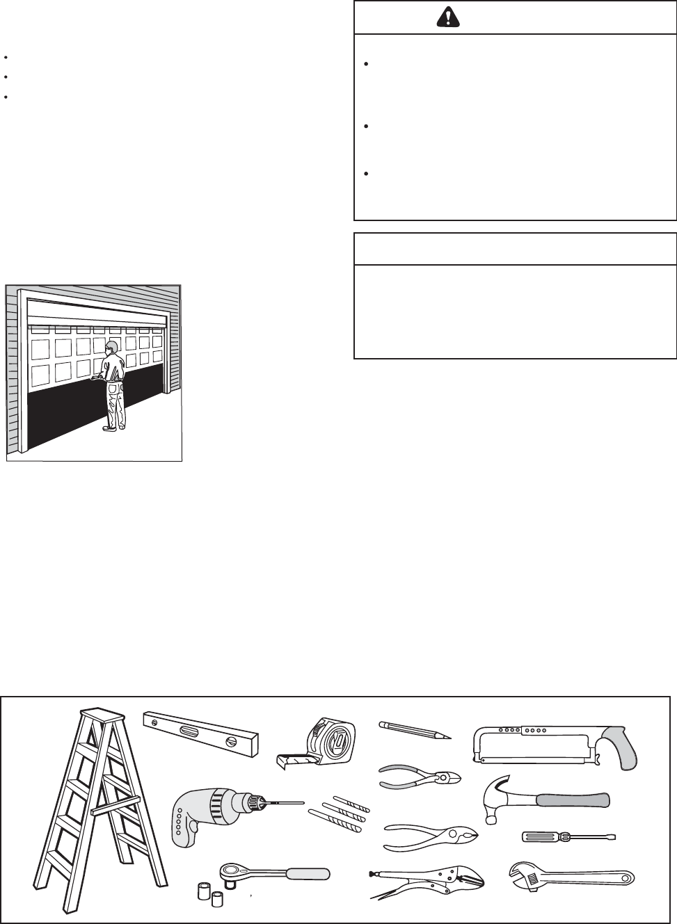
Disable locks.
Remove any ropes connected to garage door.
Complete the following testtomakesureyour
garage door is balanced and is not sticking or
binding:
1. Lift the door about halfway as shown. Release
the door. If balanced, it should stay in place
supported entirely by its springs.
2. Raise and lower the door to see if there is any
binding or sticking.
If your door binds, sticks, or is out of balance, call
a trained door systems technician.
Preparing your garage door
Before you begin:
WARNING
call a trained door systems technician ifALWAYS
garage door binds, sticks, or is out of balance. An
unbalanced garage door may not reverse when
required.
NEVER try to loosen, move or adjust garage door, door
springs, cables, pulleys, brackets or their hardware, all
of which are under tension.EXTREME
Disable ALL locks and remove ALL ropes connected to
garage door BEFORE installing and operating garage
door opener to avoid entanglement.
To prevent possible SERIOUS INJURY OR DEATH:
To prevent damage to garage door and opener:
ALWAYS disable locks before installing and operating
the opener.
ONLY operate garage door opener at 110V, 60 Hz to
avoid malfunction and damage.
CAUTION
Sectional Door
Tools needed
During assembly, installation and adjustment of the
opener, instructions will call for hand tools as
illustrated below.
Stepladder
1/2" 7/16" and 1/4" Sockets
and Wrench
Carpenter's
Level
Drill
Tape Measure
3/16", 5/16" and
5/32" Drill Bits
Pencil
Wire Cutters
Pliers
Locking pliers
Hack Saw
Claw Hammer
Screwdriver
Adjustable End Wrench
3
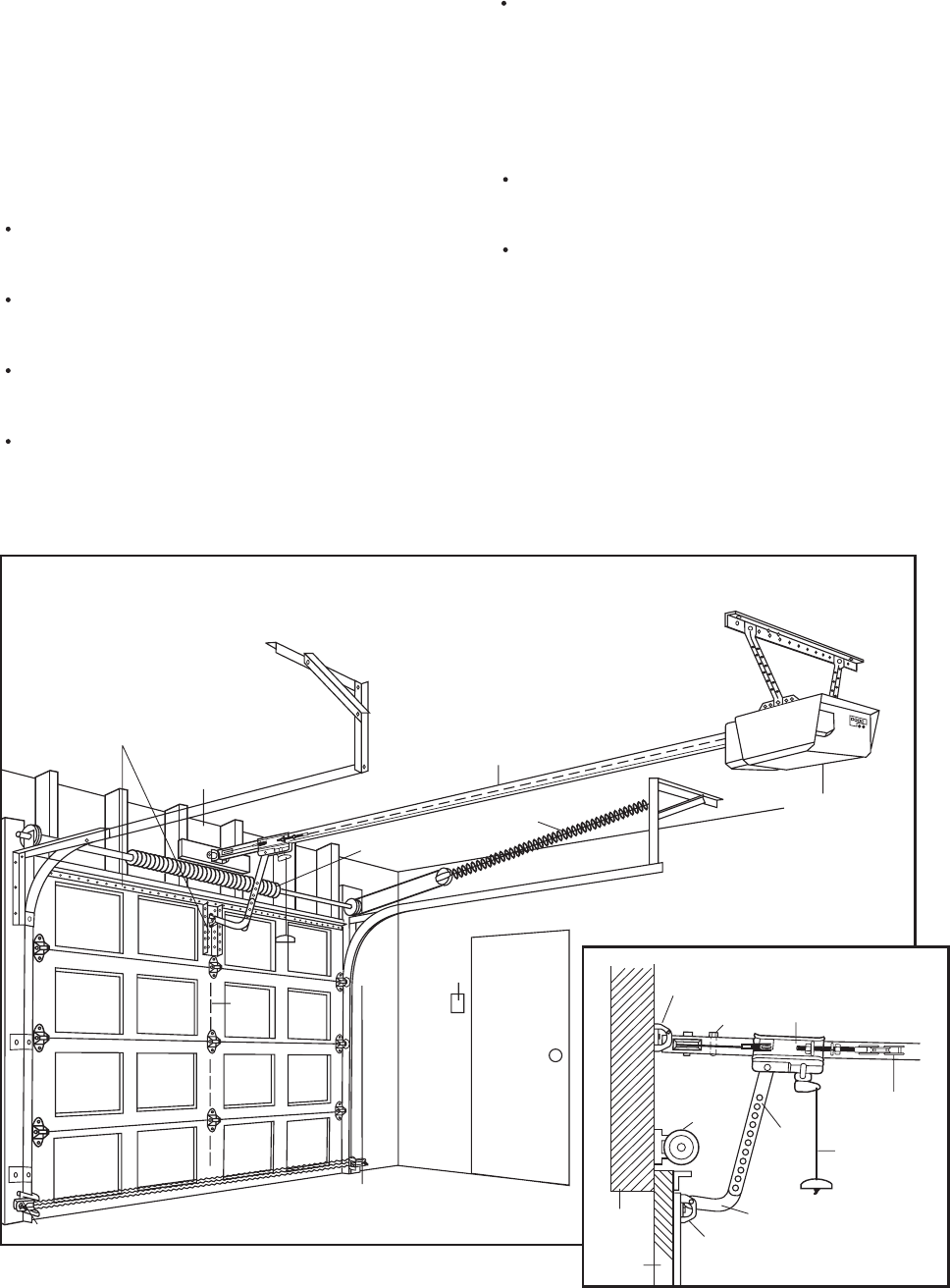
Planning
Identify the type and height of your garage door.
Survey your garage area to see if any of the
conditions below apply to your installation. Additional
materials may be required. You may find it helpful to
refer back to this page and the accompanying
illustrations as you proceed with the installation of
your opener.
Depending on your requirements, there are several
installation steps which may call for materials or
hardware not included in the carton.
Installation Step 1 Look at the wall or ceiling
above the garage door. The header bracket must
be securely fastened to structural supports.
Installation Step 5 Do you have a finished ceiling
in your garage? If so, a support bracket and
additional fastening hardware may be required.
Installation Step 10 Depending upon garage
construction, extension brackets or wood blocks
may be needed to install sensors.
Installation Step 10 Alternate floor mounting of
the safety reversing sensor will require hardware
not provided.
-
-
-
-
Look at the garage door where it meets the floor.
Any gap between the floor and the bottom of the
door must not exceed 1/4". Otherwise, the safety
reversal system may not work properly. See
Adjustment Step 3. Floor or door should be
repaired.
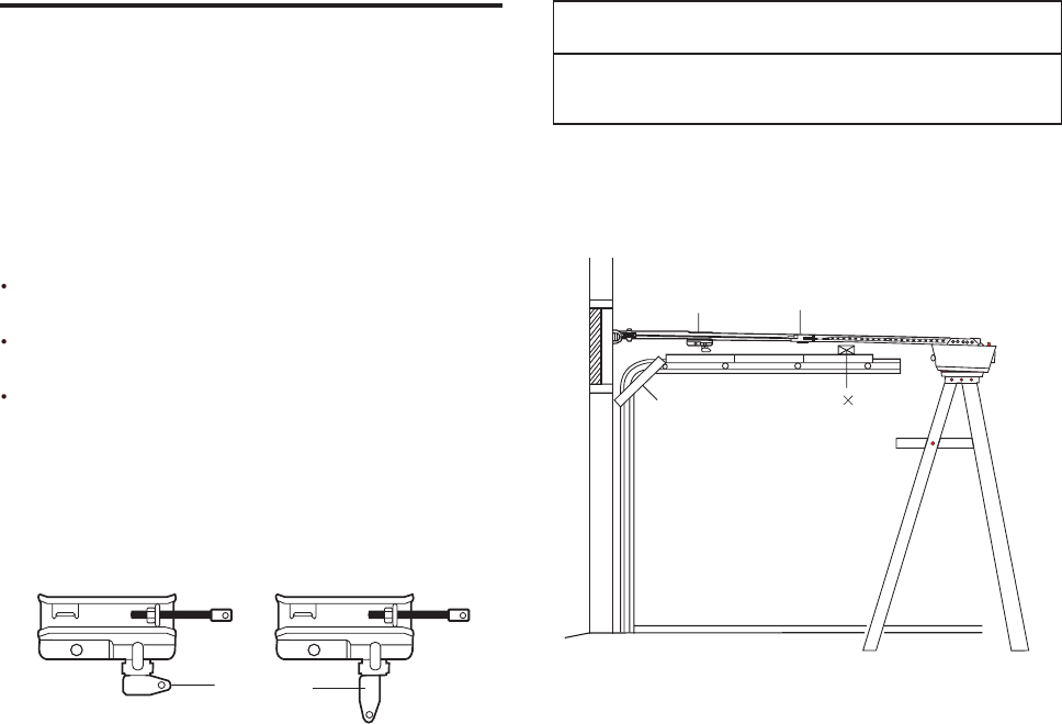
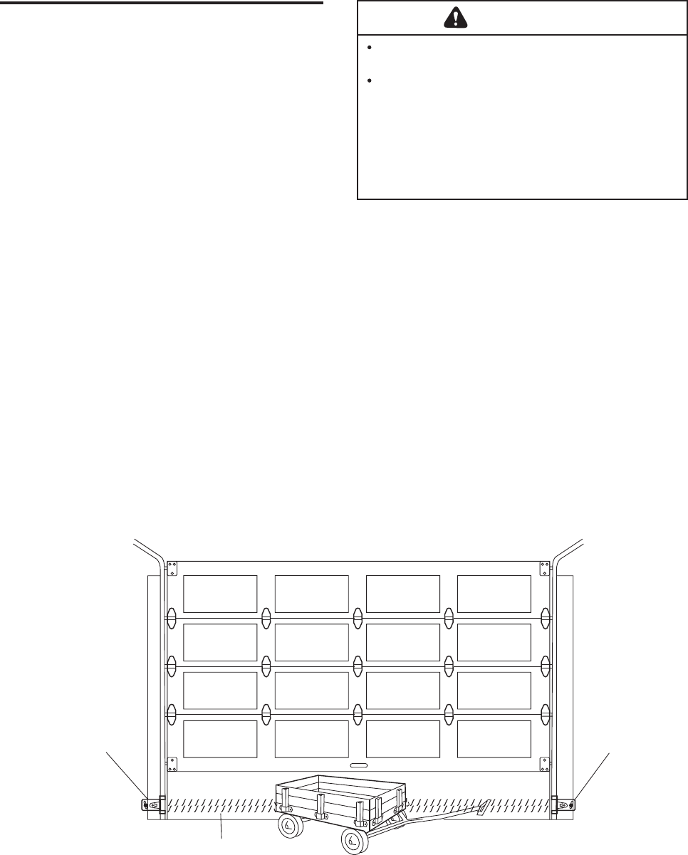
SECTIONAL DOOR INSTALLATIONS
Do you have a steel, aluminum, fiberglass or glass
panel door? If so, horizontal and vertical reinforce-
ment is required (Installation Step 11).
The opener should be installed above the center of
the door. If there is a torsion spring or center
bearing plate in the way of the header bracket, it
may be installed within 4 feet to the left or right of
the door center. See Installation Steps 1 and 11.
SECTIONAL DOOR INSTALLATION
Horizontal and vertical reinforcement
is needed for lightweight garage doors
(fiberglass, steel, aluminum, door with
glass panels, etc.). See page 22 of details.
Header Wall
Door
Center
Rail
Extension Spring
OR
Torsion Spring
Wall-
mounted
Door
Control
Access Door
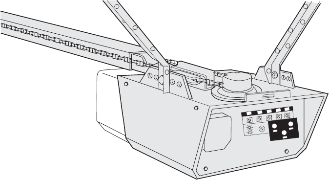
Motor unit
FINISHED CEILING
Support bracket &
fastening hardware
is required.
See page 15.
Safety Reversing Sensor
Gap between floor
and bottom of door
must not exceed 1/4".
Safety
Reversing
Sensor
Header
Bracket
Trolley
Stop Bolt Trolley
CLOSED POSITION
Chain
Garage
Door
Spring
Emergency
Release
Rope & Handle
Straight
Door
Arm
Curved
Door
Arm
Door
Bracket
Header
Wall
Garage
Door
4
5
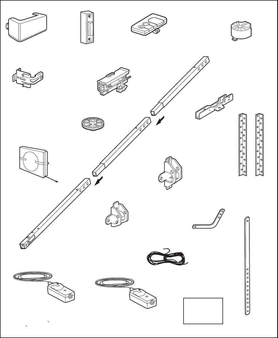
Carton lnventory
Your garage door opener is packag d in one carton
which contains the motor unit and the parts illustrated
below. Note that accessories will depend on the
model purchased. If anything is missing, caretully
check the packing material. Parts may be stuck in the
efoam. Hardware for assembly and installation is
shown on the next page. Save the carton and
packing material until installation and adjustment is
complete.
Chain and CableChain and Cable
Chain
Idler Pulley
Chain
Idler Pulley
Trolley
Rail
Center/Back
Sections
Rail
Center/Back
Sections
Rail
Front (header)
Section
Rail
Front (header)
Section
Hanging BracketsHanging Brackets
Header BracketHeader Bracket Curved Door
Arm Section
Curved Door
Arm Section
2-Conductor Bell Wire
White & White/Red
2-Conductor Bell Wire
White & White/Red
Safety Sensor Emitter
with 2-Conductor White & White with fine
black dashdotted
Safety Sensor Emitter
with 2-Conductor White & White with fine
black dashdotted
Safety Labels
and
Literature
Safety Labels
and
Literature
Straight Door
Arm Section
Straight Door
Arm Section
Safety Sensors
Bracket
Safety Sensors
Bracket
Door Control ButtonDoor Control Button
Three-Function Remote Control
with Visor Clip
Three-Function Remote Control
with Visor Clip Sprocket CoverSprocket Cover
Light LensLight Lens
Nikota
Door BracketDoor Bracket
U BracketU Bracket
Safety Sensor Receiver
with 3-Conductor White White /thick black
dashdotted White/black dot
Safety Sensor Receiver
with 3-Conductor White White /thick black
dashdotted White/black dot
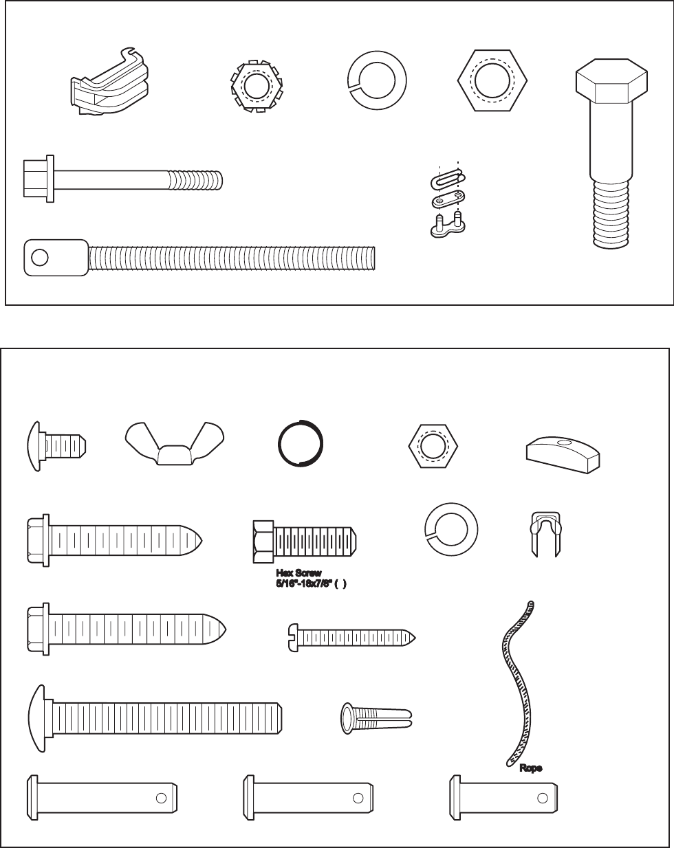
Hardware Inventory
Separate all hardware and group as shown below for the assembly and installation procedures.
ASSEMBLY HARDWARE
Chain Spreader (2)Chain Spreader (2) Lock Nut
1/4"-20 (2)
Lock Nut
1/4"-20 (2)
Bolt 1/4"-20 x 1-3/4" (2)Bolt 1/4"-20 x 1-3/4" (2)
Trolley Threaded Shaft (1)Trolley Threaded Shaft (1)
Lock Washer
3/8" (1)
Lock Washer
3/8" (1)
Nut
3/8" (1)
Nut
3/8" (1)
Master
Link (2)
Master
Link (2) Idler Bolt (1)Idler Bolt (1)
NOTICE
INSTALLATION HARDWAREINSTALLATION HARDWARE
Carriage Bolt
1/4"-20x1/2" (2)
Carriage Bolt
1/4"-20x1/2" (2)
Wing Nut
1/4"-20 (2)
Wing Nut
1/4"-20 (2)
Ring
Fastener (3)
Ring
Fastener (3)
Nut 5/16"-18 (8)Nut 5/16"-18 (8) Handle
Lag Screw
5/16"-9x1-5/8" (2)
Lag Screw
5/16"-9x1-5/8" (2)
Lag Screw
5/16"-18x1-7/8" (2)
Lag Screw
5/16"-18x1-7/8" (2)
Carriage Bolt
5/16"-18x2-1/2" (2)
Carriage Bolt
5/16"-18x2-1/2" (2)
Clevis Pin
5/16"x1-1/2" (1)
Clevis Pin
5/16"x1-1/2" (1)
Clevis Pin
5/16"x1-1/4" (1)
Clevis Pin
5/16"x1-1/4" (1)
Clevis Pin
5/16"x1 (1)
Clevis Pin
5/16"x1 (1)
Screw 6ABx1-1/2” (2)Screw 6ABx1-1/2” (2)
Dry Wall Anchors (2)Dry Wall Anchors (2)
Lock Washer 5/16" (7)Lock Washer 5/16" (7)
Insulated
Staples (30)
Insulated
Staples (30)
6
4
7
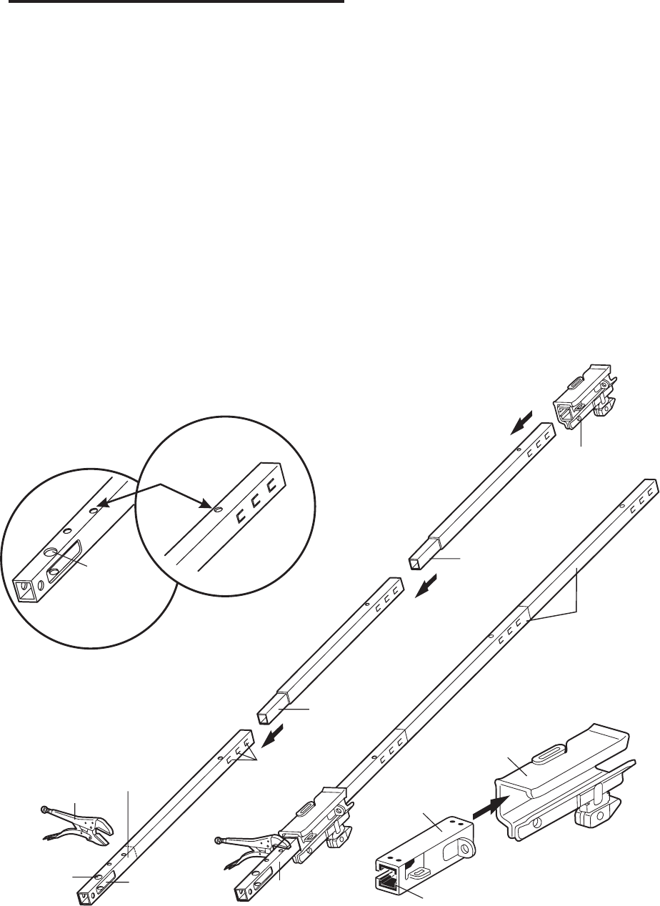
ASSEMBLY STEP 1
Assemble the Rail & Install the Trolley
To avoid installation difficulties, do not run the
garage door opener until instructed to do so.
2. Align the rail sections on a flat surface exactly as
shown and slide the tapered ends into the larger
ones. Tabs along the side will lock into place.
3. Place the motor unit on packing material to protect
the cover, and rest the back end of the rail on top.
For convenience, put a support under the front
end of the rail.
4. As a temporary trolley stop, clamp a locking pliers
onto the rail, 8" from the center of the idler pulley
hole, as shown.
5. Check to be sure there are 4 white plastic wear
pads inside the inner trolley. If they became loose
during shipping, check all packing material. Snap
them back into position as shown.
6. Connect the inner and outer trolleys as shown.
7. Slide the trolley assembly along the rail from the
back end to the locked pliers.
KEEP LARGER
HOLE ON TOP
KEEP LARGER
HOLE ON TOP
FRONT RAIL
(TOP)
KEEP SMALL HOLES
ALONG OPPOSITE EDGE
OF RAILS
KEEP SMALL HOLES
ALONG OPPOSITE EDGE
OF RAILS
BACK RAILBACK RAIL
(TOP)
8" Distance from
ldler Pulley Hole
8" Distance from
ldler Pulley Hole
Locking PliersLocking Pliers
Idler
Pulley
Hole
Idler
Pulley
Hole Window
Cut-Out
Window
Cut-Out
Tabs
Tapered
End
Tapered
End
Inner Trolley
Front Rail
(TO DOOR)
Front Rail
(TO DOOR) Wear PadsWear Pads
Outer Trolley
Back Rails
(TO MOTOR UNIT)
Back Rails
(TO MOTOR UNIT)
Tapered
End
Tapered
End
Trolley
The front rail has a cut out window at the door end
(see Illustration). The hole Above This Window is
larger on the top of the rail than on the bottom. A
smaller hole 3-1/2" away is close to the rail edge.
Rotate the back rail so it has a similar hole close to
the edge, about 4-3/4" from the far end. Aopposite
3-piece rail uses two back rails.
1. Remove the straight door arm and clevis pin
packaged inside the front rail and set aside for
Installation Step 12.
8
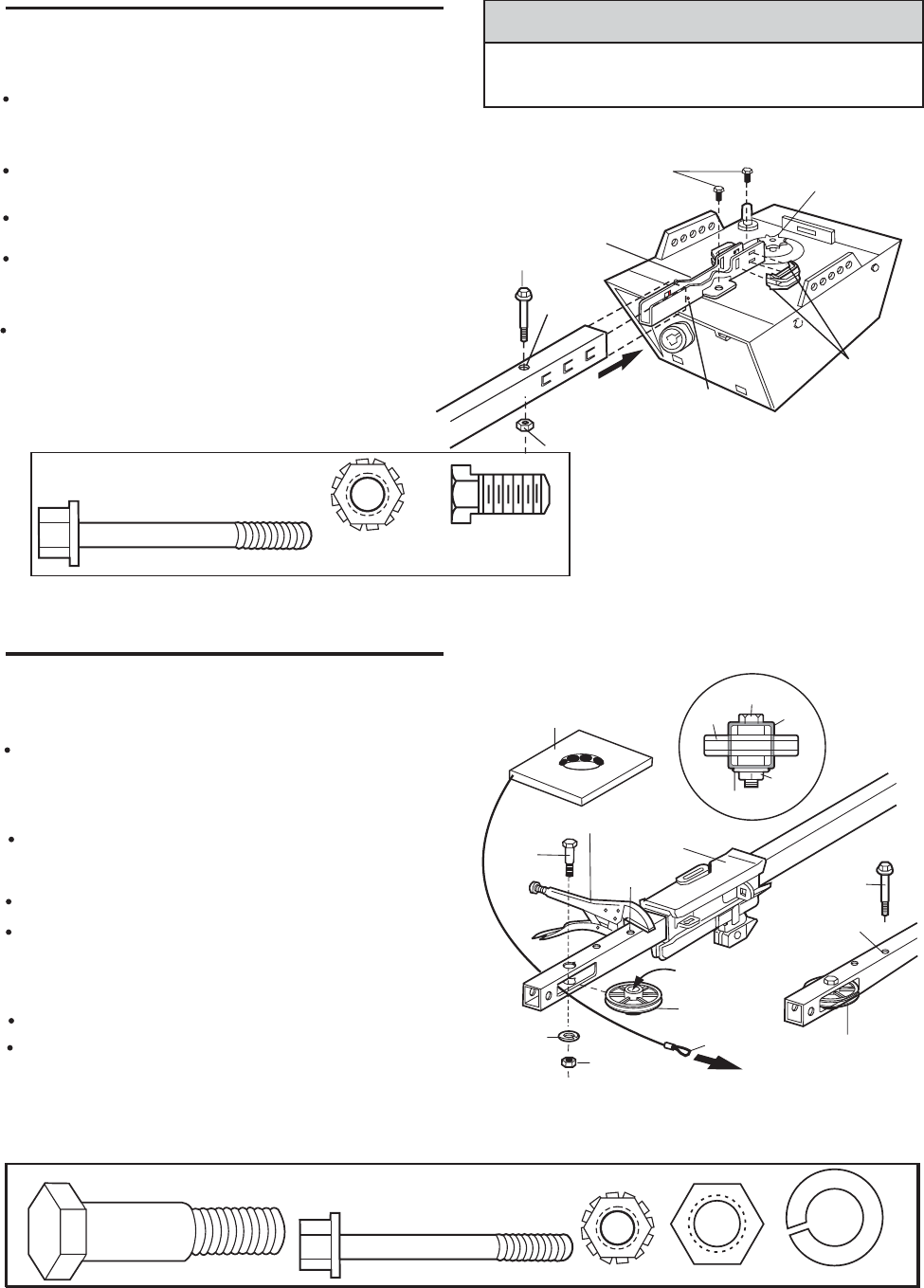
ASSEMBLY STEP 2
Fasten the Rail to the Motor Unit
Insert a 1/4"-20x1-3/4 bolt into the cover protection
Bolt hole on the back end of the rail as shown.
Tighten securely with a 1/4"-20 lock nut.
. Remove the two screws from the top of the motor
unit.
Attach spreaders to the U bracket by snapping
them into place.
Place the U bracket, flat side down, on the motor
nit and align the bracket boles with the screw
U
holes. Fasten with the previously removed screws.
Align the rail assembly with the top of the motor
unit. Slide the rail end onto the U-bracket, all the
way to the stops that protrude on the top and sides
of the bracket.
HARDWARE SHOWN ACTUAL SIZE
Bolt 1/4"-20 1-3/4
Lock Nut
1/4"-20
CAUTION
To avoid serious damage to garage door opener, use
only those screws mounted in the top of the opener.
ASSEMBLY STEP 3
Install the ldler Pulley
Lay the chain/ca le beside the rail, as shown.b
grasp the end with the cable loop and pass
approximately 12" of cable through the window.
Allow it to hang until Assembly Step 5.
Remove the tape from the idler pullty. The inside
center should be pre-greased. If dry, regrease to
ensure proper operation.
Place the idler pulley into the window as shown.
Insert the idler bolt from the top through the rail
and pulley. Tighten with a 3/8" lock washer and nut
underneath the rail until the lock washer is
compressed.
Rotate the pulley to be sure it spins freely.
Insert a 1/4"-20 1-3/4 bolt into the trolley stop hole
in the front of the rail as shown. Tighten securely
with a 1/4"-20 lock nut.
Bolt
"U" Bracket
Cover
Protection
Bolt Hole
Screws Motor Unit
Sprocket
SLIDE RAIL TO STOPS
ON TOPAND SIDES
OF BRACKET
Lock Nut
Hook Spreader
into Back Slots,
then Snap Tab
Inoo Front Slot
Chain and
Cable
Locking Pliers
Idler
Bolt
Trolley
Trolley
Stop Hole
3/8" Look
Washer
Grease
lnside Pulley
ldler
Pulley
Cable Loop
Bolt
Trolley
Stop Hole
Idler Pulley
3/8" Nut
Bolt
Pulley Rail
Nut
Washer
HARDWARE SHOWN ACTUAL SIZE
Bolt 1/4"-20 1-3/4
Lock Nut 1/4"-20
ldler Bolt
Nut 3-8" Lock Washer 3-8"
Bolt 1/4"-20 x 1-3/4" (2)Bolt 1/4"-20 x 1-3/4" (2)
Hex Sorew
5/16 - 18
" x7/16" (2)" x7/16" (2)
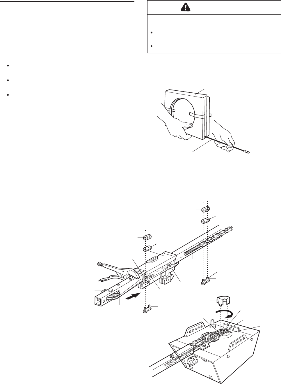
ASSEMBLY STEP 4
Install the Chain/Cable
and Attach the Sprocket Cover
1. Pull the cable around the idler pulley and toward
the trolley.
2. Connect the cable loop to the retaining slot on the
trolley, as shown:
From below, push pins of master link bar up
through cable loop and trolley slot.
Push master link cap over pins and past pin
notches.
Slide clip-on spring over cap and onto pin
notches until both pins are securely locked in
place.
3. With the trolley against the pliers, dispense the
remainder of the cable/chain along the rail toward
the motor unit and around the sprocket. The
sprocket teeth must engage the chain.
4. Check to make sure the chain is not twisted, then
connect it to the threaded shaft with the remaining
master link.
5. Thread the inner nut and lock washer onto the the
trolley shaft.
6. Insert the trolley threaded shaft through the hole
in the trolley. Be sure the chain is not twisted.
7. Loosely thread the outer nut onto the trolley shaft.
8. Remove the locking pliers.
9. Align the tabs on the sprocket cover with the slots
in the mounting plate. Squeeze cover and insert
tabs in slots.
WARNING
To avoid possible serious injury to fingers from moving
garage door opener:
ALWAYS keep hand clear of sprocket while operating
opener.
Securely attach sprocket cover BEFORE operating.
Dispensing Carton
Leave Chain and Cable
Inside Dispensing
Carton to Prevent Kinking
Keep Chain and Cable
Taut When Dispensing
Master Link
Clip-On Spring
Master
Link Cap
Cable
Loop
Idler
Pulley
Cable Master
Link Bar
Slotted
Hole
Round
Hole
Trolley
Threaded
Shaft
Pin
Notch
Cover Motor Unit
Front
Tab Slot Back
Tab Slot
Mounting
Plate
Master
Link Bar
Master
Link Cap
Master Link
Clip-On Spring
Sprocket
Sprocket
9
ASSEMBLY STEP 5
Tighten the Chain
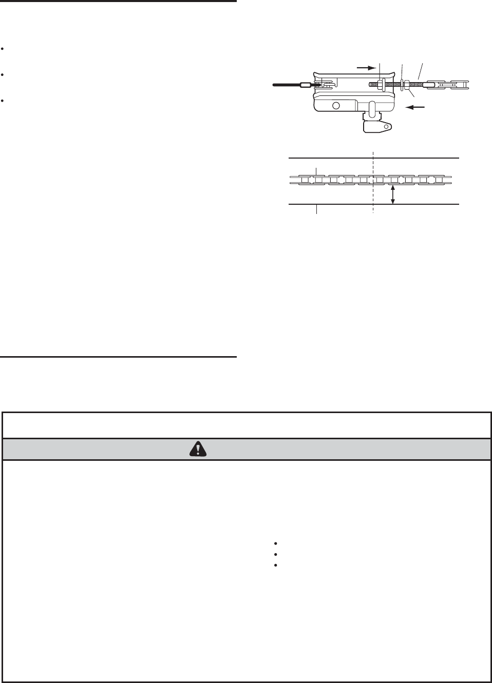
Spin the inner nut and lock washer down the
threaded shaft, away from the trolley.
To tighten the chain, turn outer nut in the direction
shown (Figure 1).
When the chain is approximately 1/2" above the
base of the rail at its midpoint, re-tighten the inner
nut to secure the adjustment.
Sprocket noise can result if chain is too loose.
When installation is complete, you may notice some
chain droop with the door closed. This is normal. If
the chain returns to the position shown in Figure 2
when the door is open, do not re-adjust the chain.
NOTE: During future maintenance, ALWAYS pull the
emergency release handle to disconnect trolley
before adjusting chain.
NOTE: You may notice loosening of chain after
Adjustment Step 2 (Test the Safety Reversal
System). Check for proper tension and readjust
chain if necessary. Then repeat Adjustment Step 2.
You have now finished assembling your garage
door opener. Please read the following warnings
before proceeding to the installation section:
INSTALLATION
WARNING
IMPORTANT INSTALLATION INSTRUCTIONS
To reduce the risk of severe injury or death:
1. READ AND FOLLOW ALL INSTALLATION WARNINGS
AND INSTRUCTIONS.
2. Install garage door opener only on properly balanced
and lubricated garage door. An improperly balanced
door may not reverse when required and could result in
severe injury or death.
3. All repairs to cables, spring assemblies and other
hardware MUST be made by a trained door systems
technician before installing opener.
4. Disable all locks and remove all ropes connected to
garage door before installing opener to avoid
entanglement.
5. Install garage door opener 7 feet or more above floor.
6. Mount emergency release handle 6 feet above floor.
7. NEVER connect garage door opener to power source
until instructed to do so.
8. NEVER wear watches, rings or loose clothing while
installing or servicing opener. They could be caught in
garage door or opener mechanisms.
9. Install wall-mounted garage door control:
within sight of the garage door
out of reach of children at minimum height of 5 feet
away from all moving parts of the door.
10. Place entrapment warning label on wall next to garage
door control.
11. Place manual release/safety reverse test label in plain
view on inside of garage door.
12. Upon completion of installation, test safety reversal
system. Door MUST reverse on contact with a one-
inch high object (or a 2x4 laid flat) on the floor.
To Tighten Outer Nut
Outer
Nut
Lock
Washer
Trolley
Shaft
Inner Nut
To Tighten
Inner Nut
Chain
Base of Rail
1/2 inch
Mid length of Rail
Figure 1
Figure 2
10
11
INSTALLATION STEP 1
Determine the Header Bracket
Location
WARNING
To prevent possible SERIOUS INJURY or DEATH:
Header bracket MUST be RIGIDLY fastened to
structural support on header wall or ceiling, otherwise
garage door might not reverse when required. DO NOT
install header bracket over drywall.
Concrete anchors MUST be used if mounting header
bracket or 2x4 into masonry.
NEVER try to loosen, move or adjust garage door,
springs, cables, pulleys, brackets, or their hardware, all
of which are under EXTREME tension.
ALWAYS call a trained door systems technician if
garage door binds, sticks, or is out of balance. An
unbalanced garage door might not reverse when
required.
Header
Wall
Vertical
Centerline
Finished
Ceiling
Stuctural
Supports
24
Vertical
Centerline
Ceiling
Header Wall
Track
Highest Point
of Travel
Door
Sectonal door
with curved
track
2"
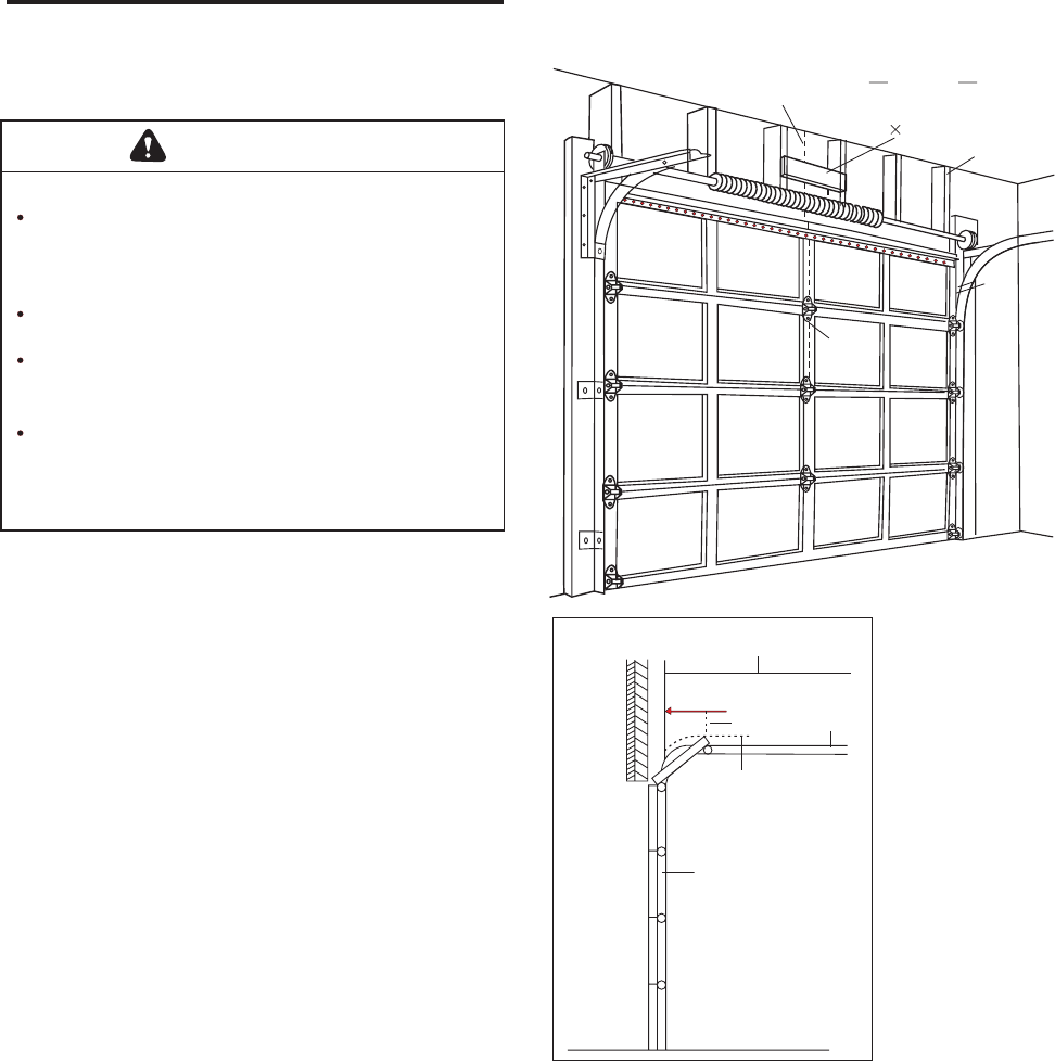
Installation procedures vary according to garage door
types. Follow the instructions which apply to your door.
1. Close the door and mark the inside vertical
centerline of the garage door.
2. Extend the line onto the header wall above the
door.
SECTIONAL DOOR
You can fasten the header bracket within 4 feet
of the left or right of the door center only if a
torsion spring or center bearing plate is in the
way; or you can attach it to the ceiling(see page
12)when clearance is minimal.(It may be mounted
on the wall upside down if necessary, to gain
approximately 1/2 inch.)
If you need to install the header bracket on a 2x4 (on
wall or ceiling), use lag screws (not provided) to securely
fasten the 2x4 to structural supports as show here.
3. Open your door to the highest point of travel as shown.
Draw an intersecting horizontal line on the header wall
2 inch above the high point. This height will provide
travel clearance for the top edge of the door.
NOTE: Door clearance brackets are available for sectional
doors when headroom clearance is less than 2 inch.
Proceed to step 2, page 12.
INSTALLATION STEP 2
Install the Header Bracket
You can attach the header bracket either to the wall
above the garage door, or to the ceiling. Follow the
instructions which will work best for your particular
requirements. Do not install the header bracket
over drywall. If installing into masonry, use
concrete anchors (not provided).
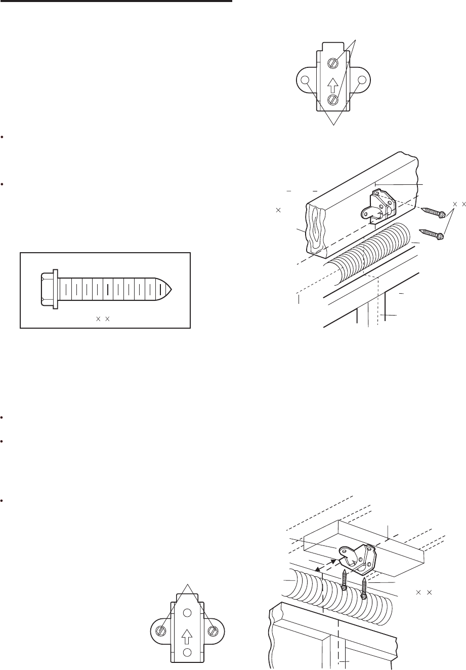
WALL HEADER BRACKET INSTALLATION
Center the bracket on the vertical centerline with
the bottom edge of the bracket on the horizontal
line as shown (with the arrow pointing toward the
ceiling).
Mark the vertical set of bracket holes. Drill 3/16"
pilot holes and fasten the bracket securely to a
structural support with the hardware provided.
CEILING HEADER BRACKET INSTALLATION
Extend the vertical centerline onto the ceiling as
shown.
Center the bracket on the vertical mark, no more
than 6" from the wall. Make sure the arrow is
pointing away from the wall. The bracket can be
mounted flush against the ceiling when clearance
is minimal.
Mark the side holes. Drill 3/16" pilot holes and
fasten bracket securely to a structural support with
the hardware provided.
UP
Wall Mount
Optional
Mounting Holes
Header
Wall
Vertical
Centerline
24
Structural
Support
Header
Bracket
Vertica
Centerline
Lag Screws
5/16" 9 1-5/8"
Door Spring
Highest Point of
Garage Door Travel
Garage
Door
Vertical Centerline
Header
Bracket
- Finished Ceiling -
Vertical
Centerline
6" Maximum
Door
Spring Lag Screws
5/16" 9 1-5/8"
-Header Wall-
Garage Door
UP
Ceiling Mounting Holes
Lag Screws
5/16" 9 1-5/8"
HAROWARE SHOWN ACTUAL SIZE
12
INSTALLATION STEP 3
Attach the Rail to the Header
Bracket
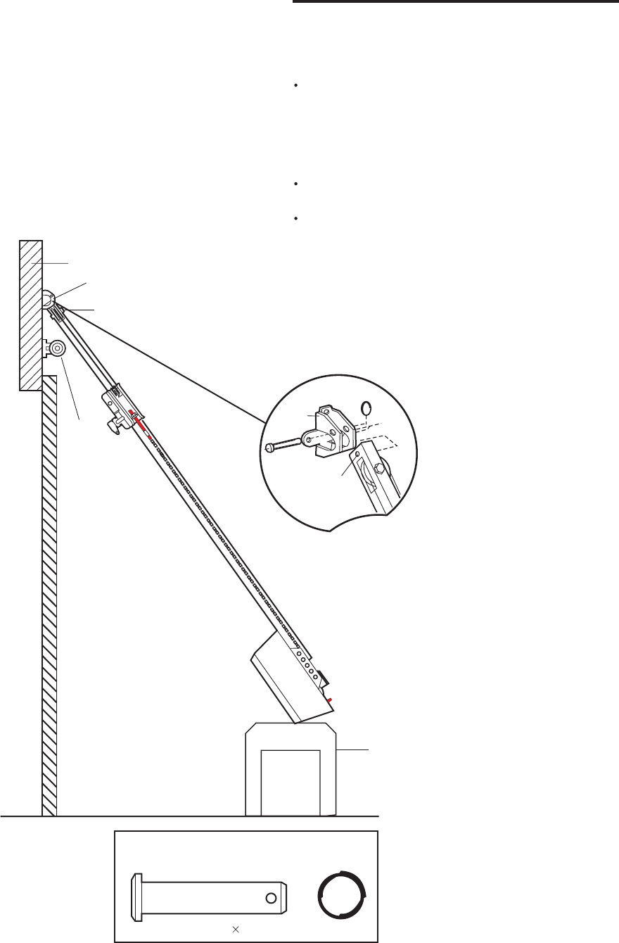
Position the opener on the garage floor below the
header bracket. Use packing material as a
protective base. NOTE: lfthe door spring is in the
way you'll need help. Have someone hold the
opener securely on a temporary support to allow
the rail to clear the spring.
Position the front rail end within the header bracket
and join with a 5/16"x1-1/2" clevis pin as shown.
Insert a ring fastener to secure.
Header Wall
Header Bracket
Idler Pulley
Torsion
Spring
Header
Bracket
Mounting
Hole
Garage Door Opener Carton or
Temporary
Support
HARDWARE SHOWN ACTUAL SIZE
Clevis Pin 5/16" 1-1/2" Ring fastener
13
INSTALLATION STEP 4
Position the Opener
Follow instructions which apply to your door type as
illustrated.
SECTIONAL DOOR
A 2x4 laid flat is convenient for setting an ideal door-
to-rail distance.
Raise the opener onto a stepladder. You will need
help at this point if the ladder is not tall enough.
Open the door all the way and place a 2x4 laid flat
on the top section beneath the rail.
If the top section or panel hits the trolley when you
raise the door, pull down on the trolley release arm
to disconnect inner and outer sections. Slide the
outer trolley toward the motor unit. The trolley can
remain disconnected until installation Step 12
is completed.
To prevent damage to garage door, rest garage door
opener rail on 2x4 placed on top section of door.
CAUTION
Outer Trolley Inner Trolley
Door 24
ENGAGED
Trolley
Release Arm
RELEASED
14
15
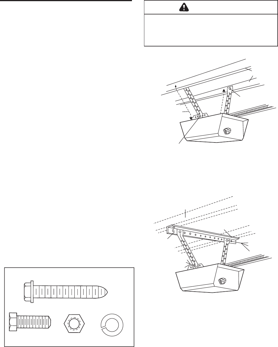
INSTALLATION STEP 5
Hang the Opener
Two representative installations are shown. Yours
may be different. Hanging brackets should be angled
(Figure 1) to provide rigid support. On finished
ceilings (Figure 2), attach a sturdy metal bracket to
structural supports before installing the opener. This
bracket and fastening hardware are not provided.
1. Measure the distance from each side of the motor
unit to the structural support.
2. Cut both pieces of the hanging bracket to required
lengths.
3. Drill 3/16" pilot holes in the structural supports.
4. Attach one end of each bracket to a support with
5/16"-18x1-7/8" lag screws.
5. Fasten the opener to the hanging brackets with
5/16"-18x7/8" hex screws, lock washers and nuts.
6. Check to make sure the rail is centered over the
door (or in line with the header bracket if the
bracket is not centered above the door).
7. Remove the 2x4. Operate the door manually. If
the door hits the rail, raise the header bracket.
NOTE: Do NOT connect power to opener at this
time.
To avoid possible SERIOUS INJURY from a falling
garage door opener, fasten it SECURELY to structural
supports of the garage. Concrete anchors MUST be used
if installing any brackets into masonry.
WARNING
HARDWARE SHOWN ACTUAL SIZE
Lock Washer 5/16"
Nut 5/16"-18
Hex Screw
5/16"-18x7/8"
Lag Screw
5/16"-18x1-7/8"
Structural
Supports
Lag Screws
5/16"-18x1-7/8"
5/16"-18x1-7/8" Screw
5/16" Lock Washer
5/16" -18 Nut
Measure
Distance
Figure 1
Figure 2
Hidden
Support
Lag Screws
5/16"-18x1-7/8"
Bracket
(Not Provided)
5/16"-18x7/8" Screw
5/16" Lock Washer
5/16"-18 Nut
5/16" Lock Washer
5/16"-18x7/8" Screw
5/16"-18 Nut
(Not Provided)
F inished Ceiling
-Finished Ceiling-
16
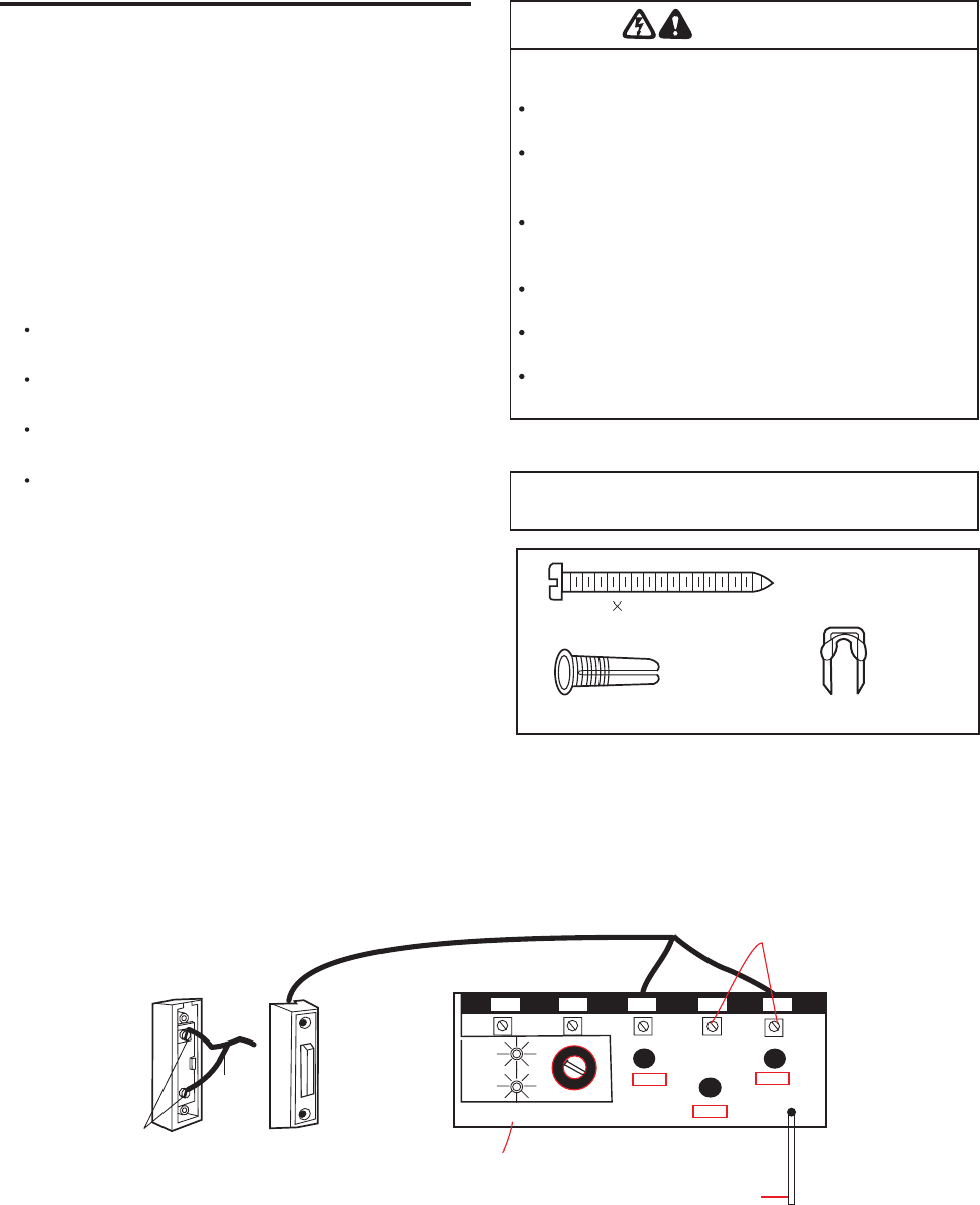
INSTALLATION STEP 6
Install the Door Control
Locate door control within sight of door, at a minimum
height of 5 feet where small children cannot reach,
away from moving parts of door and door hardware.
If installing into drywall, drill 5/32" holes and use the
anchors provided.
1. Strip 1/4" of insulation from one end of bell wire and
connect to the two terminal screws on back of door
control by color: white to 2 and white/red to 1.
2. Fasten securely withDoor Control Button:
6ABx 1-1/2" screws.
Install bottom screw, allowing 1/8" to protrude
above wall surface.
Position bottom of door control on screw head and
slide down to secure. Adjust screw for snug fit.
Drill and install top screw with care to avoid
cracking plastic housing. Do not over tighten.
Insert top tabs and snap on cover.
3. Run bell wire up(For standard installation only)
wall and across ceiling to motor unit. Use insulated
staples to secure wire in several places. Be careful
not to pierce wire with a staple, creating a short or
open circuit.
4. Connect the bell wire to the terminal screws on the
motor unit panel: white to 5; white/red to 3.
5. Position the antenna wire as shown.
6. Use tacks or staples to permanently attach
entrapment warning label to wall near door control,
and manual release/safety reverse test label in a
prominent location on inside of garage door.
DO NOT connect power and operate opener at
this time. The trolley will travel to the full open
position but will not return to the close position
until the sensor beam is connected and properly
aligned.
WARNING
To prevent possible SERIOUS INJURY or DEATH from
electrocution:
Be sure power is not connected BEFORE installing door
control.
Connect ONLY to 24 VOLT low voltage wires.
To prevent possible SERIOUS INJURY or DEATH from a
closing garage door:
Install door control within sight of garage door, out of
reach of children at a minimum height of 5 feet, and away
from all moving parts of door.
NEVER permit children to operate or play with door control
push buttons or remote control transmitters,
Activate door ONLY when it can be seen clearly, is properly
adjusted, and there are no obstructions to door travel.
ALWAYS keep garage door in sight until completely closed.
NEVER permit anyone to cross path of closing garage door.
Outside Keylock Accessory Connections
To opener terminal screws: white to 4; white/red to 3
6AB 1-1/2" Screw
Door Control Button
HARDWARE SHOWN
ACTUAL SIZE
Insulated
Staples
Dry Wall Anchors
Terminal
Screws
Bell
Wire
(BACK VIEW)
DOOR CONTROL BUTTON
WHT
2
RED
1
12345
WORK
SHIFT
YAKO
Antenna
Back Panel
of Opener
Opener Terminal Screws
17
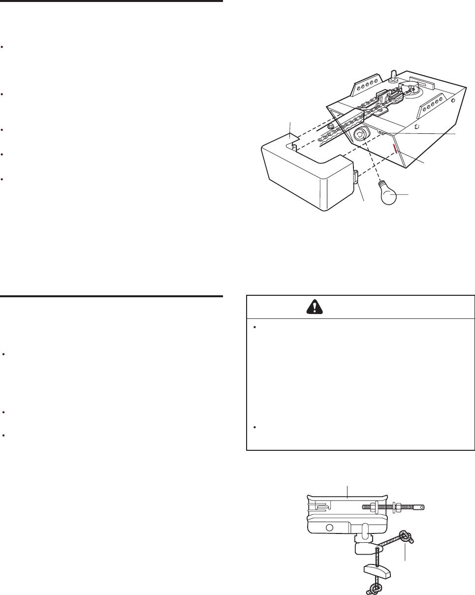
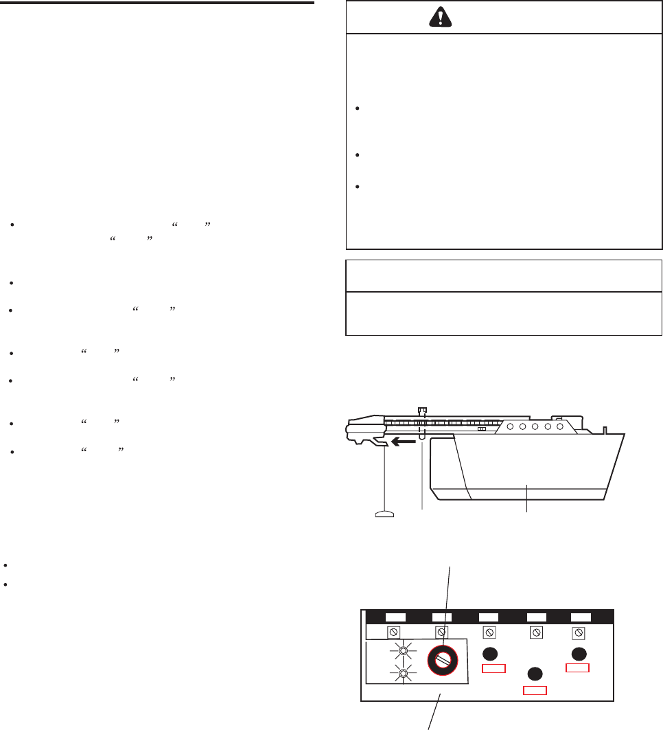
INSTALLATION STEP 7
Install the Light and Lens
Install a 75 watt maximum light bulb in the socket.
The light will turn ON and remain lit for
approximately 4-1/2 minutes when power is
connected. Then the light will turn OFF.
Apply slight pressure on the sides of the lens and
slide the tabs into the slots in the end panel. (See
illustration.)
For convenience, the lens may be installed
after Adjustment Step on page
To remove, reverse the procedure. Use care to
avoid snapping off lens tabs.
Use standard neck Garage Door Opener bulbs for
replacement.
INSTALLATION STEP 8
Attach the Emergency Release
Rope and Handle
Thread one end of the rope through the hole in the
top of the red handle so "NOTICE" reads right side
up as shown. Secure with an overhand knot at
least 1" from the end of the rope to prevent
slipping.
Thread the other end of the rope through the hole
in the release arm of the outer trolley.
Adjust rope length so the handle is 6 feet above
the floor. Secure with an overhand knot.
NOTE: lf it is necessary to cut the rope, heat seal
the cut end with a match or lighter to prevent
unraveling.
WARNING
To prevent possible SERIOUS INJURY or DEATH from
a falling garage door:
If possible, use emergency release handle to
disengage trolley ONLY when garage door is
CLOSED. Weak or broken springs or unbalanced
door could result in an open door falling rapidly
and/or unexpectedly.
NEVER use emergency release handle unless garage
doorway is clear of persons and obstructions.
NEVER use handle to pull door open or closed. If rope
knot becomes untied, you could fall.
_
_
Light
Lens
Lens
Tab
Lens
Guide
75 Watt Max.
Light Bulb
Lens
Slot
Trolley
Trolley
Release am
Emergency
Release Handle
Overhand
Knot
Nikota
325 .
INSTALLATION STEP 9
Electrical Requirements
To avoid installation difficulties, do not run the
opener at this time.
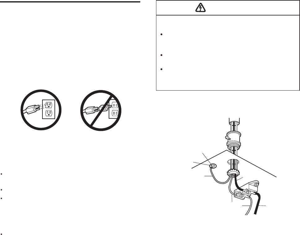
To reduce the risk of electric shock, your garage door
opener has a grounding type plug with a third
grounding pin. This plug will only fit into a grounding
type outlet. If the plug doesn't fit into the outlet you
have, contact a qualified electrician to install the
proper outlet.
If permanent wiring is required by your local
code, refer to the following procedure.
To make a permanent connection through the 7/8"
hole in the top of the motor unit:
Remove the motor unit cover screws and set the
cover aside.
Remove the attached 3-prong cord.
Connect the black (line) wire to the screw on the
brass terminal; the white (neutral) wire to the
screw on the silver terminal; and the ground wire
to the green ground screw. The opener must be
Reinstall the cover.
grounded.
Be sure power is not connected to the opener, and
disconnect power to circuit BEFORE removing cover to
establish permanent wiring connection.
Garage door installation and wiring MUST be in
compliance with all local electrical and building codes.
NEVER use an extension cord, 2-wire adapter, or
change plug in any way to make it fit outlet. Be sure
the opener is grounded.
To prevent possible SERIOUS INJURY or DEATH from
electrocution or fire:
WARNING
PERMANENT WIRING
CONNECTION
Ground Tab
Green
Ground Screw
Ground Wire
Black
Wire
White Wire Black Wire
RIGHT WRONG
18
INSTALLATION STEP 10
Install The Safety Reversing Sensor
The safety reversing sensor must be connected
and aligned correctly before the garage door
opener will move in the down direction.
IMPORTANT INFORMATION ABOUT
THE SAFETY REVERSING SENSOR
When properly connected and aligned, the sensor
will detect an obstacle in the path of its electronic
beam. The sending eye (with an green indicator
light) transmits an invisible light beam to the
receiving eye (with a green indicator light). If an
obstruction breaks the light beam while the door is
closing, the door will stop and reverse to full open
position, and the opener lights will flash 10 times.
The units must be installed inside the garage so that
the sending and receiving eyes face each other
across the door, no higher than 6" above the floor.
Either can be installed on the left or right of the door
as long as the sun never shines directly into the
receiving eye lens.
The mounting brackets are designed to clip onto the
track of sectional garage doors without additional
hardware.
WARNING
Be sure power is not connected to the garage door
opener BEFORE installing the safety reversing sensor.
To prevent SERIOUS INJURY or DEATH from a closing
garage door:
-
-
Correctly connect and align the safety reversing
sensor. This required safety device MUST NOT be
disabled.
Install the safety reversing sensor so beam is NO
HIGHER than 6" above garage floor.
If it is necessary to mount the units on the wall, the
brackets must be securely fastened to a solid
surface such as the wall framing. If installing in
masonry construction, add a piece of wood at each
location to avoid drilling extra holes in masonry if
repositioning is necessary.
The invisible light beam path must be unobstructed.
No part of the garage door (or door tracks, springs,
hinges, rollers or other hardware) may interrupt the
beam while the door is closing.
Sensor Beam
6" maximum
above floor
Invisible Light Beam
Protection Area
Facing the door from inside the garage
Sensor Beam
6" maximum
above floor
19
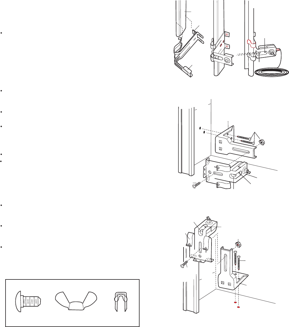
INSTALLING THE BRACKETS
Be sure power to the opener is disconnected.
Install and align the brackets so the sensors will face
each other across the garage door, with the beam no
higher than 6" above the floor. They may be installed
in one of three ways, as follows.
Garage door track installation (preferred):
Slip the curved arms over the rounded edge of
each door track, with the curved arms facing the
door. Snap into place against the side of the track.
It should lie flush, with the lip hugging the back
edge of the track, as shown in Figure 1.
If your door track will not support the bracket
securely, wall installation is recommended.
Wall installation:
Place the bracket against the wall with curved arms
facing the door. Be sure there is enough clearance
for the sensor beam to be unobstructed.
If additional depth is needed, an extension bracket
(not provided) or wood blocks can be used.
Use bracket mounting holes as a template to locate
and drill (2) 3/16" diameter pilot holes on the wall at
each side of the door, no higher than 6" above the
floor.
Attach brackets to wall with lag screws (not provided).
If using extension brackets or wood blocks, adjust
right and left assemblies to the same distance out
from the mounting surface. Make sure all door
hardware obstructions are cleared.
Floor installation:
Use wood blocks or extension brackets (
) to elevate sensor brackets so the
lenses will be no higher than 6" above the floor.
not
provided
Carefully measure and place right and left
assemblies at the same distance out from the wall.
Be sure all door hardware obstructions are cleared.
Fasten to the floor with concrete anchors as shown.
HARDWARE SHOWN ACTUAL SIZE
Carriage Bolt
1/4"-20x1/2"
Wing Nut
1/4"-20
Staples
Indicator
Light
Lens
Figure 1
DOOR TRACK MOUNT(RIGHT SIDE)
Door
Track
Lip
Sensor
Bracket
Figure 2
WALL MOUNT(RIGHT SIDE)
Inside
Garage
Wall
Extension
Bracket
(not provided)
(not Provided)
(not Provided ) Sensor
Bracket
Indicator
Light
Lens
Figure 3
FLOOR MOUNT(RIGHT SIDE)
Extension
Bracket
(not provided)
(not Provided )
(not Provided)
Sensor
Bracket
Indicator
Light
Lens
Attach with
Concrete Anchors
(not provided)
Inside
Garage
Wall
20
21
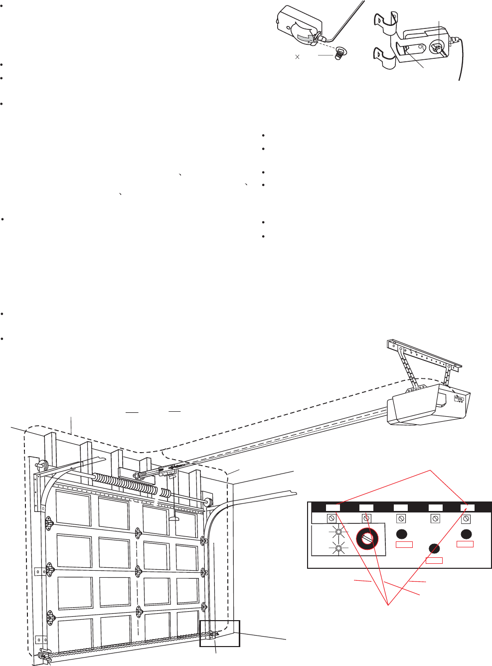
MOUNTING AND WIRING THE SAFETY SENSORS
Slide a 1/4"-20x1/2" carriage bolt head into the slot
on each sensor. Use wing nuts to fasten sensors to
brackets, with lenses pointing toward each other
across the door. Be sure the lens is not obstructed
by a bracket extension. See Figure 4.
Finger tighten the wing nuts.
Run the wires from both sensors to the opener. Use
insulated staples to secure wire to wall and ceiling.
Strip 1/4" of insulation from each set of wires.
Separate wires sufficiently to connect to the opener
terminal screws: The Sensor Emitter white to 5
and white with fine black dashdotted to 1;the Sensor
Receiver white to 5 and white/thick black dashdotted
to 2 and white/black dot to 1..
's
's
ALIGNING THE SAFETY SENSORS
Plug in the opener. The indicator lights in both the
sending and receiving eyes will glow steadily if
wiring connections and alignment are correct.
The sending eye green indicator light will glow
regardless of alignment or obstruction. If the green
indicator light in the receiving eye is off, dim, or
flickering (and the invisible light beam path is not
obstructed), alignment is required.
Loosen the sending eye wing nut and readjust,
aiming directly at the receiving eye. Lock in place.
Loosen the receiving eye wing nut and adjust
sensor until it receives the sender's beam. When
the green indicator light glows steadily, tighten the
wing nut.
TROUBLESHOOTING THE SAFETY SENSORS
1. If the indicator light does not
after installation, check for:
sending eye glow
steadily
Electric power to the opener.
A short in the wires. These can occur at staples,
or at screw terminal connections.
Incorrect wiring between sensors and opener.
A broken wire.
2. If the sending eye indicator light glows steadily but
the receiving eye indicator light doesn't:
Check alignment.
Check for an open wire to the receiving eye.
3. If the receiving eye indicator light is dim, realign
either sensor.
NOTE: When the invisible beam path is obstructed
or misaligned while the door is closing, the door will
reverse. If the door is already open, it will not close.
The opener lights will flash 10 times. See page 19.
Figure 5
Bell wire Finished
Ceiling
Connect Wire to
Opener Terminals
OPENER TERMINAL SCREWS
Sensor Emitter
Invisible Light Beam
Protection Area
Sensor
Bell wire
1/4" -20 1/2"
Carriage bolt
Wing nut
Lens
Figure 4
NOTE: The Sensor Emitter had 2 wire (white white with fine
black dashdotted) and the Sensor Receiver had 3 wire(white
white/thick black dashdotted white/black dot)
Sensor Receiver
12345
WORK
SHIFT
YAKO
White
White with fine
black dashdotted
Sensor Emitter Connections
White
White/thick black
dashdotted
White/black dot
Sensor Receiver Connections
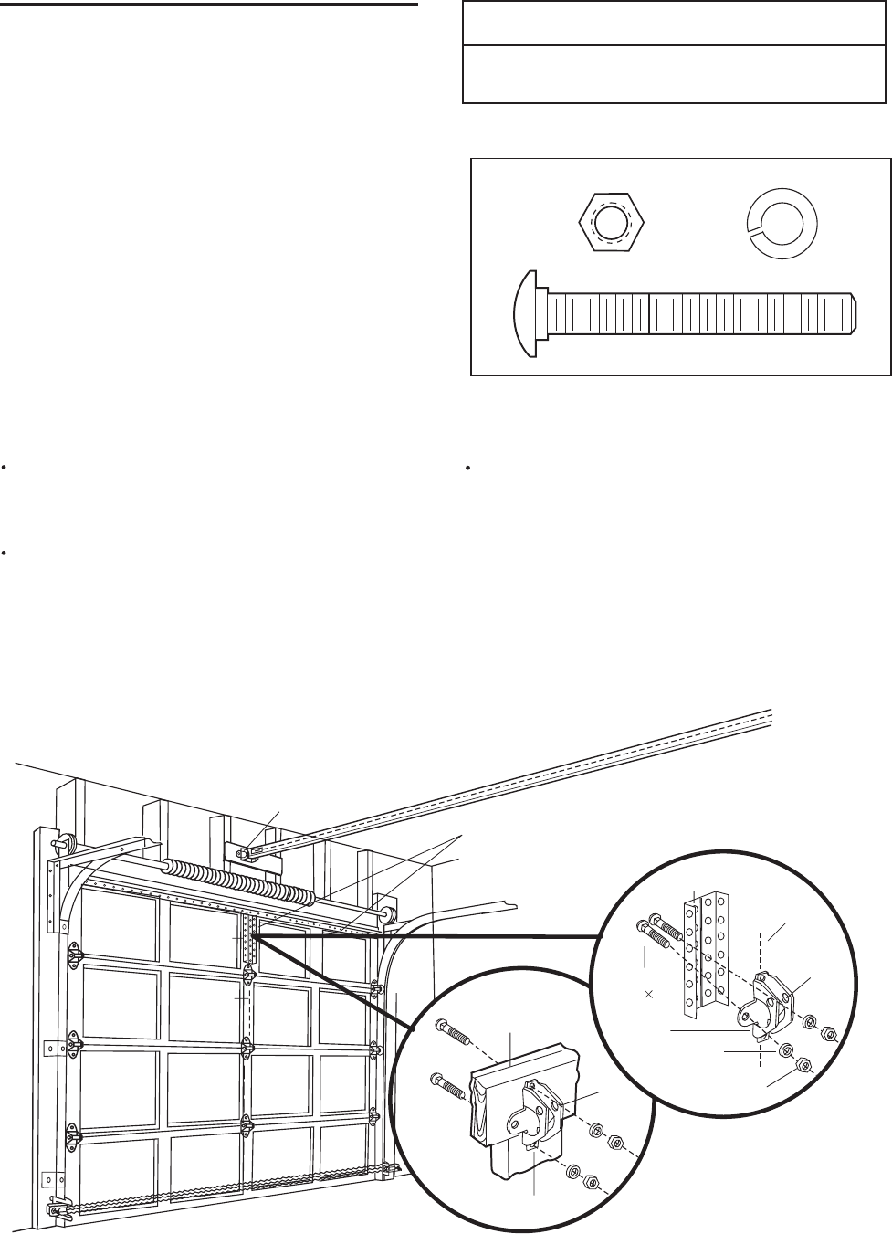
INSTALLATION STEP 11
Fasten the Door Bracket
Follow instructions which apply to your door type
as illustrated below or on the following page.
A horizontal reinforcement brace should be long
enough to be secured to two vertical supports. A
vertical reinforcement brace should cover the
height of the top panel.
The illustration shows one piece of angle iron as the
horizontal brace. For the vertical brace, two pieces of
angle iron are used to create a "U''-shaped support
(Figure 1). The best solution is to check with your
garage door manufacturer for an opener installation
door reinforcement kit.
NOTE: Many vertical brace installations provide for
direct attachment of the clevis pin and door arm. In
this case you will not need the door bracket; proceed
to Installation Step 12.
SECTIONAL DOORS
Center the door bracket on the previously marked
vertical centerline used for the header bracket
installation. Note correct UP placement, as
stamped inside the bracket (Figure 2).
Position the bracket on the face of the door within
the following limits:
A) The top edge of the bracket 2"-4" below the top
edge of the door.
B) The top edge of the bracket directly below any
structural support across the top of the door.
CAUTION
To prevent damage to garage door, reinforce inside of
door with angle iron both vertically and horizontally.
Mark and drill15/16" left and right fastening holes.
Secure the bracket as shown in Figure 1 if there is
vertical reinforcement.
If your installation doesn't require vertical reinforce-
ment but does need top and bottom fastening holes
for the door bracket, fasten as shown in Figure 2.
Horizontal and vertical reinforcement
is needed for lightweight garage doors
(fiberglass, aluminum, steel, doors with
glass panel, etc). (Not Provided)
Header Bracket
Door
Bracket
Location
Vertical
Centerine
Inside Edge
of Door or
Reinforcement Board
UP
Door Bracket
Vertical
Reinforcement
Vertical
Centerline
Carriage Bolt
5/16"-18 2-1/2"
Door
Bracket
Lock Washer
5/16" Nut
5/16"-18
UP
Figure 1
Figure 2
Carriage Bolt
HARDWARE SHOWN ACTUAL SIZE
Lock Washer 5/16"
Nut 5/16"-18
5/16"-18x2-1/2"
22
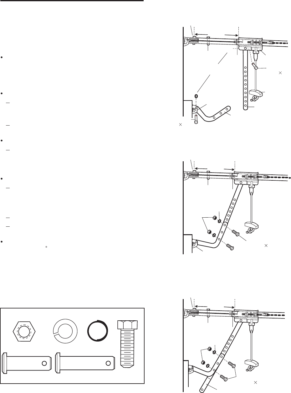
INSTALLATION STEP 12
Connect Door Arm to Trolley
Follow instructions which apply to your door type as
illustrated below and on the following page.
SECTIONAL DOORS ONLY
Make sure garage door is fully closed. Pull the
emergency release handle to disconnect the outer
trolley from the inner trolley. Slide the outer trolley
back (away from the pulley) for 8" minimum as
shown in Figures 1, 2 and 3.
Figure 1:
Fasten straight door arm section to outer trolley
with the 5/16"x1" clevis pin. Secure the
connection with a ring fastener.
Fasten curved section to the door bracket in the
same way, using the 5/16"x1-1/4" clevis pin.
Figure 2:
Bring arm sections together. Find two pairs of
holes that line up and join sections. Select holes
as far apart as possible to increase door arm
rigidity.
Figure 3, Hole alignment alternative:
If holes in curved arm are above holes in straight
arm, disconnect straight arm. Cut about 6" from
the solid end. Reconnect to trolley with cut end
down as shown.
Bring arm sections together.
Find two pairs of holes that line up and join with
screws, lock washers and nuts.
Pull the emergency release handle toward the
opener at a 45 angle so that the trolley release
arm is horizontal. Proceed to Adjustment Step 1,
page 24. Trolley will re-engage automatically when
opener is operated.
8" MIN
0
Pulley
Trolley
Stop Bolt
Ring
Fastener
Door
Bracket
Outer
Trolley
Clevis Pin
5/16" 1"
Emergency
Release
Handle
Straight
Door Arm
Curved Door Arm
Clevis Pin
5/16" 1-1/4"
Inner
Trolley
Figure 1
8" MIN
Pulley
Trolley
Stop Bolt
Figure 2
Nuts
5/16"-18
Lock
Washers
5/16"
Door Bracket
Screws
5/16"-18 7/8"
8" MIN
Pulley
Trolley
Stop Bolt
Figure 3
Nuts
5/16"-18
Lock
Washers
5/16"
Screws
5/16"-18 7/8"
Cut this end
HARDWARE SHOWN ACTUAL SIZE
Lock Washer 5/16"
Nut 5/16"-18
Hex Screw
5/16"-18x7/8"
Clevis Pin
5/16"x1" (Trolley)
Clevis Pin
5/16"x1-1/4" (Door Bracket)
Ring fastener
23
24
ADJUSTMENT STEP 1
Adjust limits and force
Limit adjustment settings regulate the points at which
the door will stop when moving up or down.
To operate the opener, press the Door Control push
button. Run the opener through a complete travel
cycle.
Does the door open and close completely?
Does the door stay closed and not reverse
unintentionally when fully closed?
NOTE: Repeated operation of the opener during
adjustment procedures may cause the motor to
overheat and shut off. Simply wait 15 minutes and
try again.
NOTE: If anything interferes with the door's upward
travel, it will stop. lf anything interferes with the
door's downward travel (including binding or
unbalanced doors), it will reverse.
CAUTION
WARNING
Without a properly installed safety reversal system,
persons (particularly small children) could be
SERIOUSLY INJURED or KILLED by a closing garage
door.
Incorrect adjustment of garage door travel limits will
interfere with proper operation of safety reversal
system.
If one control (force or travel limits) is adjusted, the
other control may also need adjustment.
After any adjustments are made, the safety reversal
system MUST be tested. Door MUST reverse on
contact with one-inch high object (or 2x4 laid flat) on
floor.
To prevent damage to vehicles, be sure fully open door
provides adequate clearance.
2-4"
Cover
Protection
Bolt
Left Side Panel
Force adjustment settings regulate the amount of
power required to open and close the door. If the
force are set too light, door travel may be interrupted
by nuisance reversals in the down direction and stops
in the up direction. Weather conditions can affect the
door movement, so occasional adjustment may be
needed.
1.Adjust limit and force:
Press and hold down the shift push button,
then press the work push button. Hold down
both push buttons simultaneosuly until LED(green)
flashes quickly. Release both push buttons.
Wait a short moment until LED(red) and LED(green)
flash finish simultaneously.
Press and hold the work push button and move
the door until the door is fully closed. LED(green)
light up.
Press the shift push button. The door DOWN
travel limits position is stored, LED(red) light up.
Press and hold the work push button and move
the door until the door is fully opened. LED(green)
light up.
Press the shift push button. The door OPEN
travel limits position is stored, LED(red) light up.
Press the work push button brevity. LED(red)
and LED(green) flash. With a time delay the door
close fully x 1and opens fully x 1. The lights go
out. LED(red) flashes. Programming is complete.
NOTE: To prevent the trolley from hitting the cover
Protection bolt, keep a minimum distance of 2-4"
Between the trolley and the bolt.
12345
WORK
SHIFT
YAKO
Tractive Force Adjustment Control
Back Panel
2. Setting tractive force:
Force adjustment controls are located on the back panel of the motor unit, the tractive force is set by a
small screwdriver on the control, it must be set to that a counter-pressure of 150N(approx.15kg) leads
to a reversal of the closing door and a stop of the opening door. The counter-pressure may be simulated
by simulated by pressing ones hand lightly against the closing garage door.
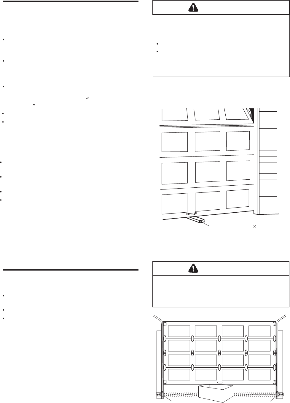
ADJUSTMENT STEP 2
Test the Safety Reversal System
TEST
With the door fully open, place a one-inch board
(or a 2x4 laid flat) on the floor, centered under the
garage door.
Operate the door in the down direction. The door
must reverse on striking the obstruction.
ADJUST
If the door stops on the obstruction, it is not
traveling far enough in the down direction.
Remove the board, repeat the Adjust limit
and force Step.
Repeat the test.
When the door reverses on the one-inch board,
remove the obstruction and run the opener through
3 or 4 complete travel cycles to test adjustment.
IMPORTANT SAFETY CHECK:
Repeat Adjustment Steps 1, 2 and 3 after:
Each adjustment of door arm length, limits, or
force controls.
Any repair to or adjustment of the garage door
(including springs and hardware).
Any repair to or buckling of the garage floor.
Any repair to or adjustment of the opener.
ADJUSTMENT STEP 3
Test the Safety Reversing Sensor
Press the remote control push button to open the
door.
Place the opener carton in the path of the door.
Press the remote control push button to close the
door. The door will not move more than an inch,
and the opener light will flash.
The garage door opener will not close from a remote
if the indicator light in either sensor is off (alerting
you to the fact that the sensor is misaligned or
obstructed).
If the opener closes the door when the safety
reversing sensor is obstructed (and the sensors
are no more than 6" above the floor), call for a
trained door systems technician.
WARNING
Without a properly installed safety reversal system,
persons (particularly small children) could be
SERIOUSLY INJURED or KILLED by a closing garage
door.
Safety reversal system MUST be tested every month.
After ANY adjustments are made, the safety reversal
system MUST be tested. Door MUST reverse on
contact with one-inch high object (or 2x4 laid flat) on
the floor.
WARNING
Without a properly installed safety reversing sensor,
persons (particularly small children) could be
SERIOUSLY INJURED or KILLED by a closing garage
door.
One-inch board (or a 2 4 laid flat)
Safety Reversing Sensor Safety Reversing Sensor
25
OPERATION
IMPORTANT SAFETY INSTRUCTIONS
WARNING
To reduce the risk of severe iniury or death:
1. READ AND FOLLOW ALL WARNINGS AND INSTRUCTIONS.
2. ALWAYS keep remote controls out of reach of children.
NEVER permit children to operate or play with garage
door control push buttons or remote controls.
3. ONLY activate garage door when it can be seen clearly, it
is properly adjusted, and there are no obstructions to
door travel.
4. ALWAYS keep garage door in sight until completely
closed. NO ONE SHOULD CROSS THE PATH OF THE
MOVING DOOR.
5. If possible, use emergency release handle to disengage
trolley ONLY when garage door is CLOSED. Weak or
broken springs or unbalanced door could result in an
open door falling rapidly and/or unexpectedly.
6. NEVER use emergency release handle unless garage
doorway is clear of persons and obstructions.
7. NEVER use handle to pull garage door open or closed. If
rope knot becomes untied, you could fall.
8. After any adjustments are made, the safety reversal
system MUST be tested.
9. Safety reversal system MUST be tested every month.
Garage door MUST reverse on contact with one-inch
high object (or a 2x4 laid flat) on the floor.
10. ALWAYS KEEP GARAGE DOOR PROPERLY BALANCED
(see page 3). An improperly balanced door may not
reverse when required and could result in severe injury
or death.
11. All repairs to cables, spring assemblies and other
hardware, all of which are under EXTREME tension,
MUST be made by a trained door systems technician.
12. ALWAYS disconnect electric power to garage door
opener before making any repairs or removing covers.
13.
SAVE THESE INSTRUCTIONS.
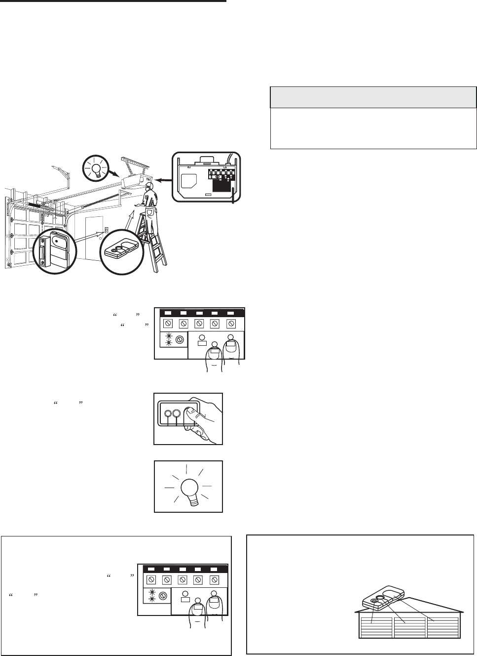
Using Your Garage Door Opener
Your opener and hand-held remote control have been
factory-set to a matching code to operate with the
large push button. Your opener will operate with as
many as four "SRT" (Smart Receiver/Transmitter)
hand-held remote controls , However, you can use
either of the two small buttons, if you prefer. And, the
3-function remote control can also activate additional
a new remote, or if you wish to deactivate any remote,
follow the instructions in the Programming section.
garage door openers and/or light controls. If you purchase
Activate your opener with any of the following:
The hand-held Remote Control: Hold the large
push button down until the door starts to move.
The wall-mounted Door Control: Hold the push
button down until the door starts to move.
When the opener is activated (with the safety
reversing sensor correctly installed and aligned)
1. If open, the door will close. If closed, it will open.
2. If closing, the door will reverse.
3. If opening, the door will stop.
4. If the door has been stopped in a partially open
position, it will close.
5. If obstructed while closing, the door wilt reverse. If
the obstruction interrupts the sensor beam, the
opener light will blink for five seconds.
6. If obstructed while opening, the door will stop.
7. If fully open, the door will not close when the beam
is broken. The sensor has no effect in the opening
cycle.
If the sensor is not installed, or is misaligned, the
door won't close from a hand-held remote. However,
you can close the door with the Door Control,
If you
release them too soon, the door will reverse.
if you
activate them until down travel is complete.
The opener light will turn on under the following
conditions: when the opener is initially plugged in;
when power is restored after interruption; when the
opener is activated.
It will turn off automatically after 4-1/2 minutes .
Bulb size is 75 watts maximum.
26
27
Using the Wall-Mounted Door Control
Press the lighted push
button to open or close the
door. Press again to reverse
the door during the closing
cycle or to stop the door
white it's opening.
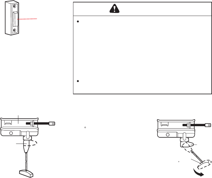
To Open the Door Manually
WARNING
To prevent possible SERIOUS INJURY or DEATH from
a falling garage door:
If possible, use emergency release handle to
disengage trolley ONLY when garage door is
CLOSED. Weak or broken springs or unbalanced
door could result in an open door falling rapidly
and/or unexpectedly.
NEVER use emergency release handle unless garage
doorway is clear of persons and obstructions.
NEVER use handle to pull door open or closed. If rope
knot becomes untied, you could fall.
-
-
DISCONNECT THE TROLLEY:
The door should be fully closed
if possible. Pull down on the
emergency release handle (so
that the trolley release arm
snaps into a vertical position)
and lift the door manually. The
prevents the
trolley from reconnecting
automatically, and the door can
be raised and lowered manually
as often as necessary.
lockout feature
TO RE-CONNECT THE TROLLEY:
Pull the emergency release
handle toward the opener at
a 45 degree angle so that
the trolley release arm is
horizontal. The trolley will
reconnect on the next UP or
DOWN operation, either
manually or by using the
door control or remote.
LIGHTED
PUSH BUTTON
Trolley
Release arm
(In Manual
Disconnect
Position)
NOTICE
Lockout position
(Manual disconnect)
Trolley
NOTICE
NOTICE
Trolley
Release
Arm
Emergency
Release Handle
(Pull at 45 angle)
To reconnect
28
Care of Your Opener
LIMIT AND FORCE ADJUSTMENTS:
Weather conditions may
cause some minor
changes in door
operation requiring some
re-adjustments,
particularly during the
first year of operation.
Pages 24 refer to
the limit and force
adjustments.
Follow the instructions carefully.
Repeat the safety reverse test (page 25) after any
adjustment of limits or force.
MAINTENANCE SCHEDULE
Once a Month
Manually operate door. If it is unbalanced or
binding, call a trained door systems technician.
Check to be sure door opens & closes fully. Adjust
limits and/or force if necessary. (See pages 24.)
Repeat the safety reverse test. Make any
necessary adjustments. (See Adjustment Step 2.)
Twice a Year
Check chain tension. Disconnect trolley first. Adjust
if necessary (See page 10).
Once a Year
Oil door rollers, bearings and hinges. The opener
does not require additional lubrication. Do not
grease the door tracks.
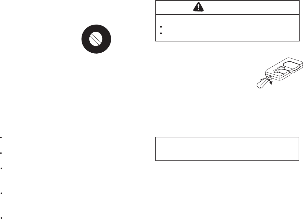
WARNING
THE REMOTE CONTROL BATTERY
To prevent possible SERIOUS INJURY or DEATH:
NEVER allow small children near batteries.
If battery swallowed, immediately notify doctor.
The lithium battery should
produce power for up to
5 years. To replace battery,
use the visor clip or
screwdriver blade to pry open
the case as shown. Insert
battery positive side down.
Dispose of old battery
properly.
NOTICE: To comply with FCC and/or Industry Canada rules , adjustment or
modifications of this receiver and/or transmitter are prohibited, except for changing
the code setting or replacing the battery. THERE ARE NO OTHER USER
SERVICEABLE PARTS.
FORCE CONTROLS
3-FUNCTION
Open this end
first to avoid
cracking
housing

Having a Problem?
1. The opener doesn't operate from either the Door
Control or the remote control:
Does the opener have electric power? Plug a lamp into the
outlet. If it doesn't light, check the fuse box or the circuit
breaker. (Some outlets are controlled by a wall switch.)
Have you disabled all door locks? Review installation
instruction warnings on page 10.
Is there a build-up of ice or snow under the door? The door
may be frozen to the ground. Remove any restriction.
The garage door spring may be broken. Have it replaced.
Repeated operation may have tripped the overload
protector in the motor. Wait 15 minutes and try again.
2. Opener operates from the remote, but not from the
Door Control:
Is the door control lit? If not, remove the bell wire from the
motor unit terminals. Short the red and white terminals by
touching both terminals at the same time with a piece of
wire. If the opener runs, check for a faulty wire connection
at the door control, a short under the staples, or a broken
wire.
Are the wiring connections correct? Review
page 16.
Installation
Step 6,
3. The door operates from the Door Control, but not from
the remote control:
Is the door push button flashing?
Program the opener to match the remote control code.
(Refer to instructions on the motor unit panel.) Repeat with
all remotes.
4. The remote control has short range:
Change the location of the remote control in your car.
Check to be sure the antenna on the side or back panel of
motor unit extends fully downward.
Some installations may have shorter range due to a metal
door, foil backed insulation, or metal garage siding.
5. The garage door opens and closes by itself:
Be sure that all remote control push buttons are off.
Remove the bell wire from the door control terminals and
operate from the remote only. If this solves the problem, the
door control is faulty (replace), or there is an intermittent short
on the wire between the door control and the motor unit.
Clear memory and re-program all remote controls.
6. The door doesn't open completely:
Is something obstructing the door? Is it out of balance, or
are the springs broken? Remove the obstruction or repair
the door.
If the door is in good working order but now doesn't open
all the way, increase the up force. See 1Adjustment Step .
If the door opens at least 5 feet, the travel limits may need
to be increased. One turn equals 2 inches of travel. See
Adjustment Step 1.
Repeat the safety reverse test after the adjustment is
complete.
7. The door stops but doesn't close completely:
Review the Adjustment Step1.
Repeat the safety reverse test after any adjustment of door
arm length, close force or down limit.
8. The door opens but won't close:
If the opener light blinks, check the safety reversing sensor.
See Installation Step 10.
If the opener light doesn't blink and it is a new installation,
check the down force. See Adjustment Step 1, page 24.
For an existing installation, see below.
Repeat the safety reverse test after the adjustment is complete.
9. The door reverses for no apparent reason and opener
light doesn't blink:
Is something obstructing the door? Pull the emergency
release handle. Operate the door manually. If it is unbalanced
or binding, call a trained door systems technician.
Clear any ice or snow from the garage floor area where
the door closes.
Review Adjustment Step 1 on page 24.
If door reverses in the fully closed position, see Adjustment
Step 1.
Repeat safety reverse test after adjustments to force and travel
limits. The need for occasional adjustment of the force and
limit settings is normal. Weather conditions in particular can
affect door travel.
10. The door reverses for no apparent reason and opener
light blinks for 5 seconds after reversing:
Check the safety reversing sensor. Remove any obstruction
or align the receiving eye. See Installation Step 10.
11, The opener light doesn't turn on:
Replace the light bulb (75 watts maximum). Use a standard
neck garage door opener bulb if regular bulb burns out.
12. The opener strains or maximum force is needed to
operate door:
The door may be out of balance or the springs may be
broken. Close the door and use the emergency release
handle to disconnect the trolley. Open and close the door
manually. A properly balanced door will stay in any point of
travel while being supported entirely by its springs. If it
does not, disconnect the opener and call a trained door
systems technician. Do not increase the force to operate
the opener.
13. The opener motor hums briefly, then won't work:
The garage door springs may be broken. See above.
If the problem occurs on the first operation of the opener,
door may be locked. Disable the door lock. If the chain was
removed and reinstalled, the motor may be out of phase.
Remove the chain; cycle the motor to the down position.
Observe the drive sprocket. When it turns in a clockwise
direction and stops in the down position, reinstall the chain.
Repeat the safety reverse test after the adjustment is
complete.
14. The opener won't operate due to power failure:
Use the emergency release handle to disconnect the
trolley. The door can be opened and closed manually.
When power is restored, press the Door Control push
button and trolley will automatically reconnect (unless
trolley is in lockout position.) See page 24.
The Emergency Key Release accessory (for use on
garages with no service door) disconnects the trolley from
outside the garage in case of power failure.
15. The chain droops or sags:
It is normal for the chain to droop slightly in the closed door
position. Use the emergency release to disconnect the
trolley. If the chain returns to normal height when the trolley
is disengaged and the door reverses on a one-inch board,
no adjustments are needed (see page 10).
29
30
PROGRAMMING
Your garage door opener has already been programmed at the factory to operate with your hand-held remote
control. The door will open and close when you press the large push button.
Below are instructions for programming your opener to operate with additional "SRT" remote controls.
To Add an Additional Hand-held Remote Control
1. Press and hold down the Shift
push button, then press the Yako
push button and hold down both
push buttons until LED (green)
flashes, then release the push
buttons.
To Erase All Codes From Motor
Unit Memory
Press and hold down the Shift
push button, then press the
Yako push button and hold
down both push buttons until
LED(green)flashes, then release
the push buttons. Wail until LED(green) flash
finished, all previous codes are now erased, reprogram
each remote you wish to use.
*3-Function Remotes
If supplied with your garage door opener, the large
button is factory programmed to operate it. Additional
buttons on any "SRT"
3-function remote can
be programmed to operate
other "SRT" garage door
openers.
2. Press the Y
.
ako push button
briefly. LED(green) lights up
3. Press the handheld transmitter
push button until LED(green) lights
flashes.
1
2345
Work
Shift
Yako
12345
WORK
SHIFT
YAKO
Wait until LED(green) flash finished .
4. Release the handheld transmitter push
button and after a brief interval(2 sec.)
Press again until LED(green) flashes quickly.
5. Release the transmitter push button. LED(red)
flashes.
Progrmming is complete.
12345
WORK
SHIFT
YAKO
Modifying the device in any way other than
approved by the person responsible may void
the users authority to operate the equipment.
Modifying the device in any way other than
approved by the person responsible may void
the users authority to operate the equipment.
CAUTION
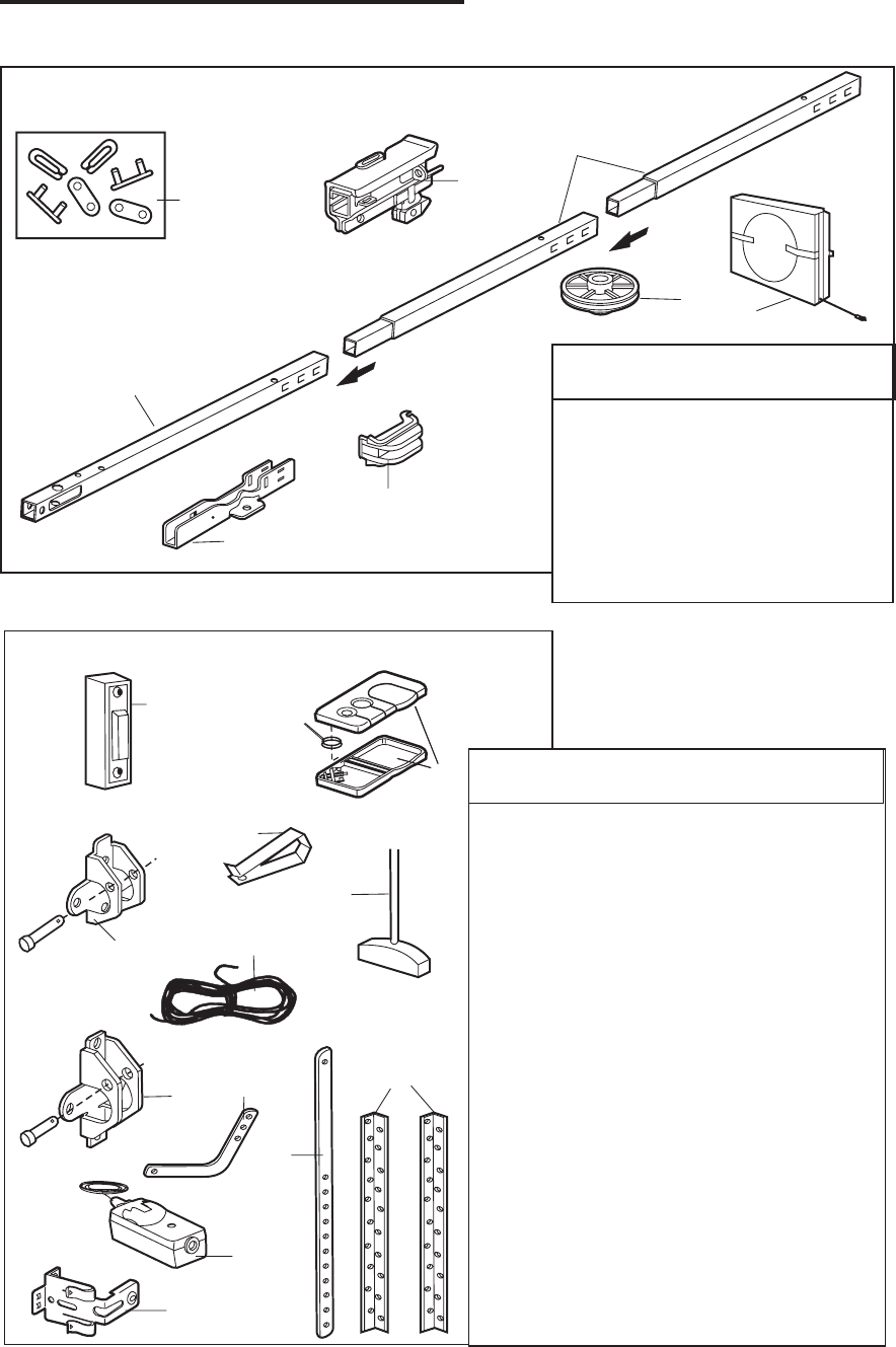
31
KEY
NO.
DESCRIPTION
1
2
3
4
5
6
7
8
Master link kit
Complete trolley assembly
Rail - front (header) section
Rail - center/back section (2)
Chain idler pulley
Chain and cable
Spreader (2)
U bracket
KEY
NO.
DESCRIPTION
1
2
3
4
5
6
7
8
9
10
11
12
13
Door control button
3-function remote control case
(no circuit board)
Two piece 3V 2016 Lithium battery
Visor clip
Emergency release rope & handle assy.
2-Conductor bell wire: white &
white/red
Header bracket w/clevis pin & fastener
Door bracket w/clevis pin & fastener
Curved door arm. section
Straight door arm section
Hanging brackets
Safety sensor kit: Emitter andReceiver
Safety sensor bracket
Not shown:
Assy & Installation hardware bag
(see page 6)
Owner's manual
12
3
4
56
7
8
1
2
3
4
5
6
7
89
10
11
12
13
Rail Assembly Parts
REPAIR PARTS
NOTICE
32
1
23
4
5
6
7
8
9
10
11
12
13
14
15
16
17 13
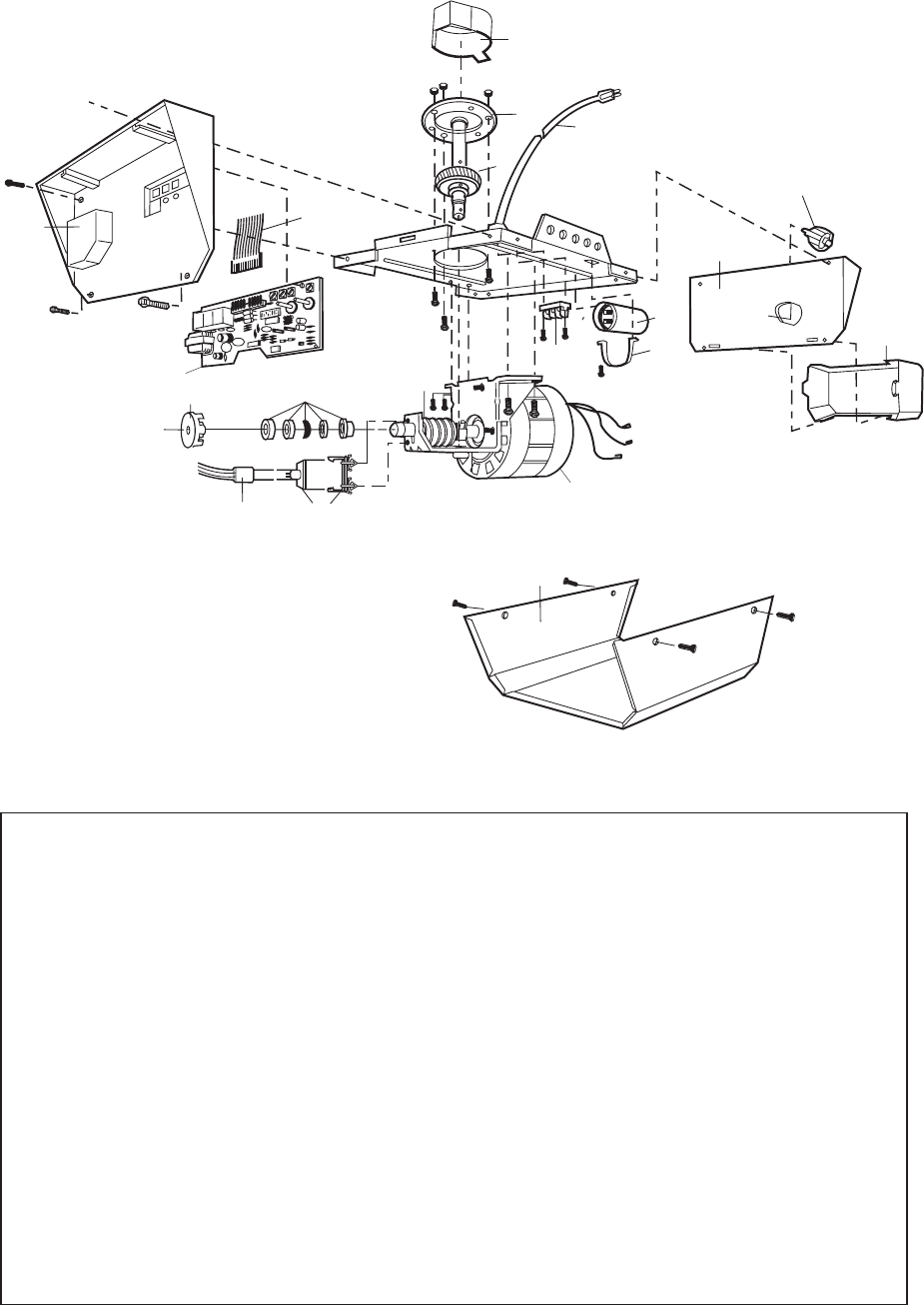
Motor Unit Assembly Parts
KEY
NO.
DESCRIPTION
1
2
3
4
5
6
7
8
9
KEY
NO.
DESCRIPTION
Sprocket cover,
Gear and sprocket assembly
Complete with: Spring washer,
Thrust washer, Retaining ring,
Bearing plate, Roll pins (2),
Drive gear and worm gear,
Helical gear w/retainer and
grease
Drive/worm gear kit w/grease
Roll pins (2)
Line cord
End panel w/all labels
Light socket
Light Lens
Capacitor
Capacitor bracket
Terminal block w/screws
10
11
12
13
14
15
16
17
Universal replacement motor &
bracket assembly
Complete with: Motor, worm,
bracket, bearing assembly,
RPM sensor
Cover
RPM sensor assembly
Wire harness assembly w/plug
Interrupter cup assembly
Receiver logic board assembly
End panel
NOT SHOWN
Opener assembly hardware kit
(includes screws not designated
by a number in illustration).
Shaft bearing ASM

WARRANTY
NIKOTA WARRANTY
FULL 90-DAY WARRANTY ON GARAGE DOOR OPENER
For 90 days from the date of purchase, Nikota will repair this Garage DoorOpener, free of charge, if defective in material or workmanship.
LIMITED WARRANTY
From the 91st day until one year from the date of purchase, Nikota will furnish replacement parts for any defective parts, free of charge.
You pay for labor.
LIMITED WARRANTY ON MOTOR
1/2HP MOTOR: After 1 year and through 5 years, if the motor on this Garage Door Opener is defective, Nikota will furnish a
replacement motor, free of charge. You pay for labor.
LIMITATION ON LIABILITY
NIKOTA WILL NOT BE LIABLE FOR LOSS OR DAMAGE TO PROPERTY OR ANY INCIDENTAL OR CONSEQUENTIAL LOSS OR
EXPENSE FROM PROPERTY DAMAGE DUE DIRECTLY OR INDIRECTLY TO THE USE OF THIS PRODUCT. Some states do not
allow the exclusion or limitation of incidental or consequential damages, so the above limitation or exclusion may not apply to you.
This warranty does not cover light bulbs or repair parts necessary because of operator abuse or negligence, including the failure to
install, adjust and operate this garage door opener according to instructions contained in the owner's manual.
WARRANTY SERVICE IS AVAILABLE BY CONTACTING THE NEAREST NIKOTA SERVICE CENTER IN THE UNITED STATES.
This warranty applies only while this product is in use in the United States.
This warranty gives you specific legal rights, and you may also have other rights which vary from state to state.
NIKOTA Tools Company, P. O. BOX 7340 ALHAMBRA, C A91802
33
Get it fixed, at your home or ours!
For repair of major brand appliances in your own home...
no matter who made it, no matter who sold it!
877-4-NIKOTA
7:00AM---6:00PM
WWW.NIKOTAUSA.COM
For the replacement parts, accessories and owner's manuals
that you need to do-it-yourself, call NIKOTA!
877-4-NIKOTA
7:00AM---6:00PM
WWW.NIKOTAUSA.COM
Add: P. O. BOX 7340 PHONE: 877-4-NIKOTA
ALHAMBRA, C A91802 WEB SITE: WWW.NIKOTAUSA.COM