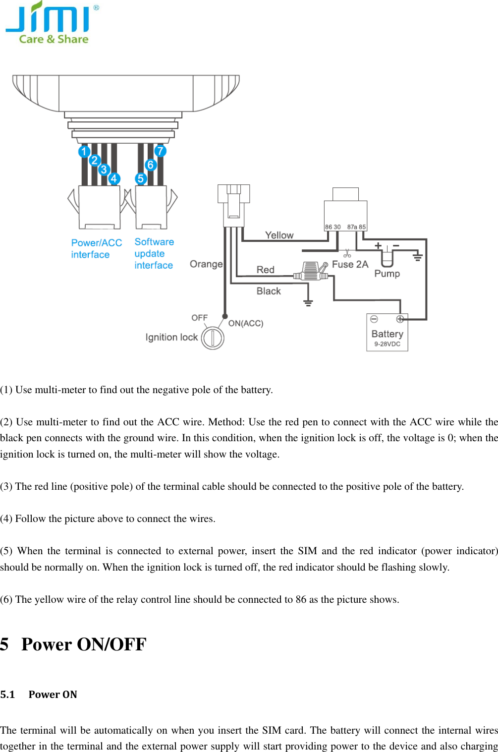
Jimi Electronic JM01 Vehicle GPS tracker User Manual

Shenzhen Jimi Electronic Co., Ltd. Vehicle GPS tracker

User manual

                                                       User Manual
  Please read this manual carefully before attempting installation and online activation. Pictures are for indication and illustration purposes only 1  Accessories   Pictures are for indication and illustration purposes only.  NOTE: After opening the packing box, please check if the accessories are complete. If there is anything missing, please contact your distributor.  2 Interface descriptions
  3 LED status indicator and wiring   3.1 Red LED(power/working status indicator) Status Meaning Quick flashing   Low battery Slow flashing   Fully charged Continuously in bright Charging Continuously in dark No battery/troubleshoot 3.2 Blue LED(GPS signal indicator) Status   Meaning Quick flashing   Searching GPS signal Slow flashing   GPS signal has successfully Continuously in dark GPS stops working 3.3 Green LED(GSM signal indicator) Status Meaning Quick flashing   GSM initialization Slow flashing   GPRS online Continuously in dark No GSM signal or no SIM card installed     3.4 Armed   When red/green/blue 3 LED lights are flashing twice in cycle, it means the terminal is armed.
  3.5 Function of the wires  No. Function Color Function Illustration 1 V+ Red Positive pole 2 V- Black Negative pole 3 ACC Orange ACC on 4 Relay Yellow Relay controlled wire   5 TX Green Send data / for backup     6 RX Blue Receive data / for backup   7 GND Purple Ground wire   4 Installation    4.1 Wiring   1:Red    2:Black      3:Orange      4:Yellow      5:Green      6:Blue      7:Purple
    (1) Use multi-meter to find out the negative pole of the battery.    (2) Use multi-meter to find out the ACC wire. Method: Use the red pen to connect with the ACC wire while the black pen connects with the ground wire. In this condition, when the ignition lock is off, the voltage is 0; when the ignition lock is turned on, the multi-meter will show the voltage.    (3) The red line (positive pole) of the terminal cable should be connected to the positive pole of the battery.    (4) Follow the picture above to connect the wires.    (5)  When  the  terminal is connected  to  external  power,  insert  the  SIM  and  the  red  indicator  (power  indicator) should be normally on. When the ignition lock is turned off, the red indicator should be flashing slowly.    (6) The yellow wire of the relay control line should be connected to 86 as the picture shows.   5 Power ON/OFF   5.1  Power ON The terminal will be automatically on when you insert the SIM card. The battery will connect the internal wires together in the terminal and the external power supply will start providing power to the device and also charging
  the battery.        5.2 GSM&GPS signal searching After the power is on, it will start searching the GSM and GPS signal.  During this period, the green indicator (GSM indicator) will be  flashing  while  the  blue  indicator will be flashing quickly.  When  the blue indicator is flashing slowly, it means GPS has located.   5.3 Power OFF   Pull out the SIM card, the terminal will be off.   6 Parameters setting 6.1 Set APN Please send SMS command to the number of terminal so as to set up the APN parameter. The terminal will reply “OK” automatically after setting successfully.   Send SMS command: APN,APN’s name# e.g: APN, internet# NOTE: The  APN  of  some countries  have  user  name and  password,  you  may need  to  send  SMS  command  as follows: Send SMS command: APN,APN’s name, user name, password# e.g: APN, internet, CLIENTE, AMENA# 6.2 Set DNS Please send SMS command to the number of terminal so as to set up the DNS parameter. The terminal will reply “OK” automatically after setting successfully.   Send SMS command: SERVER,1,DNS,Port,0# e.g. SERVER,1,JM01.szdatasource.com,8841,0# 6.3 Set SOS Number   (1) Add SOS number Via SMS command Send SMS command: SOS, A,number1,number2,number3 #(A means add number).   You can set 3 SOS numbers in maximum. If set successfully, the terminal will reply “ok”. e.g. SOS,A, 13510****60,135116****6,136126****8#  (set all 3 SOS numbers) SOS,A, 13510****60# (set the first SOS number) SOS,A, ,135116****6# (set the second SOS number) SOS,A, , ,136126****8# (set the third SOS number)
   (2) Delete SOS Numbers Send SMS command: SOS, D,1,2,3# (D means delete SOS number) e.g. SOS, D,1# means delete the first number    SOS, D,3# means delete the third number If you do not know the sequence number, you can also delete the number by SMS command like this: SOS, D, number# e.g. SOS, D, 135278****0# means delete this SOS number directly. It will reply “OK” if the number is deleted successfully.    (3) Add SOS numbers via platform You can set SOS number via the platform after activating the terminal. 6.4 Set Center Number Send SMS command from the SOS number to set the Center Number.   (1) Add Center Number: Send SMS command: CENTER, A, number#   e.g. CENTER,A, 135278****0# (2) Delete Center Number Send SMS command :CENTER,D, number# e.g. CENTER,D, 135278****0# NOTE: Center Number can be set ONLY by SOS numbers.   6.5 Check current parameters Send SMS command: PARAM# The  terminal  will  reply  messages  including:  IMEI  number,  GPRS  upload  interval,  time  interval  that  GPS  is activated when ACC is off, SOS numbers, center number, sensor alarm interval, defense time and time zone.   6.6 Set GPS data upload interval   (1) Upload by interval   The default upload interval is 20 seconds, which means every 20 seconds the terminal will upload its location data to the platform. The interval can be set by sending SMS command: TIMER,T1,T2# (5≤T≤18000 seconds) e.g. TIMER,20,30# It means when ACC is on, GPS data upload interval is 20 seconds; when ACC is off, GPS data upload interval is 30 seconds.    (2) Upload by distance   Send SMS command: DISTANCE,D# (100≤D≤10000 meters)   e.g. DISTANCE,300#
  It means for every 300 meters, the terminal will upload GPS data to platform.   NOTE: if the upload interval is short, the GPRS current will add up. Please set the suitable upload interval.   6.7 Corners upload (ON as default)   The  terminal  will upload  GPS  data  to  the platform  when  the  vehicle  is  turning  (the turning  angle  reaches  the pre-set value).   NOTE: if the speed is too low during turning, the GPS data will be not able to upload to the platform.       Send SMS command: ANGLEREP,OFF# to turn it off.   6.8 Arm time interval     When the vehicle is turned off (ACC low) and stays off in 3 minutes(pre-set), the terminal will enter arm status. During this status, if  the terminal detects 6 vibrations  (default)  and  the  vehicle  still  stays  off (ACC off) in 30 seconds, it will activate vibration alarm.   Send SMS command: DEFENSE,T# (1≤T≤60 minutes)   e.g. DEFENSE,15# It means after 15 minutes the vehicle is turned off, the terminal will enter defense mode.   6.9 Reboot the terminal   Send SMS command: RESET#   When the terminal receives the command, it will reboot in 20 seconds.    7 Operation   7.1 Check location (1) Ask for coordinates Send SMS command from SOS number to the terminal: WHERE#   Only SOS number can apply for replying longitude and latitude from the terminal. If GPS is located, it will reply latest longitude and latitude information.  e.g. Lat:N22.571285,Lon:E113.877115,Course:42.20,Speed:0.0740,DateTime:10-11-23 22:28   If GPS is not located at all, the terminal will reply: “NO DATA!”  (2)Ask for Google link Send SMS command from SOS number to the terminal: URL# If GPS is located, it will reply google link of latest longitude and latitude.   e.g.    Google link reply           <DateTime:10-11-23 23:42:51> http://maps. google.com/maps?q=N22.571490,E113.877103
  (3) Check platform   The terminal will send position information to the platform server timely. Users can check the position on the platform.   The platform website: www.cootrack.com   Please contact your supplier for the login methods and operations. 7.2 Vibration Alarm (ON as default) When the vehicle is turned off (ACC low) and stays off for 3 minutes (pre-set), the terminal will enter arm status. During this time, if the terminal detects 6 times vibrations (default) and the vehicle still stays off (ACC off) in 30 seconds, it will activate vibration alarm. The terminal will upload longitude and latitude data to the platform. Then the platform will send the google link to SOS number.    e.g. GPS information link: “vibration alarm: <DateTime:10-11-23 23:42:51> http://maps. google.com/maps?q=N22.571490,E113.877103”  If you do not want to receive vibration alarm messages, send SMS command: SENALM,OFF# to turn it off. 7.3 Cable cut-off Alarm (ON as default) When the terminal cable is cut off, the cable cut-off alarm will be activated. The terminal will send the alarm to the platform and upload longitude and latitude data. And the platform will send google link to SOS number.   e.g. GPS information link: “Cut Power! <DateTime:10-11-23 23:42:51> http://maps. google.com/maps?q=N22.571490,E113.877103” Send SMS command: POWERALM,OFF# to turn it off.   7.4 Low Battery Alarm (ON as default)   When the battery is low, the terminal will send SMS to SOS numbers and upload alarm information to platform. Send SMS command: BATALM,OFF# to turn off the alarm.    7.5 Moving alarm (OFF as default) Send SMS command: MOVING,ON,R# (100≤R≤1000 meters, 300 is recommended) In the situation where ACC becomes low, if the vehicle is moved over 300 meters (pre-set) from the latest location,     the terminal will send moving alarm to the platform. SOS number will receive moving alarm message.   e.g.   Attention! The vehicle is moved. <DateTime:10-11-2323:42:51>http://maps.google.com/maps?q=N22.571490,E113.877103   Send SMS command: MOVING,OFF# to turn off the alarm
  7.6 Petrol cut-off   (1) Cut-off petrol   When the vehicle was stolen, you can cut off the petrol on the platform in the situation where the speed is under 20km/h. Platform password is needed. Or you can send SMS command to the device.   Send SMS command: RELAY,1# to cut off petrol.   (2) Restore petrol   You can restore petrol on the platform. Platform password is needed.   Send SMS command: RELAY,0# to restore petrol.   NOTE: Petrol cut-off and restore commands can be executed by the center number ONLY.   8 Trouble shooting If there is any problem while operating the terminal, please refer to the following table, or contact your supplier. Common problems Causes Solution Bad reception Near the tall building or in the basement Change to a place with good signal The terminal cannot be turned on No battery power Change a new battery Cannot connect to the network SIM card is not inserted correctly Check the SIM card The sheet mental of SIM card is dusty Wipe it clean Invalid SIM card Contact your SIM card operator   Out of GSM service area Move  back  to  the  GSM  service covered area. Weak signal Try again in a strong signal area Cannot charge Voltage is out of charging range of the charger Change to the proper voltage Poor contact Check if the plug is in
  Cannot check   address information GPRS function is not activated Please contact the SIM card operator to activate GPRS Cannot get the position data ①restart the terminal ②contact with your supplier It is not a SOS number set SOS number   FCC Statement 1. This device complies with Part 15 of the FCC Rules. Operation is subject to the following two conditions: (1) This device may not cause harmful interference. (2) This device must accept any interference received, including interference that may cause undesired operation. 2. Changes or modifications not expressly approved by the party responsible for compliance could void the user's authority to operate the equipment. NOTE:   This equipment has been tested and found to comply with the limits for a Class B digital device, pursuant to Part 15 of the FCC Rules. These limits are designed to provide reasonable protection against harmful interference in a residential installation. This equipment generates uses and can radiate radio frequency energy and, if not installed and used in accordance with the instructions, may cause harmful interference to radio communications. However, there is no guarantee that interference will not occur in a particular installation. If this equipment does cause harmful interference to radio or television reception, which can be determined by turning the equipment off and on, the user is encouraged to try to correct the interference by one or more of the following measures: Reorient or relocate the receiving antenna. Increase the separation between the equipment and receiver. Connect the equipment into an outlet on a circuit different from that to which the receiver is connected.   Consult the dealer or an experienced radio/TV technician for help.  RF Exposure Warning Statements This device must be installed to provide a separation distance of at least 20 cm from all persons and must not be co-located or operating in conjunction with any other transmitter.

Navigation menu