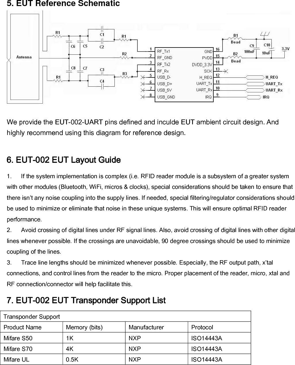
Jogtek NFC-002 HF RFID Module User Manual 1204

Jogtek Corp. HF RFID Module 1204

User Manual

User's manual 1. INTRODUCTION The EUT-002 is a smallest module in the market and highly integrated transmission module for contactless communication at RFID 13.56 MHz (HF) applications. Its simplified interface, ultra low power consumption, standard RF output port and superior performance, make it easy to integrate any device with EUT/RFID technology. The EUT-002 is a highly integrated transmission module for contactless communication at 13.56 MHz. The embedded firmware handles the ISO 14443A and MIFARE reader protocol as well as the basic FeliCa  Reader protocol and the complete EUT IP-1 protocol.  1.1 Module and EUT Features ■ Module profile and Footprint  20(mm)x20(mm)x 3.2(mm) ■ EUT profile and Footprint  90(mm)x60(mm)x 8(mm) ■ Internal oscillator to connect 27.12 MHz crystal ■ Supports ISO/IEC 14443A/Mifare ■ Supports Mifare Classic encryption in reader/writer mode ■ Supports Mifare higher transfer speed communication at 212 kbit/s and 424 kbit/s ■ Supports contactless communication according to the FeliCa scheme at 212 KBaud and 424 KBaud ■ Integrated RF interface for EUT IP-1 up to 424 Kbaud ■ Ultra low power consumption ■ 2.5 - 3.6 V power supply ■ Easy Connection to Flex antenna ■ Supported High Speed Serial UART (similar to RS232 with 0 and PVDD voltage levels) host interface  1.2 Operating modes: The EUT-002 supports 2 different operating modes •  Reader/writer mode for ISO14443A Mifare and FeliCa cards •  EUT Mode (EUT IP-1 mode) The Analog circuitry handles the modulation and demodulation of the analog signals according to the   reader /writer mode and EUT mode communication scheme. The RF level detector detects the presence of an external RF field at 13.56 MHz. The mode detector detects a MIFARE, FeliCa or EUT coding of an incoming signal in order to prepare the internal receiver to demodulate signals that are sent to the EUT-002 Module. The integrated contactless UART interface and the firmware handle the protocol requirements for the communication schemes including the RF based protocols as well as the protocols for host communication. The microcontroller with its embedded firmware allows autonomous management of communication both on the RF interface and with the host. Various host interfaces are implemented to fulfil different customer requirements.
1.2.1  Reader/Writer Operating mode The EUT-002  can act as a reader / writer for ISO14443A/MIFARE® or FeliCa cards.       In the reader/ writer mode the EUT-002 EUT enables communication to a passive ISO14443A/MIFARE or FeliCa card. The EUT-002’s firmware and contactless UART handle the ISO 14443A/MIFARE and FeliCa protocol.  1.2.2  EUT MODE EUT communication differentiates between an active and a passive communication.     Active EUT Mode means both the initiator and the target are using their own RF field for the communication.     Passive EUT Mode means that the target answers to an initiator command in a load modulation scheme.  The initiator is active i.e. generating the RF field.  initiator: generates RF field @ 13.56 MHz and starts the EUT communication Target: responds to initiator commands either using load modulation scheme (RF field continuously generated by Initiator) or using modulation of self generated RF field (no RF field generated by initiator)
2.Mechanical Characteristics 2.1 Dimensions  2.2 -X  Pinning Diagram  EUT-002 Pin Assignment (Top view) 2.3 -X Pin Description Port Pin I/O  Description RF_Tx1 1  O  Transmitter 1: delivers the modulated 13.56 MHz energy carrier RF_GND 2 PWR Transmitter Ground RF_Tx2 3  O  Transmitter 2: delivers the modulated 13.56 MHz energy carrier RF_Rx 4  I  Receiver Input: Input pin for the reception signal, which is the load modulated 13.56 MHz energy carrier from the antenna circuit USB_D- 5 IO  USB D- USB_D+ 6 IO  USB D+ USB_5V 7  PWR  USB power supply. USB_GND 8 PWR Module substrate ground IRQ  9  IO  Interrupt request: Output to signal an interrupt event to the host UART_Rx 10  IO  Serial UART Rx (similar to RS232 with 0 and PVDD voltage levels) UART_Tx 11  IO  Serial UART Tx (similar to RS232 with 0 and PVDD voltage levels) H_REQ  12  IO  Request or acknowledge line from the host SCK 13 IO Serial interface clock. In test mode this signal is used as input and output test signal DVdd+3.3V  14  PWR  Digital Power Supply PVdd 15 PWR Pad power supply GND 16 PWR Module substrate ground
2.4 Absolute maximum ratings Symbol  Parameter  Conditions  Min  Typ  Max   Unit USB_5V  USB Supply Voltage (USB mode)   4.2     5    5.25      V Supply Voltage (non USB mode) VBUS = DVDD; Gnd = 0 V 2.5    3.3    3.6       V DVdd_3.3V Supply Voltage  DVDDGnd = 0 V2.5    3.3    3.6       V PVDD Supply Voltage for host interface Gnd = 0 V 1.6           3.6       V IUSB_5V Maximum load current (USB mode) measured on VBUS 180     mA Maximum Inrush current limitation At power up (curlimoff =0)               130     mA IDVDD Transmitter Supply Current  During RF Transmission, DVDD= 3 V60   130     mA Ptotusb continuous total power dissipation in USB mode Tamb = -30 to +85 °C0.6    W Ptot continuous total power dissipation in non USB mode Tamb = -30 to +85 °C0.2     W Tamb operating ambient temperature   -30               +85    °C  3.EUT Mechanical Characteristics 3.1 EUT(Component-U1)-MAX3232 Pin Description RS-232 Serial Protocol(+12V~-12V) to UART TTL Protocol(+3V~-3V)  Port Pin I/O  Description C1+  1  PWR  Positive Terminal of Voltage-Doubler Charge-Pump Capacitor U+  2  PWR  +5.5V Generated by the Charge Pump C1-  3  PWR  Negative Terminal of Voltage-Doubler Charge-Pump Capacitor C2+  4  PWR  Positive Terminal of Voltage-Doubler Charge-Pump Capacitor C2- 5  PWR  Negative Terminal of Voltage-Doubler Charge-Pump Capacitor U-  6  PWR  -5.5V Generated by the Charge Pump T2OUT 7 IO RS-232 Transmitter Outputs R2IN  8  IO  RS-232 Receiver Inputs R2OUT 9 IO TTL/CMOS Receiver Outputs T2IN 10 IO TTL/CMOS Transmitter Inputs T1IN 11 IO TTL/CMOS Transmitter Inputs R1OUT 12 IO TTL/CMOS Receiver Outputs R1IN  13  IO  RS-232 Receiver Inputs T1OUT 14 IO RS-232 Transmitter Outputs GND 15 PWR Ground VDD 16 PWR Power Supply
3.2 EUT(Component-U2)-XX1117 Pin Description Power 5V to 3.3v LDO  Port Pin I/O  Description Vin  1  PWR  DC Input Voltage Vout  2  PWR  DC Output Voltage GND 3 PWR Ground N.C. 4  (Connected  to DC Output Voltage)  4. EUT-002 Host interfaces Two different host interface interfaces are proposed with the EUT-002 Module. One is using the USB interface and the other one use the HSU (High Speed UART: similar to RS232 with 0 and PVdd voltage levels) interface. 4.1 High speed UART interface Port Pin I/O  Description IRQ  9  IO  Interrupt request: Output to signal an interrupt event to the host UART_Rx 10  IO  UART RX (Serial reception line of the EUT-002-UART) UART_Tx 11  IO  UART TX (Serial transmission line of the EUT-002-UART) H_REQ  12  IO  Request or acknowledge line from the host  HSU interface default configuration is: Data bit : 8 bits       Parity bit : none      Stop bit : 1 bit       Baud rate : 9600 bauds   Data order : LSB first    Baudrate: Default baudrate is 9600 bauds. EUT-002 HSU is up to 1288 kbauds. The HSU speed is changeable with SetSerialBaudrate command (command code 10h, parameter = baudrate). The host controller must send an ACK frame after reception of SetSerialBaudrate response. EUT-002 will switch to the new baudrate only after reception of this ACK frame.  4.2 How to change HSU speed in SCRTester? To activate sending of ACK frame after reception of a command, use “.config(10,01)” in SCRTester. Example of script file: .config(10,01);       // SCRTester is forced to send the optional ACK 10 06;      // SetSerialBaudrate (460.8 kbauds) .config(00, 460800);     // Change baudrate of SCRTester to 460.8 kbaud .config(10, 00);       // Deactivate the optional ACK option  Handshake mode in HSU
4 lines are connected between the host controller and EUT-002 Module: UART_Rx, UART_Tx, H_REQ and IRQ. Remark: in handshake mode, IRQ line is not set low by EUT-002 when ACK frame is ready (different behaviour than standard mode + use of IRQ). 00h 01h 02h 03h 04h 05h 06h 07h 08h 9.6 kbauds 19.2 kbauds 38.4 kbauds 57.6 kbauds 115.2 kbauds230.4 kbauds460.8 kbauds921.6 kbauds1288 kbauds
5. EUT Reference Schematic We provide the EUT-002-UART pins defined and inculde EUT ambient circuit design. And highly recommend using this diagram for reference design.  6. EUT-002 EUT Layout Guide 1. If the system implementation is complex (i.e. RFID reader module is a subsystem of a greater system with other modules (Bluetooth, WiFi, micros & clocks), special considerations should be taken to ensure that there isn’t any noise coupling into the supply lines. If needed, special filtering/regulator considerations should be used to minimize or eliminate that noise in these unique systems. This will ensure optimal RFID reader performance. 2. Avoid crossing of digital lines under RF signal lines. Also, avoid crossing of digital lines with other digital lines whenever possible. If the crossings are unavoidable, 90 degree crossings should be used to minimize coupling of the lines. 3. Trace line lengths should be minimized whenever possible. Especially, the RF output path, x’tal connections, and control lines from the reader to the micro. Proper placement of the reader, micro, xtal and RF connection/connector will help facilitate this. 7. EUT-002 EUT Transponder Support List Transponder Support Product Name  Memory (bits)  Manufacturer  Protocol Mifare S50  1K  NXP  ISO14443A Mifare S70  4K  NXP  ISO14443A Mifare UL  0.5K  NXP  ISO14443A
8. SALES AND SERVICE INFORMATION To obtain information about Jogtek Corp. products and technical support, reference the following information. jogtek corp. 7F., No. 300 YangGuang Street, NeiHu District, Taipei City 114, Taiwan Tel : +886-2-6606-9066                                     Fax : +886-2-2659-6884 www.jogtek.com  Federal Communication Commission Interference Statement This equipment has been tested and found to comply with the limits for a Class B digital device, pursuant to Part 15 of the FCC Rules.  These limits are designed to provide reasonable protection against harmful interference in a residential installation.  This equipment generates, uses and can radiate radio frequency energy and, if not installed and used in accordance with the instructions, may cause harmful interference to radio communications.  However, there is no guarantee that interference will not occur in a particular installation.  If this equipment does cause harmful interference to radio or television reception, which can be determined by turning the equipment off and on, the user is encouraged to try to correct the interference by one of the following measures: z Reorient or relocate the receiving antenna. z Increase the separation between the equipment and receiver. z Connect the equipment into an outlet on a circuit different from that to which the re-ceiver is connected. z Consult the dealer or an experienced radio/TV technician for help.  FCC Caution: Any changes or modifications not expressly approved by the party responsible for compliance could void the user's authority to operate this equipment.  This device complies with Part 15 of the FCC Rules. Operation is subject to the following two conditions: (1) This device may not cause harmful interference, and (2) this device must accept any interference received, including interference that may cause undesired operation.  This device and its antenna(s) must not be co-located or operating in conjunction with any other antenna or transmitter.
IMPORTANT NOTE: This module is intended for OEM integrator. The OEM integrator is still responsible for the FCC compliance requirement of the end product, which integrates this module.  Any changes or modifications not expressly approved by the manufacturer could void the user's authority to operate this equipment. USERS MANUAL OF THE END PRODUCT: In the users manual of the end product, the end user has to also be informed that any changes or modifications not expressly approved by the manufacturer could void the user's authority to operate this equipment. If the size of the end product is smaller than 8x10cm, then additional FCC part 15.19 statement is required to be available in the users manual: This device complies with Part 15 of FCC rules. Operation is subject to the following two conditions: (1) this device may not cause harmful interference and (2) this device must accept any interference received, including interference that may cause undesired operation. LABEL OF THE END PRODUCT: The final end product must be labeled in a visible area with the following " Contains TX FCC ID: VZPNFC-002 ". If the size of the end product is larger than 8x10cm, then the following FCC part 15.19 statement has to also be available on the label:    This device complies with Part 15 of FCC rules. Operation is subject to the following two conditions: (1) this device may not cause harmful interference and (2) this device must accept any interference received, including interference that may cause undesired operation.

Navigation menu