John Deere 5310 S Users Manual 013231UNIT
!! John-29 John Deere Lawn Mower Manuals - Lawn Mower Manuals – The Best Lawn Mower Manuals Collection
5310 S to the manual 582cbc51-c2e6-4e3c-8fbc-f6da9ec42a44
2015-02-03
: John-Deere John-Deere-5310-S-Users-Manual-466078 john-deere-5310-s-users-manual-466078 john-deere pdf
Open the PDF directly: View PDF ![]() .
.
Page Count: 172 [warning: Documents this large are best viewed by clicking the View PDF Link!]
- Contents
- Safety
- Recognize Safety Information
- Understand Signal Words
- Follow Safety Instructions
- Prevent Machine Runaway
- Operate Tractor Safely
- Use Caution on Hillsides
- Shift to Low Gear on Hills
- Avoid Tipping
- Freeing a Mired Machine
- Park Tractor Safely
- Handle Fuel Safely—Avoid Fires
- Prepare for Emergencies
- Wear Protective Clothing
- Protect Against Noise
- Stay Clear of Rotating Drivelines
- Use Safety Lights and Devices
- Safely Transporting the Tractor
- Tow Loads Safely
- Keep Riders Off Machine
- Practice Safe Maintenance
- Service Tractor Safely
- Work In Ventilated Area
- Support Machine Properly
- Avoid Heating Near Pressurized Fluid Lines
- Avoid High-Pressure Fluids
- Service Cooling System Safely
- Store Attachments Safely
- Prevent Acid Burns
- Service Tires Safely
- Dispose of Waste Properly
- Safety Signs
- Controls and Instruments
- Lights
- Operator's Platform
- Break-In Period
- Prestarting Checks
- Operating the Engine
- Before Starting the Engine
- Starting the Engine
- Check Instruments After Starting
- Oil Pressure Indicator
- Charging System Indicator
- Air Restriction Indicator
- Coolant Temperature Gauge
- Watch Fuel Level
- Changing Engine Speeds
- Warming Up the Engine
- Restart Stalled Engine
- Avoid Idling the Engine
- Observe Engine Work and Idle Speeds
- Working With Speed/Hour Meter
- Stopping the Engine
- Using Booster Battery
- Driving the Tractor
- Rockshaft and 3-Point Hitch
- Match Tractor Power to Implement
- 3-Point Hitch Components
- Rockshaft Control Levers
- Setting Position Control Lever Stop
- Using Rockshaft Position Control
- Using Draft Control
- Adjusting Rockshaft Rate-of-Drop/ Implement lock
- Preparing Implement
- Positioning Center Link
- Attaching Implements to 3-Point Hitch
- Adjusting Hitch Side Sway
- Leveling the Hitch
- Adjusting Lateral Float
- Adjusting Rockshaft Control Lever Friction
- Warming Hydraulic System Oil
- Remote Hydraulic Cylinders
- Drawbar and PTO
- Ballast
- Planning for Maximum Productivity
- Selecting Ballast Carefully
- Matching Ballast to Load Work
- Measuring Wheel Slip—Manually
- Ballast Limitations
- Ballasting Front End for Transport
- Ballasting Tractor
- Determining Maximum Rear Ballast
- Determining Maximum Front Ballast
- Using Cast Iron Weights
- Installing Rear Cast Iron Weights
- Using Liquid Weight
- Wheels, Tyres and Treads
- Service Tyres Safely
- Check Implement-to-Tyre Clearance
- Check Tyre Inflation Pressure
- Tyre Inflation Pressure Chart
- Tighten Wheel/Axle Hardware Correctly
- Tighten Bolts—Adjustable Front Axle
- Tighten Bolts—Rear Axle
- Observe Rear Wheel Tread Width Limitations
- Tread Settings—Multi-Position Rear Wheels
- Tread Settings—Adjustable Front Axle
- Adjust Front Axle Tread Width
- Checking Toe-In
- Adjusting Toe-In
- Transporting
- Fuels, Lubricants and Coolant
- Service and Maintenance
- Service—Every 10 Hours
- Service—Every 50 Hours
- Service—Every 250 Hours
- Service—Every 500 Hours
- Service—Every 600 Hours
- Service—Every 1250 Hours
- Service—Annually
- Service—2 Years/2000 Hours
- Service—As Required
- Service
- Additional Service Information
- Service Tractor Safely
- Engine Break-In Oil
- Work In Ventilated Area
- Using High-Pressure Washers
- Opening Hood
- Removing Side Screens
- Removing Hood
- Air Intake System Components
- Service Air Cleaner at Regular Intervals
- Checking Air Intake System
- Removing Primary Air Cleaner Element
- Cleaning Primary Element
- Washing Primary Element
- Inspecting Element
- Storing Element
- Replacing Alternator/Fan Belt
- Fuel System Components
- Bleeding Fuel System
- Do Not Modify Fuel System
- Engine Cooling System Components
- Cleaning Grille, Screens, Radiator and Oil Cooler
- Prevent Battery Explosions
- Observe Electrical Service Precautions
- Battery Access
- Removing Battery
- Checking Battery Condition
- Servicing Battery
- Charging Battery
- Battery Replacement Specifications
- Connecting Starter Wiring
- Connecting Alternator Wiring
- Locating Fusible Link
- Locating Fuses
- Fuse Size and Function
- Aiming Headlights
- Adjusting Headlights
- Replace Headlight Bulb
- Replace Tail Light and Warning Light Bulbs
- Replace Flood Lamp Bulb
- Checking Tyres
- Troubleshooting
- Tractor Storage
- Specifications
- Identification Numbers
- Lubrication Maintenance Record Charts
- John Deere Service
- Safety
- Page Numbers
- Section 05
- Section 10
- Section 15
- Section 20
- Section 25
- Section 35
- Section 40
- Section 45
- Section 50
- Section 55
- Section 60
- Section 65
- Section 70
- Section 75
- Section 80
- Section 85
- Section 90
- Section 95
- Section 100
- Section 110
- Section 115
- Section 115
- Section 120
- Section 125
- Section 130
- Section 135
- Section 140
- Section 145
- Section 150
- Section 155
- Section 160
- Section 165
- Section 170
- Untitled
- B
5310 S
Tractor
OPERATOR’S MANUAL
5310 S Tractor
OMRE247111 Issue G6 (ENGLISH)
CALIFORNIA
Proposition 65 Warning
Diesel engine exhaust and some of its constituents are
known to the State of California to cause cancer, birth
defects, and other reproductive harm.
If this product contains a gasoline engine:
WARNING
The engine exhaust from this product contains chemicals
known to the State of California to cause cancer, birth
defects or other reproductive harm.
The State of California requires the above two warnings.
John Deere Equipment Private Limited
Printed in India.

Introduction
AG,OUO6075,97 –19–21FEB06–1/2
Foreword
READ THIS MANUAL carefully to learn how to operate
and service your machine correctly. Failure to do so
could result in personal injury or equipment damage.
This manual and safety signs on your machine may
also be available in other languages (see your John
Deere dealer to order).
THIS MANUAL SHOULD BE CONSIDERED a
permanent part of your machine and should remain
with the machine.
MEASUREMENTS in this manual are given in both
metric and customary U.S. unit equivalents. Use only
correct replacement parts and fasteners. Metric and
inch fasteners may require a specific metric or inch
wrench.
RIGHT-HAND AND LEFT-HAND sides are determined
by facing the direction of forward travel.
WRITE TRACTOR SERIAL (CHASSIS) NUMBER in
the Specification or Identification Numbers section.
Accurately record all the numbers to help in tracing the
machine should it be stolen. Your dealer also needs
these numbers when you order parts. File the
identification numbers in a secure place off the
machine.
SETTING FUEL DELIVERY BEYOND PUBLISHED
factory specifications or otherwise overpowering will
result in loss of warranty protection for this machine.
BEFORE DELIVERING THIS MACHINE, your dealer
performed a predelivery inspection. After operating for
the first 100 hours, schedule an after-sale inspection
with your dealer to ensure best performance.
THIS TRACTOR IS DESIGNED SOLELY for use in
customary agricultural or similar operations
("INTENDED USE"). Use in any other way is
considered as contrary to the intended use. The
manufacturer accepts no liability for damage or injury
resulting from this misuse, and these risks must be
borne solely by the user. Compliance with and strict
adherence to the conditions of operation, service and
repair as specified by the manufacturer also constitute
essential elements for the intended use.
THIS TRACTOR SHOULD BE OPERATED, serviced
and repaired only by persons familiar with all its
particular characteristics and acquainted with the
relevant safety rules (accident prevention). The
accident prevention regulations, all other generally
recognized regulations on safety and occupational
medicine and the road traffic regulations must be
observed at all times. Any arbitrary modifications
carried out on this tractor will relieve the manufacturer
of all liability for any resulting damage or injury.
082206
PN=2
Introduction
AG,OUO6075,97 –19–21FEB06–2/2
PY5155 –UN–21AUG05
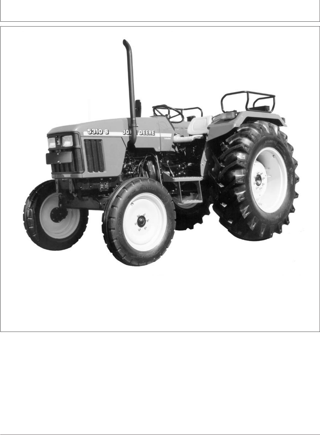
John Deere 5310 S tractor
NOTE: Tractors shown may have optional equipment.
082206
PN=3

Introduction
082206
PN=4

Contents
Page Page
Safety ................................05-1 Working With Speed/Hour Meter ............45-7
Stopping the Engine......................45-8
Safety Signs ...........................10-1 Using Booster Battery.....................45-8
Controls and Instruments Driving the Tractor
Tractor Controls .........................15-1 Operator Training Required ................50-1
Instrument Panel ........................15-3 Driving on Public Roads ...................50-1
Operating Transmission ...................50-3
Lights Shifting Transmission .....................50-3
Light Switch Positions.....................20-1 Selecting a Gear ........................50-4
Using Headlights ........................20-2 Using Brakes ...........................50-4
Using High Beam Indicator.................20-2 Using Differential Lock ....................50-5
Using Tail Lights.........................20-3 Stopping Tractor.........................50-6
Using Turn Signals.......................20-4
Using Hazard Lights ......................20-5 Rockshaft and 3-Point Hitch
Using Flood Lamp .......................20-6 Match Tractor Power to Implement...........55-1
Seven-Terminal Outlet—If Equipped..........20-6 3-Point Hitch Components .................55-1
Rockshaft Control Levers ..................55-2
Operator’s Platform Setting Position Control Lever Stop ..........55-2
Selecting Seat Position....................25-1 Using Rockshaft Position Control ............55-3
Adjusting Ride Comfort....................25-1 Using Draft Control.......................55-4
Adjusting Rockshaft Rate-of-Drop/
Break-In Period Implement lock ........................55-5
Observe Engine Operation Closely...........35-1 Preparing Implement .....................55-5
Break-In Service.........................35-1 Positioning Center Link....................55-6
Attaching Implements to 3-Point Hitch ........55-7
Prestarting Checks Adjusting Hitch Side Sway .................55-8
Service Daily Before Start-Up...............40-1 Leveling the Hitch........................55-9
Adjusting Lateral Float ...................55-10
Operating the Engine Adjusting Rockshaft Control Lever Friction ....55-10
Before Starting the Engine .................45-1 Warming Hydraulic System Oil .............55-11
Starting the Engine.......................45-2
Check Instruments After Starting ............45-3 Remote Hydraulic Cylinders
Oil Pressure Indicator.....................45-3 Use Correct Hose Tips ....................60-1
Charging System Indicator .................45-3 Control Lever and Coupler Identification—If
Air Restriction Indicator ...................45-4 Equipped ............................60-1
Coolant Temperature Gauge ...............45-4 Connecting Hoses .......................60-2
Watch Fuel Level ........................45-4 Connecting Single-Acting Cylinder ...........60-3
Changing Engine Speeds..................45-5 Correcting Reversed Cylinder Response ......60-3
Warming Up the Engine ...................45-5
Restart Stalled Engine ....................45-6 Neutral Lever Position ....................60-3
Avoid Idling the Engine....................45-6
Observe Engine Work and Idle Speeds .......45-7
Continued on next page
All information, illustrations and specifications in this manual are based on
the latest information available at the time of publication. The right is
reserved to make changes at any time without notice.
COPYRIGHT
2003
DEERE & COMPANY
Moline, Illinois
All rights reserved
A John Deere ILLUSTRUCTION
Manual
i
082206
PN=1

Contents
Page Page
Extending/Retracting Cylinder...............60-4 Fill Fuel Tank ...........................85-3
Lubricant Storage ........................85-3Disconnecting Hoses .....................60-5 Diesel Engine Coolant ....................85-4
Use Correct Transmission-Hydraulic Filter
Drawbar and PTO Element .............................85-5
Observe Drawbar / Wagon Hitch Load Transmission and Hydraulic Oil .............85-5
Limitations............................65-1 Grease ................................85-6
Stay Clear of Rotating Drivelines ............65-1
Attaching PTO-Driven Implement ............65-2
Operating Tractor PTO (Standard) ...........65-3 Service and Maintenance
Operating Tractor Dual PTO (Optional) .......65-4 Observe Service Intervals..................90-1
Adjusting PTO Clutch Operating Rod .........65-5 Break-In Service.........................90-1
Service Intervals.........................90-2
Ballast
Planning for Maximum Productivity...........70-1 Service—Every 10 Hours
Selecting Ballast Carefully .................70-1 Check Engine Oil Level ...................95-1
Matching Ballast to Load Work..............70-1 Check Coolant Level .....................95-1
Measuring Wheel Slip—Manually ............70-2 Drain Water and Sediment From Fuel
Ballast Limitations........................70-3 Tank and Fuel Filter ....................95-2
Ballasting Front End for Transport ...........70-4 Water Separator Bowl ....................95-3
Ballasting Tractor ........................70-5 Lubricate as Necessary ...................95-3
Determining Maximum Rear Ballast ..........70-5
Determining Maximum Front Ballast..........70-5 Service—Every 50 Hours
Using Cast Iron Weights...................70-6 Check Transmission-Hydraulic System
Installing Rear Cast Iron Weights ............70-6 Oil Level ............................100-1
Using Liquid Weight ......................70-7 Clean and Check Battery .................100-1
Lubricate Front Axle Pivot Pin .............100-1
Wheels, Tyres and Treads Lubricate Steering Spindles ...............100-2
Service Tyres Safely .....................75-1 Inspect Tyres and Loose Hardwares ........100-2
Check Implement-to-Tyre Clearance .........75-1
Check Tyre Inflation Pressure ..............75-2 Service—Every 250 Hours
Tyre Inflation Pressure Chart ...............75-3 Change Engine Oil and Filter ..............110-1
Tighten Wheel/Axle Hardware Correctly .......75-3 Service Air Cleaner .....................110-2
Tighten Bolts—Adjustable Front Axle .........75-4 Inspect and Adjust Alternator/Fan Belt .......110-2
Tighten Bolts—Rear Axle ..................75-5 Lubricate 3-Point Hitch ...................110-3
Observe Rear Wheel Tread Width Limitations . . 75-5 Check Neutral Start System ...............110-3
Tread Settings—Multi-Position Rear Wheels . . . 75-6 Check and Adjust Clutch Pedal Free Play ....110-4
Tread Settings—Adjustable Front Axle ........75-7
Adjust Front Axle Tread Width ..............75-9 Service—Every 500 Hours
Checking Toe-In........................75-10 Replace Fuel Filter ......................115-1
Adjusting Toe-In ........................75-11 Replace Transmission-Hydraulic Filter .......115-1
Transporting
Use Safety Lights and Devices..............80-1 Service—Every 600 Hours
Driving Tractor on Roads ..................80-1 Clean Engine Crankcase Vent Tube.........115-1
Transport on Carrier ......................80-4 Pack Front Wheel Bearings ...............115-1
Towing Tractor ..........................80-4 Check Hoses and Hose Clamps for
Tightness ...........................115-2
Lubricate Rear Axle Bearings..............115-2Fuels, Lubricants and Coolant
Handle Fuel Safely—Avoid Fires ............85-1 Check Engine Idle Speeds ................115-3
Check Front Axle Pivot Pin................115-3Handle Fluids Safely—Avoid Fires ...........85-1
Diesel Engine Oil ........................85-2 Adjust Engine Valve Clearance ............115-3
Fuel Storage............................85-2
Diesel Fuel .............................85-2
Continued on next page
ii
082206
PN=2

Contents
Page Page
Service—Every 1250 Hours Aiming Headlights......................140-19
Adjusting Headlights....................140-20Change Transmission-Hydraulic Oil and
Filter ...............................120-1 Replace Headlight Bulb .................140-20
Replace Tail Light and Warning LightClean Transmission-Hydraulic Pickup
Screen .............................120-2 Bulbs .............................140-21
Replace Flood Lamp Bulb ...............140-22
Checking Tyres .......................140-22
Service—Annually
Replace Air Cleaner Elements .............125-1 Troubleshooting
Engine Troubleshooting ..................145-1
Service—2 Years/2000 Hours Transmission Troubleshooting .............145-5
Flush Cooling System....................130-1 Hydraulic System Troubleshooting ..........145-6
Brakes Troubleshooting ..................145-6
Service—As Required Rockshaft and 3-Point Hitch
Service Air Cleaner .....................135-1 Troubleshooting ......................145-7
Adjust Throttle Friction ...................135-1 Electrical System Troubleshooting ..........145-9
Service Tractor Storage
Additional Service Information .............140-1 Storing Tractor .........................150-1
Service Tractor Safely ...................140-1 Removing Tractor From Storage ...........150-3
Engine Break-In Oil .....................140-1
Work In Ventilated Area ..................140-2 Specifications
Using High-Pressure Washers .............140-2 John Deere 5310 S Tractor ...............155-1
Opening Hood .........................140-2 Ground Speed at Rated Engine Speed
Removing Side Screens ..................140-3 (2400 RPM) .........................155-2
Removing Hood ........................140-3 Metric Bolt and Cap Screw Torque Values ....155-3
Air Intake System Components ............140-3 Unified Inch Bolt and Cap Screw Torque
Service Air Cleaner at Regular Intervals......140-4 Values..............................155-4
Checking Air Intake System ...............140-4
Removing Primary Air Cleaner Element ......140-5 Identification Numbers
Cleaning Primary Element ................140-5 Identification Plates .....................160-1
Washing Primary Element ................140-6 Record Tractor Serial (Chassis) Number .....160-1
Inspecting Element......................140-6 Record Front Axle Serial Number...........160-1
Storing Element ........................140-7 Record Engine Serial Number .............160-2
Replacing Alternator/Fan Belt ..............140-7 Record Transmission Serial Number ........160-2
Fuel System Components ................140-7
Bleeding Fuel System....................140-8 Lubrication Maintenance Record Charts
Do Not Modify Fuel System ...............140-8 50, 250 Hour Service Chart ...............165-1
Engine Cooling System Components ........140-9 500 Hour Service Chart ..................165-2
Cleaning Grille, Screens, Radiator and 600 Hour Service Chart ..................165-3
Oil Cooler ..........................140-10 1000,1250 Hour Service Chart .............165-4
Prevent Battery Explosions...............140-10 Annual Service Chart ...................165-5
Observe Electrical Service Precautions .....140-11 2000 Hour Service Chart .................165-6
Battery Access ........................140-11 As Required Service Chart ................165-7
Removing Battery......................140-12
Checking Battery Condition ..............140-12 John Deere Service
Servicing Battery ......................140-13 John Deere Parts .......................170-1
Charging Battery ......................140-15 The Right Tools ........................170-1
Battery Replacement Specifications ........140-15 Well Trained Technician ..................170-1
Connecting Starter Wiring................140-16 Prompt Service.........................170-1
Connecting Alternator Wiring .............140-16
Locating Fusible Link ...................140-17
Locating Fuses........................140-17
Fuse Size and Function .................140-18
iii
082206
PN=3

Contents
iv
082206
PN=4
Safety
DX,ALERT –19–29SEP98–1/1
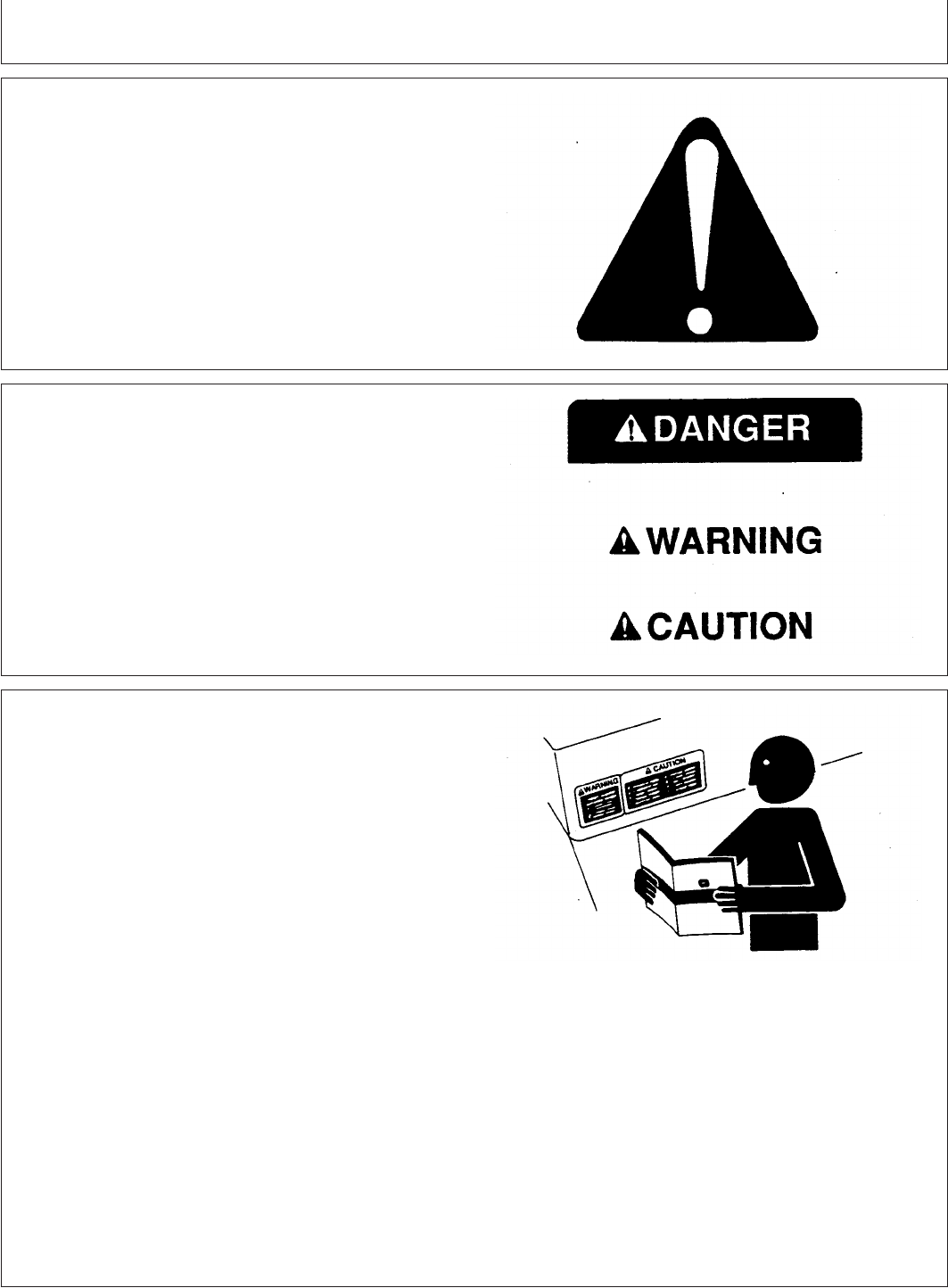
Recognize Safety Information
T81389 –UN–07DEC88
This is a safety-alert symbol. When you see this symbol
on your machine or in this manual, be alert to the
potential for personal injury.
Follow recommended precautions and safe operating
practices.
DX,SIGNAL –19–03MAR93–1/1
Understand Signal Words
TS187 –19–30SEP88
A signal word—DANGER, WARNING, or CAUTION—is
used with the safety-alert symbol. DANGER identifies the
most serious hazards.
DANGER or WARNING safety signs are located near
specific hazards. General precautions are listed on
CAUTION safety signs. CAUTION also calls attention to
safety messages in this manual.
DX,READ –19–03MAR93–1/1
Follow Safety Instructions
TS201 –UN–23AUG88
Carefully read all safety messages in this manual and on
your machine safety signs. Keep safety signs in good
condition. Replace missing or damaged safety signs. Be
sure new equipment components and repair parts include
the current safety signs. Replacement safety signs are
available from your John Deere dealer.
Learn how to operate the machine and how to use
controls properly. Do not let anyone operate without
instruction.
Keep your machine in proper working condition.
Unauthorized modifications to the machine may impair the
function and/or safety and affect machine life.
If you do not understand any part of this manual and need
assistance, contact your John Deere dealer.
05-1
082206
PN=7
Safety
CED,OUO1032,2778 –19–15OCT99–1/1
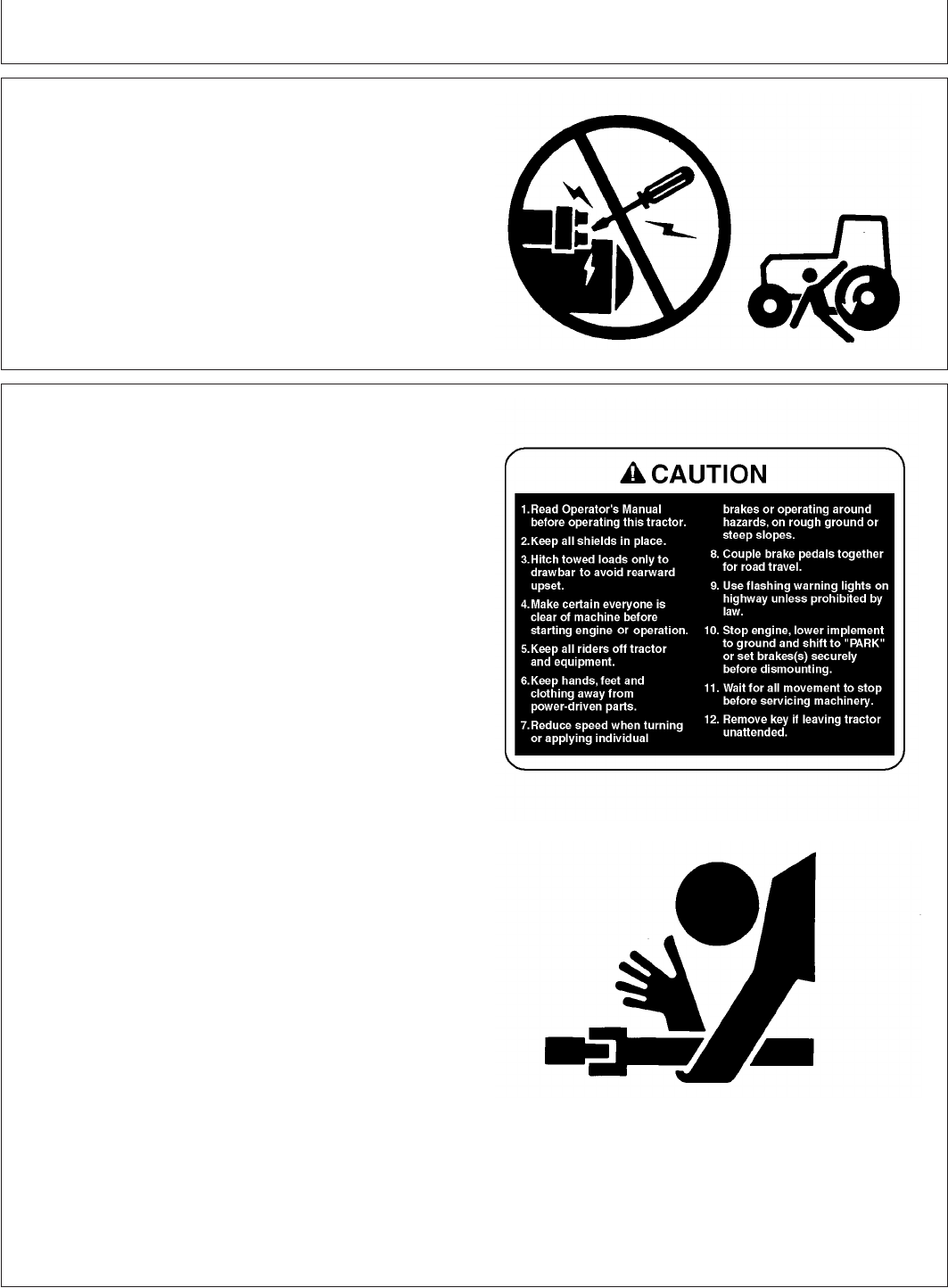
Prevent Machine Runaway
TS177 –UN–11JAN89
Avoid possible injury or death from machinery runaway.
Do not start engine by shorting across starter terminals.
Machine will start in gear if normal circuitry is bypassed.
NEVER start engine while standing on ground. Start
engine only from operator’s seat, with transmission in
neutral.
AG,OUO6035,84 –19–18MAY00–1/1
Operate Tractor Safely
M47224A –19–02JUN97
TS276 –UN–23AUG88
Features designed into your tractor make operation safer
and let it perform a wide variety of jobs. Use your tractor
only for specified jobs it was designed to perform:
implement carrier, load mover, remote power source, or
transport unit—not a recreational vehicle.
Careless use or misuse can result in unnecessary
accidents. Be alert to hazards of tractor operation.
Understand causes of accidents and take every
precaution to avoid them. Most common accidents are
caused from:
•Tractor upsets
•Improper starting procedures
•Crushing and pinching during hitching
•Collisions with other motor vehicles
•Getting entangled in PTO shafts
•Falls from tractors
Avoid accidents by taking the following precautions:
•Put the gear lever in Park position. Leaving
transmission in gear with engine stopped will NOT
prevent the tractor from moving.
•Be sure everyone is clear of tractor and attached
equipment before starting engine.
•Never try to get on or off a moving tractor.
•When tractor is left unattended, put the gear lever in
Park position , stop the engine , remove the key, lower
implements to the ground.
05-2
082206
PN=8
Safety
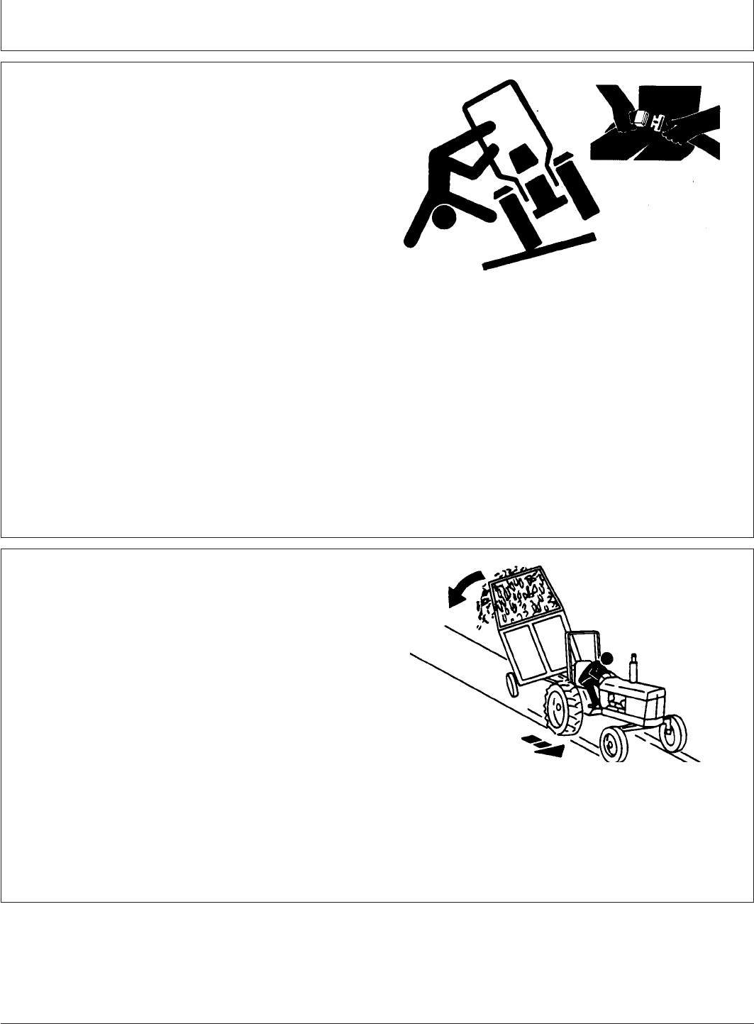
AG,OUO6035,65 –19–17MAY00–1/1
Use Caution on Hillsides
TS205 –UN–23AUG88
Avoid holes, ditches, and obstructions which cause the
tractor to tip, especially on hillsides. Avoid sharp, uphill
turns.
Never drive near the edge of a gully or steep
embankment -- it might cave in.
Driving forward out of a ditch or mired condition or up a
steep slope could cause tractor to tip over rearward. Back
out of these situations if possible.
Danger of overturn increases greatly with narrow tread
setting, at high speed.
Hitch towed loads only to drawbar. When using a chain,
take up the slack slowly.
AG,OUO6035,83 –19–17MAY00–1/1
Shift to Low Gear on Hills
LV4042 –UN–09JUL99
Shift to a low gear before descending a steep hill to
improve your control of the tractor with little or no braking.
Use engine braking to reduce speed before applying
tractor brakes. Run-away tractors often tip over. Never
coast downhill.
When driving on icy, wet or oily surfaces, reduce speed
and be sure tractor is properly ballasted (specially front
tyres)to avoid skidding and loss of steering control.
Additional ballast may be needed for transporting heavy
hitch mounted implements. When implement is raised,
drive slowly over rough ground, regardless of how much
ballast is used.
05-3
082206
PN=9

Safety
MX,AVOIDTIP1A1 –19–22JUL94–1/1
Avoid Tipping
TS205 –UN–23AUG88
Do not drive where machine could slip or tip.
Stay alert for holes, rocks, and roots in the terrain, and
other hidden hazards. Keep away from drop-offs.
Slow down before you make a sharp turn.
Take care when pulling loads or using heavy equipment:
•Use only approved drawbar hitch points.
•Limit loads to those you can safely control.
•Use counterweights or wheel weights when suggested
in this operator’s manual.
Reduce speed and exercise extreme caution on slopes
and in sharp turns to prevent tipping or loss of control. Be
especially cautious when changing direction on slopes.
Do not stop or start suddenly when going uphill or
downhill.
If machine stops going up hill:
•STOP the PTO.
•Back down slowly.
05-4
082206
PN=10
Safety
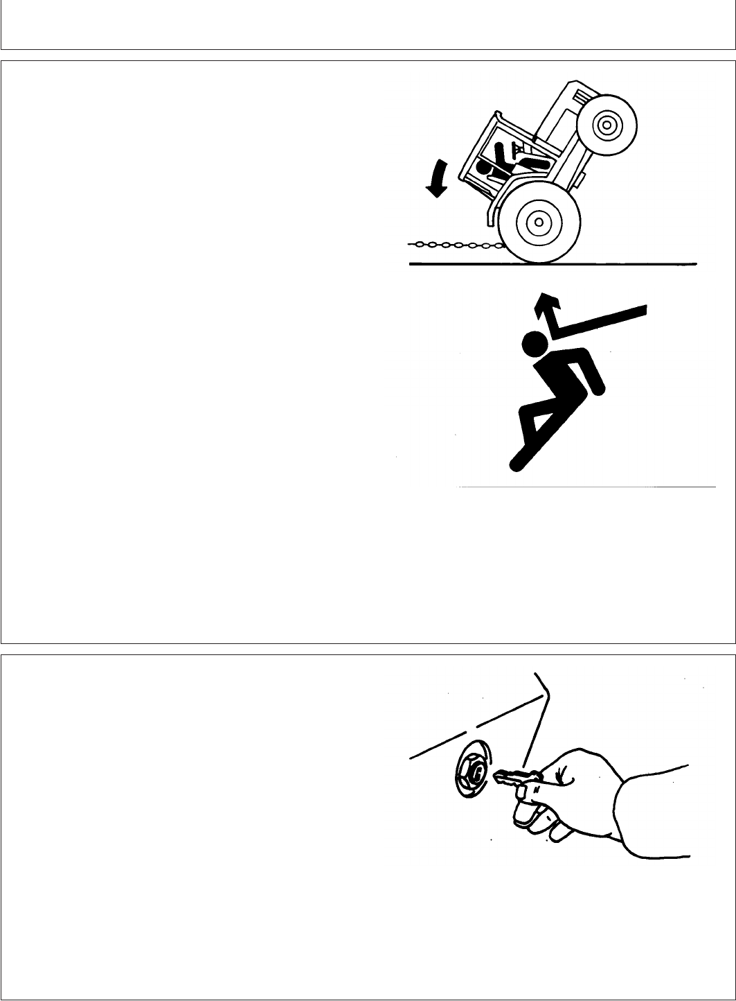
DX,MIRED –19–07JUL99–1/1
Freeing a Mired Machine
TS1645 –UN–15SEP95TS263 –UN–23AUG88
Attempting to free a mired machine can involve safety
hazards such as the mired tractor tipping rearward, the
towing tractor overturning, and the tow chain or tow bar (a
cable is not recommended) failing and recoiling from its
stretched condition.
Back your tractor out if it gets mired down in mud. Unhitch
any towed implements. Dig mud from behind the rear
wheels. Place boards behind the wheels to provide a solid
base and try to back out slowly. If necessary, dig mud
from the front of all wheels and drive slowly ahead.
If necessary to tow with another unit, use a tow bar or a
long chain (a cable is not recommended). Inspect the
chain for flaws. Make sure all parts of towing devices are
of adequate size and strong enough to handle the load.
Always hitch to the drawbar of the towing unit. Do not
hitch to the front pushbar attachment point. Before
moving, clear the area of people. Apply power smoothly to
take up the slack: a sudden pull could snap any towing
device causing it to whip or recoil dangerously.
MX,SAIP,AAA1 –19–21AUG99–1/1
Park Tractor Safely
M35691 –UN–26APR89
To park tractor safely:
•Disengage PTO.
•Lower equipment to the ground.
•Put gear shift lever in PARK.
•STOP the engine.
•Remove key.
Before you leave the operator’s seat, wait for engine and
attachment parts to stop moving.
05-5
082206
PN=11
Safety
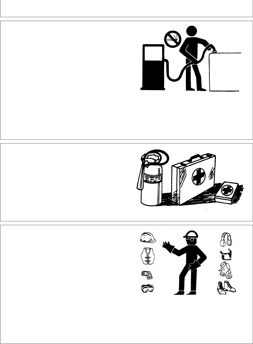
DX,FIRE1 –19–03MAR93–1/1
Handle Fuel Safely—Avoid Fires
TS202 –UN–23AUG88
Handle fuel with care: it is highly flammable. Do not refuel
the machine while smoking or when near open flame or
sparks.
Always stop engine before refueling machine. Fill fuel tank
outdoors.
Prevent fires by keeping machine clean of accumulated
trash, grease, and debris. Always clean up spilled fuel.
DX,FIRE2 –19–03MAR93–1/1
Prepare for Emergencies
TS291 –UN–23AUG88
Be prepared if a fire starts.
Keep a first aid kit and fire extinguisher handy.
Keep emergency numbers for doctors, ambulance service,
hospital, and fire department near your telephone.
DX,WEAR –19–10SEP90–1/1
Wear Protective Clothing
TS206 –UN–23AUG88
Wear close fitting clothing and safety equipment
appropriate to the job.
Prolonged exposure to loud noise can cause impairment
or loss of hearing.
Wear a suitable hearing protective device such as
earmuffs or earplugs to protect against objectionable or
uncomfortable loud noises.
Operating equipment safely requires the full attention of
the operator. Do not wear radio or music headphones
while operating machine.
05-6
082206
PN=12
Safety
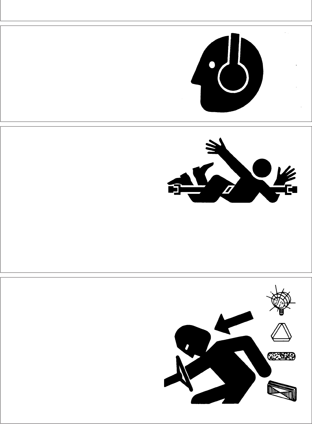
DX,NOISE –19–03MAR93–1/1
Protect Against Noise
TS207 –UN–23AUG88
Prolonged exposure to loud noise can cause impairment
or loss of hearing.
Wear a suitable hearing protective device such as
earmuffs or earplugs to protect against objectionable or
uncomfortable loud noises.
DX,PTO –19–12SEP95–1/1
Stay Clear of Rotating Drivelines
TS1644 –UN–22AUG95
Entanglement in rotating driveline can cause serious injury
or death.
Keep tractor master shield and driveline shields in place
at all times. Make sure rotating shields turn freely.
Wear close fitting clothing. Stop the engine and be sure
PTO driveline is stopped before making adjustments,
connections, or cleaning out PTO driven equipment.
DX,FLASH –19–07JUL99–1/1
Use Safety Lights and Devices
TS951 –UN–12APR90
Prevent collisions between other road users, slow moving
tractors with attachments or towed equipment, and
self-propelled machines on public roads. Frequently check
for traffic from the rear, especially in turns, and use turn
signal lights.
Use headlights, flashing warning lights, and turn signals
day and night. Follow local regulations for equipment
lighting and marking. Keep lighting and marking visible,
clean, and in good working order. Replace or repair
lighting and marking that has been damaged or lost. An
implement safety lighting kit is available from your John
Deere dealer.
05-7
082206
PN=13
Safety
MX,SAIP,LA1 –19–29JUL94–1/1
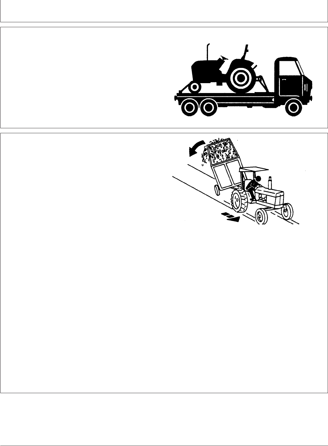
Safely Transporting the Tractor
LV610 –UN–22APR94
A disabled tractor is best transported on a flatbed carrier.
Use chains to secure the tractor to the carrier.
Never tow a tractor at a speed greater than 16 km/h (10
mph). An operator must steer and brake the tractor under
tow.
DX,TOW –19–02OCT95–1/1
Tow Loads Safely
TS216 –UN–23AUG88
Stopping distance increases with speed and weight of
towed loads, and on slopes. Towed loads with or without
brakes that are too heavy for the tractor or are towed too
fast can cause loss of control. Consider the total weight of
the equipment and its load.
Observe these recommended maximum road speeds, or
local speed limits which may be lower:
•If towed equipment does not have brakes, do not travel
more than 32 km/h (20 mph) and do not tow loads more
than 1.5 times the tractor weight.
•If towed equipment has brakes, do not travel more than
40 km/h (25 mph) and do not tow loads more than 4.5
times the tractor weight.
Ensure the load does not exceed the recommended
weight ratio. Add ballast to recommended maximum for
tractor, lighten the load, or get a heavier towing unit. The
tractor must be heavy and powerful enough with adequate
braking power for the towed load. Use additional caution
when towing loads under adverse surface conditions,
when turning, and on inclines.
05-8
082206
PN=14
Safety
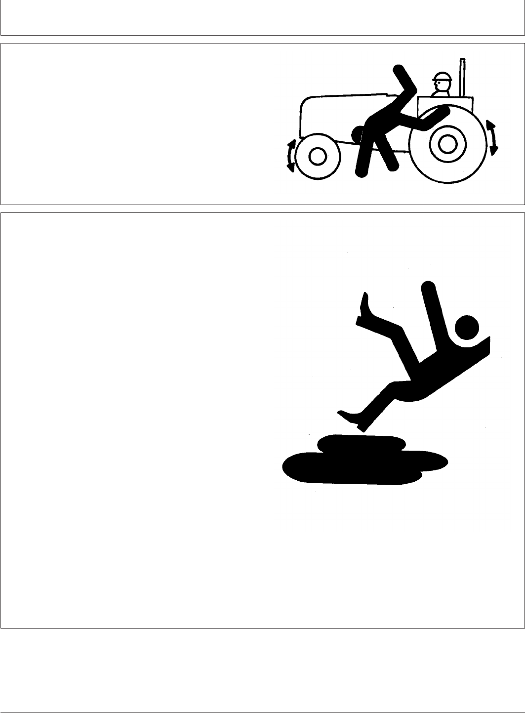
DX,RIDER –19–03MAR93–1/1
Keep Riders Off Machine
TS290 –UN–23AUG88
Only allow the operator on the machine. Keep riders off.
Riders on machine are subject to injury such as being
struck by foreign objects and being thrown off of the
machine. Riders also obstruct the operator’s view resulting
in the machine being operated in an unsafe manner.
DX,SERV –19–17FEB99–1/1
Practice Safe Maintenance
TS218 –UN–23AUG88
Understand service procedure before doing work. Keep
area clean and dry.
Never lubricate, service, or adjust machine while it is
moving. Keep hands, feet , and clothing from
power-driven parts. Disengage all power and operate
controls to relieve pressure. Lower equipment to the
ground. Stop the engine. Remove the key. Allow machine
to cool.
Securely support any machine elements that must be
raised for service work.
Keep all parts in good condition and properly installed. Fix
damage immediately. Replace worn or broken parts.
Remove any buildup of grease, oil, or debris.
On self-propelled equipment, disconnect battery ground
cable (-) before making adjustments on electrical systems
or welding on machine.
On towed implements, disconnect wiring harnesses from
tractor before servicing electrical system components or
welding on machine.
05-9
082206
PN=15
Safety
AG,OUO6035,70 –19–17MAY00–1/1
Service Tractor Safely
LV828 –UN–08AUG94
Do not service the tractor while it is in motion or while the
engine is running.
Tighten wheel hardware to correct torque as specified in
Wheels, Tyres and Tread section. Torque at intervals
shown in Break-In Period and Lubrication and
Maintenance sections, to ensure that wheel hardware
does not loosen.
Reinstall shields removed during service.
DX,AIR –19–17FEB99–1/1
Work In Ventilated Area
TS220 –UN–23AUG88
Engine exhaust fumes can cause sickness or death. If it is
necessary to run an engine in an enclosed area, remove
the exhaust fumes from the area with an exhaust pipe
extension.
If you do not have an exhaust pipe extension, open the
doors and get outside air into the area
DX,LOWER –19–24FEB00–1/1
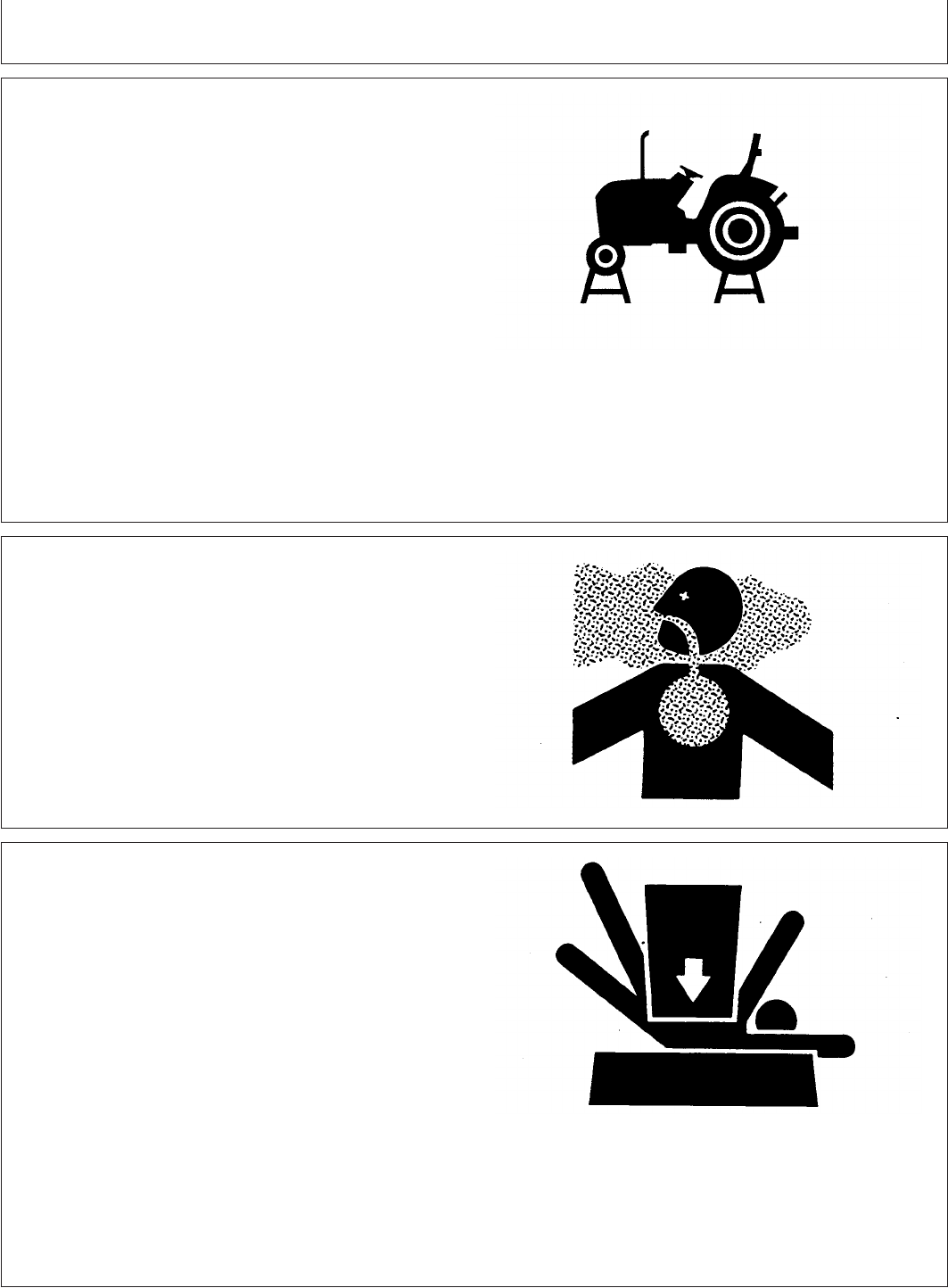
Support Machine Properly
TS229 –UN–23AUG88
Always lower the attachment or implement to the ground
before you work on the machine. If the work requires that
the machine or attachment be lifted, provide secure
support for them. If left in a raised position, hydraulically
supported devices can settle or leak down.
Do not support the machine on cinder blocks, hollow tiles,
or props that may crumble under continuous load. Do not
work under a machine that is supported solely by a jack.
Follow recommended procedures in this manual.
When implements or attachments are used with a
machine, always follow safety precautions listed in the
implement or attachment operator’s manual.
05-10
082206
PN=16
Safety
DX,TORCH –19–10DEC04–1/1
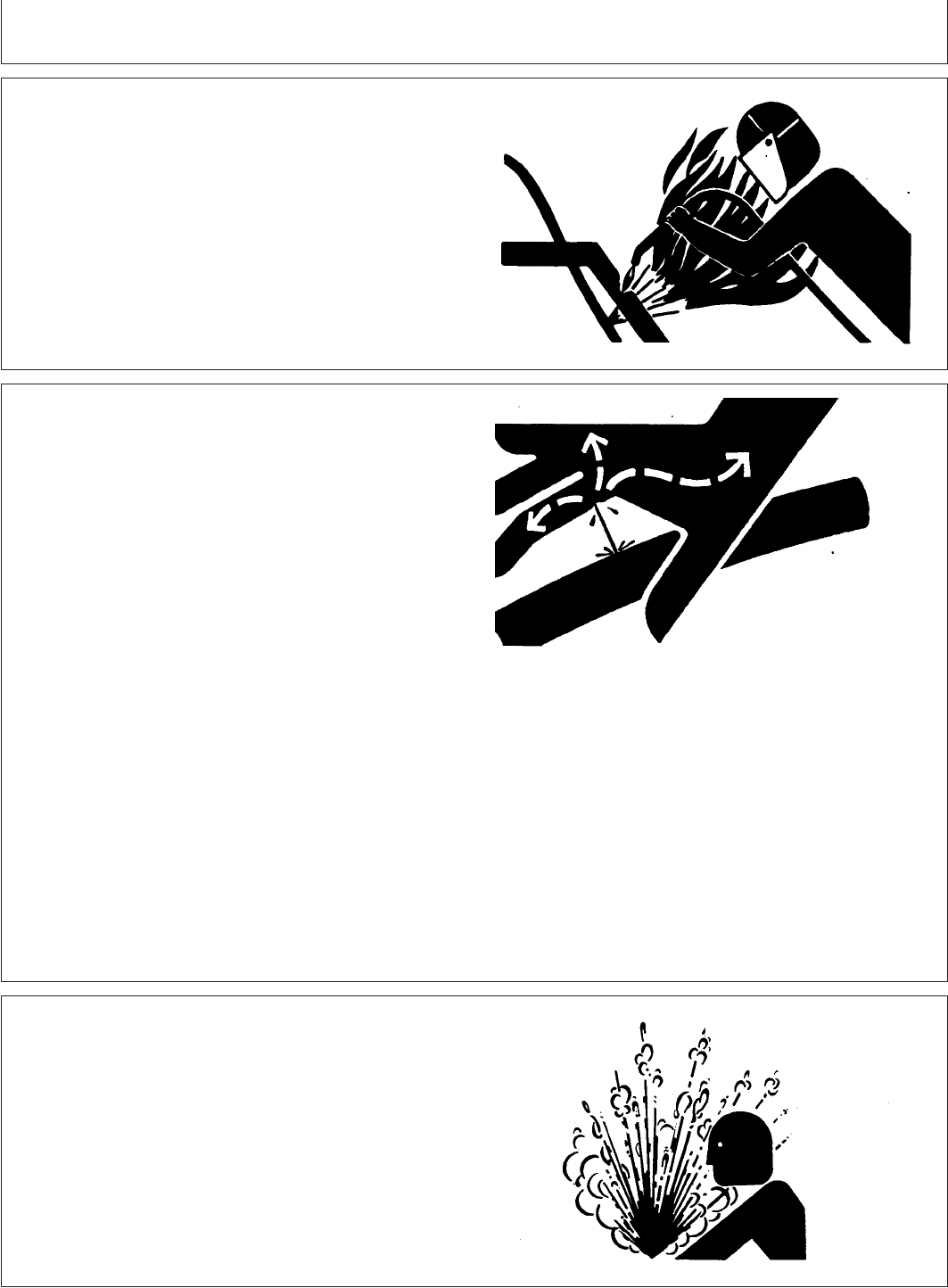
Avoid Heating Near Pressurized Fluid Lines
TS953 –UN–15MAY90
Flammable spray can be generated by heating near
pressurized fluid lines, resulting in severe burns to
yourself and bystanders. Do not heat by welding,
soldering, or using a torch near pressurized fluid lines or
other flammable materials. Pressurized lines can
accidentally burst when heat goes beyond the immediate
flame area.
DX,FLUID –19–03MAR93–1/1
Avoid High-Pressure Fluids
X9811 –UN–23AUG88
Escaping fluid under pressure can penetrate the skin
causing serious injury.
Avoid the hazard by relieving pressure before
disconnecting hydraulic or other lines. Tighten all
connections before applying pressure.
Search for leaks with a piece of cardboard. Protect hands
and body from high pressure fluids.
If an accident occurs, see a doctor immediately. Any fluid
injected into the skin must be surgically removed within a
few hours or gangrene may result. Doctors unfamiliar with
this type of injury should reference a knowledgeable
medical source. Such information is available from Deere
& Company Medical Department in Moline, Illinois, U.S.A.
AG,OUO1032,2682 –19–30SEP99–1/1
Service Cooling System Safely
TS281 –UN–23AUG88
Explosive release of fluids from pressurized cooling
system can cause serious burns.
If radiator cap must be removed, do not remove when
engine is hot. Shut engine off and wait until cap is cool
enough to touch with bare hands. Slowly loosen cap to
first stop to relieve pressure before removing completely.
05-11
082206
PN=17
Safety
DX,STORE –19–03MAR93–1/1
Store Attachments Safely
TS219 –UN–23AUG88
Stored attachments such as dual wheels, cage wheels,
and loaders can fall and cause serious injury or death.
Securely store attachments and implements to prevent
falling. Keep playing children and bystanders away from
storage area.
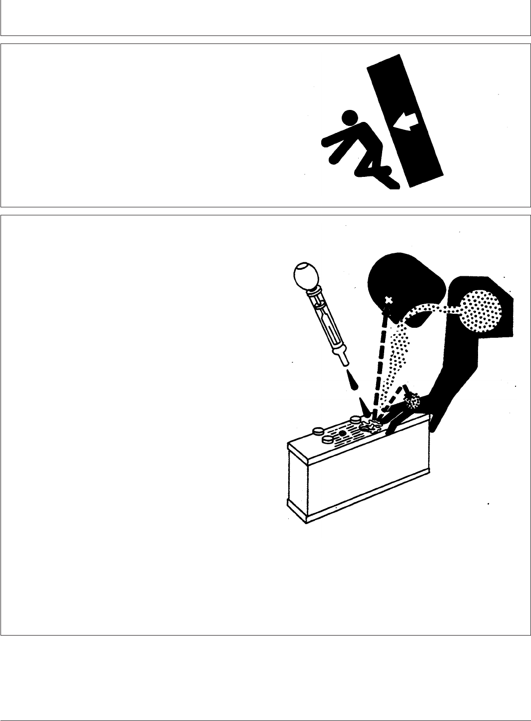
DX,POISON –19–21APR93–1/1
Prevent Acid Burns
TS203 –UN–23AUG88
Sulfuric acid in battery electrolyte is poisonous. It is strong
enough to burn skin, eat holes in clothing, and cause
blindness if splashed into eyes.
Avoid the hazard by:
1. Filling batteries in a well-ventilated area.
2. Wearing eye protection and rubber gloves.
3. Avoiding breathing fumes when electrolyte is added.
4. Avoiding spilling or dripping electrolyte.
5. Use proper jump start procedure.
If you spill acid on yourself:
1. Flush your skin with water.
2. Apply baking soda or lime to help neutralize the acid.
3. Flush your eyes with water for 15—30 minutes. Get
medical attention immediately.
If acid is swallowed:
1. Do not induce vomiting.
2. Drink large amounts of water or milk, but do not
exceed2L(2quarts).
3. Get medical attention immediately.
05-12
082206
PN=18
Safety
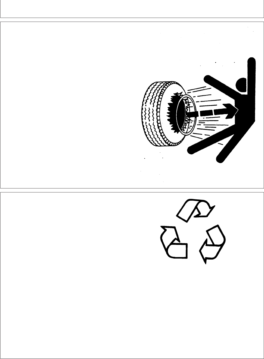
DX,RIM –19–24AUG90–1/1
Service Tires Safely
TS211 –UN–23AUG88
Explosive separation of a tire and rim parts can cause
serious injury or death.
Do not attempt to mount a tire unless you have the proper
equipment and experience to perform the job.
Always maintain the correct tire pressure. Do not inflate
the tires above the recommended pressure. Never weld or
heat a wheel and tire assembly. The heat can cause an
increase in air pressure resulting in a tire explosion.
Welding can structurally weaken or deform the wheel.
When inflating tires, use a clip-on chuck and extension
hose long enough to allow you to stand to one side and
NOT in front of or over the tire assembly. Use a safety
cage if available.
Check wheels for low pressure, cuts, bubbles, damaged
rims or missing lug bolts and nuts.
AG,OUO1032,2683 –19–30SEP99–1/1
Dispose of Waste Properly
TS1133 –UN–26NOV90
Improperly disposing of waste can threaten the
environment and ecology. Potentially harmful waste used
with John Deere equipment include such items as oil, fuel,
coolant, brake fluid, filters, and batteries.
Use leakproof containers when draining fluids. Do not use
food or beverage containers that may mislead someone
into drinking from them.
Do not pour waste onto the ground, down a drain, or into
any water source.
Inquire on the proper way to recycle or dispose of waste
from your local environmental or recycling center, or from
your John Deere dealer.
05-13
082206
PN=19
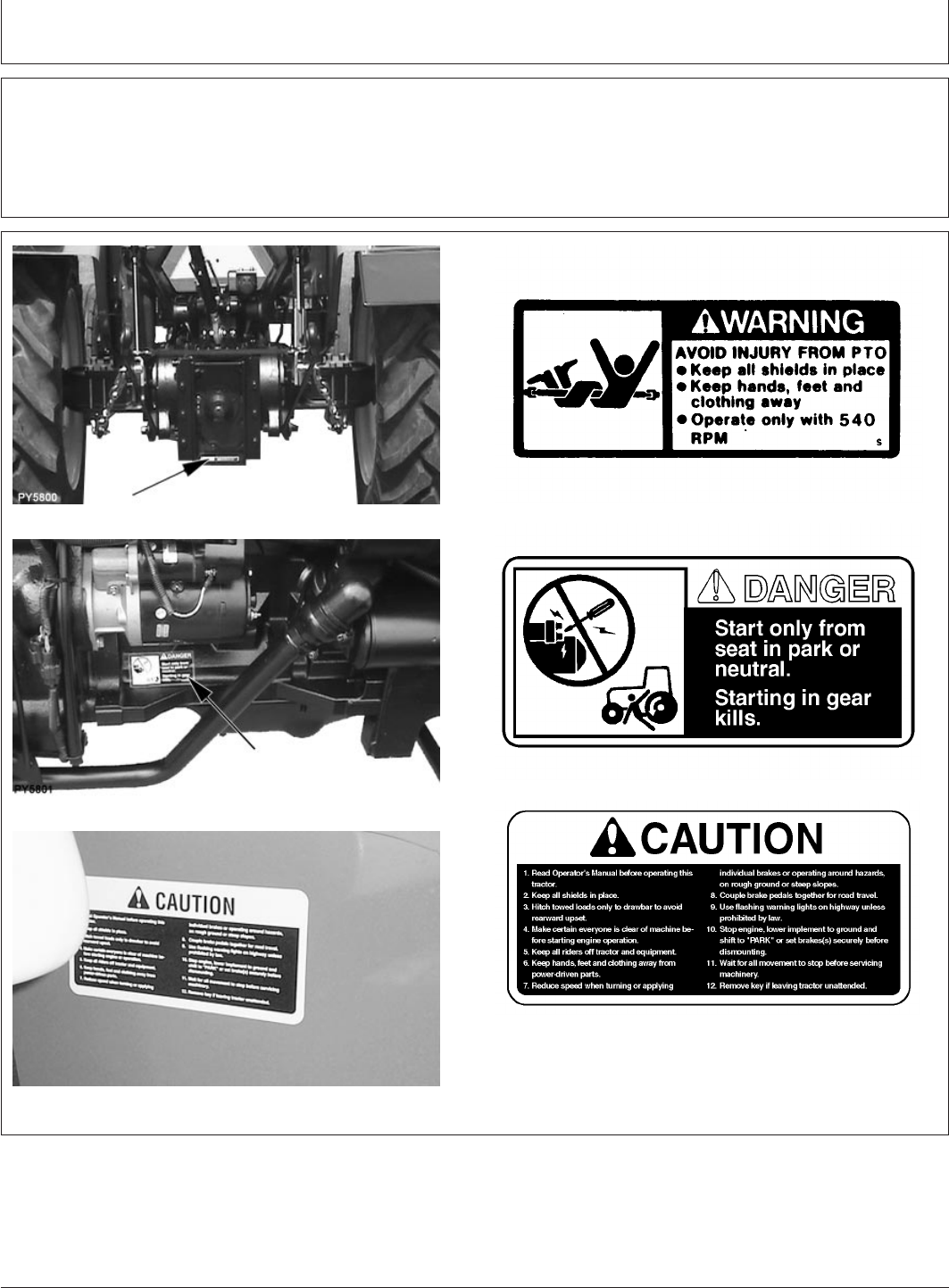
Safety Signs
GENERIC,0000038 –19–28JUN06–1/4
Warning Labels
Keep warning labels in good condition, replace if not in
readable condition.
GENERIC,0000038 –19–28JUN06–2/4
PY5800 –UN–11JUL06
Top surface of PTO shield
M71026 –19–02JUL90
PY5801 –UN–11JUL06
Just below starter body
LV1932 –19–02JUN97
PY1057 –UN–25JUN01
Left fender
LV4307 –19–04NOV05
Continued on next page
10-1
082206
PN=20
Safety Signs
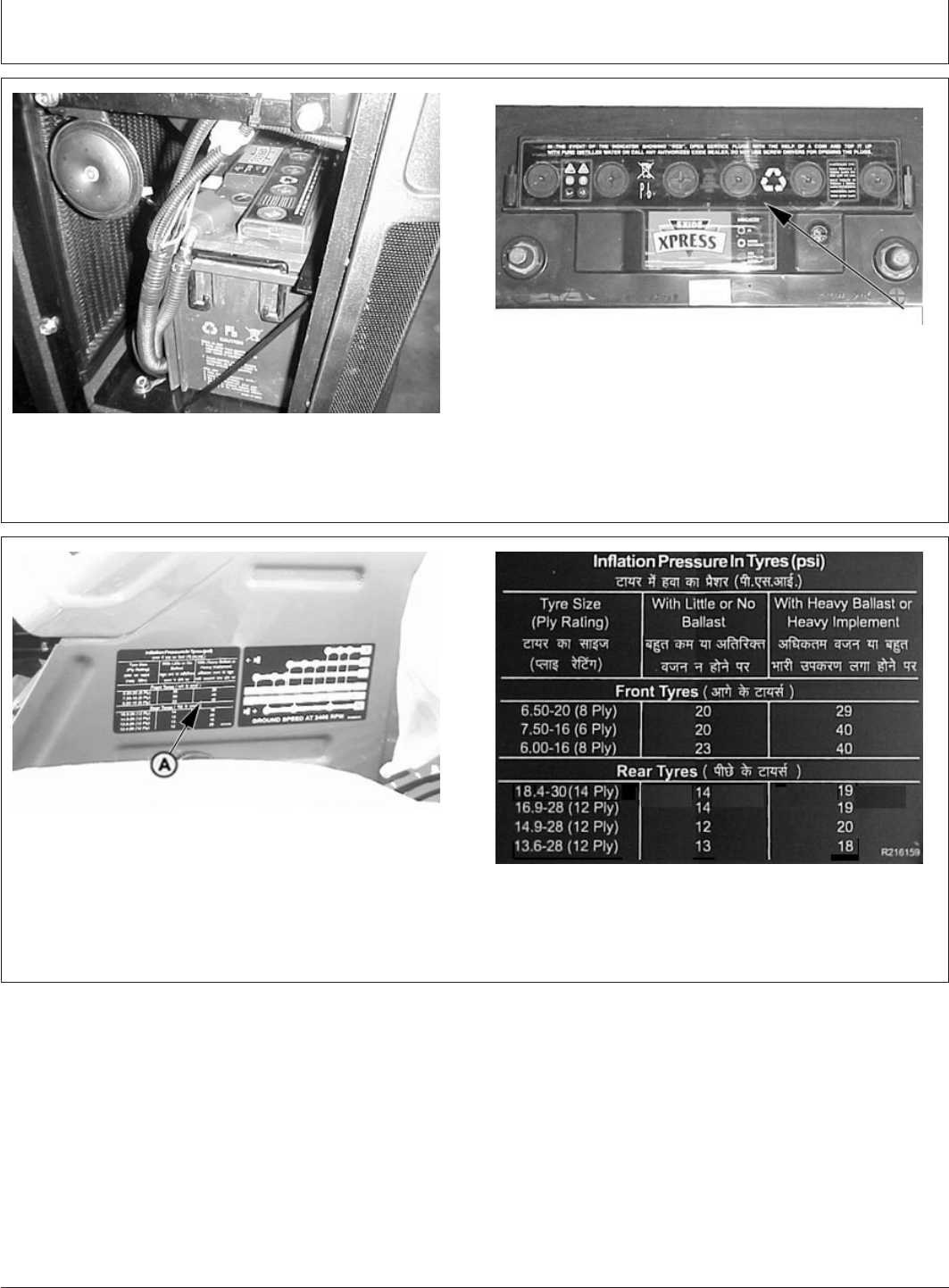
GENERIC,0000038 –19–28JUN06–3/4
PY1965 –UN–24FEB04
Top of Battery
PY2280 –UN–18NOV04
GENERIC,0000038 –19–28JUN06–4/4
PY4879 –UN–06DEC05
Right Fender
PY4342 –UN–29DEC04
Right Fender
10-2
082206
PN=21
Controls and Instruments
PY80265,05I0102 –19–17FEB06–1/2
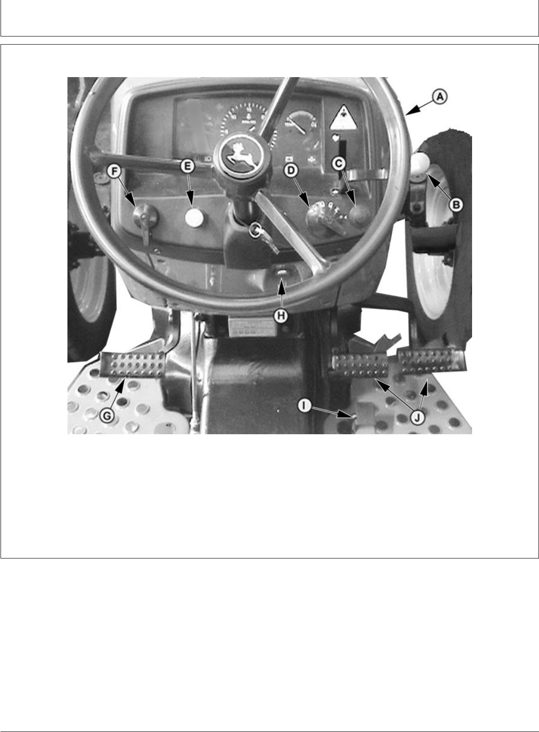
Tractor Controls
PY5158 –UN–17FEB06
A—Steering Wheel D—Light Switch G—Clutch Pedal I—Foot Throttle
B—Hand Throttle E—Hazard Switch H—Key Switch J—Brake Pedal
C—Horn Button F—Turn Signal Switch
Continued on next page
15-1
082206
PN=22
Controls and Instruments
PY80265,05I0102 –19–17FEB06–2/2
PY5501 –UN–16FEB06
PY5544 –UN–06MAR06
PY4077 –UN–19JAN06
.
PY4542 –UN–26JAN05
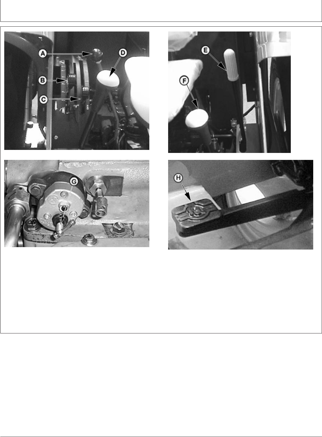
A—Selective Control Lever C—Rockshaft Draft Control E—PTO Shift Lever H—Differential Lock Pedals
B—Rockshaft Position Control Lever F—Range Shift Lever
Lever D—Gear Shift Lever G—Rockshaft Rate-of- drop
Knob
15-2
082206
PN=23
Controls and Instruments
PY80265,05I0105 –19–12SEP05–1/1
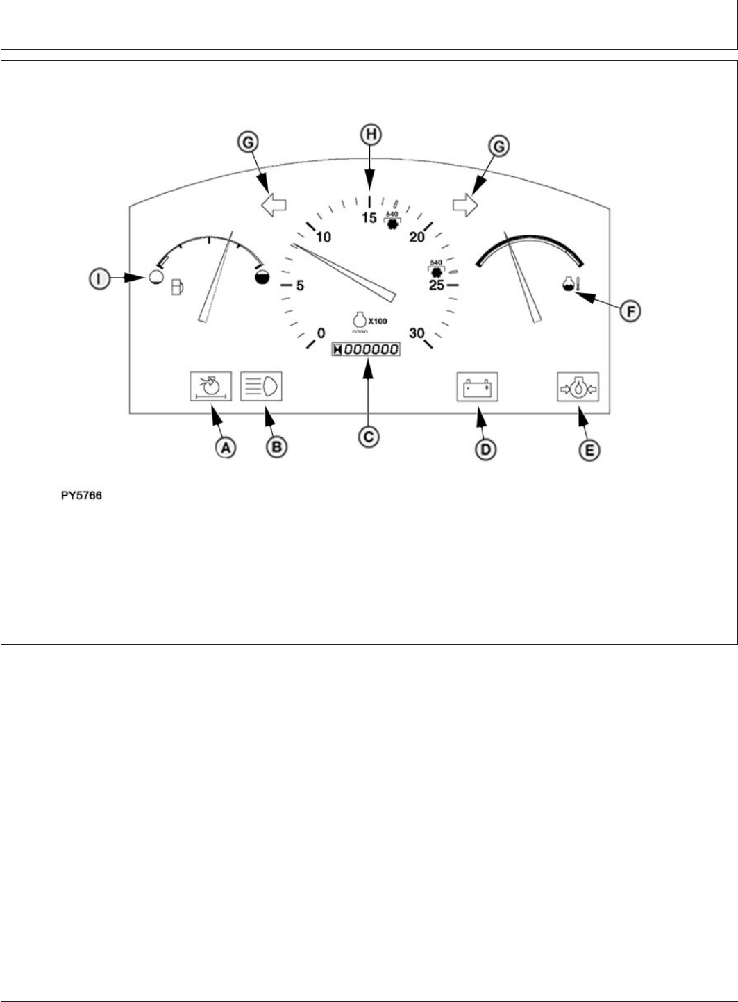
Instrument Panel
PY5766 –UN–02JUN06
A—Air Restriction Indicator D—Charging System Indicator F—Coolant Temperature H—Tachometer
B—High Beam Indicator E—Engine Oil Pressure Gauge I—Fuel Gauge
C—Hour Meter Indicator G—Turn Signal Direction
Indicators
15-3
082206
PN=24
Lights
GENERIC,000003A –19–11JUL06–1/1
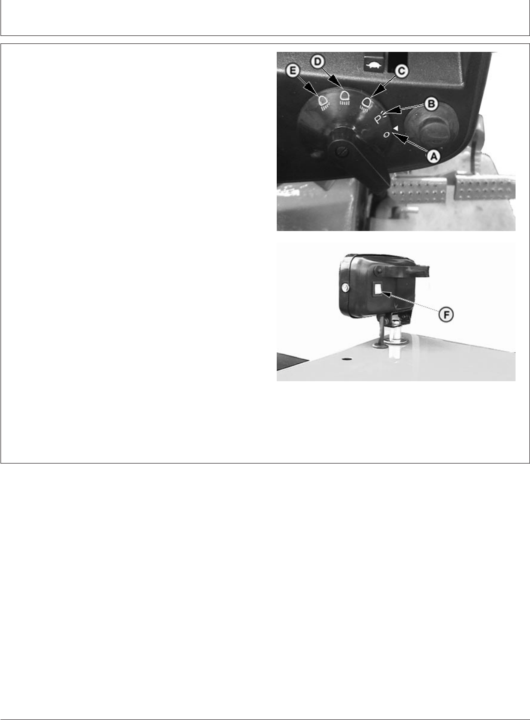
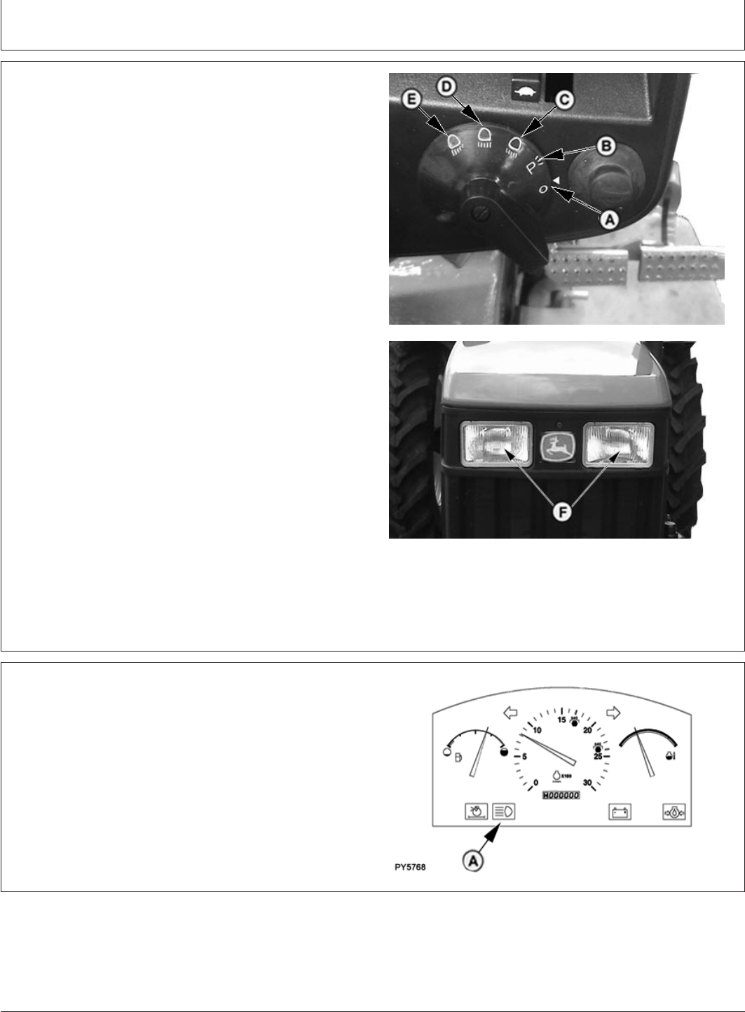
Light Switch Positions
PY4481 –UN–11JAN05PY4107 –UN–21AUG04
A—Lights Off
B—Warning Lights Position
C—Dim Headlights,Tail Lights and Warning Light
Position
D—Bright Headlights, Tail Lights and Warning Lights
Position
E—High Beamlights
F—Flood Light Switch
Tractor light switch has five positions:
A—Turns off all lights.
B—Turns on warning lights only. Use for parking the
vehicle
C—Turns on dim headlights, tail lights and warning lights.
Turn switch to this position before meeting other vehicles.
D—Turns on bright headlights, tail lights and warning
lights. For highway driving during night time
E—Turns on high beamlight.
F— Switch on flood light (plough lamp). for field use only.
Do not use on roads. Flood light might blind or confuse
other drivers.
20-1
082206
PN=25
Lights
GENERIC,000003B –19–11JUL06–1/1
Using Headlights
PY4481 –UN–11JAN05
PY5148 –UN–23FEB06
A—Lights Off
B—Warning Lights Position
C—Dim Headlights, Tail Lights, and Warning Light
Position
D—Bright Headlights, Tail Lights and Warning Lights
Position
E—High Beamlight
F—Headlights
Dual-beam headlights (F) are switched on by either “High
Beamlight” (E), “Bright Headlight” (D), or “Dim Headlight”
(C) light switch positions.
Always dim lights before meeting another vehicle.
Keep headlights adjusted properly, (see Adjusting
Headlights in Service section).
PY80265,05I0108 –19–02JUN06–1/1
Using High Beam Indicator
PY5768 –UN–02JUN06
A—High Beam Indicator
High beam indicator (A) should glow when light switch is
turned to “Bright Headlight” position or “Flood Light”
position. Bright headlights, tail lights, flood light and
warning lights should be on.
20-2
082206
PN=26

Lights
PY80265,05I0109 –19–11JUL06–1/1
Using Tail Lights
PY4883 –UN–22APR05
A—Tail Lights
Red tail lights (A) are switched on by either bright
headlight or dim headlight light switch position.
Be sure tail light lenses are clean before driving on a
road, so other drivers can see it easily.
CAUTION: Prevent collisions between other
road users, slow moving tractors with
attachments or towed equipment, and
self-propelled machines on public roads.
Frequently check for traffic from the rear,
especially in turns, and use hand signals or
turn signal lights.
Use headlights, flashing warning lights, and
turn signals day and night. Follow local
regulations for equipment lighting and marking.
Keep lighting and marking visible and in good
working order. Replace or repair lighting and
marking that has been damaged or lost. An
implement safety lighting kit is available from
your John Deere dealer.
20-3
082206
PN=27
B—ReflexReflector
C—TurnSignalLights
Lights
GENERIC,000003D –19–11JUL06–1/1
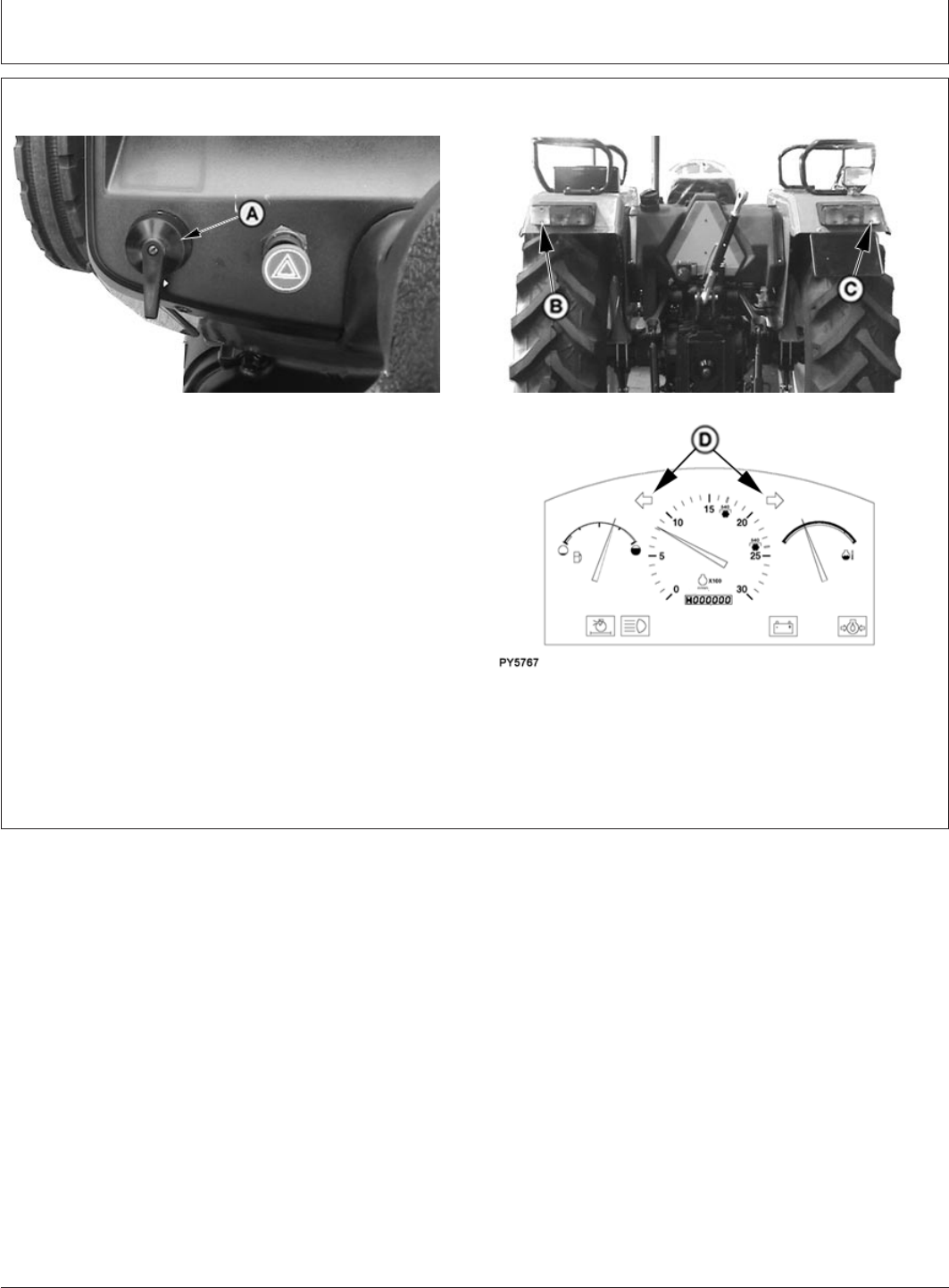
Using Turn Signals
PY4114 –UN–23FEB06
PY5510 –UN–17FEB06PY5767 –UN–02JUN06
A—Turn Signal Lever
B—Left-Hand Lights
C—Right-Hand Lights
D—Dash Indicator Lights
Move turn signal lever (A) down to indicate left-hand turn
or up for right-hand turn. Indicator lights (D) will flash to
signal turn direction.
When lever is up, front and rear turn lights on right-hand
side (C) will flash . When lever is down, front and rear turn
lights on left-hand side (B) will flash.
NOTE: Be sure to manually return lever to center position
after turning.
20-4
082206
PN=28
Lights
GENERIC,000003E –19–21FEB06–1/1
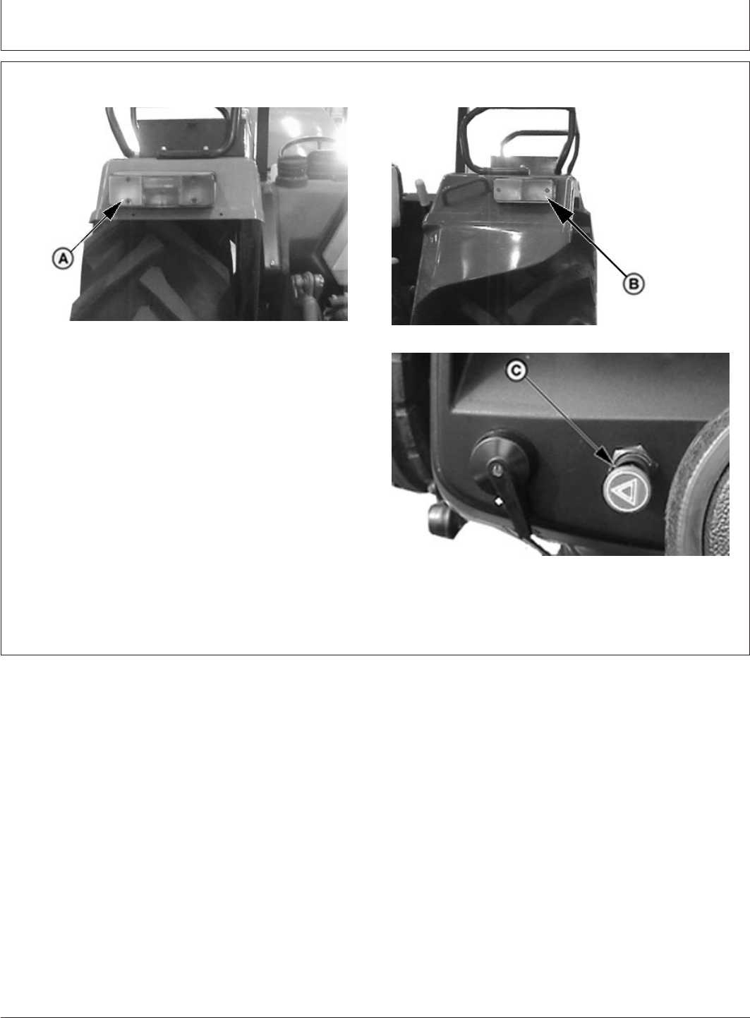
Using Hazard Lights
PY4338 –UN–28DEC04
Rear lights
PY4339 –UN–28DEC04
Front light
PY4896 –UN–20FEB06
Hazard Light Switch
A—Turn Signal Light on Rear Side
B— Turn Signal Light on Front Side
C— Hazard Light Switch
All 4 turn signal lights ( 2 front and 2 rear) start to blink
when hazard light switch (C) is pulled out. Use harzard
lights to warn approaching vehicles when tractor is
stopped on the road
20-5
082206
PN=29
Lights
PY80265,05I0112 –19–11JUL06–1/1
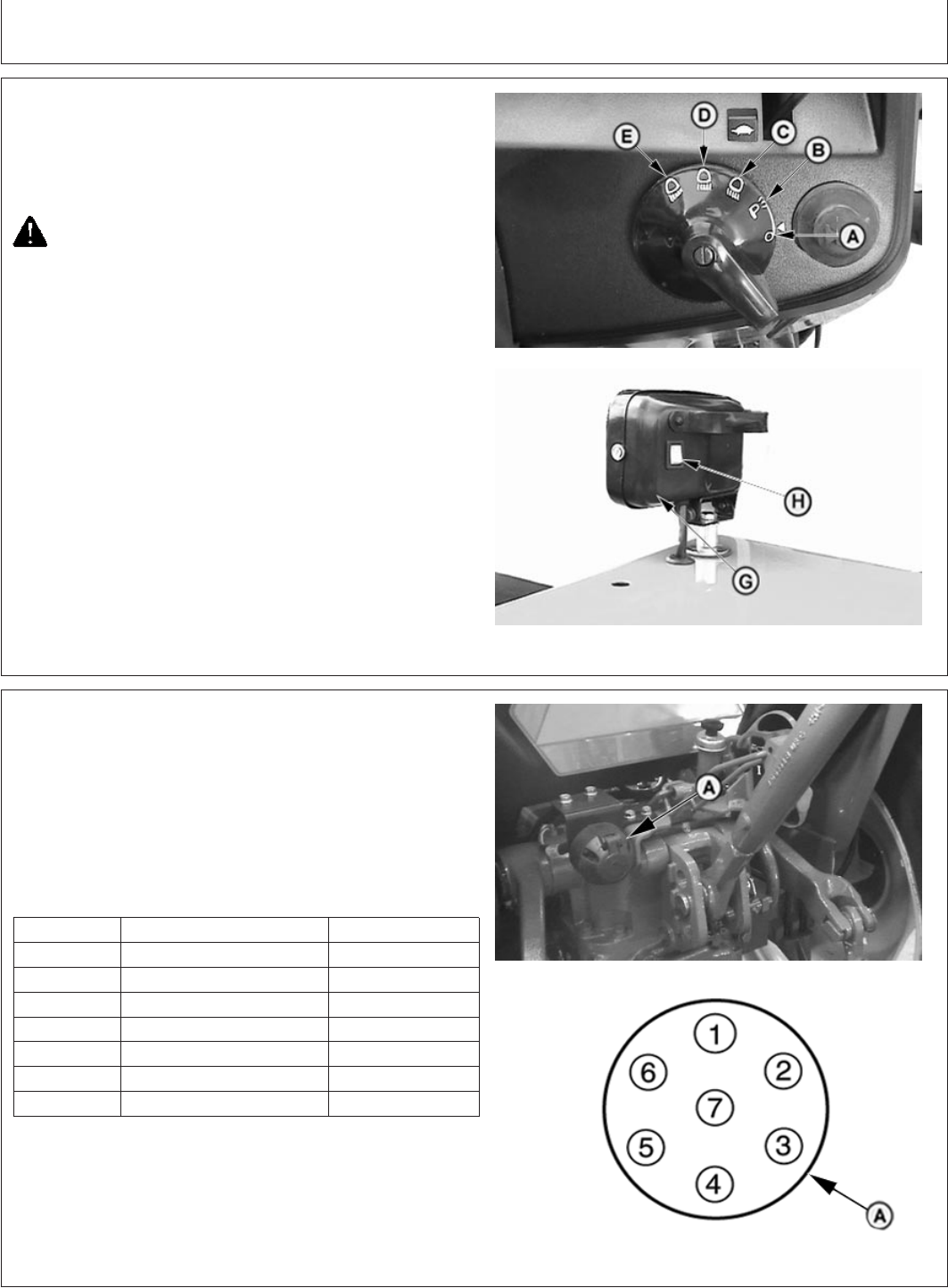
Using Flood Lamp
PY4106 –UN–23FEB06PY4150 –UN–20FEB06
A—Lights Off
B—Warning Lights Position
C—Dim Headlights, Tail Lights and Warning Light
Position
D—Bright Headlights, Tail Lights and Warning Lights
Position
E—High Beamlight
F—Horn
G—Flood Lamp
H—Flood Light Switch
Flood lamp (G) is switched on by “Flood Light (H)” switch
. Horn (F) is located just right-hand side of light switch
CAUTION: When operating on a road, move
light switch to either “Bright or Dim Head
Lamp” positions Never use flood lamp when
transporting. A clear, bright light at the rear of
the tractor could confuse drivers of other
vehicles as they approach from the rear.
GENERIC,0000053 –19–11JUL06–1/1
Seven-Terminal Outlet—If Equipped
PY5525 –UN–21FEB06PY5606 –UN–23FEB06
A—Seven-Terminal Outlet
Outlet (A) is used to connect lights, turn signals, and
remote electrical equipment on trailers or implements.
Always use auxiliary light on towed implement when
tractor rear signals and other lights are obscured.
NOTE: Matching plug is available through your John
Deere dealer.
Terminal Function Wire Color
1 Ground Black
2 Flood Lamp Purple
3 Left Turn Dark Green
4 Accessory Red
5 Right Turn Dark Green
6 Tail Lamp Gray
7 Accessory Red
20-6
082206
PN=30
Operator’sPlatform
PY80265,05I0114 –19–12SEP05–1/1
Selecting Seat Position
PY1032 –UN–24JUN01
A—Seat Adjustment Lever
Deluxe Seat
Seat can be moved forward or backward depending on
operator’s requirement. To move seat on either side, just
lift lever (A) and push the seat.
PY80265,05I0115 –19–12SEP05–1/1
Adjusting Ride Comfort
PY1033 –UN–24JUN01
A—Weight Adjustment Knob
Adjustment knob is located behind seat.
Weight markings are given on the rear of seat.Turn
adjustment knob (A) for a firm or soft ride. Seat
suspension will function properly relative to operator’s
weight.
25-1
082206
PN=31

Break-In Period
PY80265,05I0116 –19–02JUN06–1/1
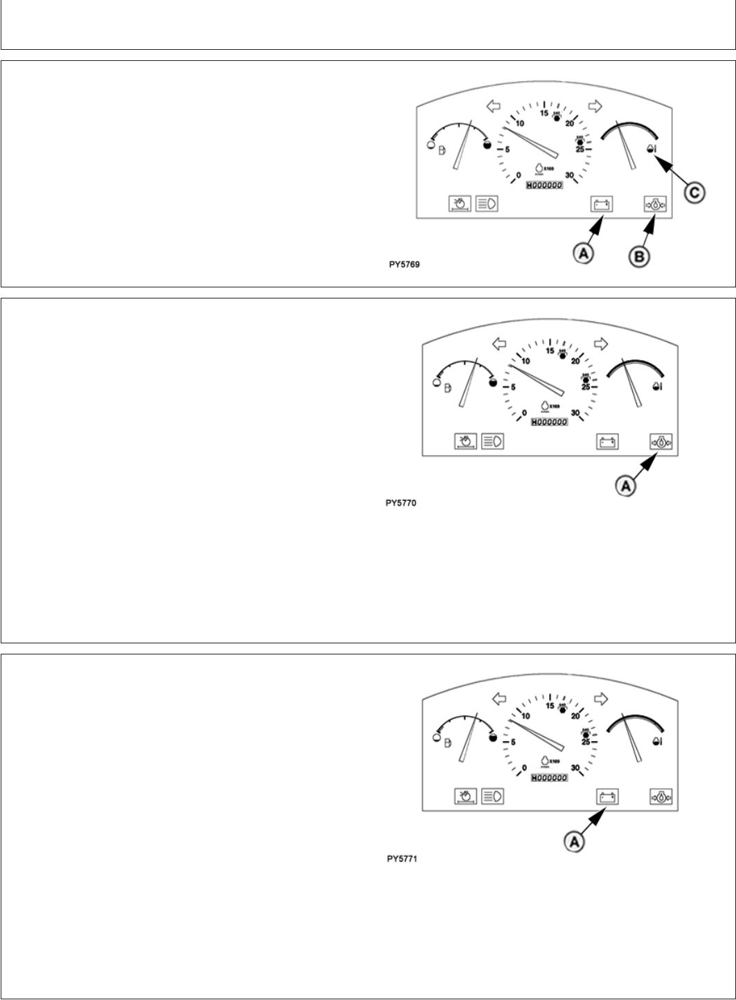
Observe Engine Operation Closely
PY5769 –UN–02JUN06
A—Charging Indicator
B—Oil Pressure Indicator
C—Coolant Temperature Indicator
IMPORTANT: The engine is ready for normal
operation. Be extra cautious during the
first 100 hours, until you become
thoroughly familiar with the sound and
feel of your new tractor. Stay extra
attentive and alert.
Warm up tractor carefully. Check charging (A) and oil
pressure (B) warning indicator lights and coolant
temperature gauge (C).
Avoid unnecessary engine idling.
Check engine oil, coolant, and transmission/hydraulic fluid
levels frequently. Watch for fluid leaks.
NOTE: If engine oil must be added, use seasonal
viscosity grade oil. Use only lubricants meeting
specifications given in the Fuels, Lubricants, and
Coolant section.
PY80265,05I0117 –19–12SEP05–1/1
Break-In Service
IMPORTANT: Keep wheel hardware tight to avoid
tractor damage. Check wheel
hardware torque before operating,
twice during first ten hours of
operation, after fifty hours of
operation, and periodically
thereafter.
During the First 10 Hours of Operation:
Perform daily or 10 hours service. (See Service
Intervals in Lubrication and Maintenance section)
Tighten wheel hardware. (See Wheels, Tyres, and
Treads section)
After the First 50 Hours of Operation:
Tighten wheel hardware. (See Wheels, Tyres, and
Treads section)
Check alternator/fan belt tension and tighten air intake
and cooling system hose clamps
Perform 50 Hours Service
After the First 100 Hours of Operation:
Replace transmission-hydraulic filter element
Change engine oil and filter
1
After the First 1100 Hours of Operation:
Change transmission-hydraulic oil
1
See Engine Break-In Oil in Service section for additional
information.
35-1
082206
PN=32
Prestarting Checks
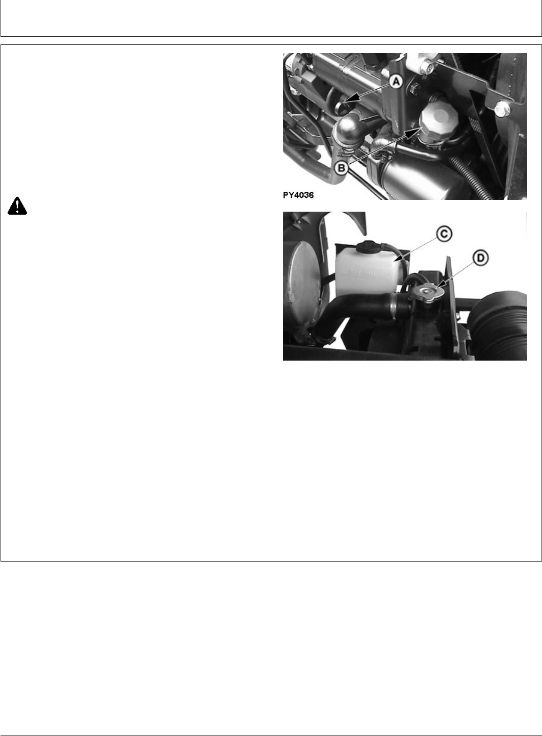
GENERIC,000003F –19–17FEB06–1/1
Service Daily Before Start-Up
PY4036 –UN–19JUN06PY5511 –UN–17FEB06
A—Engine Oil Dipstick
B—Engine Oil Filler Cap
C—Recovery Tank
D—Radiator Cap
1. Check the engine oil level. Wipe dipstick (A) off and
reinsert it fully. Remove and locate oil level.
Safe operating range is between two marks on
dipstick. Do not operate engine when oil level is below
lower mark on dipstick. Add recommended engine oil
through filler hole (B). (See Fuel, Lubricants, and
Coolant section for oil specifications.)
CAUTION: DO NOT remove radiator cap or drain
coolant until coolant is cold. Always loosen
radiator cap slowly to relieve any excess
pressure.
2. Check coolant level in recovery tank (C). If engine is
COOL and level is below “LOW” mark, add coolant to
recovery tank to bring level to “LOW” mark.
NOTE: Coolant level with a cold engine should be at the
“LOW” mark. A tractor at operating temperature
should have a coolant level at the “HOT FULL”
mark.
3. Lubricate the following items at 10 hour intervals if
operating in extremely wet or muddy conditions.
•Front axle pivot pin(s)
•Steering spindles
•Tie rod ends
Use multipurpose grease. For detailed information see
Lubrication and Maintenance section.
40-1
082206
PN=33
Operating the Engine
GENERIC,0000054 –19–11JUL06–1/1
Before Starting the Engine
TS220 –UN–23AUG88
PY5512 –UN–17FEB06PY5527 –UN–21FEB06PY4316 –UN–14DEC04
A—Gear Shift Lever
B—Range Shift Lever
C—PTO Lever
D—Rockshaft Draft Control Lever
E—Rockshaft Position Control Lever
CAUTION: Prevent asphyxiation. Engine
exhaust fumes can cause sickness or death to
you or someone else.
If you must operate engine in a building, be
positive there is adequate ventilation. Either use
an exhaust pipe extension to remove the
exhaust fumes or open doors and windows to
bring enough outside air into the area.
1. Check fuel gauge to be sure tractor has plenty of fuel.
2. Place Gear shift lever (A) in neutral (N) or Park and
Range shift lever (B) in Neutral position. Starter will not
operate if gear shift lever is not in these positions.
3. Place rockshaft control levers (D and E) in lower
position.
4. Check indicator lights. Indicators should illuminate
when key switch is turned to the “ON” position.
If any indicator does not function properly, see your
John Deere dealer.
45-1
082206
PN=34
Operating the Engine
PY80265,05I0120 –19–12SEP05–1/1
Starting the Engine
TS177 –UN–11JAN89PY4497 –UN–13JAN05
A—Hand Throttle
B—Key Switch On
1. Push hand throttle (A) forward off idle position
(approximately 1/3 of full throttle). Engine may not start
with throttle pulled completely down.
CAUTION: Avoid possible injury or death from a
machine runaway.
Do not start engine by shorting across starter
terminals. Machine will start in gear and move if
normal circuitry is bypassed.
Start engine only from operator’s seat with
transmission in NEUTRAL.
NEVER start engine while standing on ground.
IMPORTANT: DO NOT run a cold engine at full
throttle. Engine should be kept at idling
for 30 sec before the RPM is increased,
this should be strictly followed
otherwise sudden acceleration may
damage the Turbocharger.
2. Depress clutch pedal and turn key switch fully
clockwise (B) to engage starter. Release key when
engine starts. If key is released before engine starts,
wait until starter and engine stop turning before trying
again.
IMPORTANT: DO NOT operate starter more than 20
seconds at a time. If engine does not
start, wait at least two minutes for the
starter motor to cool before trying
again. If engine does not start in four
attempts, refer to “Troubleshooting”
section.
45-2
082206
PN=35
Operating the Engine
PY80265,05I0121 –19–02JUN06–1/1
Check Instruments After Starting
PY5769 –UN–02JUN06
A—Charging System Indicator
B—Oil Pressure Indicator
C—Temperature Gauge
IMPORTANT: If charging system (A) or oil pressure
(B) indicators fail to go out, or
temperature gauge (C) indicates hot,
stop engine and determine the cause.
PY80265,05I0122 –19–02JUN06–1/1
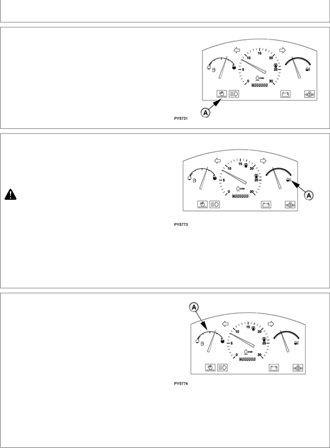
Oil Pressure Indicator
PY5770 –UN–02JUN06
A—Oil Pressure Indicator
Oil pressure indicator (A) will light if engine oil pressure is
low. Indicator should light when key is turned to engage
starter and go out when engine starts.
IMPORTANT: NEVER operate engine without
sufficient oil pressure. If indicator stays
lit for longer than five seconds under
normal operating conditions, stop
engine and check for cause.
If low oil level is not the problem, see your John Deere
dealer.
PY80265,05I0123 –19–02JUN06–1/1
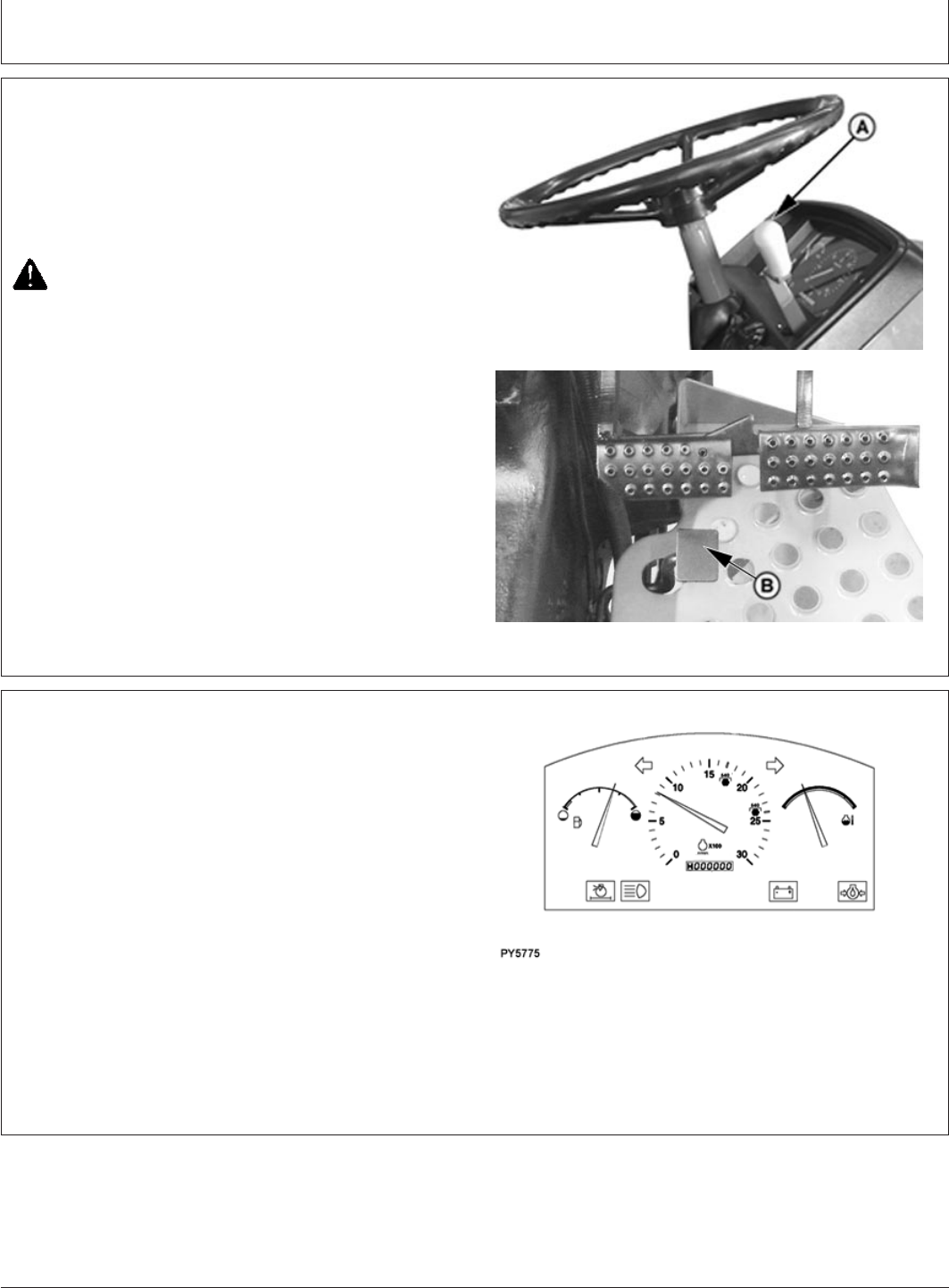
Charging System Indicator
PY5771 –UN–02JUN06
A—Charging System Indicator
Charging system indicator (A) will light when alternator
output is low. Indicator should light when key is turned to
engage starter, and go out when engine starts.
If indicator stays lit for longer than five seconds in normal
operation, stop engine and check for cause. If loose or
broken fan belt is not the cause, see your John Deere
dealer.
45-3
082206
PN=36
Operating the Engine
PY80265,05I0124 –19–02JUN06–1/1
Air Restriction Indicator
PY5731 –UN–31MAY06
A—Air Restriction Indicator
Air restriction indicator (A) will light if air cleaner becomes
plugged. Service air cleaner as soon as possible.
Indicator should light momentarily when key is turned
slowly to starter engagement position.
PY80265,05I0125 –19–02JUN06–1/1
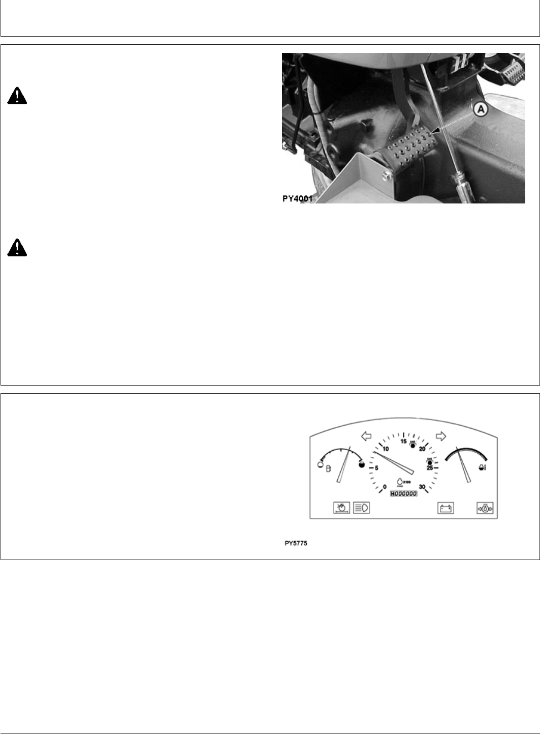
Coolant Temperature Gauge
PY5773 –UN–02JUN06
A—Coolant Temperature Gauge
The needle on the temperature gauge (A) rises as engine
warms up. If needle reaches red zone, stop engine and
determine the cause.
CAUTION: DO NOT remove radiator cap or drain
coolant until coolant is cold. Always loosen
radiator cap slowly to relieve any excess
pressure.
Check coolant level in radiator when engine cools. Also
check grille, radiator and radiator side screens for
plugging. Check fan belt tension. If problem is not
corrected, see your John Deere dealer.
PY80265,05I0126 –19–02JUN06–1/1
Watch Fuel Level
PY5774 –UN–02JUN06
A—Fuel Gauge
Stop to refuel before gauge (A) reaches empty mark.
IMPORTANT: Use diesel fuel only. See Fuel and
Lubricants section for fuel
specifications.
Should tractor run out of fuel and not start in several tries,
air must be bled from fuel system. (See Bleeding Fuel
System in Service section).
45-4
082206
PN=37
Operating the Engine
PY80265,05I0127 –19–12SEP05–1/1
Changing Engine Speeds
PY4485 –UN–16FEB06PY4937 –UN–01JUN06
A—Hand Throttle
B—Foot Throttle
To increase speed, push hand throttle (A) forward.
To temporarily increase engine speed above hand throttle
setting, depress foot throttle (B).
CAUTION: Engine should be kept at idling for
30 sec before the RPM is increased, this should
be strictly followed otherwise sudden
acceleration may damage the Turbocharger.
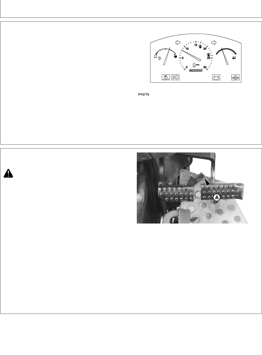
PY80265,05I0128 –19–02JUN06–1/1
Warming Up the Engine
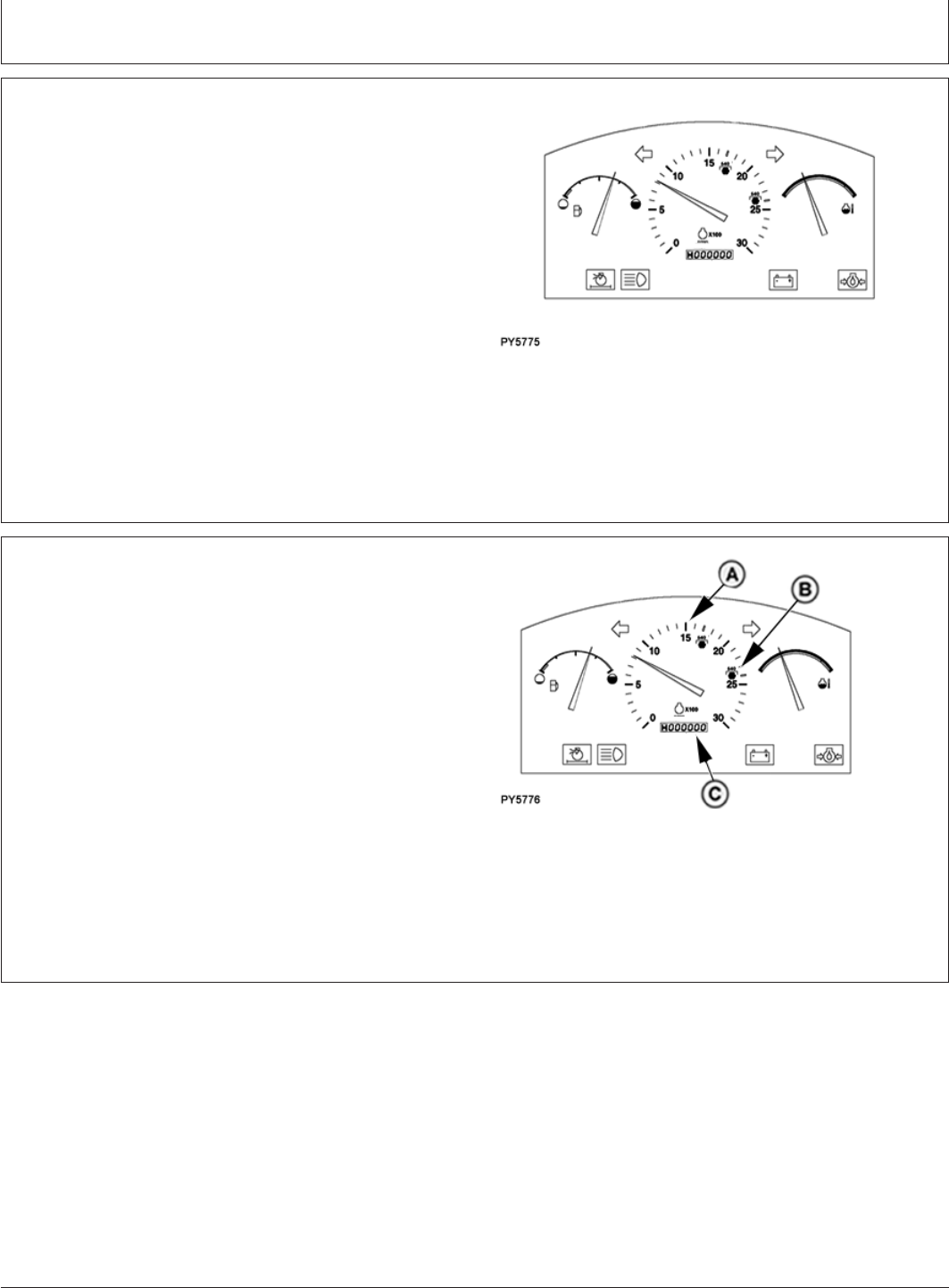
PY5775 –UN–02JUN06
Do not place tractor under full load until it is properly
warmed up.
1. Idle engine at about 1200 rpm for 1 to 2 minutes (2 to
4 minutes in cold weather) .
2. Run engine at about 1900 rpm and under light load
until engine reaches normal operation condition.
NOTE: If hydraulic functions are slow, see Warming
Hydraulic Oil in Rockshaft and 3-Point Hitch
section.
45-5
082206
PN=38
Operating the Engine
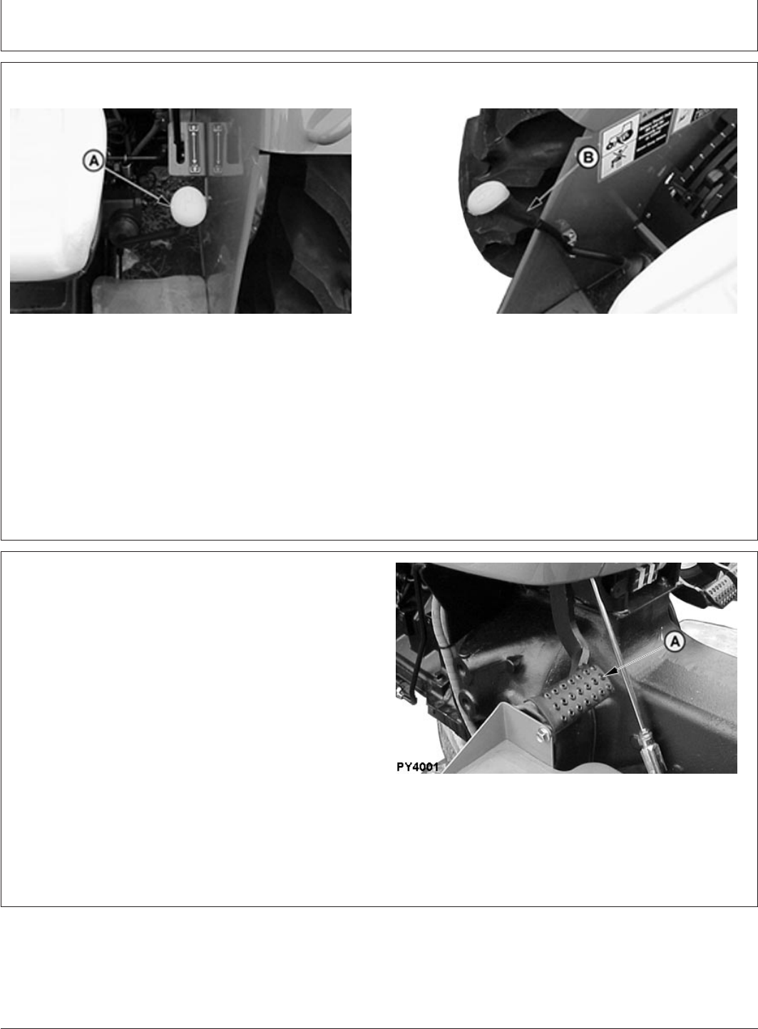
GENERIC,0000055 –19–11JUL06–1/1
Restart Stalled Engine
PY4001 –UN–06JUN06
A—Clutch Pedal
CAUTION: DO NOT run a cold engine at full
throttle. Engine should be kept at idling for 30
sec before the RPM is increased, this should be
strictly followed otherwise sudden acceleration
may damage the Turbocharger.
Should the engine stall when operating under load,
depress clutch (A) and restart it immediately to prevent
abnormal heat build up and continue with normal
operation or operate at slow idle for one or two minutes
before stopping.
CAUTION: Engine should not be shut off at high
RPM, deacceleration should be done slowly &
engine should be kept at idling for 15-30 sec
when the engine is stopped.
PY80265,05I0130 –19–02JUN06–1/1
Avoid Idling the Engine
PY5775 –UN–02JUN06
Allowing engine to idle at low RPM uses fuel inefficiently,
and can cause a build-up of carbon in the engine.
If tractor must be left with the engine running more than
three or four minutes, minimum engine speed should be
1200 RPM.
45-6
082206
PN=39
Operating the Engine
PY80265,05I0131 –19–02JUN06–1/1
Observe Engine Work and Idle Speeds
PY5775 –UN–02JUN06
Slow idle speed should be 800-875 RPM. At light or no
load, full throttle speed will increase to 2500 RPM.
Normal working speed is 1600—2400 RPM rated speed.
Within these limits engine can be put under full load.
For correct PTO speed, run engine at 2376 RPM for
standard 540 RPM operation (load requiring full engine
power).
PY80265,05I0132 –19–02JUN06–1/1
Working With Speed/Hour Meter
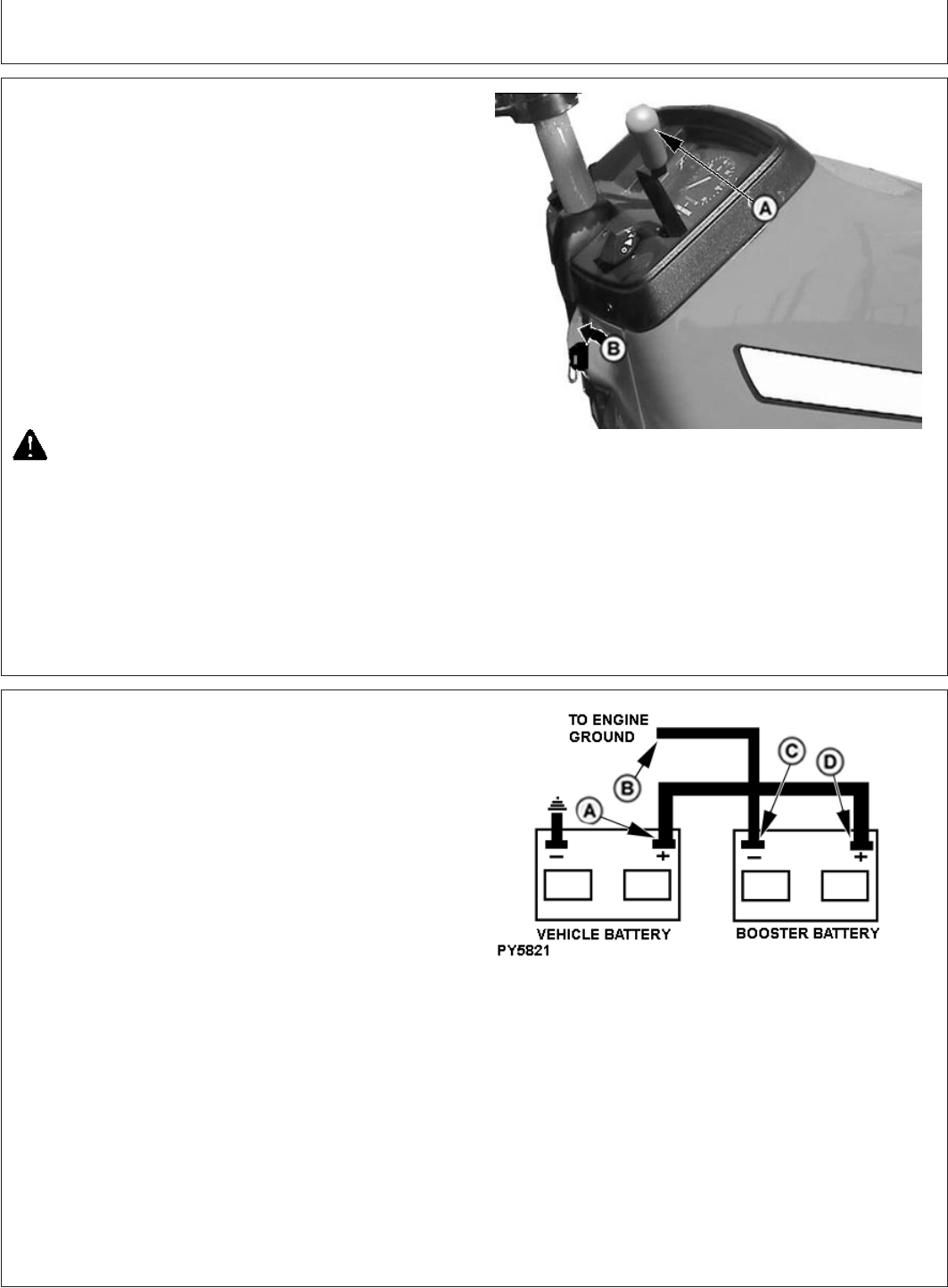
PY5776 –UN–02JUN06
A—Hourmeter
B—2376 RPM Mark (540)
C—Tachometer
Tachometer (A) shows engine RPM, read in hundreds.
For 540 RPM PTO speed, increase engine speed until
tachometer needle is aligned with 2376 RPM mark (B).
Hour meter (C) shows hours of operation in full hours and
tenths.
45-7
082206
PN=40
Operating the Engine
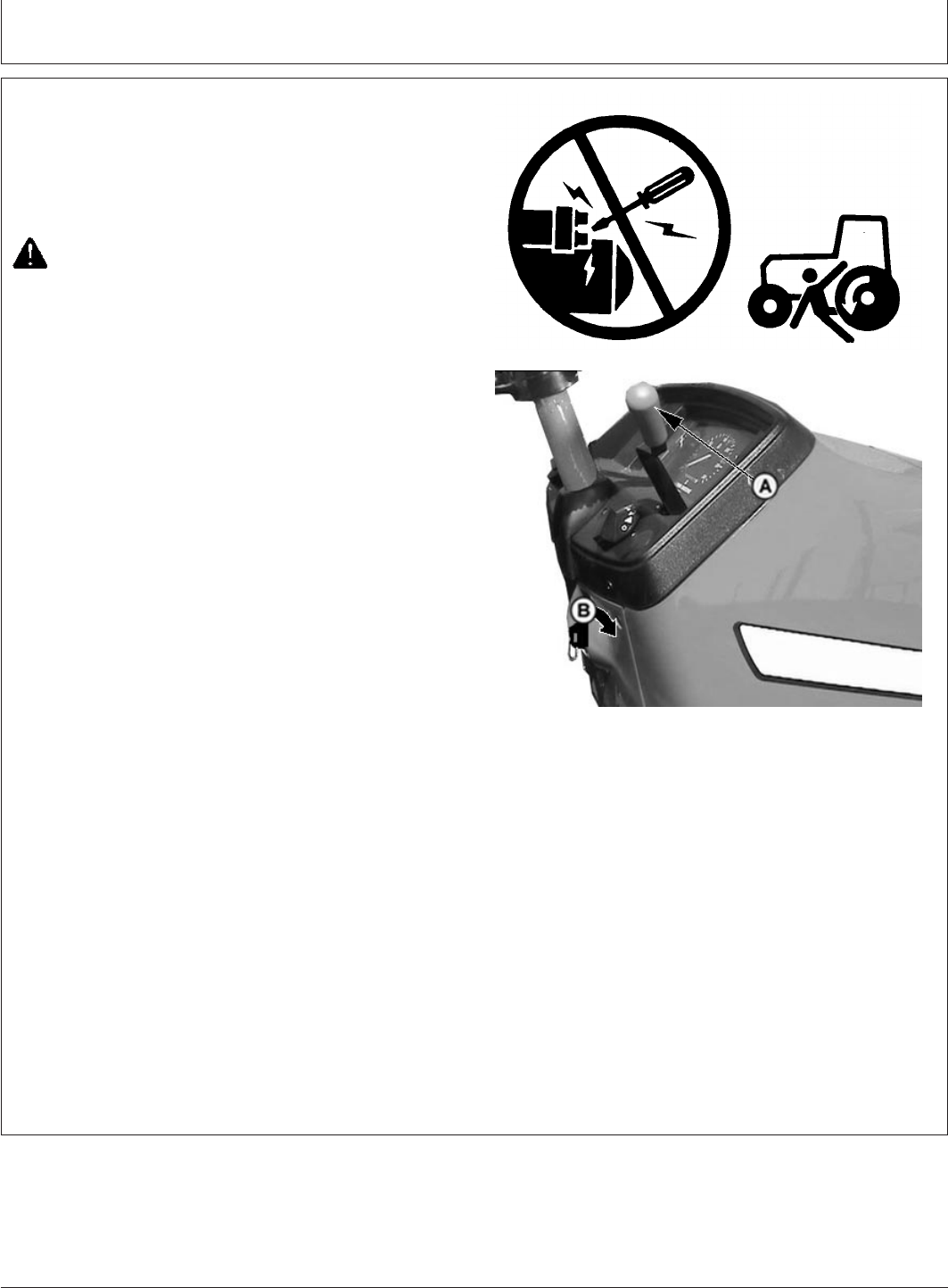
PY80265,05I0133 –19–12SEP05–1/1
Stopping the Engine
PY4501 –UN–13JAN05
A—Hand Throttle
B—Key Switch OFF
1. Pull hand throttle (A) down to slow idle position. Allow
engine to idle for one to two minutes.
2. Put gear shift lever in Park position (B).
IMPORTANT: Cooling of certain engine parts is
provided by engine oil. Stopping a hot
engine suddenly could cause damage
to these parts by overheating or lack of
lubrication.
3. Turn key switch to the OFF position.
CAUTION: Engine should not be shut off at high
RPM, deacceleration should be done slowly &
engine should be kept at idling for 15-30 sec
when the engine is stopped for a gap of 1 hr.
Remove key from key switch to prevent
operation by untrained personnel.
PY80265,05I0134 –19–12JUL06–1/1
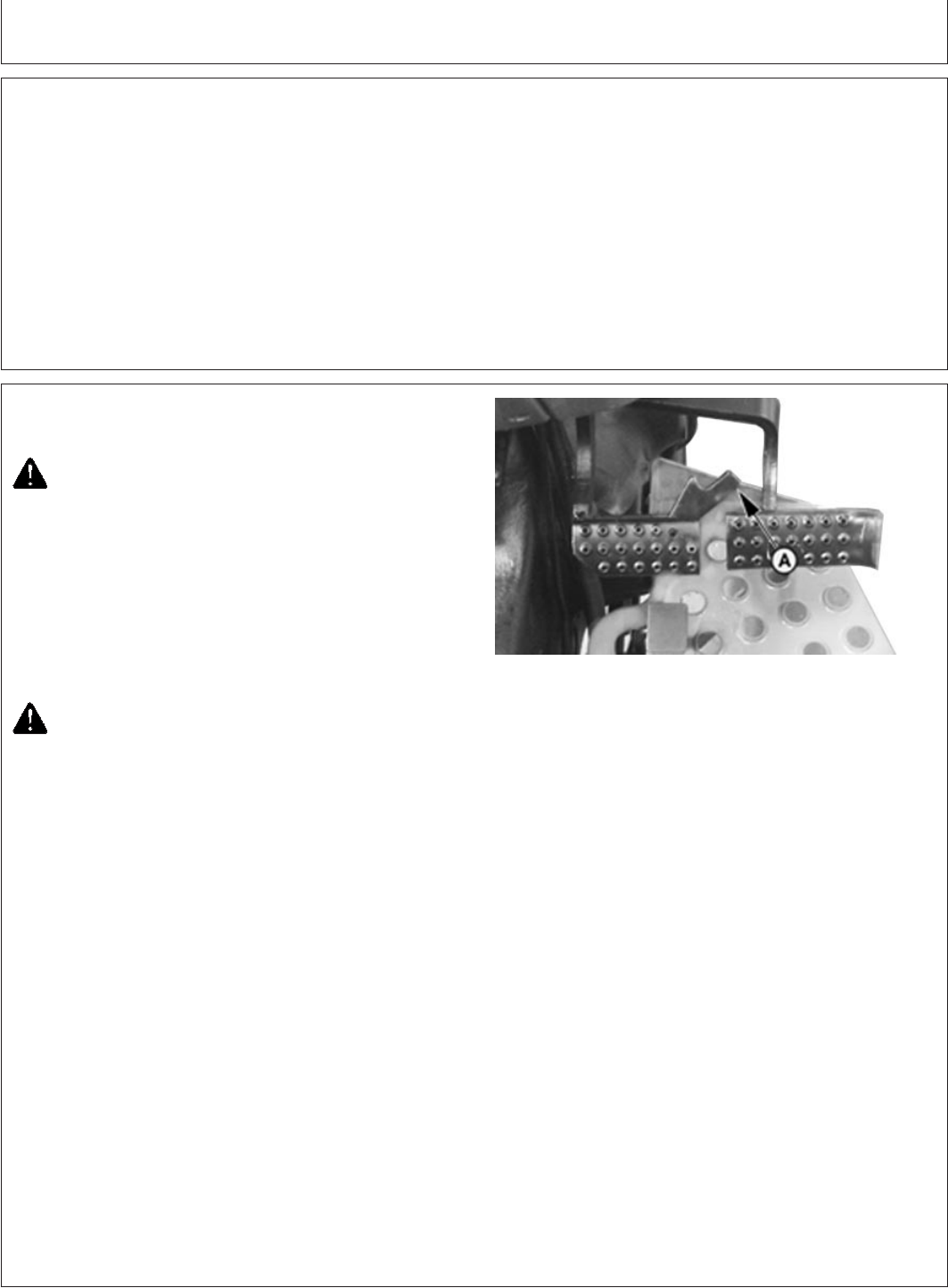
Using Booster Battery
PY5821 –UN–12JUL06
A—Tractor Battery Positive (+) Post
B—Engine Ground
C—Booster Battery Negative (—) Post
D—Booster Battery Positive (+) Post
Battery gas is explosive:
•DO NOT smoke while charging battery.
•Keep all flames and sparks away.
•DO NOT charge frozen battery.
•DO NOT connect booster battery negative (—) cable to
starting vehicle negative (—) terminal.
1. Access battery. (See procedure in Service section.)
2. Connect positive (+) booster cable to booster battery
positive (+) post (D).
3. Connect the other end of positive (+) booster cable to
tractor battery positive (+) post (A).
4. Connect negative (—) booster cable to booster battery
negative (—) post (C).
5. Connect the other end of negative (—) booster cable to
engine ground (B), away from battery and starter.
45-8
082206
PN=41
Driving the Tractor
PY80265,05I0135 –19–12SEP05–1/1
Operator Training Required
•Study the Operation section of this manual before
operating tractor.
•Operate tractor in an open, unobstructed area under
direction of an experienced operator.
•Learn use of all controls.
•Operator experience is required to learn moving,
stopping, turning and other operating characteristics
of tractor.
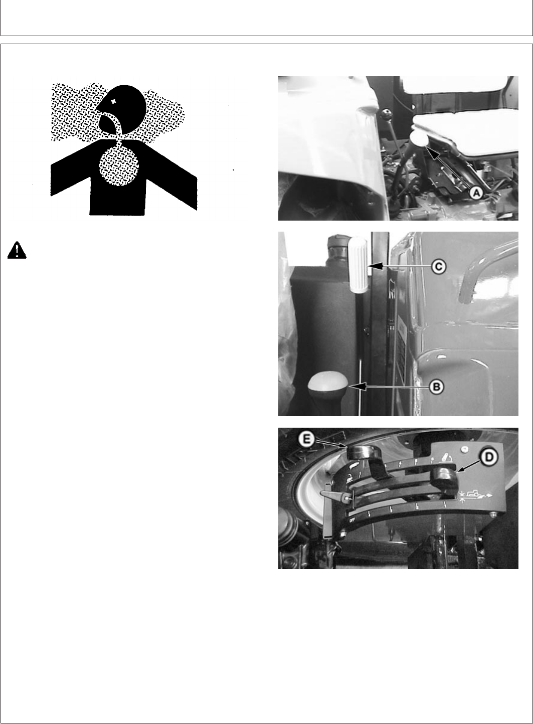
PY80265,05I0136 –19–11JUL06–1/2
Driving on Public Roads
PY4938 –UN–21FEB06
A—Brake Pedals Locking Plate
CAUTION: When transporting on a public road
or highway, use accessory lights and devices
for adequate warning to operators of other
vehicles. Check local governmental regulations.
Various safety devices are available from your
John Deere dealer. Keep safety items in good
condition. Replace missing or damaged items.
Observe the following precautions when operating the
tractor on the road:
CAUTION: Before operating tractor on a road,
lock brake pedals together. Use brake lightly
and cautiously at transport speeds.
1. Couple brake pedals together using brake locking bar
(A). Avoid hard applications of brakes. Reduce speed if
towed load weighs more than the tractor and is not
equipped with brakes.
Use additional caution when transporting towed loads
under adverse surface conditions and when turning or
braking on inclines. Be sure wheel tread is adjusted
wide to provide maximum stability.
IMPORTANT: To prevent unnecessary wear, never
ride the brakes by resting a foot on the
pedals.
50-1
082206
PN=42
Continued on next page
Driving the Tractor
PY80265,05I0136 –19–11JUL06–2/2
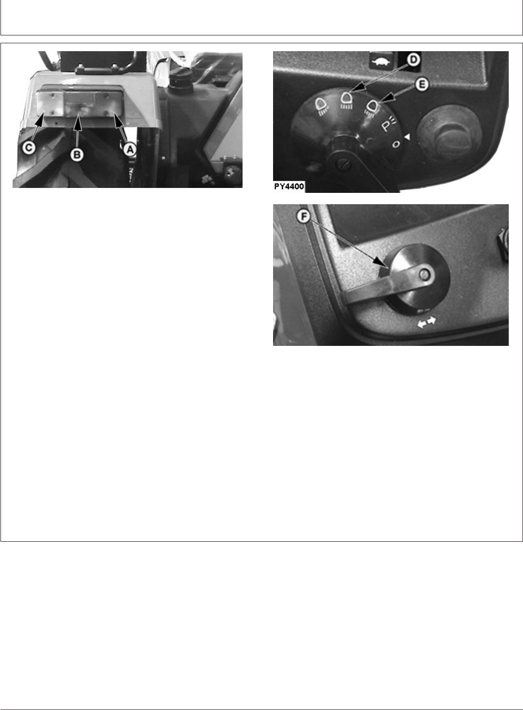
PY4883 –UN–22APR05
PY4400 –UN–15JUN06PY4469 –UN–10JAN06
A—Tail Light
B—Reflex Reflector
C—Turn Signal Light
D—Bright Headlight Switch Position
E—Dim Headlight Switch Position
F—Tail Signal Lever
2. Check local laws and regulations for lighting
requirements. Be sure turn signal lights (C) and tail
lights (A) are clean and visible.
3. Turn light switch to position (E).
Always turn light switch to dim lights position (E) when
meeting another vehicle. Never use flood lamps or any
other lights which could blind or confuse other drivers.
4. Use turn signal when turning. Be sure to return lever
(F) to center position after turning.
5. Drive slowly enough to maintain safe control at all
times. Before descending a hill, shift to a gear low
enough to control speed without using brakes. Slow
down for rough ground, and sharp turns, especially
when transporting heavy, rear mounted equipment.
50-2
082206
PN=43
Driving the Tractor
PY80265,05I0137 –19–11JUL06–1/1
Operating Transmission
PY4000 –UN–10JAN06
Left Side
PY3099 –UN–23FEB06
Right Side
A—Range Shift Lever B—Speed Shift Lever
Range shift lever (A) provides three forward speed
ranges, (A,B&C).
Using range and speed shift levers in different
combinations, nine forward speeds and three reverse
speeds can be obtained.
Range shift must be in neutral for the engine to be
started.
PY80265,05I0138 –19–12SEP05–1/1
Shifting Transmission
PY4001 –UN–06JUN06
A—Clutch Pedal
IMPORTANT: To prevent transmission damage, do
not use speed shift on-the-go. To
prevent unnecessary wear, never “ride”
the clutch by resting a foot on the
pedal.
Depress clutch pedal (A) and stop tractor before shifting
either range shift lever or gear shift lever. Release clutch
pedal gradually to take up load smoothly.
50-3
082206
PN=44
Driving the Tractor
PY80265,05I0139 –19–02JUN06–1/1
Selecting a Gear
PY5775 –UN–02JUN06
IMPORTANT: To extend drive train life and avoid
excessive soil compaction and rolling
resistance when using ballast, operate
one gear lower than normal.
The tractor may be operated in any gear with engine
speeds between 1400 RPM and 2400 rated engine RPM.
Within these limits the engine can be put under full load.
For light load operation, use a higher gear and lower
engine speed. This saves fuel and reduces wear.
Ground Speed Estimates for different tyre sizes are
located in Specifications section.
PY80265,05I0140 –19–12SEP05–1/1
Using Brakes
PY4938 –UN–21FEB06
A—Brake Pedals Locking Plate
CAUTION: Before operating tractor on a road,
lock pedals together. Use brake lightly and
cautiously at transport speeds.
Use individual brakes to assist in making sharp turns.
Disengage brake pedal locking bar (A) and depress only
one brake pedal.
To stop tractor, depress both brake pedals.
IMPORTANT: To prevent unnecessary wear, never
ride the brakes by resting a foot on the
pedals.
Reduce speed if towed load is not equipped with brakes
and weighs more than the tractor. Avoid hard braking
applications.Use additional caution when transporting
towed loads under adverse conditions, when turning or
stopping on inclines.
50-4
082206
PN=45

Driving the Tractor
PY80265,05I0141 –19–12SEP05–1/1
Using Differential Lock
PY1202 –UN–11JUN02
A—Differential Lock Pedal
CAUTION: DO NOT operate tractor at high
speed or attempt to turn with differential lock
engaged.
IMPORTANT: To prevent damage to drive train, DO
NOT engage differential lock when one
wheel is spinning and the other is
completely stopped by the respective
brake.
When one wheel starts to lose traction, engage differential
lock by depressing pedal (A) down.
Keep the pedal pressed till the traction at both the tyres
equalizes & tractor comes out of the diych. If lock does
not disengage, depress one brake pedal and then the
other.
If tyres repeatedly slip, then get to traction, then slip
again, hold pedal in the engaged position.
50-5
082206
PN=46
Driving the Tractor
PY80265,05I0142 –19–11JUL06–1/1
Stopping Tractor
PY1205 –UN–11JUN02
PY1215 –UN–11JUN02PY1469 –UN–28AUG03
A—Gear Shift Lever
B—Hand Throttle
C—Rockshaft Draft Control Lever
D—Rockshaft Position Control Lever
CAUTION: Always place the range shift lever in
neutral (N) and set brakes before dismounting.
Leaving transmission in gear with engine off
MAY NOT prevent tractor from moving.
1. Stop the tractor and place gear shift lever (A) in Park
position.
2. Apply brakes.
3. Lower all equipment to ground using rockshaft control
levers (C & D).,
4. Pull hand throttle (B) down to slow idle position. Allow
engine to idle for one to two minutes.
IMPORTANT: Cooling of certain engine parts is
provided by engine oil. Stopping a hot
engine suddenly could cause damage
to these parts by overheating or lack of
lubrication.
CAUTION: Remove the key from key switch to
prevent operation by untrained personnel.
5. Turn key switch to OFF position.
50-6
082206
PN=47
Rockshaft and 3-Point Hitch
PY80265,05I0143 –19–12SEP05–1/1
Match Tractor Power to Implement
IMPORTANT: Tractor power should be matched to the
size of certain implements. Excessive
power can damage an implement, and
too large an implement can damage the
tractor. (Refer to your implement
operators manual for minimum and
maximum power requirements before
attaching an implement.)
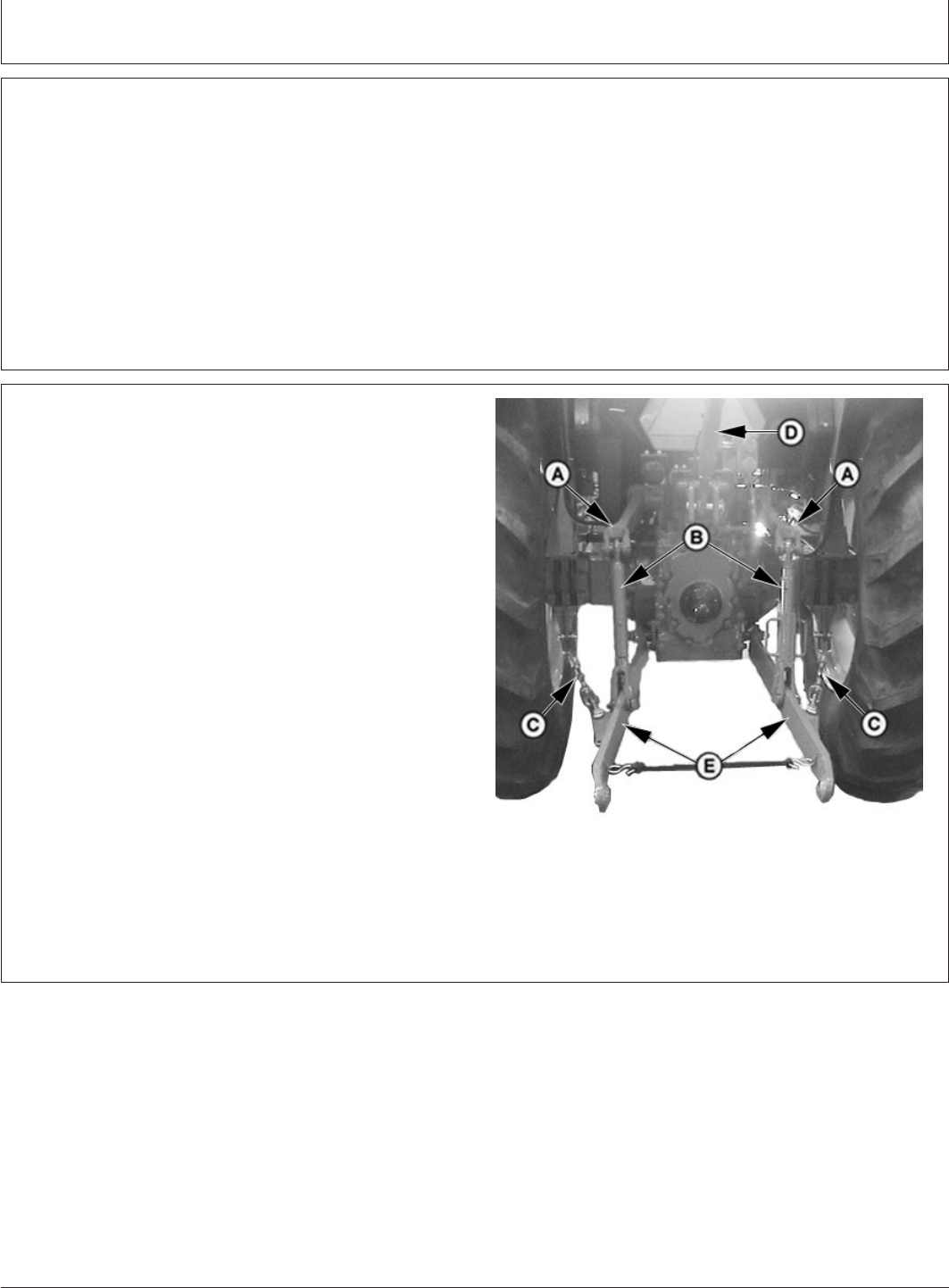
PY80265,05I0144 –19–12SEP05–1/1
3-Point Hitch Components
PY4279 –UN–17FEB06
A—Lift Arms
B—Lift Links
C—Sway Chains
D—Center Link
E—Draft Links
55-1
082206
PN=48
Rockshaft and 3-Point Hitch
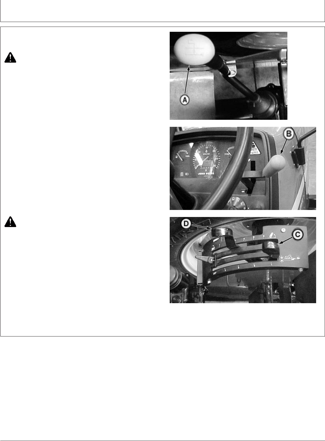
PY80265,05I0145 –19–11JUL06–1/1
Rockshaft Control Levers
PY1470 –UN–28AUG03
A—Rockshaft Position Control Lever
B—Rockshaft Draft Control Lever
The rockshaft position is controlled by two levers, the
rockshaft position control lever (A) and the rockshaft draft
control lever (B)
The rockshaft position control lever (A) raises the hitch
when pulled rearward, and lowers the hitch when moved
forward. See Using Rockshaft Position Control in this
section for more information.
The rockshaft draft control lever (B) controls hitch position
relative to draft loads. See Using Draft Control in this
section for more information.
PY80265,05I0146 –19–12SEP05–1/1
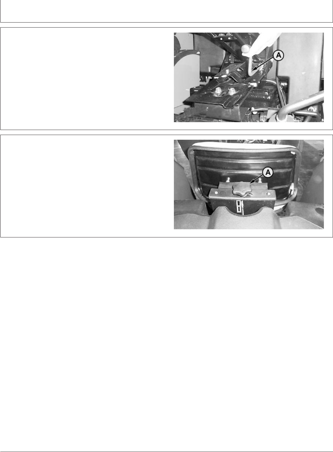
Setting Position Control Lever Stop
PY1471 –UN–28AUG03
A—Lever Stop
NOTE: Position control lever stop is used when operating
depth or height needs to be repeated.
1. Operate implement for a few minutes to determine
proper depth or height.
2. Loosen lever stop (A), and slide against position
control lever. Lock stop in position by turning in a
clockwise direction. Rockshaft will now lower to same
position each time control lever is pushed forward to
the stop.
55-2
082206
PN=49
Rockshaft and 3-Point Hitch
PY80265,05I0147 –19–12SEP05–1/1
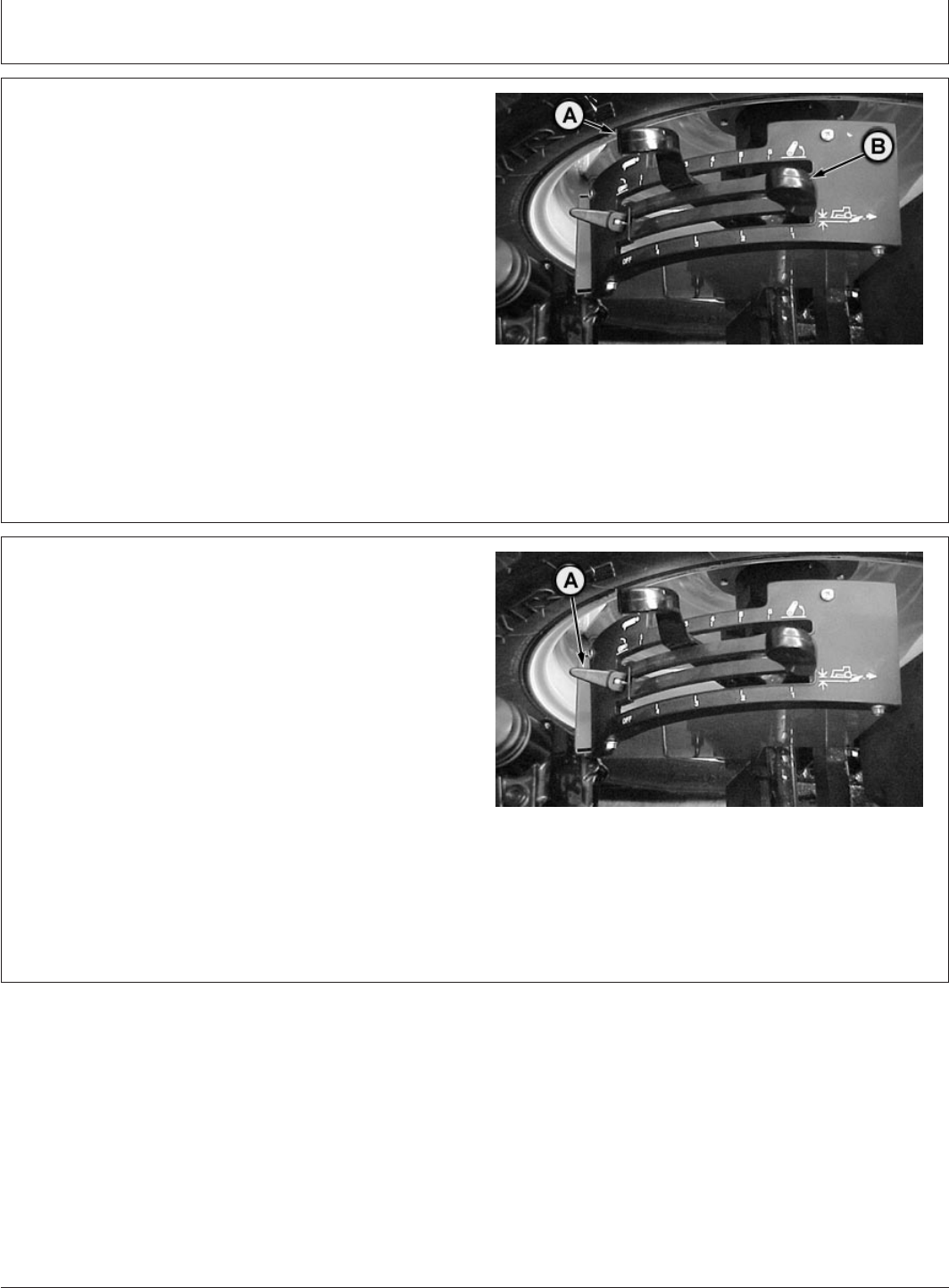
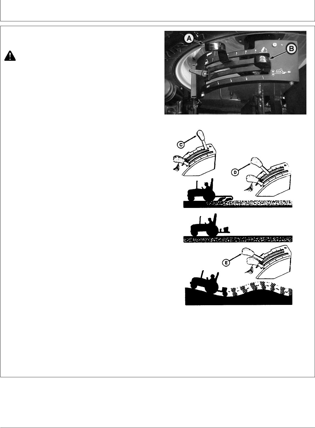
Using Rockshaft Position Control
PY1470 –UN–28AUG03M47168 –UN–31JAN92
A—Rockshaft Position Control Lever
B—Rockshaft Draft Control Lever
C—Position Control Lever in rearward position
D—Position Control Lever in desired depth position
E—Position Control Lever and Draft Control Lever in
float position
CAUTION: To prevent unexpected movement of
rockshaft, place draft control lever (B) in a full
forward position before attaching an implement.
Put draft control lever (B) forward when you DO NOT
want rockshaft to adjust automatically to draft load, such
as attaching implement to tractor.
Use position control lever (A) to control hitch movement
and depth. Position control should be used for the
following applications:
TRANSPORT of implements and end of field turn-around.
Position control lever should be moved fully rearward (C)
for transport for both load and non-load sensing usage.
CONSTANT DEPTH of implements on level terrain and
for non- ground engaging implements such as spreaders
or sprayers. Place position control lever at depth desired
(D).
FLOAT operation for implements with skids or depth
gauge wheels designed to carry full implement weight.
Push both levers all the way forward (E) so implement
can follow the ground contour.
NOTE: Lift links can be adjusted for lateral float. (See
Lateral Float in this section.)
55-3
082206
PN=50
Rockshaft and 3-Point Hitch
PY80265,05I0148 –19–12SEP05–1/1
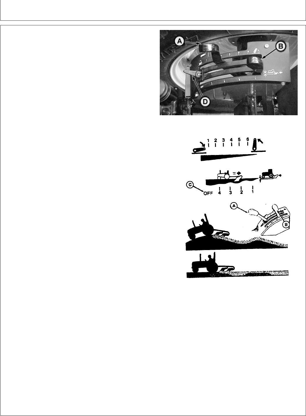
Using Draft Control
PY1472 –UN–28AUG03M47169 –19–29JAN92
A—Rockshaft Position Control Lever
B—Rockshaft Draft Control Lever
C—Draft Sensing Off Position
D—Position Control Lever Stop
The rockshaft is equipped with variable draft control
system.
Use draft load sensing when:
•Operating with a fully mounted implement in hill and
swale terrain. The implement will raise and lower to
follow the ground contours while maintaining a nearly
constant depth.
•Operating in varying soil conditions. The implement is
raised slightly to get through tough spots so you do not
have to shift to a lower gear.
Draft control lever (B) controls amount of load required
before hitch responds. With lever placed fully forward to
the position marked “off” (C), there is no draft sensing.
Placing the lever toward the rear position reduces the
amount of draft load required to override the position
setting set by the position control lever (A) and raise the
rockshaft.
Draft sensitivity ranges can be changed by repositioning
the center link. (See Positioning Center Link in this section
for additional information.)
For draft load sensing operation:
•Initially place position control lever (A) in its fully
rearward position and the draft control lever (B) in the
fully forward (least draft) position.
•With tractor moving, push position control lever (A)
forward to set implement operating depth. Set position
control lever stop (D) so control lever can be brought
back to the same position. The operating depth set-up
will prevent the rockshaft from lowering all the way
when the tractor begins to slip. Then pull draft sensing
lever (B) rearward until desired draft sensing sensitivity
is obtained.
•The position control lever (A) can also be raised slightly
to override the draft control setting to help get through
slippery spots without getting stuck.
•The position control lever (A) can be moved fully
rearward to raise the hitch at the end of the field.
55-4
082206
PN=51
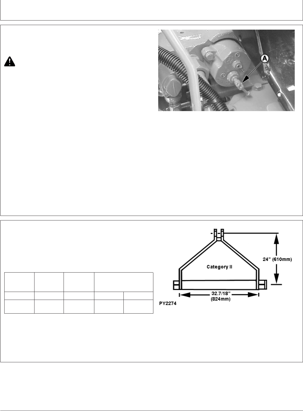
Rockshaft and 3-Point Hitch
PY80265,05I0149 –19–12SEP05–1/1
Adjusting Rockshaft Rate-of-Drop/ Implement
lock
PY4543 –UN–23JAN05
A—Rockshaft Rate-Of-Drop Knob cum Implement
Lock
CAUTION: Excessive rate-of-drop may cause
damage or injury. Fully lowering implement
should require at least two seconds.
Rockshaft drops faster when a heavy implement is
attached. Adjust rate-of-drop knob so that it is slow
enough to be safe and prevent implement damage.
Turn rockshaft rate-of-drop knob (A), located under the
seat, clockwise to slow rockshaft drop.
Turn knob counterclockwise to increase rate-of-drop.
Rate-of-drop knob is also called implement lock. When
knob is fully screw in, implement will not lower down even
if position control lever is fully down. Use implement lock
while transporting implement.
PY80265,05I0150 –19–12SEP05–1/1
Preparing Implement
PY2274 –UN–07JUN06
Category II implements should have the top hole of the
implement mast located 610 mm (24 in.) above the lower
pins. Drill another hole in top mast or extend top mast if
necessary.
Category Mast Width Pin Size
Height Between
Lower Pins
Lower Upper
II 610 mm 824 mm 28.7 mm 25.5 mm
(24 in.) (32-7/16 in.) (1-1/8 in.) (1 in.)
55-5
082206
PN=52
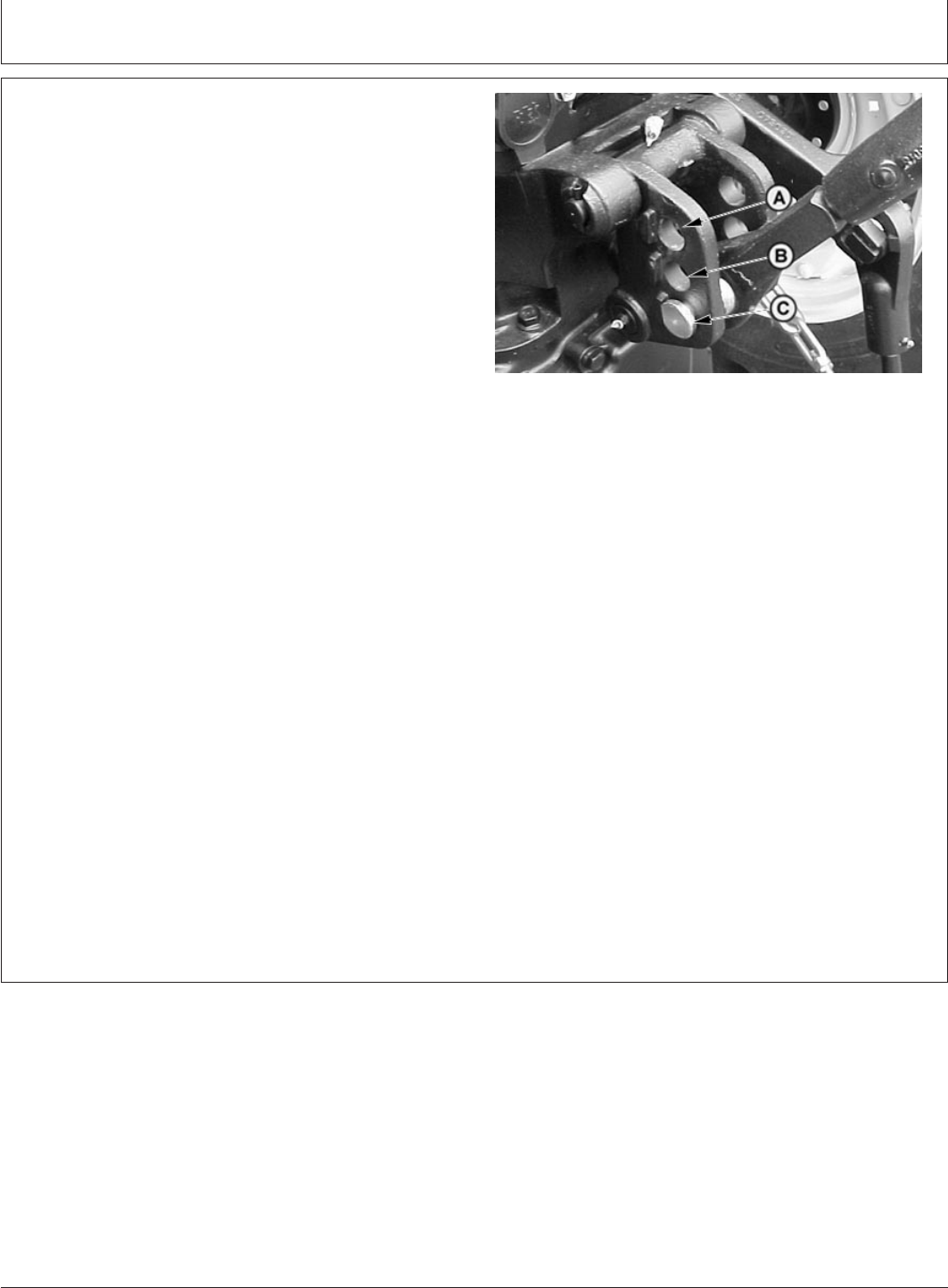
Rockshaft and 3-Point Hitch
PY80265,05I0151 –19–12SEP05–1/1
Positioning Center Link
PY4005 –UN–14JUL04
A—Upper Hole
B—Middle Hole
C—Lower Hole
The draft sensing rockshaft center link attaching bracket
has holes which allow three different positions for
attaching the center link. The position effects the draft
sensing sensitivity.
Standard position is (C).
Move the center link attachment to holes (B) if:
•Excessive hitch activity or hunting occurs in draft control
operation.
•The rear of the implement raises too much when lifted.
The implement weight which can be lifted is reduced
slightly with the center link attachment in the lower
holes.
•The draft control lever range is too small.
Move the center link attachment to holes (C) if:
•The hitch seems unresponsive in draft control operation
and allows the engine speed to drop too far before
raising the rockshaft.
•The rear of the implement droops and drags the ground
as the implement is lifted.
Upper hole (A) eliminates nearly all draft sensing.
NOTE: Implement with Category II mast height 610 mm
(24 in.) will use the upper two holes.
55-6
082206
PN=53
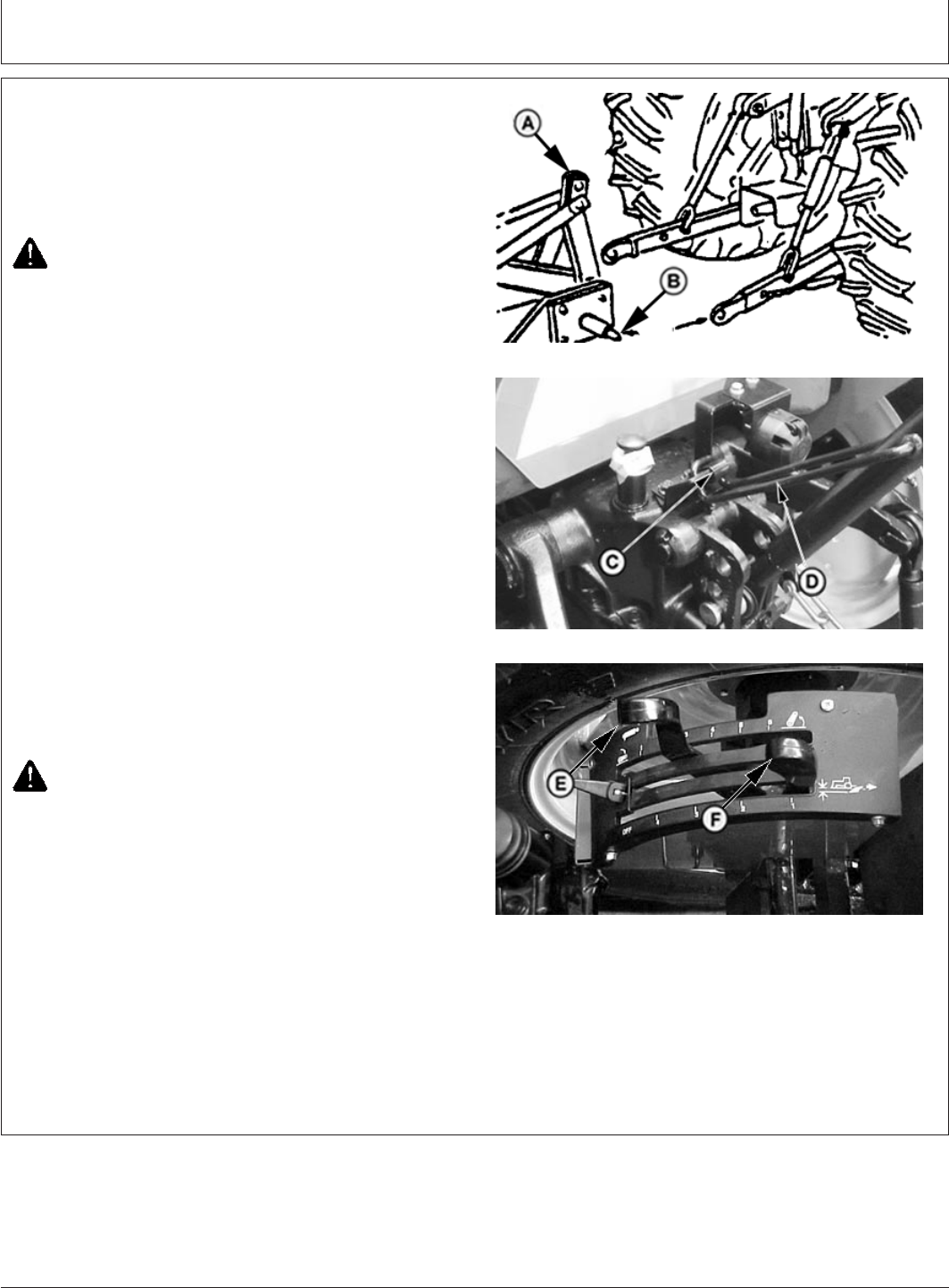
Rockshaft and 3-Point Hitch
GENERIC,000004D –19–11JUL06–1/1
Attaching Implements to 3-Point Hitch
PY5374 –UN–09DEC05
Align Hitch Point
PY5375 –UN–09DEC05
Central Link Locking Clip
PY5530 –UN–22FEB06
Rockshaft Control Lever
A—Implement
B—Implement Hitch Pins
C—Center Link Locking Clip
D—Tab
E—Rockshaft Position Control Lever
F—Rockshaft Draft Control Lever
1. Be sure drawbar will not interfere. If necessary, move
drawbar ahead, or remove it. Check for any other
potential interference.
CAUTION: Prevent unexpected movement of
rockshaft by placing draft sensing lever in the
forward or OFF position before attaching
implement to hitch.
2. Back tractor up to implement (A) so hitch points align.
Place transmission in neutral (N), stop the engine and
engage brakes BEFORE leaving the tractor seat.
3. Slip draft links over implement hitch pins (B) and retain
with quick-lock pins.
NOTE: Locking pins can be stored on draft links (through
holes in sway chain ears) when not in use.
4. To remove center-link from transport hook, lift center
link locking clip (C) and rotate tab (D) to rear of center
link clip.
5. Attach center link to implement top mast.
6. Adjust center link and lift links as necessary. (See
Leveling the Hitch in this section.)
CAUTION: To avoid bodily injury or machine
damage whenever an implement, implement
quick coupler, or other attachment is connected
to the tractor 3-Point Hitch, check full range of
operation for interference, binding or PTO
separation.
7. Using Rockshaft Position Control Lever (E), lower and
raise implement slowly and check for any point of
interference.
55-7
082206
PN=54

Rockshaft and 3-Point Hitch
PY80265,05I0153 –19–12SEP05–1/1
Adjusting Hitch Side Sway
PY4892 –UN–14APR05
A—Threaded Link
NOTE: Check implement operator’s manual for instruction
on whether to allow side sway.
IMPORTANT: DO NOT shorten chains so short that
they do not allow hitch to be raised
completely. If chain prevents hitch from
raising, hydraulic relief valve will open,
causing excessive oil heating, pump
damage or equipment damage.
NOTE: Use spring or rubber strap to keep draft links out
of rear tyres when draft links are not attached to
implement.
Implement side sway should be adjusted when the
rockshaft is raised for transport by loosening the jam nut
on the threaded link (A) and turning the center rod to
increase or decrease the length of chain. Tighten jam nut
again when adjusted.
55-8
082206
PN=55
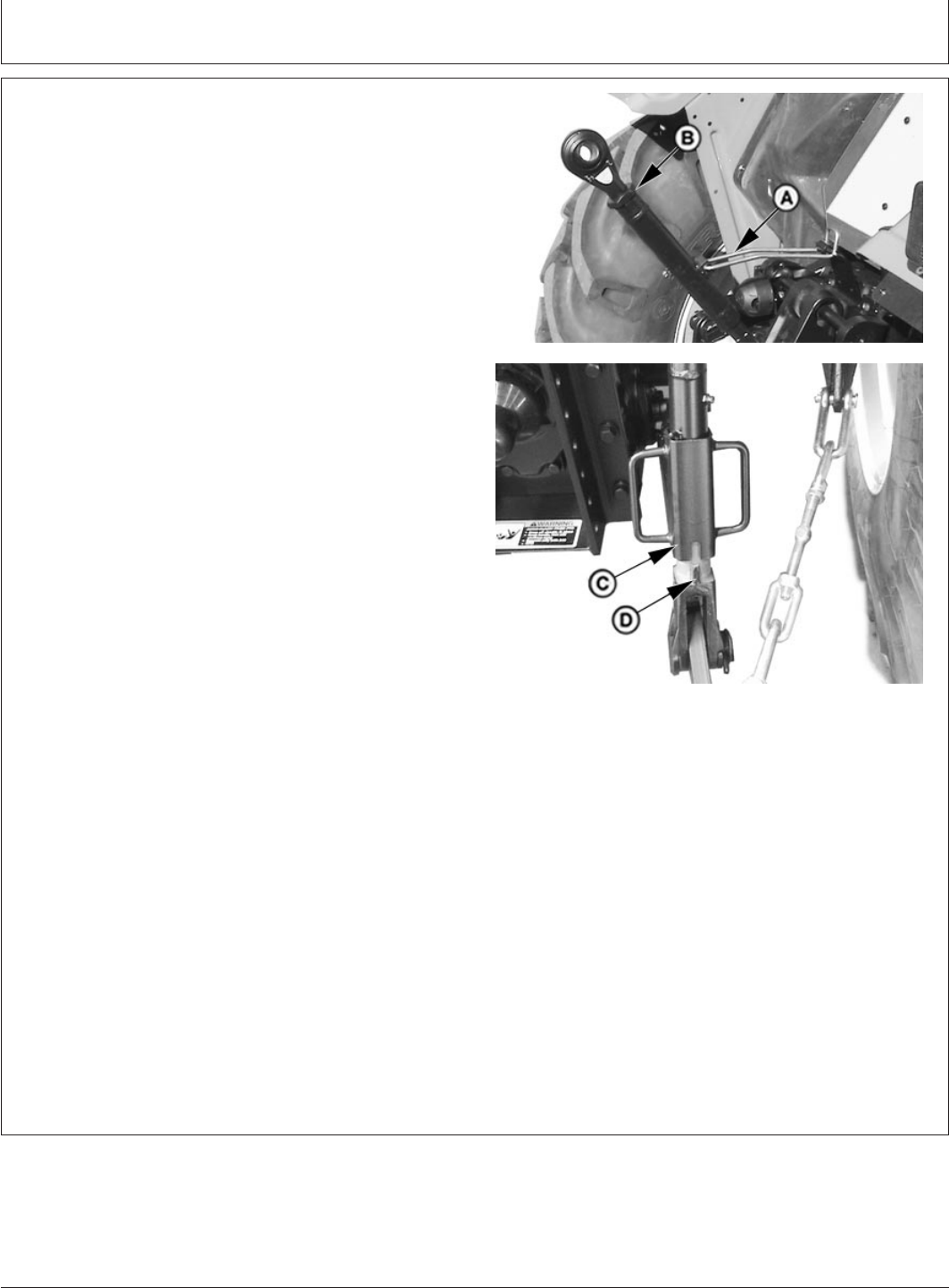
Rockshaft and 3-Point Hitch
GENERIC,0000064 –19–08MAR06–1/1
Leveling the Hitch
PY5285 –UN–24NOV05PY5459 –UN–09JAN06
A—Locking Clip
B—Center Link Body
C—Locking Handle
D—Slot
1. Lower implement to take weight off hitch.
IMPORTANT: DO NOT attempt to overextend center
link beyond limits of locking clip or lift
links past the stops. Link body threads
could be damaged.
NOTE: Maximum adjustment range of the center link can
only be obtained if the ends are positioned equally
within the body when attached to an implement.
2. Adjust center link to level implement front-to-rear.
Unlatch locking clip (A). Rotate center link body (B)
clockwise to lengthen center link or counterclockwise to
shorten it. Be sure to latch the locking clip.
3. Adjust right-hand link to level implement side-to-side.
Lift locking handle (C and turn 1/4 turn to engage slot
(D) onto roll-pin in the center portion of the lift link.
Turn crank handle clockwise to raise draft link.
Turn crank handle counterclockwise to lower draft link.
After adjustment, lift handle (C) and turn to engage slot
(D) onto the lower body to prevent change of
adjustment during operation.
4. The left-hand lift link is also adjustable in length to
accommodate different tyre sizes.
To change the left-hand lift link length, remove the
upper lift link pin and rotate the upper end assembly
clockwise to shorten or counterclockwise to lengthen,
and then reinstall the upper pin and locking pin.
Adjust left and right lift links to accommodate various
tyre sizes. Set the lift links to have fully-lowered draft
link balls approximately seven inches off the ground for
greatest range of usable hitch motion.
55-9
082206
PN=56
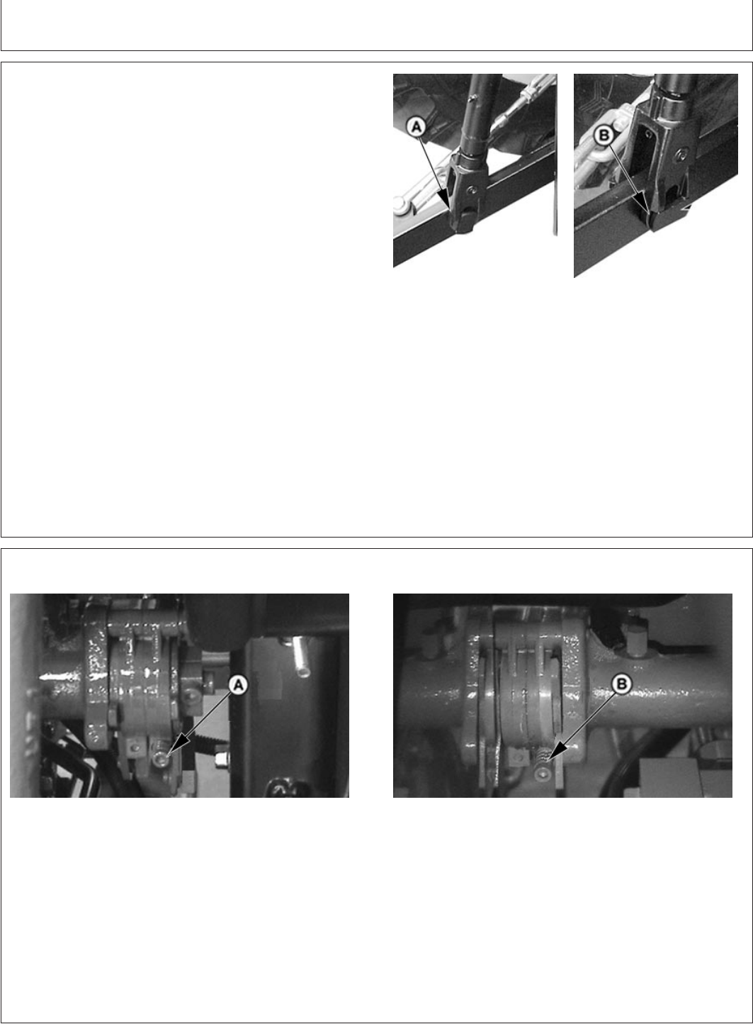
Rockshaft and 3-Point Hitch
GENERIC,0000042 –19–22FEB06–1/1
Adjusting Lateral Float
PY5381 –UN–10DEC05
PY5380 –UN–10DEC05
A—Pin In Vertical Position
B—Pin In Horizontal Position
To allow the draft link to raise slightly as implement
follows ground contour, place head of float pin and the
rectangular washer on the inside end of the pin in a
vertical position (A).
To hold implement rigid, place head of float pin and the
rectangular washer in the horizontal position (B).
Use lift link pins in the float position for hitch-mounted
implements such as a cultivator or mower, which have
ground gauging skids or wheels which may cause the
implement to twist relative to the tractor.
Use the rigid position for implements such as plows and
ground engaging implements that should not twist relative
to the tractor.
PY80265,05I0156 –19–12SEP05–1/1
Adjusting Rockshaft Control Lever Friction
PY4406 –UN–10DEC05
PY4385 –UN–10DEC05
A—Adjustment Set Screws
If the rockshaft position control lever or rockshaft draft
control lever do not stay in set position, increase lever friction by tightening the set screws (A) for the
appropriate lever until the proper friction is obtained.
55-10
082206
PN=57
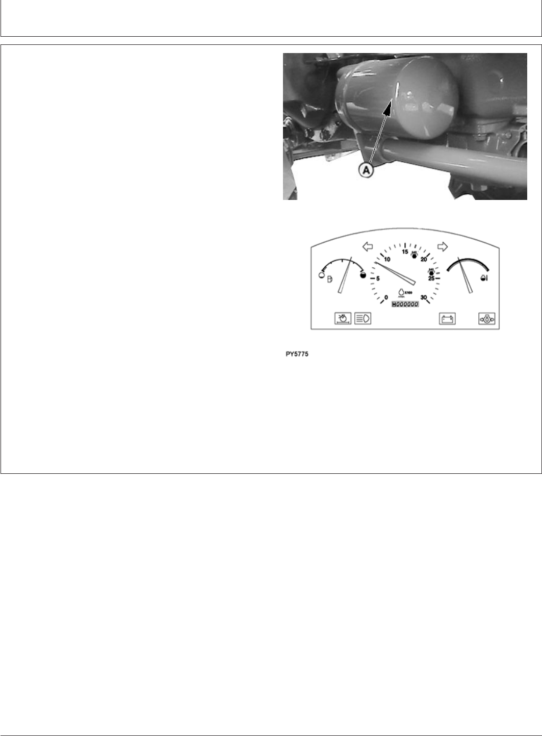
Rockshaft and 3-Point Hitch
PY80265,05I0157 –19–02JUN06–1/1
Warming Hydraulic System Oil
PY4407 –UN–22FEB06PY5775 –UN–02JUN06
A—Hydraulic Oil Filter
Hydraulic system may be slow to function when tractor is
started in cold weather. This is because cold oil will not
flow as easily through the hydraulic system filter (A).
Steering may be slow until system warms up.
Hydraulic system will function normally when oil warms
up.
IMPORTANT: To prevent damaging hydraulic pump or
relief valve, DO NOT exceed two to
three minutes warm-up time with
steering wheel held in full left or full
right turn position.
1. Depress clutch pedal, start engine and idle at about
1000 RPM.
2. Turn and hold steering wheel in full left or right turn.
55-11
082206
PN=58
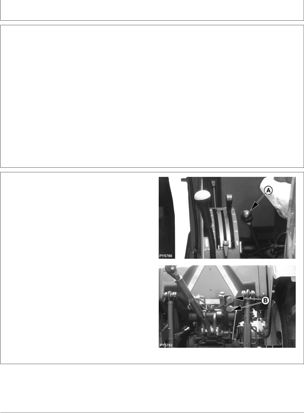
Remote Hydraulic Cylinders
PY80265,05I0158 –19–12SEP05–1/1
Use Correct Hose Tips
If your tractor is equipped with a selective control valve
(SCV), the couplers receptacles accept a standard hose
tip as recommended by ISO
1
and SAE
2
. Adapters are
available to allow connecting the older John Deere hose
tips to the ISO couplers on your tractor.
1
International Standards Organization
2
Society of Automotive Engineers
PY80265,05I0159 –19–08JUN06–1/1
Control Lever and Coupler Identification—If
Equipped
PY5789 –UN–08JUN06PY5792 –UN–08JUN06
A— SCV Lever
B—SCV Receptacles
Movement of SCV lever (A) fore and aft operates coupler
receptacles (B).
Coupler has a detented float position when lever (A) is
moved in the fully forward direction.
60-1
082206
PN=59
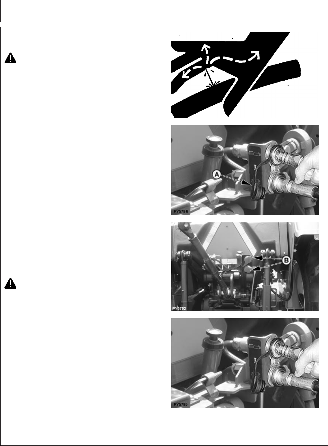
Remote Hydraulic Cylinders
GENERIC,000004F –19–08JUN06–1/1
Connecting Hoses
X9811 –UN–23AUG88
PY5796 –UN–08JUN06PY5792 –UN–08JUN06PY5795 –UN–08JUN06
A—Dust Plug
B— Receptacle
CAUTION: Escaping fluid under pressure can
penetrate the skin causing serious injury. Avoid
the hazard by relieving pressure before
disconnecting hydraulic or other lines. Tighten
all connections before applying pressure.
Search for leaks with a piece of cardboard.
Protect hands and body from high pressure
fluids.
If an accident occurs, see a doctor immediately.
Any fluid injected into the skin must be
surgically removed within a few hours or
gangrene may result. Doctors unfamiliar with
this type of injury should reference a
knowledgeable medical source. Such
information is available from Deere & Company
Medical Department in Moline, Illinois, U.S.A.
1. Remove dust caps (if equipped) from hose end.
2. Pull dust plug (A) from couplers.
3. Make sure hose end and coupler receptacles are
clean.
4. Check hoses to see which is used for extending
cylinder. This hose must be connected to a coupler
receptacle (B) in order for cylinder to extend when
SCV levers are moved rearward or inward.
CAUTION: Hydraulic hoses can fail due to
physical damage, kinks, age and exposure.
Check hoses regularly. Replace damaged
hoses. See your John Deere dealer.
5. To connect each hose, push hose tip firmly into
coupler receptacle. Pull lightly on hose to make sure
positive connection was made.
60-2
082206
PN=60
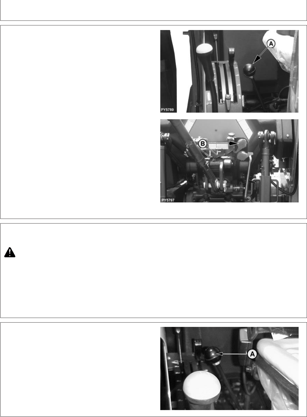
Remote Hydraulic Cylinders
GENERIC,0000050 –19–20FEB06–1/1
Connecting Single-Acting Cylinder
PY5789 –UN–08JUN06PY5797 –UN–08JUN06
A—SCV Outlet Lever
B—SCV Outlet
In order for lever (A) to work properly, a single-acting
cylinder should be connected only to SCV outlet in the
extend position (top coupler) (B).
IMPORTANT: Volume of oil required to extend
cylinder must not lower
transmission-hydraulic oil level below
lower sight glass. Check oil level with
cylinder fully extended. (See Check
Transmission-Hydraulic Oil Level in
Service—50 Hours chapter.)
Push SCV No. 1 control lever full forward to use “float”
position to lower single-acting cylinder.
“Float” position allows a cylinder to extend and retract
freely and uses no engine power.
PY80265,05I0162 –19–12SEP05–1/1
Correcting Reversed Cylinder Response
CAUTION: If cylinder response is reversed,
extending when it should retract, reverse
cylinder hose connections at coupler.
GENERIC,0000051 –19–20FEB06–1/1
Neutral Lever Position
PY2245 –UN–20FEB06
A—SCV Lever
Spring pressure returns lever (A) to a centered position
(except when lever is fully forward in the “Float” position).
When the control levers are in the centered position, the
remote cylinder is hydraulically locked in position.
60-3
082206
PN=61
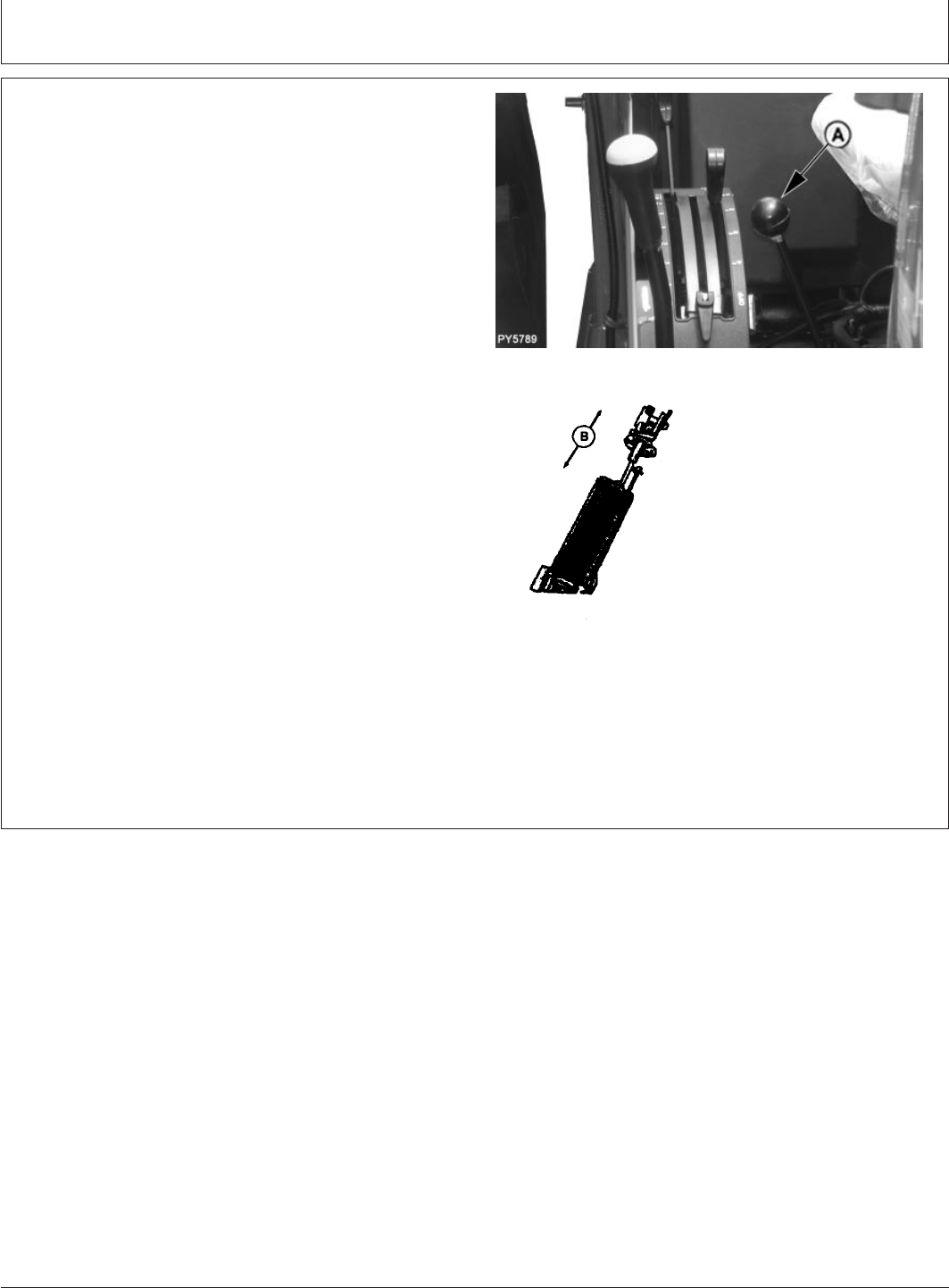
Remote Hydraulic Cylinders
GENERIC,0000052 –19–20FEB06–1/1
Extending/Retracting Cylinder
PY5789 –UN–08JUN06
M47174 –UN–31JAN92
A—Control Lever
B—Extend and Retract Cylinder
Extending Cylinder
Pull lever (A) to the rear of neutral and hold it against
spring pressure. This extends cylinder (B) (up arrow)
connected to couplers and in most cases raises
implement. Lever returns to neutral when released.
Retracting Cylinder
Push lever (A) forward and hold it against spring pressure.
This retracts cylinder (B) connected to SCV couplers and
in most cases lowers implement. Lever returns to neutral
when released.
Float Position
Push lever full forward into detent to operate Float feature.
Float operation allows cylinder to extend and retract
freely, such as when an implement follows ground
contour.
IMPORTANT: When “Float” is not needed, manually
move lever back to neutral position to
prevent accidental use of “Float”.
60-4
082206
PN=62
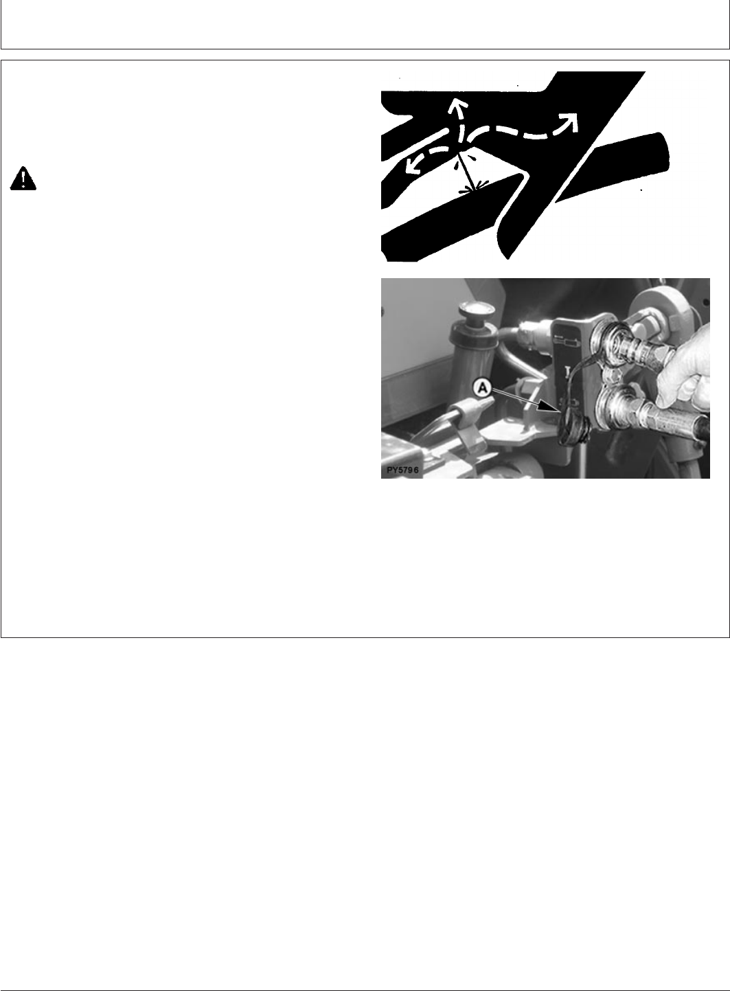
Remote Hydraulic Cylinders
PY80265,05I0156 –19–08JUN06–1/1
Disconnecting Hoses
X9811 –UN–23AUG88
PY5796 –UN–08JUN06
A—Dust Plug
1. If possible, retract remote cylinder as much as possible
to protect cylinder rod from damage.
CAUTION: Escaping fluid under pressure can
penetrate the skin causing serious injury. Avoid
the hazard by relieving pressure before
disconnecting hydraulic or other lines. Tighten
all connections before applying pressure.
Search for leaks with a piece of cardboard.
Protect hands and body from high pressure
fluids.
If an accident occurs, see a doctor immediately.
Any fluid injected into the skin must be
surgically removed within a few hours or
gangrene may result. Doctors unfamiliar with
this type of injury should reference a
knowledgeable medical source. Such
information is available from Deere & Company
Medical Department in Moline, Illinois, U.S.A.
2. With as much hydraulic pressure relieved as possible
from hoses, pull hoses from couplers.
3. Make sure dust plugs (A) for receptacles and dust
caps for hoses are clean, then install dust plugs.
60-5
082206
PN=63
Drawbar and PTO
PY80265,05I0157 –19–12SEP05–1/1
Observe Drawbar / Wagon Hitch Load
Limitations
IMPORTANT: Certain heavy equipment, such as a
loaded single-axle trailer, can place
excessive strain on drawbar. Strain is
greatly increased by speed and rough
ground.
Static vertical load on drawbar/wagon
hitch should not exceed 556 kg (1225
lb).
Drive slowly with heavy loads.
PY80265,05I0158 –19–12SEP05–1/1
Stay Clear of Rotating Drivelines
TS1644 –UN–22AUG95
Entanglement in rotating driveline can cause serious injury
or death.
Keep tractor master shield and driveline shields in place
at all times. Make sure rotating shields turn freely.
Wear close fitting clothing. Stop the engine and be sure
PTO driveline is stopped before making adjustments,
connections, or cleaning out PTO driven equipment.
65-1
082206
PN=64

Drawbar and PTO
PY80265,05I0159 –19–12SEP05–1/1
Attaching PTO-Driven Implement
PY1094 –UN–10APR05
CAUTION: Stop engine before attaching
implement or working in area of implement
hitch.
1. Attach implement to tractor before connecting PTO
drive line. Raise hitch to upward position if it is not to
be used.
2. Range shift lever in neutral (N), turn key to OFF
position, pull fuel shut-off knob to stop engine and set
brakes.
3. Attach implement to 3-Point Hitch, be sure drawbar will
not interfere. Remove it if necessary.
4. Rotate PTO shield upward for clearance. With engine
off, turn shaft slightly by hand if necessary to line up
splines. Connect drive line to PTO shaft. Pull out on
shaft to be sure drive line is locked to PTO shaft. Place
PTO shield in downward position.
5. Be sure all shields are in place and in good condition.
Never operate PTO unless master shield is properly
installed. WITH ENGINE STOPPED, check integral
shields on drive line by making sure they rotate freely
on shaft. Lubricate or repair as necessary.
6. Check carefully for any interference, make sure hitch is
raised to the upper position if it is not used.
65-2
082206
PN=65
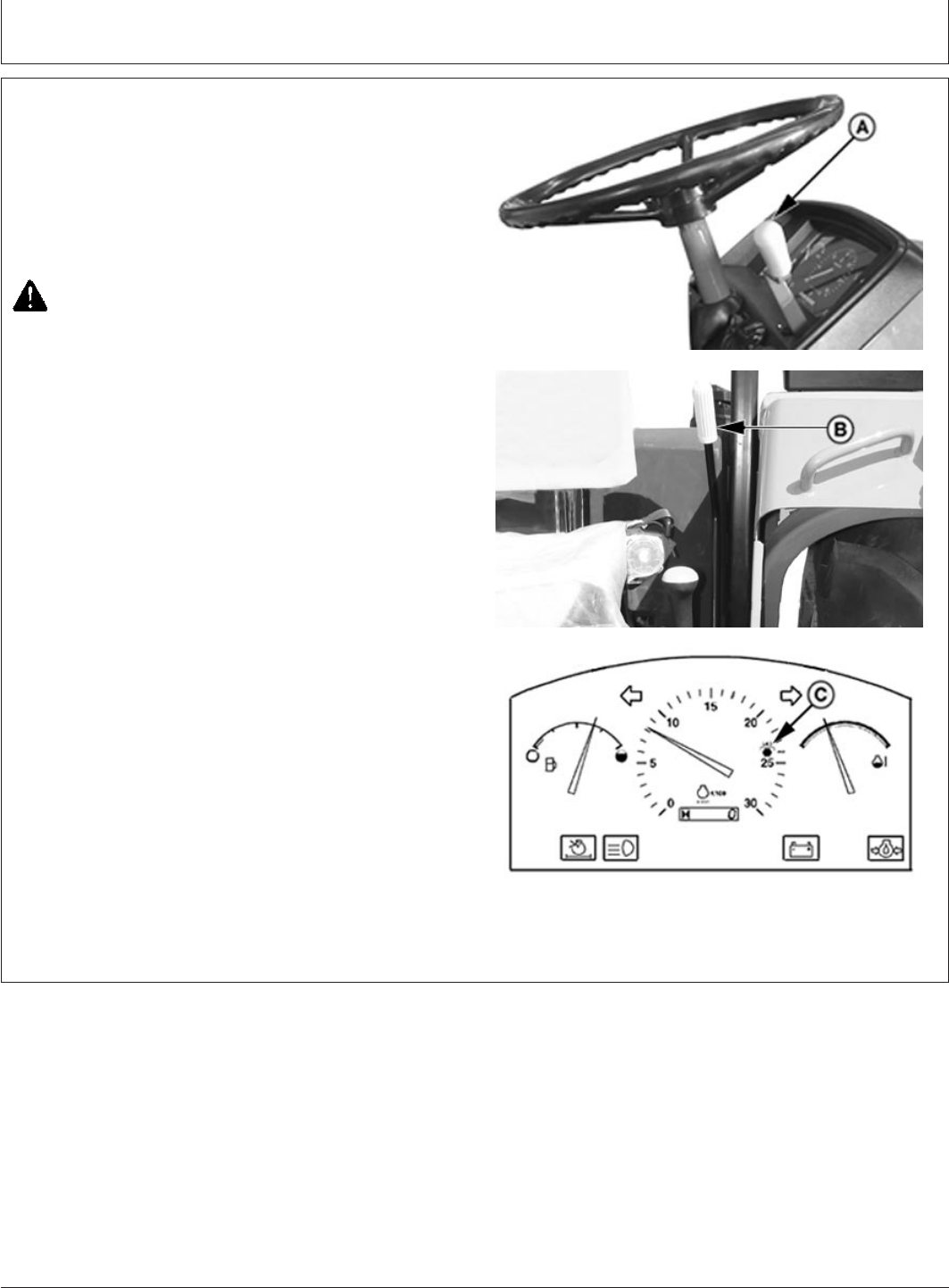
Drawbar and PTO
GENERIC,000005B –19–11JUL06–1/1
Operating Tractor PTO (Standard)
PY4485 –UN–16FEB06PY5534 –UN–22FEB06PY5531 –UN–22FEB06
A—Hand Throttle Lever
B—PTO Shift Lever
C—540 Operation Speed
1. Start engine and push hand throttle lever (A) forward
until tachometer indicates PTO rated speed 2400 RPM
(C) for standard 540 operation.
2. Move control lever (B) forward to engage PTO.
CAUTION: Turn key OFF to stop engine, put
tractor in park position and make sure all
mechanisms have stopped before cleaning out
machine or making any adjustments to PTO
driven implement.
3. Pull control lever back to disengage PTO.
65-3
082206
PN=66
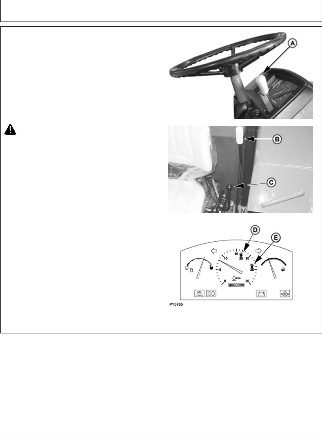
Drawbar and PTO
GENERIC,000005C –19–02JUN06–1/1
Operating Tractor Dual PTO (Optional)
PY4485 –UN–16FEB06PY5535 –UN–22FEB06PY5765 –UN–02JUN06
A—Hand Throttle Lever
B—PTO Lever
C—Economy PTO Lever
D—540E Operation Speed
E—540 Standard Operation Speed
1. Start engine and push hand throttle lever (A) forward
until tachometer indicates PTO rated speed 1782 RPM
(D) for 540E operation or 2400 RPM (E) for standard
540 operation.
2. Move control lever (B) forward to engage PTO.
3. Move control lever (C) forward for economical 540
operation and backward for 540 standard operation.
CAUTION: Turn key OFF to stop engine, put
tractor in park position and make sure all
mechanisms have stopped before cleaning out
machine or making any adjustments to PTO
driven implement.
4. Pull control lever back to disengage PTO.
65-4
082206
PN=67
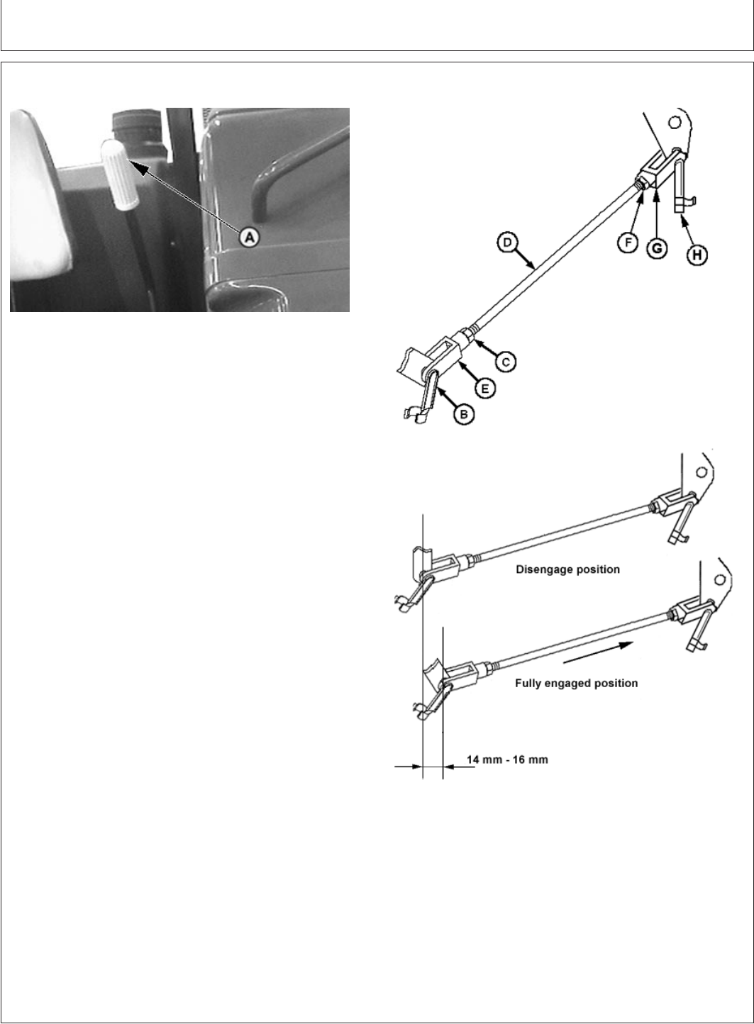
Drawbar and PTO
PY80265,05I0162 –19–20FEB06–1/1
Adjusting PTO Clutch Operating Rod
PY4487 –UN–17FEB06
PY5016 –UN–21MAY05PY5019 –UN–21MAY05
PTO Clutch Rod (In Fully Engaged Position)
A—PTO Clutch Lever
B—Clip Pin
C—Jam Nut
D—Arm
E—Clevis
F—Jam Nut
G—Clevis
H—Clip Pin
1. Move PTO lever (A) to rearward (disengaged) position.
2. Remove clip pin (B) from rear end of clevis (E).
3. Remove clip pin (H) from forward end of clevis (G).
4. Check for equal thread engagement at clevis (G).
Loosen jam nuts (F) and (C). Turn rod (D) until threads
on each side of clevis are equal. Tighten jam nut (F).
5. Loosen jam nut (C) from rear of front clevis (E).
6. Adjust length of arm (D) so the clip pin (B) can be
inserted with the rod pulled forward and the arm pulled
rearward to eliminate free play. Lengthen rod by turn of
the clevis to provide PTO clutch lever free play and
PTO clutch rod travel in fully engaged position to
specification.
Specification
PTO Clutch Lever—Free Play 15 mm........................................................
PTO Clutch Rod (In Fully
Engaged Position)—Travel 14 mm -16 mm................................................
NOTE: Adjust clevis (G) if you cannot make proper
adjustment with clevis (E).
7. Reinstall clip pin (B & H) in clevis (E & G) respectively
and arm (D).
8. Tighten jam nut (C) at clevis.
65-5
082206
PN=68

Ballast
PY80265,05I0163 –19–12SEP05–1/1
Planning for Maximum Productivity
Proper ballasting is an important factor in tractor
performance. maximum productivity can be achieved
only if tractor weight is appropriate for the job.
John Deere FMO (Fundamentals of Machine
Operations) Tractors, discusses methods of
determining correct tractor weight and ballast selection.
FMO-Machinery Management includes information on
tractor and implement matching and increasing
productivity. .
Your John Deere dealer can assist you with
information on these subjects.
PY80265,05I0164 –19–12SEP05–1/1
Selecting Ballast Carefully
Match amount of ballast needed for each job. What is
right for one job may be wrong for another job. Ballast
for traction and stability.
Factors determining amount of ballast:
•Soil surface-loose or firm.
•Type of implement-integral/semi-integral or towed.
•Travel speed-slow or fast.
•Tractor power output-partial or full load.
•Tyres-single, oversize, or dual.
PY80265,05I0165 –19–12SEP05–1/1
Matching Ballast to Load Work
Use no more ballast than necessary, and remove
ballast when it is no longer needed.
Rather than weighing tractor down to pull heavy loads,
try to reduce load. Pulling a lighter load at a higher
speed is more economical and more efficient.
The best way to check for correct ballast is to measure
amount of travel reduction (% slip) of the drive wheels.
Under normal field conditions, travel reduction should
be 10—15 percent.
Add more weight to drive wheels if slip is excessive. If
there is less than 10 percent slip, weight should be
removed.
Too Little Ballast Too Much Ballast
1. Excessive wheel slip 1. Increased load
2. Power loss due to 2. Power loss due to
churning soil carrying extra weight
3. tyre wear 3. tyre strain
4. Fuel waste 4. Soil compaction
5. Lower productivity 5. Fuel waste
6. Lower productivity
70-1
082206
PN=69
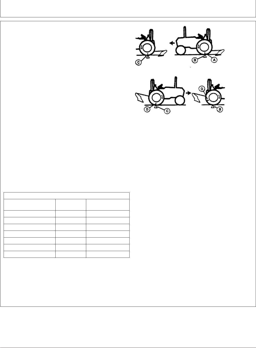
Ballast
PY80265,05I0166 –19–21FEB06–1/1
Measuring Wheel Slip—Manually
PY5516 –UN–17FEB06
1. Place a mark (A) on a rear tyre which is easily
observed (a chalk mark is recommended).
2. With tractor working and implement lowered, mark a
starting point (B) on the ground at the place where the
tyre mark (A) meets the ground.
3. Mark the ground again where the tyre mark (A)
completes 10 full revolutions (C).
4. With implement raised return in the opposite direction.
At the second mark on the ground (C) remark the tyre
(D).
5. While driving the tractor along the same path
(implement raised), count the tyre revolutions required
to reach the starting point (B).
6. Use the return tyre revolutions count and “Wheel
Slippage Chart” to determine slippage. 10—15 percent
is ideal.
7. Adjust ballast or load to give correct slippage.
NOTE: Available horsepower is greatly reduced when
wheel slip drops below 10 percent.
WHEEL SLIPPAGE CHART
Non-Loaded Wheel Estimated % Recommended Action
Revolutions (Step 5) Slip
10 0 Remove Ballast
9-1/2 5 Remove Ballast
9 10 Proper Ballast
8-1/2 15 Proper Ballast
8 20 Add Ballast
7-1/2 25 Add Ballast
7 30 Add Ballast
70-2
082206
PN=70

Ballast
PY80265,05I0167 –19–12SEP05–1/1
Ballast Limitations
Ballast should be limited by either tyre capacity or
tractor capacity. Each tyre has a recommended
carrying capacity which should not be exceeded (see
Wheels, Tyres and Treads section). If a greater
amount of weight is needed for traction, a larger tyre
should be considered.
Ballast can be added as either liquid or cast iron.
70-3
082206
PN=71
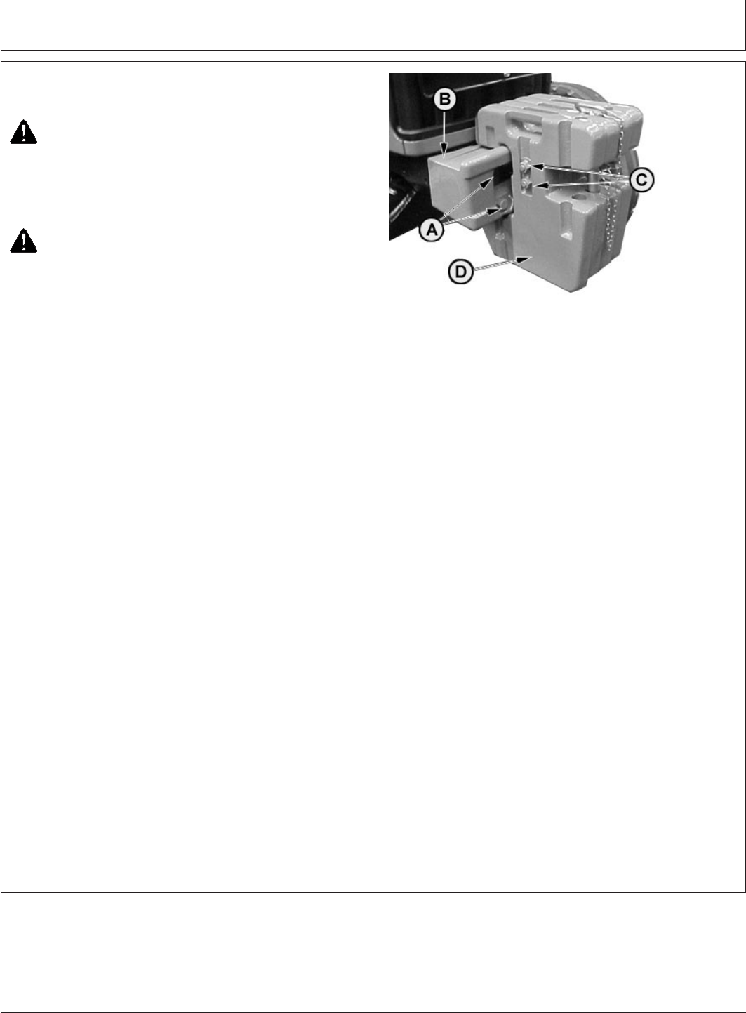
Ballast
PY80265,05I0168 –19–11JUL06–1/1
Ballasting Front End for Transport
PY2246 –UN–21FEB06
A—Attaching Bolts
B—Starter Weight
C—Nuts
D—Additional Weights
CAUTION: Additional front ballast may be
needed for transporting rear-mounted
implements. When implement is raised, drive
slowly over rough ground, regardless of how
much ballast is used.
CAUTION: Weights are heavy. Use proper lifting
equipment. Up to 6 additional weights, 50
Kg(110 lb)each, can be installed on the basic
weight. Approximate weight of starter weight
(A) is : 65 kg (143 lb). Approximate weight of
QUIK-TATCHa
¨weights (D) are 50 kg (110 lb).
Specification
Starter Weight (Ballast)—Weight 65 kg (143 lb) Each...............................
QUIK-TATCHWeight
(Ballast)—Weight 50 kg (110 lb) Each........................................................
IMPORTANT: Tighten the basic weight attaching
screws (A) to 550 N•m (405 lb-ft) and
the screws (C) on front weights (D) to
230 N•m (170 lb-ft).
Installing QUIK-TATCHWeights: QUIK-TATCH
weights can be installed on the front of the tractor.
One starter weight and up to 6 QUIK-TATCHweights
can be installed.
1. Install the basic weight (B) with bolts (A).
2. Place additional weights (D) as required. Secure them
with nuts (C).
QUIK-TATCH is a trademark of Deere & Company
70-4
082206
PN=72

Ballast
PY80265,05I0169 –19–12SEP05–1/1
Ballasting Tractor
Add weight to front end if needed for stability. Heavy
pulling and heavy rear-mounted implements tend to lift
front wheels. Add enough ballast to maintain steering
control and prevent tip-over.
Refer to the implement operator’s manual, along with
“Using Implement Codes” in this section, to determine
the minimum number of front weights that are required
for your tractor model.
PY80265,05I0170 –19–12SEP05–1/1
Determining Maximum Rear Ballast
IMPORTANT: DO NOT overload tyres. If maximum
weight shown in chart is not enough
for safety, reduce load or install
heavier ply tyres.
To extend drive train life, avoid
excessive soil compaction and
rolling resistance, avoid adding too
much ballast. Ballast should never
exceed the weight required to
provide traction for continuous full
power loads in 3rd gear. Remove
ballast if tractor engine labors when
pulling heavy loads in the third
gears.
Chart shows carrying capacity per tyre.
MAXIMUM LOAD PER WHEEL (Aat 19 psi)
Tyre Size Capacity
Bias Ply Tyres Ply Rating kg (lb)
18.4-30 14 2550 (5628)
PY80265,05I0171 –19–12SEP05–1/1
Determining Maximum Front Ballast
Use appropriate front ballast for a particular operating
condition. Two-wheel drive tractors should only have
enough ballast to maintain safe steering control.
Remove ballast when it is no longer needed.
Chart shows carrying capacity per tyre.
IMPORTANT: DO NOT overload tyres. If maximum
weight shown in chart is not enough
for safety, reduce load or install
tyres with a higher load rating.
MAXIMUM LOAD PER WHEEL
2-WD
Capacity
Tyre Size Ply Rating kg (lb)
6.5-20 8 550 (1213)
70-5
082206
PN=73
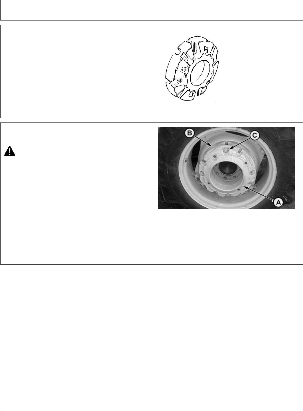
Ballast
PY80265,05I0172 –19–12SEP05–1/1
Using Cast Iron Weights
M47215 –UN–29JAN92
Cast iron weights are available in a 48 kg (106 lb) size.
Weights can be installed on the inside or outside of wheel.
See your John Deere dealer for more information and
recommendations on weight use and placement.
Specification
Cast Iron Weights—Weight 48 kg (106 lb)..................................................
PY80265,05I0173 –19–17FEB06–1/1
Installing Rear Cast Iron Weights
PY1635 –UN–17FEB06
A—Additional Weight
B—Weight
C—Weight Holes
CAUTION: Optional cast iron weight weighs 48
kg (106 lb). Handle with care! Use appropriate
equipment or have the job done by your John
Deere dealer.
1. Attach first weight to wheel disks.
2. To install additional weights (A), install bolts in previous
weight (B). Rotate the added weight to align bolts with
weight holes (C).
3. Tighten attaching bolts securely. Tighten again after a
few hours service. Check tightness regularly.
70-6
082206
PN=74

Ballast
PY80265,05I0174 –19–12SEP05–1/1
Using Liquid Weight
CAUTION: Installing liquid ballast requires
special equipment and training. Have the job
done by your John Deere dealer or a tyre
service store.
IMPORTANT: NEVER fill tyre to more than 75%
full. More solution would leave too
little air space to absorb shocks.
Damage to tyre could occur.
A solution of water and calcium chloride provides safe,
economical ballast. Used properly, it will not damage
Tyres, tubes, or rims.
Use calcium chloride to prevent water from freezing. A
mixture of 0.6 kg per liter (5.0 lb of calcium chloride
per gal) will not freeze solid above —45°C (—53°F).
Charts on this page show how much each tyre size
holds if filled to 75 % full.
LIQUID WEIGHT FOR FRONT Tyres
With 0.6 kg/L (5 lb/gal) Calcium Chloride Solution
Liquid Weight per tyre
Tyre Size kg (lb)—75% Full
6.5-20 34 (74)
LIQUID WEIGHT FOR REAR TYRES
With 0.6 kg/L (5 lb/gal) Calcium Chloride Solution
Liquid weight per Tyre
Tyre Size kg (lb)—75% Full
18.4-30 414 (912)
70-7
082206
PN=75
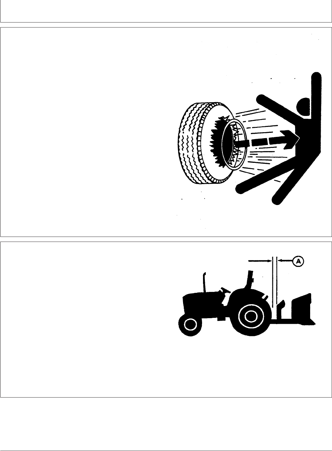
Wheels, Tyres and Treads
PY80265,05I0175 –19–12SEP05–1/1
Service Tyres Safely
TS211 –UN–23AUG88
Explosive separation of at tyre and rim parts can cause
serious injury or death.
Do not attempt to mount a tyre unless you have the
proper equipment and experience to perform the job.
Always maintain the correct tyre pressure. Do not inflate
the tyres above the recommended pressure. Never weld
or heat a wheel and tyre assembly. The heat can cause
an increase in air pressure resulting in a tyre explosion.
Welding can structurally weaken or deform the wheel.
When inflating tyres, use a clip-on chuck and extension
hose long enough to allow you to stand to one side and
NOT in front of or over the tyre assembly. Use a safety
cage if available.
Check wheels for low pressure, cuts, bubbles, damaged
rims or missing lug bolts and nuts.
PY80265,05I0176 –19–12SEP05–1/1
Check Implement-to-Tyre Clearance
M47177 –UN–31JAN92
A—Clearance
IMPORTANT: Check for adequate clearance (A)
between outside diameter of the tyre
and implement with hitch in raised
position.
When large diameter rear tyres are
installed on a tractor with a 3-Point
Hitch, a quick coupler or similar device
may be required to provide adequate
implement-to-tyre clearance.
75-1
082206
PN=76

Wheels, Tyres and Treads
PY80265,05I0177 –19–12SEP05–1/1
Check Tyre Inflation Pressure
Check tyres daily for damage or noticeably low
pressure.
At least every 100 hours of operation, check inflation
pressure with a gauge. Use an accurate gauge having
10 kPa (0.1 bar) (1 psi) graduations.
If tyres contain liquid ballast, use a special air-water
gauge and measure with valve stem at bottom.
NOTE: When furrow plowing or during hillside
operation, tyre pressure can be increased 28
kPa (0.28 bar) (4 psi) ABOVE maximum to
prevent tyre wrinkling or buckling.
IMPORTANT: Always check inflation pressure with
an accurate tyre gauge to prevent
over-inflation. Over-inflation reduces
performance and increases strain of
both tyre and rim.
NOTE: Following inflation information applies to both
front and rear tyres and Tyre Inflation Pressure
Chart.
1. All inflation pressures are calculated for 29 km/h
(18 mph) travel speeds for both diagonal (bias) ply
and radial ply tyres.
2. Operation of tyres at the inflation pressures listed
on chart will result in optimum tractive performance
of the tyre/vehicle system. Correctly inflated radial
tyres will show a large deflection of the sidewall or
“cheeks”. This is normal and will not hurt the tyre if
the inflation pressure is maintained.
3. Inflation pressures less than 80 kPa (12 psi) should
be monitored regularly because of the increased
risk of low pressure air leaks (especially due to
leaking valve cores).
4. Tractors operating on steep side slopes should
increase inflation pressures 28 kPa (4 psi) above
the values listed to compensate for lateral weight
transfer.
5. Tyres run as singles in high traction conditions
sometimes experience bead slip if the bead was not
fully seated or if too much lubricant was used to
mount the tyre. Increasing the inflation pressure will
compensate for this condition but will not cause
reduced traction. Consult your tyre dealer if this
problem occurs.
6. If higher load capacities are needed, contact your
John Deere dealer for tyre manufacturers load and
inflation table information.
75-2
082206
PN=77

Wheels, Tyres and Treads
PY80265,05I0178 –19–12SEP05–1/1
Tyre Inflation Pressure Chart
Tyre Inflation Pressure Chart 5310 S With Maximum Ballast or Heavy
Front Tyres With Little or No Added Weight Mounted Implement
Tyre Size Ply Rating Tread kPa (bar) (psi) kPa (bar) (psi)
6.5-20 8 F2 140 (1.4) (20) 200 (1.9) (29)
With Maximum Ballast or Heavy
Rear Tyres With Little or No Added Weight Mounted Implement
Tyre Size Ply Rating Tread kPa (bar) (psi) kPa (bar) (psi)
18.4-30 14 R1 97 (0.97) (14) 131 (1.31) (19)
PY80265,05I0179 –19–12SEP05–1/1
Tighten Wheel/Axle Hardware Correctly
CAUTION: NEVER operate tractor with a
loose rim, wheel, hub, or axle.
Any time hardware is loosened, tighten to specified
torque.
NOTE: Follow checking procedure when a new tractor
is first used, or wheels have been off.
1. After driving tractor about 100 m (109 yd), and
before placing it under load, tighten hardware to
specified torque.
2. Check hardware after working three hours and
again after 10 hours.
3. Check all hardware frequently and keep it tight.
75-3
082206
PN=78
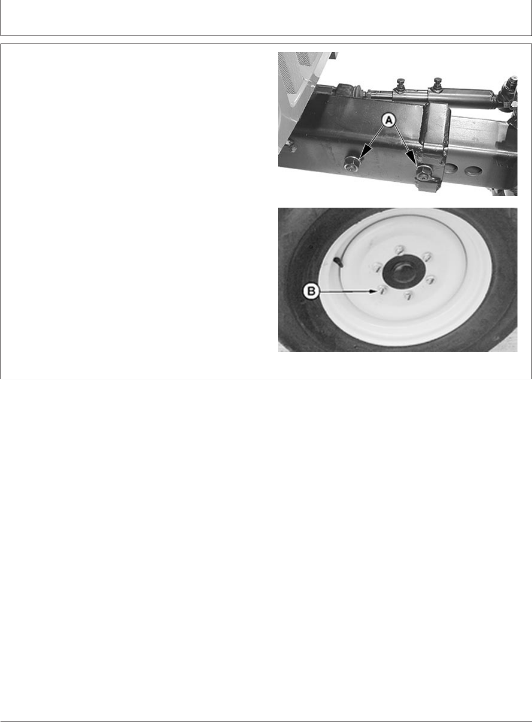
Wheels, Tyres and Treads
GENERIC,0000056 –19–21FEB06–1/1
Tighten Bolts—Adjustable Front Axle
PY5528 –UN–21FEB06PY1487 –UN–18JAN06
A—Axle-to-knee
B—Disk-to-flange
Tighten bolts in the following locations to specifications:
Specification
Adjustable Front Axle—
Axle-to-Knee Bolts—Torque 480 N•m (350 lb-ft)........................................
Adjustable Front Axle—
Disk-to-Flange Bolts—Torque 210 N•m (155 lb-ft).....................................
75-4
082206
PN=79
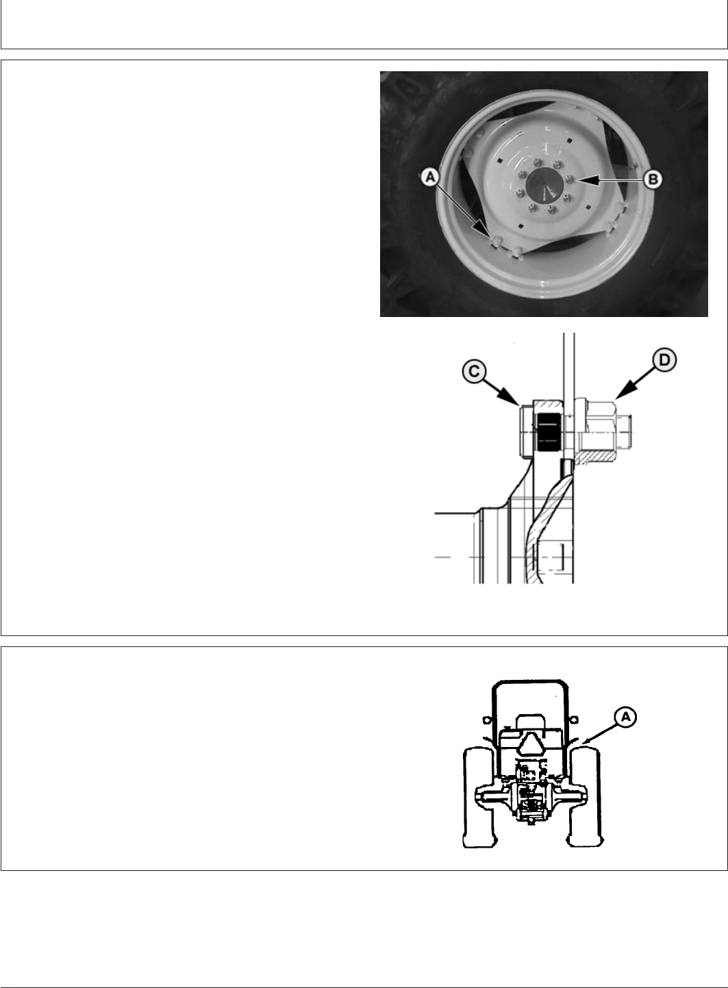
Wheels, Tyres and Treads
PY80265,05I0181 –19–12SEP05–1/1
Tighten Bolts—Rear Axle
PY4282 –UN–06DEC04PY1956 –UN–12JAN04
A—Rim-to-disk bolts
B—Disk-to-flange bolts
C—Stud
D—Nut
Tighten bolts in the following locations to specifications:
Specification
Rear Axle Rim-to-Disk—Torque 245 N•m (180 lb-ft)..................................
Rear Axle Disk-to-Flange—
Torque 550 N•m (406 lb-ft).........................................................................
PY80265,05I0182 –19–12SEP05–1/1
Observe Rear Wheel Tread Width Limitations
M47179 –UN–31JAN92
IMPORTANT: Tyres must have at least 25 mm (1 in.)
clearance with fenders (A) and fuel
tank. When large diameter rear tyres are
installed, check clearance between tyre
and fenders .
75-5
082206
PN=80
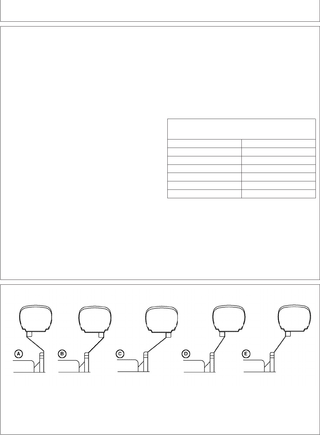
Wheels, Tyres and Treads
PY80265,05I0183 –19–12SEP05–1/2
Tread Settings—Multi-Position Rear Wheels
Wheel tread on rear axle with multi-position wheels
can be adjusted by repositioning or exchanging the
rims or by reversing the wheel disks.
Wheel tread can also be adjusted by exchanging the
complete wheel to the opposite side of the tractor (This
maneuver permits the change from disk-dished-in to
disk-dished-out operations without disassembling the
wheel). When changing rear wheels from one side to
the other, the arrow on side wall of tyre points in the
direction of forward rotation.
The relationship of the wheel disk and rim in obtaining
the different tread settings is shown in the diagrams on
the facing page.
A study of these diagrams, before attempting to
change tread settings, will save unnecessary labor.
IMPORTANT: After setting wheel spacing, tighten
rim-to-disk and disk-to-flange bolts.
Drive tractor 100 m (109 yd) and
tighten again.
Specification
Multi-Position Rear Wheels
Rim-to-Disk—Torque 245 N•m (180 lb-ft)............................................
Multi-Position Rear Wheels
Disk-to-Flange—Torque 550 N•m (406 lb-ft)........................................
NOTE: Tread settings are measured at bottom of
centerline.
STEEL DISKS
REAR TREAD WIDTH
Centerline-to-Centerline
Diagram Tyre Sizes
18.4-30
A 1379 mm (54.3 in.)
B 1475 mm (58.1 in.)
C 1579 mm (62.2 in.)
D 1678 mm (66.1 in.)
E 1782 mm (70.2 in.)
PY80265,05I0183 –19–12SEP05–2/2
IN227 –UN–24MAY00
75-6
082206
PN=81
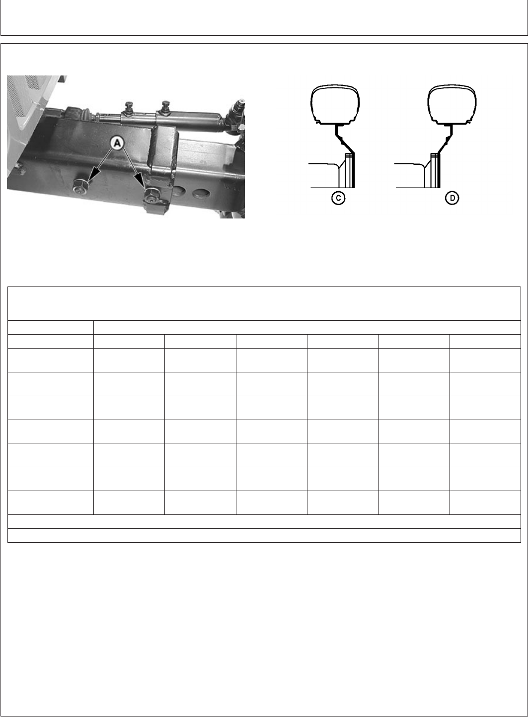
Wheels, Tyres and Treads
GENERIC,0000057 –19–21FEB06–1/2
Tread Settings—Adjustable Front Axle
PY5528 –UN–21FEB06
LV1515 –UN–05MAR96
A—Adjustment Holes
Front rims are offset. With some tires, this provides
two tread spacings at each axle setting.
ADJUSTABLE FRONT AXLE TREAD SETTINGS
Diagram C
Centerline-to-Centerline
Tread Position
a
Tire 123456
1449 mm 1549 mm 1649 mm 1749 mm 1849 mm 1949 mm
6.50-20 (57.0 in.) (61.0 in.) (64.9 in.) (68.9 in.) (72.8 in.) (76.7 in.)
1449 mm 1549 mm 1649 mm 1749 mm 1849 mm 1949 mm
7.50-16 (57.0 in.) (61.0 in.) (64.9 in.) (68.9 in.) (72.8 in.) (76.7 in.)
1468 mm 1568 mm 1668 mm 1768 mm 1868 mm 1968 mm
9.5L-15 (57.8 in.) (61.7 in.) (65.7 in.) (69.6 in.) (73.5 in.) (77.5 in.)
1468 mm 1568 mm 1668 mm 1768 mm 1868 mm 1918 mm
10.0-15 (57.8 in.) (61.7 in.) (65.7 in.) (69.6 in.) (73.5 in.) (75.5 in.)
1473 mm 1573 mm 1673 mm 1773 mm 1873 mm 1973 mm
11L-15 (58.0 in.) (61.9 in.) (65.9 in.) (69.8 in.) (73.7 in.) (77.7 in.)
INT
b
1546 mm 1646 mm 1746 mm 1846 mm 1946 mm
27/9.5-15 (60.9 in.) (64.8 in.) (68.7 in.) (72.7 in.) (76.6 in.)
1477 mm 1577 mm 1677 mm 1777 mm 1877 mm 1977 mm
27/12LL-15 (58.1 in.) (62.1 in.) (66.0 in.) (70.0 in.) (73.9 in.) (77.8 in.)
a
Tread position 1 is with axle adjustment at its most inward location. See Adjust Front Axle Tread Width in this section.
b
Interference (Do not use)
75-7
082206
PN=82
Continued on next page

Wheels, Tyres and Treads
GENERIC,0000057 –19–21FEB06–2/2
ADJUSTABLE FRONT AXLE TREAD SETTINGS
Diagram D
Centerline-to-Centerline
Tread Position
a
Tire 123456
1583 mm 1683 mm 1783 mm 1883 mm 1983 mm 2083 mm
6.50-16 (62.3 in.) (66.3 in.) (70.2 in.) (74.1 in.) (78.1 in.) (82.0 in.)
1583 mm 1683 mm 1783 mm 1883 mm 1983 mm 2083 mm
7.50-16 (62.3 in.) (66.3 in.) (70.2 in.) (74.1 in.) (78.1 in.) (82.0 in.)
1549 mm 1649 mm 1749 mm 1849 mm 1949 mm 2049 mm
9.5L-15 (61.0 in.) (64.9 in.) (68.9 in.) (72.8 in.) (76.7 in.) (80.7 in.)
1549 mm 1649 mm 1749 mm 1849 mm 1949 mm 2049 mm
10.0-15 (61.0 in.) (64.9 in.) (68.9 in.) (72.8 in.) (76.7 in.) (80.7 in.)
1554 mm 1654 mm 1754 mm 1854 mm 1954 mm 2054 mm
11L-15 (61.2 in.) (65.1 in.) (69.1 in.) (73.0 in.) (76.9 in.) (80.9 in.)
1527 mm 1627 mm 1727 mm 1827 mm 1927 mm 2027 mm
27/9.5-15 (60.1 in.) (64.1 in.) (68.0 in.) (71.9 in.) (75.9 in.) (79.8 in.)
1559 mm 1659 mm 1759 mm 1859 mm 1959 mm 2059 mm
27/12LL-15 (61.4 in.) (65.3 in.) (69.3 in.) (73.2 in.) (77.1 in.) (81.1 in.)
a
Number 1 position is with axle adjustment at its most inward location. See Adjust Front Axle Tread Width in this section.
75-8
082206
PN=83

Wheels, Tyres and Treads
GENERIC,0000058 –19–22FEB06–1/1
Adjust Front Axle Tread Width
PY5529 –UN–21FEB06
A—Tie Rod
B—Axle Nuts (4 used)
C—Cap Screws (4 used)
D—Sleeve (4 used)
E—Tie Rod Cap Screw
IMPORTANT: DO NOT place jack under engine oil
pan.
1. Jack up front end of tractor.
2. When making large tread adjustments, loosen cap
screws (E) and adjust the tie rod (A) length with axle
length.
3. Remove two nuts (B), sleeves (D), and cap screws (C)
from front axle (2 on each side).
4. Slide axle knees to desired position. Both sides should
be adjusted to same spacing.
5. Install sleeves (if equipped), cap screws and nuts on
each side. Tighten cap screws to specification.
Specification
Adjustable Front Axle-to-Knee
Bolts—Torque 400 N•m (295 lb-ft)..............................................................
6. Set toe-in. See Check and Adjust Toe-In for your axle
type.
75-9
082206
PN=84
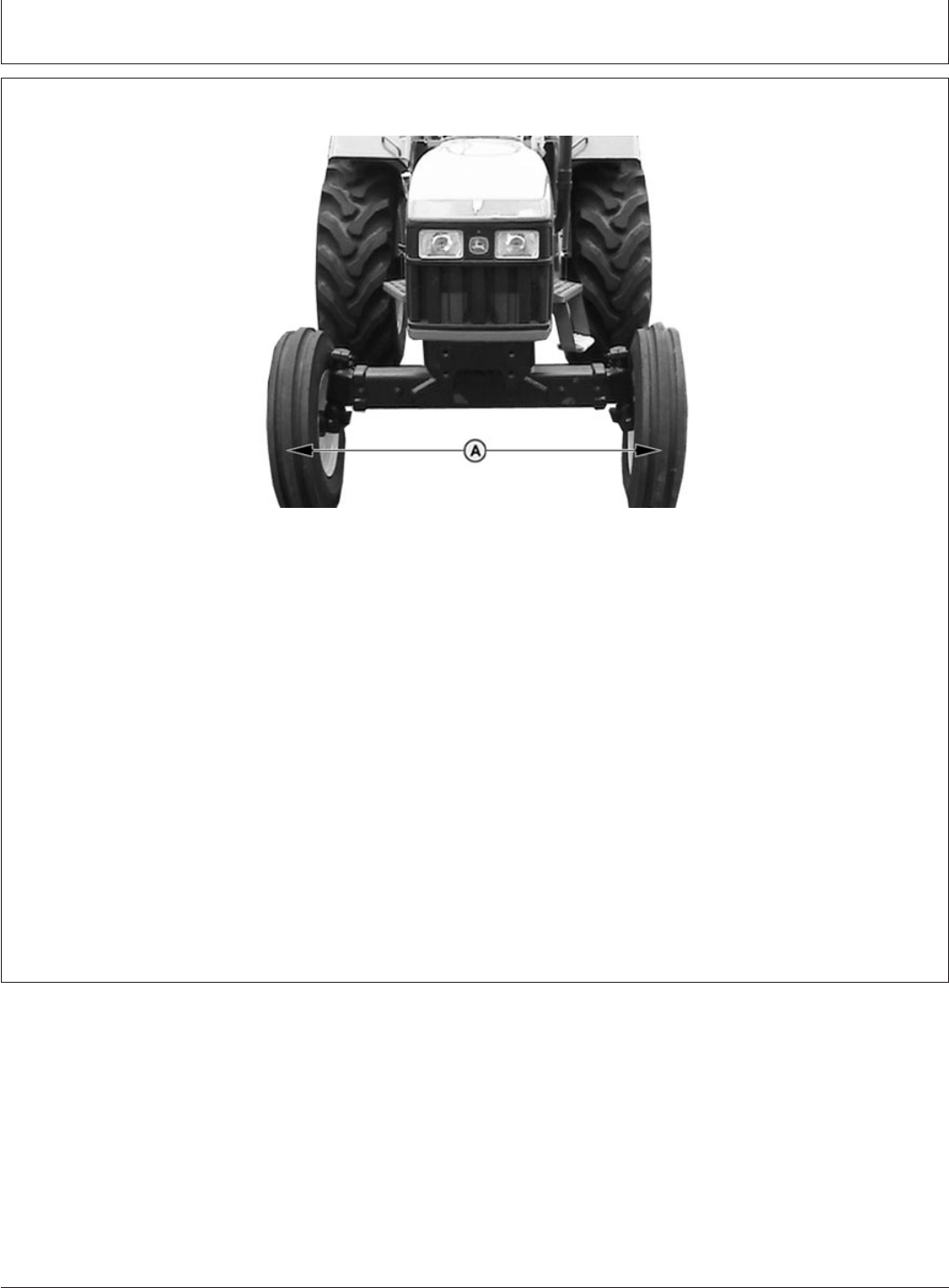
Wheels, Tyres and Treads
PY80265,05I0186 –19–12SEP05–1/1
Checking Toe-In
PY4033 –UN–22JUL04
A—Front Axle Toe-In Distance
1. Park machine on level surface.
2. Turn steering wheel so front wheels are in the
straight-ahead position. Stop engine.
3. Measure distance (A) between tyres at hub level in
front of axle. Record measurement and mark the
tyres.
4. Move tractor back about1m(3ft), so mark is at
hub level behind the axle. Again, measure distance
between tyres at same point on tyre. Record
measurement.
5. Determine the difference between front and rear
measurements. If the front measurement is smaller,
toe is “in”. If the rear is smaller, toe is “out”.
6. Distance (A) at front of tyres should be 3—6 mm
less than distance measured for at rear of tyres.
Adjust toe-in if necessary. (See procedure in this
section.)
75-10
082206
PN=85
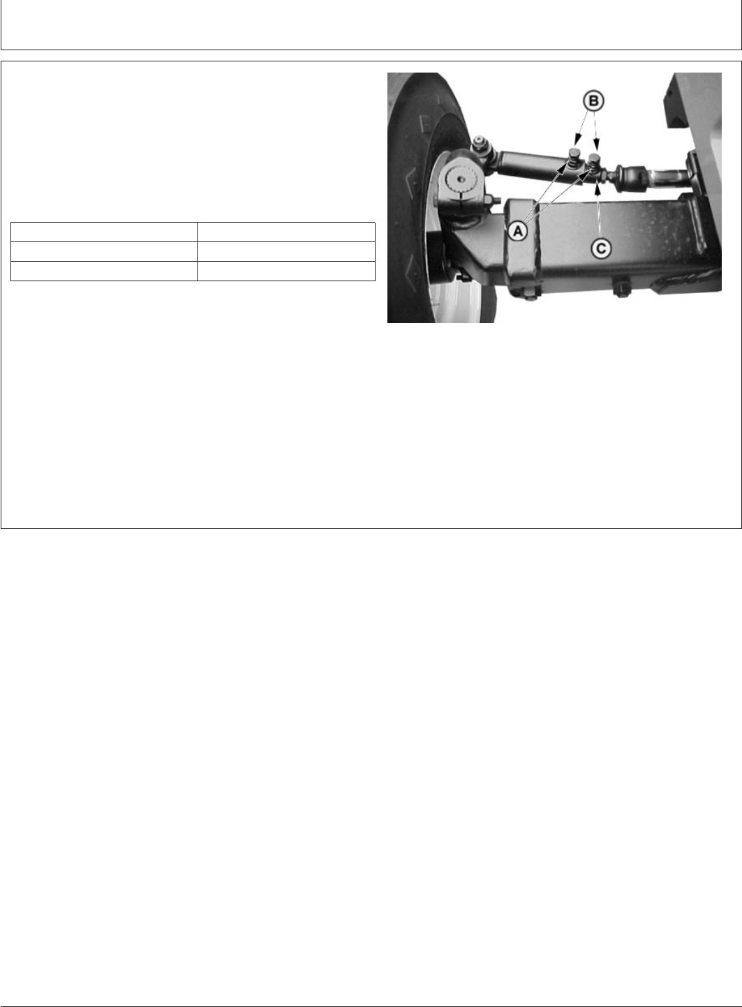
Wheels, Tyres and Treads
PY80265,05I0187 –19–11JUL06–1/1
Adjusting Toe-In
PY4009 –UN–14JUL04
A—Lock Nuts
B—Tie Rod Bolts
C—Inner Tube
1. Loosen lock nuts (A) and back out the bolts (B) on tie
rod tubes several turns.
2. Adjust tie rods on both sides of the tractor equally by
rotating the inner tube (C) to lengthen or shorten tie
rod. Adjust toe-in to 3 to 6 mm (1/8 to 1/4 in.)
Tie Rod Rotation Approximate Change in Toe-in
1/2 turn 8 mm (5/16 in.)
1 turn 16 mm (5/8 in.)
3. Tighten bolts (B) to specification. Do not overtighten as
damage to the tube may occur.
Specification
Tie Rod Bolts—Torque 85 N•m (62 lb-ft)....................................................
4. Tighten the lock nuts (A) to specification.
Specification
Tie Rod Lock Nuts—Torque 90 N•m (66 lb-ft)...........................................
75-11
082206
PN=86
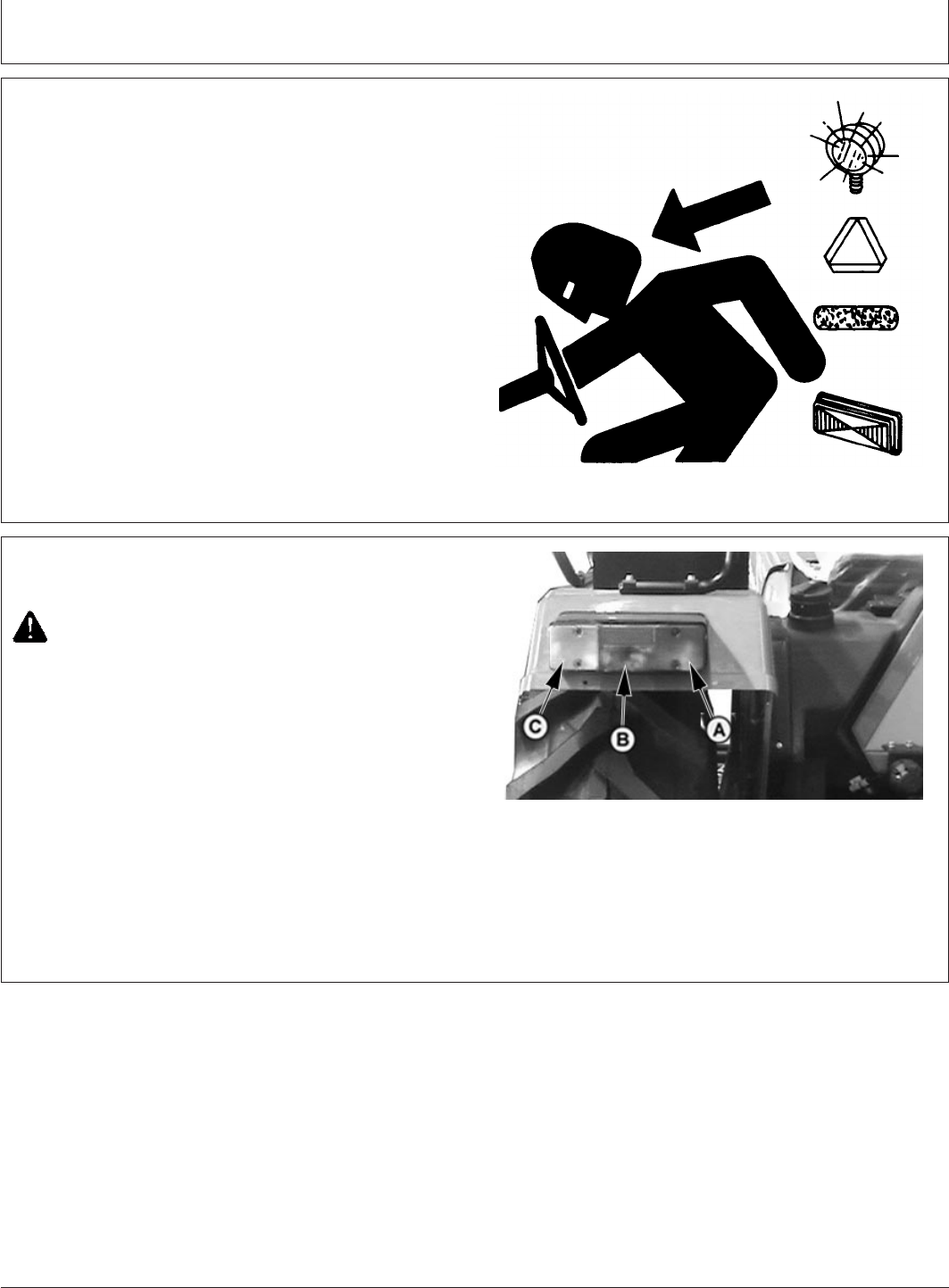
Transporting
PY80265,05I0188 –19–12SEP05–1/1
Use Safety Lights and Devices
TS951 –UN–12APR90
Prevent collisions between other road users, slow moving
tractors with attachments or towed equipment, and
self-propelled machines on public roads. Frequently check
for traffic from the rear, especially in turns, and use hand
signals or turn signal lights.
Use headlights, flashing warning lights, and turn signals
day and night. Follow local regulations for equipment
lighting and marking. Keep lighting and marking visible
and in good working order. Replace or repair lighting and
marking that has been damaged or lost.
PY80265,05I0189 –19–11JUL06–1/5
Driving Tractor on Roads
PY4883 –UN–22APR05
A—Tail Light
B—Reflex Reflector
C—Turning Lights
CAUTION: Observe the following precautions
when operating on a road.
1. Before operating tractor on highway be sure tail lights
(A) and flashing turning lights (C) work properly. Install
and use Slow Moving Vehicle (SMV) emblem and
equipment as required for safety and by local
regulations.
Continued on next page
80-1
082206
PN=87
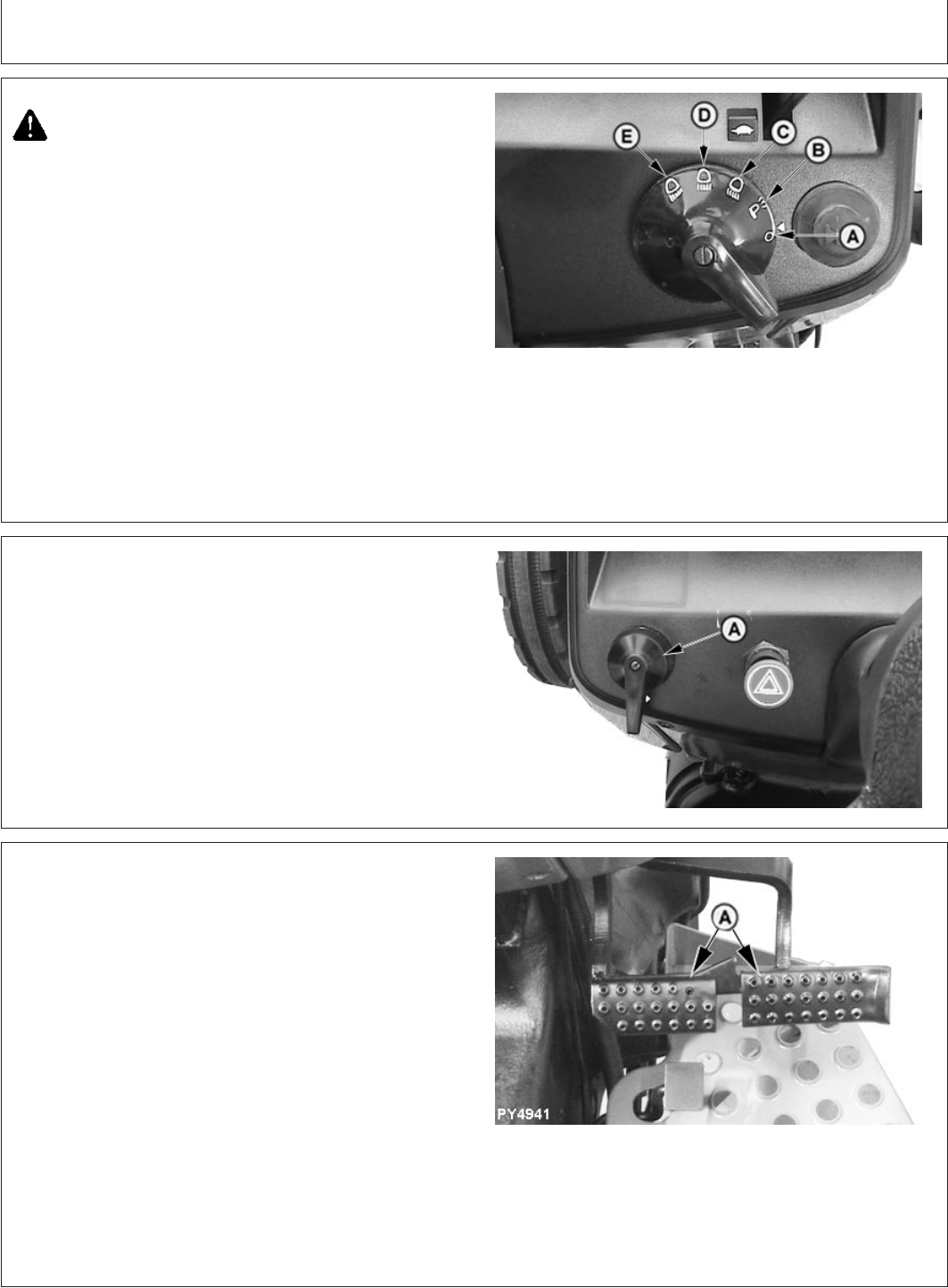
Transporting
PY80265,05I0189 –19–11JUL06–2/5
PY4106 –UN–23FEB06
A—Lights OFF
B—Parking Lights
C—Dim Headlights
D—Bright Headlights
E—High Beamlight
CAUTION: NEVER operate flood lampwhen
transporting tractor. Clear bright light at the
rear of the tractor could confuse drivers of
other vehicles as they approach from the rear.
IMPORTANT: Refer to Lights section for detailed
descriptions of lighting operations and
functions.
2. Turn light switch to high beam headlights or low beam
headlights position. Never use bright lights which are
visible from the rear. Always dim headlights before
meeting another vehicle. Keep headlights properly
adjusted.
PY80265,05I0189 –19–11JUL06–3/5
PY4114 –UN–23FEB06
A—Turn Signal Lever
3. Use turn signals when turning. Be sure to return
control lever (A) to center position after turning.
PY80265,05I0189 –19–11JUL06–4/5
PY4941 –UN–01JUN06
A—Brake Pedals
4. Couple brake pedals (A) together before driving on a
road. Avoid hard applications of brakes.
5. Drive slowly enough to maintain safe control at all
times. Slow down for hillsides, rough ground, and
sharp turns, especially when transporting heavy,
rear-mounted equipment.
6. Before going down a hill, shift to a gear low enough to
control speed without using brakes. Never coast down
hill.
7. When transporting downhill on icy or graveled grades,
be alert for skids which could result in loss of steering
control. To decrease chance of skids, reduce speed
and be sure tractor has proper ballast.
80-2
082206
PN=88
Continued on next page
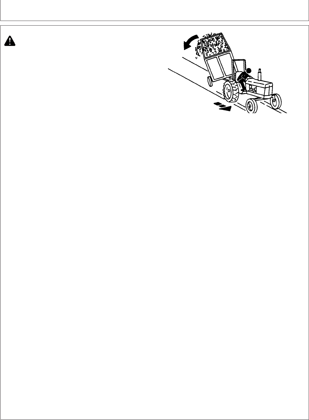
Transporting
PY80265,05I0189 –19–11JUL06–5/5
LV4042 –UN–09JUL99
CAUTION: Stopping distance increases with
speed and weight of towed loads, and on
slopes. Towed loads with or without brakes that
are too heavy for the tractor or are towed too
fast can cause loss of control. Consider the
total weight of the equipment and its load.
Observe these recommended maximum road
speeds, or local speed limits which may be
lower:
If towed equipment does not have brakes, do
not travel more than 32 km/h (20 mph) and do
not tow loads more than 1.5 times the tractor
weight.
If towed equipment has brakes, do not travel
more than 40 km/h (25 mph) and do not tow
loads more than 4.5 times the tractor weight.
Ensure the load does not exceed the
recommended weight ratio. Add ballast to
recommended maximum for tractor, lighten the
load, or get a heavier towing unit. The tractor
must be heavy and powerful enough with
adequate braking power for the towed load. Use
additional caution when towing loads under
adverse surface conditions, when turning, and
on inclines.
8. Use caution when operating tractor at transport
speeds. Reduce speed if towed load weighs more than
tractor and is not equipped with brakes. (See Towed
Equipment operator’s manual for recommended
transport speeds.)
9. Use additional caution when transporting towed loads
under adverse surface conditions, when turning and on
inclines.
10. Heavy towed or rear mounted implements may start
swaying in transport. Excessive swaying will result in
loss of steering control. Drive slowly and avoid quick
turns of steering wheel. Refer to your implement
operator’s manual regarding maximum travel speed
limitations.
80-3
082206
PN=89
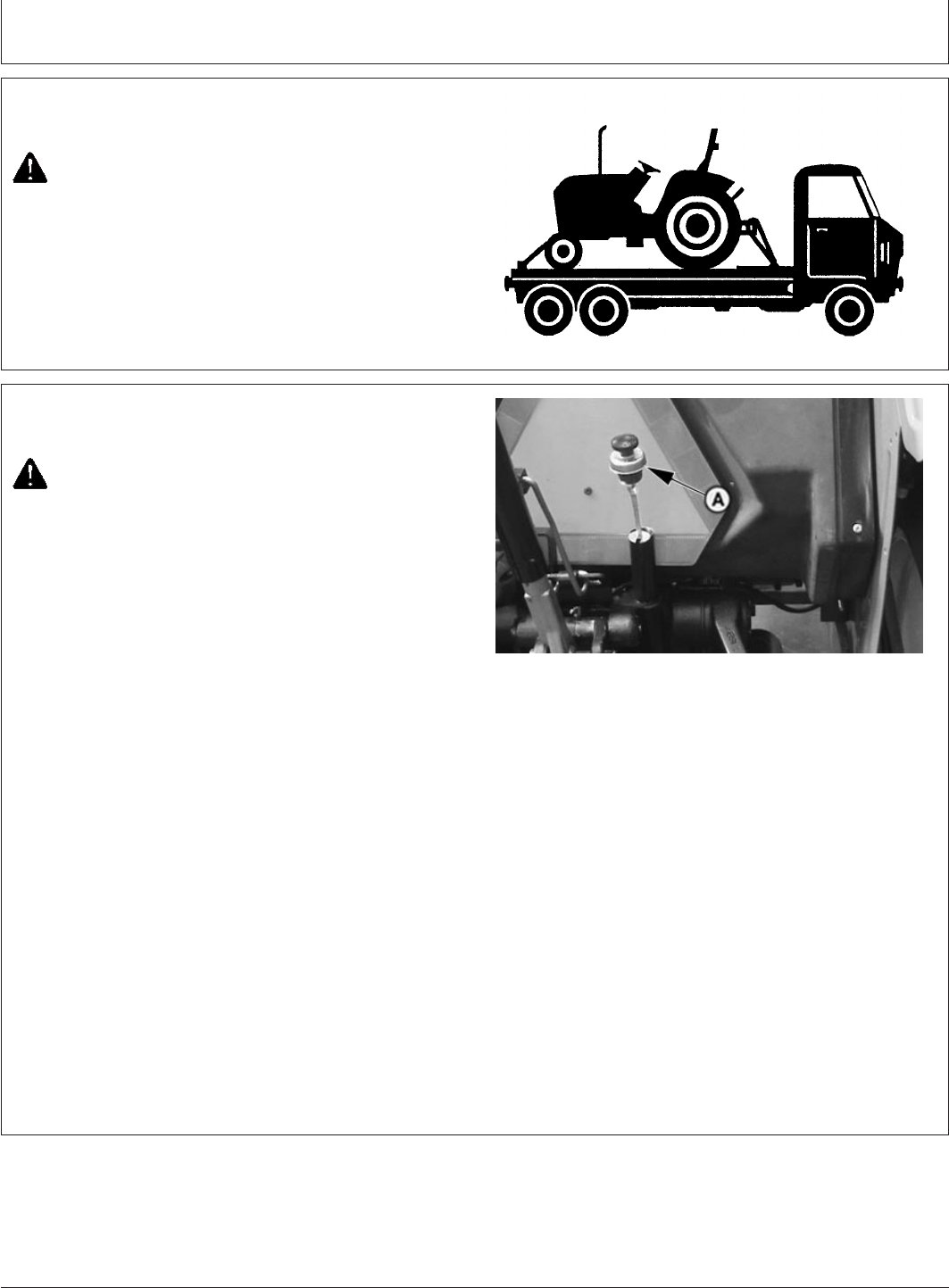
Transporting
PY80265,05I0190 –19–12SEP05–1/1
Transport on Carrier
LV610 –UN–22APR94
CAUTION: Chain tractor to carrier securely.
Drive carrier slowly.
The best method of transporting a disabled tractor is to
haul it on a flatbed carrier.
IMPORTANT: Seal exhaust to prevent dirt from
entering and damaging engine.
PY80265,05I0191 –19–11JUL06–1/1
Towing Tractor
PY4942 –UN–21APR05
A—Dipstick
CAUTION: NEVER tow tractor faster than 16
km/h (10 mph). Have an operator steer and
brake tractor.
IMPORTANT: To avoid damaging
transmission-hydraulic system, observe
the following precautions:
1. Be sure transmission-hydraulic system oil is to the full
level line on dipstick (A). If the tractor is to be towed
with the front wheels raised, add 1 liter of oil to
hydraulic fill port for each 90 mm (3-1/2 in.) the wheels
are raised. DO NOT raise front wheels more than 305
mm (12 in.) above ground.
NOTE: After transporting tractor, drain oil that was added
for towing.
2. Make sure the differential lock is disengaged.
3. Make sure range lever is in neutral and gear lever is in
4th gear.
80-4
082206
PN=90
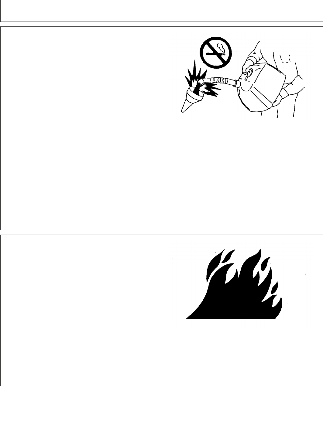
Fuels,LubricantsandCoolant
PY80265,05I0192 –19–12SEP05–1/1
Handle Fuel Safely—Avoid Fires
M73115 –UN–09MAR90
Use only diesel fuel.
Handle fuel with care, it is highly flammable.
DO NOT refuel machine:
•While you smoke.
•When machine is near open flame or sparks.
•When engine is running. STOP engine.
Fill fuel tank outdoors.
Help prevent fires:
•Clean oil, grease and dirt from machine.
•Clean up spilled fuel immediately.
Do not store machine with fuel in tank in a building where
fumes may reach an open flame or spark.
PY80265,05I0193 –19–12SEP05–1/1
Handle Fluids Safely—Avoid Fires
TS227 –UN–23AUG88
When you work around fuel, do not smoke or work near
heaters or other fire hazards.
Store flammable fluids away from fire hazards. Do not
incinerate or puncture pressurized containers.
Make sure machine is clean of trash, grease, and debris.
Do not store oily rags; they can ignite and burn
spontaneously.
85-1
082206
PN=91

Fuels, Lubricants and Coolant
GENERIC,000005D –19–22FEB06–1/1
Diesel Engine Oil
PY5149 –UN–21AUG05
Use genuine engine oil. This oil is available in pack of
1litre and 8.5 litre at John Deere Dealership only
PY80265,05I0194 –19–12SEP05–1/1
Fuel Storage
Buy good quality, clean fuel from a reputable supplier.
Proper fuel storage is critically important. Use clean
storage and transfer tanks. Periodically drain water
and sediment from bottom.
Avoid storing fuel over long periods of time.
Store fuel in a convenient place away from buildings.
PY80265,05I0195 –19–12SEP05–1/1
Diesel Fuel
Fuel sulphur content should be less than 1.0 percent
preferably less than 0.5 percent. Diesel fuel having
sulphur content higher than 1.0 percent may cause
increase wear on metal engine parts because of acids
produced by sulphur during combustion.
IMPORTANT: If fuel sulphur content exceeds 0.7
percent, the engine oil drain interval
must be reduced by 50 percent to
125 hours.
Cetane number should be no less than 40 to assure
satisfactory starting and overall performance.
Fitleration of fuel is critical for proper operation of
engine. Use genuine MICO fuel filters. Always change
fuel filter inserts at given interval
85-2
082206
PN=92
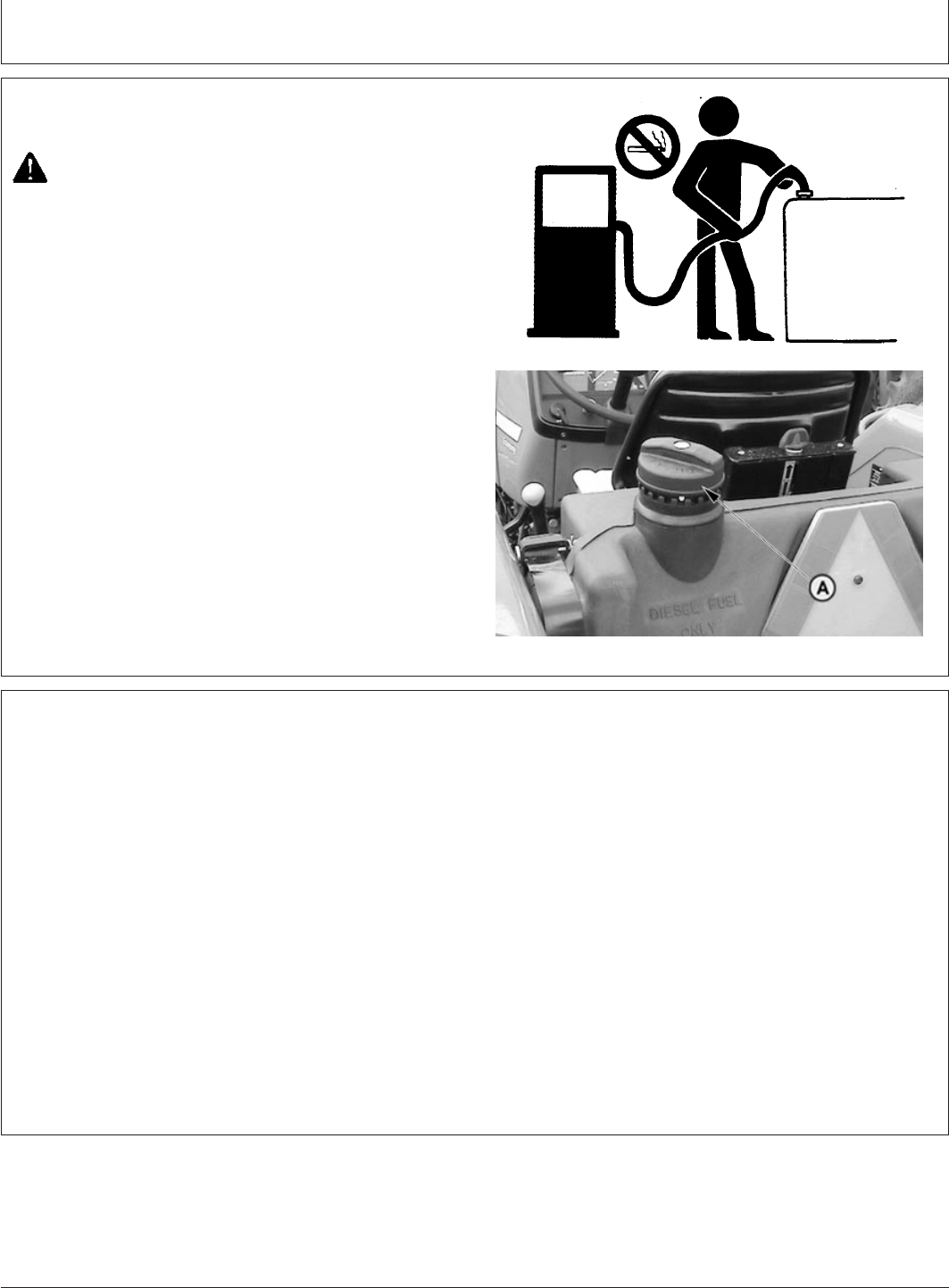
Fuels, Lubricants and Coolant
PY80265,05I0196 –19–12SEP05–1/1
Fill Fuel Tank
TS202 –UN–23AUG88PY4101 –UN–20AUG04
A—Fuel Tank Filler Cap
CAUTION: Handle fuel with care: It is highly
flammable. DO NOT refuel the machine while
smoking or when near open flame or sparks.
Always stop engine before refueling machine.
Fill fuel tank outdoors.
Prevent fires by keeping machine clean of
accumulated trash, grease and debris. Always
clean up spilled fuel.
Fuel tank can be filled through fill cap (A). Fill fuel tank at
end of each day’s operation. This prevents condensation
in tank as moist air cools.
Specification
Fuel Tank—Capacity 68 L..........................................................................
PY80265,05I0197 –19–12SEP05–1/1
Lubricant Storage
Your equipment can operate at top efficiency only
when clean lubricants are used.
Use clean containers to handle all lubricants.
Whenever possible, store lubricants and containers in
an area protected from dust, moisture, and other
contamination. Store containers on their side to avoid
water and dirt accumulation.
Make certain that all containers are properly marked to
identify their contents.
Properly dispose of all old containers and any residual
lubricant they may contain.
85-3
082206
PN=93

Fuels, Lubricants and Coolant
DX,COOL3 –19–27OCT05–1/2
Diesel Engine Coolant
The engine cooling system is filled to provide
year-round protection against corrosion and cylinder
liner pitting, and winter freeze protection to -37°C
(-34°F). If protection at lower temperatures is required,
consult your John Deere dealer for recommendations.
John Deere COOL-GARDPrediluted Coolant is
preferred for service.
John Deere COOL-GARD Prediluted Coolant is
available in a concentration of either 50% ethylene
glycol or 55% propylene glycol.
Additional recommended coolants
The following engine coolant is also recommended:
•John Deere COOL-GARD Coolant Concentrate in a
40% to 60% mixture of concentrate with quality
water.
John Deere COOL-GARD coolants do not require use
of supplemental coolant additives, except for periodic
replenishment of additives during the drain interval.
Other fully formulated coolants
Other fully formulated low silicate ethylene or
propylene glycol base coolants for heavy-duty engines
may be used if they meet one of the following
specifications:
•ASTM D6210 prediluted (50%) coolant
•ASTM D6210 coolant concentrate in a 40% to 60%
mixture of concentrate with quality water
Coolants meeting ASTM D6210 do not require use of
supplemental coolant additives, except for periodic
replenishment of additives during the drain interval.
Coolants requiring supplemental coolant additives
Other low silicate ethylene glycol base coolants for
heavy-duty engines may also be used if they meet one
of the following specifications:
•ASTM D4985 ethylene glycol base prediluted (50%)
coolant
•ASTM D4985 ethylene glycol base coolant
concentrate in a 40% to 60% mixture of concentrate
with quality water
Coolants meeting ASTM D4985 require an initial
charge of supplemental coolant additives, formulated
for protection of heavy duty diesel engines against
corrosion and cylinder liner erosion and pitting. They
also require periodic replenishment of additives during
the drain interval.
Other coolants
It is possible that neither John Deere COOL-GARD nor
coolants meeting one of the coolant standards listed
above is available in the geographical area where
service is performed. If these coolants are unavailable,
use a coolant concentrate or prediluted coolant with a
quality additive package that provides cylinder liner
cavitation protection and protects the cooling system
metals (cast iron, aluminum alloys, and copper alloys
such as brass) from corrosion.
The additive package must be part of one of the
following coolant mixtures:
•ethylene glycol or propylene glycol base prediluted
(40% to 60%) coolant
•ethylene glycol or propylene glycol base coolant
concentrate in a 40% to 60% mixture of concentrate
with quality water
Water quality
COOL-GARD is a trademark of Deere & Company
85-4
082206
PN=94
Continued on next page
Fuels, Lubricants and Coolant
DX,COOL3 –19–27OCT05–2/2
Water quality is important to the performance of the
cooling system. Distilled, deionized, or demineralized
water is recommended for mixing with ethylene glycol
and propylene glycol base engine coolant concentrate.
IMPORTANT: Do not use cooling system sealing
additives or antifreeze that contains
sealing additives.
IMPORTANT: Do not mix ethylene glycol and
propylene glycol base coolants.
PY80265,05I0201 –19–12SEP05–1/1
Use Correct Transmission-Hydraulic Filter
Element
To protect systems, replace transmission-hydraulic oil filter
with a John Deere service filter element. Minimum and
maximum performance specifications are printed on John
Deere filters. Other filters may be used if they meet these
performance specifications.
See Lubrication and Maintenance section for
recommended filter change intervals.
PY80265,05I0202 –19–12SEP05–1/1
Transmission and Hydraulic Oil
PY5149 –UN–21AUG05
Same oil is used for transmission and hydraulic. Use
HY-GARD
transmission-hydraulic oil. This oil is available
in pack of 1litre and 20 litre at John Deere Dealership only
HY-GARD is a trademark of Deere & Company
85-5
082206
PN=95

Fuels, Lubricants and Coolant
PY80265,05I0203 –19–12SEP05–1/1
Grease
Depending upon the expected air temperature range
during the service interval, use grease as shown on
the adjoining table.
John Deere
High-Temperature/Extreme-Pressure/Non-Clay Grease
is recommended.
If other greases are used, they must be greases
meeting SAE Multipurpose High Temperature Grease
with Extreme Pressure (EP) Performance and capable
of operating at compartment temperatures above
150°C (302°F)
At temperatures below —30°C (—22°F), use arctic
greases such as those meeting Military Specification
MIL-G-10942C.
Grease Type Temperature Limits
Arctic Grease Below —10°C (14°F)
SAE(NLGI)#0or#1 0°Cto—30°C (32°Fto—22°F)
SAE (NLGI) #2 50°Cto0°C (122°Fto32°F)
JD High Temperature 50°Cto—10°C (122°Fto14°F)
85-6
082206
PN=96

ServiceandMaintenance
PY80265,05I0204 –19–02JUN06–1/1
Observe Service Intervals
PY5777 –UN–02JUN06
A—Hourmeter
Using hour meter (A) as a guide, perform all services at
the hourly intervals indicated on the following pages. Keep
a service record on charts provided in the Lubrication and
Maintenance Record Charts section.
IMPORTANT: Recommended service intervals are for
average conditions. Service MORE
OFTEN if tractor is operated under
adverse conditions.
PY80265,05I0205 –19–12SEP05–1/1
Break-In Service
IMPORTANT: Keep wheel hardware tight to avoid
tractor damage. Check wheel
hardware torque before operating,
twice during first ten hours of
operation, after fifty hours of
operation, and periodically
thereafter.
During the First 10 Hours of Operation:
Perform daily or 10 hours service. (See Service
Intervals in Lubrication and Maintenance section.)
Tighten wheel hardware. (See Wheels, Tyres, and
Treads section.)
After the First 50 Hours of Operation:
Tighten wheel hardware. (See Wheels, Tyres, and
Treads section.)
Check alternator/fan belt tension and tighten air intake
and cooling system hose clamps
Perform 50 Hours Service
After the First 100 Hours of Operation:
Replace transmission-hydraulic filter element
Change engine oil and filter
1
After the First 1100 Hours of Operation:
Replace transmission-hydraulic oil
1
See Engine Break-In Oil in Service section for additional
information.
90-1
082206
PN=97

Service and Maintenance
PY80265,05I0206 –19–12SEP05–1/1
Service Intervals
Every 10 Hours
•Check engine oil level
•Check coolant level
•Drain water and sediment from fuel filters
•Lubricate tie rod ends
1
•Lubricate steering spindles
1
•Lubricate front axle pivot pin
1
•Lubricate rear axle bearings
1
Every 50 Hours
•Check transmission-hydraulic system oil level
•Clean and check battery
•Inspect all tyres
•Lubricate front axle pivot pin
•Lubricate steering spindles
•Inspect tractor for loose nuts and bolts
First 100 Hours
•Change engine oil and filter
•Replace transmission-hydraulic filter
Every 250 Hours
•Service air cleaner
•Change engine oil and filter
•Clean and check battery
•Inspect and adjust alternator/fan belt
•Lubricate 3-point hitch
•Check neutral start system
•Check clutch pedal free travel
•Check brake pedal adjustment
Every 500 Hours
•Replace fuel filter
•Replace transmission-hydraulic filter
Every 600 Hours
•Clean engine crankcase vent tube
•Repack front wheel bearings
•Check and tighten all hoses and hose clamps
•Check cooling system for leaks
•Lubricate rear axle bearings
•Check engine idle speeds
•Have your John Deere dealer:
-Check front axle pivot pin
-Adjust engine valve clearance
Inspect fuel injectors
First 1100 Hours
•Change transmission-hydraulic oil and filter
Every 1250 Hours
•Change transmission-hydraulic oil and filter
•Clean transmission-hydraulic pickup screen
Annually
•Change engine oil and filter
•Replace air cleaner elements
Every 2 Years or 2000 Hours (Whichever Comes
First)
•Flush cooling system
Service As Required
•Service air cleaner
•Adjust throttle friction
•Drain water and sediment from fuel tank and fuel
filters
1
Only necessary when operating in extremely wet and muddy
conditions.
90-2
082206
PN=98
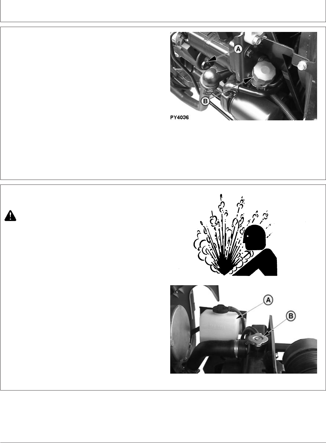
Service—Every 10 Hours
PY80265,05I0207 –19–12JUL06–1/1
Check Engine Oil Level
PY4036 –UN–19JUN06
A—Engine Oil Dipstick
B—Engine Oil Filler Cap
1. Park tractor on level ground, put range shift lever in
neutral (N), set brakes and pull fuel shut-off knob to
stop engine
2. Pull out dipstick (A). Oil level should be between two
marks on dipstick. DO NOT operate engine when oil
level is below low mark on dipstick.
3. If level is low, add oil through oil filler hole (B) until
even with upper mark. DO NOT overfill. (See fuels,
Lubricants and Coolants section.)
PY80265,05I0208 –19–11JUL06–1/1
Check Coolant Level
TS281 –UN–23AUG88PY4121 –UN–07DEC05
A—Coolant Recovery Tank
B—Radiator Cap
CAUTION: . Only remove radiator cap (B) when
engine is cold. Slowly loosen cap to first stop
to relieve pressure before removing completely.
IMPORTANT: Check the coolant level when engine is
cold.
1. Check coolant level in coolant recovery tank (A).
2. Coolant level shall be upto to “Cold Mark”. If it is below
“Cold Mark”, add coolant to that mark only. (See Fuels,
Lubricants and Coolant section.)
95-1
082206
PN=99
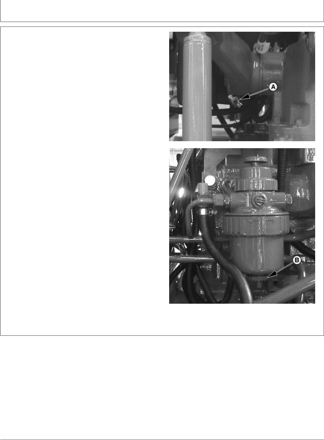
Service—Every 10 Hours
PY80265,05I0209 –19–11JUL06–1/1
Drain Water and Sediment From Fuel Tank
and Fuel Filter
PY4284 –UN–06DEC04PY4283 –UN–06DEC04
A—Fuel Tank Fitting
B—Fuel Filter Drain
NOTE: Place a small container under drain fitting to catch
draining fuel. Dispose of waste properly.
1. Open fuel tank fitting (A) to bleed accumulated
moisture and sediment from the fuel tank. Tighten
fitting closed when clear fuel runs from fitting.
2. Open fuel filter drain (B) to bleed accumulated
moisture and sediment from filter. Tighten drain when
clear fuel runs from drain.
95-2
082206
PN=100
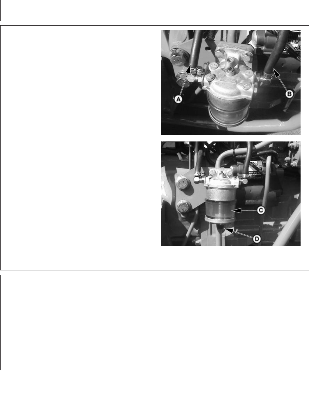
Service—Every 10 Hours
PY80265,05I0210 –19–12SEP05–1/1
Water Separator Bowl
PY4285 –UN–06DEC04PY4300 –UN–06DEC04
A—Hose from Fuel Tank to Water Separator
B—Hose from Water Separator to Fuel Filter
C—Water Separator
D—Drain Screw
1. The water separator is used to obtain the better
functioning of fuel system.
2. Drain water and contaminants from clear water
separator sediment bowl by opening drain screw (D).
PY80265,05I0211 –19–12SEP05–1/1
Lubricate as Necessary
Lubrication required only when operating in extremely
wet and muddy conditions. Lubricate with several
shots of multipurpose grease specified in Fuels,
Lubricants and Coolant section.
•Tie rod ends
•Steering spindles (Front Axle) (See Service—50
Hours)
•Front axle pivot pin (See Service—50 Hours)
•Rear axle bearings (See Service—600 Hours)
•Steering cylinder head.
95-3
082206
PN=101
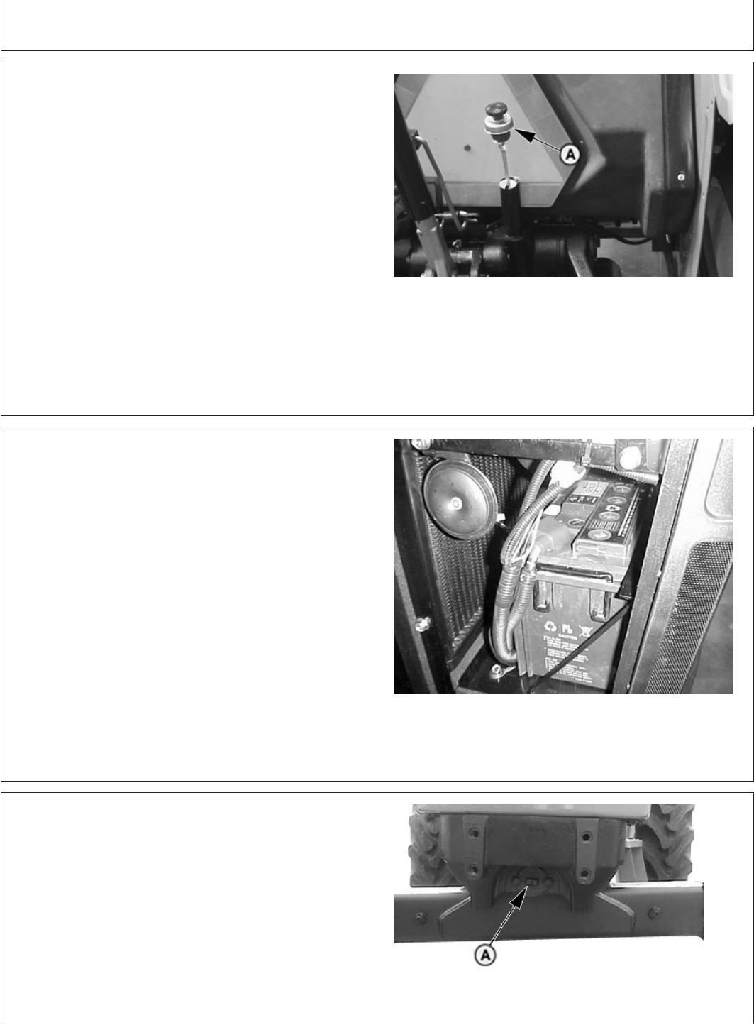
Service—Every 50 Hours
PY80265,05I0212 –19–11JUL06–1/1
Check Transmission-Hydraulic System Oil
Level
PY4942 –UN–21APR05
A—Dipstick
1. Park on level ground. Put range shift lever in neutral
(N), set brakes and pull fuel shut-off knob to stop
engine.
2. Wait a minimum of five minutes for oil to settle.
3. Check level at mark given on dipstick (A). Level should
be to full oil level mark .
4. Add oil to filler port if level is low. (See Anti-Chatter
Transmission/Hydraulic Oil in Fuels, Lubricants and
Coolant section.)
PY80265,05I0213 –19–12SEP05–1/1
Clean and Check Battery
PY1965 –UN–24FEB04
A—Positive Terminal
B—Negative Terminal
To access battery, see procedure in Service section.
Put range shift lever in neutral (N), set brakes and pull
fuel shut-off knob to turn engine OFF. Wipe battery with a
damp cloth. Clean and tighten connections if needed.
Check fluid level in each cell, fill to bottom of filler neck
with clean mineral-free water. (See Servicing Battery in
Service section.)
PY80265,05I0214 –19–11JUL06–1/1
Lubricate Front Axle Pivot Pin
PY4067 –UN–27JAN05
Adjustable Front Axle
A—Adjustable Axle Pivot Pin
Adjustable axle pivot pin (A) also requires lubrication of
the front and rear pivot bushing zerks with multipurpose
grease. (See Fuels, Lubricants and Coolant section).
100-1
082206
PN=102
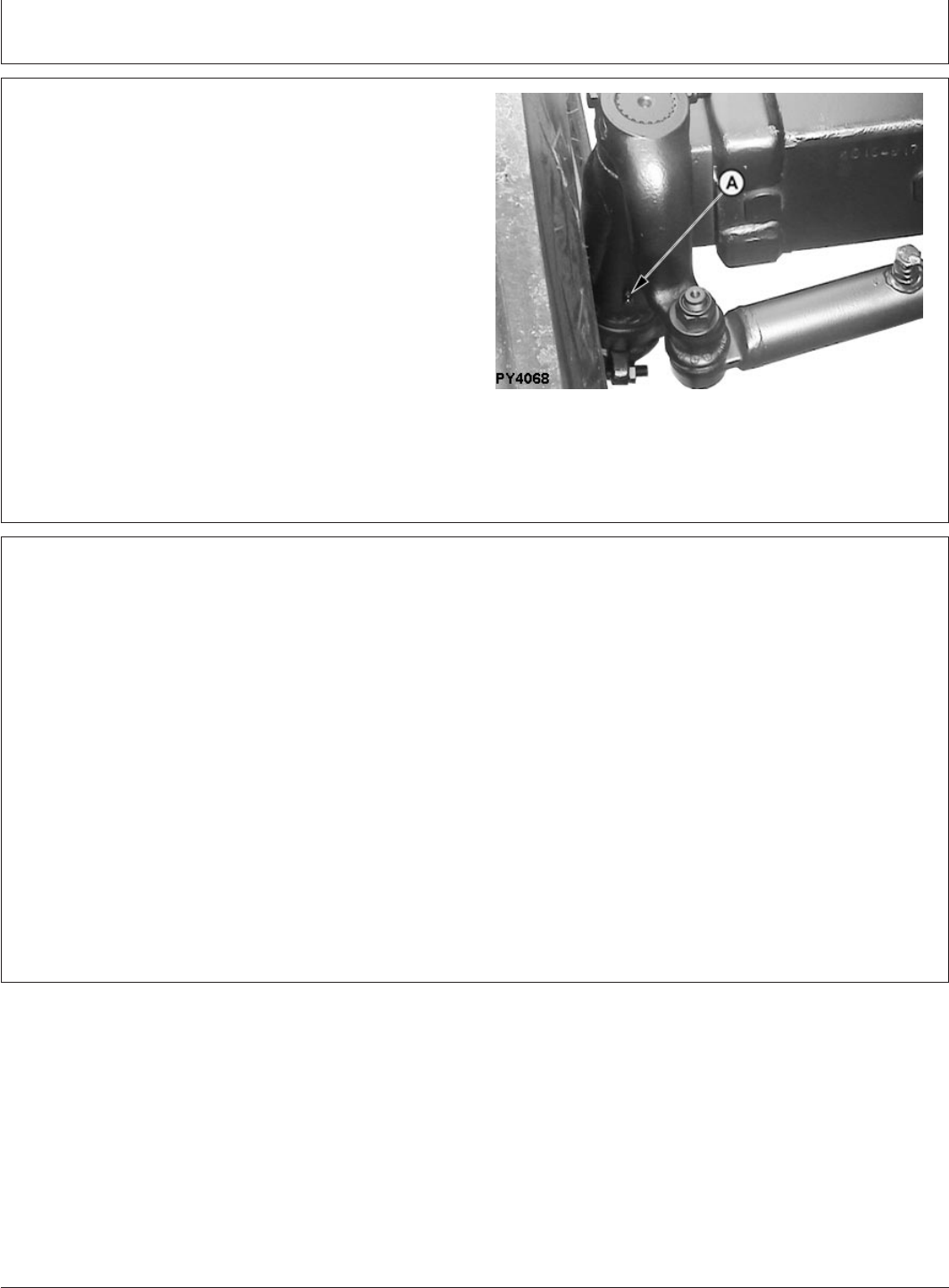
Service—Every 50 Hours
PY80265,05I0215 –19–11JUL06–1/1
Lubricate Steering Spindles
PY4068 –UN–06JUN06
Adjustable Front Axle Shown
A—Spindle Fitting Zerk
On tractors equipped with adjustable front axle, apply
several shots of general purpose grease (See Fuels,
Lubricants and Coolant section) to steering spindle fitting
(A).
GENERIC,000005E –19–22FEB06–1/1
Inspect Tyres and Loose Hardwares
Inspect all tyres and check inflation pressure. Also check
tractor for any loose harware
Item Measurement Specification
Ballast Weights Retaining Bolts Torque 230 N•m (170 lb-ft)
Front Axle Disk-to-Flange Bolts Torque 175 N•m (130 lb-ft)
Rear Axle Rim-to-Disk Bolts Torque 245 N•m (180 lb-ft)
Rear Axle Disk-to-Flange Bolts Torque 550 N•m (406 lb-ft)
100-2
082206
PN=103

Service—Every 250 Hours
PY80265,05I0217 –19–12SEP05–1/1
Change Engine Oil and Filter
PY4147 –UN–26AUG04
A—Engine Oil Drain Plug
B—Engine Oil Filter
1. Run engine to heat oil. pull fuel shut-off knob to turn
engine OFF.
NOTE: The approximate engine crankcase oil capacity is
8.5 L (9 qt).
2. Remove oil drain plug (A) and drain oil.
3. Replace engine oil filter (B) while changing oil. Apply a
film of oil on the new oil filter gasket and install new
filter. Hand tighten plus 1/2 turn.
4. Install drain plug.
IMPORTANT: Change engine oil every 125 hours if
diesel fuel has a sulfur content greater
than 0.7 percent.
5. Add seasonal viscosity grade oil. (See Fuels,
Lubricants and Coolant section.)
Specification
Engine Crankcase Oil—Capacity 8.5 L.......................................................
NOTE: In Break-in-period, change the oil in first 100
hours. Engine oil should be changed annually as
a minimum.
110-1
082206
PN=104
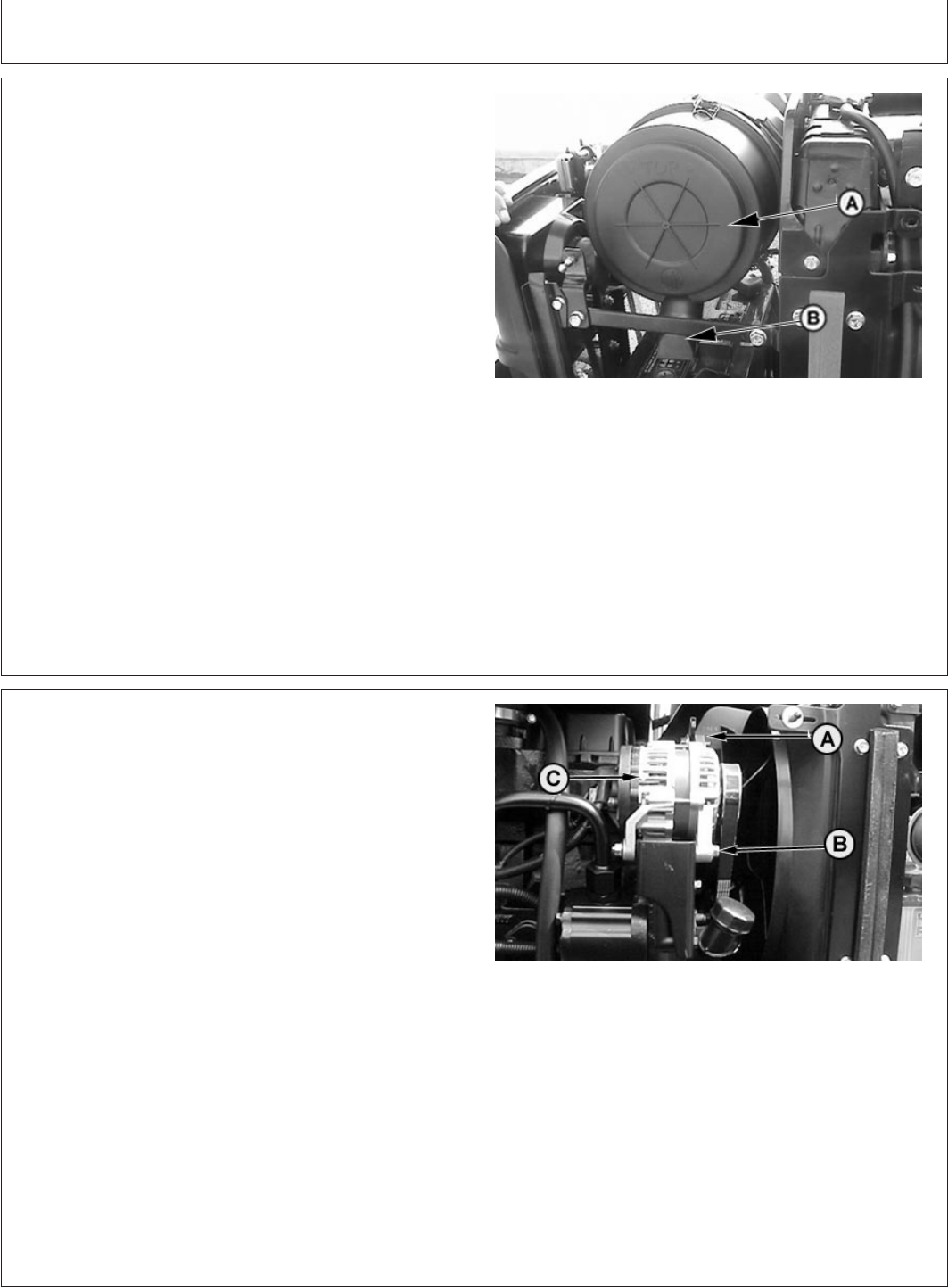
Service—Every 250 Hours
PY80265,05I0218 –19–12SEP05–1/1
Service Air Cleaner
PY4286 –UN–06DEC04
A—Air Cleaner
B—Dust Unloader Valve
A dual element air cleaner is standard. A dirty primary
element is indicated when the air restriction indicator on
instrument panel illuminates. A dirty element can result in
loss of power or excessive smoke.
IMPORTANT: Check unloader valve (B) frequently.
Empty as often as needed to keep it
from filling with dust. If valve is allowed
to fill with dust, air cleaner element will
plug rapidly.
Service air cleaner (A) when indicator light illuminates,
every 250 hours or at least once a year.
Replace primary element at least one a year.
The secondary element should be removed only when
being replaced, normally once a year.
See procedure in Removing Air Cleaner Elements in
Service section.
PY80265,05I0219 –19–12SEP05–1/1
Inspect and Adjust Alternator/Fan Belt
PY1652 –UN–27OCT03
A—Tension Adjustment Cap Screw
B—Alternator Mounting Bolt
C—Alternator Frame
Replace if worn or damaged. (See procedure in Service
section.)
NOTE: Run engine for five minutes to warm a cold belt.
Let a hot belt cool for 15 minutes before
adjustment.
Check tension by pressing belt midway between pulleys.
Belt should deflect about 19 mm (3/4 in.) at 89 N (20 lb
force).
IMPORTANT: Pry against alternator frame only
Adjust tension by loosening cap screw (A) and mounting
bolt (B). Apply force to alternator frame (C) until belt
tension is correct. Tighten cap screw and bolt.
110-2
082206
PN=105
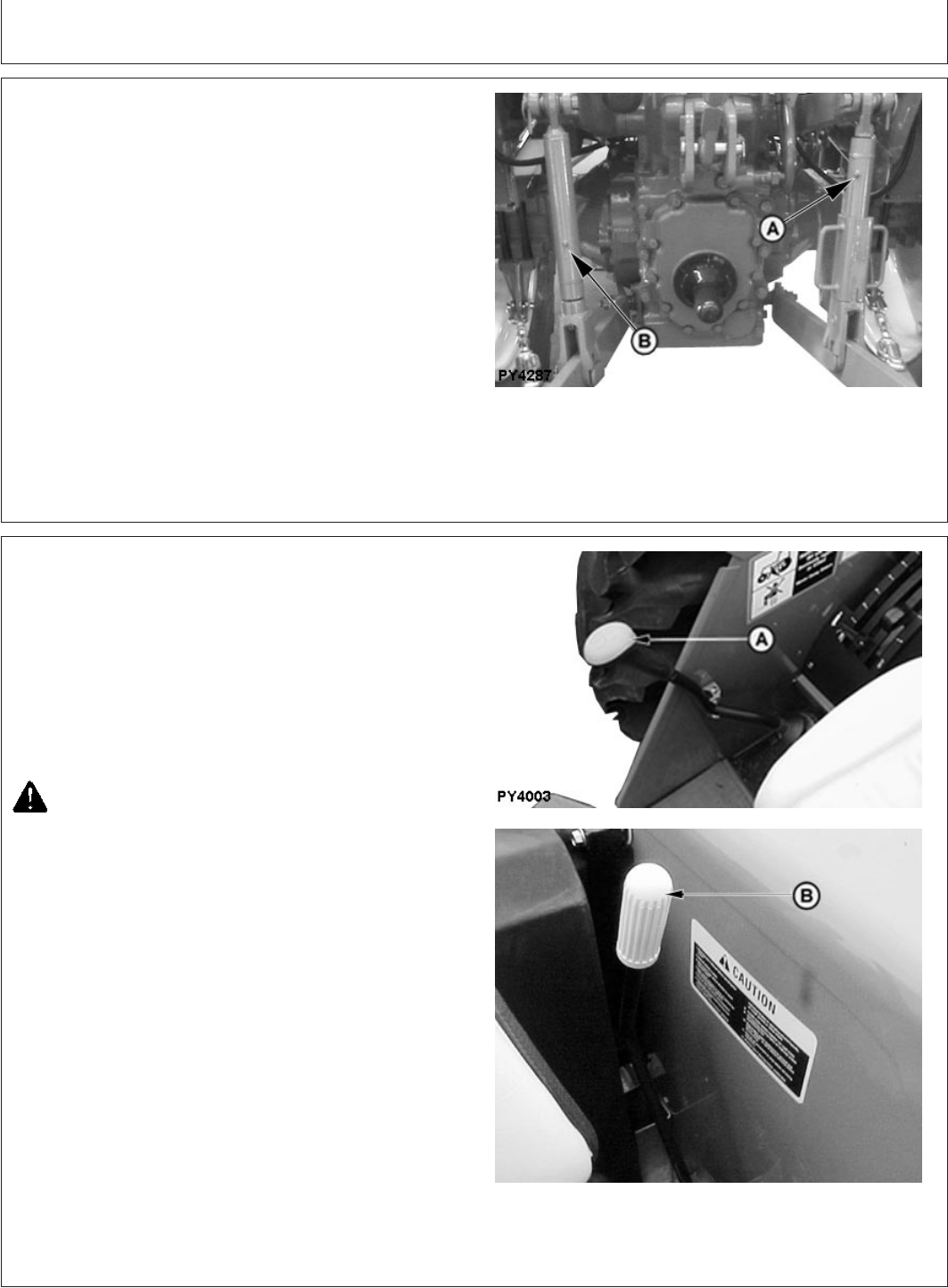
Service—Every 250 Hours
PY80265,05I0220 –19–12SEP05–1/1
Lubricate 3-Point Hitch
PY4287 –UN–01JUN06
A—Right Lift Link Grease Fittings (2 used)
B—Left Lift Link Grease Fitting
Lubricate right lift link (A) and left lift link (B) with several
shots of multipurpose grease. (See Fuels, Lubricants and
Coolant section.)
PY80265,05I0221 –19–12JUL06–1/1
Check Neutral Start System
PY4003 –UN–01JUN06PY4012 –UN–14JUL04
A—Gear Shift Lever
B—PTO Shift Lever
Your John Deere tractor is equipped with interlocks to
prevent inadvertent movement when the engine is started.
Turning the key switch with the clutch pedal depressed
should crank the engine if all of the following conditions
exist:
•Gear shift lever (A) in NEUTRAL
CAUTION: If starter turns engine in any of the
following steps, have the neutral start system
repaired by your John Deere dealer.
Turning the key switch to the start position should NOT
start the engine, if either of the following exist:
•Gear shift lever (A) in gear (not in NEUTRAL)
•PTO lever (B) in engaged position
110-3
082206
PN=106
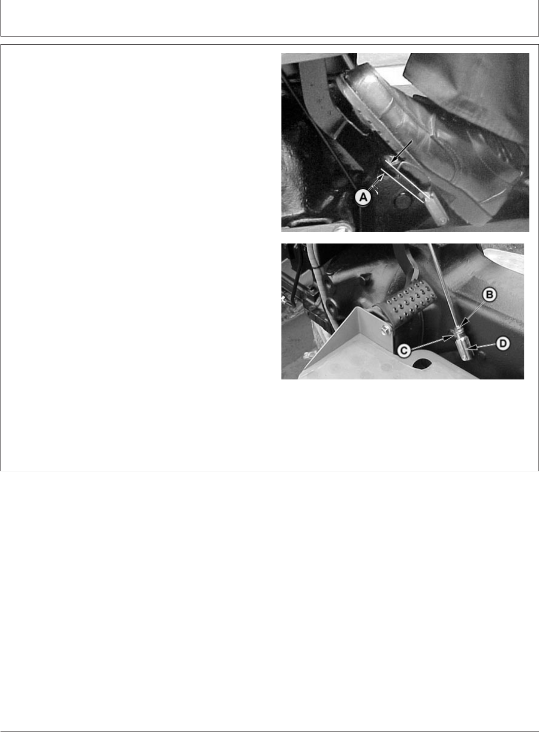
Service—Every 250 Hours
PY80265,05I0222 –19–21JUN06–1/1
Check and Adjust Clutch Pedal Free Play
PY1502 –UN–02JUN05
PY4013 –UN–02JUN05
A—Clutch Pedal Free Play
B—Lock Nut
C—Clip Pin
D—Clevis
Measure free play (A) at top of pedal stroke. Adjust
linkage to obtain 20 to 25 mm free play.
To adjust linkage, loosen lock nut (B), unlatch the
connecting clip pin (C) and remove. Rotate clevis (D).
After making adjustment, replace clip, and recheck free
play. When free play is correct, tighten lock nut.
110-4
082206
PN=107
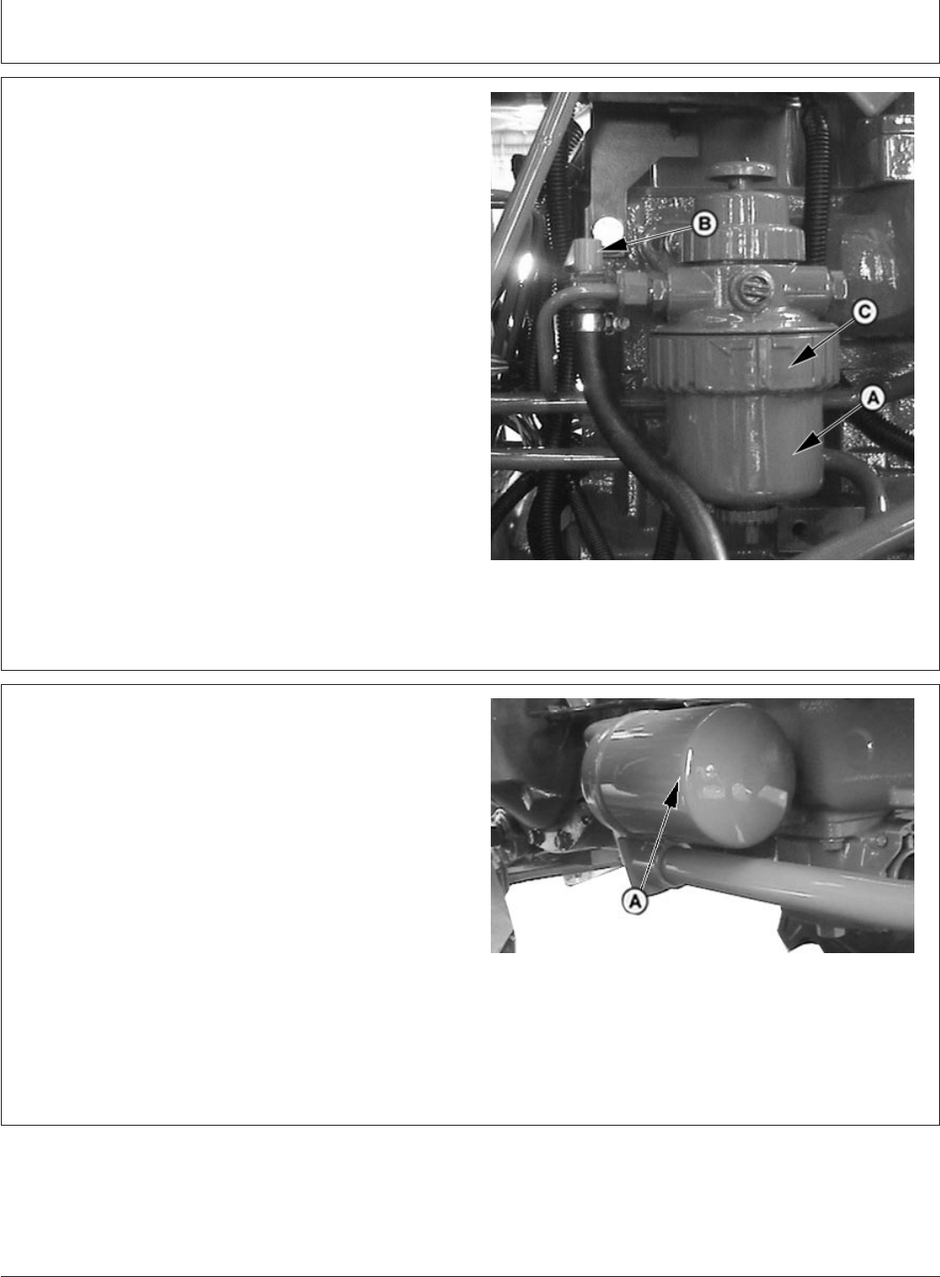
Service—Every 500 Hours
PY80265,05I0223 –19–12SEP05–1/1
Replace Fuel Filter
PY4288 –UN–06DEC04
A—Fuel Filter Element
B—Fuel Shut-off
C—Retaining Ring
Replace Filter element (A) at least once a year.
1. Close fuel shut-off (B).
2. Remove retaining ring (C) and filter.
3. Install new filter with retaining ring hand tight.
4. Open fuel shut-off and bleed air from filter. (See
Bleeding Fuel System in Service section).
PY80265,05I0224 –19–12SEP05–1/1
Replace Transmission-Hydraulic Filter
PY4407 –UN–22FEB06
A—Transmission-Hydraulic Oil Filter
1. Remove filter (A). Apply a film of oil to new gasket and
install new filter. Hand tighten plus 1/2 turn.
2. Run engine several seconds and recheck
transmission-hydraulic oil level.
3. Add transmission-hydraulic oil if required (See Fuels,
Lubricants and Coolant section).
NOTE: In Break-in-period, change the trans-hydra oil filter
in first 100 hours.
115-1
082206
PN=108
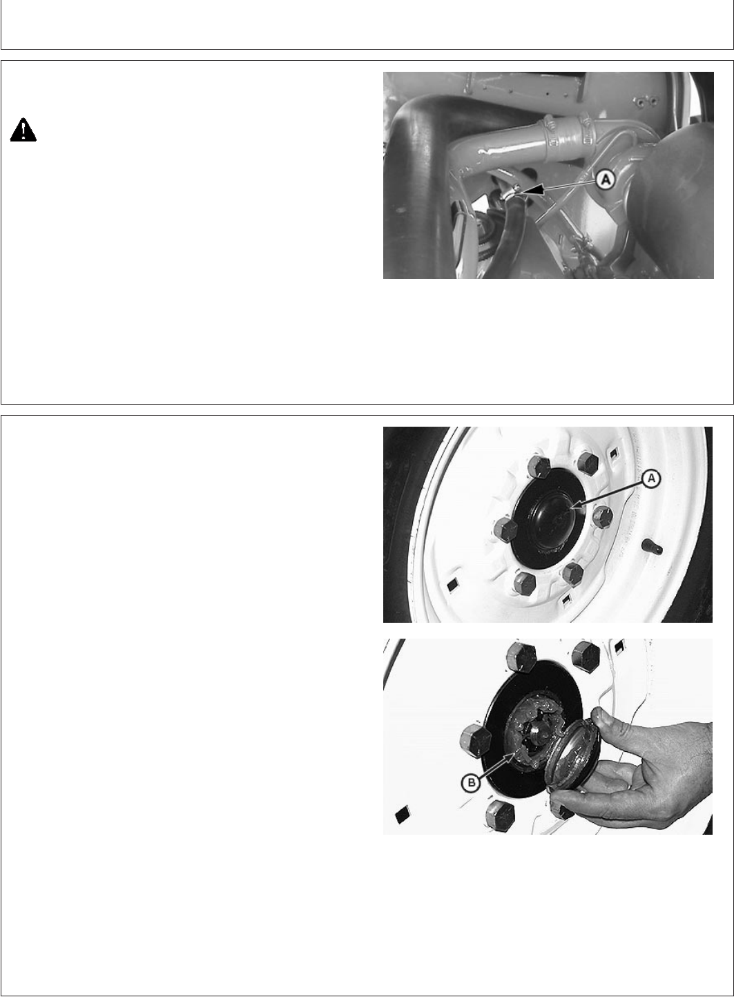
Service—Every 600 Hours
PY80265,05I0225 –19–12SEP05–1/1
Clean Engine Crankcase Vent Tube
PY4289 –UN–06DEC04
A—Crankcase Vent Tube
CAUTION: Reduce compressed air to less than
210 kPa (2 bar) (30 psi) when using for cleaning
purposes. Clear area of bystanders, guard
against flying chips, and wear personal
protection equipment including eye protection.
Remove crankcase vent tube (A) from engine. Wash in
solvent or blow clean with compressed air. Reassemble
vent tube breather cap to engine. Be sure vent tube is not
kinked or pinched.
PY80265,05I0226 –19–12SEP05–1/1
Pack Front Wheel Bearings
LV4410 –UN–06OCT99LV4411 –UN–06OCT99
A—Hub Cap
B—Pack Bearing with Grease
1. Jack up front end of tractor..
2. Remove hub cap, cotter pin, and wheel nut.
3. Remove washer and wheel bearings. Clean all parts in
solvent and blow dry with compressed air. Replace any
worn or damaged parts.
4. Pack bearing with multipurpose grease. (See Fuels,
Lubricants and Coolant section.) Coat seal with same
grease.
5. Reinstall bearings, washer, and wheel nut.
6. Tighten wheel nut until a slight drag is felt when hub is
turned. Back nut off just enough to install cotter pin in
hole in wheel spindle.
7. Reinstall hub cap and wheels. Tighten lug bolts to 175
N•m (130 lb-ft). Retighten bolts after driving tractor 100
m (109 yds) and again after 3 hours and 10 hours use.
115-1
082206
PN=109
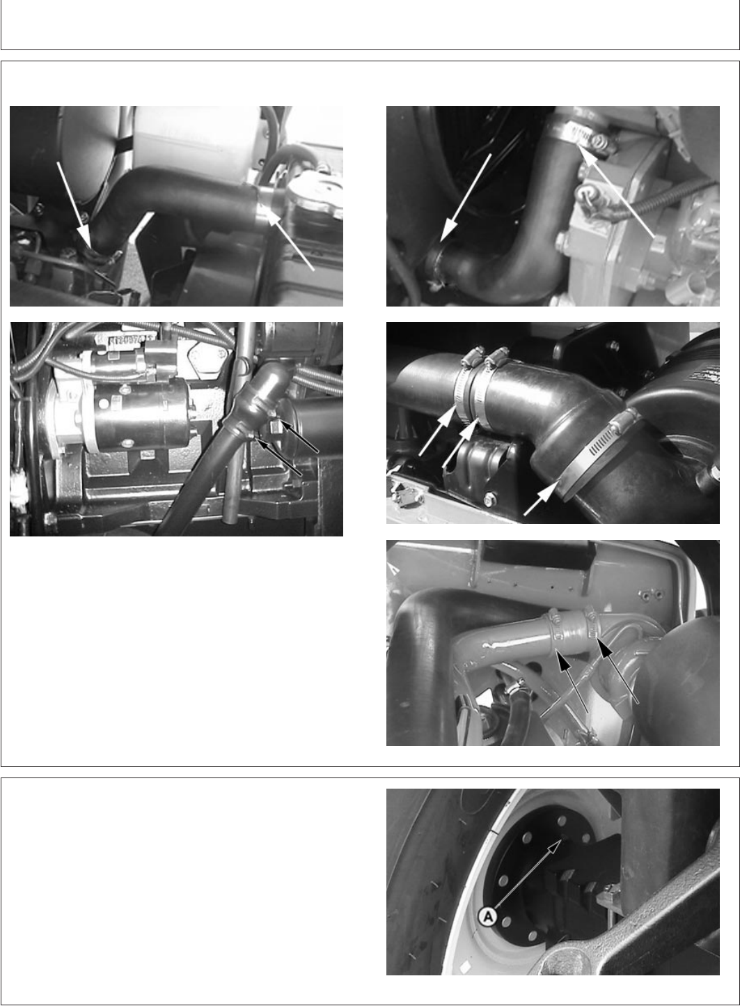
Service—Every 600 Hours
PY80265,05I0227 –19–12SEP05–1/1
Check Hoses and Hose Clamps for Tightness
PY4290 –UN–23FEB06
PY4291 –UN–23FEB06
PY1705 –UN–04NOV03
PY4293 –UN–23FEB06PY4292 –UN–06DEC04
Check the following systems hose clamps for tightness:
•Air Cleaner to engine intake or turbocharger
•Engine Cooling
•Hydraulics
•Fuel
Check all hoses for cracks which could cause leaks or
possible failure. Replace as necessary.
PY80265,05I0228 –19–12SEP05–1/1
Lubricate Rear Axle Bearings
PY4025 –UN–16JUL04
A—Rear Axle Fitting (2 used)
Lubricate rear axle fittings (A), both sides, with several
shots of multi-purpose grease. (See Fuels, Lubricants and
Coolant section.)
115-2
082206
PN=110
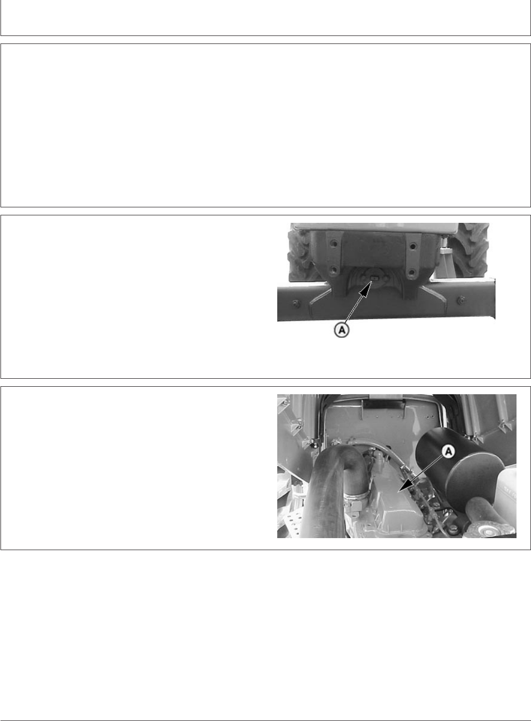
Service—Every 600 Hours
GENERIC,0000060 –19–22FEB06–1/1
Check Engine Idle Speeds
Slow idle speed is 800-875 RPM.
With no load, fast idle speed should be a maximum of
2650 rpm.
If idle speeds are not correct, see your John Deere
dealer.
Specification
Engine—Slow Idle—Speed 800-875 RPM...........................................
Engine—Fast Idle (with No
Load)—Speed 2575-2650 RPM...........................................................
GENERIC,000005F –19–22FEB06–1/1
Check Front Axle Pivot Pin
PY4067 –UN–27JAN05
Front axle
A—Front Axle Pivot Pin
Ask your John Deere dealer to check the front axle pivot
pin (A) for correct end play.
GENERIC,0000061 –19–22FEB06–1/1
Adjust Engine Valve Clearance
PY5509 –UN–16FEB06
Ask your John Deere dealer to make engine valve
clearance adjustment and inspect fuel injectors.
115-3
082206
PN=111
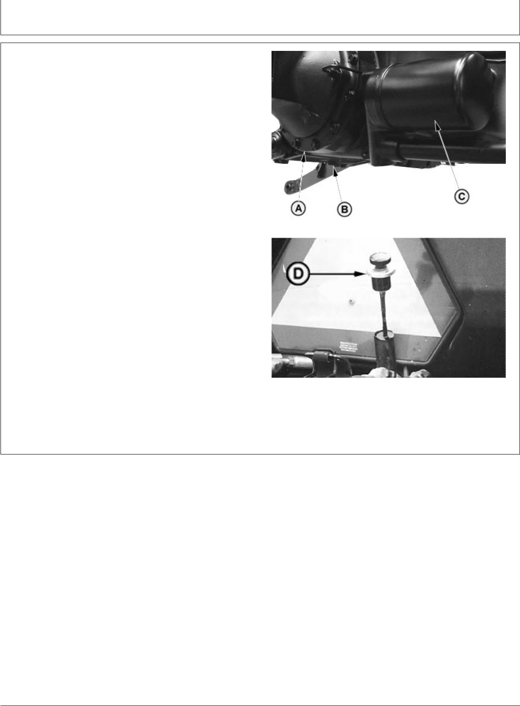
Service—Every 1250 Hours
PY80265,05I0232 –19–12SEP05–1/1
Change Transmission-Hydraulic Oil and
Filter
PY4039 –UN–17JUL04PY4019 –UN–15JUL04
A—Transmission Case
B—Drain Plug
C—Filter
D—Dipstick
1. Lower rockshaft to remove trapped oil.
2. Remove drain plug (B) from transmission case (A) and
drain oil. Dispose of waste oil properly.
3. Replace filter (C) while changing oil. Apply a film of oil
to new filter gasket and install new filter. Hand tighten
only.
4. Fill system with transmission-hydraulic oil. (See Fuels,
Lubricants and Coolant section.)
Specification
Transmission Oil—Capacity 38 L...............................................................
5. Check oil level by means of dipstick. Make sure oil
level is to full level mark. Check again after operating
for five minutes. Add oil if necessary.
120-1
082206
PN=112
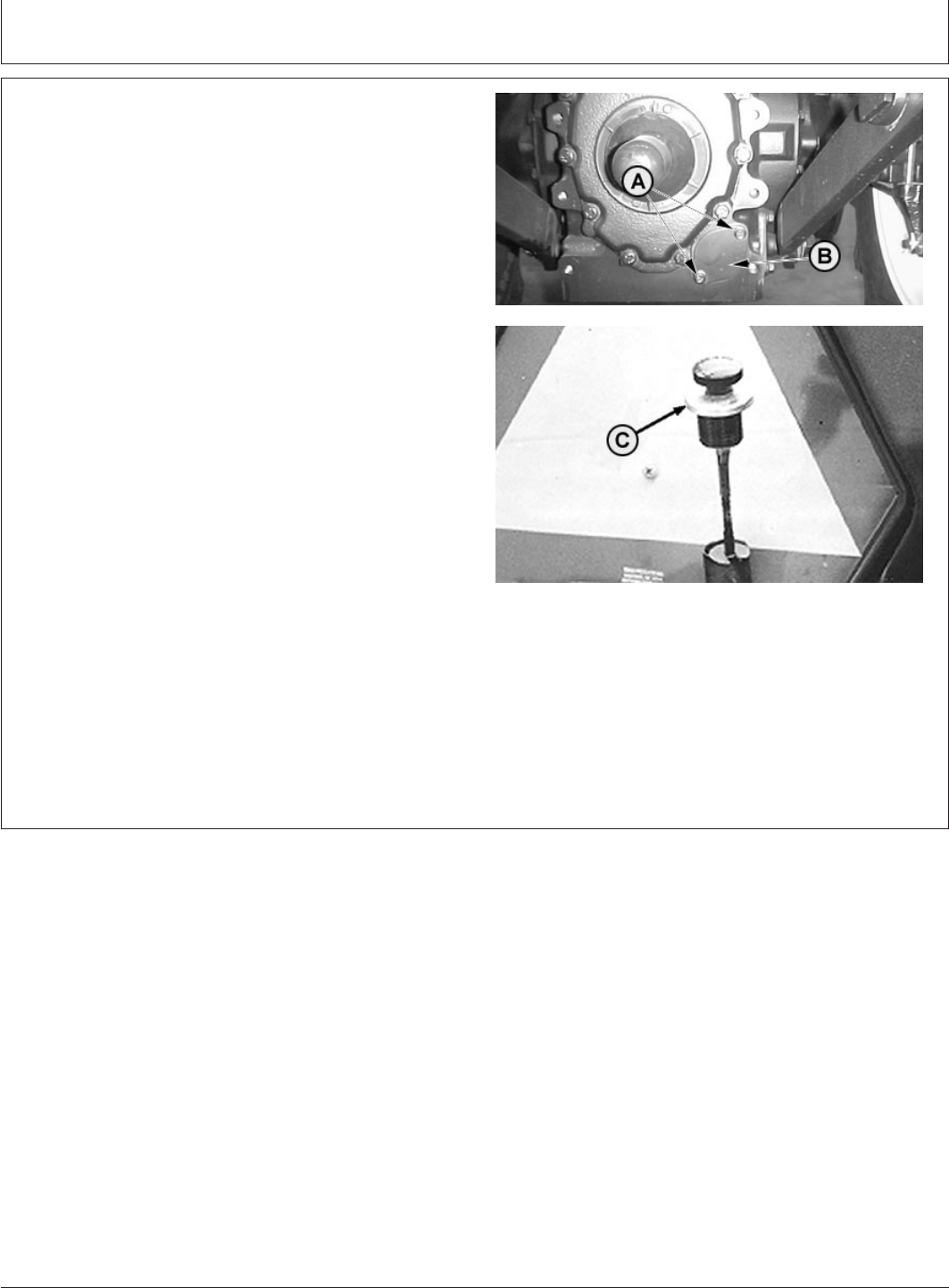
Service—Every 1250 Hours
PY80265,05I0233 –19–11JUL06–1/1
Clean Transmission-Hydraulic Pickup Screen
PY2250 –UN–16MAR04PY2251 –UN–16MAR04
A—Cap Screws (2 used)
B—Screen Cover
C—Dipstick
Remove two cap screws (A) and remove screen cover
(B).
1. Drain transmission-hydraulic oil. (See Change
Transmission-Hydraulic Oil and Filter in this section.)
2. Remove two cap screws (A) and remove screen.
Examine screen for damage. Replace if necessary.
Clean screen in solvent and blow dry with compressed
air.
3. Carefully install screen so the front of screen is
inserted in hole at front of differential case.
4. Fill system with transmission-hydraulic oil. (See
Changing Transmission-Hydraulic Oil and Filter in this
section.)
5. Check oil level at dipstick (C) after filling and again
after operating for 5 minutes.
120-2
082206
PN=113
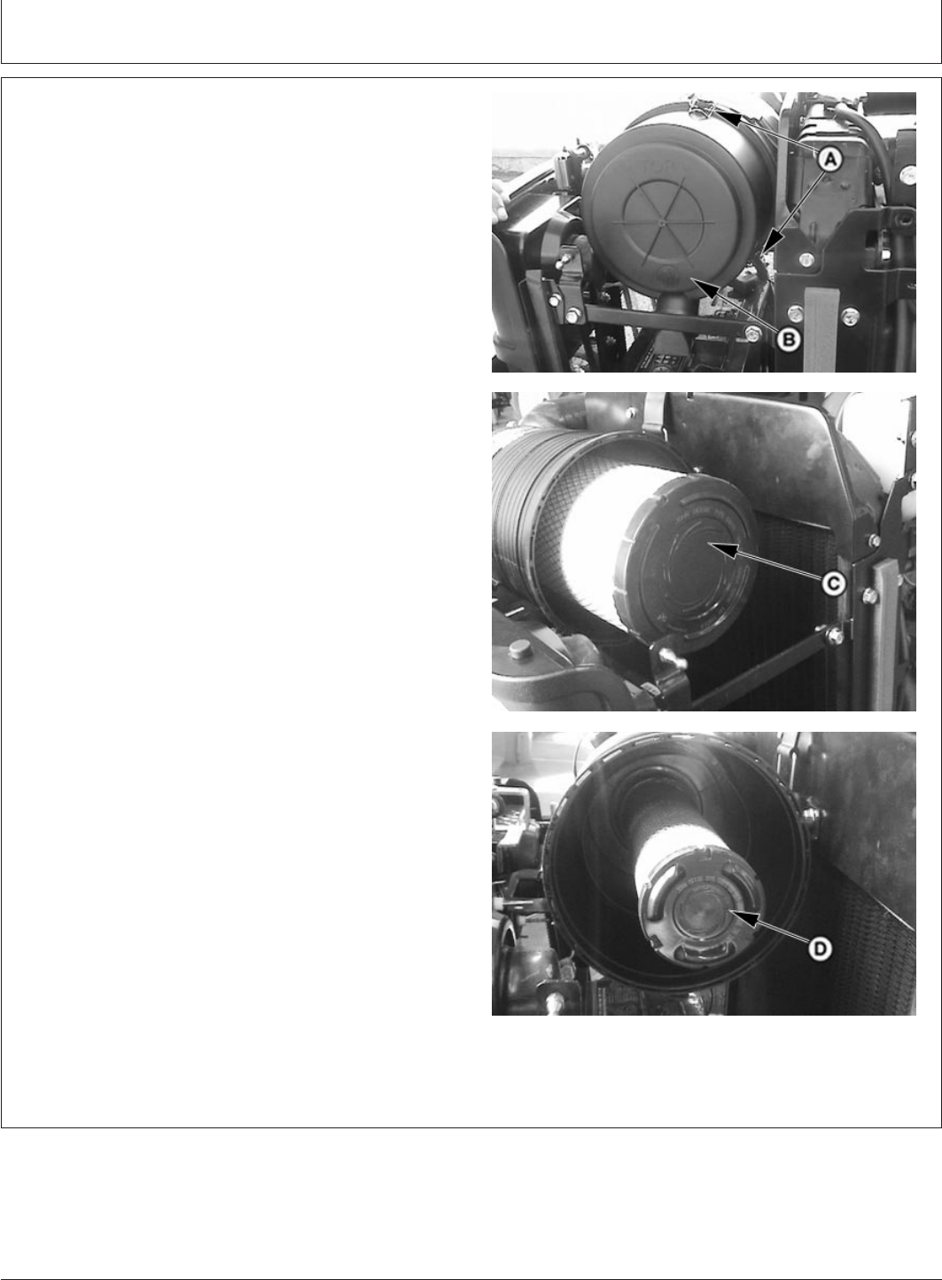
Service—Annually
v34 –19–12SEP05–1/1
Replace Air Cleaner Elements
PY4295 –UN–06DEC04PY4271 –UN–06DEC04PY4294 –UN–06DEC04
A—Clips
B—Cover
C—Primary Element
D—Secondary Element
1. Open hood and remove side screen. (See Removing
Side Screen in Service chapter.)
2. Release clips (A).
3. Remove cover (B).
4. Remove primary element (C).
5. Clean out any dirt in canister taking care not to
damage the secondary filter element.
IMPORTANT: Remove secondary element (inner
element) ONLY if it is to be replaced.
DO NOT attempt to clean secondary
element.
If secondary element is replaced, install
new element immediately to prevent
dust from entering air intake system.
6. Removal of the secondary element (D) is similar to
removal of the primary element.
NOTE: When installing the air cleaner canister, make
sure that the dust unloader valve is facing down.
7. Install secondary element, primary element and cover.
8. Install side screens and close hood.
125-1
082206
PN=114
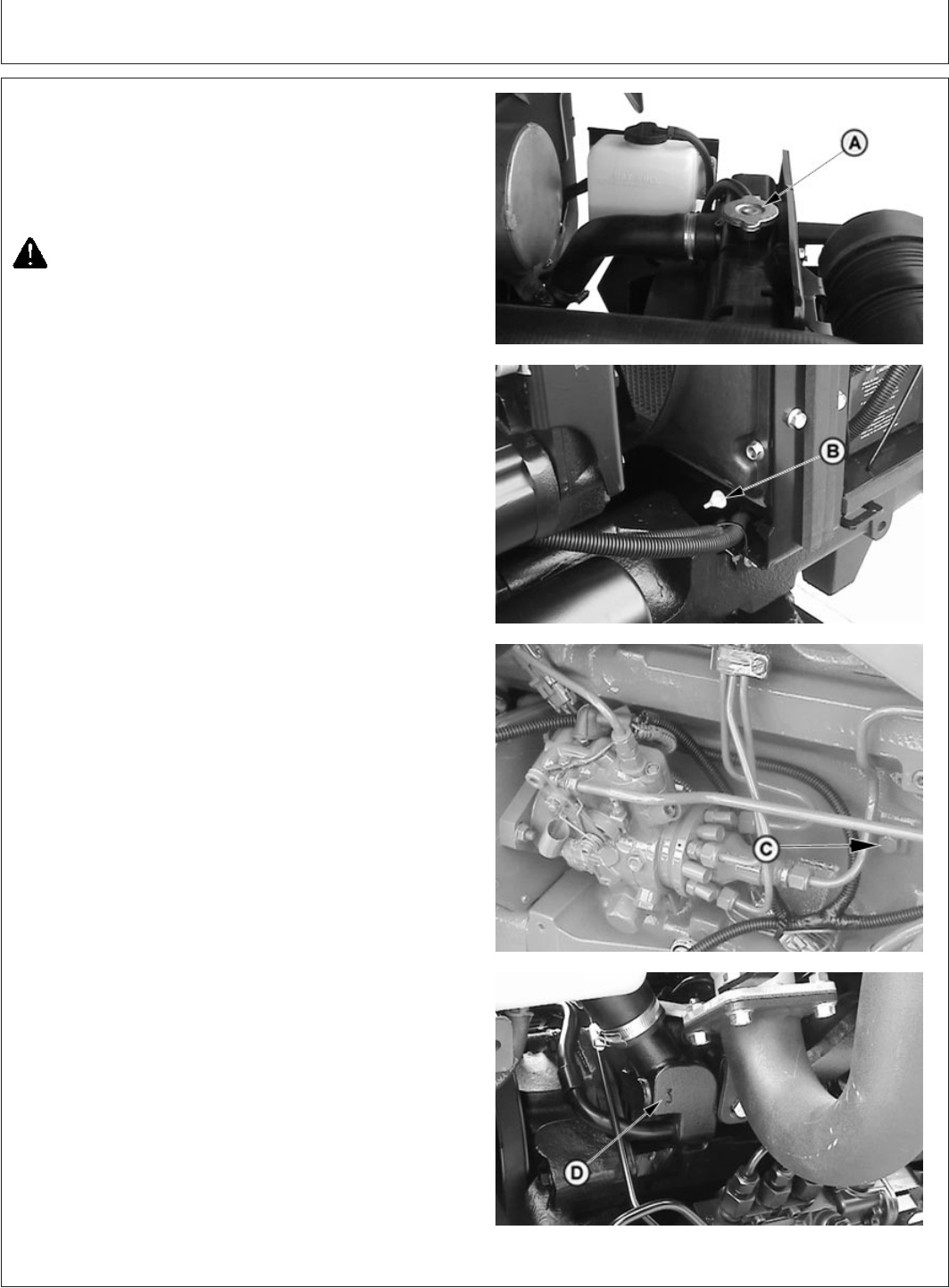
Service—2 Years/2000 Hours
PY80265,05I0235 –19–12SEP05–1/2
Flush Cooling System
PY4157 –UN–28AUG04PY4158 –UN–28AUG04PY5103 –UN–15JUN05PY4159 –UN–28AUG04
A—Radiator Cap
B—Drain Valve
C—Coolant Drain Plug
D—Thermostat Cover
For efficient operation, drain old coolant, flush the entire
system, and fill with clean antifreeze solution at least once
every two years.
CAUTION: DO NOT remove radiator cap or drain
coolant until coolant is cold (temperature gauge
should be below the green striped zone).
Always loosen radiator cap slowly to relieve
any excess pressure.
1. Drain coolant - Remove radiator cap (A). Open drain
valve (B) on radiator and drain coolant from radiator.
Drain coolant from engine block:
IMPORTANT: Thermostat must be removed to ensure
a thorough flush.
2. Remove thermostat cover (D), remove thermostat, and
install cover (without thermostat). Tighten cap screws
to specification.
Specification
Thermostat Cover Cap Screws—
Torque 47 N•.m (35 lb-ft)............................................................................
3. Flush system with water - Close all drain valves/plugs
and fill system with clean water. Run engine about 10
minutes to stir up possible rust or sediment. Stop
engine and drain water from system before rust and
sediment settle.
4. Flush system with radiator cleaner - Close all drain
valve/plugs and fill the cooling system with a good
commercial radiator cleaner and water. Follow
instructions provided with cleaner. Stop engine and
immediately drain system.
5. Flush system with water - Close all drain valves/plugs
and fill with clean water to flush the system. Run the
engine about 10 minutes, then drain out flushing water.
130-1
082206
PN=115
Continued on next page

Service—2 Years/2000 Hours
PY80265,05I0235 –19–12SEP05–2/2
6. Remove thermostat cover and clean off the gasket
material. Apply gasket sealant to new gasket and
install thermostat and cover. Tighten cap screws to
specification.
Specification
Thermostat Cover Cap Screws—
Torque 47 N•.m (35 lb-ft)............................................................................
7. Fill with fresh coolant - Close all drain valves/plugs and
fill with a mixture of antifreeze, soft water, and coolant
conditioner as specified in the Fuels, Lubricants, and
Coolant section.
8. Check coolant level - Fill radiator to the top of the filler
neck. Run the engine until operating temperature is
reached. Let the engine cool (preferably overnight) and
recheck the coolant level. Coolant level with a cold
engine should be at the bottom of the filler neck. When
filling the cooling system it may require several
operating/cooling periods to stabilize the coolant level
in the system. Add make-up coolant to the radiator as
needed to bring the coolant level to the correct level.
130-2
082206
PN=116
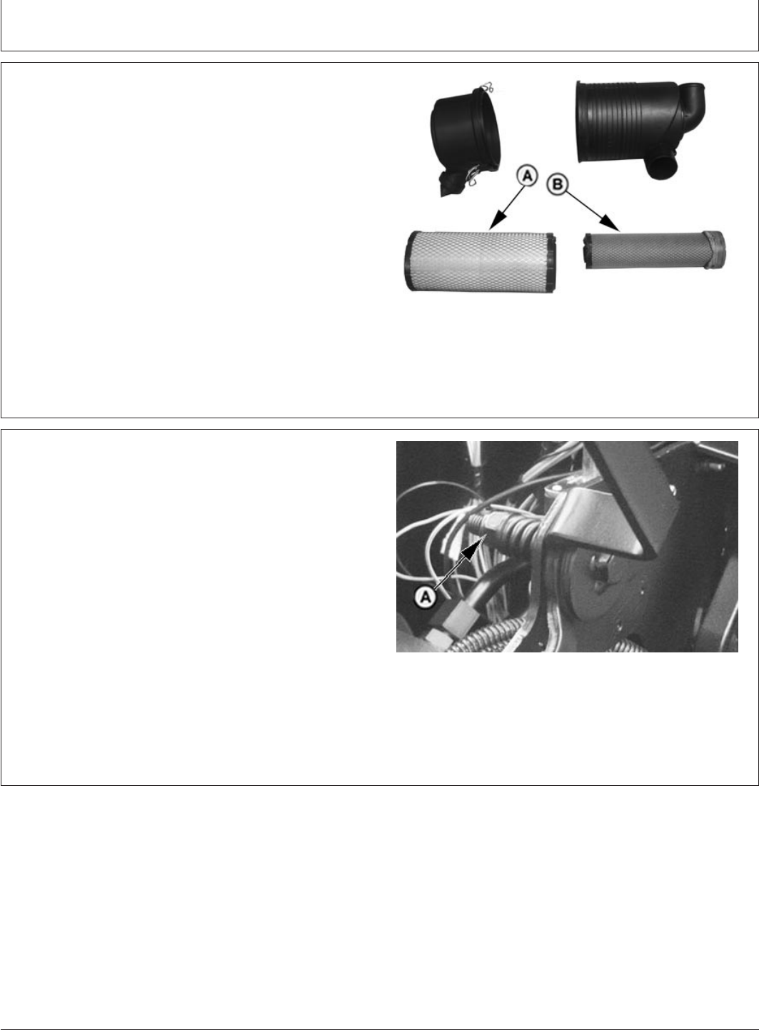
Service—As Required
PY80265,05I0236 –19–28JUN06–1/1
Service Air Cleaner
PY5790 –UN–08JUN06
A—Primary Element
B—Secondary Element
Under dusty conditions, it may be necessary to service air
cleaner more often than every 250 hours. Whenever dirty
primary element is indicated by loss of power, excessive
smoke or air restriction indicator light, replace primary
element (A). (See Replace Air Cleaner in Service—250
Hours section.)
PY80265,05I0237 –19–12SEP05–1/1
Adjust Throttle Friction
PY4072 –UN–24JAN05
A—Throttle Lever Lock Nut
When throttle linkage becomes loose and does not stay in
set position, adjust as follows:
NOTE: Instrument and side panels removed for
illustration purposes. Throttle lever lock nut can be
accessed by lowering key switch cover.
1. Adjust spring tension by loosening or tightening lock
nut (A) until throttle lever movement is smooth
throughout range of travel with only slight drag.
135-1
082206
PN=117

Service
PY80265,05I0238 –19–12SEP05–1/1
Additional Service Information
This is not a detailed service manual. It contains only
information needed for operation and routine
maintenance. If you want more detailed service
information, refer to Parts Catalog and/or a Technical
Manual available at Dealership
GENERIC,0000062 –19–22FEB06–1/1
Service Tractor Safely
Disengage power to attachments and stop engine
before making any repairs or adjustments.
Do not change engine governor setting or overspeed
engine.
Keep the vehicle and attachments in good operating
condition.
Keep safety devices in place and in working condition.
Keep all nuts, bolts, and screws tight to be sure the
equipment is in safe working condition.
Before you work on any part of the engine, stop the
engine, and let it cool. Hot engine parts can burn skin
on contact.
Never run engine unless range shift lever is in neutral
position.
Be careful to prevent clothing, jewelry, or long hair
from getting caught in the fan blades, drive belts, or
any other moving engine parts.
Unauthorized modifications to the machine may impair
the function and/or safety and affect machine life.
PY80265,05I0240 –19–12SEP05–1/1
Engine Break-In Oil
New engines are filled at the factory with John Deere
ENGINE BREAK-IN OIL. During the break-in period,
add John Deere ENGINE BREAK-IN OIL as needed to
maintain the specified oil level. Change the oil and
filter after the first 100 hours of operation of a new or
rebuilt engine.
140-1
082206
PN=118
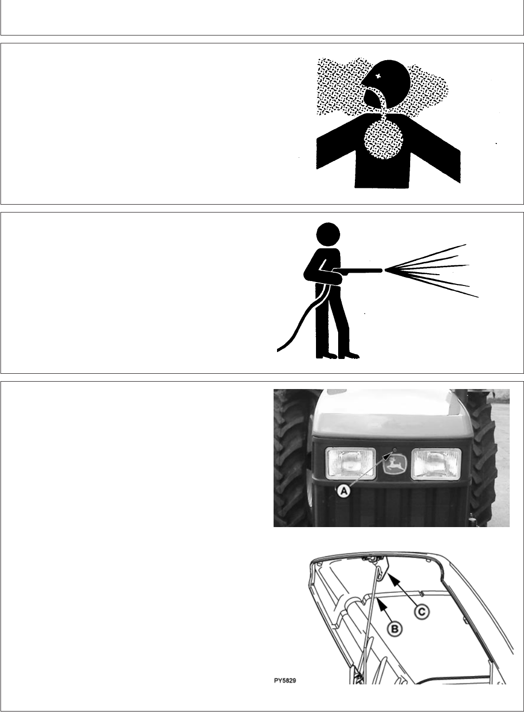
Service
PY80265,05I0241 –19–12SEP05–1/1
Work In Ventilated Area
TS220 –UN–23AUG88
Engine exhaust fumes can cause sickness or death. If it is
necessary to run an engine in an enclosed area, remove
the exhaust fumes from the area with an exhaust pipe
extension.
If you do not have an exhaust pipe extension, open the
doors and get outside air into the area
PY80265,05I0242 –19–12SEP05–1/1
Using High-Pressure Washers
T6642EJ –UN–18OCT88
IMPORTANT: Directing pressurized water at
electronic/electrical components or
connectors, bearings and hydraulic
seals, fuel injection pumps or other
sensitive parts and components may
cause product malfunctions. Reduce
pressure, and spray at a 45 to 90
degree angle.
PY80265,05I0243 –19–28JUN06–1/1
Opening Hood
PY5152 –UN–21AUG05
PY5829 –UN–20JUN06
A—Hood Latch Release
B—Hood Support Rod
C—Hood Latch Striker
1. Push hood latch release (A) in to unlock hood.
2. Raise hood and lift the support rod (B).
3. Insert the hood support rod into the hood latch striker
slot (C) to hold hood in raised position.
140-2
082206
PN=119
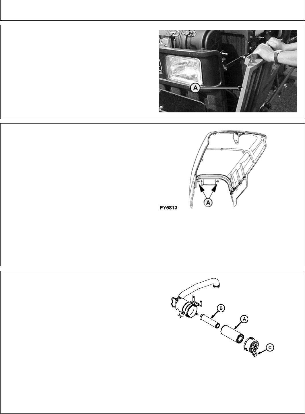
Service
PY80265,05I0244 –19–12SEP05–1/1
Removing Side Screens
PY1736 –UN–14DEC05
A—Side Screens
1. Raise the hood and secure with the support rod.
2. Pull side screen (A).
3. Tilt screen outward and lift from lower mounting slots.
PY80265,05I0245 –19–28JUN06–1/1
Removing Hood
PY5813 –UN–19JUN06
A—Cap Screws (2 used)
1. Remove side screens. (See Removing Side Screens in
this chapter.)
2. Remove two cap screws (A) securing hood.
3. Release the hood support rod from the hood latch and
secure the rod in the stored position.
4. Remove hood from tractor.
PY80265,05I0246 –19–12SEP05–1/1
Air Intake System Components
LV4089 –UN–20JUL99
8’ Air cleaner
A—Primary Air Cleaner Element
B—Secondary Air Cleaner Element
C—Dust Unloader Valve
Air enters the intake system through the open end of the
air cleaner canister. A major portion of the dust is
separated out by air turbulence action of the primary air
cleaner element (A) and passed out into the radiator inlet
air flow through the dust unloader valve (C). If the primary
element becomes plugged, dust is filtered out by the
secondary element (B).
140-3
082206
PN=120
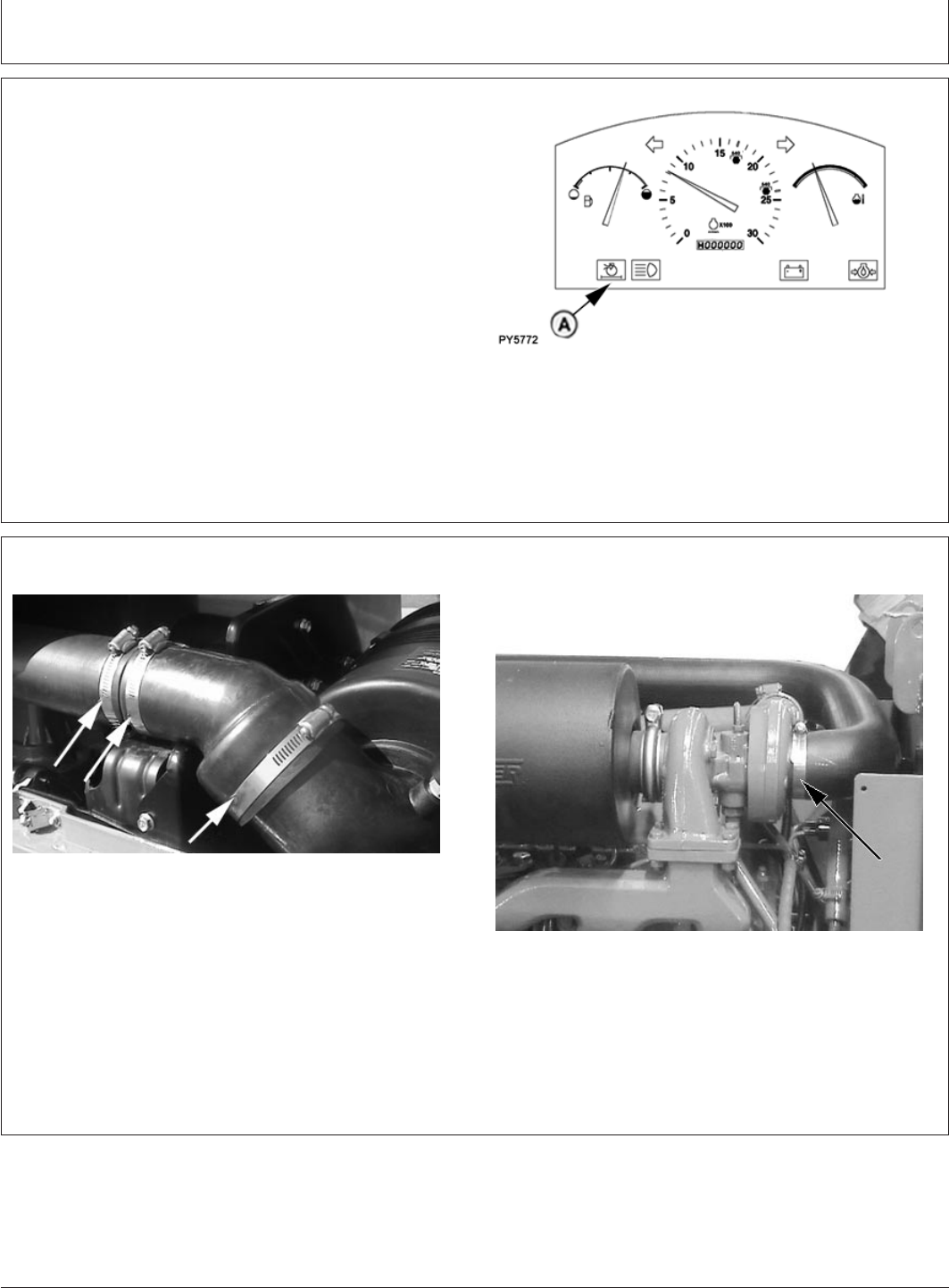
Service
PY80265,05I0247 –19–02JUN06–1/1
Service Air Cleaner at Regular Intervals
PY5772 –UN–02JUN06
A—Air Restriction Indicator
Service air cleaner if air restriction indicator (A) illuminates
or at least every 250 hours. Replace air cleaner elements
at least once a year.
The smaller “secondary” element should be removed only
when being replaced, normally once a year. (See Replace
Air Cleaner in Service—250 Hours section.)
PY80265,05I0248 –19–12SEP05–1/1
Checking Air Intake System
PY4293 –UN–23FEB06
PY4361 –UN–29DEC04
Check all air intake system clamps for tightness.
140-4
082206
PN=121
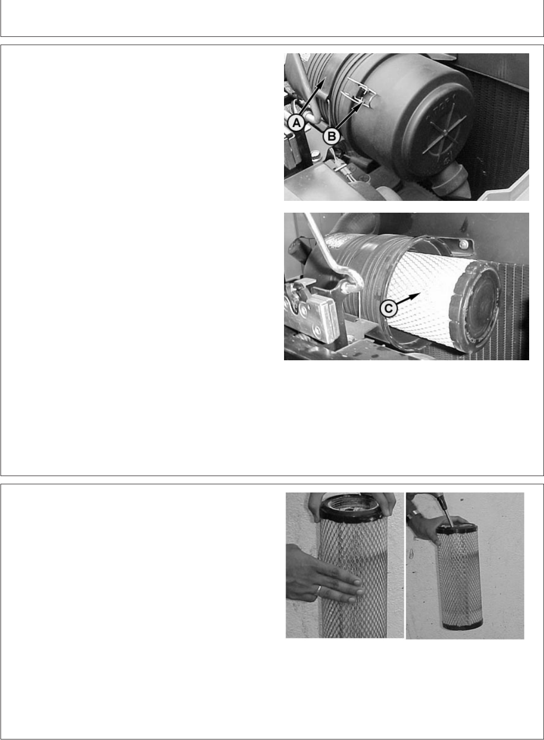
Service
PY80265,05I0249 –19–11JUL06–1/1
Removing Primary Air Cleaner Element
PY1100 –UN–29JUL01PY1113 –UN–29JUL01
A—Rubber Strap
B—Clip
C—Primary Element
1. Disconnect rubber strap (A) at the front of the canister.
2. Lift clip (B) and pull canister cover.
3. Clean out any dirt in canister taking care not to
damage the secondary filter element.
4. Removal of the secondary element is similar to
removal of the primary element.
IMPORTANT: Remove secondary element (inner
element) ONLY if it is to be replaced.
DO NOT attempt to clean secondary
element. If secondary element is
replaced, install new element
immediately to prevent dust from
entering air intake system. When
replacing the air cleaner canister, make
sure that the dust cup/ejector hose is
facing downward.
PY80265,05I0250 –19–12SEP05–1/1
Cleaning Primary Element
PY1114 –UN–29JUL01
1. Pat sides of element gently to loosen dirt. DO NOT tap
element against a hard surface.
2. clean element with compressed air (below 690 kPa or
100 psi). Hold nozzle next to inner surface, and move
up and down pleats.
IMPORTANT: DO NOT direct air against outside of
element, as it might force dirt through
to inside.
3. Inspect element before reinstalling.
140-5
082206
PN=122
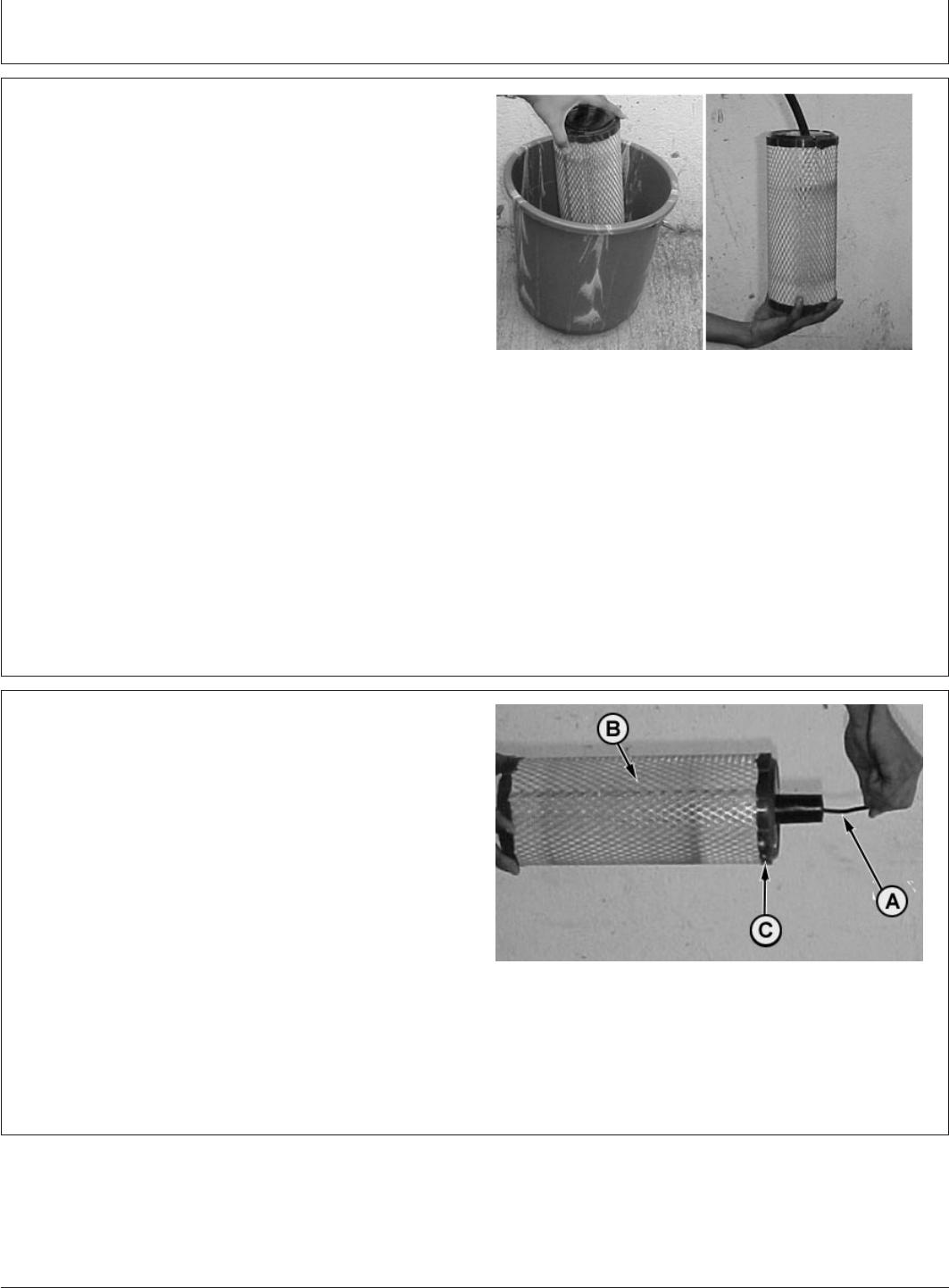
Service
PY80265,05I0251 –19–12SEP05–1/1
Washing Primary Element
PY1122 –UN–31JUL01
IMPORTANT: Never wash element in gasoline or any
solvent. Never use compressed air on a
wet element. Do not oil element.
1. If element is coated with oil or soot, wash in a solution
of warm water . Let element soak at least 15 minutes,
then agitate gently to flush out dirt.
2. Rinse element thoroughly from inside with clean water.
Use element cleaning gun or a free-running hose.
Keep water pressure low (below 280 kPa or 40 psi) to
avoid damaging element.
3. Allow element to dry completely before using. This
usually takes from one to three days. DO NOT oven
dry or use drying agents. Protect element from freezing
until dry.
4. Inspect element before installing.
PY80265,05I0252 –19–12SEP05–1/1
Inspecting Element
PY1636 –UN–30SEP03
A—Light Source
B—Element
C—Rubber Sealing Surface
1. Hold a bright light (A) inside element (B) and check
carefully for holes. Discard any element which shows
the slightest hole.
2. Be sure outer screen is not dented. Vibration would
quickly wear a hole in filter.
3. Be sure rubber sealing surfaces (C) are in good
condition on both ends. If damaged, replace element.
140-6
082206
PN=123
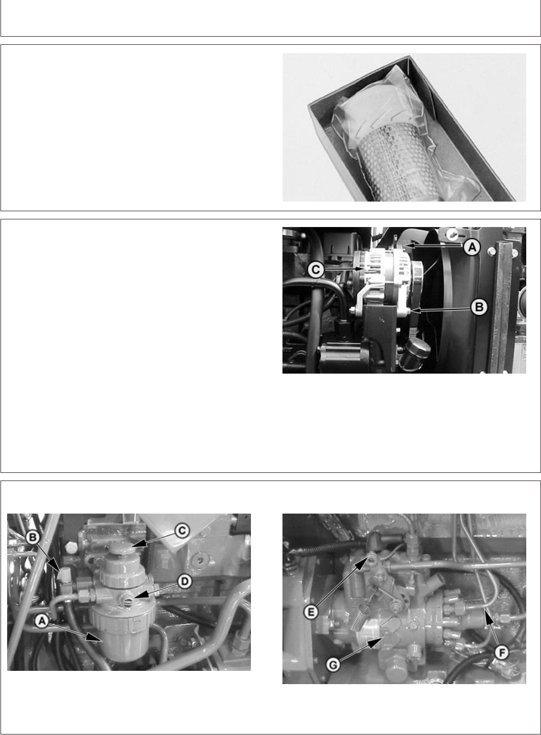
Service
PY80265,05I0253 –19–12SEP05–1/1
Storing Element
RW471 –UN–26FEB90
If element is not installed on tractor, seal element in a
plastic bag and store in its original shipping container to
protect against dust and damage.
PY80265,05I0254 –19–12SEP05–1/1
Replacing Alternator/Fan Belt
PY1652 –UN–27OCT03
A—Alternator Cap Screw
B—Alternator Bolt
C—Alternator
1. Loosen cap screw (A) and bolt (B) and rotate the
alternator (C) to free the belt.
2. Remove belt from drive pulley.
3. Belt can be pulled around fan to remove.
4. Install new belt in reverse order of removal.
5. Adjust belt tension. (See Inspect and Adjust
Alternator/Fan Belt in Service—250 Hours section.)
GENERIC,0000063 –19–22FEB06–1/1
Fuel System Components
PY4297 –UN–06DEC04
PY4296 –UN–06DEC04
A—FuelGarda
¨fuel filter C—Priming pump E—Electric fuel shut-off G—Injection pump
B—Fuel shut-off valve D—Bleed screw F—Fuel injection lines
140-7
082206
PN=124
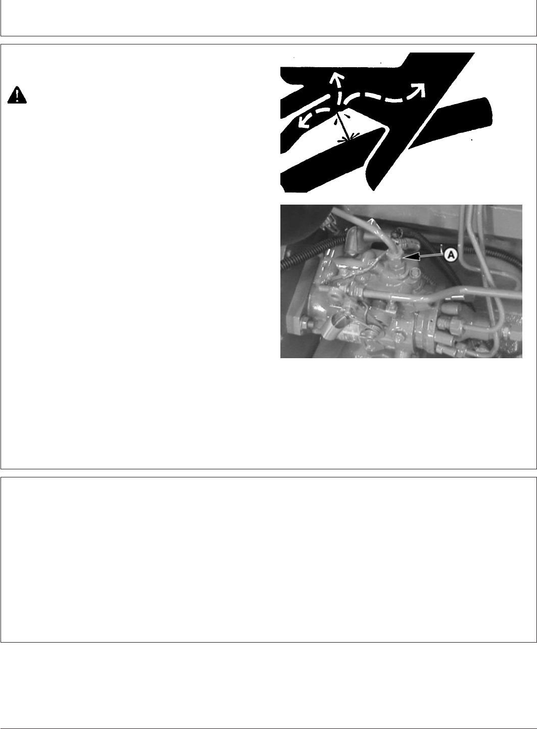
Service
PY80265,05I0256 –19–11JUL06–1/1
Bleeding Fuel System
X9811 –UN–23AUG88
PY4277 –UN–06DEC04
A—Fuel Return Line
CAUTION: Escaping fluid under pressure can
penetrate the skin causing serious injury. Avoid
the hazard by relieving pressure before
disconnecting hydraulic or other lines. Tighten
all connections before applying pressure.
Search for leaks with a piece of cardboard.
Protect hands and body from high pressure
fluids.
If an accident occurs, see a doctor immediately.
Any fluid injected into the skin must be
surgically removed within a few hours or
gangrene may result. Doctors unfamiliar with
this type of injury should reference a
knowledgeable medical source. Such
information is available from Deere & Company
Medical Department in Moline, Illinois, U.S.A.
1. Fuel tank must be full of fuel with the fuel shut-off
valve open.
IMPORTANT: To avoid injection pump damage, DO
NOT attempt to start the engine while
bleeding the fuel system.
2. Loosen fuel return line (A).
PY80265,05I0257 –19–17FEB06–1/1
Do Not Modify Fuel System
IMPORTANT: Modification or alteration of the
injection pump, the injection pump
timing, or the fuel injectors in ways
not recommended by the
manufacturer will terminate the
warranty obligation to the purchaser.
(See warranty information inside
front cover.)
DO NOT attempt to service injection
pump or fuel injectors yourself.
Special training and special tools are
required. (See your John Deere
dealer.)
140-8
082206
PN=125
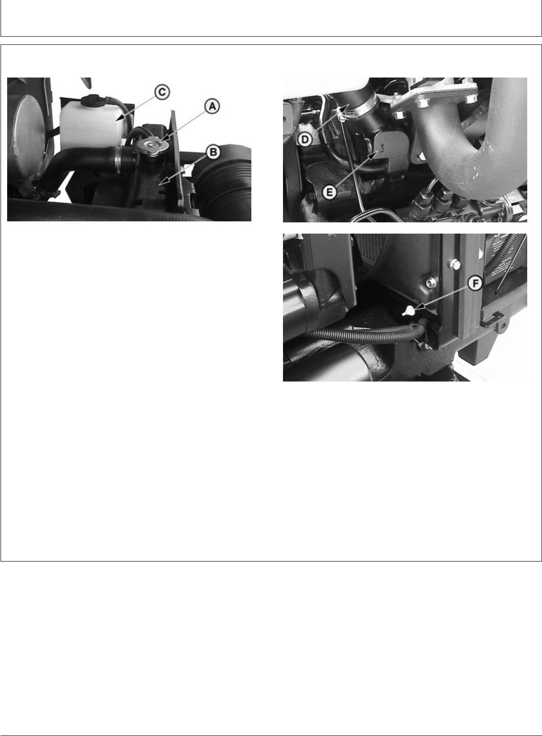
Service
PY80265,05I0258 –19–11JUL06–1/1
Engine Cooling System Components
PY4161 –UN–28AUG04
PY4163 –UN–28AUG04PY4162 –UN–28AUG04
A—Radiator Cap
B—Radiator
C—Coolant Recovery Tank
D—Upper Radiator Hose
E—Thermostat Housing
F—Radiator Drain
IMPORTANT: Never pour cold water into the cooling
system of a hot engine, as it might
crack cylinder block or head. DO NOT
operate engine without coolant for even
a few minutes.
The tractors utilize a remote coolant recovery tank.
Make-up coolant is added to the coolant recovery tank
rather than directly to the radiator.
140-9
082206
PN=126
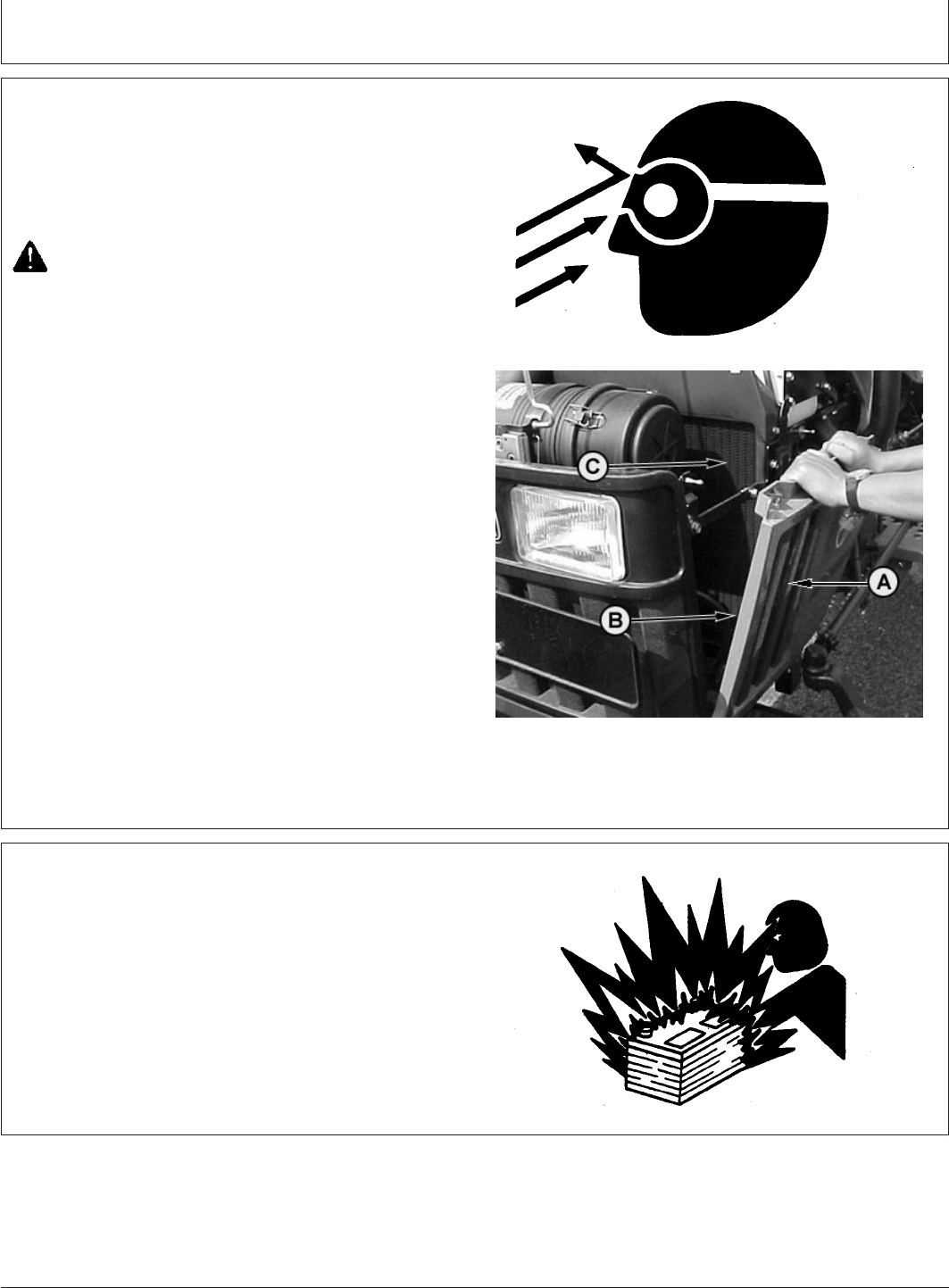
Service
PY80265,05I0259 –19–12JUL06–1/1
Cleaning Grille, Screens, Radiator and Oil
Cooler
TS266 –UN–23AUG88PY1804 –UN–15NOV03
A—Grille
B—Side Screens
C—Radiator
1. Whenever trash builds up on grille (A) or side screens
(B), stop engine and brush clean.
CAUTION: Reduce compressed air to less than
210 kPa (2 bar) (30 psi) when using for cleaning
purposes. Clear area of bystanders, guard
against flying chips, and wear personal
protection equipment including eye protection.
2. Remove side screens (B), and see if trash has built up
on radiator (C). If so, carefully remove it using a brush
or compressed air.
3. If a more thorough cleaning is necessary, clean
radiator from behind with compressed air or water.
Straighten any bent fins.
PY80265,05I0260 –19–12SEP05–1/1
Prevent Battery Explosions
TS204 –UN–23AUG88
Keep sparks, lighted matches, and open flame away from
the top of battery. Battery gas can explode.
Never check battery charge by placing a metal object
across the posts. Use a volt-meter or hydrometer.
Do not charge a frozen battery; it may explode. Warm
battery to 16°C (60°F).
140-10
082206
PN=127
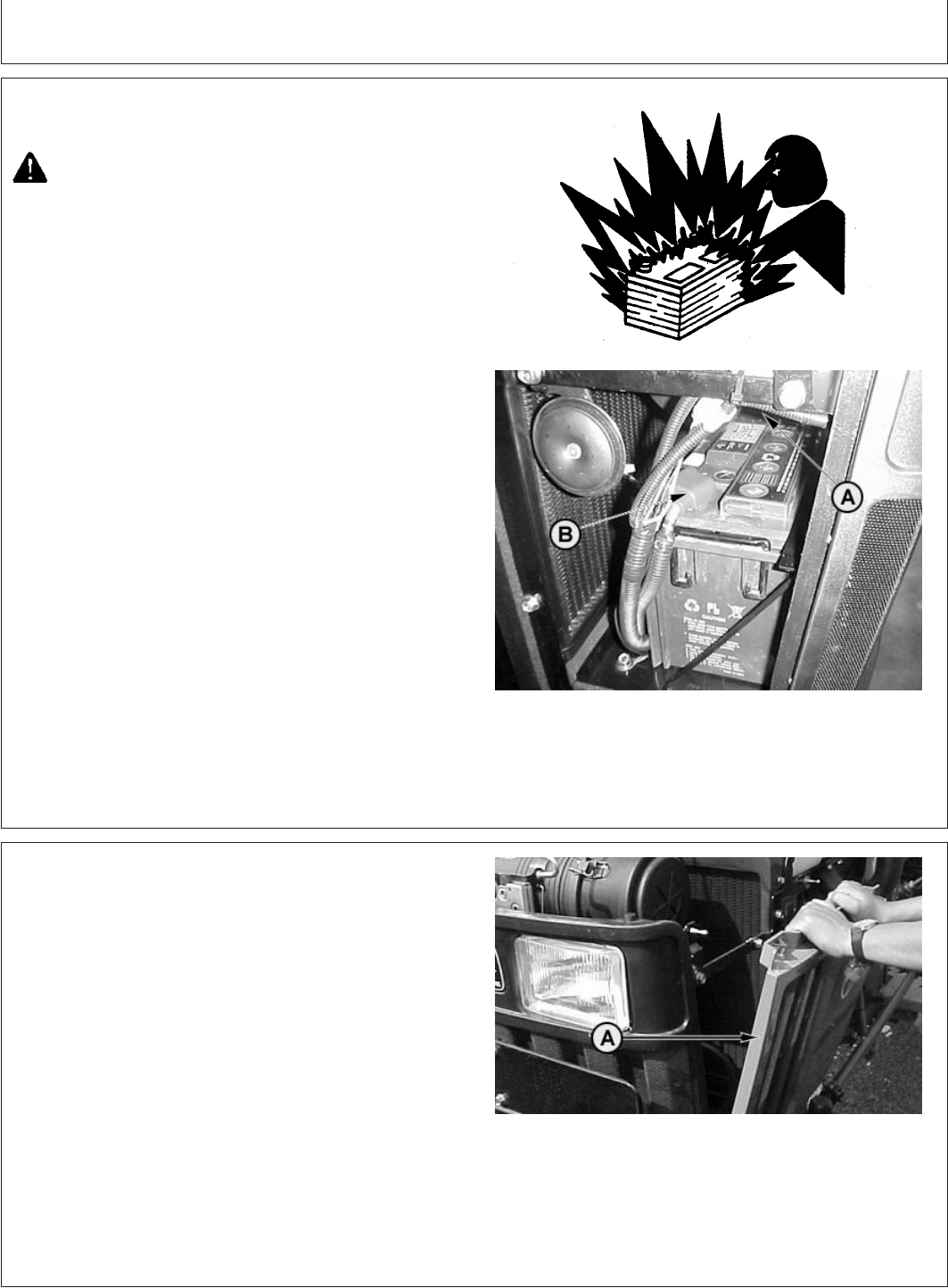
Service
PY80265,05I0261 –19–12SEP05–1/1
Observe Electrical Service Precautions
TS204 –UN–23AUG88PY1968 –UN–24FEB04
A—Positive (+) Battery Cable
B—Negative (—) Battery Cable
CAUTION: Keep all sparks and flames away
from batteries, as gas given off by electrolyte is
explosive. To avoid sparks, connect negative
(ground) cable (B) last and disconnect it first.
When using a booster battery, follow
instructions in “Operating the Engine” section.
To avoid shocks and burns, disconnect battery
negative (ground) cable (B) before servicing any
part of the electrical system, then remove
positive cable (A) if removing battery.
Keep all electrical shields in place.
PY80265,05I0262 –19–12SEP05–1/1
Battery Access
PY1736 –UN–14DEC05
A—Side Screens
Battery is located in front of the radiator.
To gain access:
1. Raise the hood.
2. Pull side screens (A) and remove from slots. (See
Removing Side Screens in this section.)
140-11
082206
PN=128
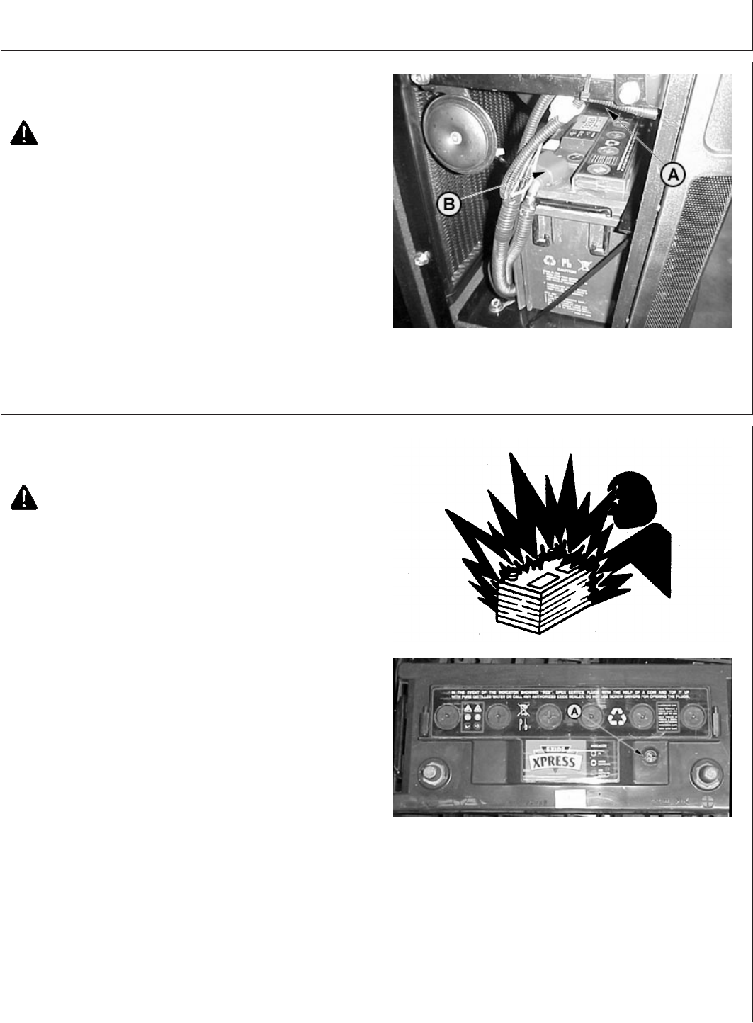
Service
PY80265,05I0263 –19–12SEP05–1/1
Removing Battery
PY1968 –UN–24FEB04
A—Positive (+) Cable Nut
B—Negative (—) Cable Nut
CAUTION: To avoid sparks, disconnect negative
(ground) cable first and connect it last.
1. Remove negative (ground) battery cable (B) and
remove the cable connection. Then remove positive
cable (A) and connection.
Loosen nuts securing battery hold-down and rotate the
holder down, freeing the battery.
2. Lift and slide the battery from the battery tray.
PY80265,05I0264 –19–12SEP05–1/1
Checking Battery Condition
TS204 –UN–23AUG88PY2252 –UN–16MAR04
CAUTION: Battery gas can explode. Keep
sparks and flames away from batteries. Use a
flashlight to check battery electrolyte level.
Never check battery charge by placing a metal
object across the posts. Use a voltmeter or
hydrometer.
Always remove grounded (—) battery clamp
first and replace it last.
In MHD99 battery eye is provided on top face on battery.
The eye shows three different colours, which indicates
condition of battery
1. If eye shows GREEN colour , it means battery is full
chareged.
2. If eye shows WHITE colour, it means charging
required.
3. If eye shows RED colour, it means add distilled water.
140-12
082206
PN=129
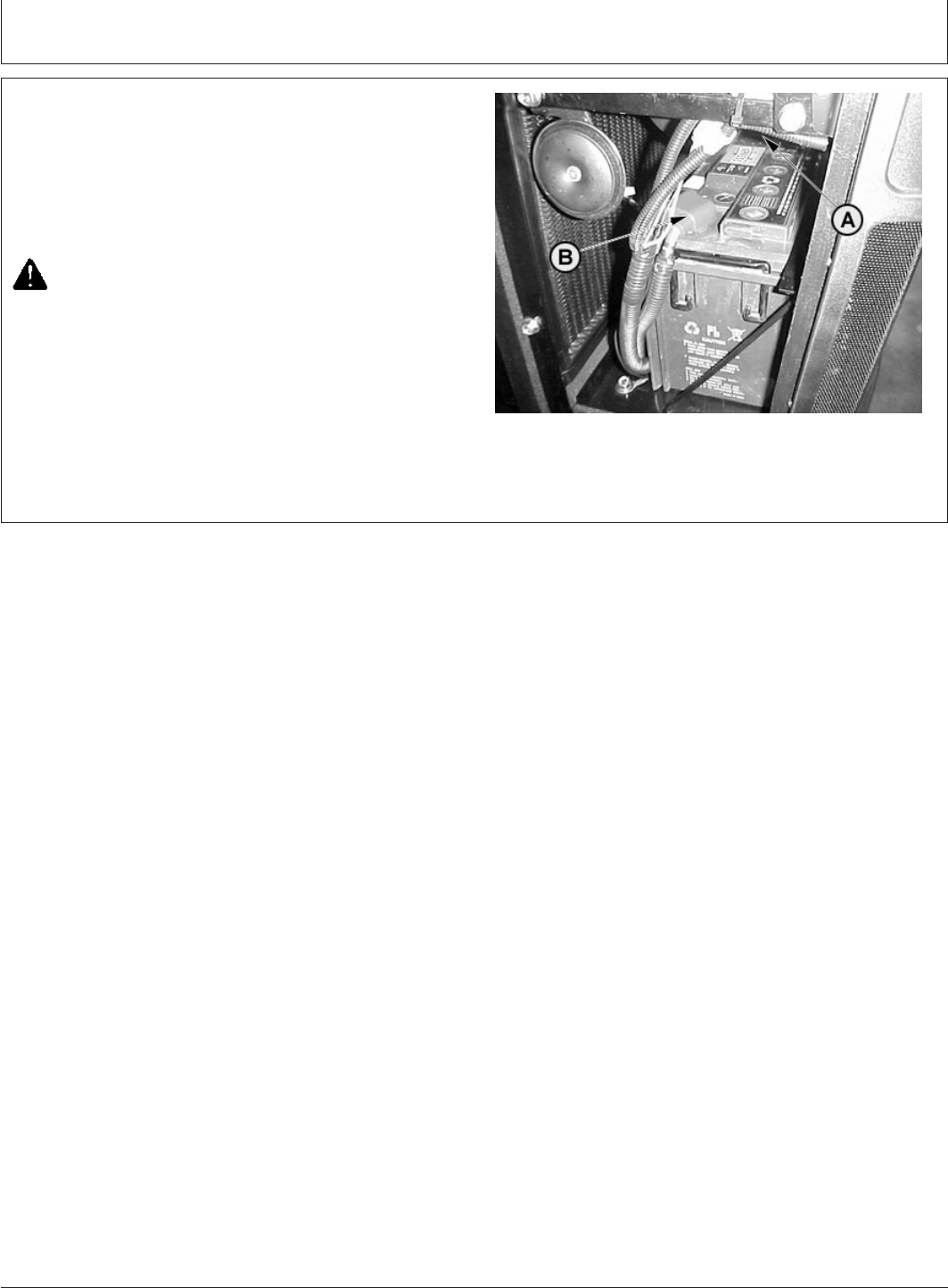
Service
PY80265,05I0265 –19–12SEP05–1/2
Servicing Battery
PY1968 –UN–24FEB04
A—Positive (+) Battery Terminal
B—Negative (—) Battery Terminal
1. Keep battery clean by wiping with a damp cloth. Keep
all connections (A and B) clean and tight. To remove
any corrosion, wash terminals with a solution of four
parts water to one part baking soda.
CAUTION: To avoid sparks, connect negative
(ground) (—) cable last and disconnect it first.
2. Keep battery fully charged, especially during cold
weather. If a battery charger is connected, attach a
positive cable to the positive battery terminal (A).
Connect the negative battery charger lead to a good
ground on tractor frame.
Continued on next page
140-13
082206
PN=130
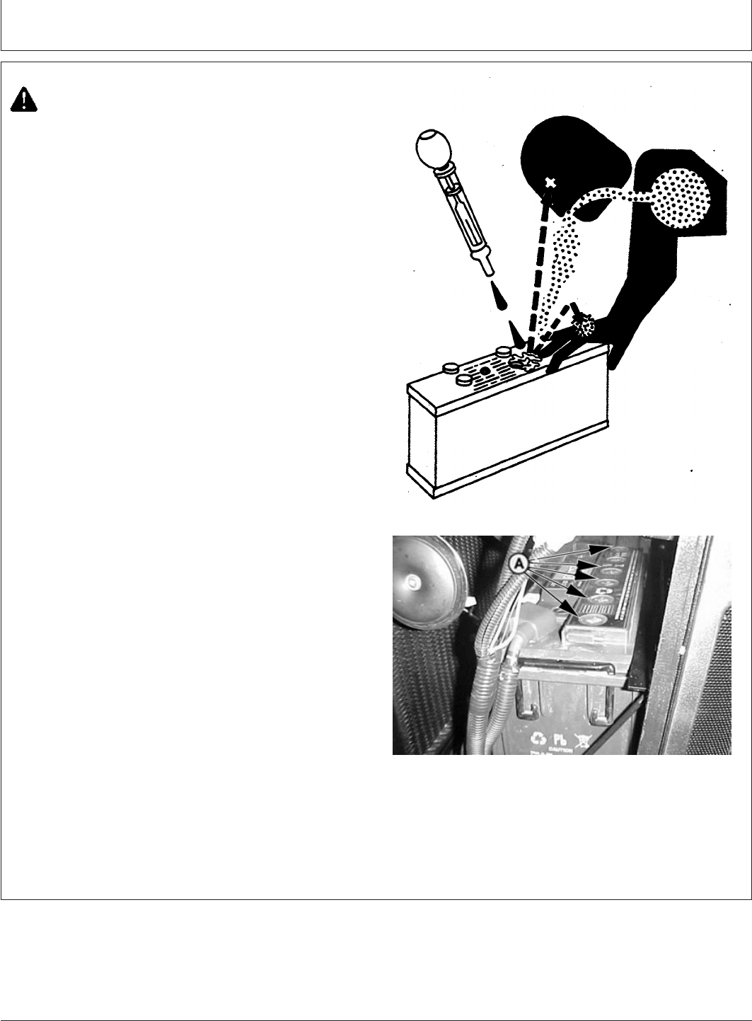
Service
PY80265,05I0265 –19–12SEP05–2/2
TS203 –UN–23AUG88PY4954 –UN–21APR05
A—Battery Cells
CAUTION: Sulfuric acid in battery electrolyte is
poisonous. It is strong enough to burn skin, eat
holes in clothing, and cause blindness if
splashed into eyes.
Avoid the hazard by:
1. Filling batteries in a well-ventilated area.
2. Wearing eye protection and rubber gloves.
3. Avoiding breathing fumes when electrolyte is
added.
4. Avoiding spilling or dripping electrolyte.
5. Use proper jump start procedure.
If you spill acid on yourself:
1. Flush your skin with water.
2. Apply baking soda or lime to help neutralize
the acid.
3. Flush your eyes with water for 15—30
minutes. Get medical attention immediately.
If acid is swallowed:
1. Do not induce vomiting.
2. Drink large amounts of water or milk, but do
not exceed2L(2quarts).
3. Get medical attention immediately.
IMPORTANT: DO NOT add water in freezing weather
unless tractor will be run at least 30
minutes to assure thorough mixing.
3. Check level of electrolyte in each cell (A) at least every
250 hours. If low, fill to bottom of filler necks with
CLEAN, SOFT water. DO NOT OVERFILL.
4. Coat terminals with a small amount of grease.
140-14
082206
PN=131
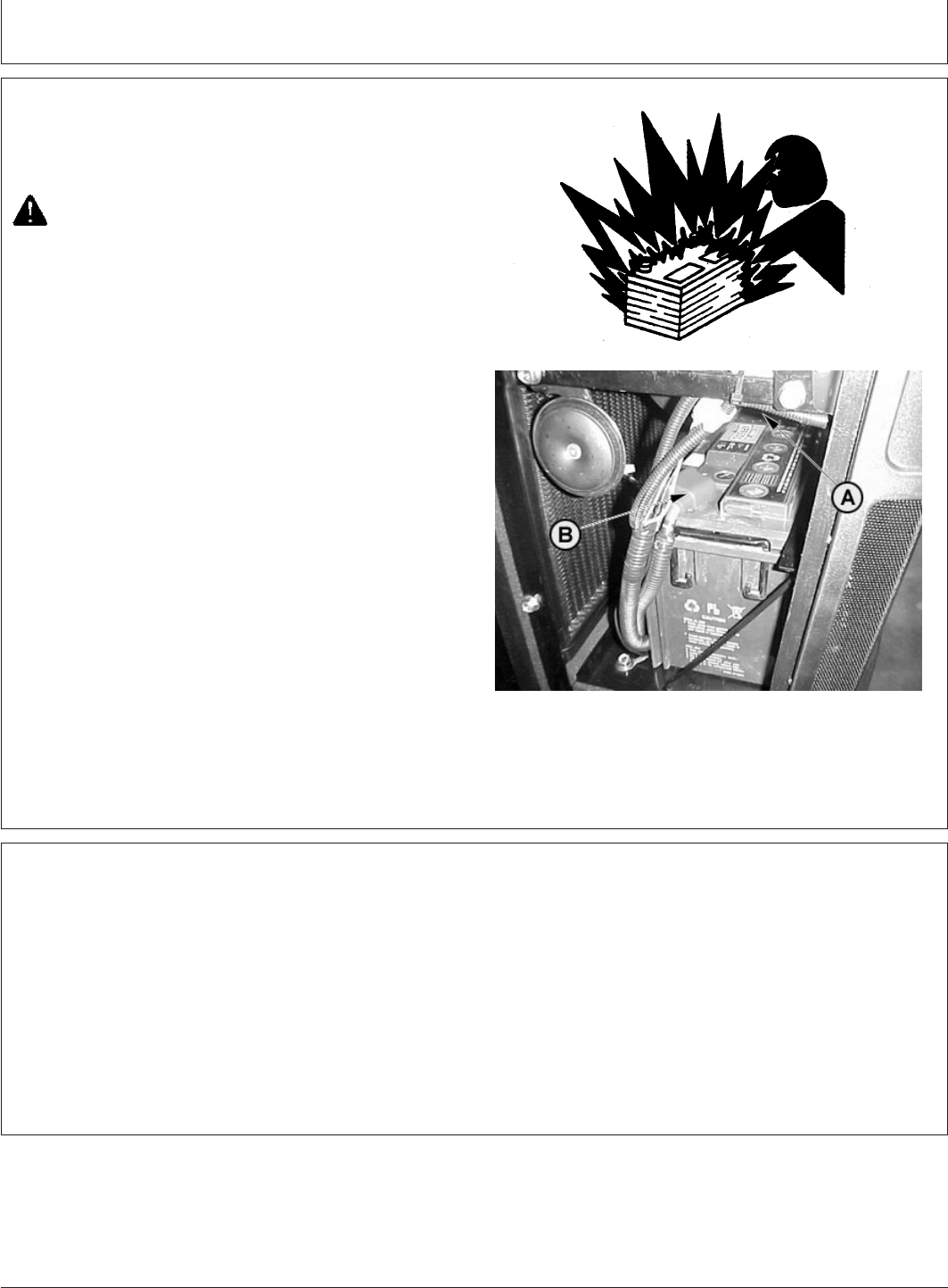
Service
PY80265,05I0266 –19–12SEP05–1/1
Charging Battery
TS204 –UN–23AUG88PY1968 –UN–24FEB04
A—Positive (+) Battery Terminal
B—Negative (—) Battery Terminal
Keep battery fully charged, especially during cold weather.
CAUTION: Gas given off by battery is explosive.
Keep sparks and flames away from battery.
Before connecting or disconnecting a battery
charger, turn charger off. Make last connection
and disconnection at a point away from battery.
1. With charger off, attach positive battery charger lead to
positive (+) battery terminal (A). Attach negative
charger lead to tractor frame away from the battery.
2. Turn charger on and recharge the battery following
battery manufacturer’s instructions for using charger.
Check battery condition as described below.
3. To disconnect battery charger, turn charger off.
Remove negative charger lead first, follow by positive
charger lead.
PY80265,05I0267 –19–12SEP05–1/1
Battery Replacement Specifications
When replacing battery, use recommended battery. See
your John Deere dealer.
Specification
Battery—Volts 12 Volts................................................................................
Ampere Rating 100 AH................................................................................
Make Exide.................................................................................................
Model MHD99 (EXIDE EXPRESS)............................................................
140-15
082206
PN=132
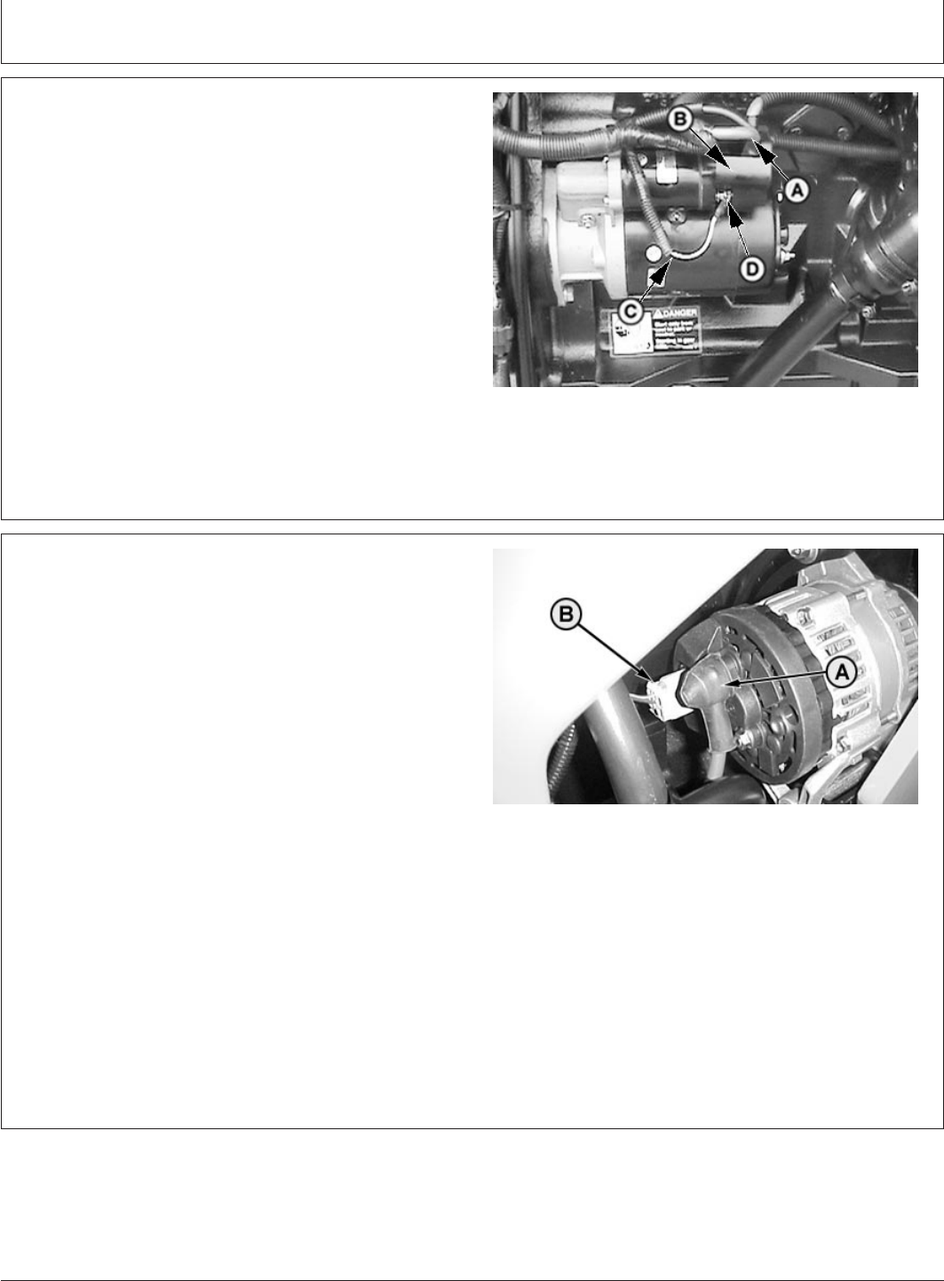
Service
PY80265,05I0268 –19–11JUL06–1/1
Connecting Starter Wiring
PY4876 –UN–12APR05
A—Large Battery Cable
B—Large Solenoid Post
C—Small White Wire
D—Solenoid Terminal
IMPORTANT: Disconnect battery negative (ground)
cable before servicing any part of
electrical system. Make all other
connections before connecting ground
cable.
Connect large battery cable (A) and alternator cable (B) to
large solenoid post. Connect the small white wire (C) to
solenoid terminal (D).
PY80265,05I0269 –19–12SEP05–1/1
Connecting Alternator Wiring
PY1658 –UN–15DEC05
A—Alternator Wire
B—Battery Charging Indicator Wire
IMPORTANT: Disconnect battery negative (ground)
cable before servicing any part of
electrical system. Make all other
connections before connecting ground
cable.
To prevent damage to electrical system,
disconnect alternator before making
any electrical weld repairs. If an
attached implement needs weld repair,
disconnect it from tractor before
welding, to prevent damage to tractor
electrical system.
If alternator is disconnected for any reason, connect wires
(A) and (B) as shown at right.
140-16
082206
PN=133
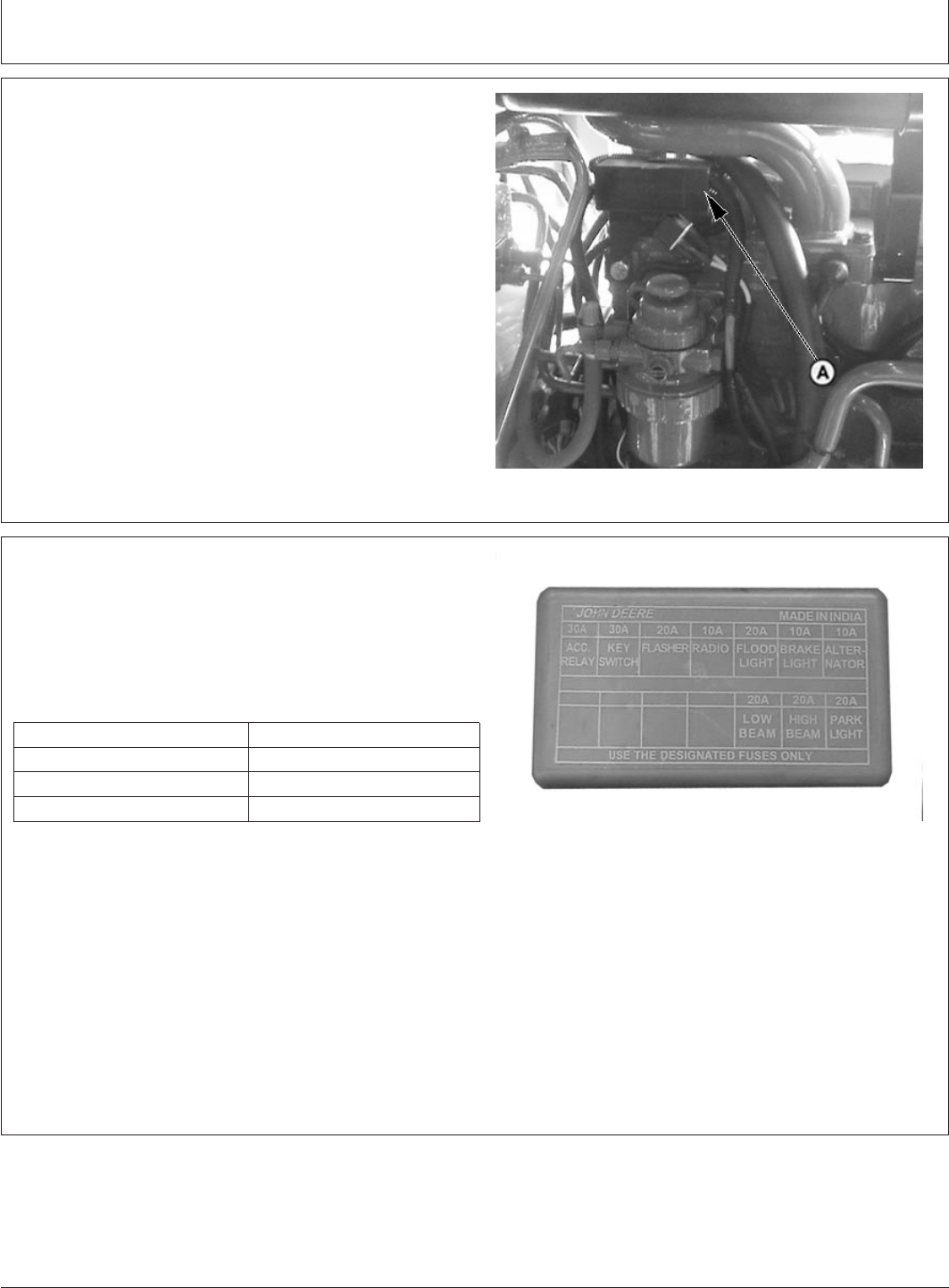
Service
PY80265,05I0270 –19–12SEP05–1/1
Locating Fusible Link
PY4439 –UN–03JAN05
A—Fusible Link
Electrical circuits are protected by fusible link.
Fusible link (A) is located under hood on right-hand side
of tractor, above fuel filter.
PY80265,05I0271 –19–12SEP05–1/1
Locating Fuses
PY5151 –UN–21AUG05
All electrical circuits are protected by fuses. Amperage
rating is marked on each fuse, plus fuses are color coded
to ensure proper replacement.
To access fuse panel , just pull out fuse panel cover.
Fuse Rating Color
10 Amp Red
20 Amp Yellow
30 Amp Green
IMPORTANT: DO NOT replace original fuse with
higher rated fuse or machine damage
may occur. If original size fuse will not
carry electrical load and continues to
blow, have the electrical system
checked by your John Deere dealer.
140-17
082206
PN=134
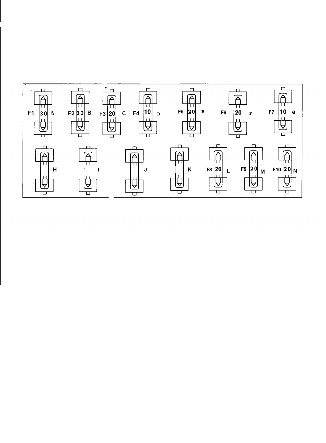
Service
PY80265,05I0272 –19–12SEP05–1/1
Fuse Size and Function
PY2235 –UN–16MAR04
A—30 amp—Accessory Relay D—10 amp—Radio G—10 amp—Alternator M—20 amp—High Beam Light
B—30 amp—Key switch E—20 amp—Flood light L—20 amp—Low Beam Light N—20 amp—Park light
C—20 amp—Flasher F—10 amp—Brake Light
140-18
082206
PN=135
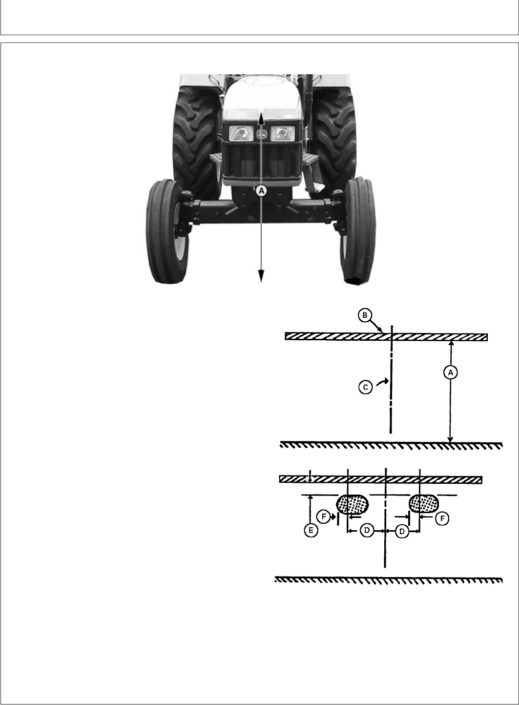
Service
PY80265,05I0273 –19–12SEP05–1/2
Aiming Headlights
PY4034 –UN–22JUL04
LV3020 –UN–10JUN99
A—Hood-to-Ground Distance
B—Masking Tape
C—Tractor Centerline
D—Center of Headlight
E—Top of Zone
F—Left Edge of Zone
1. Park tractor on level ground, with lights 8 m (25 ft)
from a wall.
2. Measure from top of hood to the ground (A). Place a
strip of masking tape (B) on the wall at the same
height.
3. Place a piece of tape, folded in the middle to make a
point, on the top front center of the hood.
4. Using the hood tape as a guide, sight across steering
wheel and hood to locate tractor centerline. Mark
tractor centerline (C) on wall.
5. From tractor centerline (C), mark a point 130 mm (5
in.) out in each direction (D). This mark locates a point
directly in front of center of each headlight.
6. Turn light switch to dim position.
140-19
082206
PN=136
Continued on next page
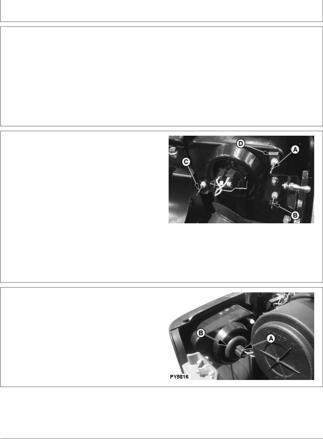
Service
PY80265,05I0273 –19–12SEP05–2/2
7. Locate small zone of bright light projected by each
lamp. Cover other lamps if necessary. Top of zone (E)
should be 130 mm (5 in.) below the tape. Left edge of
zone (F) should be 130 mm (5 in.) left of lamp location
marked (D).
8. To adjust headlights, see Adjusting Headlights in this
section.
PY80265,05I0274 –19–12SEP05–1/1
Adjusting Headlights
PY4104 –UN–12DEC05
A—Headlight Mounting Screw
B—Headlight Mounting Screw
C—Headlight Mounting Screw
D—Clips
1. Open the hood.
2. Turn screws (A—C) counterclockwise to lower beam or
clockwise to raise beam.
3. To adjust beam in toward center of tractor, turn screw
(A) counterclockwise and screws (B and C) clockwise
an equal number of turns on each screw.
4. To adjust beam out from center of tractor, turn screws
(B and C) counterclockwise and screw (A) clockwise
an equal number of turns on each screw.
NOTE: Clips (D) need not be removed for adjustment.
PY80265,05I0275 –19–28JUN06–1/2
Replace Headlight Bulb
PY5816 –UN–19JUN06
A—Headlight Connector
B—Dust Boot
1. Remove headlight connector (A).
2. Remove dust boot (B).
Continued on next page
140-20
082206
PN=137
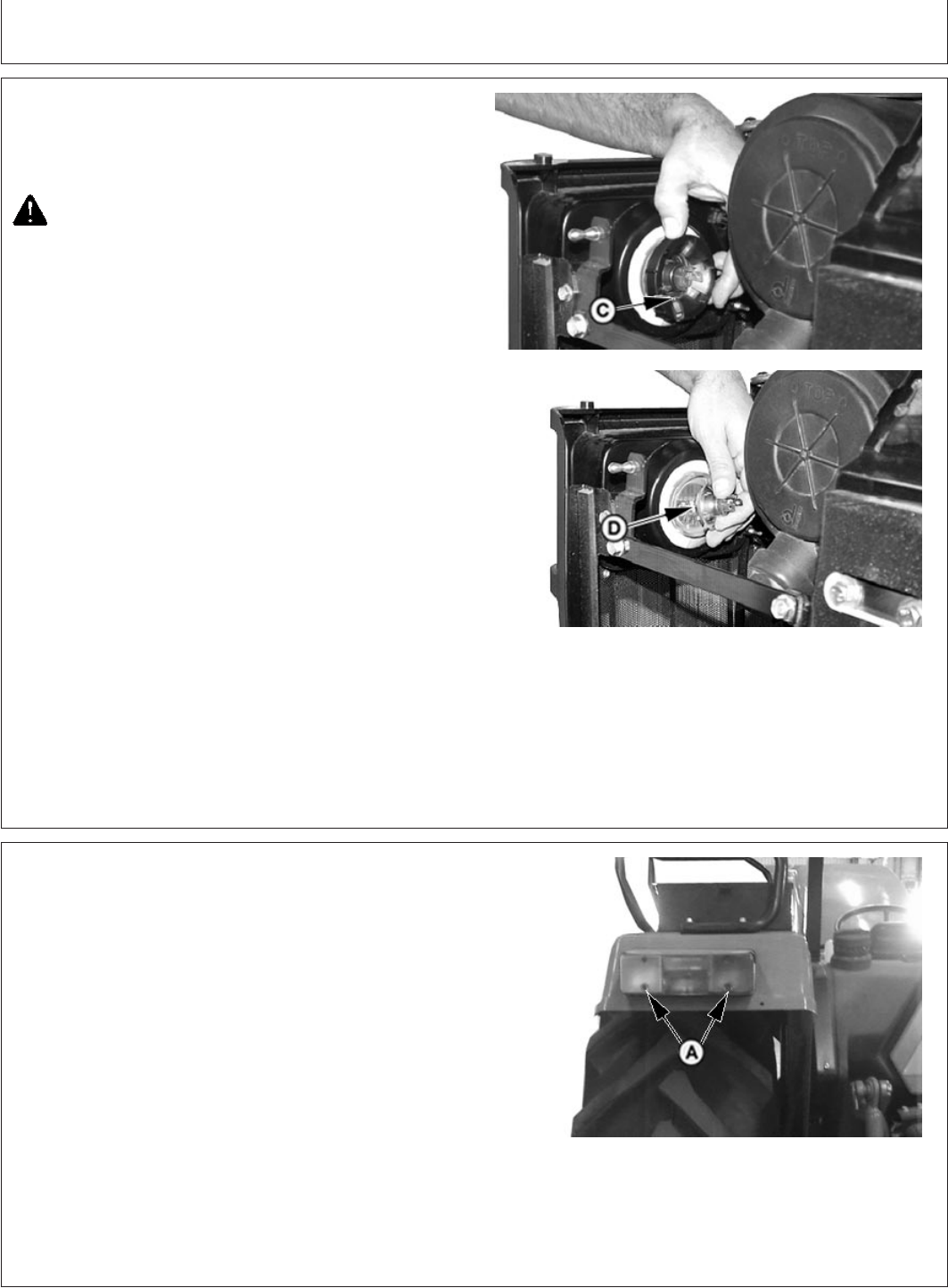
Service
PY80265,05I0275 –19–28JUN06–2/2
PY4921 –UN–12DEC05PY4922 –UN–12DEC05
C—Collar
D—Bulb
3. Twist collar (C).
4. Remove bulb (D).
CAUTION: A halogen bulb is pressurized and
may shatter. Protect bulb against abrasions and
scratches.
To guard against personal injury, wear
protective eyeglasses and clothing when
handling bulb. Turn power off when installing
and before removing bulb. Dispose of bulb with
care.
Allow bulb to cool before removing.
Read and follow all bulb manufacturers
installation instructions.
5. Install bulb, collar, seal and connector in reverse order.
PY80265,05I0276 –19–12SEP05–1/1
Replace Tail Light and Warning Light Bulbs
PY4362 –UN–29DEC04
A— Cap Screws (2 used)
1. Remove screws (A ).
2. Remove lens.
3. Push and twist to release bulb from socket.
4. Reverse this procedure to reassemble light.
140-21
082206
PN=138

Service
PY80265,05I0277 –19–12SEP05–1/1
Replace Flood Lamp Bulb
PY1080 –UN–02JUL01
1. Loosen mounting hardware (A) and rotate flood lamp
up to access cover fastening screw
2. Remove screw, lamp cover and lamp from housing
3. Disconnect wiring leads from bulb
4. Rotate bulb counterclockwise and remove
5. Reverse the procedure to reassemble the flood lamp
PY80265,05I0278 –19–12SEP05–1/1
Checking Tyres
1. Check tyres daily for damage or noticeably low
pressure.
2. Have any cuts or breaks repaired as soon as
possible.
3. Protect tyres from exposure to sunlight, petroleum
products and chemicals.
4. Drive carefully. Try to avoid rocks and sharp
objects.
IMPORTANT: Minimum pressures may be used
only for light loads and only if
tractor has no added weight. If you
install ballast or mounted
implements, or if you pull heavy
loads, increase pressure.
5. If tyre contains liquid ballast, jack up the rear wheel
and measure tyre pressure keeping valve stem at
topmost position.
Refer to Tyre Inflation Pressure Chart in Wheels,
Tyres and Treads section.
140-22
082206
PN=139

Troubleshooting
PY80265,05I0279 –19–12SEP05–1/4
Engine Troubleshooting
Symptom Problem Solution
Engine hard to start or will not Improper starting procedure. Reviewing starting procedure.
start
No fuel. Check fuel tank.
Air in fuel tank. Bleed fuel tank.
Hand primer left raised. Push primer down.
Slow starter speed. See “Starter Cranks Slowly”.
Crankcase oil too heavy. Use oil of proper viscosity.
Improper type of fuel. Consult fuel supplier; use proper
type fuel for operating conditions.
Water, dirt, or air in fuel system. Drain, flush, fill and bleed system.
Clogged fuel filter. Replace clogged filter insert (s)
Dirty or faulty injectors. Have John Deere dealer check
injectors.
Injection pump shut-off not reset. Turn key switch to OFF then to ON.
Fuel shut-off valve closed. Open Fuel shut-off valve on Fuel
tank and Fuel filter both.
Engine knocks Insufficient oil. Add oil.
Injection pump out of time. See your John Deere dealer.
Low coolant temperature. See your John Deere dealer.
Engine overheating. See “Engine Overheats”.
Continued on next page
145-1
082206
PN=140

Troubleshooting
PY80265,05I0279 –19–12SEP05–2/4
Symptom Problem Solution
Engine runs irregularly or stalls Low coolant temperature. See your John Deere dealer.
frequently
Clogged fuel filter. Replace clogged filter.
Water, dirt, or air in fuel system. Drain, flush, fill, and bleed system.
Dirty or faulty injectors. Have John Deere dealer check
injectors.
Improper type of fuel. Use proper fuel.
Below normal engine Defective temperature gauge or Check gauge, sender, and
temperature sender. conditions.
Lack of power Engine overloaded. Reduce load or shift to lower gear.
Low fast idle speed. See your John Deere dealer.
Intake air restriction. Service air cleaner.
Clogged fuel filter. Replace filter element.
Improper type of fuel. Use proper fuel.
Overheated engine. See “Engine Overheats”.
Below normal engine temperature. See your John Deere dealer.
Improper valve clearance. See your John Deere dealer.
Dirty or faulty injectors. Have John Deere dealer check
injectors.
Injection pump out of time. See your John Deere dealer.
Turbocharger not functioning . See your John Deere dealer.
Implement improperly adjusted. See implement operator’s manual.
Restricted fuel line. See your John Deere dealer.
Restricted return line. See your John Deere dealer.
Improper ballast. Adjust ballast to load.
145-2
082206
PN=141
Continued on next page

Troubleshooting
PY80265,05I0279 –19–12SEP05–3/4
Symptom Problem Solution
Low oil pressure Low oil level. Add oil.
Improper type of oil. Drain, fill crankcase with oil of proper
viscosity and quality.
High oil consumption Crankcase oil too light. Use proper viscosity oil.
Oil leaks. Check for leaks in lines, around
gaskets and drain plugs.
Restricted crankcase vent tube. Clean vent tube.
Engine emits white smoke Improper type fuel. Use proper fuel.
Low engine temperature. Warm up engine to normal operating
temperature.
Defective thermostat. See your John Deere dealer.
Defective injection nozzles. See your John Deere dealer.
Engine out of time. See your John Deere dealer.
Cold start advance or light load See your John Deere dealer.
advance not functioning.
Turbocharger not functioning. See your John Deere dealer.
Engine emits black or gray Improper type of fuel. Use proper fuel.
exhaust smoke
Clogged or dirty air cleaner. Service air cleaner.
Engine overloaded. Reduce load or shift to a low gear.
Injection nozzles dirty. See your John Deere dealer.
Engine out of time. See your John Deere dealer.
Continued on next page
145-3
082206
PN=142

Troubleshooting
PY80265,05I0279 –19–12SEP05–4/4
Symptom Problem Solution
Engine overheats Dirty radiator core, or grille screens. Remove all trash.
Engine overloaded. Shift to lower gear or reduce load.
Low engine oil level. Check oil level. Add oil as required.
Low coolant level. Fill radiator to proper level, check
radiator, and hoses for loose
connection or leaks.
Faulty radiator cap. Replace cap.
Loose or defective fan belt(s). Adjust belt tension(s).
Cooling system needs flushing. Flush cooling system.
Defective thermostat. See your John Deere dealer.
Defective temperature gauge or See your John Deere dealer.
sender.
Incorrect grade of fuel. Use proper fuel.
High fuel consumption. Improper type of fuel. Use proper fuel.
Clogged or dirty air cleaner. Service air cleaner.
Engine overloaded. Reduce load or shift to a lower gear.
Improper valve clearance. See your John Deere dealer.
Injection nozzles dirty. See your John Deere dealer.
Engine out of time. See your John Deere dealer.
Implement improperly adjusted. See implement operator’s manual.
Low engine temperature. See your John Deere dealer.
Excessive ballast. Adjust ballast to load.
Restricted air intake system. Check system.
Plugged crankcase vent tube. Clean vent tube.
145-4
082206
PN=143

Troubleshooting
PY80265,05I0280 –19–12SEP05–1/1
Transmission Troubleshooting
Symptom Problem Solution
Transmission oil overheats Low oil supply. Fill system with correct oil.
Clogged transmission-hydraulic oil Replace filter.
filter.
Internal hydraulic leak. See your John Deere dealer.
Hitch feedback linkage improperly Reset linkage. See your John Deere
adjusted. dealer.
Hydraulic motor not plumbed See your John Deere dealer.
correctly.
Low transmission pressure. Low oil supply. Fill system with correct oil.
Clogged transmission-hydraulic oil Replace filter.
filter.
145-5
082206
PN=144

Troubleshooting
PY80265,05I0281 –19–12SEP05–1/1
Hydraulic System Troubleshooting
Symptom Problem Solution
Hydraulic system fails to Low oil supply. Fill system with correct oil.
function
Clogged transmission-hydraulic filter. Replace filter.
Clogged transmission-hydraulic Clean pickup screen.
pickup screen.
High-pressure internal leak. See your John Deere dealer.
Hitch fails to lift or lift slowly Open preselector valve
Hydraulic oil overheats Low oil supply. Fill system with correct oil.
Clogged transmission-hydraulic oil Replace filter.
filter.
Internal hydraulic leak. See your John Deere dealer.
Oil passage to cylinder closed Open preselector valve
Hitch feedback linkage improperly Reset linkage. See your John Deere
adjusted. dealer.
PY80265,05I0282 –19–12SEP05–1/1
Brakes Troubleshooting
Symptom Problem Solution
No solid pedal feel Pedals adjusted incorrectly. See your John Deere dealer.
Excessive pedal travel Pedals adjusted incorrectly. See your John Deere dealer.
Brakes drag during transport Brakes out of adjustment. See your John Deere dealer.
145-6
082206
PN=145

Troubleshooting
PY80265,05I0283 –19–12SEP05–1/2
Rockshaft and 3-Point Hitch Troubleshooting
Symptom Problem Solution
Insufficient transport clearance Center link too long. Adjust center link.
Lift links to long. Adjust lift links.
Implement not level. Level implement.
Implement not properly adjusted. See implement operator’s manual.
Front of center link in upper holes. Move center link to lower holes.
Sway chains adjusted to short. Lengthen sway chains.
Hitch drops slowly Rockshaft rate-of-drop control not Adjust rate-of-drop knob.
properly set.
Hitch fails to lift or lifts slowly Excessive load on hitch. Reduce load.
Low oil level. Fill system with proper oil.
Hydraulic oil too cold. Allow oil to warm.
Transmission-hydraulic oil filter Replace filter.
clogged.
Transmission-hydraulic pickup Clean or replace pickup screen.
screen clogged.
Implement will not operate at Lift links too short. Adjust lift links.
desired depth
Lack of penetration. See implement operator’s manual.
Improper setting of limit stop. Reset position limit.
Improper setting of draft lever. See Rockshaft and 3-Point Hitch
section.
Continued on next page
145-7
082206
PN=146

Troubleshooting
PY80265,05I0283 –19–12SEP05–2/2
Symptom Problem Solution
Insufficient or no hitch response Front attachment of center link in Move center link attachment to lower
to draft load upper holes. bracket holes.
Draft control lever in “Off” position. Move lever rearward.
Lift links too short. Adjust lift links.
Lack of penetration. See implement operator’s manual.
Rate-of-drop too slow. Adjust rate-of-drop valve.
Hitch too responsive Front attachment on center link in Move center link attachment to
lower bracket holes. upper bracket holes.
Improper draft sensing adjustment. Move lever forward.
Hitch drops too fast Rate-of-drop set too fast. Adjust rate-of-drop.
Rockshaft control levers “drift”. Friction disks are loose. Adjust rockshaft control lever friction.
Levers too loose. See procedures in “Rockshaft and
3-Point Hitch” section or see your
John Deere dealer.
145-8
082206
PN=147

Troubleshooting
PY80265,05I0284 –19–12SEP05–1/2
Electrical System Troubleshooting
Symptom Problem Solution
Battery will not charge Loose or corroded connections. Clean and tighten connections.
Sulfated or worn-out battery. Check electrolyte level and specific
gravity.
Loose or defective alternator/fan Adjust belt tension or replace belt.
belt.
Charging system indicator glows Low engine speed. Increase speed.
with engine running
Defective battery. Check electrolyte level and specific
gravity.
Defective alternator. See your John Deere dealer.
Slipping alternator/fan belt. Adjust belt tension.
Starter inoperative Range shift lever in gear. Move lever to neutral.
PTO lever in engaged position. Move PTO lever to disengaged
position.
Low battery output. See your John Deere dealer.
Blown fuse. Replace fuse.
Starter cranks slowly Low battery output. Check electrolyte level and specific
gravity.
Crankcase oil too heavy. Use proper viscosity oil.
Loose or corroded connections. Clean and tighten loose connections.
Light system does not function; Blown fuse. Replace fuse.
rest of electrical system
functions
Continued on next page
145-9
082206
PN=148

Troubleshooting
PY80265,05I0284 –19–12SEP05–2/2
Symptom Problem Solution
Entire electrical system does not Faulty battery connections. Clean and tighten connections.
function
Sulfated or worn-out battery. Check electrolyte level and specific
gravity.
Blown fuse. Replace fuse.
Relay(s) sticking or Diode to protect circuit from arcing See your John Deere dealer.
nonfunctional; repeated failures has failed.
145-10
082206
PN=149
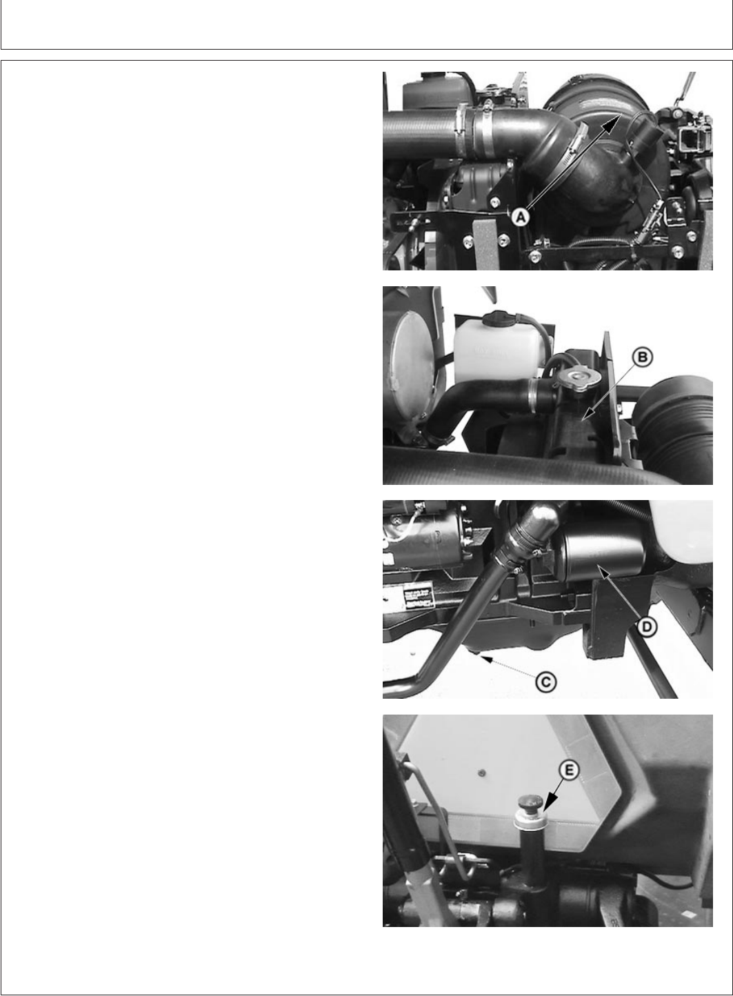
Tractor Storage
GENERIC,0000059 –19–11JUL06–1/2
Storing Tractor
PY4442 –UN–12DEC05PY4168 –UN–12DEC05PY4169 –UN–12DEC05PY4946 –UN–21APR05
A—Air Cleaner
B—Cooling System
C—Engine Oil Drain Plug
D—Engine Oil Filter
E—Transmission-Hydraulic Oil Filler Cap
IMPORTANT: Any time tractor will not be used for
several months, use this procedure to
minimize corrosion and deterioration.
1. Service air cleaner (A). (See Servicing Air Cleaner in
Service section.)
2. If coolant has been in tractor for two years, flush
cooling system (B). (See Flushing Cooling System in
Service section.) Add 50 percent antifreeze water
mixture. Test coolant for adequate cold weather
protection.
3. Change engine oil and filter (D). (See Change Engine
Oil and Filter in Service—250 Hours section.)
4. Drain fuel and add back4Loffuel. Then add 0.4 L of
corrosion inhibitor.
5. Add 0.25 L of corrosion inhibitor to
transmission-hydraulic system fill port (E).
6. Depress clutch and start engine. Run engine until it
reaches operating temperature. Also raise and lower
rockshaft several times. Shut off engine.
150-1
082206
PN=150
Continued on next page
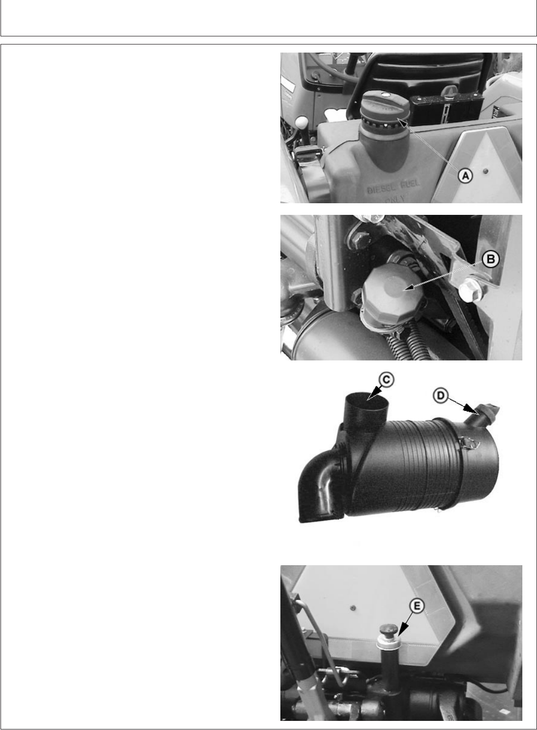
Tractor Storage
GENERIC,0000059 –19–11JUL06–2/2
PY4101 –UN–20AUG04PY1418 –UN–03FEB03PY5515 –UN–17FEB06PY4946 –UN–21APR05
A—Fuel Tank Filler Cap
B—Engine Oil Filler Cap
C—Air Cleaner Inlet Hole
D—Dust Unloader Valve
E—Transmission-Hydraulic Filler Cap
7. Add 0.5 L more inhibitor to fuel tank at filler cap (A).
8. Add 0.5 L inhibitor to engine crankcase at filler (B).
9. Remove air intake hose at manifold. Pour 0.1 L
inhibitor into manifold and replace hose. Pull hand
throttle back to slow idle position. Crank engine only a
few revolutions.
10. Loosen alternator/fan belt after they have cooled.
11. Remove and clean battery. Store in a cool, dry place.
Keep it charged.
1
12. Tie or block clutch pedal in the disengaged position.
13. Coat exposed bare (no paint) metal surfaces with
grease or a corrosion inhibitor.
14. Use tape to seal air inlet hole (C), dust unloader valve
(D), exhaust pipe, crankcase filler (B), fuel caps, and
transmission-hydraulic system filler cap (E).
15. Cover dash with opaque material to prevent gauges
from fading.
16. Raise tyres off ground. Protect them from heat and
sunlight.
17. Thoroughly clean tractor. Touch up any painted
surfaces that are scratched or chipped.
18. If tractor must be stored outside, cover it with a
waterproof material.
1
Disconnect battery ground cable for short-term storage periods (20 to
90 days).
150-2
082206
PN=151
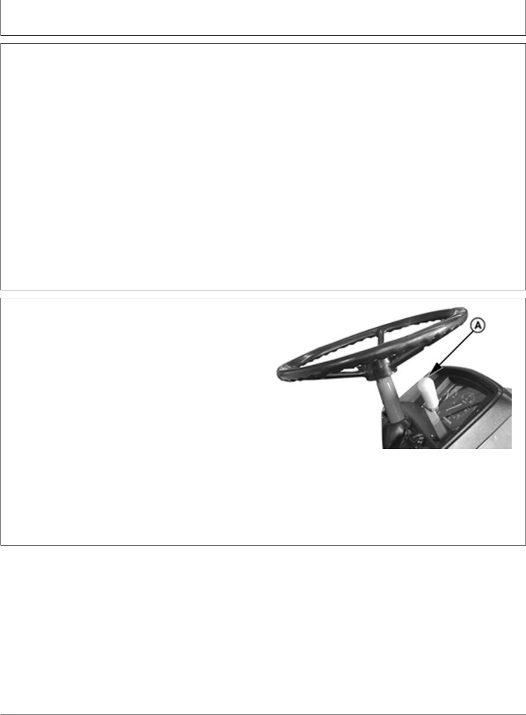
Tractor Storage
PY80265,05I0286 –19–11JUL06–1/2
Removing Tractor From Storage
1. Check tyre inflation pressure. (See Wheels, Tyres
and Treads section.) Lower tyres to ground.
2. Unseal all openings sealed in “Storing Tractor”.
3. Install battery.
4. Remove ties or block which secured clutch pedal
down.
5. Check levels of engine oil, transmission-hydraulic
oil and engine coolant, Add if necessary.
6. Drain a small amount of fuel from fuel tank to purge
any moisture condensation that has collected.
7. Fill fuel tank.
8. Perform all appropriate 10-hour, 50-hour, 250-hour,
and 600-hour services as instructed in Lubrication
and Maintenance section.
9. Check all instruments and indicators by turning key
switch to ON position.
PY80265,05I0286 –19–11JUL06–2/2
PY4485 –UN–16FEB06
A—Hand Throttle
IMPORTANT: DO NOT operate starter more than 20
seconds at a time and wait at least two
minutes for starter to cool before trying
again.
10. Pull hand throttle (A) all the way down, depress clutch
pedal and crank engine until oil pressure rises.
11. Connect wiring lead to fuel injection pump shut-off
solenoid.
12. Depress clutch pedal and start engine. Operate
engine at slow idle for several minutes. Warm up
carefully and check all systems before placing tractor
under load.
150-3
082206
PN=152

Specifications
GENERIC,0000043 –19–17FEB06–1/1
John Deere 5310 S Tractor
5310 S-3029T Turbocharged Engine
Observed PTO power 62 hp
Max. engine torque 240 Nm
Cylinders 3
Bore 106.5 mm
Stroke 110 mm
Displacement 2.9 L
Compression ratio 17.8:1
Firing order 1-2-3
Slow idle 800-875 RPM
Fast idle 2575-2650 RPM
Operating range 1400-2400
Injection pump timing 5.4°BTDC
Type of injection pump Rotary
Electrical
Battery 12 V, 100 AH
Alternator 43 Amp
Starter 12 V, 2.5 kW
Transmission
Clutch type Dual
Gearbox type Collar Shift
No. of forward gears 9
No. of reverse gears 3
Standard PTO 540 RPM
Dual PTO (Optional) 540 RPM @ 2376 & 1782 ERPM
Brakes
Type Wet disc brakes
Actuation Hydraulic
Hydraulics
Pump output 46 l/min
Lifting capacity 2000 kgf
Wheels and Tyres
Front tyre 6.5 x 20, 8 PR
Rear tyre 18.4 x 30, 14 PR
Dimensions and Weight
Total weight 2515 kg
Wheel base 2050 mm
Overall length 3820 mm
Overall width 1880 mm
Overall height (with exhaust pipe) 2300 mm
Ground clearance 500 mm
Turning radius w. brake 3150 mm
Turning radius w/o brake 3610 mm
Filling Capacities
Fuel tank 68 lit
Engine sump 8.5 lit
Transmission 38 lit
Hydraulics Common to transmission
155-1
082206
PN=153

Specifications
PY80265,05I0288 –19–12SEP05–1/1
Ground Speed at Rated Engine Speed (2400 RPM)
5310 S Tractor ( Rear tyre size : 18.4 X 30),(RR-753mm)
Gear Speed (km/h)
A1 2.72
A2 4.20
A3 4.92
B1 6.39
B2 9.94
B3 11.80
C1 17.57
C2 27.28
C3 32.41
A-R 3.86
B-R 9.13
C-R 25.07
155-2
082206
PN=154
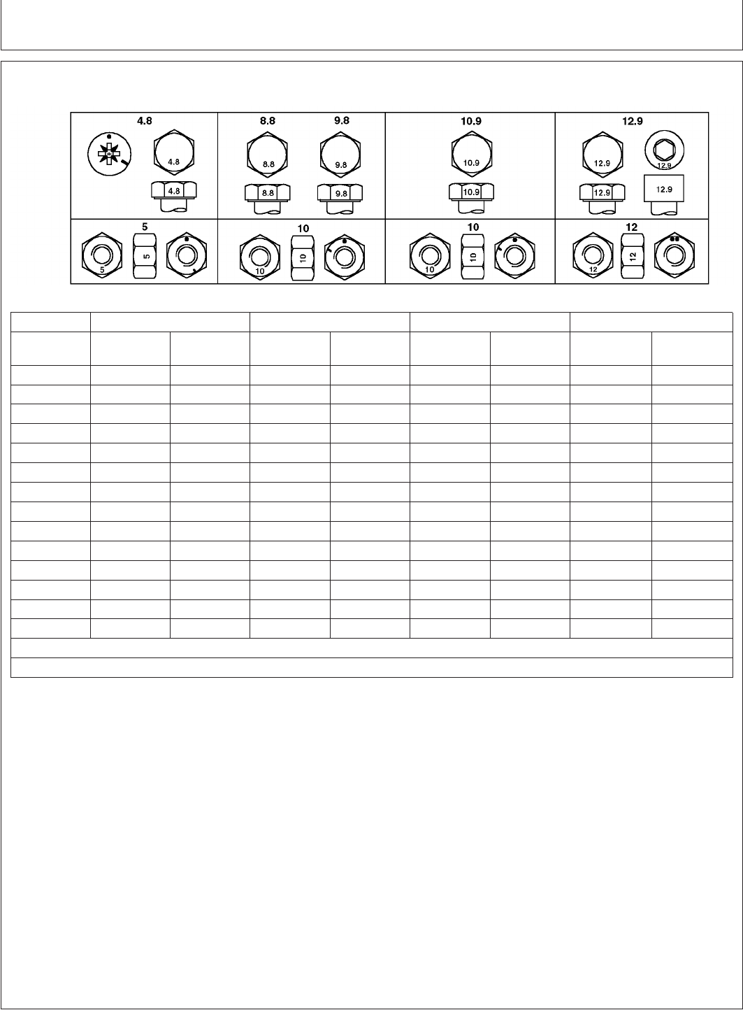
Specifications
PY80265,05I0289 –19–12SEP05–1/1
Metric Bolt and Cap Screw Torque Values
TORQ2 –UN–07SEP99
Top, property class and head markings; bottom, property class and nut markings
Class 4.8 Class 8.8 or 9.8 Class 10.9 Class 12.9
Size Lubricated
a
Dry
b
Lubricated
a
Dry
b
Lubricated
a
Dry
b
Lubricated
a
Dry
b
N•m(lb-ft) N•m(lb-ft) N•m(lb-ft) N•m(lb-ft) N•m(lb-ft) N•m(lb-ft) N•m(lb-ft) N•m(lb-ft)
M6 4.7 (3.5) 6 (4.4) 9 (6.6) 11.5 (8.5) 13 (9.5) 16.5 (12.2) 15.5 (11.5) 19.5 (14.5)
M8 11.5 (8.5) 14.5 (10.7) 22 (16) 28 (20.5) 32 (23.5) 40 (29.5) 37 (27.5) 47 (35)
M10 23 (17) 29 (21) 43 (32) 55 (40) 63 (46) 80 (59) 75 (55) 95 (70)
M12 40 (29.5) 50 (37) 75 (55) 95 (70) 110 (80) 140 (105) 130 (95) 165 (120)
M14 63 (46) 80 (59) 120 (88) 150 (110) 175 (130) 220 (165) 205 (150) 260 (190)
M16 100 (74) 125 (92) 190 (140) 240 (175) 275 (200) 350 (255) 320 (235) 400 (300)
M18 135 (100) 170 (125) 265 (195) 330 (245) 375 (275) 475 (350) 440 (325) 560 (410)
M20 190 (140) 245 (180) 375 (275) 475 (350) 530 (390) 675 (500) 625 (460) 790 (580)
M22 265 (195) 330 (245) 510 (375) 650 (480) 725 (535) 920 (680) 850 (625) 1080 (800)
M24 330 (245) 425 (315) 650 (480) 820 (600) 920 (680) 1150 (850) 1080 (800) 1350 (1000)
M27 490 (360) 625 (460) 950 (700) 1200 (885) 1350 (1000) 1700 (1250) 1580 (1160) 2000 (1475)
M30 660 (490) 850 (625) 1290 (950) 1630 (1200) 1850 (1350) 2300 (1700) 2140 (1580) 2700 (2000)
M33 900 (665) 1150 (850) 1750 (1300) 2200 (1625) 2500 (1850) 3150 (2325) 2900 (2150) 3700 (2730)
M36 1150 (850) 1450 (1075) 2250 (1650) 2850 (2100) 3200 (2350) 4050 (3000) 3750 (2770) 4750 (3500)
a
"Lubricated" means coated with a lubricant such as engine oil, or fasteners with phosphate and oil coatings.
b
"Dry" means plain or zinc plated without any lubrication.
DO NOT use these values if a different torque value or tightening Make sure fastener threads are clean and that you properly start
procedure is given for a specific application. Torque values listed are thread engagement. This will prevent them from failing when
for general use only. Check tightness of fasteners periodically. tightening.
Shear bolts are designed to fail under predetermined loads. Always Tighten plastic insert or crimped steel-type lock nuts to approximately
replace shear bolts with identical property class. 50 percent of the dry torque shown in the chart, applied to the nut,
not to the bolt head. Tighten toothed or serrated-type lock nuts to the
full torque value.
Fasteners should be replaced with the same or higher property class.
If higher property class fasteners are used, these should only be
tightened to the strength of the original.
155-3
082206
PN=155
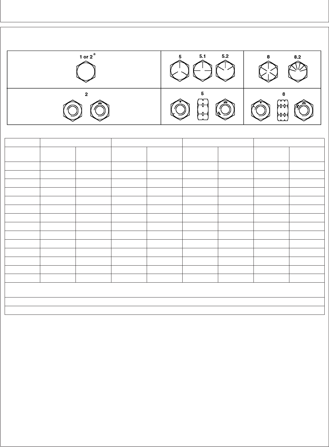
Specifications
PY80265,05I0290 –19–12SEP05–1/1
Unified Inch Bolt and Cap Screw Torque Values
TORQ1A –UN–27SEP99
Top, SAE grade and head markings; bottom, SAE grade and nut markings
Grade 1 (No Mark) Grade 2
a
(No Mark) Grade 5, 5.1 or 5.2 Grade 8 or 8.2
Size Lubricated
b
Dry
c
Lubricated
b
Dry
c
Lubricated
b
Dry
c
Lubricated
b
Dry
c
N•m(lb-ft) N•m(lb-ft) N•m(lb-ft) N•m(lb-ft) N•m(lb-ft) N•m(lb-ft) N•m(lb-ft) N•m(lb-ft)
1/4 3.8 (2.8) 4.7 (3.5) 6 (4.4) 7.5 (5.5) 9.5 (7) 12 (9) 13.5 (10) 17 (12.5)
5/16 7.7 (5.7) 9.8 (7.2) 12 (9) 15.5 (11.5) 19.5 (14.5) 25 (18.5) 28 (20.5) 35 (26)
3/8 13.5 (10) 17.5 (13) 22 (16) 27.5 (20) 35 (26) 44 (32.5) 49 (36) 63 (46)
7/16 22 (16) 28 (20.5) 35 (26) 44 (32.5) 56 (41) 70 (52) 80 (59) 100 (74)
1/2 34 (25) 42 (31) 53 (39) 67 (49) 85 (63) 110 (80) 120 (88) 155 (115)
9/16 48 (35.5) 60 (45) 76 (56) 95 (70) 125 (92) 155 (115) 175 (130) 220 (165)
5/8 67 (49) 85 (63) 105 (77) 135 (100) 170 (125) 215 (160) 240 (175) 305 (225)
3/4 120 (88) 150 (110) 190 (140) 240 (175) 300 (220) 380 (280) 425 (315) 540 (400)
7/8 190 (140) 240 (175) 190 (140) 240 (175) 490 (360) 615 (455) 690 (510) 870 (640)
1 285 (210) 360 (265) 285 (210) 360 (265) 730 (540) 920 (680) 1030 (760) 1300 (960)
1-1/8 400 (300) 510 (375) 400 (300) 510 (375) 910 (670) 1150 (850) 1450 (1075) 1850 (1350)
1-1/4 570 (420) 725 (535) 570 (420) 725 (535) 1280 (945) 1630 (1200) 2050 (1500) 2600 (1920)
1-3/8 750 (550) 950 (700) 750 (550) 950 (700) 1700 (1250) 2140 (1580) 2700 (2000) 3400 (2500)
1-1/2 990 (730) 1250 (930) 990 (730) 1250 (930) 2250 (1650) 2850 (2100) 3600 (2650) 4550 (3350)
a
Grade 2 applies for hex cap screws (not hex bolts) up to 6 in. (152 mm) long. Grade 1 applies for hex cap screws over 6 in. (152 mm) long,
and for all other types of bolts and screws of any length.
b
"Lubricated" means coated with a lubricant such as engine oil, or fasteners with phosphate and oil coatings.
c
"Dry" means plain or zinc plated without any lubrication.
DO NOT use these values if a different torque value or tightening Make sure fastener threads are clean and that you properly start
procedure is given for a specific application. Torque values listed are thread engagement. This will prevent them from failing when
for general use only. Check tightness of fasteners periodically. tightening.
Shear bolts are designed to fail under predetermined loads. Always Tighten plastic insert or crimped steel-type lock nuts to approximately
replace shear bolts with identical grade. 50 percent of the dry torque shown in the chart, applied to the nut,
not to the bolt head. Tighten toothed or serrated-type lock nuts to the
full torque value.
Fasteners should be replaced with the same or higher grade. If
higher grade fasteners are used, these should only be tightened to
the strength of the original.
155-4
082206
PN=156
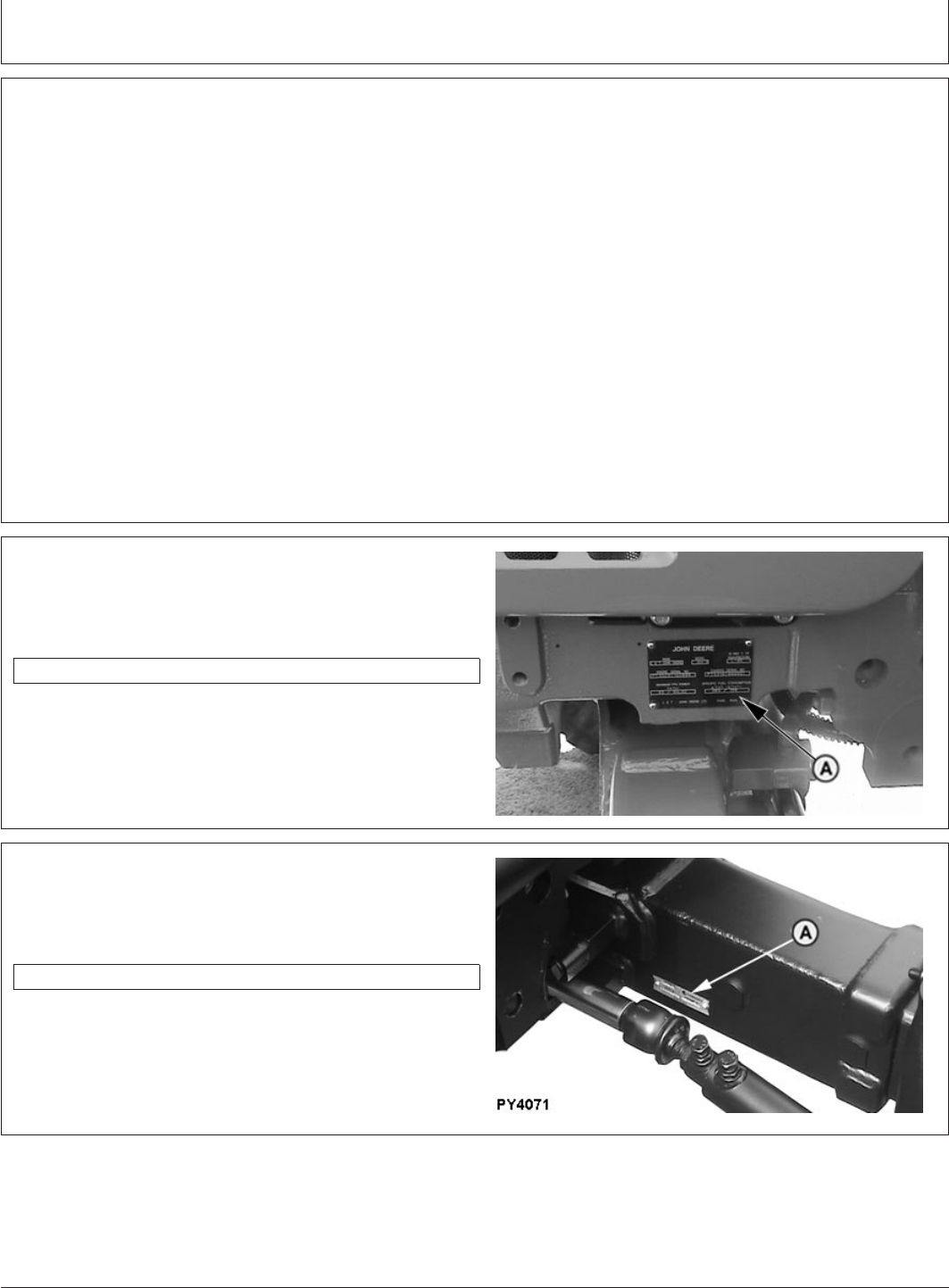
Identification Numbers
PY80265,05I0291 –19–12SEP05–1/1
Identification Plates
Each tractor has the identification plates shown on these
pages. The letters and numbers stamped on the plates
identify a component or assembly. ALL these characters
are needed when ordering parts or identifying a tractor or
component for any John Deere product support program.
Also, they are needed for law enforcement to trace your
tractor if it is ever stolen. ACCURATELY record these
characters in the spaces provided in each of the following
photographs.
PY80265,05I0292 –19–12SEP05–1/1
Record Tractor Serial (Chassis) Number
PY5153 –UN–21AUG05
Serial number plate (A) is located on the left front support
member of the tractor.
Tractor Serial Number
PY80265,05I0293 –19–12SEP05–1/1
Record Front Axle Serial Number
PY4071 –UN–07JUN06
The front-axle serial number plate (A) is located on rear
side of right-hand axle housing.
Front Axle Serial Number
160-1
082206
PN=157
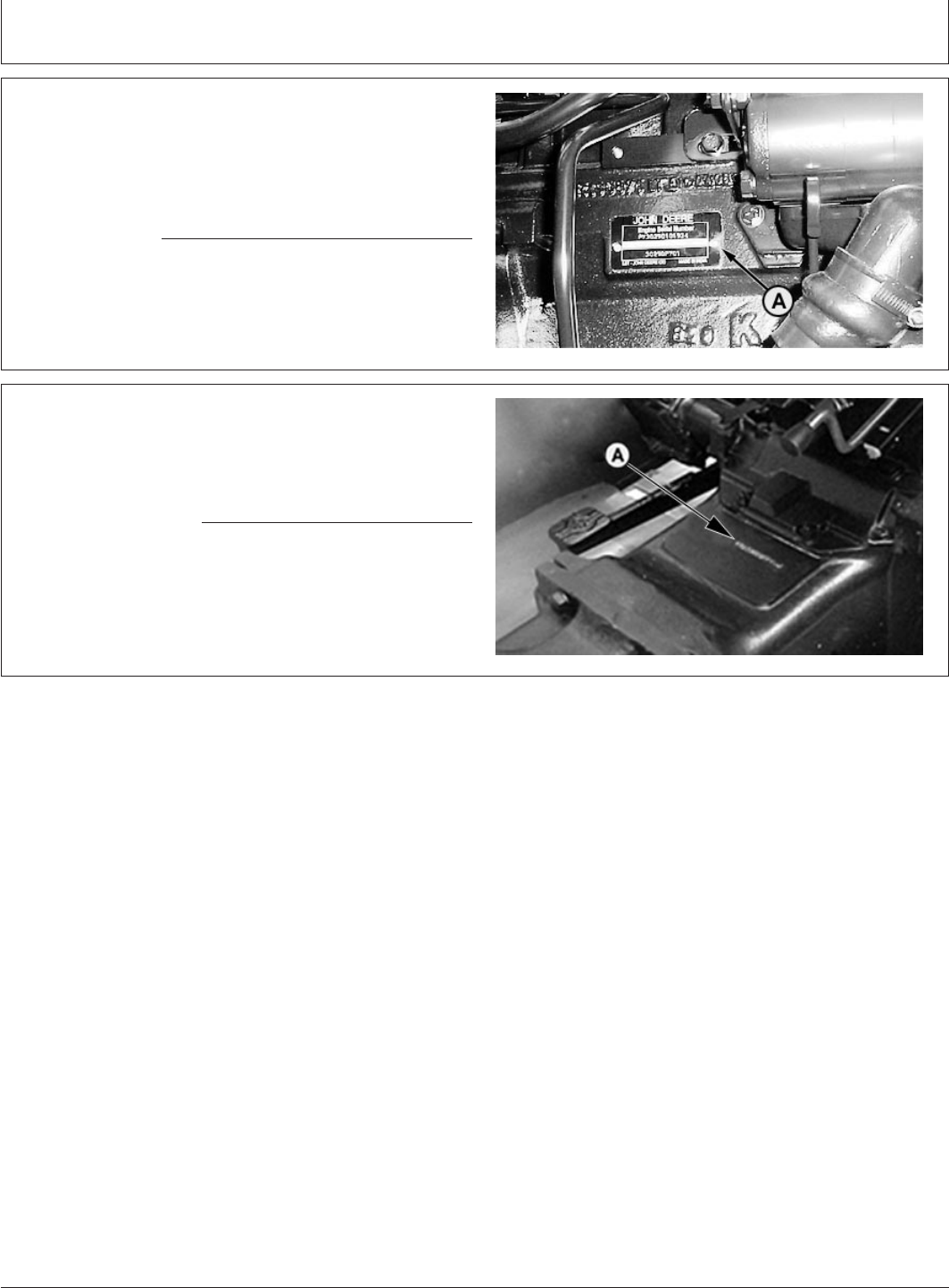
Identification Numbers
PY80265,05I0294 –19–12SEP05–1/1
Record Engine Serial Number
PY5154 –UN–21AUG05
Serial number plate (A) is located on the right-hand side
of the engine block between the starter solenoid and the
hydraulic pump.
Engine Serial Number
PY80265,05I0295 –19–12SEP05–1/1
Record Transmission Serial Number
PY1537 –UN–30JAN06
Transmission serial number is stamped into the lower
left-hand corner of rear housing (A).
Transmission Serial Number
160-2
082206
PN=158

Lubrication Maintenance Record Charts
PY80265,05I0296 –19–12SEP05–1/1
50, 250 Hour Service Chart
Every 50 Hours
•Check transmission-hydraulic system oil level
•Clean and check battery
•Inspect all tyres
•Lubricate front axle pivot pin
•Lubricate steering spindles
•Inspect tractor for loose nuts and bolts
Every 250 Hours
•Change engine oil and filter
•Service air cleaner
•Inspect and adjust alternator/fan belt
•Lubricate 3-point hitch
•Check neutral start system
•Check clutch pedal free play
•Check brake pedal adjustment
Hours Hours
Date Date
Date Date
Hours Hours
Date Date
Hours Hours
Date Date
Hours Hours
Date Date
Hours Hours
Date Date
Hours Hours
Date Date
Hours Hours
Date Date
Hours Hours
Date Date
Hours Hours
Date Date
165-1
082206
PN=159

Lubrication Maintenance Record Charts
PY80265,05I0297 –19–12SEP05–1/1
500 Hour Service Chart
Every 500 Hours
•Replace fuel filter
•Replace transmission-hydraulic oil filter
Hours Hours
Date Date
Hours Hours
Date Date
Hours Hours
Date Date
Hours Hours
Date Date
Hours Hours
Date Date
Hours Hours
Date Date
Hours Hours
Date Date
Hours Hours
Date Date
Hours Hours
Date Date
Hours Hours
Date Date
Hours Hours
Date Date
Hours Hours
Date Date
Hours Hours
Date Date
165-2
082206
PN=160

Lubrication Maintenance Record Charts
PY80265,05I0298 –19–12SEP05–1/1
600 Hour Service Chart
Every 600 Hours
•Clean crankcase vent tube
•Repack front wheel bearings
•Tighten engine air intake hose clamps
•Check cooling system for leaks
•Lubricate rear axle bearings
•Check engine idle speeds
•Have your John Deere dealer:
– Adjust engine valve clearance
– Check front axle pivot pin
– Inspect fuel injectors
Hours Hours
Date Date
Hours Hours
Date Date
Hours Hours
Date Date
Hours Hours
Date Date
Hours Hours
Date Date
Hours Hours
Date Date
Hours Hours
Date Date
Hours Hours
Date Date
Hours Hours
Date Date
Hours Hours
Date Date
Hours Hours
Date Date
Hours Hours
Date Date
Hours Hours
Date Date
165-3
082206
PN=161

Lubrication Maintenance Record Charts
PY80265,05I0299 –19–12SEP05–1/1
1000,1250 Hour Service Chart
Every 1000 Hours
•Check and adjust valve clearance
•Check engine speeds
Every 1250 Hours
•Change transmission-hydraulic oil and filter
•Clean transmission-hydraulic pickup screen
Hours Hours
Date Date
Hours Hours
Date Date
Hours Hours
Date Date
Hours Hours
Date Date
Hours Hours
Date Date
Hours Hours
Date Date
Hours Hours
Date Date
Hours Hours
Date Date
Hours Hours
Date Date
Hours Hours
Date Date
Hours Hours
Date Date
Hours Hours
Date Date
Hours Hours
Date Date
165-4
082206
PN=162

Lubrication Maintenance Record Charts
PY80265,05I0301 –19–12SEP05–1/1
Annual Service Chart
Annually
•Change engine oil and filter
•Replace air cleaner elements
Hours Hours
Date Date
Hours Hours
Date Date
Hours Hours
Date Date
Hours Hours
Date Date
Hours Hours
Date Date
Hours Hours
Date Date
Hours Hours
Date Date
Hours Hours
Date Date
Hours Hours
Date Date
Hours Hours
Date Date
Hours Hours
Date Date
Hours Hours
Date Date
Hours Hours
Date Date
165-5
082206
PN=163

Lubrication Maintenance Record Charts
PY80265,05I0302 –19–12SEP05–1/1
2000 Hour Service Chart
Every 2 Years or 2000 Hours (Whichever Comes
First) •Flush cooling system
Hours Hours
Date Date
Hours Hours
Date Date
Hours Hours
Date Date
Hours Hours
Date Date
Hours Hours
Date Date
Hours Hours
Date Date
Hours Hours
Date Date
Hours Hours
Date Date
Hours Hours
Date Date
Hours Hours
Date Date
Hours Hours
Date Date
Hours Hours
Date Date
165-6
082206
PN=164

Lubrication Maintenance Record Charts
PY80265,05I0303 –19–12SEP05–1/1
As Required Service Chart
Service as Required
•Replace fuel filter
•Drain water and sediment from fuel tank
•Service air cleaner
•Adjust throttle friction
Hours Hours
Date Date
Hours Hours
Date Date
Hours Hours
Date Date
Hours Hours
Date Date
Hours Hours
Date Date
Hours Hours
Date Date
Hours Hours
Date Date
Hours Hours
Date Date
Hours Hours
Date Date
Hours Hours
Date Date
Hours Hours
Date Date
Hours Hours
Date Date
Hours Hours
Date Date
165-7
082206
PN=165
F
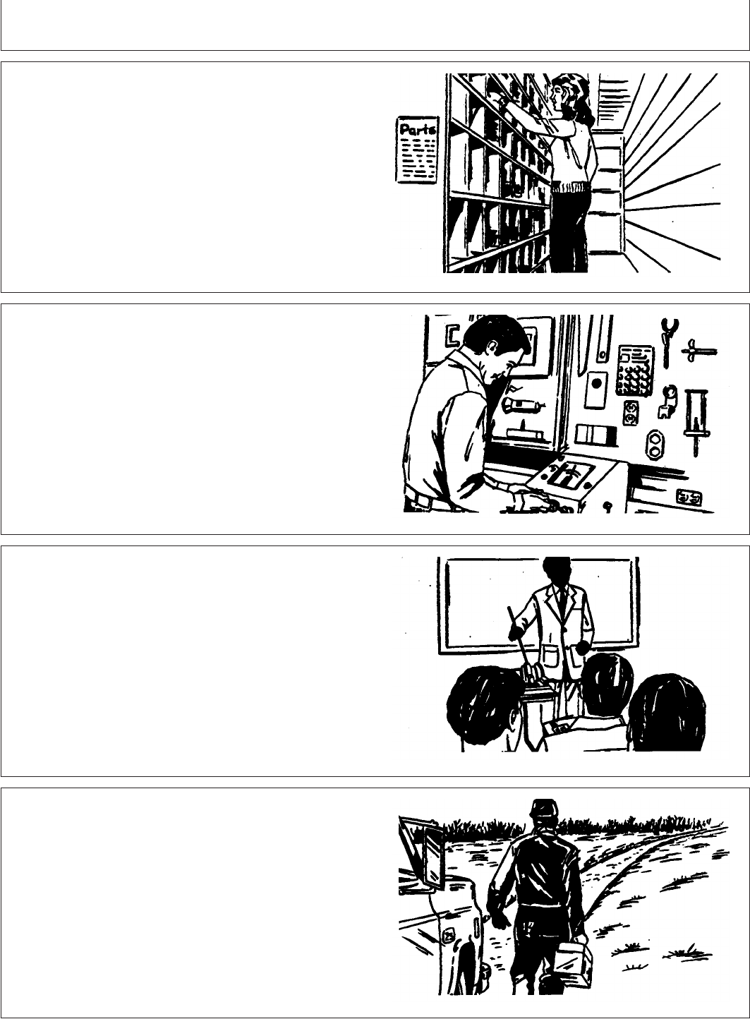
John Deere Service
PY00013,0000003 –19–14JUN01–1/1
John Deere Parts
TS100 –UN–23AUG88
We help minimize downtime by putting genuine John
Deere parts in your hands in a hurry. That’s why we
maintain a large and varied inventory to meet your spare
parts needs.
PY00013,0000004 –19–14JUN01–1/1
The Right Tools
TS101 –UN–23AUG88
Precision tools and testing equipment enable our Service
Department to locate and correct troubles quickly. They
save your time and money.
PY00013,0000005 –19–14JUN01–1/1
Well Trained Technician
TS102 –UN–23AUG88
School is never out for John Deere service technicians.
Training schools are held regularly to be sure our
personnel know your equipment and how to maintain it.
Result?
Experience you can count on!
PY00013,0000006 –19–14JUN01–1/1
Prompt Service
TS103 –UN–23AUG88
Our goal is to provide prompt, efficient care when you
want it and where you want it. We can make repairs at
your place or at ours, depending on the circumstances.
see us, depend on us.We’ll be around when you need us.
170-1
082206
PN=166

Index
Page Page
A
Brakes
Using ...............................50-4
Brakes troubleshooting...................145-6
Acid burns, battery .....................140-13 Break-in ...............................35-1
Adjusting rockshaft speed-of-drop Break-in service .....................35-1, 90-1
Implement lock ........................55-5
Air cleaner
Inspecting primary element ..............140-6
Replace elements .....................125-1
C
Service ........................110-2, 135-1
Service/regular intervals ................140-4 Cast iron weights ........................70-6
Storing primary element ................140-7 Install rear............................70-6
Air intake system Center link
Checking............................140-4 Positioning ...........................55-6
Components .........................140-3 Charging system indicator .................45-3
Air restriction indicator ....................45-4 Checking Toe-In ........................75-10
Alternator wiring Clutch pedal free play
Connecting .........................140-16 Check and adjust .....................110-4
Alternator/fan belt Connecting single acting cylinder ............60-3
Inspect and adjust.....................110-2 Control lever and coupler identification........60-1
Alternator/fan belt, replacing...............140-7 Coolant
Attaching implements to three point hitch ......55-7 Check level ...........................95-1
Attaching PTO-driven implement ............65-2 Diesel engine .........................85-4
Coolant temperature gauge ................45-4
Cooling system
B
Components .........................140-9
Flush every two years..................130-1
Correct hose tips ........................60-1
Ballast ................................70-1 Cylinder hoses, disconnecting ..............60-5
Limitations............................70-3 Cylinder, extending/retracting
Liquid weight..........................70-7 No.1SCV ...........................60-4
Matching to load work...................70-1
Maximum front ........................70-5
Maximum rear.........................70-5
Selecting.............................70-1
D
Ballasting ..............................70-5
Front end for transport ..................70-4 Dash panel.............................15-3
Battery Diesel engine
Access ............................140-11 Oil..................................85-2
Acid burn treatment...................140-13 Differential lock
Booster ..............................45-8 Using ...............................50-5
Charging ...........................140-15 Draft control, using .......................55-4
Checking condition ...................140-12 Drawbar
Clean and check......................100-1 Load limitations........................65-1
Removing ..........................140-12 Driving on public roads................50-1, 80-1
Replacement specifications.............140-15
Servicing...........................140-13
Battery explosion ......................140-12
Before starting the engine .................45-1
E
Bolts
Front axle, tighten ......................75-4
Rear axle, tighten ......................75-5 Electrical service precautions .............140-11
Electrical system troubleshooting ...........145-9Booster battery..........................45-8
Index-1
082206
PN=1

Index
Page Page
Engine Grille screens, cleaning .................140-10
Ground speed estimates..................155-2Avoid idling ...........................45-6
Break-in oil ..........................140-1
Change oil and filter ...................110-1
Changing speeds ......................45-5
H
Check idle speeds ....................115-3
Check oil level ........................95-1
Cooling system .......................140-9 Hardware
Observe work and idle speeds ............45-7 Wheel/axle, tighten .....................75-3
Stalled...............................45-6 Headlights .............................20-2
Stopping .............................45-8 Adjusting...........................140-20
Troubleshooting ......................145-1 Aiming.............................140-19
Warming up ..........................45-5 Replace bulb........................140-20
Engine crankcase vent tube High beam indicator ......................20-2
Clean ..............................115-1 Hitch
Engine valve clearance Adjusting side sway ....................55-8
Adjust ..............................115-3 Attaching implements to .................55-7
Components ..........................55-1
Leveling .............................55-9
Lubricate three-point ...................110-3
F
Hood
Opening ............................140-2
Fan/alternator belt, replacing ..............140-7 Removing ...........................140-3
Front axle pivot pin Hoses and hose clamps, check ............115-2
Check ..............................115-3 Hydraulic cylinder hoses, connecting .........60-2
Lubricate............................100-1 Hydraulic system troubleshooting ...........145-6
Front wheel bearings, pack ...............115-1 Hydraulic-transmission filter element .........85-5
Fuel
Fill tank..............................85-3
Storage..............................85-2
Watch level ...........................45-4
I
Fuel filter
Drain............................95-2, 95-3 Identification numbers....................160-1
Filter ...............................115-1 Idle speeds, check ......................115-3
Fuel system Implement to tyre clearance ................75-1
Bleeding ............................140-8 Inch torque values ......................155-4
Components .........................140-7 Indicator
Fuel tank Air restriction..........................45-4
Drain............................95-2, 95-3 Charging system.......................45-3
Fuels and lubricants ......................85-1 Oil pressure ..........................45-3
Fuses Instrument panel.........................15-3
Locating ...........................140-17
Size and function ....................140-18
Fusible link, locating ....................140-17
L
G
Lateral float, adjusting ...................55-10
Light
Hazard ..............................20-5Gauge
Coolant temperature ....................45-4 Light switch
Operation ............................20-1Gear oil ...............................85-5
Grease ................................85-6 Lighting and signals ......................20-1
Index-2
082206
PN=2

Index
Page Page
Lubricant Rockshaft and quick-coupler 3-point hitch
Troubleshooting ......................145-7Storage..............................85-3
Lubrication and maintenance record charts . . . 165-1 Rockshaft control lever friction, adjust .......55-10
Rockshaft control levers ...................55-2
MS
Metric torque values .....................155-3 Seat
Selecting position ......................25-1
Selecting a gear .........................50-4
N
Service
As required ..........................135-1
Neutral lever position .....................60-3 10 hours .............................95-1
Neutral start system, check ...............110-3 100 hours ...........................110-1
1200 hours ..........................120-1
250 hours ...........................110-2
50 hours ............................100-1
O
Service intervals.........................90-2
Service intervals, observe..................90-1
Oil Seven-terminal outlet .....................20-6
Engine break-in.......................140-1 Side screens, removing ..................140-3
Warming hydraulic system ..............55-11 Signals ................................20-1
Oil cooler, cleaning.....................140-10 Speed/hour meter........................45-7
Oil Gear ...............................85-5 Starter wiring, connecting ................140-16
Oil pressure indicator .....................45-3 Starting the engine .......................45-2
Operating transmission....................50-3 Steering spindles, lubricate................100-2
Operator training ........................50-1 Stopping tractor .........................50-6
Storing lubricants ........................85-3
Storing tractor..........................150-1
P
Position center link .......................55-6
T
Position control lever stop, setting ...........55-2
Prestart checks..........................40-1 Tail light ...............................20-3
PTO Replace bulb........................140-21
Adjusting clutch rod.....................65-5 Three-point hitch, lubricate ................110-3
Attach driven implement .................65-2 Throttle friction, adjust ...................135-1
Operating ........................65-3, 65-4 Tires
Inflation pressure ......................75-2
Inflation pressure chart ..................75-3
R
Toe-in, 2-WD tractor
Adjusting............................75-11
Torque valuesRadiator, cleaning......................140-10
Rear axle bearings, lubricate ..............115-2 Adjustable front axle ....................75-4
Inch................................155-4Removing tractor from storage .............150-3
Reversed cylinder response, correcting .......60-3 Metric ..............................155-3
Rear axle ............................75-5Ride comfort, adjusting....................25-1
Rockshaft Wheels/axles..........................75-3
Towing tractor ..........................80-4Postion control ........................55-3
Rate-of-dropadjustment.................55-5Tractorcontrols.........................15-1
Index-3
082206
PN=3

Index
Page Page
Tractor PTO, operating................65-3, 65-4 Wheel slip
Measuring manually ....................70-2Transmission troubleshooting ..............145-5
Transmission, operating ...................50-3
Transmission, shifting.....................50-3
Transmission-hydraulic system
Change oil and filter ...................120-1
Check oil level .......................100-1
Clean pickup screen ...................120-2
Replace filter.........................115-1
Transport ..............................80-4
Tractor ..............................05-8
Tread settings
Adjustable front axle—Late model tractor ....75-7
Multi-position rear wheels ................75-6
Tread width
Adjusting front axle, late model tractor ......75-9
Rear wheel limitations...................75-5
Troubleshooting
Brakes .............................145-6
Electrical system......................145-9
Engine .............................145-1
Hydraulic system......................145-6
Quick-coupler 3-point hitch ..............145-7
Rockshaft ...........................145-7
Transmission.........................145-5
Turn signals ............................20-4
Tyres
Checking...........................140-22
U
Using
Brakes ..............................50-4
Cast iron weights ......................70-6
Differential lock ........................50-5
Draft control ..........................55-4
Headlights............................20-2
Tail lights ............................20-3
Turn signals ..........................20-4
W
Warming hydraulic system oil..............55-11
Warning light
Replace bulb........................140-21
Weights
Cast iron .............................70-6
Install rear cast iron ....................70-6
Index-4
082206
PN=4
