John Deere Autotrac Ompfp11320 Users Manual
!! John-40 John Deere Lawn Mower Manuals - Lawn Mower Manuals – The Best Lawn Mower Manuals Collection
OMPFP11320 to the manual 68289d60-d1fb-4882-aa53-c69171c89195
2015-02-03
: John-Deere John-Deere-Autotrac-Ompfp11320-Users-Manual-466087 john-deere-autotrac-ompfp11320-users-manual-466087 john-deere pdf
Open the PDF directly: View PDF ![]() .
.
Page Count: 72
John Deere AutoTrac™
Controller—Raven™
OPERATOR'S MANUAL
John Deere AutoTrac™
Controller—Raven™
OMPFP11320 ISSUE H1 (ENGLISH)
CALIFORNIA
Proposition 65 Warning
Diesel engine exhaust and some of its constituents
are known to the State of California to cause cancer,
birth defects, and other reproductive harm.
If this product contains a gasoline engine:
WARNING
The engine exhaust from this product contains
chemicals known to the State of California to cause
cancer, birth defects or other reproductive harm.
The State of California requires the above two warnings.
Additional Proposition 65 Warnings can be found in this manual.
John Deere Ag Management Solutions
Worldwide Edition
PRINTED IN U.S.A.
DCYOMPFP11320

Introduction
OUO6050,0000FB1 -19-10AUG10-1/1
JS56696,0000A39 -19-14JUN11-1/1
www.StellarSupport.com
NOTE: Product functionality may not be fully represented in this document due to product changes occurring after the time of printing. Read the
latest Operator's Manual and Quick Reference Guide prior to operation. To obtain a copy, see your dealer or visit www.StellarSupport.com
Foreword
This AutoTrac Controller Operator's Manual is to be used
with the Guidance Operator's Manual.
READ BOTH MANUALS carefully to learn how to operate
and service your system correctly. Failure to do so could
result in personal injury or equipment damage. These
manuals may also be available in other languages. (See
your John Deere dealer to order.)
090811
PN=2

Contents
Page
Safety
Recognize Safety Information ............................05-1
Understand Signal Words...................................05-1
Follow Safety Instructions...................................05-1
Practice Safe Maintenance.................................05-2
Handle Electronic Components and
Brackets Safely ..............................................05-2
Use Seat Belt Properly .......................................05-3
Operate Guidance Systems Safely ....................05-3
Use AutoTrac Controller on Approved Vehicles ..05-3
Safety Signs
Automatic Guidance System Detected...............10-1
AutoTrac Controller
AutoTrac Accuracy .............................................15-1
General Information............................................15-1
AutoTrac Settings ...............................................15-2
Activity Monitor ...................................................15-2
AutoTrac Controller Troubleshooting
AutoTrac Controller ............................................20-1
Diagnostic Readings...........................................20-2
Stop Codes.........................................................20-3
AutoTrac Controller—Raven
AutoTrac Controller— Raven Calibration ...........25-1
Failed Calibrations..............................................25-8
Necessary Conditions for Activating AutoTrac ...25-9
AutoTrac Controller—Raven
Diagnostic Addresses ..................................25-10
AutoTrac Controller—Raven
Diagnostic Trouble Codes ............................25-12
GS2 Display 1800
Automatic Guidance System Detected...............30-1
Enabling System.................................................30-1
Activating System...............................................30-1
GreenStar Run Page..........................................30-2
Enabling AutoTrac ..............................................30-6
AutoTrac Status Pie............................................30-7
Reactivating AutoTrac on Next Pass..................30-8
Deactivating AutoTrac ........................................30-8
Guidance Settings ..............................................30-9
AutoTrac Settings .............................................30-10
Advanced AutoTrac Settings ............................30-13
StarFire ............................................................30-16
Page
Troubleshooting—GS2 Display 1800
Trouble Codes ....................................................35-1
Diagnostic Addresses.........................................35-1
Guidance Alarms................................................35-3
AutoTrac Deactivation Message.........................35-4
Diagnostic Addresses.........................................35-5
GS3 2630 Display
Automatic Guidance System Detected...............40-1
Enabling System.................................................40-2
Activating System...............................................40-3
Deactivating System...........................................40-3
Setup ..................................................................40-4
StarFire ..............................................................40-5
GS3 2630 Advanced Settings
Tuning Recommendations..................................45-1
Recommended Tuning Settings .........................45-3
Optimizing AutoTrac Controller Performance.....45-4
Tuning Tips, Tricks, and Precautions..................45-9
Troubleshooting..................................................45-9
Specications
Unied Inch Bolt and Screw Torque Values........50-1
Metric Bolt and Screw Torque Values.................50-2
EC Declaration of Conformity .............................50-3
Original Instructions. All information, illustrations and specications in this
manual are based on the latest information available at the time of publication.
The right is reserved to make changes at any time without notice.
COPYRIGHT © 2011
DEERE & COMPANY
Moline, Illinois
All rights reserved.
A John Deere ILLUSTRUCTION ® Manual
i090811
PN=1

Contents
ii 090811
PN=2
Safety
DX,ALERT -19-29SEP98-1/1
DX,SIGNAL -19-03MAR93-1/1
DX,READ -19-16JUN09-1/1
Recognize Safety Information
This is a safety-alert symbol. When you see this symbol
on your machine or in this manual, be alert to the potential
for personal injury.
Follow recommended precautions and safe operating
practices.
T81389 —UN—07DEC88
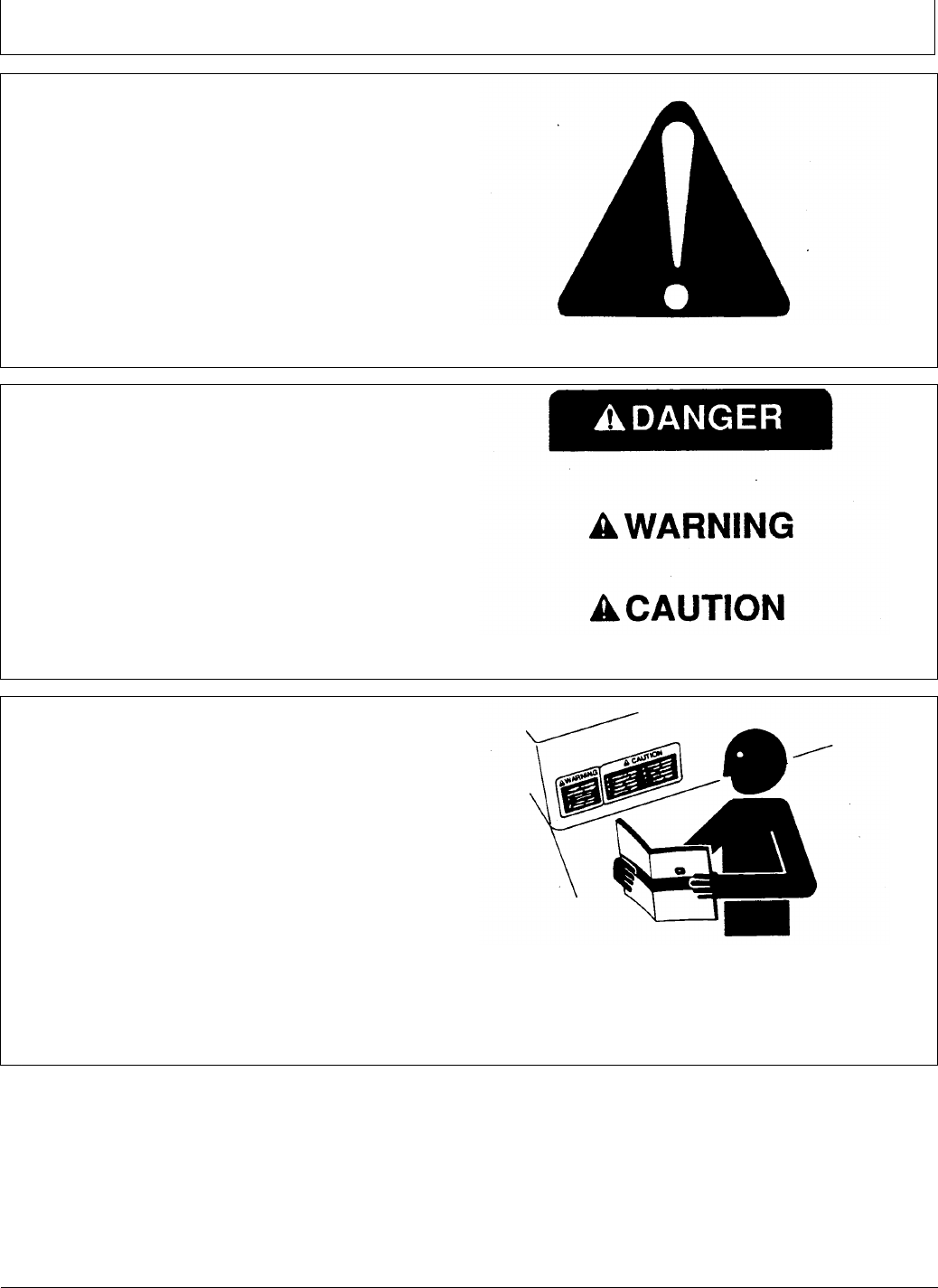
Understand Signal Words
A signal word—DANGER, WARNING, or CAUTION—is
used with the safety-alert symbol. DANGER identies the
most serious hazards.
DANGER or WARNING safety signs are located near
specic hazards. General precautions are listed on
CAUTION safety signs. CAUTION also calls attention to
safety messages in this manual.
TS187 —19—30SEP88
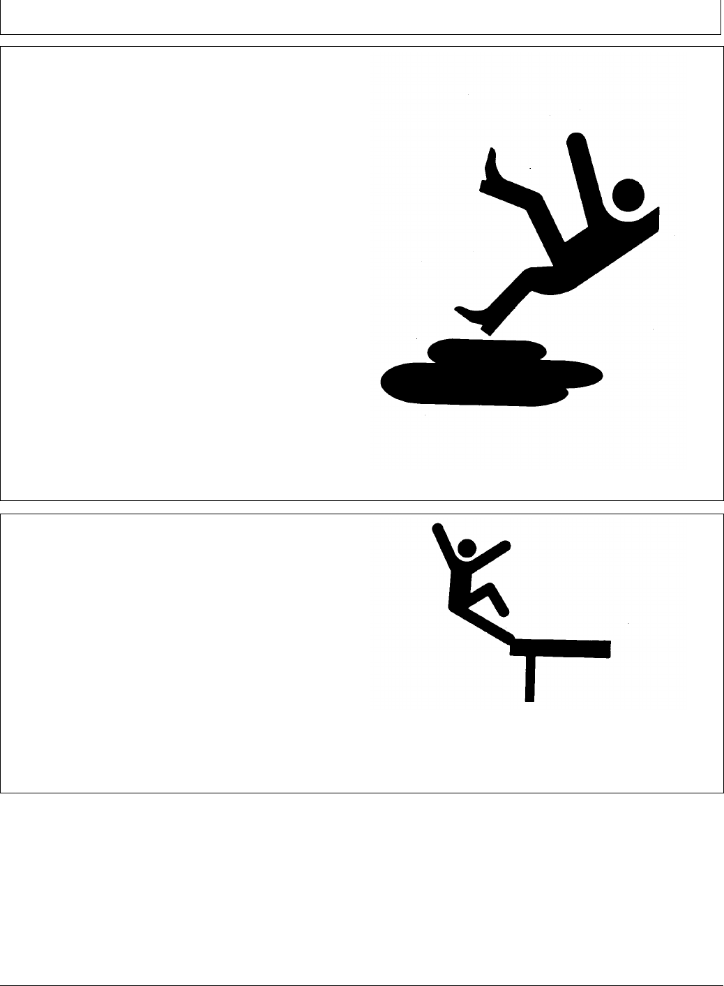
Follow Safety Instructions
Carefully read all safety messages in this manual and on
your machine safety signs. Keep safety signs in good
condition. Replace missing or damaged safety signs. Be
sure new equipment components and repair parts include
the current safety signs. Replacement safety signs are
available from your John Deere dealer.
There can be additional safety information contained on
parts and components sourced from suppliers that is not
reproduced in this operator's manual.
Learn how to operate the machine and how to use controls
properly. Do not let anyone operate without instruction.
Keep your machine in proper working condition.
Unauthorized modications to the machine may impair the
function and/or safety and affect machine life.
TS201 —UN—23AUG88
If you do not understand any part of this manual and need
assistance, contact your John Deere dealer.
05-1 090811
PN=5
Safety
DX,SERV -19-17FEB99-1/1
DX,WW,RECEIVER -19-24AUG10-1/1
Practice Safe Maintenance
Understand service procedure before doing work. Keep
area clean and dry.
Never lubricate, service, or adjust machine while it is
moving. Keep hands, feet , and clothing from power-driven
parts. Disengage all power and operate controls to relieve
pressure. Lower equipment to the ground. Stop the
engine. Remove the key. Allow machine to cool.
Securely support any machine elements that must be
raised for service work.
Keep all parts in good condition and properly installed.
Fix damage immediately. Replace worn or broken parts.
Remove any buildup of grease, oil, or debris.
On self-propelled equipment, disconnect battery ground
cable (-) before making adjustments on electrical systems
or welding on machine.
On towed implements, disconnect wiring harnesses from
tractor before servicing electrical system components or
welding on machine.
TS218 —UN—23AUG88
Handle Electronic Components and Brackets
Safely
Falling while installing or removing electronic components
mounted on equipment can cause serious injury. Use a
ladder or platform to easily reach each mounting location.
Use sturdy and secure footholds and handholds. Do not
install or remove components in wet or icy conditions.
If installing or servicing a RTK base station on a tower or
other tall structure, use a certied climber.
If installing or servicing a global positioning receiver mast
used on an implement, use proper lifting techniques and
wear proper protective equipment. The mast is heavy and
can be awkward to handle. Two people are required when
mounting locations are not accessible from the ground
or from a service platform.
TS249 —UN—23AUG88
05-2 090811
PN=6

Safety
DX,ROPS1 -19-29OCT07-1/1
JS56696,0000970 -19-10MAY11-1/1
JS56696,0000615 -19-14JUN11-1/1
Use Seat Belt Properly
Use a seat belt when you operate with a roll-over
protective structure (ROPS) or cab to minimize chance of
injury from an accident such as an overturn.
Do not use a seat belt if operating without a ROPS or cab.
Replace entire seat belt if mounting hardware, buckle,
belt, or retractor show signs of damage.
Inspect seat belt and mounting hardware at least
once a year. Look for signs of loose hardware or belt
damage, such as cuts, fraying, extreme or unusual wear,
discoloration, or abrasion. Replace only with replacement
parts approved for your machine. See your John Deere
dealer.
TS205 —UN—23AUG88
Operate Guidance Systems Safely
Do not use guidance systems on roadways. Always turn
off (disable) guidance systems before entering a roadway.
Do not attempt to turn on (activate) a guidance system
while transporting on a roadway.
Guidance systems are intended to aid the operator in
performing eld operations more efciently. The operator
is always responsible for the machine path.
Guidance Systems include any application that automates
vehicle steering. This includes, but may not be limited to,
AutoTrac, iGuide, iTEC Pro, ATU, and RowSense.
To prevent injury to the operator and bystanders:
•Never get on or off a moving vehicle.
•Verify the machine, implement, and guidance system
are set up correctly. If using iTEC Pro, verify accurate
boundaries have been dened.
•Remain alert and pay attention to the surrounding
environment.
•Take control of the steering wheel, when necessary, to
avoid eld hazards, bystanders, equipment, or other
obstacles.
•Stop operation if poor visibility conditions impair your
ability to operate the machine or identify people or
obstacles in the machine path.
•Consider eld conditions, visibility, and vehicle
conguration when selecting vehicle speed.
Use AutoTrac Controller on Approved Vehicles
Use AutoTrac Controller only on Approved Vehicles—see
StellarSupport.Deere.com for list of approved vehicles
When activity monitor is selected, AutoTrac Controller
looks for operator activity every seven minutes. Operator
will receive a time-out warning 15 seconds before
AutoTrac deactivates. Pressing the resume will reset
activity monitor timer.
05-3 090811
PN=7
Safety Signs
JS56696,0000A3B -19-14JUN11-1/1
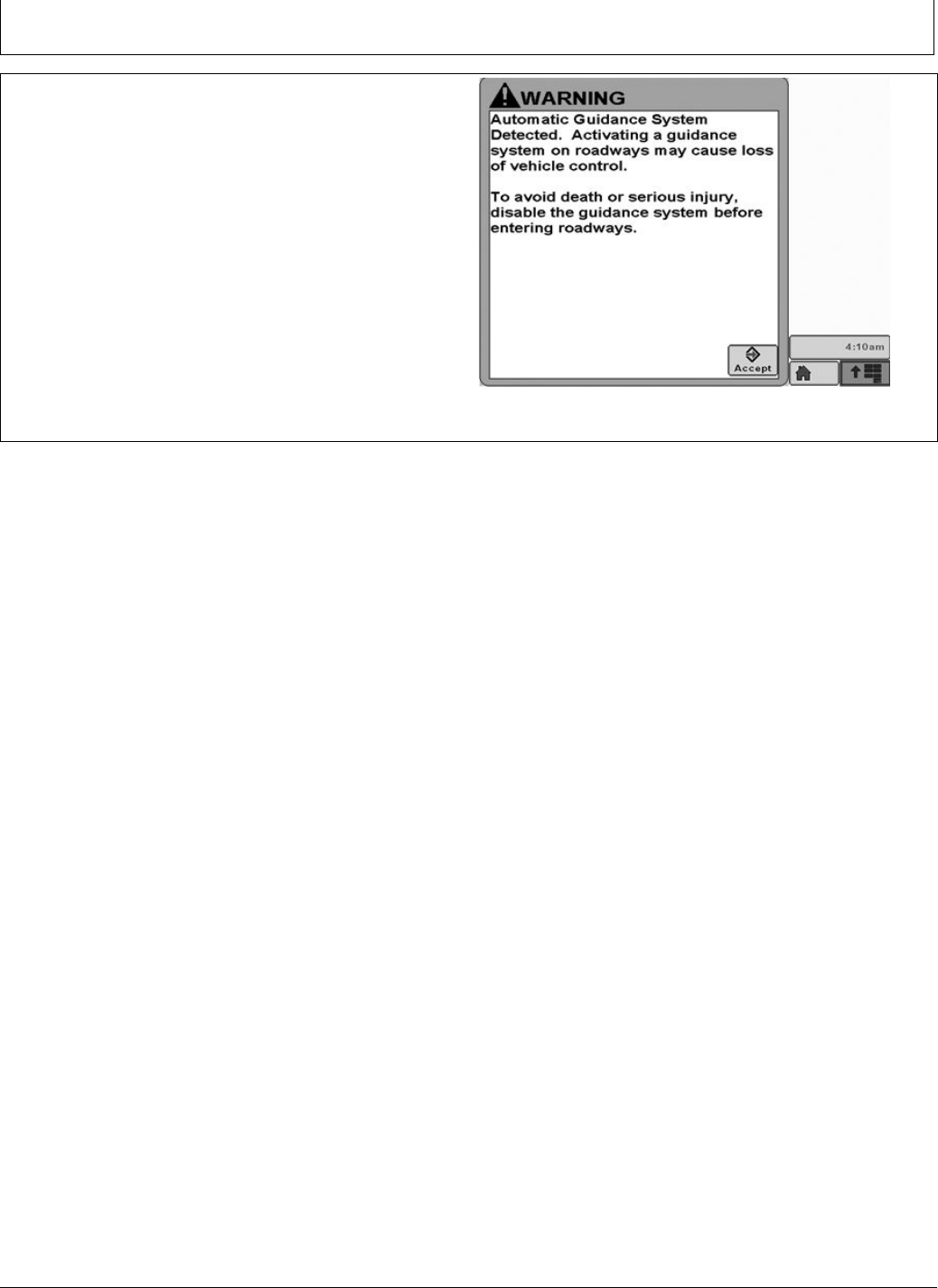
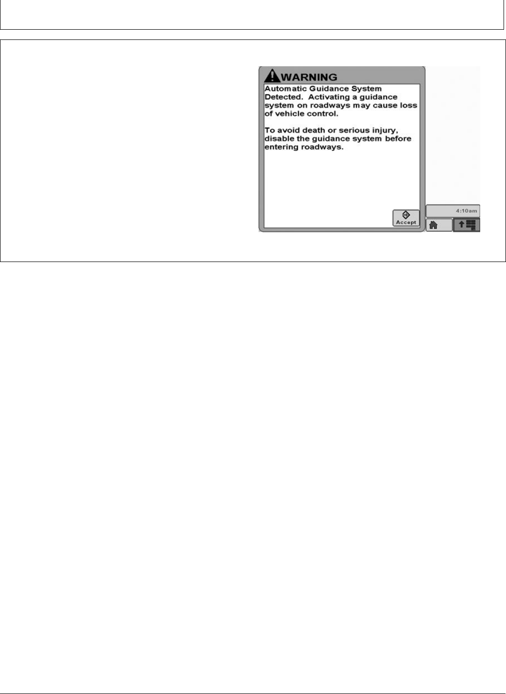
Automatic Guidance System Detected
This message occurs during startup on vehicles with
AutoTrac installed.
The master switch removes power from the EH Valve to
prevent AutoTrac from being unintentionally activated. The
master switch is intended for use on roadways or when
the operator does not want AutoTrac able to be activated.
Ensure AutoTrac is disabled by turning the Master Switch
to the OFF position.
PC13157 —19—17FEB11
Automatic Guidance
10-1 090811
PN=8

AutoTrac Controller
CF86321,00002B7 -19-05AUG11-1/1
CF86321,00002B8 -19-17MAY11-1/1
AutoTrac Accuracy
IMPORTANT: The John Deere AutoTrac system relies
on the GPS system operated by the government
of the United States, which is solely responsible
for its accuracy and maintenance. The system
is subject to changes that could affect accuracy
and performance of all GPS equipment.
The overall AutoTrac system accuracy is dependent upon
many variables. The equation looks like:
AutoTrac System Accuracy = Signal accuracy + Vehicle
Setup + Implement Setup + Field/Soil Conditions.
It is very important to remember:
•Receiver has to go through a warm-up period after
starting.
•Vehicle is setup properly (ballasted according to vehicle
operator manual, etc.)
•Implement is setup to run properly (wear parts such
as shanks, shovels, and sweeps are in good working
condition and correctly spaced).
•Understand how eld/soil conditions affect system
(loose soil requires more steering than rm soil, but rm
soil can cause uneven draft loads).
IMPORTANT: Although AutoTrac system can be
activated when SF2 (or SF1 if using AutoTrac
SF1 activation) correction signal is conrmed,
system accuracy may continue to increase
after powering up system.
AutoTrac SF2 activation will operate on a SF1, SF2, or
RTK signal.
AutoTrac SF1 activation will operate on a SF1 signal only.
General Information
All operators must be familiar with AutoTrac system and
operating characteristics prior to operation. Operator must
know the make of the AutoTrac controller installed on their
machine prior to operation.The following is a suggested
procedure for operator to become familiar with system:
1. Read and understand Operators Manual for GreenStar
Guidance—Parallel Tracking and AutoTrac Assisted
Steering Systems.
2. Choose an open area free of hazards (ditches,
buildings, etc.).
3. Set Track Spacing to 92.0 meters (300 ft).
4. Set a Track 0 (A—B Line).
NOTE: Operate vehicle at a speed you are comfortable,
recommend less than 8 km/h (5 mph).
5. Enable AutoTrac on display by turning Steer ON.
6. Press Resume switch to activate AutoTrac. (See
Activating system later in this section).
7. After driving a short distance, then turn steering wheel
to turn vehicle off track to deactivate AutoTrac. (See
Deactivating System later in this section).
8. Practice Activating AutoTrac at different distances
before and after crossing track and at different angles.
Increase and decrease speeds to simulate different
operating conditions.
9. Reduce Track Spacing to acquire multiple tracks and
continue practicing activating AutoTrac at different
angles and varying speeds to understand how
AutoTrac behaves under different conditions.
Always be prepared to resume manual control if AutoTrac
does not perform expected maneuvers or machine course
must be changed to avoid injury or property damage.
Operator can regain manual steering by turning steering
wheel or Disabling AutoTrac by turning Steer off on
display. It is recommended practice to be as close as
possible to desired track prior to activating AutoTrac. This
will ensure correct track and direction are acquired.
The AutoTrac basic system is intended to be used as
an assistance tool to mechanical markers on planters.
Operator must evaluate overall system accuracy to
determine specic eld operations where assisted
steering may be used. This evaluation is necessary
because accuracy required for various eld operations
may differ depending on farming operation. Because
AutoTrac uses StarFire differential correction network
along with Global Positioning System (GPS), slight shifts
in position may occur over time.
To operate AutoTrac operator must set track 0 (similar to
parallel tracking) and all tracks are drawn parallel to track
0 using track spacing.
The AutoTrac system operating status can exist at four
levels: INSTALLED, CONFIGURED, ENABLED, and
ACTIVATED.
After enabling AutoTrac (see Enabling AutoTrac),
AutoTrac is activated by pressing resume switch
on armrest (see Activating AutoTrac). To return to
manual steering, operator must deactivate system (see
Deactivating System).
If required track can be shifted left, right or centered using
shift track feature on display. (See Shift Track).
15-1 090811
PN=9
AutoTrac Controller
CF86321,00002B9 -19-17MAY11-1/1
BA31779,0000232 -19-20JUL11-1/1
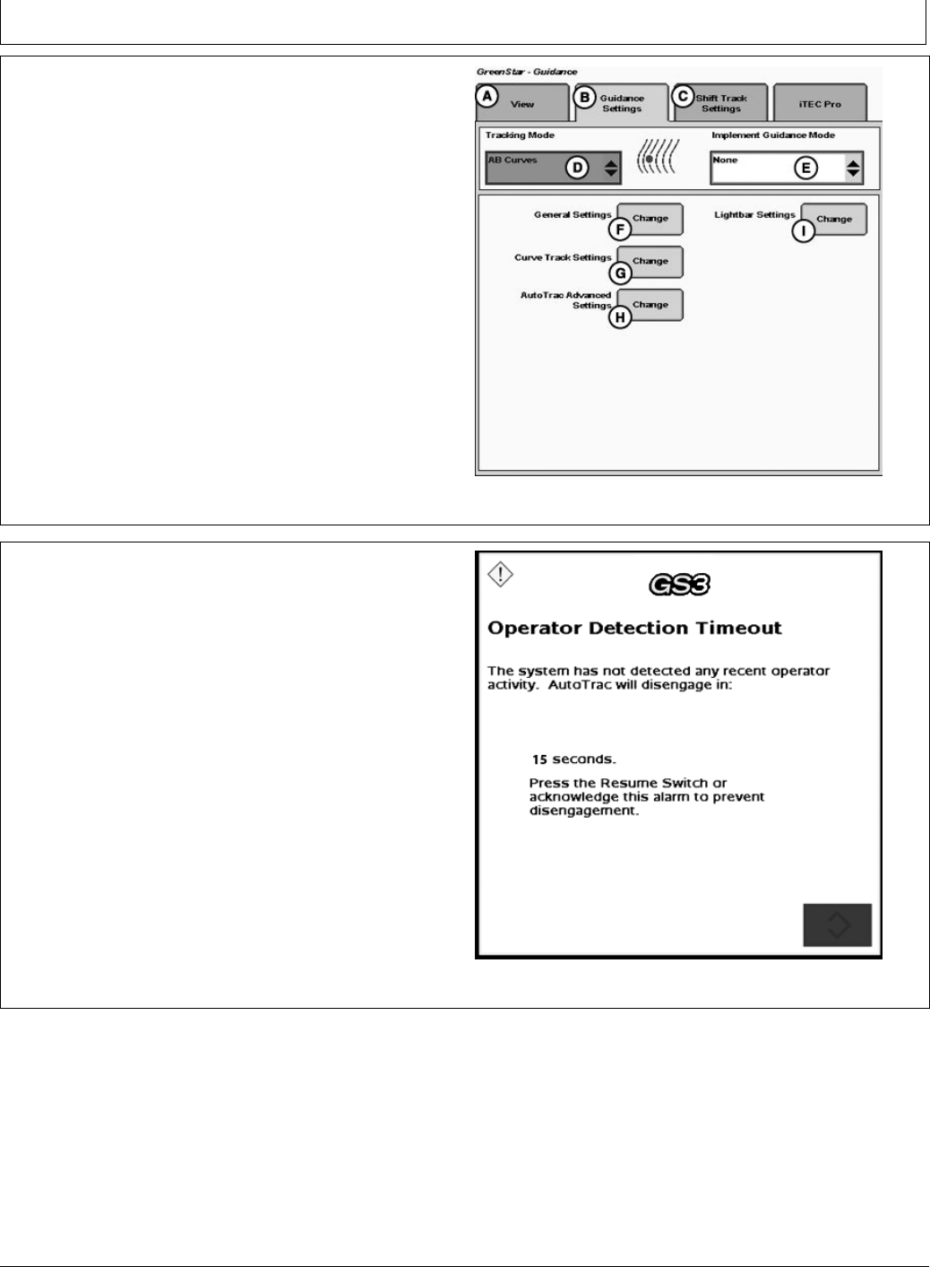
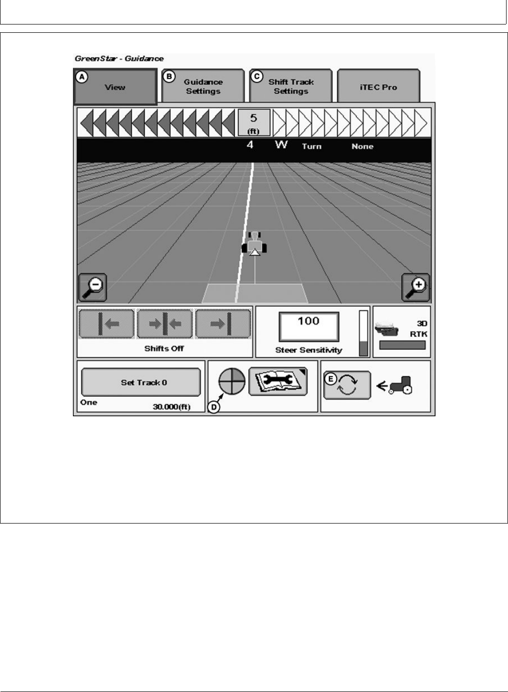
AutoTrac Settings
A—View Tab
B—Guidance Settings Tab
C—Shift Track Settings
D—Tracking Mode
E—Implement Guidance Mode
F— General Settings
G—Curve Track Settings
H—AutoTrac Advanced
Settings
I— Lightbar Settings
PC13709 —UN—13MAY11
Guidance Settings
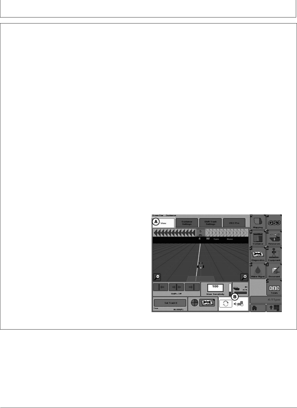
Activity Monitor
NOTE: Activity Monitor will only operate if the seat switch
is not operational or not installed on the machine.
Operator Detection Timeout
The system has not detected any recent operator activity.
AutoTrac will deactivate in: 15 seconds.
Press the Resume Switch or acknowledge this alarm to
prevent deactivation.
The Activity Monitor will monitor the status of the operator
by requiring the operator to provide input to the display
every 7 minutes.
To reset the Activity Monitor, push the resume switch or
click the Enter button on the pop-up screen.
PC13872 —UN—20JUL11
Operator Detection Timeout
15-2 090811
PN=10
AutoTrac Controller Troubleshooting
CF86321,000035D -19-23MAY11-1/1
AutoTrac Controller
Symptom Problem Solution
AutoTrac Controller won’t activate.
AutoTrac will not resume.
Stop Code encountered See list of stop codes to nd issue
AutoTrac Controller does not
appear on INFO or SETUP screens
System not recognizing AutoTrac
Controller on CAN bus line
Ensure AutoTrac Controller is
connected to GreenStar Harness and
receiving power
Check for blown fuses in AutoTrac
Controller wiring harness
Direction can not be determined Old TCM Software Update TCM Software to newest
software (Version 1.08 or greater)
No differential Correction Establish differential correction
No GPS Establish signal
AutoTrac Controller did not establish
direction correctly
Drive forward at a speed greater than
1.6 km/h (1 mph) and turn steering
wheel greater than 45 degrees in one
direction
Tractor acquires guidance line but
tracks 25 to 518 cm (10 to 204 in.)
to right or left of line.
AutoTrac Controller has encountered
a bad wheel angle sensor calibration
and has an incorrect wheel angle
sensor bias.
Recalibrate wheel angle sensor and
reacquire line to ensure problem is
corrected.
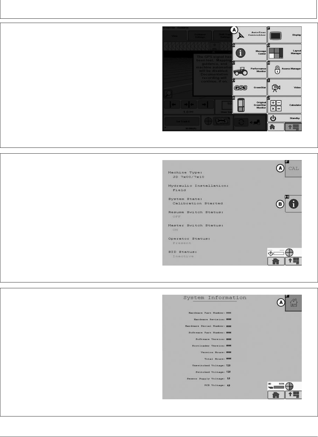
Direction Change Toggle
If the direction of travel is determined to be incorrect, Select
the View Tab (A) then select Direction Change Toggle
Button (B) to change the displayed direction of travel.
A—View Tab B—Direction Change Toggle
Button
PC13566 —UN—04MAY11
Home Screen
20-1 090811
PN=11
AutoTrac Controller Troubleshooting
CF86321,000035E -19-28JUN11-1/1
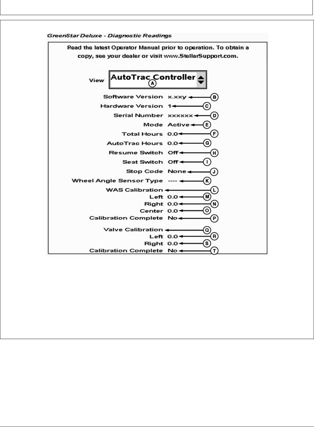
Diagnostic Readings
PC13826 —UN—28JUN11
GreenStar Diagnostic Readings
A—View Drop-Down Menu
B—Software Version
C—Hardware Part Number
D—Serial Number
E—Mode Status
F— Total Hours
G—AutoTrac Hours
H—Resume Switch Status
I— Seat Switch Status
J— Stop Code
K—Wheel Angle Sensor Type
L— WAS Calibration
M—Left WAS Calibration Number
N—Right WAS Calibration
Number
O—Center WAS Calibration
Number
P—WAS Calibration Complete
Status
Q—Valve Calibration
R—Left Valve Calibration Number
S—Right Valve Calibration
Number
T— Valve Calibration Complete
Status
Read the latest Operator Manual prior to operation.
To obtain a copy, see your dealer or visit
www.StellarSupport.com.
20-2 090811
PN=12

AutoTrac Controller Troubleshooting
CF86321,000035F -19-28JUN11-1/1
Stop Codes
Stop Code Description Solution
None Nothing has been checked yet
Steering Wheel Steering wheel has moved to deactivate AutoTrac Press resume switch to re-activate
AutoTrac
Too Slow Vehicle speed too slow to use AutoTrac Increase speed over 0.5 km/h (0.3 mph)
Too Fast Vehicle Speed too high to use AutoTrac Reduce Speed below platform limit
Tractor - 30 km/h (18.6 mph)
Sprayer - 37 km/h (23 mph)
Harvester - 22 km/h (13.7 mph)
Reverse speed on all machines – 10 km/h
(6 mph)
Unknown Direction Unknown direction Drive forward greater than 1.6 km/h (1
mph) and turn steering wheel greater than
45°
Track Changed Track number changed Align vehicle on desired track and press
resume
Lost Dual GPS SF1, SF2, or RTK signal was lost Establish signal
Steer Control Fault A steering control fault severe enough to disable
AutoTrac
Cycle tractor power
OK Last state upgrade was successful
PT Turned Off Tracking not turned on. Turn tracking on in Setup - Tracking
Heading Error Heading error is out of range. Align tractor within heading limit (80° of
track)
Lateral Error Lateral error is out of range. Align tractor within lateral limit (40% of
track spacing)
No Operator Operator presence switch is open. Operator in seat or press resume for
activity monitor to reset time
No TCM Either no TCM present or TCM is turned off. Turn TCM on, or install TCM
Voltage Unstable Voltage Too Low Check harnessing
Reverse Timeout Reverse Timeout (greater than 45 seconds) Cycle direction forward before resuming
in reverse
0 Speed Timeout 0 Speed Timeout Increase speed over 0.5 km/h (0.3 mph)
Curvature Curve Track radius tighter than AutoTrac will allow Manually drive through tight radius curves
Tracking on Line Vehicle is driving on line
Acquiring Line Vehicle is acquiring line
20-3 090811
PN=13
AutoTrac Controller—Raven
BA31779,0000223 -19-04AUG11-1/21
BA31779,0000223 -19-04AUG11-2/21
Continued on next page BA31779,0000223 -19-04AUG11-3/21
AutoTrac Controller— Raven Calibration
IMPORTANT: John Deere 2600 Display will not operate
with AutoTrac Controller—Raven™
NOTE: Calibration procedure must be completed with a
passing status prior to using AutoTrac.
From the Main Menu select AutoTrac Controller.
A—AutoTrac Controller
PC13382 —UN—20JUL11
AutoTrac Button
AutoTrac Main Screen will appear.
In the AutoTrac main screen select the CAL button (A).
The Calibration Assistant main screen will appear.
A—Calibration Button B—Information Button
PC13383 —UN—20APR11
AutoTrac Main Screen
Select the System Information button (B). This will display
information to inform the operator that AutoTrac is ready
for calibration. Some information is software version and
operating voltages. If there are no voltages make sure to
check all connections.
After all information is veried select the AutoTrac home
button (A) in the upper right of the screen. This will
navigate back to the AutoTrac main screen.
A—Home Button
PC13384 —UN—19MAY11
System Information
25-1 090811
PN=14
AutoTrac Controller—Raven
BA31779,0000223 -19-04AUG11-4/21
Continued on next page BA31779,0000223 -19-04AUG11-5/21
IMPORTANT: Read all instructions before calibrating
the AutoTrac Controller
AutoTrac calibration should completed without
an implement connected to the tractor to avoid
damage to the tractor or implement.
•Drive tractor slowly at full throttle for approximately
2 to 5 minutes to bring hydraulic uid to operating
temperature before beginning calibration procedure.
•Calibration procedure will require a large, open, level
surface to complete the required steps.
•Calibration procedure must be completed prior to using
AutoTrac for the rst time.
•Calibration procedure must be complete with a passing
status prior to using AutoTrac. If a passing status is not
achieved then AutoTrac will not work.
NOTE: At any time during calibration, the operator
may take control of the system by grabbing the
steering wheel or stopping the machine.
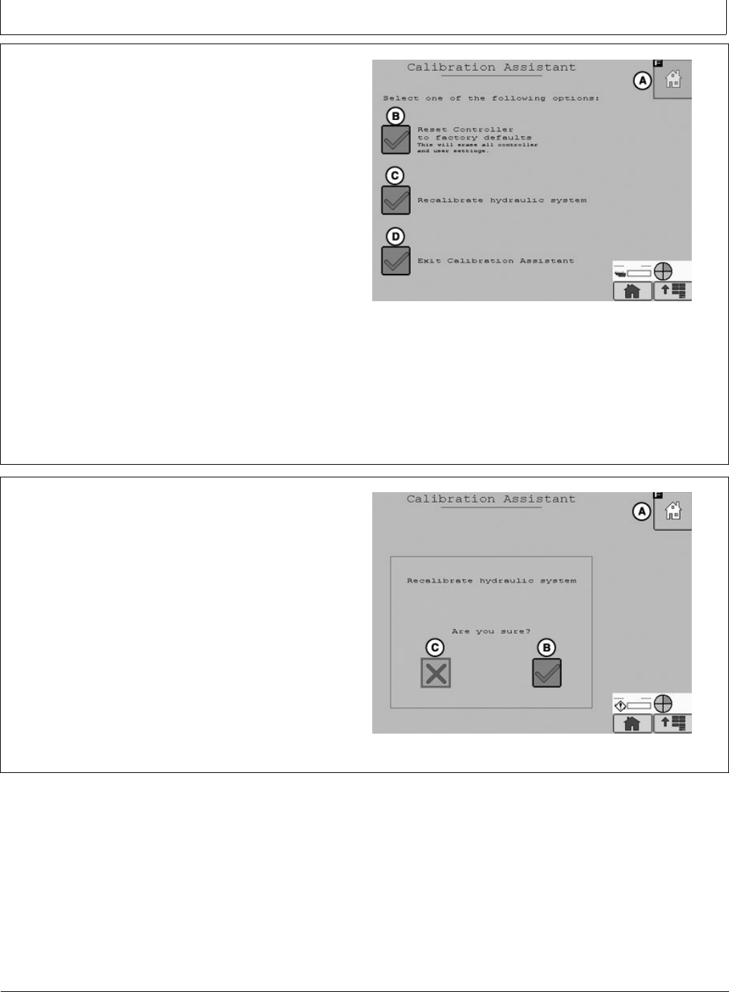
To begin calibration select Recalibrate Hydraulic System
button (C) form the Calibration Assistant Main screen.
PC13385 —UN—20APR11
Calibration Assistant Main Screen
A—Home
B—Reset controller to Factory
Defaults
C—Recalibrate Hydraulic
System
D—Exit Calibration Assistant
To proceed with the calibration process select yes (B) to
proceed or select no (C) to cancel.
A—Home
B—Yes
C—No
PC13387 —UN—20APR11
Recalibrate Hydraulic System
25-2 090811
PN=15
AutoTrac Controller—Raven
BA31779,0000223 -19-04AUG11-6/21
BA31779,0000223 -19-04AUG11-7/21
Continued on next page BA31779,0000223 -19-04AUG11-8/21
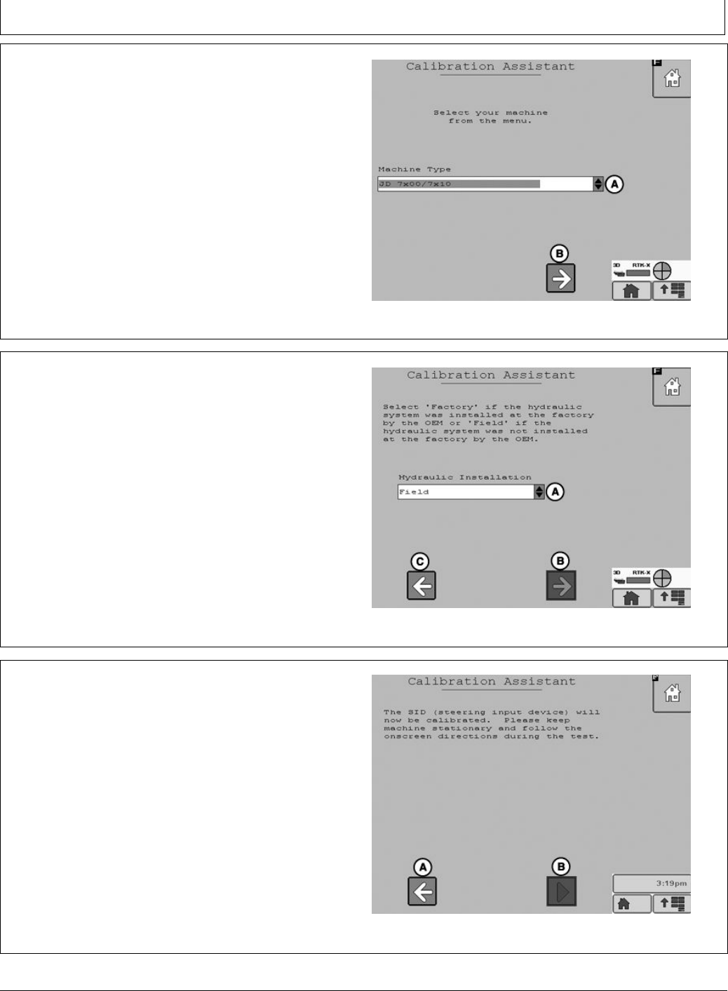
Select the machine type from the drop down menu (A)
then select the Next Button (B).
A—Drop Down Menu B—Next
PC13388 —UN—20APR11
Machine Type
Select Kit type from the drop down menu (A). If the Kit was
installed by the factory select Factory, if it was not installed
at the factory select Field. Select Next (B) to proceed,
select previous (C) to return to the Machine Type screen.
A—Drop Down Menu
B—Next
C—Previous
PC13389 —UN—20APR11
Kit Type
Select Start (B) to calibrate the SID (steering input device).
Select Previous to return to the Kit Type screen.
A—Previous B—Start
PC13390 —UN—28JUL11
SID Calibration
25-3 090811
PN=16
AutoTrac Controller—Raven
BA31779,0000223 -19-04AUG11-9/21
BA31779,0000223 -19-04AUG11-10/21
Continued on next page BA31779,0000223 -19-04AUG11-11/21
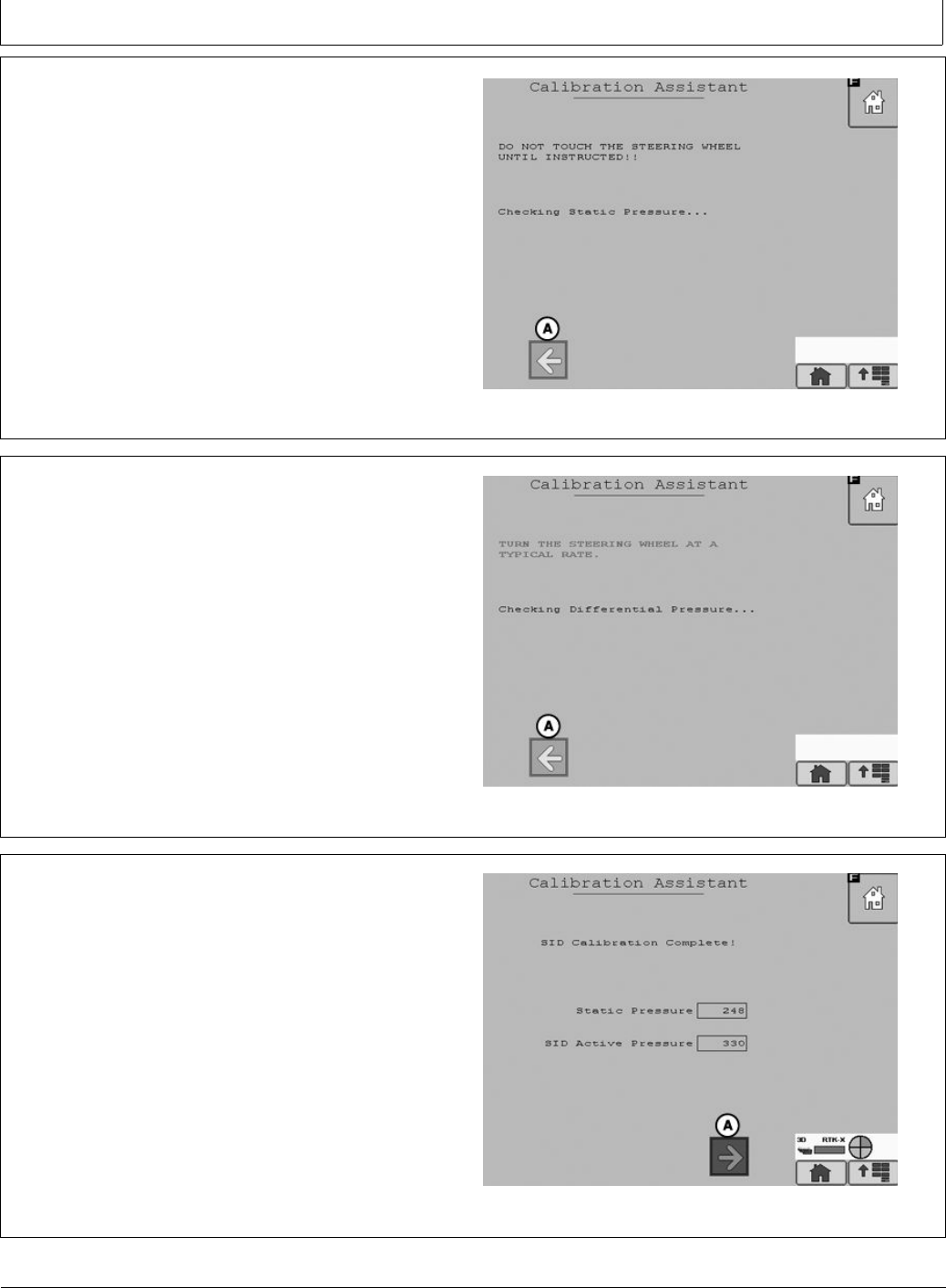
SID will start calibration. Do not touch the steering wheel
until instructed. AutoTrac will perform a static pressure
test .
A—Previous
PC13391 —UN—20APR11
SID Calibration
When instructed turn the steering wheel at a normal rate.
AutoTrac will perform a Active Pressure test.
NOTE: Turning the steering wheel too fast or too slow
will cause an inaccurate calibration and may cause
undesired AutoTrac performance.
PC13394 —UN—20APR11
Differential Pressure Test
When the Active pressure test is complete the SID
Calibration Complete screen will appear. Select Next (A)
to proceed to the Resume Switch Status screen.
A—Next
PC13395 —UN—20APR11
SID Calibration Complete
25-4 090811
PN=17
AutoTrac Controller—Raven
BA31779,0000223 -19-04AUG11-12/21
BA31779,0000223 -19-04AUG11-13/21
Continued on next page BA31779,0000223 -19-04AUG11-14/21
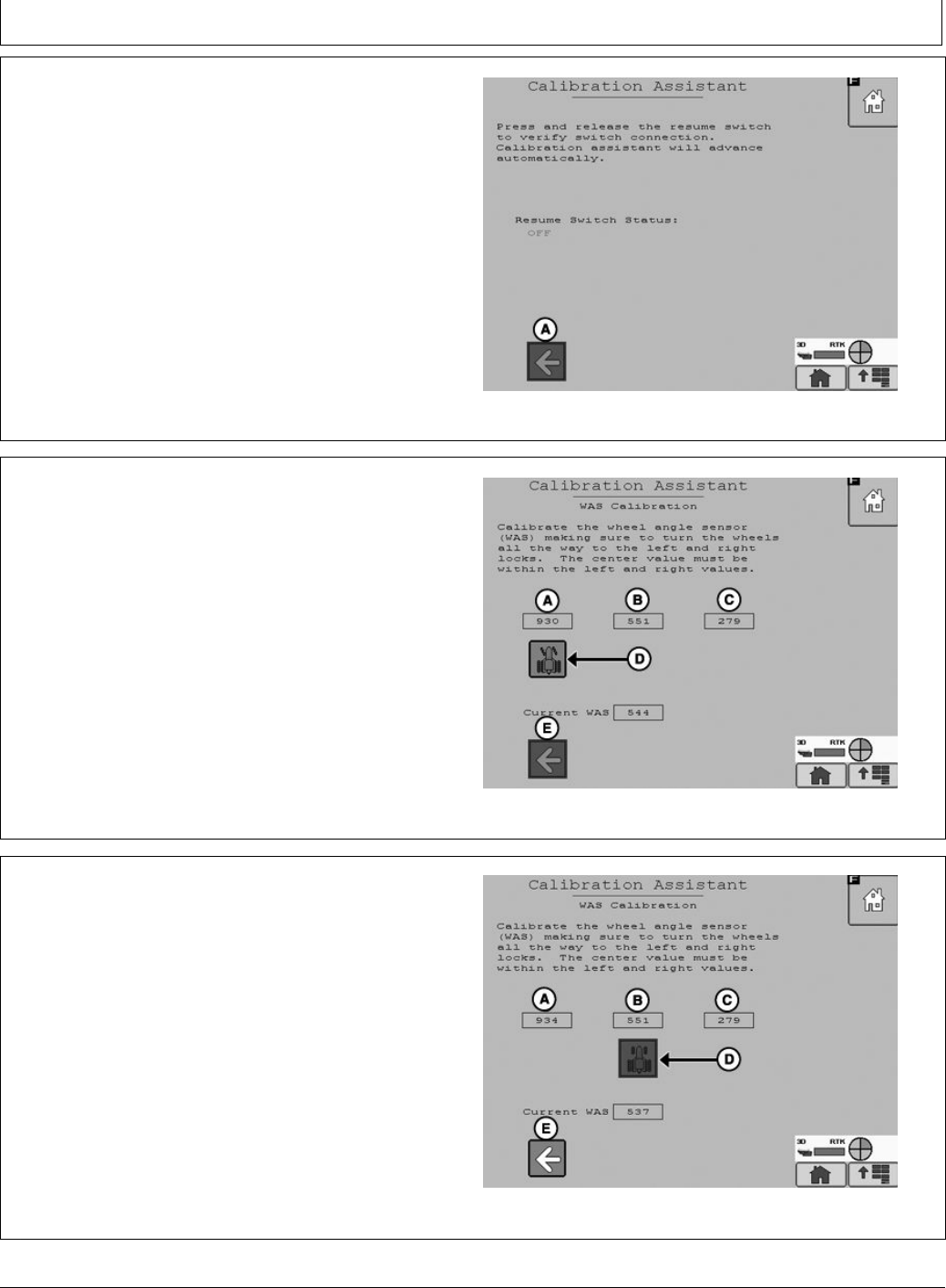
Press and release the resume switch. The red “OFF” text
will change to green “ON” text when the button is pressed
and back to red “OFF” text when the button is released.
When successful the screen will change to the WAS
(Wheel Angle Sensor) Calibration screen.
Select previous to return to SID calibration.
A—Previous
PC13396 —UN—20APR11
Resume Switch Status
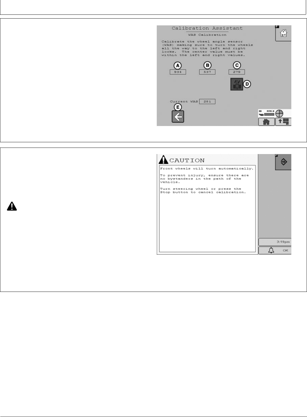
NOTE: It is important that the wheels are turned all of the
way to the left and right during the WAS Calibration
or undesired AutoTrac operation may occur.
Turn the steering wheel left all the way to the wheels stops
and select the tractor icon (D). Selecting the tractor icon
will make the icon move under the WAS Center Value (B).
A—WAS Left Value
B—WAS Center Value
C—WAS Right Value
D—Tractor Icon
E—Previous
PC13397 —UN—20APR11
WAS Calibration Left
NOTE: An accurate center WAS calibration is critical to
have desired AutoTrac operation. Driving a short
distance looking down the center of the hood and
turning your wheels so that you drive straight to a
xed point on the horizon maybe required.
Turn the steering wheel so the wheels are pointing straight
forward and select the tractor icon (D). Selecting the
tractor icon will make the icon move under the WAS Right
Value (C). Selecting previous will make the tractor icon
move under the WAS Left Value (A) allowing the operator
to change the WAS Left Value.
A—WAS Left Value
B—WAS Center Value
C—WAS Right Value
D—Tractor Icon
E—Previous
PC13398 —UN—20APR11
WAS Calibration Center
25-5 090811
PN=18
AutoTrac Controller—Raven
BA31779,0000223 -19-04AUG11-15/21
Continued on next page BA31779,0000223 -19-04AUG11-16/21
Turn the steering wheel all the way to the right wheel stops
and select the tractor icon (D). Selecting the tractor icon
will complete the WAS Calibration process and navigate
to the Valve Autocalibration screen.
Selecting Previous will make the tractor icon move under
the WAS Center Value (B) allowing the operator to change
the WAS Center Value.
NOTE: The WAS Center Value must be between the
WAS Left Value and the WAS Right Value for
the WAS Calibration to be valid.
A—WAS Left Value
B—WAS Center Value
C—WAS Right Value
D—Tractor Icon
E—Previous
PC13399 —UN—20APR11
WAS Calibration Right
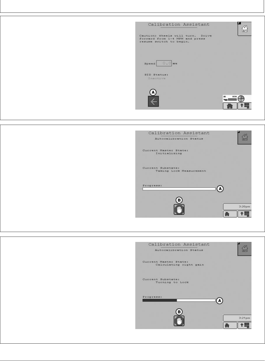
Front wheels will turn automatically.
To prevent injury, ensure there are no bystanders in the
path of the vehicle.
Turn steering wheel or press the Stop button to cancel
calibration.
CAUTION: Calibration procedure will require
a large, open, level surface to complete
the required steps.
Check for bystanders or obstacles before starting
the autocalibration process. Failure to do so
may cause injury to yourself, or others. Severe
damage to the machine could also occur.
NOTE: You can abort the autocalibration procedure and
take over control at any time by manually turning
the steering wheel. This will result in a failed
calibration. When you restart the autocalibration
it will begin where it left off.
PC13874 —UN—28JUL11
25-6 090811
PN=19
AutoTrac Controller—Raven
BA31779,0000223 -19-04AUG11-17/21
BA31779,0000223 -19-04AUG11-18/21
Continued on next page BA31779,0000223 -19-04AUG11-19/21
To start the Valve autocalibration process the machine
must be moving forward at 1 to 4 mph. When the machine
is moving at 1 to 4 mph press the resume switch to start
the autocalibration process.
Select previous (A) to navigate back to WAS Calibration.
A—Previous
PC13400 —UN—20APR11
The autocalibration screen will display when the resume
button is pressed. The progress bar (A) will start to ll
during the autocalibration process.
To stop autocalibration select Stop (B) at any time. The
operator can also turn the steering wheel at anytime to stop
autocalibration. If the autocalibration is stopped at any
time it must be completed before AutoTrac will operate.
NOTE: Do not turn the steering wheel during the
autocalibration process unless it is an emergency.
Turning the steering wheel will cause the test to
stop. If the test is stopped it must be completed
before AutoTrac will operate.
A—Progress Bar B—Stop
PC13401 —UN—28JUL11
Autocalibration Status
Autocalibration process will go through several steps. The
last step is calculating right min. The Progress bar will ll
completely indicating the autocalibration is nished.
A—Progress Bar
PC13402 —UN—28JUL11
Calculating right min
25-7 090811
PN=20
AutoTrac Controller—Raven
BA31779,0000223 -19-04AUG11-20/21
BA31779,0000223 -19-04AUG11-21/21
CF86321,0000337 -19-23MAY11-1/1
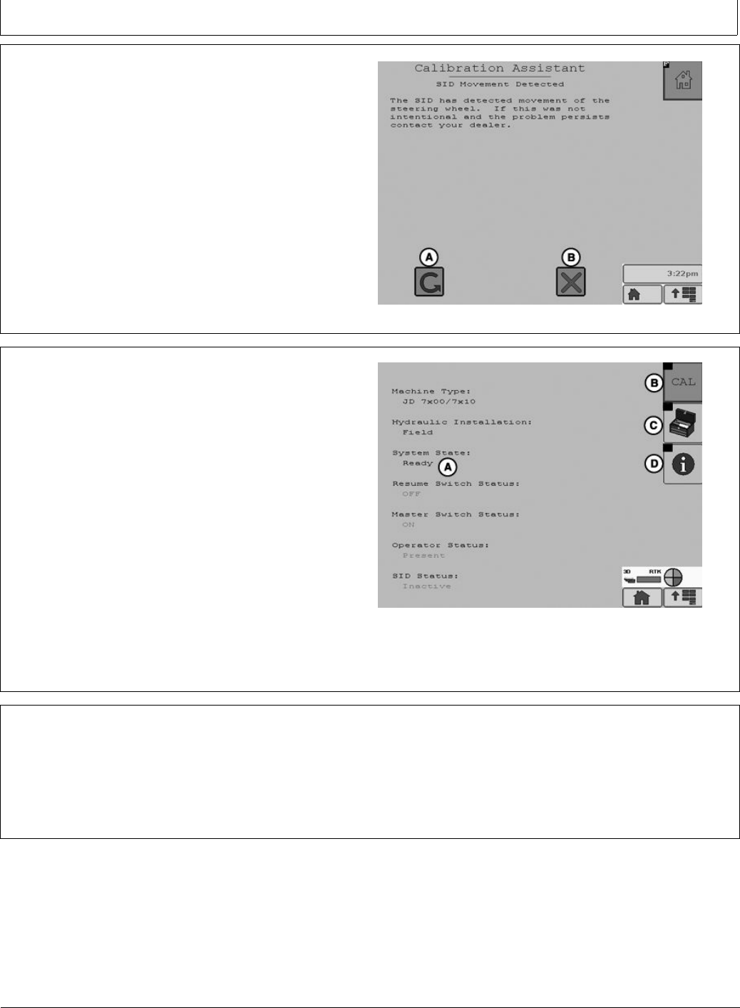
During the valve calibration if the Stop button is pressed
or the steering wheel is moved the user is given the option
to continue (A) the calibration or cancel (B).
A—Continue B—Cancel
PC13964 —UN—03AUG11
When autocalibration is complete the main screen will
appear. If the calibration completed successfully then
system state (A) will read “READY”. If the calibration
failed system state (A) will read “FAULT”. If calibration
failed select CAL (B) to start the calibration process over.
If the calibration process was aborted or not completed
the system state (A) will read “Calibration Started”.
If the calibration is successful then the Tool Box (C) will
appear on the screen. Tool Box gives access to vehicle
health test.
NOTE: Vehicle health test should only be completed
by a dealer.
Selecting system information (D) will display information
about the AutoTrac system.
A—System State Ready
B—CAL
C—Tool Box
D—Information
PC13403 —UN—20APR11
System State
Failed Calibrations
If calibration failure persists, check the Message Center
and/or contact your John Deere dealer.
A failed calibration may be the result of:
•Incorrect inputs provided by the operator
•Not enough area to complete calibration without
stopping during the calibration step
•Grabbing the steering wheel to avoid obstacles
•Wheel angle sensor not responding
•Valve not responding.
•Machine hardware failure
25-8 090811
PN=21
AutoTrac Controller—Raven
CF86321,0000338 -19-23MAY11-1/2
CF86321,0000338 -19-23MAY11-2/2
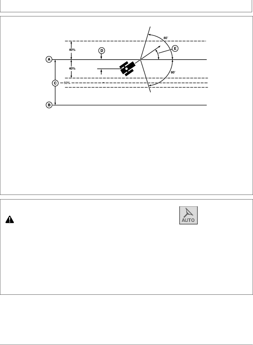
Necessary Conditions for Activating
AutoTrac
80˚
80˚
40%
40%
Track
Spacing
Track No. 0
Off-Track
Lateral Error
Track No. changes at 50%
Track Heading
Error
Track No. 1-S
PC7051 —19—04FEB02
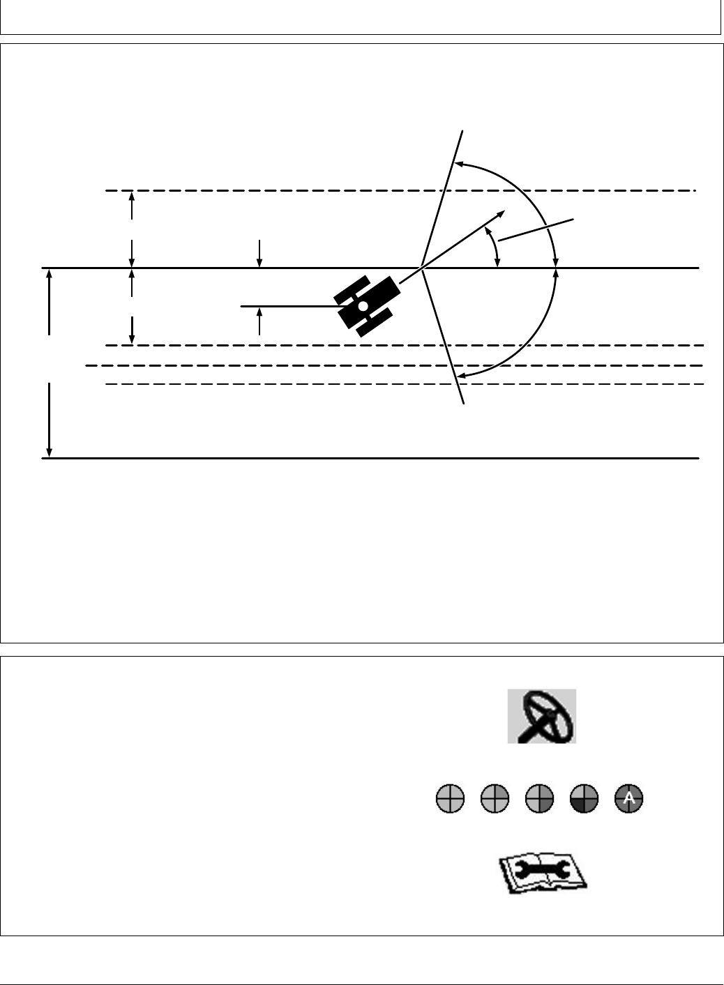
Once tractor is at end of row operator must turn system
to next pass. By turning steering wheel, AutoTrac is
deactivated. Operator must turn onto next track.
AutoTrac can be activated by pressing resume switch only
after following conditions are met:
NOTE: Calibration procedure must be complete with a
passing status prior to using AutoTrac.
1. System is enabled (steering ON on RUN screen).
2. The machine is within 40% of track spacing.
3. Track heading is within 80° of track.
Once two pieces of the PIE are achieved, the operator
can enable AutoTrac by selecting the Steer On icon.
If two pieces of the PIE can not be achieved, the operator
will not be able to activate AutoTrac.
•A diagnostic button is located next to the PIE icon.
•If two pieces of the PIE can not be achieved, select
wrench icon to view AutoTrac Diagnostics.
The Diagnostics page will indicate what is needed for each
of the four PIE pieces and the status of all requirements.
AutoTrac may not become available until hydraulic
temperature has reached pre set level (1 PIE piece only
until warm). This issue will not provide any diagnostic
code or show in the status menu.
PC11972 —UN—09APR09
Steer On icon
PC11971 —UN—09APR09
Pie Pieces
PC11973 —UN—09APR09
AutoTrac Diagnostics Wrench
25-9 090811
PN=22
AutoTrac Controller—Raven
Continued on next page CF86321,0000339 -19-28JUN11-1/2
AutoTrac Controller—Raven Diagnostic
Addresses
Diagnostic Adresses
Select Diagnostic Address button and a list of controllers
will appear and controllers with diagnostic codes are
indicated.
Individual controllers can be accessed by pressing
ENTER button to view codes for that controller.
To view the AutoTrac Controller Raven select ACI.001
Implement form the device drop down menu.
Codes can also be displayed for all controllers by
selecting SHOW ALL button and pressing ENTER button.
Codes can be relayed to a John Deere dealer to assist in
diagnosing machine problems.
All diagnostic codes below are specic to AutoTrac
Controller—Raven.
PC8663 —UN—05AUG05
MENU button
PC8655 —UN—05AUG05
MESSAGE CENTER button (With Info Icon)
PC8668 —UN—05AUG05
Diagnostic Addresses
Diagnostic Address Description
001 Recall Trouble Codes
003 ELX Voltage
004 Battery voltage
005 5V Regulator Voltage at the Regulator
008 LS pressure Sensor Voltage
009 LS Pressure Sensor-Measured pressure in kpa
010 WAS/Gyro Sensor Voltage
013 WAS Calibrated Center Voltage
014 WAS Calibrated Full-Left Voltage
015 WAS Calibrated Full-Right Voltage
016 WAS Actual Wheel Angle
019 GPS Speed kph
023 Max Flow Rate Test
025 Closed-loop Step Response Test
031 Adjustable Parameter-Heading Lead
037 AutoTrac Aggressiveness
048 Adjustable Parameter-Inner-Loop Gain
051 Adjustable Parameter-Heading Gain
052 Adjustable Parameter-Curvature Sensitivity
053 Adjustable Parameter-Acquisition Sensitivity
054 Adjustable Parameter-Lateral Gain
056 Auto Trac Hours
060 Auto Trac Exit Code
061 Steer Switch-Resume Switch-Auto Trac State
062 Parallel Tracking-Keycard Present-TCM State
063 Seat/Track Number/GPS Status
065 Lateral Error
067 Heading Error
071 Lateral Error Accumulator
076 Engineering Diognostics Enable/Disable
25-10 090811
PN=23

AutoTrac Controller—Raven
CF86321,0000339 -19-28JUN11-2/2
Diagnostic Address Description
077 Actual Curvature
078 Target Curvature
079 Yaw-Rate
080 Inner loop Gain Proportional
081 Inner Loop Gain Integral
082 Inner Loop Gain Derivative
083 Inner Loop Filtered Constant 1
084 Inner Loop Filtered Constant 2
085 Valve Left Gain
086 Valve Right Gain
087 Valve Left Deadband (%)
088 Valve Right Deadband (%)
089 Signal to valve (%)
090 Current draw from valve (Power line) (mA)
091 Pressure Sensor 2 Voltage
092 Pressure Transducer 2 (kPa)
093 Pressure Differential (kPa)
110 Steering Override Setting - SID Disengage Pressure Setting (kPa)
112 Valve Left Gain 1
113 Valve Left Gain 2
114 Valve Left Gain 3
115 Valve Left Gain 4
116 Valve Left Gain 5
117 Valve Left Gain 6
118 Valve Left Gain 7
119 Valve Left Gain 8
120 Valve Left Gain 9
121 Valve Left Gain 10
122 Valve Right Gain 1
123 Valve Right Gain 2
124 Valve Right Gain 3
125 Valve Right Gain 4
126 Valve Right Gain 5
127 Valve Right Gain 6
128 Valve Right Gain7
129 Valve Right Gain 8
130 Valve Right Gain 9
131 Valve Right Gain 10
200 Password
219 Controller Conguration Data Part Number
220 Controller Conguration Data Version Number
25-11 090811
PN=24
AutoTrac Controller—Raven
Continued on next page CF86321,000033A -19-28JUN11-1/2
AutoTrac Controller—Raven Diagnostic
Trouble Codes
Select TROUBLE CODES button, a list of controllers will
appear and controllers with diagnostic codes are indicated.
Individual controllers can be accessed by pressing
ENTER button to view codes for that controller.
Codes can also be displayed for all controllers by
selecting SHOW ALL button and pressing ENTER button.
Codes can be relayed to a John Deere dealer to assist in
diagnosing machine problems.
PC8663 —UN—05AUG05
MENU button
PC8655 —UN—05AUG05
MESSAGE CENTER button (With Info Icon)
PC8669 —UN—05AUG05
TROUBLE CODES softkey
SPN FMI Description
168 3 Steering Controller unswitched supply voltage (cc# 182) out of range high
168 4 Steering Controller unswitched supply voltage (cc# 182) out of range low
232 9 Loss of StarFire Differential Status Message (PGN 65535/0x53)
517 9 GPS Speed Message Missing
628 12 Indicates control unit Steering Controllerbeing reprogrammed (boot block generated). Reprogram control unit Steering
Controller. Replace control unit Steering Controller if condition persists.
630 13 Indicates incomplete calibration of steering valve. Wheel Angle Sensor calibration incomplete. AutoTrac will remain disabled
until successful calibration of system.
1504 9 Operator out of seat during AutoTrac
1504 14 Operator out of seat during AutoTrac
1504 31 Operator out of seat during AutoTrac - within 2 to 7s
3509 3 Indicates sensor supply voltage (cc# 733) for steering wheel pressure sensor and/or wheel angle position sensor out
of range high.
3509 4 Indicates sensor supply voltage (cc# 733) for steering wheel pressure sensor and/or wheel angle position sensor out
of range low.
3509 5Steering Wheel Position Sensor 1 Circuit Current Low
3509 6 Steering Wheel Position Sensor 1 Circuit Current High
1807 5Steering Wheel Angle
1807 6 Steering Wheel Angle
520431 5Isolation Shutoff Valve Circuit Current Low
520431 6 Isolation Shutoff Valve Circuit Current Current High
522385 1 Indicates that the AutoTrac Controller ON/OFF switch on vehicle is not ON. Switch AutoTrac master switch to ON position.
522387 7Indicates control unit Steering Controller not receiving wheel angle position sensor signal.
522390 9 Abnormal Update Rate
522394 9 TCM Messages Missing
523698 9 IVS Display Message Missing
523767 2 AutoTrac Resume Switch Circuits Conict
523795 2 Indicates steering valve orientation incorrect. Check steering valve right/left circuit codes switched.
523795 11 Indicates steering valve deadbands inconsistent
523795 13 The deadband is out of range.
523795 12 EH Valve or harness fault
523824 5Controller - Not in FMEA
25-12 090811
PN=25

AutoTrac Controller—Raven
CF86321,000033A -19-28JUN11-2/2
SPN FMI Description
523824 6 Controller - Not in FMEA
523826 0 Wheel Angle Sensor Primary Signal High
523826 1 Wheel Angle Sensor Primary Signal Low
523826 2 Steering Controller Calibration / Wheel Angle Sensor Polarity
523826 7Wheel Angle Sensor Primary Fault/No Motion
523826 10 Wheel Angle Sensor Fault/No SID Motion
523826 14 Primary and Secondary Wheel Angle Sensor Conict
524221 9 Vehicle Yaw Rate Message Missing
25-13 090811
PN=26
GS2 Display 1800
CF86321,000038D -19-01JUN11-1/1
CF86321,000038E -19-01JUN11-1/1
CF86321,000038F -19-01JUN11-1/1
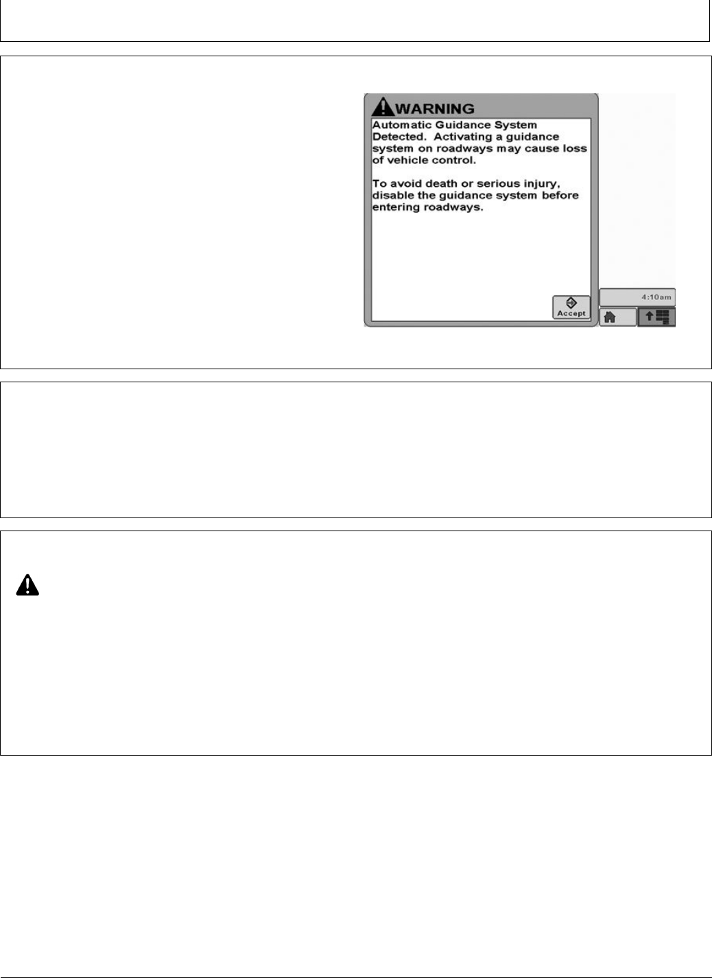
Automatic Guidance System Detected
Each time a machine equipped with AutoTrac is started,
this screen will appear as a reminder of operator
responsibilities when using AutoTrac steering system.
PC13157 —19—17FEB11
Automatic Guidance
Enabling System
Press STEER ON/OFF button to toggle between
enable/disable AutoTrac.
To enable system, all of the following criteria must be met:
•AutoTrac activation is detected.
•Track 0 has been setup.
•Tracking mode selected.
•Proper operator presence mode selected.
•TCM must be installed and turned on.
•AutoTrac Controller Steering Kit is plugged in.
Activating System
CAUTION: While AutoTrac is activated, operator
is responsible for steering at end of path
and collision avoidance.
Do not attempt to turn on (Activate) AutoTrac
system while transporting on a roadway.
After system has been ENABLED, operator must manually
change system to ACTIVATED status when steering
assistance is desired.
Press resume switch. This will initiate assisted steering.
In order to activate system following criteria must be met:
•Vehicle speed is greater than 0.5 km/h (0.3 mph).
•Forward vehicle speed is less than 30 km/h (18.6 mph)
•Reverse vehicle speed is less than 10 km/h (6.0 mph).
•Vehicle within 45 degrees of desired track.
•Operator is seated.
•TCM is on.
•In reverse AutoTrac will remain activated for 45
seconds. After 45 seconds the machine must be put in
a forward gear before reverse will activate again.
30-1 090811
PN=27
GS2 Display 1800
BA31779,000024B -19-01AUG11-1/23
Continued on next page BA31779,000024B -19-01AUG11-2/23
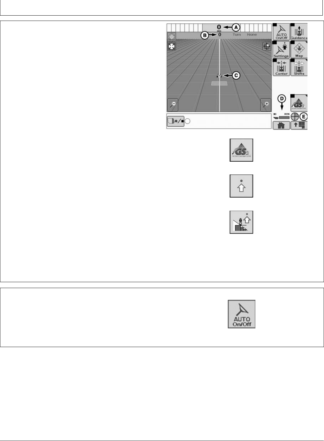
GreenStar Run Page
Path Accuracy Indicator - Is a visual indicator of off-track
error. The indicator consists of eight boxes on each side
of the off-track error box. The boxes will light up indicating
the direction the vehicle must be steered to get back on
the AB line. Each arrow represents a distance (default is
10 cm (4 in.)). This distance and the steering direction
may be dened on the Lightbar Settings Page:
GreenStar Main Page -> Settings -> Guidance Settings
-> Lightbar Settings
Off Track Error (A)– Off Track error is numerically displayed
in the box. Off Track error will be displayed in cm (inches)
up to 99 cm (35 in.). If Off Track error exceeds 99 cm (35
in.), the distance displayed will change to meters (feet).
Track number (B)– Represents the track number the
vehicle is guiding on. It also shows the direction that the
track is located from the original Track 0 for the eld.
Guidance Icon (C)– The icon represents the machine and
implement in relative dimensions. The triangle on the
machine represents the control point, which as used for
guiding the machine and is dened by the machine offset
measurements.
GPS Indicator (D)— Indicates what level of accuracy the
StarFire receiver is currently operating at (3D, SF2, SF1,
RTK). If using a GPS receiver other than a StarFire, the text
3D GPS will be displayed but the indicator bar will not ll.
AutoTrac Status Pie (E)(See AutoTrac section)
NOTE: Some softkeys only appear when the
hardware or functions associated with those
buttons are connected or available, such as
the AutoTrac controls.
PC13962 —UN—01AUG11
PC10857JN —UN—13APR09
GreenStar Main Page
PC10857JF —UN—13APR09
Settings Button
PC10857KZ —UN—14APR09
Guidance Settings
A—Off Track Error
B—Track number
C—Guidance Icon
D—GPS Indicator
E—AutoTrac Status Pie
AutoTrac Steer On/Off – Enables and disables AutoTrac PC13711 —UN—16MAY11
Auto Steer On/Off
30-2 090811
PN=28
GS2 Display 1800
BA31779,000024B -19-01AUG11-3/23
BA31779,000024B -19-01AUG11-4/23
BA31779,000024B -19-01AUG11-5/23
BA31779,000024B -19-01AUG11-6/23
Continued on next page BA31779,000024B -19-01AUG11-7/23
Select the Settings button. This will give the operator the
option to increase or decrease the steering sensitivity and
Direction Toggle button.
Direction Toggle button can be used to change the
direction of the vehicle on the map if it is different than the
direction the machine is traveling.
PC13959 —UN—01AUG11
Settings
PC10857LB —UN—14APR09
Increase AutoTrac Steering Sensitivity
PC10857LC —UN—14APR09
Decrease AutoTrac Steering Sensitivity
PC13960 —UN—01AUG11
Direction Toggle
Recording ON/OFF – Turns coverage recording ON and
OFF when Manual recording source is selected.
PC10857LD —UN—14APR09
Recording ON/OFF
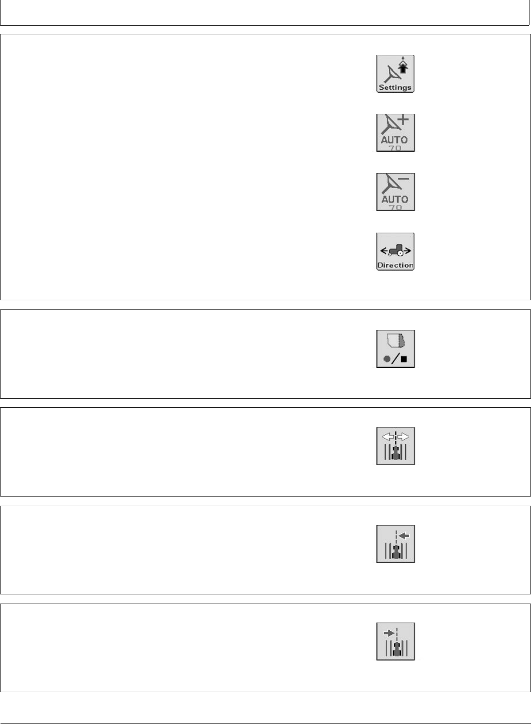
ShiftTrack – Go to the following Shift Track Controls.
Shift Track is used to adjust position of machine left,
center, or right of the set track. Shift track can be used to
compensate for GPS drift. Drift is inherent to any satellite
based, differentially corrected GPS system.
PC10857NC —UN—24SEP09
ShiftTrack
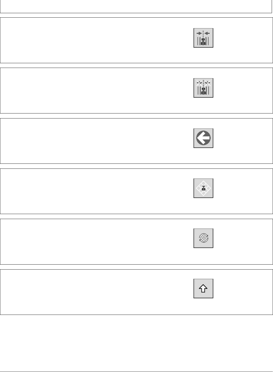
Shift Track Left PC10857LE —UN—14APR09
Shift Track Left
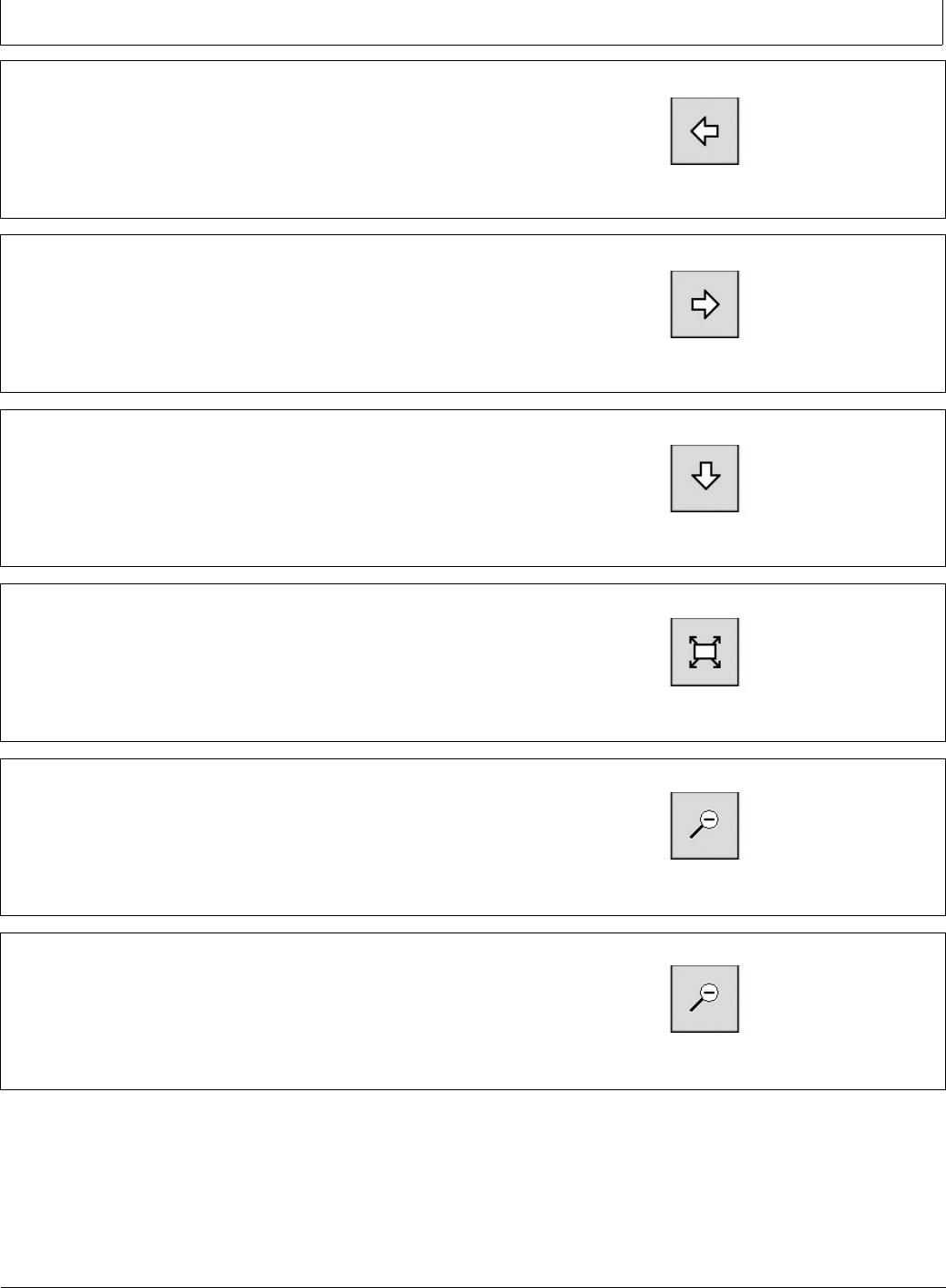
Shift Track Right PC10857LF —UN—14APR09
Shift Track Right
30-3 090811
PN=29
GS2 Display 1800
BA31779,000024B -19-01AUG11-8/23
BA31779,000024B -19-01AUG11-9/23
BA31779,000024B -19-01AUG11-10/23
BA31779,000024B -19-01AUG11-11/23
BA31779,000024B -19-01AUG11-12/23
Continued on next page BA31779,000024B -19-01AUG11-13/23
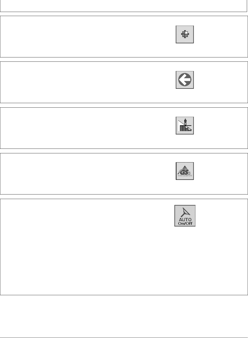
Shift Track Center PC10857LG —UN—14APR09
Shift Track Center
Clear Shifts PC10857LH —UN—14APR09
Clear Shifts
Back to Run Page Softkeys PC10857LI —UN—14APR09
Back button
Map Controls – Go to the following Map Controls PC10857LJ —UN—14APR09
Map Controls
Toggle Mapping Mode PC10857LK —UN—14APR09
Toggle Mapping Mode
Pan Map Up PC10857LM —UN—14APR09
Pan Map Up
30-4 090811
PN=30
GS2 Display 1800
BA31779,000024B -19-01AUG11-14/23
BA31779,000024B -19-01AUG11-15/23
BA31779,000024B -19-01AUG11-16/23
BA31779,000024B -19-01AUG11-17/23
BA31779,000024B -19-01AUG11-18/23
Continued on next page BA31779,000024B -19-01AUG11-19/23
Pan Map Left PC10857LN —UN—14APR09
Pan Map Left
Pan Map Right PC10857LO —UN—14APR09
Pan Map Right
Pan Map Down PC10857LP —UN—14APR09
Pan Map Down
Toggle Map Size – Selecting this button increases the
map to full screen, hiding the softkeys. Select the button
again to decrease the maps size and show the softkeys.
PC10857LQ —UN—14APR09
Toggle Map Size
Zoom Out PC10857LR —UN—14APR09
Zoom Out
Zoom In PC10857LR —UN—14APR09
Zoom In
30-5 090811
PN=31
GS2 Display 1800
BA31779,000024B -19-01AUG11-20/23
BA31779,000024B -19-01AUG11-21/23
BA31779,000024B -19-01AUG11-22/23
BA31779,000024B -19-01AUG11-23/23
CF86321,0000391 -19-01JUN11-1/1
Center Map – Centers the map on the vehicle. PC10857LT —UN—14APR09
Center Map
Back to Run Page Softkeys PC10857LI —UN—14APR09
Back Button
Swath Control ON/OFF Toggle PC10857LU —UN—14APR09
Swath Control ON/OFF Toggle
GreenStar – Go to GreenStar Main Page PC10857JN —UN—13APR09
GreenStar Main Page
Enabling AutoTrac
The following criteria must be met for AutoTrac to be
enabled:
•Vehicle has an AutoTrac capable steering controller
(ACI)
•Valid AutoTrac Activation (26 digit Activation Code)
•Setup Wizard is complete and a guidance track has
been created. See the GETTING STARTED section
earlier in this manual for Setup Wizard information
and see the sections on each Guidance Mode for
information on creating guidance tracks.
•Correct StarFire signal level for AutoTrac Activation is
selected (SF1, SF2, or RTK) and a valid GPS signal
is acquired.
•TCM turned on and TCM message is valid
PC13711 —UN—16MAY11
AutoTrac On/Off
•ACI has no active faults pertaining to the steering
function.
•Hydraulic oil warmer than minimum temperature
•Tractors - above 20°C (68°F)
•Forward vehicle speed is less than 30 km/h (18.6 mph)
•Reverse speed is less than 10 km/h (6 mph)
To Enable AutoTrac, select the Steer On/Off softkey
located on the Run Page. This softkey will disable
AutoTrac if selected again.
30-6 090811
PN=32
GS2 Display 1800
CF86321,0000392 -19-01JUN11-1/4
CF86321,0000392 -19-01JUN11-2/4
CF86321,0000392 -19-01JUN11-3/4
CF86321,0000392 -19-01JUN11-4/4
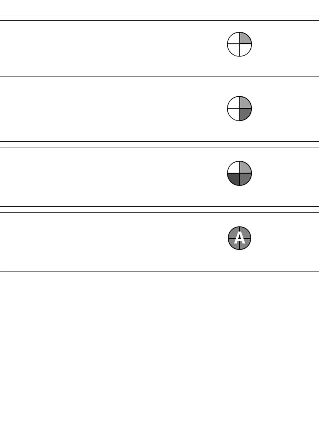
AutoTrac Status Pie
The AutoTrac Status Pie is shown at the bottom of the
Run Page as a quick diagnostic indicator.
INSTALLED (1/4 of pie)—AutoTrac Steering Controller
and all other necessary hardware are installed.
PC8832 —UN—25OCT05
Installed
CONFIGURED (2/4 of pie)—Valid AutoTrac Activation,
Tracking Mode has been determined and a valid Track
0 has been established. Correct StarFire signal level
for AutoTrac Activation is selected (SF1, SF2, or RTK).
Vehicle conditions met.
PC8833 —UN—25OCT05
Congured
ENABLED (3/4 of pie)—Steer On/Off softkey has been
selected.
PC8834 —UN—25OCT05
Enabled
ACTIVATED (4/4 of pie with “A”)—Resume switch is
pressed and AutoTrac is steering the vehicle.
PC8835 —UN—25OCT05
Activated
30-7 090811
PN=33
GS2 Display 1800
CF86321,0000393 -19-01JUN11-1/1
BA31779,0000240 -19-26JUL11-1/1
Reactivating AutoTrac on Next Pass
PC8866 —UN—02NOV05
Tracking
A—Track 0
B—Track 1 South
C—Track Spacing
D—Off-Track Lateral Error
E—Track Heading Error
Once the end of the row is reached, the operator must
turn system to next pass. By turning steering wheel,
AutoTrac is deactivated.
AutoTrac can be activated again by pressing Resume
Switch only after following conditions are met:
•Forward vehicle speed is less than 30 km/h (18.6 mph)
•Reverse speed is less than 10 km/h (6 mph).
•In reverse AutoTrac will remain activated for 45
seconds. After 45 seconds the machine must be put in
a forward gear before reverse will activate again.
•Vehicle heading is within 80° of desired track.
•The machine is within 40% of track spacing
•Operator is seated.
•TCM is on.
NOTE: The Track Number that is displayed at the top
of the RUN PAGE changes at half the distance
between two guidance tracks.
Deactivating AutoTrac
CAUTION: Always turn off (Deactivate and Disable)
AutoTrac system before entering a roadway.
To turn off AutoTrac, turn the Master Switch
to the OFF position.
AutoTrac system can be made DEACTIVE by the
following methods:
•Turning Master Switch to the OFF position.
•Turning steering wheel.
•Exceeding speed of 30 km/h (18.6 mph).
•Degradation of differential correction signal from SF2 or
RTK to WAAS/ EGNOS for longer than 3 minutes.
•Selecting the STEER ON/OFF button.
PC10857LA —UN—14APR09
Steer On/Off Softkey
•Operator out of seat for more than 7 seconds.
•Machine traveling less than 0.5 kph (0.3 mph) for 30
seconds.
•In reverse for longer than 45 seconds.
•Reverse speed exceeds 9.6 km/h (6 mph).
The master switch removes power from the EH Valve to
prevent AutoTrac from being unintentionally activated. The
master switch is intended for use on roadways or when
the operator does not want AutoTrac able to be activated.
30-8 090811
PN=34
GS2 Display 1800
CF86321,0000395 -19-01JUN11-1/2
CF86321,0000395 -19-01JUN11-2/2
Guidance Settings
Optimal performance of the GreenStar system usually
requires adjustment of settings. Access Guidance settings
to customize your user experience and optimize the
system performance.
General Settings
Turning View - assists the operator view the next track
when turning around. To turn ON/OFF, select / unselect
check box.
Turn Predictor - alerts operator by predicting the end of
pass. To turn ON/ OFF, select / unselect check box.
Tracking Tones – provide an audible indication off-track
error. To turn ON/ OFF, select / unselect check box. To
change distance at which tracking tones make a sound,
select input eld, scroll the thumb wheel to the desired
value, and press Enter. Values between 10—60 cm
(4—24 in.) may be entered.
Lead Compensation – shows how far down current track
guidance looks to for such things as turns. It is used with
PC10857JN —UN—13APR09
GreenStar Main Page
PC10857JF —UN—13APR09
Settings
PC10857NG —UN—27APR09
Guidance Settings
Parallel Tracking only. To turn ON/OFF, select / unselect
check box.
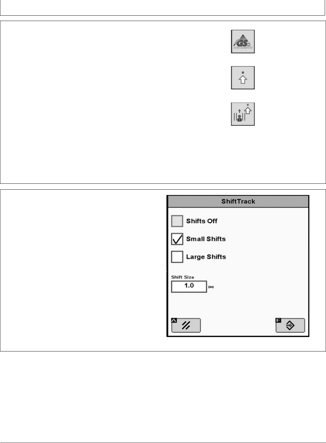
Shift Track – is used to adjust the position of guidance
tracks left or right to compensate for GPS drift. This
setting will turn shifts ON/OFF, select small shifts or large
shifts, and change the distance of each shift.
Shifts Off – Check the box to turn shifts OFF.
Small Shifts – Select Small Shifts to use a Shift Size of
1—30 cm (0.4—12 in.).
Large Shifts – Select Large Shifts to use a Shift Size of
1— 410cm (12-161.5 in.). Large Shifts are disabled when
AutoTrac is active or when operating in Adaptive Curve
Track mode.
Shift Size – Distance that tracks shift when SHIFT LEFT
or SHIFT RIGHT buttons are selected.
PC10857NH —UN—27APR09
30-9 090811
PN=35
GS2 Display 1800
BA31779,000024C -19-01AUG11-1/5
Continued on next page BA31779,000024C -19-01AUG11-2/5
AutoTrac Settings
NOTE: AutoTrac Settings only appear on the display
in machines that are AutoTrac capable.
Steering Sensitivity—Allows AutoTrac users to adjust
the vehicle’s steering sensitivity. To adjust steering
sensitivity select the input box and enter the desired
steering sensitivity value via numeric keypad and select
the enter button. The sensitivity can also be adjusted up
or down by selecting the Increase Steering Sensitivity and
Decrease Steering Sensitivity softkeys on the Run Page.
NOTE: Valid range for steer sensitivity is 50 - 200 with
200 being the most aggressive setting.
PC10857LB —UN—14APR09
Increase Steering Sensitivity
PC10857LC —UN—14APR09
Decrease Steering Sensitivity
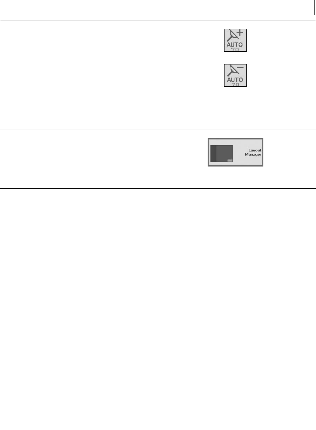
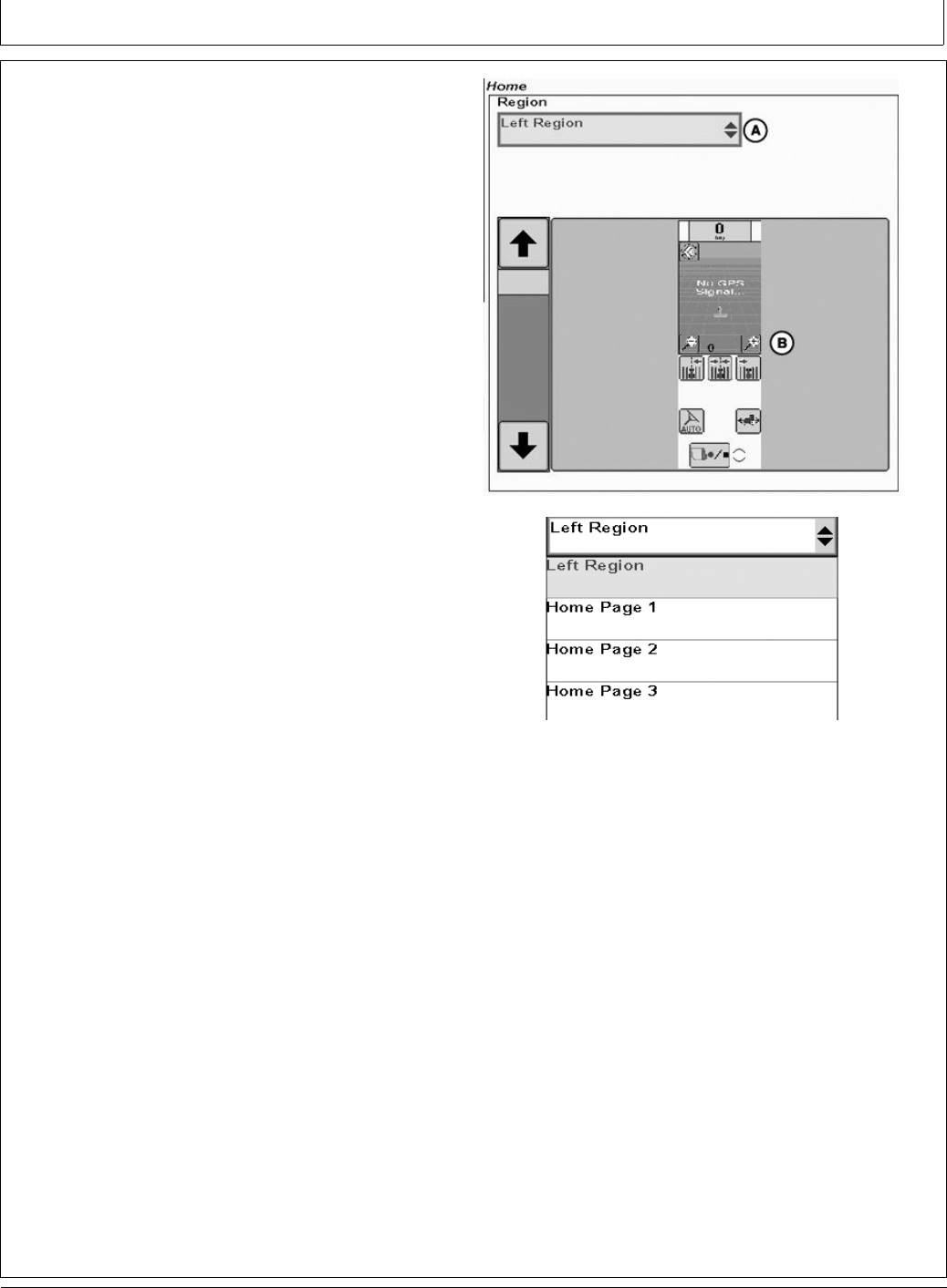
Direction Toggle
To be able to select the Direction Toggle Button the left
region of the home page must be setup correctly. Setting
up the left hand region will also allow the user to perform
other operations.
1. Select the Layout Manager Button from the main menu
PC13727 —UN—16MAY11
Layout Manager Button
30-10 090811
PN=36
GS2 Display 1800
BA31779,000024C -19-01AUG11-4/5
BA31779,000024C -19-01AUG11-5/5
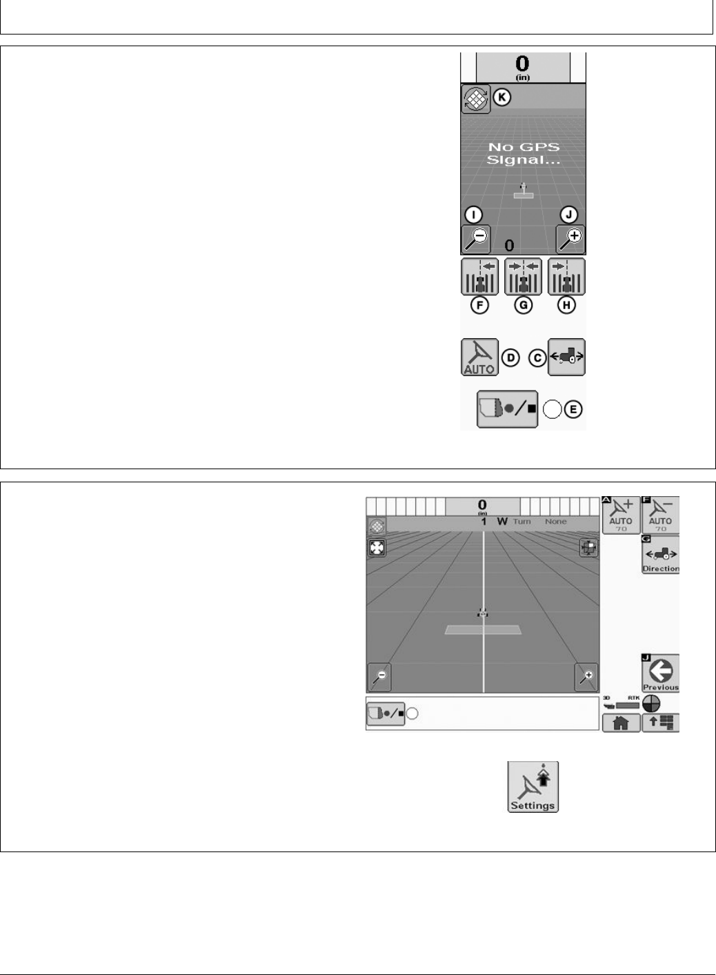
3. In the setup selection (B) of the layout manager home
screen select the left region that displays the Direction
Toggle button (C).
A—Drop Down Menu
B—Setup Selection
C—Direction Toggle
D—AutoTrac On/Off
E—Recording
F— Shift Track Left
G—Center Track
H—Shift Track Right
I— Zoom Page Out
J— Zoom Page IN
K—Toggle Mapping Mode
PC13736 —UN—16MAY11
Left Region
The Direction toggle button can also be displayed on the
right hand side of the Run Page by selecting the Settings
Button on the run page.
PC13963 —UN—01AUG11
Run Page
PC13959 —UN—01AUG11
Settings
30-12 090811
PN=38

GS2 Display 1800
Continued on next page CF86321,0000397 -19-01JUN11-1/4
Advanced AutoTrac Settings
To access the Advanced AutoTrac settings select the
GreenStar button, select Settings Button, then select
AutoTrac Settings from the Settings home page.
PC10857JN —UN—13APR09
GreenStar
PC10857JF —UN—13APR09
Settings
PC13713 —UN—16MAY11
AutoTrac Settings
30-13 090811
PN=39
GS2 Display 1800
Continued on next page CF86321,0000397 -19-01JUN11-2/4
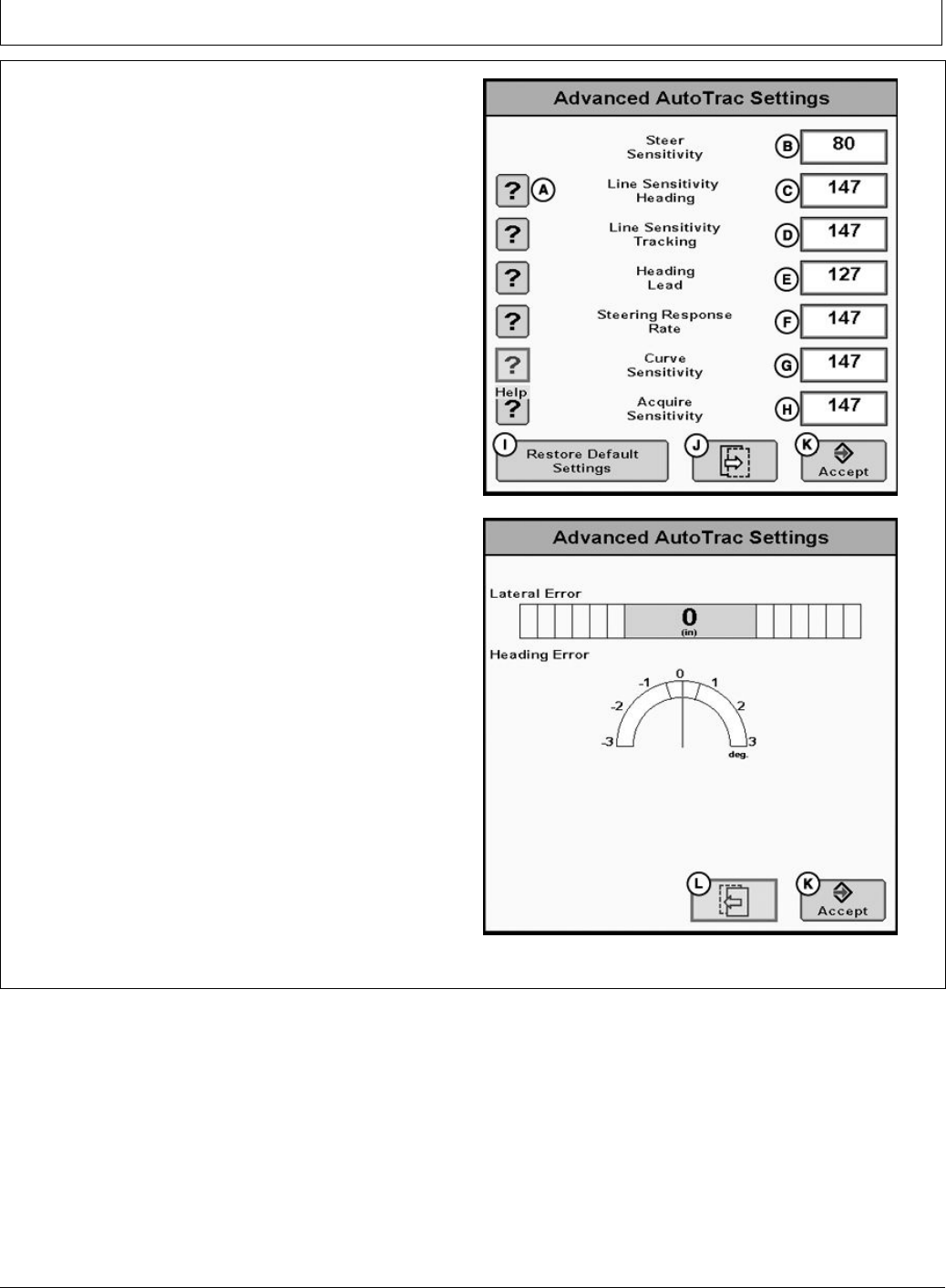
The AutoTrac Settings button will only be visible under
Guidance Settings when an Steering Controller that
supports advanced AutoTrac Integrated settings is
detected.
The Accept button (K) saves and applies the current
settings and returns the user to the previous page. The
Restore Default Settings button (I) will set all settings to
the factory default value. See each setting for its default
value. Next page (J ) will take the user to page 2 of the
Advanced AutoTrac Settings. Selecting Previous page (L)
will take the user to page 1 of the Advanced AutoTrac
Settings The ‘?’ button (A) will display a popup with help
text for the specic setting.
A—Help
B—Steer Sensitivity
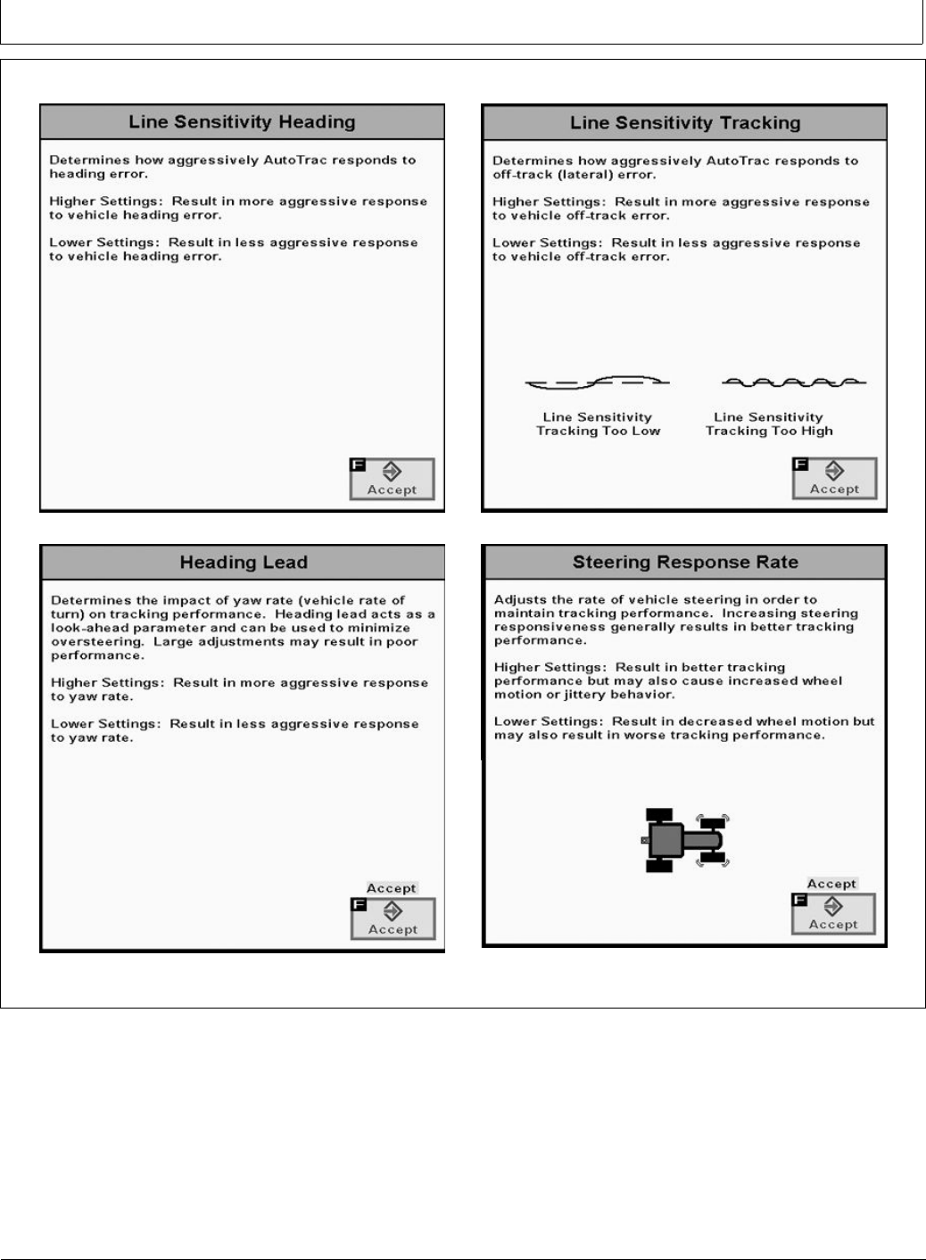
C—Line Sensitivity Heading
D—Line Sensitivity Tracking
E—Heading Lead
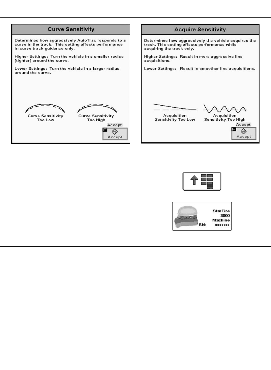
F— Steering Response Rate
G—Curve Sensitivity
H—Acquire Sensitivity
I— Restore Default Settings
J— Next Page
K—Accept
L— Previous Page
PC13714 —UN—16MAY11
Advanced Settings
PC13715 —UN—16MAY11
Advanced Settings
30-14 090811
PN=40
GS2 Display 1800
CF86321,0000397 -19-01JUN11-4/4
Continued on next page BA31779,0000225 -19-08JUL11-1/2
PC13724 —UN—16MAY11
Curve Sensitivity
PC13725 —UN—16MAY11
Acquire Sensitivity
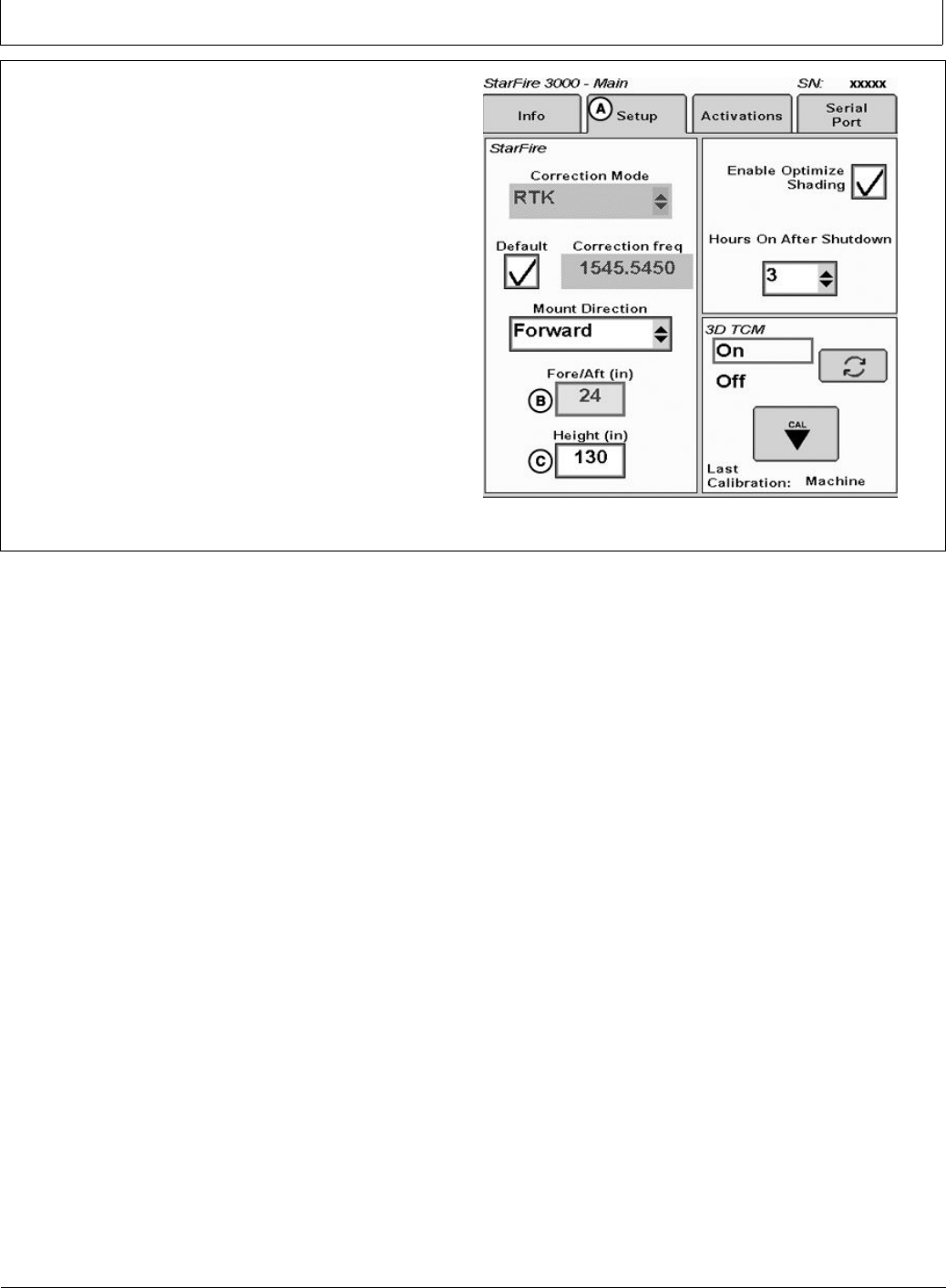
StarFire
AutroTrac controller takes its StarFire Height and Fore-Aft
measurements from the StarFire setup. To change
this information select the menu button then select the
StarFire button. The StarFire main page will appear.
Select the Setup tab (A) at the top of the screen.
PC8663 —UN—05AUG05
Menu Button
PC13738 —UN—17MAY11
SF3000 Button
30-16 090811
PN=42
GS2 Display 1800
BA31779,0000225 -19-08JUL11-2/2
StarFire Height (in.) Enter the height of the StarFire
receiver into the Height box (C) of the StarFire Setup
screen. Height is measured from the ground to the center
(where the green and yellow meet) of the dome.
StarFire Fore-Aft (in.) Enter the Fore-Aft measurement
into the Fore/Aft box (B) of the StarFire Setup screen.
This is the distance from the xed axle of the machine to
the receiver. The xed axle is the rear axle on a row crop
tractor. The xed axle is the front axle on an articulated
tractor
NOTE: For more information on StarFire setup
see the StarFire operators manual that
matches your equipment.
PC13726 —UN—19MAY11
StarFire Setup Screen
30-17 090811
PN=43
Troubleshooting—GS2 Display 1800
CF86321,0000331 -19-23MAY11-1/1
Continued on next page CF86321,0000332 -19-23MAY11-1/2
Trouble Codes
Select TROUBLE CODES button, a list of controllers will
appear and controllers with diagnostic codes are indicated.
Individual controllers can be accessed by navigating with
rotary thumb wheel and selected by pressing ENTER
button, to view codes for that controller.
Codes can also be displayed for all controllers by selecting
SHOW ALL button with rotary thumb wheel and pressing
ENTER button. Codes can be relayed to a John Deere
dealer to assist in diagnosing machine problems.
PC8663 —UN—05AUG05
MENU button
PC8655 —UN—05AUG05
MESSAGE CENTER button (With Info Icon)
PC8669 —UN—05AUG05
TROUBLE CODES softkey
Diagnostic Addresses
MESSAGE CENTER button >> DIAGNOSTIC
ADDRESSES softkey >> DEVICE drop down box >>
“VT;.001 Implement”
PC8655 —UN—05AUG05
MESSAGE CENTER button
PC8668 —UN—05AUG05
DIAGNOSTIC ADDRESSES softkey
35-1 090811
PN=44
Troubleshooting—GS2 Display 1800
CF86321,0000332 -19-23MAY11-2/2
PC8665 —UN—05AUG05
COMPONENTS AND SOFTWARE VERSIONS softkey
PC8666 —UN—05AUG05
SOFTWARE INFORMATION softkey
PC8667 —UN—05AUG05
MESSAGES softkey
PC8668 —UN—05AUG05
DIAGNOSTIC ADDRESSES softkey
PC8669 —UN—05AUG05
TROUBLE CODES softkey
PC8670 —UN—05AUG05
Electronic CONTROL UNIT INFORMATION softkey
PC8671 —UN—05AUG05
BUS INFORMATION softkey
Message center will display all active alarm messages.
35-2 090811
PN=45

Troubleshooting—GS2 Display 1800
Continued on next page CF86321,0000333 -19-23MAY11-1/2
Guidance Alarms
ACI Communication Error No communication with vehicle steering controller (Steering Controller). Check vehicle for diagnostic codes
and contact your John Deere Dealer.
Turn Predictor Turned On Turn predictor is turned ON. Use the check box to turn it OFF
AutoTrac Deactivated AutoTrac system deactivates when operator is out of seat for more than 5 seconds
AutoTrac The operator is responsible for collision avoidance. Turn AutoTrac OFF before entering roadways.
Data Card Problem! A data card must be inserted in the compact ash drive with the door closed to use the GreenStar2 Pro
application.
No Setup Data! Setup data for the GreenStar2 Pro application could not be found on the data card. The GreenStar2 Pro
application will not be available until a data card with setup data is inserted
AutoTrac Steering Controller
Software Incompatible
See your John Deere Dealer for Steering Controller update.
Communication Error Communication problem with controller. Check connections to controller.
Mobile Processor Detected Mobile Processor Detected on CAN Bus. GreenStar Application is disabled. Remove mobile processor
and cycle power to enable GreenStar application.
GPS Communication Problem No communication with GPS receiver. Check connections at GPS receiver.
Tracking Inaccurate The GPS receiver must be set to report at the 5Hz message output rate. Conrm settings on GPS receiver
and change output to 5Hz,
Invalid Boundary An invalid boundary has been recorded. You may continue recording or clear the current boundary and start
recording again.
Activation Error Invalid activation code. Please reenter activation code.
Invalid Filter All the elds that are required to be lled out based on the Totals Type Selected have not been lled out.
Flags of Same Selection Selected the Flags of same name and mode.
Name Already Exists The name you have entered already exists in this list. Please enter a new name.
Alarms
GPS Communication Problem No communication with GPS receiver. Check connection at GPS receiver and perform operation again.
Curve Track Memory Full Internal memory available for Curve Track is full. Data must be cleared to continue Curve Track Operation.
Clear curved track data from system
AutoTrac Disabled AutoTrac SF1 license cannot operate with current StarFire software. Update StarFire software to operate
AutoTrac.
AutoTrac Disabled AutoTrac SF1 license cannot operate while SF2 corrections are turned on. Turn SF2 corrections off to
operate AutoTrac.
License Problem No license available for the selected tracking mode. Previous tracking mode will be selected.
Duplicate Name Name already exists. Select another name.
Curve Track Recording Curve Track recording in progress. Cannot perform operation until recording is turned off.
Circle Denition Problem There was an internal error during Circle denition. Redene the circle.
Circle Denition Problem Communication with GPS receiver was lost during circle denition. Redene the circle once communication
has been re-established.
Circle Denition Problem Center point is too far. Select another center point.
A-B Line Denition Problem There was an internal error during A-B line denition. Redene the A-B line.
A-B Line Denition Problem A timeout occurred during A-B line denition. Redene the A-B line.
A-B Line Denition Problem A and B points of the A-B line are too close. Perform operation again.
Loss of GPS While Recording
Boundary
GPS has been lost while recording the boundary. Point logging will resume when the GPS signal returns. This
may result in an inaccurate boundary.
Data Card Full Unload and cleanup data card or insert new data card.
Data Card 90% Full Unload and cleanup data card or insert new data card.
No Memory No Memory available for Curve Track. Unload and cleanup data card or insert new data card.
Low Memory Low Memory available for Curve Track. Unload and cleanup data card or insert new data card.
No Memory No Memory available for Straight Track. Unload and cleanup data card or insert new data card.
No Memory No Memory available for Circle Track. Unload and cleanup data card or insert new data card.
Circle Denition Problem The distance from the vehicle to the center point is greater than 1 mile. Select another center point or drive
another circle.
Zero All Totals You have decided to zero all totals for the selected lter.
Incorrect RS232 Controller Model
Selected
The RS232 controller model selected is incorrect. Please verify and reenter manufacturer and model number.
Prescription Error Controller is not setup to accept prescriptions.
35-3 090811
PN=46

Troubleshooting—GS2 Display 1800
CF86321,0000333 -19-23MAY11-2/2
CF86321,0000334 -19-23MAY11-1/1
Prescription Error Controller is setup to accept prescriptions. No controller prescription has been selected.
Prescription Error Prescription rate is out of controller range.
Controller Unit of Measure Error Controller will only operate when using metric units.
Controller Unit of Measure Error Controller will only operate when using English (US) units.
Controller Unit of Measure Error Controller will only operate when using metric or English (US) units.
Controller Operation Error Invalid operation selected for controller.
Prescription Warning Out of eld prescription rate is now being applied.
Prescription Warning Loss of GPS signal has occurred. Loss of GPS prescription rate is now being applied.
Prescription Warning Controller does not support selected prescription.
INFO
AutoTrac Deactivation Message
AutoTrac deactivation message–Each time AutoTrac
is deactivated text is displayed indicating the reason
why AutoTrac deactivated. Messages are also displayed
as to why AutoTrac did not activate. The deactivation
messages display for 3 seconds and then disappear.
AutoTrac Deactivation Message
Deactivation Message Description
Steering wheel moved Operator turned steering wheel
Speed too slow Vehicle speed is below minimum required speed
Speed too fast Vehicle speed is above maximum allowed speed
Invalid gear Vehicle operating in an invalid gear
Track number changed Track number changed
Invalid GPS signal SF1, SF2, or RTK signal was lost
Steering Controller fault See John Deere dealer
Invalid display messages Check display settings
Invalid display settings Check guidance settings and Track 0 setup
No AutoTrac Activation No AutoTrac Activation on GS2
Heading error too large Vehicle is at an angle greater than 45 degrees from track
Offtrack error too large Vehicle not within 40% of track spacing
Out of seat Out of seat too long
Oil temp too cold Hydraulic oil not above minimum required temperature
No TCM corrections Make sure TCM is turned on
Invalid Steering Controller activation Need Steering Controller activation code.
See John Deere dealer.
FICA in diagnostic mode Fuse is in diagnostic slot in vehicle fuse box. remove fuse.
Header off Header was turned off
Road mode In transport gear
Invalid Steering Controller voltage See John Deere dealer
Reverse timeout In reverse gear for more than 45 seconds
Vehicle too slow AutoTrac below minimum speed
Curve too sharp Maximum curvature has been exceeded
Vehicle not moving in a forward direction Vehicle must be in forward gear to activate
Vehicle shutting down Vehicle is shutting down
Gear data error See John Deere dealer
Resume switch error See John Deere dealer
Keyswitch error See John Deere dealer
SPFH AutoTrac switch is not on Make sure SPFH AutoTrac switch is turned on
SPFH Quick Stop switch is on Make sure SPFH Quick Stop switch is turned off
35-4 090811
PN=47
Troubleshooting—GS2 Display 1800
Continued on next page CF86321,0000335 -19-23MAY11-1/2
Diagnostic Addresses
Diagnostic Addresses
NOTE: Diagnostic addresses are available to access
specic diagnostic information. This information
can assist the John Deere Dealer in diagnosing
problems. Different device controllers can be
selected from drop-down box, as shown.
Select DIAGNOSTIC ADDRESSES button. The
number of devices available will depend upon machine
conguration. The list of addresses can be scrolled up or
down with rotary thumb wheel. Selecting an address will
show data for that address.
PC8663 —UN—05AUG05
MENU button
PC8655 —UN—05AUG05
MESSAGE CENTER button (With Info Icon)
PC8668 —UN—05AUG05
DIAGNOSTIC ADDRESSES softkey
Address Number Address Name
008 Unswitched Power Supply Voltage
009 Switched Power Supply Voltage
010 Unit Internal Temperature
011 Vehicle CAN - Bus Status
012 Vehicle CAN - CAN HIGH Voltage
013 Vehicle CAN - CAN LOW Voltage
015 Implement CAN - Bus Status
016 Implement CAN - CAN HIGH Voltage
017 Implement CAN - CAN LOW Voltage
018 Flash Wear Count
019 Hours of Operation
020 1.5 v Regulated Power Supply Voltage
021 3.3 v Regulated Power Supply Voltage
022 5.0 v Regulated Power Supply Voltage
023 Radar Input Status
024 Implement Switch Status
025 External Analog Input Voltage
026 Compact Flash Drive Status
028 CCD Bus - Bus Status
029 CCD Bus - Positive Voltage
030 CCD Bus - Negative Voltage
031 Bezel Key Status
032 Real Time Clock (RTC)
033 Maximum Sleep Time
038 Synchronize Brightness
039 Daytime Luminance
040 Daytime Luminance Balance Ratio
041 Nighttime Luminance
042 Nighttime Luminance Balance Ratio
35-5 090811
PN=48

Troubleshooting—GS2 Display 1800
CF86321,0000335 -19-23MAY11-2/2
Address Number Address Name
043 Internal Speaker Volume
044 Display ISO Function Instance
045 Settings - Country Code
046 Settings - Language Code
047 Settings - Numeric Format
048 Settings - Date Format
049 Settings - Time Format
050 Settings - Units of Distance
051 Settings - Units of Area
052 Settings - Units of Volume
053 Settings - Units of Mass
054 Settings - Units of Temperature
055 Settings - Units of Pressure
056 Settings - Units of Force
057 Settings - GPS Time Sync
058 Settings - Current Date
059 Settings - Current Time
060 Radar Calibration Constant
227 Boot Block Program Part Number (Software)
228 Boot Block Program Version Number (Software)
231 Board Service Package Part Number (Software)
232 Board Service Package Version Number (Software)
233 Virtual Terminal Part Number (Software)
234 Virtual Terminal Version Number (Software)
235 Device Part Number (Hardware)
236 Device Serial Number (Hardware)
247 Current Vehicle Model Number
248 Current Vehicle Serial Number
249 Original Vehicle Model Number
250 Original Vehicle Serial Number
35-6 090811
PN=49
GS3 2630 Display
CF86321,000039A -19-28JUN11-1/1
Enabling System
PC13825 —UN—28JUN11
GreenStar Pro
A—View Tab
B—Guidance Settings Tab
C—ShiftTrac Settings
D—AutoTrac Status Pie
E—Change Direction Toggle
Button
Press STEER ON/OFF button to toggle between
enable/disable AutoTrac.
To enable system, all of the following criteria must be met:
•AutoTrac activation is detected.
•Track 0 has been setup.
•Tracking mode selected.
•Proper operator presence mode selected.
•TCM must be installed and turned on.
•AutoTrac Controller Steering Kit is plugged in.
40-2 090811
PN=51
GS3 2630 Display
CF86321,000039B -19-01JUN11-1/1
BA31779,0000244 -19-26JUL11-1/1
Activating System
CAUTION: While AutoTrac is activated, operator
is responsible for steering at end of path
and collision avoidance.
Do not attempt to turn on (Activate) AutoTrac
system while transporting on a roadway.
After system has been ENABLED, operator must manually
change system to ACTIVATED status when steering
assistance is desired.
Press resume switch. This will initiate assisted steering.
In order to activate system following criteria must be met:
•Vehicle speed is greater than 0.5 km/h (0.3 mph).
•Forward vehicle speed is less than 30 km/h (18.6 mph)
•Reverse vehicle speed is less than 10 km/h (6.0 mph).
•Vehicle within 45 degrees of desired track.
•Operator is seated.
•TCM is on.
•In reverse AutoTrac will remain activated for 45
seconds. After 45 seconds the machine must be put in
a forward gear before reverse will activate again.
Deactivating System
CAUTION: Always turn off (Deactivate and Disable)
AutoTrac system before entering a roadway.
To turn off AutoTrac, turn the Master Switch
to the OFF position.
AutoTrac system can be made DEACTIVE by following
methods:
•Turning Master Switch to the OFF position.
•Turning steering wheel.
•Slowing to speeds less than 0.5 km/h (0.3 mph).
•Exceeding forward speed of 30 km/h (18.6 mph)
•Exceeding reverse speed of 10 km/h (6.0 mph).
•Toggle STEER ON/OFF button until STEER OFF is
displayed in GUIDANCE VIEW tab.
•Operator out of seat for more than 5 seconds if using
seat switch or no activity detected by operator presence
monitor for 7 minutes.
The master switch removes power from the EH Valve to
prevent AutoTrac from being unintentionally activated. The
master switch is intended for use on roadways or when
the operator does not want AutoTrac able to be activated.
40-3 090811
PN=52
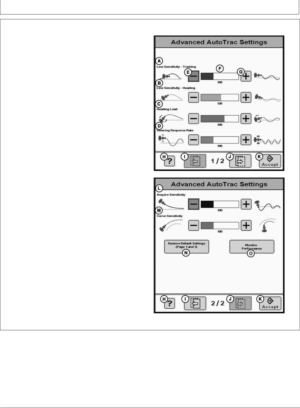
GS3 2630 Display
CF86321,000039D -19-01JUN11-1/1
Setup
Advanced AutoTrac Settings
The accept button (K) shall save and apply the current
settings and return the user to the previous page. The
Restore Default Settings button (K) will set all settings
to the factory default value. See each setting for its
default value. The ‘?’ button (H) will display a pop-up
with help information. Refer to Advanced settings —
Optimizing AutoTrac Controller Performance section
of this operator manual for more information.
NOTE: When using the number pad, increase, and
decrease buttons, the change occurs immediately
without pressing the enter button.
When no seat switch is present, the AutoTrac
Controller will look for operator activity every seven
minutes. Operator will get a time out alarm 15
seconds before AutoTrac will deactivate. Pressing
resume will reset activity monitor timer
IMPORTANT: Use AutoTrac Controller only on Ap-
proved Vehicles – see www.StellarSupport.com
for list of approved vehicles
It is important that the operator stay seated
while vehicle is moving.
A—Line Sensitivity-Tracking
B—Line Sensitivity-Heading
C—Heading Lead
D—Steering Response Rate
E—Decrease Button
F— Value
G—Increase Button
H—Help Button
I— Page Back Button
J— Page Forward Button
K—Accept Button
L— Aquire Sensitivity
M—Curve Sensitivity
N—Restore Defaults
O—Monitor Performance
PC13568 —UN—04MAY11
Advanced Settings Page 1
PC13569 —UN—04MAY11
Advanced Settings Page 2
40-4 090811
PN=53
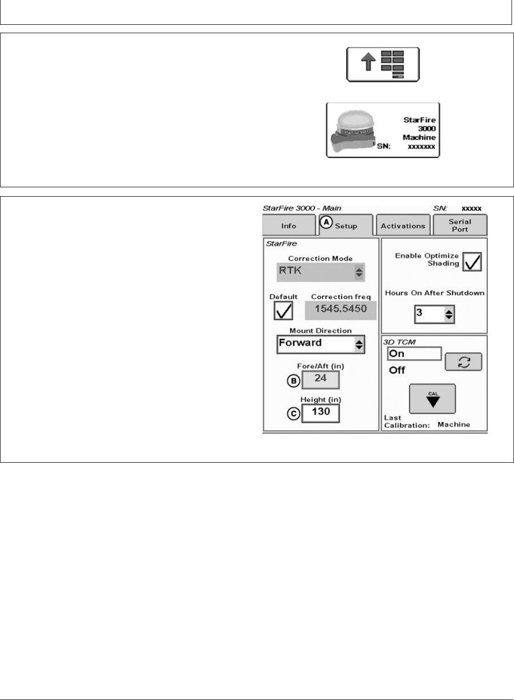
GS3 2630 Display
BA31779,0000226 -19-08JUL11-1/2
BA31779,0000226 -19-08JUL11-2/2
StarFire
AutroTrac controller takes its StarFire Height and Fore-Aft
measurements from the StarFire setup. To change
this information select the menu button then select the
StarFire button. The StarFire main page will appear.
Select the Setup tab (A) at the top of the screen.
PC8663 —UN—05AUG05
Menu Button
PC13738 —UN—17MAY11
SF3000 Button
StarFire Height (in.) Enter the height of the StarFire
receiver into the Height box (C) of the StarFire Setup
screen. Height is measured from the ground to the center
(where the green and yellow meet) of the dome.
StarFire Fore-Aft (in.) Enter the Fore-Aft measurement
into the Fore/Aft box (B) of the StarFire Setup screen.
This is the distance from the xed axle of the machine to
the receiver. The xed axle is the rear axle on a row crop
tractor. The xed axle is the front axle on an articulated
tractor
NOTE: For more information on StarFire setup
see the StarFire operators manual that
matches your equipment.
PC13726 —UN—19MAY11
StarFire Setup Screen
40-5 090811
PN=54

GS3 2630 Advanced Settings
Continued on next page CF86321,000027B -19-16MAY11-1/2
Tuning Recommendations
NOTE: AutoTrac Controller has been tuned to perform
very well in most eld conditions using the
variety of implements encountered by AutoTrac.
However, for those conditions outside of normal,
we have provided Advanced Settings to allow
the operator ne tune their systems for specic
eld conditions and implements.
Problem or Situation:
AutoTrac performance during line acquisitions, Curve Trac
or in-row S-ing that can’t be tuned out using the Steering
Sensitivity adjustment.
Difcult ground conditions (extremely soft or extremely
rough) require additional tuning beyond the capabilities of
the standard Steering Sensitivity value.
Read this information in it’s entirety BEFORE tuning
AutoTrac Advanced Settings.
This software version includes 6 different tunable
sensitivities that allow ner adjustment of the AutoTrac
system. The following are details for tuning this
software:
1. Check & x other problems before you
tune—Perform necessary mechanical checks and
calibrations through associated tractor. It is important
to do this step rst otherwise you run the risk of
masking actual machine faults and wasting your time
tuning a system that cannot be tuned.
2. Characterize the current AutoTrac problem—There
are various types of issues this software may be able
to resolve. First, the specic type of problem needs to
be identied from the possible items below:
a. Excessive Wheel Motion—Overall AutoTrac
performance is acceptable, but the operator is
concerned about how quickly the wheels are
twitching back and forth.
b. Aggressive S-ing Motion—Continual back and
forth motion as observed by the operator looking
out over the front nose of the tractor. Although a lot
of motion is observed, the off-track error shown on
the display (distance away from AB line) is often
relatively small.
c. Lazy S-ing Motion—Performance of AutoTrac
seems very sluggish when trying to stay on the line
and slowly wanders from side to side.
d. Lazy Line Acquisition—AutoTrac appears
sluggish during line acquisition and the tractor
remains off to one side of the line for a long time
before getting lined up.
e. Aggressive Line Acquisition—AutoTrac
overshoots the line, and continues to
overcompensate during acquisition. Results in high
frequency, tight S-ing pattern during acquisitions.
f. Lazy Curve Track Performance—AutoTrac is
sluggish in Curve Track mode resulting in slow,
wandering S-ing about the desired line and often
tracks to the outside of the desired path.
g. Aggressive Curve Track Performance—AutoTrac
exhibits rapid and high frequency corrections in
Curve Track mode, resulting in a tight S-ing pattern
or tracking to the inside of the desired path.
3. Access the Advanced Settings page on GS2.
4. ATI Advanced Settings Parameters.
a. Line Sensitivity Heading: Determines how
aggressively AutoTrac responds to heading error.
Higher Settings: Result in more aggressive
response to vehicle heading error.
Lower settings: Result in less aggressive response
to vehicle heading error.
Range: 50 to 200.
b. Line Sensitivity Tracking (Lateral Gain):
Determines how aggressively AutoTrac responds
to off-track (lateral) error.
Higher settings: Result in more aggressive
response to vehicle off-track error.
Lower settings: Result in less aggressive response
to vehicle off-track error.
Range: 50 to 200.
c. Heading Lead: Determines the impact of yaw
rate (vehicle rate of turn) on tracking performance.
Heading lead acts as a look-ahead parameter and
can be used to minimize over steering. Large
adjustments may result in poor performance.
Higher settings: Result in more aggressive
response to yaw rate.
Lower settings: Result in less aggressive response
to yaw rate.
Range: 50 to 130.
d. Steering Response Rate: Adjusts the rate of
vehicle steering in order to maintain tracking
performance. Increasing steering responsiveness
generally results in better tracking performance.
Higher settings: Result in better tracking
performance but may also cause increased wheel
motion or jittery behavior.
Lower settings: Results in decreased wheel motion
but may also result in worse tracking performance.
Range: 50 to 200.
e. Curve Sensitivity: Determines how aggressively
AutoTrac responds to a curve in the track. This
setting affects performance in curve track guidance
only.
45-1 090811
PN=55

GS3 2630 Advanced Settings
CF86321,000027B -19-16MAY11-2/2
Higher settings: Turn the vehicle in a smaller radius
(tighter) around the curve.
Lower settings: Turn the vehicle in a larger radius
around the curve.
Range: 50 to 200.
f. Acquire Sensitivity: Determines how aggressively
the vehicle acquires the track. This setting affects
performance while acquiring the track only.
High settings: Result in more aggressive line
acquisitions.
Lower settings: Result in smoother line acquisitions.
Range: 50 to 200.
5. Follow Tuning Instructions—First try to adjust the
settings based on how it was characterized in Step 2.
If familiar with how the settings affect performance,
proceed to the general tuning instructions if desired.
Although the customer’s comfort needs to be taken
into account, try to tune the tractor based on lateral
error on the GS2 and the tracks that tractor leaves
behind. After nding a reasonable set of parameters,
try running the tractor at different speeds to ensure the
settings are still acceptable. Sometimes the settings
that maximize AutoTrac performance are very close to
making the operator feel uncomfortable.
General Tuning Instructions
Adjustment Recommendations:
•Steering Sensitivity—Set at 100 before making
other adjustments – after that make adjustments in
increments of 10.
•Line Sensitivity Tracking—Adjust in increments of 20.
•Line Sensitivity Heading—Adjust in increments of 10.
•Heading Lead—Adjust in increments of 10.
•Steering Response Rate—Adjust in increments of 10.
•Acquire Sensitivity—Adjust in increments of 20.
•Curve Sensitivity—Adjust in increments of 20.
One Value at a Time—Attempt to adjust the settings in
the problem eld conditions while AutoTrac is active.
1. Start with the factory default settings. The Steering
Sensitivity value will correlate to the value on the
Guidance View Tap. Attempt to use a value for this
setting that is similar to the conditions in which you are
running (70 for concrete, 100 most conditions, 120
for soft ground). This number may still need to be
modied beyond the suggested settings.
2. While AutoTrac is active in the problem conditions
(speeds, ground, tire setup, etc), increase/reduce the
Line Sensitivity Heading by a factor of 10.
3. If the change in Line Sensitivity Heading is ineffective
at addressing the issue, reset the Line Sensitivity
Heading parameter and increase/reduce the Heading
Lead in the same manner as the previous step.
4. If none of the previous steps were effective reset
the Heading Lead and increase/reduce the Steering
Response Rate in a similar fashion to the previous
steps.
Combining Settings—If the above procedure does not
give satisfactory performance and once you have become
more comfortable with how the parameters change
AutoTrac performance (as detailed in the previous step),
try different combinations of parameters while AutoTrac is
active. The following chart should be used as a reference
and contains suggested values based on various types
of conditions, please note that values may need to be
adjusted beyond these recommendations to achieve
satisfactory performance.
To return all settings to their default values, use the
“Return To Defaults” button provided at the bottom of the
Advanced Settings screen.
45-2 090811
PN=56

GS3 2630 Advanced Settings
CF86321,000027C -19-16MAY11-1/1
Recommended Tuning Settings
Settings Factory Defaults Min Value Max Value Excessive Wheel
Motion
Aggressive S-ing
Motion
Lazy S-ing Motion
Overall Steering
Sensitivity
70 50 200 100 100 100
Line Sensitivity
Heading
100 50 200 100-Decrease as
necessary
80-Decrease as
necessary (start
here)
100-Increase as
necessary (start
here)
Line Sensitivity
Tracking
100 50 200 100 100 100-Increase as
necessary
Heading Lead 100 50 130 90 90-Decrease as
necessary
90
Steering
Response Rate
100 50 200 80-Decrease as
necessary (start
here)
100 100-Increase as
necessary
Curve Sensitivity 70 50 200 100 100 100
Acquire
Sensitivity
100 50 200 100 100 100
Settings Wandering S-ing
Motion
Lazy Line
Acquisitions
Aggressive Line
Acquisitions
Lazy Curve Track
Performance
Aggressive Curve
Track Performance
Overall Steering
Sensitivity
100 100 100 100 100
Line Sensitivity
Heading
100-Decrease as
necessary
100 100-Decrease as
necessary
100-Increase as
necessary
100-Decrease as
necessary
Line Sensitivity
Tracking
100-Increase as
necessary
150-Increase as
necessary
100-Decrease as
necessary
100 100
Heading Lead 100-Increase as
necessary (start here)
90 90 90-Increase as
necessary
90
Steering Response
Rate
100-Increase as
necessary
100 100 100-Increase as
necessary
100
Curve Sensitivity 70 100 100 110-Increase as
necessary (start here)
90-Decrease as
necessary (start here)
Acquire Sensitivity 100 120-Increase as
necessary (start here)
80-Decrease as
necessary (start here)
100 100
Most Common Conditions
1. Excessive Wheel Motion—Adjust Steering Response
Rate rst before making any other adjustments. Turn
down this parameter until an acceptable amount of
wheel motion exists. Although it may be possible for
this parameter to be changed independently, you may
need to increase Line Sensitivity Heading and/or Line
Sensitivity Tracking (lateral) gains to compensate for
the wheel motion decrease. Keep in mind that forcing
this value too low may compromise AutoTrac accuracy
because this responsiveness determines how quickly
the system can compensate for off-track error. The
recommended Steering Wheel Speed setting should
be adjusted until there is slightly less wheel motion
than what is considered excessive by the operator.
2. Aggressive S-ing Motion—The two main
adjustments to address aggressive s-ing motion are
Line Sensitivity Heading and Heading Lead. Start
by increasing Heading Lead to enable the system to
look further ahead when making corrections. If this
is unsuccessful, the likely cause is overaggressive
Line Sensitivity Heading and this gain should then
be reduced. Forcing this gain low may require an
increase in the Line Sensitivity Tracking (Lateral) gain
to maintain the overall system performance at an
acceptable level.
3. Lazy S-ing Motion—This may be the most difcult
situation to address because the sluggish behavior
can be caused by eld conditions or machine setup.
In some cases, tuning the gains may not achieve
the performance desired. Start by increasing Line
Sensitivity Tracking and check performance. If the
system remains sluggish, increase Line Sensitivity
Heading until the system begins to respond more
aggressively. If ne tuning is needed, the Steering
Response Rate can be adjusted accordingly,
increasing this value will make the system more
aggressive.
45-3 090811
PN=57
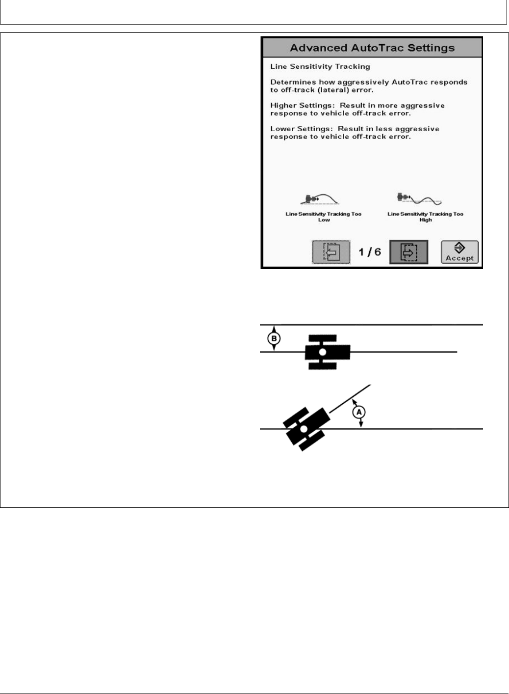
GS3 2630 Advanced Settings
Continued on next page CF86321,000027D -19-16MAY11-1/9
Optimizing AutoTrac Controller Performance
When operating in curves, start with the curve sensitivity
equal to the optimized acquire sensitivity.
These default settings are a good starting point for most
conditions. Each setting can be adjusted to try and
optimize performance. Operator may need to readjust
line sensitivity - heading and line sensitivity - tracking for
best results. Increase or decrease settings to change
aggressiveness as desired. If system is not responsive
enough, increase sensitivity settings. If desired
performance is not achieved, see TROUBLESHOOTING
section for more detail.
Line Sensitivity Tracking
Determines how aggressively AutoTrac responds to
off-track (lateral) error.
Higher settings: Results in more aggressive response to
vehicle off-track error.
Lower Settings: Results in less aggressive response to
vehicle off-track error.
A—Heading Error B—Tracking Error
PC13570 —UN—04MAY11
Line Sensitivity Tracking
PC8993 —UN—09MAR06PC8994 —UN—07MAR06
45-4 090811
PN=58
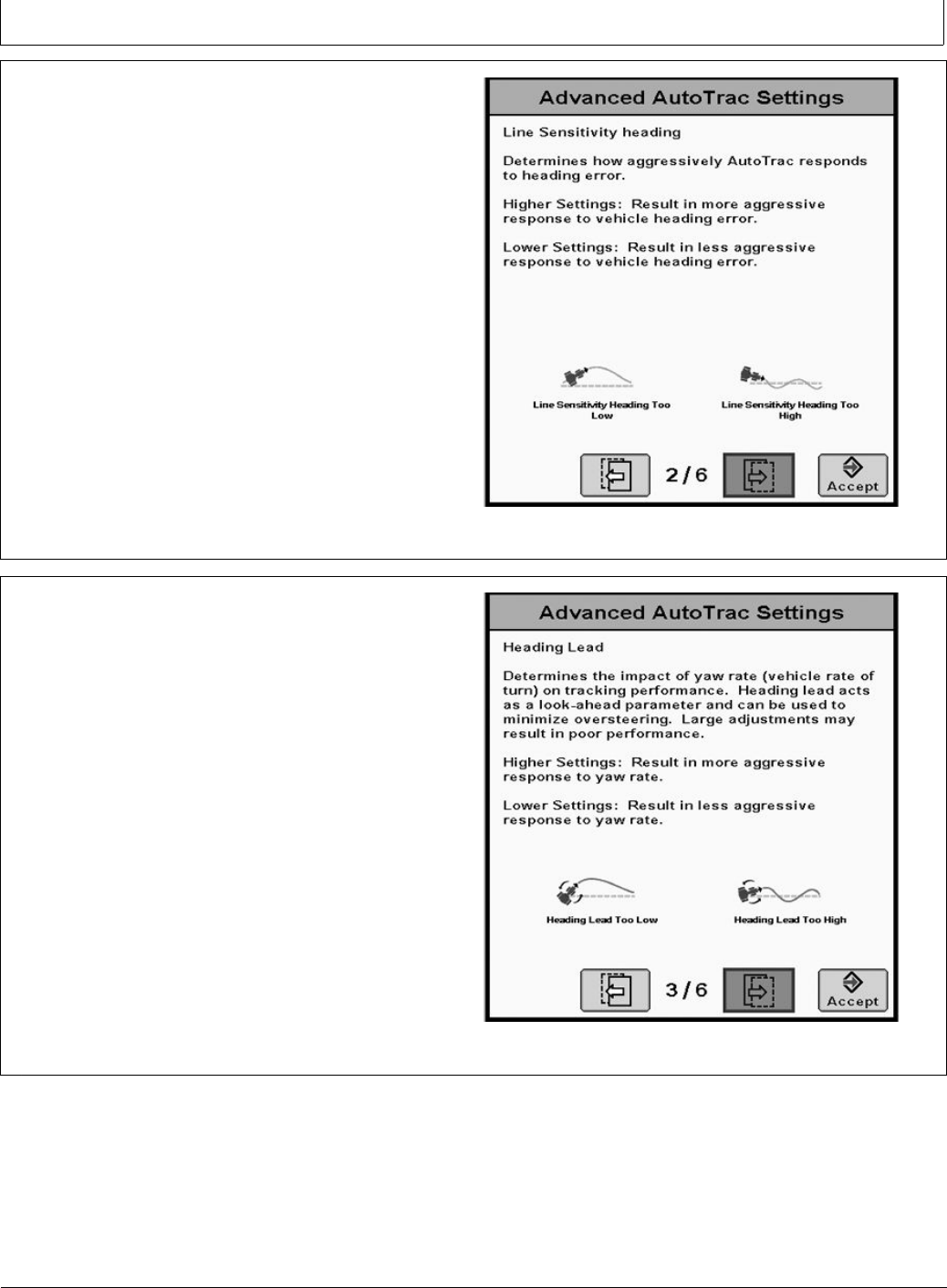
GS3 2630 Advanced Settings
CF86321,000027D -19-16MAY11-2/9
Continued on next page CF86321,000027D -19-16MAY11-3/9
Line Sensitivity Heading
Determines how aggressively AutoTrac responds to
heading errors.
Higher settings: Result in more aggressive response to
vehicle heading error.
Lower settings: Result in less aggressive response to
vehicle heading error.
PC13571 —UN—04MAY11
Line Sensitivity Heading
Heading Lead
Determines the impact of yaw rate (vehicle rate of turn)
on tracking performance. This can be thought of as a
look-ahead parameter. Large adjustments may result in
poor performance.
Higher settings: Results in more aggressive response
to vehicle twist.
Lower Settings: Results in less aggressive response to
vehicle twist.
PC13573 —UN—04MAY11
Heading Lead
45-5 090811
PN=59
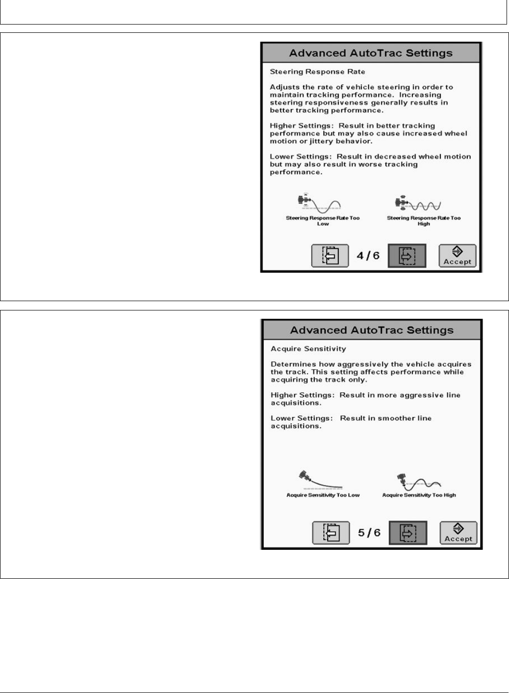
GS3 2630 Advanced Settings
CF86321,000027D -19-16MAY11-4/9
Continued on next page CF86321,000027D -19-16MAY11-5/9
Steering response Rate
Adjusts the rate of vehicle steering in order to maintain
tracking performance. Increasing steering responsiveness
generally results in better tracking performance.
Higher settings: Results in better tracking performance but
may also cause increased wheel motion or jittery behavior.
Lower Settings: Results in decreased wheel motion but
may also result in worse tracking performance.
PC13572 —UN—04MAY11
Steering Response Rate
Acquire Sensitivity
Determines how aggressively the vehicle acquires the
track. This setting affects performance while acquiring
the track only.
High settings: Results in a more aggressive track line
acquisition.
Lower settings: Results will give smoother entry into the
next track.
Step 1: Optimize Steering Response Rate
•Tune speed by operating parallel to and 1.2 m (4 ft) off
of the A-B Line.
•Activate AutoTrac Controller and observe performance.
•While tuning, adjust in increments of 10 between the
range of 50 to 200.
PC13574 —UN—04MAY11
Acquire Sensitivity
45-6 090811
PN=60
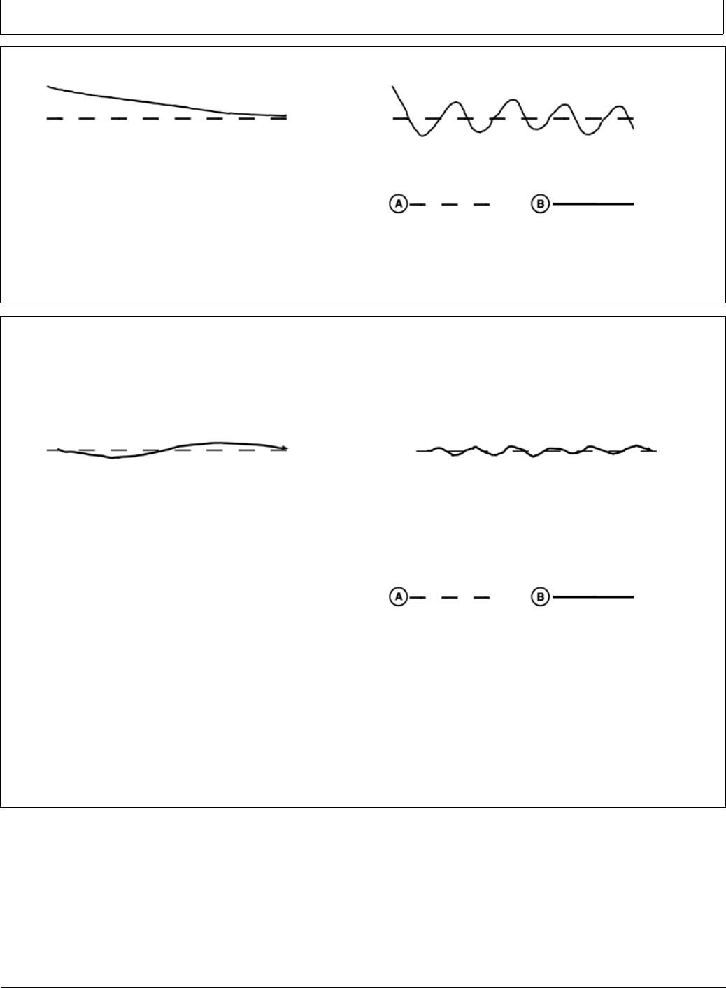
GS3 2630 Advanced Settings
CF86321,000027D -19-16MAY11-6/9
Continued on next page CF86321,000027D -19-16MAY11-7/9
Step 2: Optimize Acquire Sensitivity
PC8797 —UN—21FEB06
Acquire Sensitivity Too Low
PC8796 —UN—21FEB06
Acquire Sensitivity Too High
•Tune speed by operating parallel to and 1.2 m (4 ft) off
of the A-B Line.
•Activate AutoTrac Controller and observe performance.
•Tune Acquire Sensitivity until machine acquires the line
smoothly.
PC8999 —UN—08MAR06
A—Desired Track—Broken
Line
B—Actual Track—Solid Line
Step 3: Optimize Line Sensitivity
PC8794 —UN—08MAR06
Line Sensitivities Too Low
PC8795 —UN—08MAR06
Line Sensitivities Too High
A: Line Sensitivity—Tracking
•Tune line sensitivity tracking while operating on the
A-B line.
•If machine wanders too far from the A-B line adjust line
sensitivity—tracking higher.
•If machine becomes unstable around A-B line adjust
line sensitivity—tracking lower.
B: Line Sensitivity—Heading
•Tune line sensitivity heading while operating on the
A-B line.
•If the front of the machine wanders too far from the
track direction adjust line sensitivity—heading higher.
•If machine becomes unstable adjust line
sensitivity—heading lower.
PC8999 —UN—08MAR06
A—Desired Track—Broken
Line
B—Actual Track—Solid Line
NOTE: Line Sensitivities work together—If both are set too
high the vehicle will become unstable. If both are set
too low, the vehicle will wander around the A-B line.
45-7 090811
PN=61
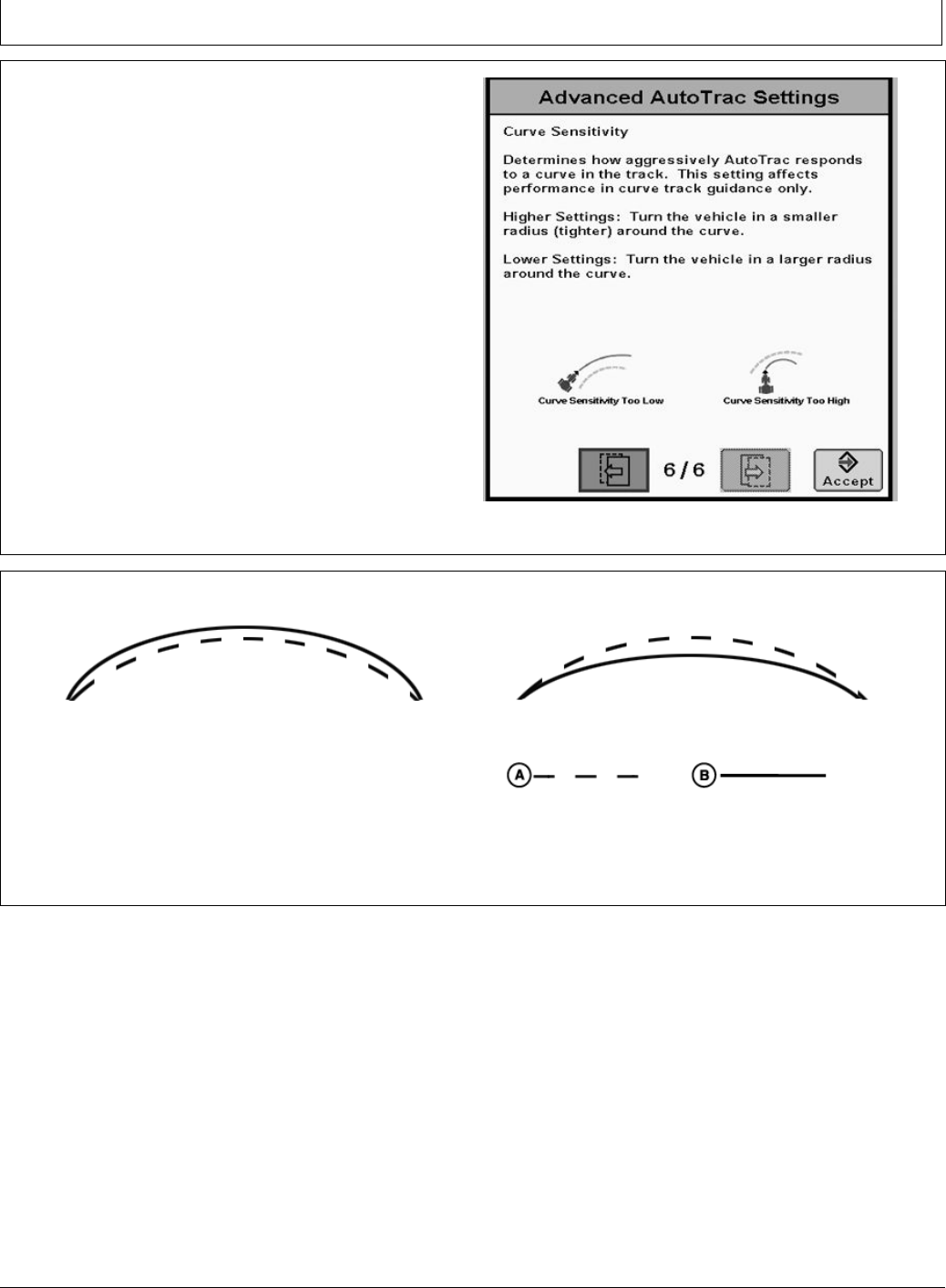
GS3 2630 Advanced Settings
CF86321,000027D -19-16MAY11-8/9
CF86321,000027D -19-16MAY11-9/9
Curve Sensitivity
Determines how aggressively AutoTrac responds to a
curve in the track. This setting affects performance in
curve track guidance only.
Higher settings: Turns the vehicle in a smaller radius
(tighter) around the curve.
Lower Settings: Turns the vehicle in a larger radius
around the curve.
PC13575 —UN—04MAY11
Curve Sensitivity
Curve Sensitivity
PC8944 —UN—21FEB06
Curve Sensitivity Too Low
PC8943 —UN—21FEB06
Curve Sensitivity Too High
•Tune Curve Sensitivity while operating in Curve Track
•If vehicle turns outside of the curve adjust sensitivity
higher
•If vehicle turns inside of the curve adjust sensitivity lower.
Find the combination of values that works best for the
vehicle.
PC8999 —UN—08MAR06
A—Desired Track—Broken
Line
B—Actual Track—Solid Line
45-8 090811
PN=62

GS3 2630 Advanced Settings
CF86321,000027E -19-16MAY11-1/1
CF86321,000027F -19-16MAY11-1/1
Tuning Tips, Tricks, and Precautions
•High Speed/Loose Soil Conditions
- Tip 1: The main goal with AutoTrac is to minimize
off-track error. In many conditions the best results are
obtained as the production system is currently tuned
with the default settings.
- Tip 2: It has been demonstrated through testing that
increased Heading Lead when operating at higher
speeds, greater than 11 km/h (7 mph), improves
AutoTrac stability.
- Tip 3: Loose soil has a tendency to decrease the
ability of the machine to steer when necessary,
thereby decreasing performance. To counteract this
issue increase the Line Sensitivity Heading.
Potential tradeoffs associated with increasing Line
Sensitivity Heading are:
1. In some conditions the increased Heading Lead
can lead to higher frequency instabilities.
2. Line Sensitivity Heading is used for line acquisitions
as well as tracking on line. Therefore, increasing Line
Sensitivity Heading can affect line acquisitions.
•When using AutoTrac to cross previous rows
- Tip 1: In these circumstances it is common to
experience excessive and repeatable side to side
motion. Increasing Line Sensitivity Heading and
Heading Lead can help reduce the vehicle motion.
- Tip 2: In extreme cases, Differential Lock may be
required in addition to the above tip to achieve
satisfactory performance.
NOTE: When increasing Line Sensitivity Heading and
Heading Lead, Line Sensitivity Tracking may need
to be reduced to prevent excessive wheel motion.
Troubleshooting
Symptom Problem Solution
AutoTrac controller unstable when
entering track
Acquire sensitivity too high Decrease acquire sensitivity
AutoTrac controller takes too long
to enter next track
Acquire sensitivity too low Increase acquire sensitivity
AutoTrac controller constantly
weaves in the row
StarFire Height or Fore-Aft not
properly set
Enter correct StarFire Height and
Fore-Aft dimension
Line sensitivities incorrect. Optimize line sensitivities (See
OPTIMIZING AUTOTRAC
UNIVERSAL PERFORMANCE
in Setup section.)
StarFire mount direction in SETUP
different from actual mount direction
Correctly match TCM SETUP mount
direction to actual mount direction
AutoTrac controller did not establish
direction correctly
Drive forward at a speed greater than
1.6 km/h (1 mph) and turn steering
wheel greater than 45 degrees in one
direction
Loose Soil Add Ballast (Follow recommended
machine specications)
AutoTrac Controller drives inside
curve
Curve Sensitivity too high Lower curve sensitivity
45-9 090811
PN=63
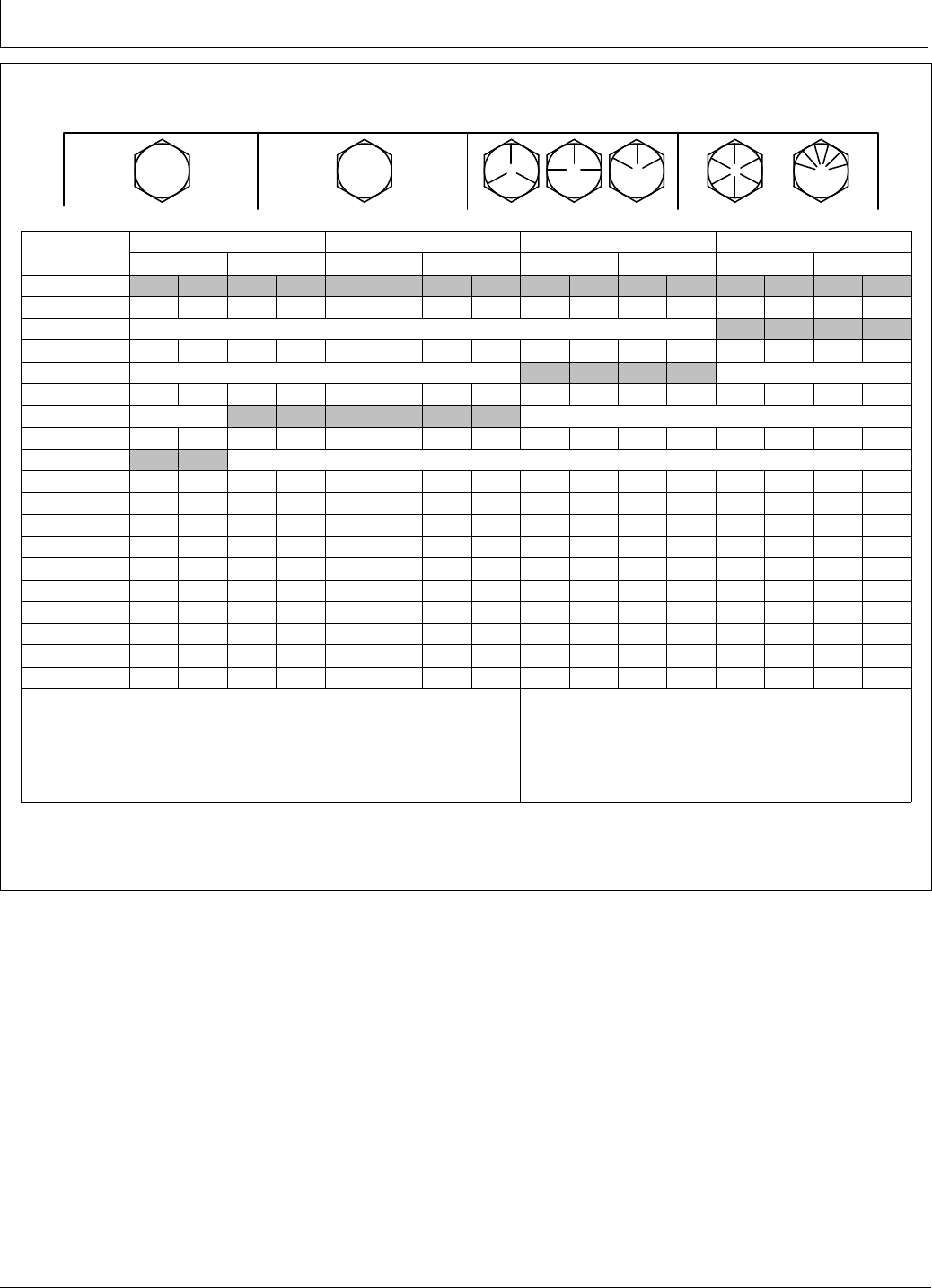
Specications
DX,TORQ1 -19-12JAN11-1/1
Unied Inch Bolt and Screw Torque Values
TS1671 —UN—01MAY03
SAE Grade 1 SAE Grade 2aSAE Grade 5, 5.1 or 5.2 SAE Grade 8 or 8.2
Bolt or Screw
Size LubricatedbDrycLubricatedbDrycLubricatedbDrycLubricatedbDryc
N·m lb.-in. N·m lb.-in. N·m lb.-in. N·m lb.-in. N·m lb.-in. N·m lb.-in. N·m lb.-in. N·m lb.-in.
1/4 3.7 33 4.7 42 6 53 7.5 66 9.5 84 12 106 13.5 120 17 150
N·m lb.-ft. N·m lb.-ft.
5/16 7.7 68 9.8 86 12 106 15.5 137 19.5 172 25 221 28 20.5 35 26
N·m lb.-ft. N·m lb.-ft.
3/8 13.5 120 17.5 155 22 194 27 240 35 26 44 32.5 49 36 63 46
N·m lb.-ft. N·m lb.-ft. N·m lb.-ft.
7/16 22 194 28 20.5 35 26 44 32.5 56 41 70 52 80 59 100 74
N·m lb.-ft.
1/2 34 25 42 31 53 39 67 49 85 63 110 80 120 88 155 115
9/16 48 35.5 60 45 76 56 95 70 125 92 155 115 175 130 220 165
5/8 67 49 85 63 105 77 135 100 170 125 215 160 240 175 305 225
3/4 120 88 150 110 190 140 240 175 300 220 380 280 425 315 540 400
7/8 190 140 240 175 190 140 240 175 490 360 615 455 690 510 870 640
1 285 210 360 265 285 210 360 265 730 540 920 680 1030 760 1300 960
1-1/8 400 300 510 375 400 300 510 375 910 670 1150 850 1450 1075 1850 1350
1-1/4 570 420 725 535 570 420 725 535 1280 945 1630 1200 2050 1500 2600 1920
1-3/8 750 550 950 700 750 550 950 700 1700 1250 2140 1580 2700 2000 3400 2500
1-1/2 990 730 1250 930 990 730 1250 930 2250 1650 2850 2100 3600 2650 4550 3350
Torque values listed are for general use only, based on the strength of the bolt
or screw. DO NOT use these values if a different torque value or tightening
procedure is given for a specic application. For plastic insert or crimped steel
type lock nuts, for stainless steel fasteners, or for nuts on U-bolts, see the
tightening instructions for the specic application. Shear bolts are designed to fail
under predetermined loads. Always replace shear bolts with identical grade.
Replace fasteners with the same or higher grade. If higher
grade fasteners are used, tighten these to the strength of the
original. Make sure fastener threads are clean and that you
properly start thread engagement. When possible, lubricate
plain or zinc plated fasteners other than lock nuts, wheel bolts
or wheel nuts, unless different instructions are given for the
specic application.
aGrade 2 applies for hex cap screws (not hex bolts) up to 6 in. (152 mm) long. Grade 1 applies for hex cap screws over 6
in. (152 mm) long, and for all other types of bolts and screws of any length.
b“Lubricated” means coated with a lubricant such as engine oil, fasteners with phosphate and oil coatings, or 7/8 in.
and larger fasteners with JDM F13C, F13F or F13J zinc ake coating.
c“Dry” means plain or zinc plated without any lubrication, or 1/4 to 3/4 in. fasteners with JDM F13B, F13E or F13H zinc ake coating.
50-1 090811
PN=64
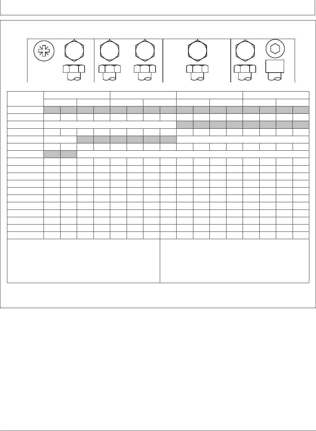
Specications
DX,TORQ2 -19-12JAN11-1/1
Metric Bolt and Screw Torque Values
TS1670 —UN—01MAY03
4.84.8 8.8 9.8 10.9 12.9 12.9
12.9
12.9
10.9
9.8
8.8
4.8
Class 4.8 Class 8.8 or 9.8 Class 10.9 Class 12.9
Bolt or Screw
Size LubricatedaDrybLubricatedaDrybLubricatedaDrybLubricatedaDryb
N·m lb.-in. N·m lb.-in. N·m lb.-in. N·m lb.-in. N·m lb.-in. N·m lb.-in. N·m lb.-in. N·m lb.-in.
M6 4.7 42 6 53 8.9 79 11.3 100 13 115 16.5 146 15.5 137 19.5 172
N·m lb.-ft. N·m lb.-ft. N·m lb.-ft. N·m lb.-ft.
M8 11.5 102 14.5 128 22 194 27.5 243 32 23.5 40 29.5 37 27.5 47 35
N·m lb.-ft. N·m lb.-ft. N·m lb.-ft.
M10 23 204 29 21 43 32 55 40 63 46 80 59 75 55 95 70
N·m lb.-ft.
M12 40 29.5 50 37 75 55 95 70 110 80 140 105 130 95 165 120
M14 63 46 80 59 120 88 150 110 175 130 220 165 205 150 260 190
M16 100 74 125 92 190 140 240 175 275 200 350 255 320 235 400 300
M18 135 100 170 125 265 195 330 245 375 275 475 350 440 325 560 410
M20 190 140 245 180 375 275 475 350 530 390 675 500 625 460 790 580
M22 265 195 330 245 510 375 650 480 725 535 920 680 850 625 1080 800
M24 330 245 425 315 650 480 820 600 920 680 1150 850 1080 800 1350 1000
M27 490 360 625 460 950 700 1200 885 1350 1000 1700 1250 1580 1160 2000 1475
M30 660 490 850 625 1290 950 1630 1200 1850 1350 2300 1700 2140 1580 2700 2000
M33 900 665 1150 850 1750 1300 2200 1625 2500 1850 3150 2325 2900 2150 3700 2730
M36 1150 850 1450 1075 2250 1650 2850 2100 3200 2350 4050 3000 3750 2770 4750 3500
Torque values listed are for general use only, based on the strength of
the bolt or screw. DO NOT use these values if a different torque value or
tightening procedure is given for a specic application. For stainless steel
fasteners or for nuts on U-bolts, see the tightening instructions for the
specic application. Tighten plastic insert or crimped steel type lock nuts
by turning the nut to the dry torque shown in the chart, unless different
instructions are given for the specic application.
Shear bolts are designed to fail under predetermined loads. Always
replace shear bolts with identical property class. Replace fasteners with
the same or higher property class. If higher property class fasteners are
used, tighten these to the strength of the original. Make sure fastener
threads are clean and that you properly start thread engagement. When
possible, lubricate plain or zinc plated fasteners other than lock nuts,
wheel bolts or wheel nuts, unless different instructions are given for the
specic application.
a“Lubricated” means coated with a lubricant such as engine oil, fasteners with phosphate and oil coatings, or M20
and larger fasteners with JDM F13C, F13F or F13J zinc ake coating.
b“Dry” means plain or zinc plated without any lubrication, or M6 to M18 fasteners with JDM F13B, F13E or F13H zinc ake coating.
50-2 090811
PN=65
Specications
BA31779,0000249 -19-01AUG11-1/1
EC Declaration of Conformity
Deere & Company
Moline, Illinois U.S.A.
The person named below declares that
Product: AutoTrac™ Controller
fullls all relevant provisions and essential requirements of the following directives:
Directive Number Certication Method
Electromagnetic Compatibility Directive 2004/108/EC Self certied, per Annex II of the Directive
Name and address of the person in the European Community authorized to compile the technical construction le:
Brigitte Birk
Deere & Company European Ofce
John Deere Strasse 70
Mannheim, Germany D-68163
EUConformity@JohnDeere.com
Place of declaration: Kaiserslautern, Germany Name: Aaron Senneff
Date of declaration: 29 July 2011 Title: Engineering Manager, John Deere Intelligent Solutions
Group
Manufacturing unit: John Deere Intelligent Solutions Group
DXCE01 —UN—28APR09
50-3 090811
PN=66

Index
Page
A
Acquire Sensitivity ...................................................... 45-6
Acquired Sensitivity .................................................... 40-4
Addresses
Diagnostics .................................................... 35-1, 35-5
Advanced Settings...................................................... 45-5
Acquire Sensitivity................................................... 45-6
Curve Sensitivity ..................................................... 45-8
Heading Lead.......................................................... 45-5
Line Sensitivity Tracking ......................................... 45-4
Optimizing AutoTrac Controller Performance ......... 45-4
Steering Response Rate......................................... 45-6
AutoTrac
Activating System .......................................... 30-1, 40-3
Deactivate...................................................... 30-8, 40-3
Enabling System............................................ 30-1, 40-2
Tractor
Conditions for Activation...................................... 25-9
AutoTrac Accuracy ..................................................... 15-1
AutoTrac Controller
calibrate the SID (steering input device) ................. 25-3
Calibration............................................................... 25-1
General Information ................................................ 15-1
Kit Type ................................................................... 25-3
Machine Type.......................................................... 25-3
Troubleshooting ...................................................... 20-1
WAS Calibration...................................................... 25-5
B
Bolt and screw torque values
Metric ...................................................................... 50-2
Unied inch ............................................................. 50-1
C
Calibration
AutoTrac Controller................................................. 25-1
Curve Sensitivity................................................ 40-4, 45-8
D
Deactivating
AutoTrac ................................................................. 40-3
Deactivating AutoTrac ................................................ 30-8
Diagnostic Addresses................................................. 35-5
Diagnostic Readings
AutoTrac Controller................................................. 20-2
Diagnostics
Addresses...................................................... 35-1, 35-5
AutoTrac ................................................................. 35-3
GPS ........................................................................ 35-3
Steering Controller .................................................. 35-3
Trouble Codes .................................. 25-10, 25-12, 35-1
Page
G
Guidance
Warnings................................................................. 35-3
H
Hardware torque values
Metric ...................................................................... 50-2
Unied inch ............................................................. 50-1
Heading Lead ............................................................. 45-5
L
Line Sensitivity
Heading................................................................... 40-4
Tracking .................................................................. 40-4
Line Sensitivity Heading ............................................. 45-5
Line Sensitivity Tracking............................................. 45-4
M
Master Switch.................................................... 30-8, 40-3
Metric bolt and screw torque values ........................... 50-2
O
Operation (AutoTrac Controller)
Activity Monitor........................................................ 15-2
AutoTrac Settings ................................................... 15-2
Operator Detection Timeout.................................... 15-2
Operator Presense ..................................................... 40-4
R
Raven ......................................................................... 25-1
Recommended Tuning Settings ................................. 45-3
S
StarFire Fore-Aft......................................................... 40-4
StarFire Height ........................................................... 40-4
StarFire Setup .......................................................... 30-16
Steer Asymmetry ........................................................ 40-4
Steer Play ................................................................... 40-4
Steer Wheel Speed .................................................... 40-4
Steering Response Rate ............................................ 45-6
T
Torque charts
Metric ...................................................................... 50-2
Unied inch ............................................................. 50-1
Tractor
AutoTrac
Conditions for Activation...................................... 25-9
Continued on next page
Index-1 090811
PN=1

Index
Page
Trouble Codes ...................................... 25-10, 25-12, 35-1
Troubleshooting
AutoTrac ................................................................. 35-3
AutoTrac Universal ................................................. 20-1
Diagnostic Addresses .................................... 35-1, 35-5
GPS ........................................................................ 35-3
Steering Controller .................................................. 35-3
Trouble Codes .................................. 25-10, 25-12, 35-1
Troubleshooting (AutoTrac Controller)
Stop Codes ............................................................. 20-3
Tuning Recommendations.......................................... 45-1
Tuning Tips, Tricks, and Precautions.......................... 45-9
U
Unied inch bolt and screw torque values .................. 50-1
V
Vehicle Type ............................................................... 40-4
W
WAS Calibration ......................................................... 25-5
Index-2 090811
PN=2
John Deere Service Literature Available
DX,SERVLIT -19-31JUL03-1/1
Technical Information
Technical information can be purchased from John Deere.
Some of this information is available in electronic media,
such as CD-ROM disks, and in printed form. There are
many ways to order. Contact your John Deere dealer.
Call 1-800-522-7448 to order using a credit card. Search
online from http://www.JohnDeere.com. Please have
available the model number, serial number, and name of
the product.
Available information includes:
•PARTS CATALOGS list service parts available for your
machine with exploded view illustrations to help you
identify the correct parts. It is also useful in assembling
and disassembling.
•OPERATOR’S MANUALS providing safety, operating,
maintenance, and service information. These manuals
and safety signs on your machine may also be available
in other languages.
•OPERATOR’S VIDEO TAPES showing highlights of
safety, operating, maintenance, and service information.
These tapes may be available in multiple languages
and formats.
•TECHNICAL MANUALS outlining service information
for your machine. Included are specications, illustrated
assembly and disassembly procedures, hydraulic oil
ow diagrams, and wiring diagrams. Some products
have separate manuals for repair and diagnostic
information. Some components, such as engines, are
available in separate component technical manuals
•FUNDAMENTAL MANUALS detailing basic information
regardless of manufacturer:
- Agricultural Primer series covers technology in farming
and ranching, featuring subjects like computers, the
Internet, and precision farming.
- Farm Business Management series examines
“real-world” problems and offers practical solutions
in the areas of marketing, nancing, equipment
selection, and compliance.
- Fundamentals of Services manuals show you how to
repair and maintain off-road equipment.
- Fundamentals of Machine Operation manuals
explain machine capacities and adjustments, how to
improve machine performance, and how to eliminate
unnecessary eld operations.
TS189 —UN—17JAN89TS191 —UN—02DEC88TS224 —UN—17JAN89TS1663 —UN—10OCT97
SLIT-1 090811
PN=69


John Deere Service Keeps You On Job
DX,IBC,2 -19-02APR02-1/1
John Deere Is At Your Service
CUSTOMER SATISFACTION is important to John Deere.
Our dealers strive to provide you with prompt, efcient
parts and service:
–Maintenance and service parts to support your
equipment.
–Trained service technicians and the necessary diagnostic
and repair tools to service your equipment.
CUSTOMER SATISFACTION PROBLEM RESOLUTION
PROCESS
Your John Deere dealer is dedicated to supporting your
equipment and resolving any problem you may experience.
1. When contacting your dealer, be prepared with the
following information:
–Machine model and product identication number
–Date of purchase
–Nature of problem
TS201 —UN—23AUG88
2. Discuss problem with dealer service manager.
3. If unable to resolve, explain problem to dealership
manager and request assistance.
4. If you have a persistent problem your dealership is
unable to resolve, ask your dealer to contact John Deere
for assistance. Or contact the Ag Customer Assistance
Center at 1-866-99DEERE (866-993-3373) or e-mail us at
www.deere.com/en_US/ag/contactus/.
IBC-1 090811
PN=71