Johnson Controls Interiors MS-BTCVT-0 Bluetooth Radio User Manual 24101082
Johnson Controls Interiors L.L.C. Bluetooth Radio 24101082
Manual

Converter with Bluetooth® Wireless Technology (BTCVT) Installation
Instructions 1
this information may change
Applications
The Converter with Bluetooth® wireless technology
(BTCVT) is a communications converter that provides
a temporary connection between AIM software and a
field device to commission, synchronize, and balance
Metasys® system extended architecture hardware
controllers.
The BTCVT provides communication from the Field
Controller (FC) bus or the Sensor and Actuator (SA)
bus to a Bluetooth wireless technology enabled device,
such as a laptop computer. The BTCVT converts
Master Slave Token Passing (MSTP) protocol to
2.4 GHz Bluetooth wireless communication and from
wireless communication back to MSTP.
A strap, provided with the BTCVT, allows you to hang
the BTCVT next to the contoller while the wireless
connection allows you to be up to 10 m (33 ft) away
while you commission the controller with a laptop
computer.
The BTCVT is compatible with the following MSTP
devices:
• Field Equipment Controller (FEC)
• Variable Air Volume Modular Assembly (VMA)
• Input/Output Module (IOM)
• Network Sensors
The BTCVT uses Bluetooth wireless technology, but is
not compatible with other Bluetooth wireless devices.
Only use the BTCVT with the wireless card supplied
with the BTCVT or a wireless processor.
Installation
Observe the following guidelines and see the Mounting
section in this document.
• Verify that all parts are shipped with the BTCVT.
• The blue protective boot minimizes shock damage
to the BTCVT. If removed from the protective boot,
the BTCVT is prone to physical damage.
Parts Included
•one BTCVT
• one 3Com® Bluetooth PC card and vendor-
supplied software
• one 5-ft retractable cable
• one set of Installation Instructions
• one hanging strap with internal magnet
Special Tools Needed
The BTCVT provides a wireless link to the controller.
To access the BTCVT, you need the following:
• laptop Computer running Microsoft®
Windows® 2000 Professional operating system or
later with the wireless card installed.
• AIM software
IMPORTANT: Magnetic fields can cause damage to
magnetic storage media, including cassette tapes,
floppy disks, credit cards, and video tapes. Keep all
magnets away from all types of magnetic media.
Converter with Bluetooth® Wireless Technology (BTCVT)
Installation Instructions
MS-BTCVT-0 Part No. 24-10108-2
Rev. —
Issued February 1, 2005

Converter with Bluetooth® Wireless Technology (BTCVT) Installation Instructions2
this information may change
Dimensions
Accessories
Mounting
Mounting Location Considerations
Observe the following guidelines when mounting an
BTCVT:
• Always hang the BTCVT using the strap provided.
Note: Use the strap loop to hang the BTCVT or
attach the strap magnet to a metal object (such as
a metal pipe).
• Mount the Converter in areas free of corrosive
vapors and observe the environmental limitations
listed in the Technical Specifications section of this
document.
• Objects (including ductwork, cabinets, doors, and
glass) can impede the wireless signal. Minimize
the amount of objects between the laptop computer
and the BTCVT. Use line-of-sight, if possible.
Wiring
Wiring Consideration and Guidelines
Observe the following guidelines when wiring the
BTCVT:
• Do not allow the BTCVT to hang from the cable
connection. Always use the strap provided to hang
the BTCVT.
• Provide some slack in the cable between the
BTCVT and the controller.
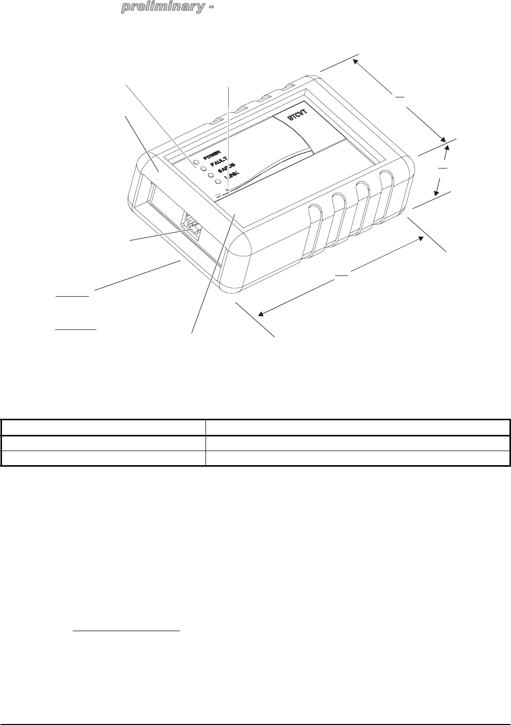
Figure 1: Front of the BTCVT, Dimensions (mm/in.) and Other Physical Features
Status LEDs
Protective PVC Boot
SA/FC Bus
(6-Pin RS-485 Port)
Upgrade Firmware Button
(Not Currently Employed)
Do Not Push
35
1.4
75
2.9
116
4.6
btcvt-iso
On Back:
Fold-out Kickstand
Hanging Strap Attachment Point
Not Shown:
Hanging Strap
MAC Address
On Labelt
Table 1: Products and Accessories (Order Separately)
Code Number Description
MS-BTCVT-0 Converter with Bluetooth Wireless Technology
<??> Cable replacement set; includes one 5-ft retractable cable

Converter with Bluetooth® Wireless Technology (BTCVT) Installation Instructions 3
this information may change
Power Supply, Network, and
Communication Connections
See Figure 1 for the location of the
communications terminal on the BTCVT.
SA/FC Port
The SA/FC Port on the BTCVT is a
6-pin RS-485 port designed to connect
the BTCVT to an accessible SA or FC
port on an MSTP device using the cable
assembly provided. The SA/FC is a
straight through, 1-to-1connection (not a cross-over).
The maximum allowable cable length is 100 ft.
Do not plug the SA/FC Port into a standard phone jack.
Wiring the Converter
Observe the following guidelines and procedures when
wiring the BTCVT.
To wire the network communication connections and
supply power:
1. After securely hanging the BTCVT, connect one
male end of the supplied cable to the BTCVT.
2. Connect the the other end of the cable to the
controller.
Note: The BTCVT has a dedicated MSTP bus
address of 01. Only one BTCVT can be connected to
the MSTP bus per physical trunk on the system.
Setup and Adjustments
The BTCVT device itself requires no commissioning.
Installing the Bluetooth wireless technology
enabled wireless card.
To install the wireless card:
1. Use your Web browser, navigate to http://
www.3com.com/products/en_US/
result.jsp?selected=5&sort=effdt&sku=3CRWB6096
B&order=desc
Note: Alternatively, search the available
downloads for product number 3CRWB6096B for
the file called 3crwb6096b1_2_10en.exe.
2. Open the file and follow the onscreen instructions
to Extract the drivers and software.
3. When Bluetooth product selection dialog box
appears, select the PC Card option. The 3Com
Wireless Installer dialog box appears.
4. Click on Install Bluetooth Product. The Bluetooth
Setup dialog box appears and looks for your
wireless card.
5. Insert (or reinsert) the wireless card into your
computer. The Bluetooth Setup dialog box changes
to say Please wait. Do not click close.
The InstallShield Wizard appears.
6. Follow the onscreen instructions until the Bluetooth
Connection Manager appears.
You may now close all open windows.
Setting Up the BTCVT in the Bluetooth
Connection Manager
Once you have installed the Bluetooth wireless card
hardware and software, you can set up the BTCVT
within the Bluetooth Connection Manager.
This procedure allows the laptop to identify the BTCVT
once it is within range and speeds the connection
between the BTCVT and AIM software.
Note: You only need to set this up once per BTCVT.
To set up the BTCVT in the Bluetooth Connection
Manager:
1. Plug the BTCVT into an MSTP device.
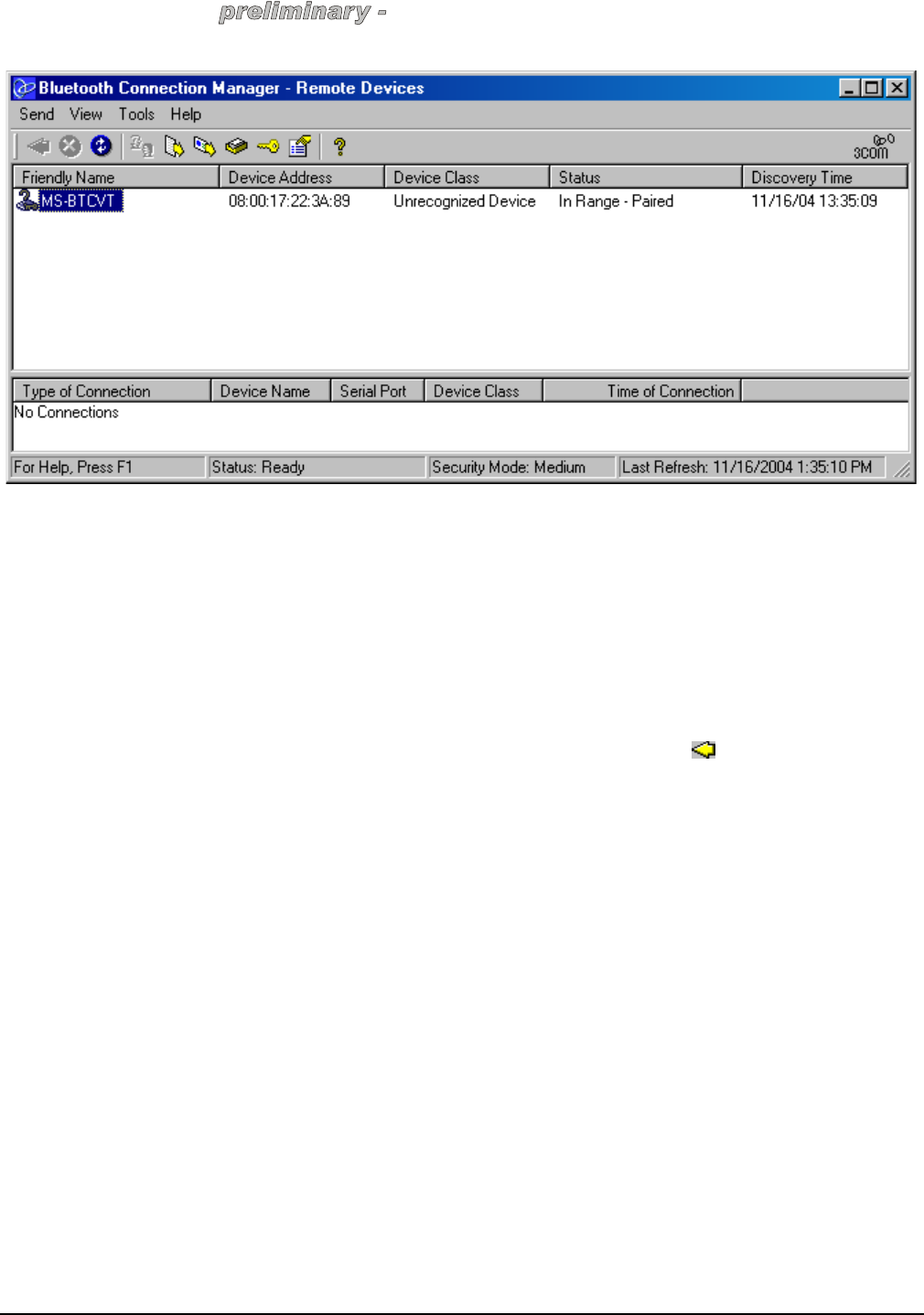
2. Double-click the 3Com Bluetooth Connection
Manager icon in the system tray. The Bluetooth
Connection Manager appears showing MS-BTCVT
in the Friendly Name column.
Table 2: SA/FC Port Pin Designations
Pin Number
(Both Ends of
Cable)
Signal Name
1(FC or SA) +
2(FC or SA) -
315 VDC Common
415 VDC Hot
5No Connection
6No Connection
6 16 1
. . . .
6-pin
IMPORTANT: We recommend that you install the
latest version of the wireless card software from the
vendor’s Website.

Converter with Bluetooth® Wireless Technology (BTCVT) Installation Instructions4
this information may change
Note: If the icon is red, the wireless card is not
installed correctly. Refer to the installation instructions
provided with the wireless card.
3. Compare the BTCVT’s device address in the
Connection Manager to the MAC address printed
on the label of the BTCVT. They should match.
Note: If multiple devices appear in the window, there
are other Bluetooth devices in range. Be sure to set up
the device with the device address that matches the
BTCVT’s printed label.
4. Highlight the BTCVT and select Tools > COM
Ports. The Bluetooth COM Ports dialog box
appears.
5. Highlight 3Com Bluetooth Serial Client (your
COM port number) and click Edit. The Edit COM
Port dialog box appears.
6. Select Select Now and click OK.
7. Close the Bluetooth COM Ports dialog box.
8. Double-click MS-BTCVT. The Authentication dialog
box appears.
9. Type BTCVT and click OK. The Bluetooth
Connection Manager - MS-BTCVT dialog box
appears with the following fields Serial Port -
Emulated serial cable connection.
10. Click the yellow arrow . The Status field reads In
Range - Paired (Figure 2).
The Bluetooth wireless card is now ready to
communicate to the BTCVT using AIM software.
Commissioning the Laptop Computer
The HyperTerminal program, provided with the
Windows OS, provides a link between the BTCVT and
the computer.
Figure 2: Bluetooth Connection Manager

Converter with Bluetooth® Wireless Technology (BTCVT) Installation Instructions 5
this information may change
Operation
Connecting the BTCVT to the System
<where on the system??>
Establishing a Connection between the BTCVT and
AIM Software
The connection between the BTCVT and AIM software
is handled by the AIM software once you have set up
the correct COM Port setting in the AIM software. Refer
to the AIM Software Help for details.
You can speed up the BTCVT and AIM software
connection process by setting up the BTCVT in the
Bluetooth Connection Manager. Refer to Setting Up the
BTCVT in the Bluetooth Connection Manager.
Troubleshooting
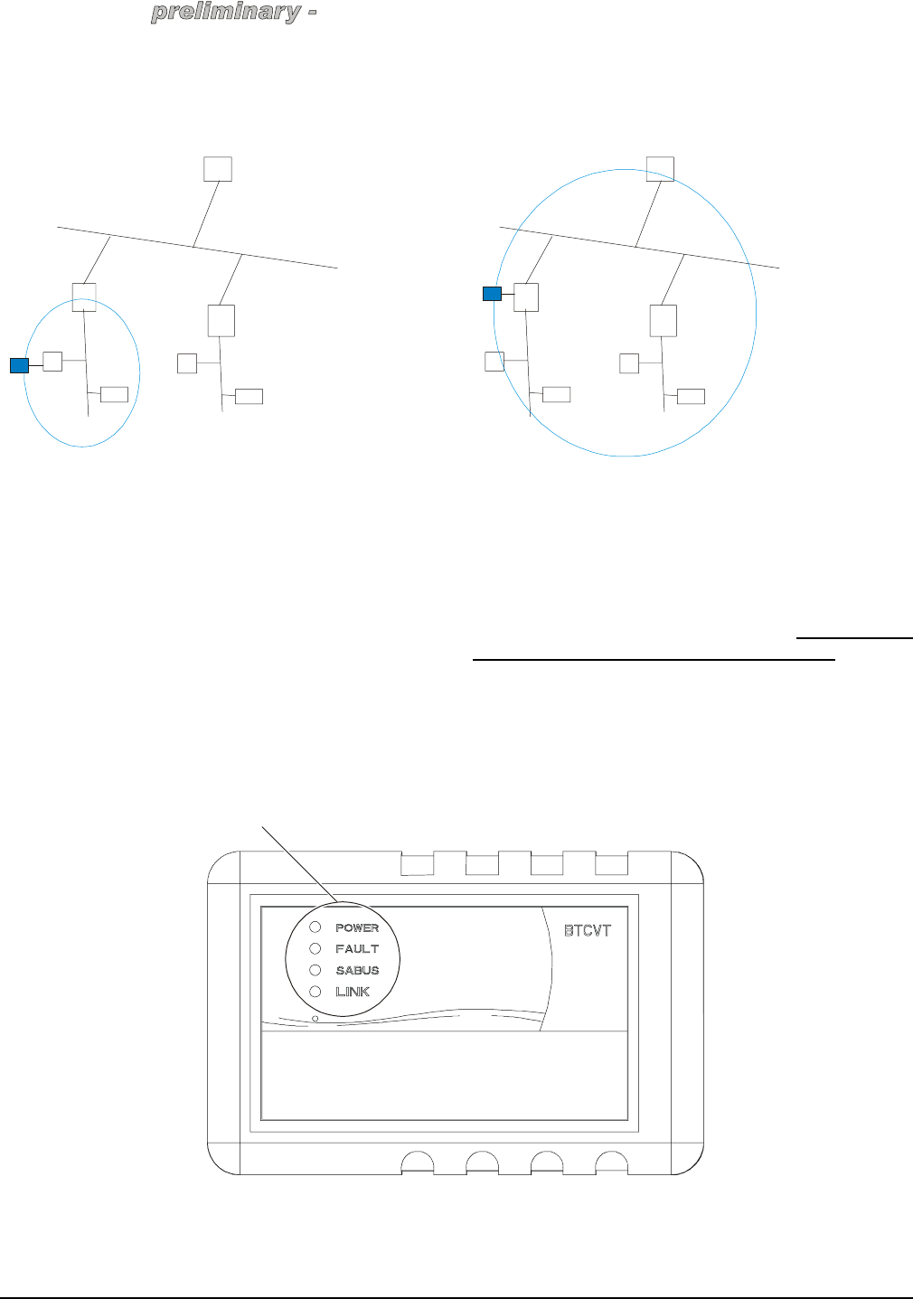
Status Indication LEDs
The Converter has 4 LEDs to indicate power and
communication status. Figure 4 shows the LEDs and
Table 3 describes their function.
Figure 3: Connecting a BTCVT to an MSTP Topology Example
mstp_topology
Figure 4: Front of BTCVT with LED Designations
Status LEDs
btcvt-front

Converter with Bluetooth® Wireless Technology (BTCVT) Installation Instructions6
this information may change
LED Test Sequence at Startup
During startup, the Converter automatically initiates an
LED test to verify the operational status of the LEDs.
Immediately after connecting supply power, the
following LED lighting sequence occurs:
1. All LEDs light up.
2. The Power LED remains lit while all other LEDs go
to Normal operation as indicated in Table 3.
Testing the Wireless Connection to the BTCVT
You can test the connection between the laptop and
the BTCVT using HyperTerminal software provided
with your Microsoft Windows OS software.
To test the wireless connection to the BTCVT:
1. From the Control Panel, navigate to System >
Hardware > Device Manager > Ports.
2. Double-click 3Com Bluetooth Serial Client
(COM port you are using). The Properties dialog
box appears.
3. On the Port Settings tab, select 115200 in the Bits
per second drop-down list and click OK.
4. On Start menu, select Programs > Accessories >
Communications > HyperTerminal. The
HyperTerminal program opens.
5. Type a name in the name field and click OK. The
Connect To dialog box appears.
6. Select the COM port you are using in the Connect
using drop-down list and click OK. The
HyperTerminal attempts to connect to the BTCVT.
If the BTCVT’s blue Link LED lights, the test was
successful.
After approximately four seconds, the BTCVT
disconnects from the HyperTerminal program and
the LED turns off.
7. Close the HyperTerminal program without saving
changes.
Repairs and Replacement
Do not remove the blue protective boot or open the
Converter housing. The Converter has no
user-serviceable parts inside.
The BTCVT requires no periodic field maintenance.
Table 3: Converter LED Designations and Descriptions
Color LED Name Normal Descriptions/Other Conditions
Green Power On Steady On Steady = Power is Supplied by Primary Voltage
Off = No Power
Red Fault Off Off Steady = No Faults
On Steady = Device Fault
Green SA/FC Bus Flicker Flicker = Data Transmission
Off Steady = No Data Transmission
Blue Link On On Steady = Bluetooth communication link established
Off Steady = Bluetooth communication link not established

Converter with Bluetooth® Wireless Technology (BTCVT) Installation Instructions 7
this information may change
Technical Specifications
Product Code MS-BTCVT-0 Converter with Bluetooth Wireless Technology
Power Requirement Nominal 15 VDC, provided through the SA/FC Port
Power Consumption 1.35 Watts maximum
Ambient Operating
Temperature 0° to 50° C (32° to 122° F)
Ambient Operating Conditions 5 to 95% RH, Noncondensing, 30° C (86° F) Maximum Dewpoint
Ambient Storage Temperature -40° to 85° C (-40° to 185° F)
Ambient Storage Conditions 5 to 95% RH, Noncondensing
Transmission Power 2.5 mW maximum
Transmission Speed Wireless Communication
115.2k bits per second (bps)
Serial Communication (SA/FC Bus)
9600, 19.2k, 38.4k, or 76.8k bps
Transmission Range (Typical) Wireless Communication
10 m (33 ft) line-of-sight
Wireless Security Security Mode 3 - Link Level Enforced Security
Network and Serial Interfaces Bluetooth Wireless Technology
One RS-485 Bus
Dimensions 116 x 75 x 35 mm (4.6 x 3.0 x 1.4 in.)
Housing Black Plastic Housing
Blue Protective Boot
Weight 0.165 kg (0.365 lb) without hanging components
Agency Listings United States FCC Title 47 - Telecommunications
Transmitter Complies with FCC part 15.247
Regulations for Low Power Unlicensed Transmitters (Transmitter
FCC Identification: <??>)
Receiver Complies with FCC part 15.109
Regulations for Low Power Unlicensed Receivers (Transmitter FCC
Identification: <??>)
Canada Industry Canada
Transmitter RSS-210
Receiver RSS-210
Europe European Commission driven by Directives
Transmitter - RTTE Directive 1995/5/EC
Test Standard is ETSI EN 300 328 ISM Spread Spectrum 2.4 GHz
Transmitter / Receiver - EMC Directive 89/336/EEC
Test Standard is ETSI EN 300 328 ISM Spread Spectrum 2.4 GHz
Japan Telecommunications Certification
The performance specifications are nominal and conform to acceptable industry standard. For application at conditions beyond these
specifications, consult the local Johnson Controls office. Johnson Controls, Inc. shall not be liable for damages resulting from misapplication
or misuse of its products.
FCC RADIO FREQUENCY EXPOSURE NOTICE
CAUTION: FCC Radio-Frequency Exposure Notice
This device generates and radiates radio-frequency energy. In order to comply with FCC radio-frequency radiation exposure guidelines for an uncontrolled
environment, this equipment has to be installed and operated while maintaining a minimum body to antenna distance of 2.5 cm (1.0 inch). This product does not
contain any user serviceable components. Any unauthorized product changes or modifications will invalidate 3Com’s warranty and all applicable
regulatory certifications and approvals.

Published in U.S.A. www.johnsoncontrols.com
Converter with Bluetooth® Wireless Technology (BTCVT) Installation Instructions8
Metasys® is a registered trademark of Johnson Controls, Inc.
All other marks herein are the marks of their respective owners.
© 2004 Johnson Controls, Inc.
Controls Group
507 E. Michigan Street
Milwaukee, WI 53202
this information may change
FCC PART 15 NOTICE (APPLICABLE TO USE WITHIN THE USA)
This device complies with part 15 of the FCC Rules. Operation is subject to the following two conditions: (1) This device may not cause
harmful interference, and (2) this device must accept any interference received, including interference that may cause undersired operation.
WARNING: This equipment has been tested and found to comply with the limits for a Class B digital device as applicable, pursuant to Part 15
of the FCC Rules. These limits are designed to provide reasonable protection against harmful interference in a residential installation. This
equipment generates, uses and can radiate radio frequency energy and, if not installed and used in accordance with the instructions, may
cause harmful interference to radio communications. However, there is no guarantee that interference will not occur in a particular
installation. If this equipment does cause harmful interference to radio or television reception, which can be determined by turning the
equipment off and on, the user is encouraged to try to correct the interference by one or more of the following measures:
– Reorient or relocate the receiving antenna.
– Increase the separation between the equipment and receiver.
– Connect the equipment into an outlet on a circuit different from that to which the receiver is connected.
– Consult the dealer or an experienced radio/TV technician for help.
The user may find the following booklet prepared by the Federal Communications Commission helpful:The Interference Handbook This
booklet is available from the U.S. Government Printing Office, Washington, D.C. 20402. Stock No. 004-000-00345-4.
WARNING: Changes or modifications not expressly approved by the party responsible for the compliance could void the user’s authority to
operate the equipment.
MANUFACTURER’S DECLARATION OF CONFORMITY
Johnson Controls, Inc.
Controls Group
507 E. Michigan St.
Milwaukee, WI 53202
Declares that the Product:
Date: 1 February, 2004
Brand Name: Johnson Controls, Inc.
Model Number: MS-BTCVT-0
Equipment Type: Converter with Bluetooth Wireless Technology
Complies with Part 15 of the FCC rules. Operation is subject to the following two conditions: (1) this device may not cause harmful
interference, and (2) this device must accept any interference received, including interference that may cause undesired operation.
INDUSTRY CANADA NOTICE (APPLICABLE FOR USE WITHIN CANADA)
IC: xxxxx-yyyyyyyyy
The term “IC” before the certification/registration number only signifies that the Industry Canada specifications were met.
To prevent radio interference to the licensed service, this device is intended to be operated indoors and away from windows to provide
maximum shielding. Equipment (or its transmit antenna) that is installed outdoors is subject to licensing. The installer of this radio equipment
must ensure that the antenna is located or pointed such that it does not emit RF field in excess of Health Canada limits for the general
population; consult Safety Code 6, obtainable from Health Canada’s website
www.hc-sc.gc.ca/rpb.
EUROPEAN COMMUNITY CE NOTICE
Marking by the symbol indicates compliance of this equipment to the R&TTE Directive 1999/5/EC. Such marking is indicative that this
equipment meets or exceeds the following technical standards:
– ETS 300 328 — Electromagnetic compatibility and Radio spectrum Matters (ERM); Wideband Transmission systems; data transmission equipment
operating in the 2,4GHz ISM band and using spread spectrum modulation techniques
– ETS 301 489-17— Electromagnetic compatibility and Radio spectrum Matters (ERM); Electromagnetic Compatibility (EMC) standard for radio equipment
and services; specific coniditions for Wideband data and High PErformance Radio Local Area Network (HIPERLAN) equipment
– EN 60950 — Safety of information technology equipment, including electrical business equipment
This device may be used throughout the European Community.