Johnson Controls Interiors TMPSENS2400A Temperature Sensor User Manual Manual
Johnson Controls Interiors L.L.C. Temperature Sensor Manual
Manual

Installation Instructions WRS-TTx Series
Issue Date June 13, 2005
© 2005 Johnson Controls, Inc. 1
Part No. 24-xxxx-xx, Rev. - www.johnsoncontrols.com
WRS-TTx Series Radio Frequency (RF)
Wireless Transmitters
Applications
The WRS-TTx Series Wireless Room Temperature
Transmitters are designed to report temperature
and set point (certain models) to a suitable JCI data
receiver. They can be used in two separate types
of control systems, depending on the application.
FCC and Industry Canada Compliance
Compliance Statement (Part 15.19)
This device complies with Part 15 of the FCC Rules.
Operation is subject to the following two conditions:
1. This device may not cause harmful
interference, and
2. This device must accept any interference
received, including interference that may
cause undesired operation.
Warning (Part 15.21)
Changes or modifications not expressly approved by
the party responsible for compliance could void the
user’s authority to operate the equipment.
To comply with FCC’s RF exposure limits for general population
/ uncontrolled exposure, the antenna(s) used for this transmitter
must be installed to provide a separation distance of at least 20
cm from all persons and must not be co-located or operating in
conjunction with any other antenna or transmitter.
Industry Canada Statement
The term “IC” before the certification/registration
number only signifies that the Industry Canada
technical specifications were met.
Locating the Transmitters
The wireless design of the WRS-TTx transmitter
allows a great deal of location flexibility without
worrying about installing wiring. It is important to
follow the standard guidelines for
Sensor/Thermostat location so that the sensor is
sensing the true room temperature. It is important
to avoid outside walls, windows, and areas where
sunshine can fall directly on the sensor or where
drafts from HVAC equipment are likely.
Additionally, it is important to remember that the
transmissions used by the WRS-TTx are basically
line-of-site and you should review the likely path of
the RF energy before installation. Generally it is
important to avoid having large areas of metal such
as elevators, duct work, or equipment rooms
between the sensor and the receiver.
An optional signal strength site survey tool receiver
is available to determine the appropriate location of
the WRS Wireless Room Temperature Sensing
System prior to its installation. Using any standard
WRS-TTx transmitter in the rapid transmit mode
(previously described in the section Occupancy
Button and LED), along with the survey tool
receiver TE-7820-100, you can verify that the RF
transmission signal is sufficient to ensure proper
system operation. See Table 1 and refer to the TE-
7820-100 RF Wireless Signal Strength Site Survey
Tool Product Bulletin (LIT-xxxxxxxx) for more
details.
Installation
Observe the following guidelines and see the
Mounting section in this document.
• Transport the WRS-TTx in the original
container to minimize vibration and shock
damage to the WRS-TTx.
• Verify that all parts are shipped with the WRS-
TTx.
• Do not drop the WRS-TTx or subject it to
physical shock.
• Other than the mounting base, do not open
the WRS-TTx. The WRS-TTx has no user-
serviceable parts inside.
Parts Included
• one Wireless Transmitter
• two expandable wall anchors and two No.
8 pan-head, self-tapping screws
• three strips of double-sided adhesive foam
tape
• one set of Installation Instructions
• two AA alkaline batteries

2 WRS-TTx Series Radio Frequency (RF) Wireless Transmitters Installation Instructions
Tools Needed
• screwdriver for mounting screws
• 1/16 in. (2mm) Allen-head adjustment tool for
small screw that secures transmitter to
mounting base
• small straight blade screwdriver or coin for
unsnapping transmitter from base
Set up/Commissioning
Ensuring the batteries are installed and setting the
DIP switches appropriately are the only actions
required after mounting/installation.
IMPORTANT: Before specifying the
WRS Series RF Wireless Room Temperature
Sensing System for plenum applications, verify
acceptance of exposed plastic materials in
plenum areas with the local building authority.
Building codes for plenum requirements vary by
location. Some local building authorities accept
compliance to UL 1995, Heating and Cooling
Equipment, while others use different acceptance
criteria.
IMPORTANT: Use this WRS Series
RF Wireless Room Temperature Sensing System
only to provide an input to equipment under
normal operating conditions. Where failure or
malfunction of the sensing system could lead to
personal injury or property damage to the
controlled equipment or other property, additional
precautions must be designed into the control
system. Incorporate and maintain other devices
such as supervisory or alarm systems or safety
or limit controls intended to warn of, or protect
against, failure or malfunction of the sensing
system.
Diagram or Picture of the 80 X 120mm Sensor Enclosure with Dimensions
Figure 1: WRS-TTx Series RF Wireless Temperature and Set Point Transmitters
Dimensions, in. (mm)

WRS-TTx Series Radio Frequency (RF) Wireless Transmitters Installation Instructions 3
Accessories
Table 1: Accessories (Order Separately)
Code Number Description
TP2420 Transformer, 120VAC Primary to 24Vac Secondary, 20VA, Wall Plug
TE-7820-100 RF Wireless Receiver Signal Strength Site Survey Tool
T-4000-119 Allen-Head Adjustment Tool (30 per Bag)
Mounting
Hardware is included with each component of the
WRS Series RF Wireless Temperature Sensing
System, allowing for a variety of mounting scenarios.
The preferred mounting method for the transmitter
uses the two expandable wall anchors included with
the unit. Double-sided adhesive foam tape is also
provided with each transmitter for installations where
building retention and its historical preservation are
important, or in buildings featuring marble, granite,
glass, mirrored, wood veneer, or other decorative
surfaces.
Transmitter Location Considerations
Consider the following guidelines when selecting a
mounting location for the WRS-TTx Series
RF Wireless Temperature and Set Point Transmitter:
• Locate the transmitter so that it is easily
accessible.
• Locate the transmitter on the same floor.
(Mounting one floor above or one floor below the
receiver may work, but will dramatically reduce the
RF signal range.)
• Locate the transmitter on an inside wall away from
water pipes and air ducts, minimally 54 in. (1.4 m)
above the floor level, in an area that accurately
represents the temperature of the controlled
space.
• If possible, locate the transmitter in the line of sight
with the receiver, to minimize signal transmission
loss.
• Check that there are no metal objects (including
equipment rooms and elevator shafts) blocking the
RF transmission signal from the transmitter to the
receiver.
• Do not mount the transmitter in recessed areas, in
shelving units or metal enclosures, or behind
curtains or doors.
• Do not mount the transmitter in areas that are
exposed to direct sunlight or condensation, or in
areas that are in close proximity to various heat
sources.
• Do not mount the transmitter in areas susceptible
to warm or cool drafts such as lobbies, walkways,
or near a bank of computers.
• Do not mount the transmitter less than 2 ft (0.6 m)
from the receiver.
• The distance between two or more transmitter
mounting locations is irrelevant.
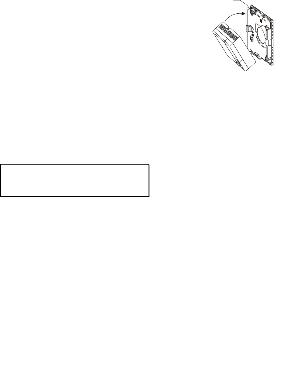
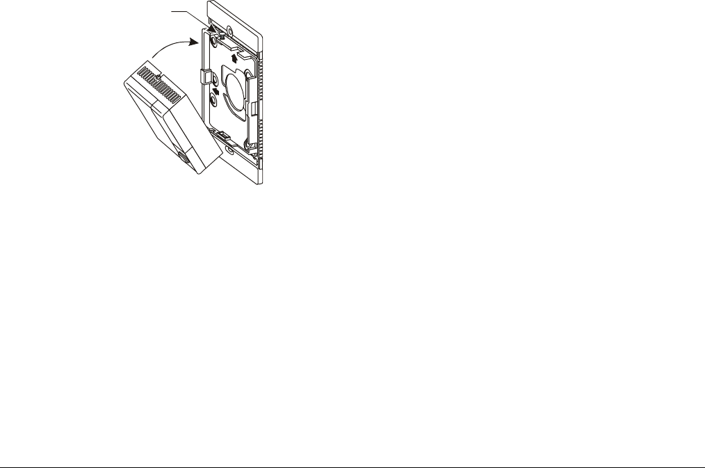
Removing the Transmitter from its Mounting Base
The WRS-TTx Series Transmitter ships from the
factory pre-assembled to its mounting base. In order to
secure the assembly to a surface, the transmitter must
first be removed from its mounting base (as illustrated
in Figure 2).
Diagram of Sensor Transmitter Cover and Base
Figure 2: Removing the Transmitter from its
Mounting Base
4 WRS-TTx Series Radio Frequency (RF) Wireless Transmitters Installation Instructions
Surface Mounting the Transmitter Using Two
Expandable Wall Anchors and Two No. 8
Pan-Head, Self-Tapping Screws
Two expandable wall anchors and two No. 8
pan-head, self-tapping screws are included with each
WRS-TTx Series Transmitter for surface mounting the
unit as follows:
1. Remove the transmitter from its mounting base (as
illustrated in Figure 2).
2. Select two mounting hole locations across from
one another on the mounting base. Mark these
two mounting hole locations on the wall surface
using the mounting base as a template.
Note: Before marking the two mounting hole
locations, be sure that the rectangular holes with
the little notches are towards the top. With the
notched rectangular holes at the top, the
transmitter is oriented properly once it is secured
to the mounting base.
3. Drill a 5/32 in. (4 mm) hole at each of the marked
locations.
4. Install an expandable wall anchor into each of the
drilled holes.
5. Secure the mounting base to the surface using the
two No. 8 pan-head, self-tapping screws provided.
IMPORTANT: Do not overtighten the mounting
screws. Overtightening the mounting screws may
damage the mounting base and the mounting
surface.
6. View the Property Code and Transmitter ID DIP
switch arrays on the back of the transmitter.
For a One-to-One application, set the Property
Code DIP switch array to all “Zeros.” Set the
address portion of the Transmitter ID DIP switch
array to match the corresponding TE-78XX
receiver DIP switch array.
For a Many-to-One application, set the Property
Code DIP switch array (1 to 31) and the address
portion of the Transmitter ID DIP switch array (1 to
511) to desired addresses for the designated
locations. (A “zero” setting is not allowed.) These
addresses will be downloaded via the NAE to a
WRS-RTN and be linked with specific Controllers.
See the Setup and Adjustments section for more
details.
7. Install the batteries into the battery compartment
located on the back of the transmitter, and set the
power DIP switch (top DIP switch on the
Transmitter ID DIP switch array) to the ON
position.
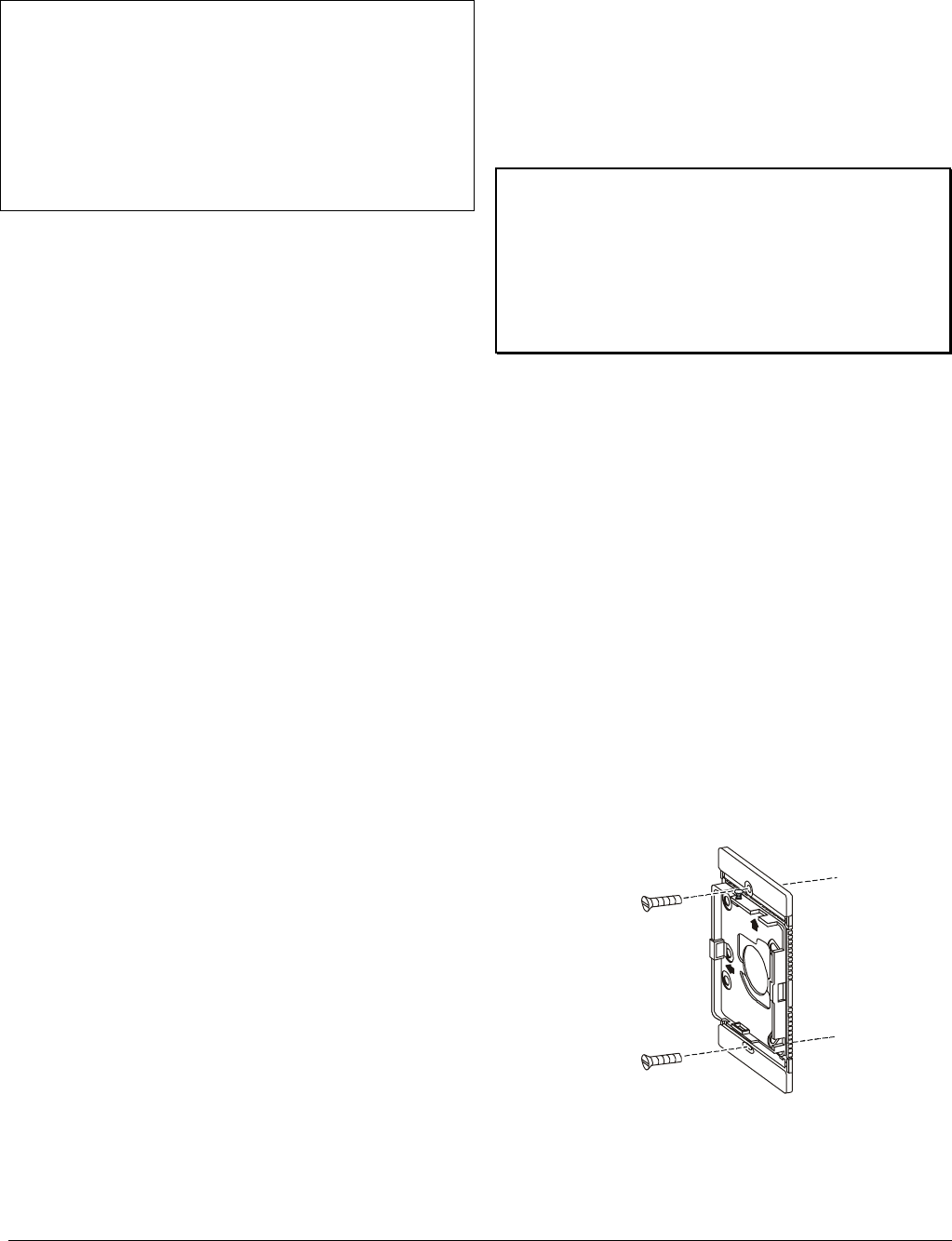
8. Place the bottom edge of the transmitter against
the bottom lip of the mounting base and rotate the
transmitter up onto the mounting base (as
illustrated in Figure 3).
Tamper-Proof
Transmitter Cover
Holding Screw
Note: This diagram needs to be replaced with
appropriate 80 X120 cover and base diagram
Figure 3: Securing the Transmitter to the
Mounting Base
9. Tighten the tamper-proof transmitter cover holding
screw using a 1/16 in. (2 mm) Allen-head
adjustment tool (T-4000-119; ordered separately)
to secure the transmitter to the mounting base.
Note: Once installed, the transmitter and
mounting base assembly cannot be removed from
the mounting surface without first loosening the
tamper-proof transmitter cover holding screw and
then depressing the tab at the top through the slot
using a small coin or a screwdriver. (as illustrated
in Figure 2).
Surface Mounting the Transmitter Using Three
Strips of Double-Sided Adhesive Foam Tape
Each WRS-TTx Series Transmitter includes three
1/16 in. (2 mm) thick, 3/4 x 1 in. (19 x 25 mm) strips of
double-sided adhesive foam tape for mounting
locations where building retention and its historical
preservation are important, or in buildings featuring
marble, granite, glass, mirrored, wood veneer, or other
decorative surfaces. To surface mount the transmitter
using the three strips of foam tape, proceed as follows:
1. Remove the transmitter from its mounting base (as
illustrated in Figure 2).
2. Clean the mounting surface to ensure that the
foam tape holds the mounting base securely to the
surface.
Note: The application temperature must be at
least 50°F (10°C).
3. Peel and stick one side of the foam tape strips to
the smooth surface of the mounting base,
arranged as illustrated in Figure 4.
WRS-TTx Series Radio Frequency (RF) Wireless Transmitters Installation Instructions 5
Diagram of back of sensor base plate showing foam
tape strips applied.
Figure 4: Locations of Foam Tape Strips on the
Smooth Surface of the Mounting Base
4. Peel the other side of the foam tape strips to
expose the sticky surface.
Note: Before placing the mounting base on the
surface, be sure that the rectangular holes with the
little notches are towards the top (as illustrated in
Figure 5). With the notched rectangular holes at
the top, the transmitter is oriented properly once it
is secured to the mounting base.
5. Place the mounting base on the desired surface
and press firmly to secure it in place.
6. View the Property Code and Transmitter ID DIP
switch arrays on the back of the transmitter.
For a One-to-One application, set the Property
Code DIP switch array to all “Zeros.” Set the
address portion of the Transmitter ID DIP switch
array to match the corresponding TE-78XX
receiver DIP switch array.
For a Many-to-One application, set the Property
Code DIP switch array (1 to 31) and the address
portion of the Transmitter ID DIP switch array (1 to
511) to desired addresses for the designated
locations. (A “zero” setting is not allowed.) These
addresses will be downloaded via the NAE to a
WRS-RTN and be linked with specific Controllers.
See the Setup and Adjustments section for more
details.
7. Install the batteries into the battery compartment
located on the back of the transmitter, and set the
power DIP switch (top DIP switch on the
Transmitter ID DIP switch array) to the ON
position.
8. Place the bottom edge of the transmitter against
the bottom lip of the mounting base and rotate the
transmitter up onto the mounting base (as
illustrated in Figure 6).
9. Tighten the tamper-proof transmitter cover holding
screw using a 1/16 in. (2 mm) Allen-head
adjustment tool (T-4000-119; ordered separately)
to secure the transmitter to the mounting base.
Note: Once installed, the transmitter and
mounting base assembly cannot be removed from
the mounting surface without first loosening the
tamper-proof transmitter cover holding screw and
then depressing the tab at the top through the slot
using a small coin or a screwdriver. (as illustrated
in Figure 2).
IMPORTANT: If the mounting base needs to
be removed and repositioned, the foam tape used to
secure it to the surface must be replaced with new
foam tape (purchased locally; Can-Do model
No. 99116 or equivalent). Remove the taped
mounting base from the surface by carefully twisting
it off, rather than pulling it off (to avoid damaging the
mounting surface).
Wallbox Mounting the Transmitter Using Two No. 8
Pan-Head, Self-Tapping Screws
The mounting base included with each WRS-
TTX Series Transmitter includes breakaway tabs that
must remain in place when mounting on a standard
2 x 4 in. (51 x 102 mm) wallbox. To wallbox mount the
transmitter using the two No. 8 pan-head, self-tapping
screws included with the unit, proceed as follows:
1. Remove the transmitter from its mounting base (as
illustrated in Figure 2).
2. Secure the mounting base to the wallbox using the
two No. 8 pan-head, self-tapping screws (as
illustrated in Figure 5).
Note: Before securing the mounting base to the
wallbox, be sure that the rectangular holes with
the little notches are towards the top (as illustrated
in Figure 5). With the notched rectangular holes at
the top, the transmitter is oriented properly once it
is secured to the mounting base.
Two No. 8
Pan-Head,
Self-Tapping
Screws
Note: This diagram needs to be replaced with
appropriate 80 X120 base diagram
Figure 5: Securing the Mounting Base to the
Wallbox
6 WRS-TTx Series Radio Frequency (RF) Wireless Transmitters Installation Instructions
3. View the Property Code and Transmitter ID DIP
switch arrays on the back of the transmitter.
For a One-to-One application, set the Property
Code DIP switch array to all “Zeros.” Set the
address portion of the Transmitter ID DIP switch
array to match the corresponding TE-78XX
receiver DIP switch array.
For a Many-to-One application, set the Property
Code DIP switch array (1 to 31) and the address
portion of the Transmitter ID DIP switch array (1 to
511) to desired addresses for the designated
locations. (A “zero” setting is not allowed.) These
addresses will be downloaded via the NAE to a
WRS-RTN and be linked with specific Controllers.
See the Setup and Adjustments section for more
details.
4. Install the battery into the battery compartment
located on the back of the transmitter, and set the
power DIP switch (top DIP switch on the
Transmitter ID DIP switch array) to the ON
position.
5. Place the bottom edge of the transmitter against
the bottom lip of the mounting base and rotate the
transmitter up onto the mounting base (as
illustrated in Figure 6).
Tamper-Proof
Transmitter Cover
Holding Screw
Note: This diagram needs to be replaced with
appropriate 80 X120 cover and base diagram
Figure 6: Securing the Transmitter to the
Mounting Base
6. Tighten the tamper-proof transmitter cover holding
screw using a 1/16 in. (2 mm) Allen-head
adjustment tool (T-4000-119; ordered separately)
to secure the transmitter to the mounting base.
Note: Once installed, the transmitter and
mounting base assembly cannot be removed from
the mounting surface without first loosening the
tamper-proof transmitter cover holding screw and
then depressing the tab at the top through the slot
using a small coin or a screwdriver. (as illustrated
in Figure 2).
Setup and Adjustments
For setup and commissioning details, refer to the
WRS-TTx Technical Bulletin (LIT-??????????)
Repairs and Replacement
If the WRS-TTx Series RF Wireless Temperature and
Set Point Transmitter, or the TE-7720 or
TE-7730 Series RF Receiver, or the WRS-RTN Series
RF Receiver fails to operate within its specifications,
unit replacement is required. For a replacement
transmitter or receiver, contact the nearest
Johnson Controls representative.
Table 2 includes the only replacement parts available
for the WRS Series RF Wireless Room Temperature
Sensing System. Do not attempt any repairs on the
temperature sensing system other than those related
to the replacement parts included in Table 2.
Note: The printed circuit board used with the
WRS Series RF Wireless Room Temperature Sensing
System is retained with a tamper-resistant mechanism.
Removing the printed circuit board from the plastic
housing voids the product warranty.
Replacing the Transmitter Battery
The life of the 1.5-volt AA Alkaline batteries included
with each WRS-TTx Series Transmitter is typically five
or more years. The transmitter communicates
diagnostic data, including battery condition,
approximately every 60 seconds to the receiver, where
it is converted into the appropriate units and electrical
format to warn supervisory equipment (via the
Johnson Controls digital controller) when the batteries
needs to be replaced.
For the WRS-RTN Series Receiver, a low battery
signal is sent to the NAE via the Ethernet trunk, and
this signal is not cleared until the transmitter battery is
replaced. For the TE-7820 Series Receiver, a low
battery signal is sent to the digital controller via the
zone bus link, and this signal is not cleared until the
transmitter battery is replaced.
For the TE-7830 Series Receiver, the low battery relay
binary output is turned off for 1 minute every 48 hours
and then back on again. This function is intended to
retrigger a system alarm that may have been
acknowledged without taking appropriate action to
replace the transmitter battery.
See Figure 2 to remove the transmitter from its
mounting base and access the battery for
replacement. Replacement batteries must be
purchased locally; suitable models include any good
quality Alkaline (1.5V) or Lithium (1.6V) AA cells. Do
not use Carbon/Zinc batteries as these will give a poor
life and could give erratic operation.

© 2005 Johnson Controls, Inc. 7
Part No. 24-xxxx-xx, Rev. - www.johnsoncontrols.com
Table 2: Replacement Parts (Order Separately)
Code Number Description
Duracell Ultra 123,
Panasonic CR123A,
Toshiba CR123A,
GE/Sanyo CR123A,
or Equivalent
Replacement Battery (Purchase Locally), 3.0-Volt Lithium Battery (One
Required for Receiver Signal Strength Site Survey Tool. These are NOT for the WRS-TTx
Sensor Transmitters which use Alkaline or Lithium AA cells)
Technical Specifications
Product
WRS Series RF Wireless Room Temperature Sensing System
TE-7820-0 Power and Zone Bus Interface Between TE-7820-0 RF Receiver and
VMA1400 Series Digital Controllers
TE-7830-0 Power and Analog Interface Between TE-7830-0 RF Receiver and
AS-AHU, AS-UNT, AS-VAV, DX-9100, and Compatible Competitors’
Digital Controllers
Digital Controller Interface
WRS-RTN0000-0
and NAE Ethernet interface between WRS-RTN and NAE. N2 or MSTP
interface between NAE and Digital Controllers
Transmitter Two AA cell Alkaline Batteries Included with Each Transmitter;
Battery Life: 60 Months Typical (48 Months Minimum);
Battery Condition Transmitted Approximately Every 60 Seconds
Power Requirements
Receiver 24 VAC +10%/-15%, 50/60 Hz, 4.5 VA, Class 2
WRS-TTx0000-0 DIP Switches, Field Adjustable for Up to 510 Unique Transmitter ID
Addresses and for up to 31 Unique Property Code Addresses.
TE-7820-0 DIP Switches, Field Adjustable for Up to 510 Unique Addresses
(For addresses 0 and 511, the TE-7720-0 matches the N2 address of
the associated VMA1400 for its actual address.)
TE-7830-0 DIP Switches, Field Adjustable for Up to 510 Unique Addresses
(Addresses 0 and 511 are invalid.)
Addressing
(Transmitter and Receiver)
WRS-RTN00000-0 Configurable via the NAE for Up to 512 Unique Transmitter ID
Addresses and Up to 31 Unique Property Code Addresses.
Measured
Temperature ±1F° (±0.6C°) Over a Range of 55 to 85°F (13 to 29°C);
±1.5F° (±0.9C°) Over a Range of 32 to 55°F (0 to 13°C) and
85 to 110°F (29 to 43°C)
System Accuracy
Temperature Set
Point ±1.5F° (±0.9C°) Over a Range of 55 to 85°F (13 to 29°C)
Transmitter Sensor Internal Negative Temperature Coefficient Thermistor
Continued on next page . . .

8 WRS-TTx Series Radio Frequency (RF) Wireless Transmitters Installation Instructions
Technical Specifications (Cont.)
Adjustment Single Temperature, Scaled °F/°C
Transmitter
Temperature Set Point Resolution Fahrenheit Scale Graduated in 5F° Intervals;
Celsius Scale Graduated in 2C° Intervals
Transmission Range
(Transmitter and Receiver) 500 ft (152.4 m) Maximum for Indoor Line-of-Sight;
200 ft (61 m) Practical Average Indoors
Transmissions Every 60 Seconds (±20 Seconds)
TE-7820-0 One Zone Bus Output for Temperature, Set Point, Field Strength
Measurements, and Low Battery Indication
TE-7830-0 Two Analog Outputs for Zone Temperature and Set Point:
0 to 5 VDC, 2 mA Maximum;
Two Binary Outputs for Occupancy and Low Battery Indication:
Dry Contacts Rated for 24 VAC, 50 mA Maximum
Receiver Outputs
WRS-
RTN0000-0 One Ethernet connection for communicating Temperature, Set Point,
Field Strength Measurements, and Low Battery Indication
Transmitter Two Expandable Wall Anchors (Preferred Mounting Method) or
Double-Sided Adhesive Foam Tape
Mounting Hardware
Receiver Four No. 6 Sheet Metal Screws
Transmitter 0 to 122°F (-18 to 50°C)
Ambient Operating
Temperature Limits Receiver 32 to 122°F (0 to 50°C)
Ambient Storage
Temperature Limits
(Transmitter and Receiver)
-40 to 160°F (-40 to 71°C)
Operating 5 to 95% RH, Noncondensing
Ambient Humidity Limits
(Transmitter and Receiver) Storage 5 to 90% RH, Noncondensing
Transmitter NEMA 1 White Plastic Housing
Materials
Receiver Gray Plastic Housing with UL94-5VB Flammability Rating
Intended for NEC Class 2 Connection
UL Listed, File E107041, CCN PAZX
UL94-5VB Flammability Rating (Receiver Housing is Plenum Rated per
UL 1995, Heating and Cooling Equipment)
FCC Compliant to CFR 47, Part 15, Subpart B, Class A
United States
Transmission Complies with FCC Part 15.247 Regulations for Low Power
Unlicensed Transmitters
Transmitter FCC Identification: CB2-TMPSENS2400A
Receiver Radio Module FCC Identification: CB2-RFMOD2400A
Intended for CEC Class 2 Connection
UL Listed, File E107041, CCN PAZX7
UL94-5VB Flammability Rating (Receiver Housing is Plenum Rated per
CSA C22.2 No. 236, Heating and Cooling Equipment)
Canada
Industry Canada (Transmitter) IC: 279A-TSENS24A
Industry Canada (Radio Module) IC: 279A-RFMOD24A
Compliance
Australia and
New Zealand Australia/NZ Emissions Compliant (C-Tick Mark)
Continued on next page . . .

WRS-TTx Series Radio Frequency (RF) Wireless Transmitters Installation Instructions 9
Technical Specifications (Cont.)
TE-7820-0 Two Spade Terminals that Accept One Two-Position, Screw-Terminal
Pluggable Block (Pluggable Block Included with Receiver)
TE-7830-0 Eight Spade Terminals that Accept One Two-Position and
Two Three-Position, Screw-Terminal Pluggable Blocks
(Pluggable Blocks Included with Receiver)
Receiver Terminations
WRS-
RTN0000-0 One Ethernet modular jack connector and a 3-Pin Header that Accepts
One Three-Position, Screw-Terminal Pluggable Block
(Pluggable Block Included with Receiver)
TE-7820-0 6 ft (1.8 m) Power and Zone Bus Interface Cable Included with
Each Receiver; Maximum Recommended Cable Length: 300 ft (91.4 m)
Cables to Connect Zone Bus Only (No Power) Measuring 25 ft (7.6 m),
50 ft (15.2 m), 75 ft (22.9 m), and 100 ft (30.5 m) are Available (Refer to
the TE-7800 Series Radio Frequency (RF) Wireless Room Temperature
Sensing System Product Bulletin [LIT-xxxxxxxx] for more details.)
Cable Between Receiver
and Johnson Controls
Digital Controller
TE-7830-0 6 ft (1.8 m) Power and Analog Interface Cable Included with
Each Receiver; Maximum Recommended Cable Length: 100 ft (30.5 m)
Transmitter 120 mm Long x 80 mm Wide x 38 mm High
Dimensions
Receiver 4-23/32 in. Long x 5-29/32 in. Wide x 1-31/32 in. High
(120 mm Long x 150 mm Wide x 50 mm High)
Transmitter 0.3 lb (0.14 kg)
Shipping Weights
Receiver 1.0 lb (0.45 kg)
The performance specifications are nominal and conform to acceptable industry standards. For application at conditions beyond these
specifications, consult the local Johnson Controls office. Johnson Controls, Inc. shall not be liable for damages resulting from misapplication or
misuse of its products.
Controls Group
507 E. Michigan Street
P.O. Box 423 Published in U.S.A.
Milwaukee, WI 53201 www.johnsoncontrols.com