Johnson Controls Inc Furnace Gg8S Mp Users Manual 356485 UIM F 0910
GGLS*MP to the manual 91ba63af-8c66-4e66-86ca-e4b43f2460bc
2015-02-09
: Johnson-Controls Johnson-Controls-Johnson-Controls-Inc-Furnace-Gg8S-Mp-Users-Manual-566967 johnson-controls-johnson-controls-inc-furnace-gg8s-mp-users-manual-566967 johnson-controls pdf
Open the PDF directly: View PDF ![]() .
.
Page Count: 30
356485-UIM-G-1211
RESIDENTIAL GAS FURNACE MODELS
TG8S*MP, TGLS*MP, GG8S*MP, GGLS*MP
(Single Stage Multi-position / Low NOx)
INSTALLATION MANUAL
LIST OF SECTIONS
SAFETY . . . . . . . . . . . . . . . . . . . . . . . . . . . . . . . . . . . . . . . . . . . . . . . 1
DUCTWORK . . . . . . . . . . . . . . . . . . . . . . . . . . . . . . . . . . . . . . . . . . . 5
FILTERS . . . . . . . . . . . . . . . . . . . . . . . . . . . . . . . . . . . . . . . . . . . . . . 9
GAS PIPING . . . . . . . . . . . . . . . . . . . . . . . . . . . . . . . . . . . . . . . . . . 10
ELECTRICAL POWER . . . . . . . . . . . . . . . . . . . . . . . . . . . . . . . . . . 12
TWINNING AND STAGING . . . . . . . . . . . . . . . . . . . . . . . . . . . . . . . 15
VENT SYSTEM . . . . . . . . . . . . . . . . . . . . . . . . . . . . . . . . . . . . . . . .16
START-UP AND ADJUSTMENTS . . . . . . . . . . . . . . . . . . . . . . . . . .19
SAFETY CONTROLS . . . . . . . . . . . . . . . . . . . . . . . . . . . . . . . . . . .26
REPLACEMENT PARTS LIST . . . . . . . . . . . . . . . . . . . . . . . . . . . .28
REPLACEMENT PART CONTACT INFORMATION . . . . . . . . . . . . 28
WIRING DIAGRAM . . . . . . . . . . . . . . . . . . . . . . . . . . . . . . . . . . . . .29
LIST OF FIGURES
Duct Attachment . . . . . . . . . . . . . . . . . . . . . . . . . . . . . . . . . . . . . . . . . 5
Vertical Applications . . . . . . . . . . . . . . . . . . . . . . . . . . . . . . . . . . . . . . 6
Coil Flange . . . . . . . . . . . . . . . . . . . . . . . . . . . . . . . . . . . . . . . . . . . . . 6
Horizontal Right Application . . . . . . . . . . . . . . . . . . . . . . . . . . . . . . . . 6
Horizontal Left Application . . . . . . . . . . . . . . . . . . . . . . . . . . . . . . . . . 6
PC Series Upflow Coil Installation . . . . . . . . . . . . . . . . . . . . . . . . . . . 7
Horizontal Left or Right application (Right Shown) . . . . . . . . . . . . . . 7
Combustible Floor Base Accessory . . . . . . . . . . . . . . . . . . . . . . . . . . 7
Horizontal Application . . . . . . . . . . . . . . . . . . . . . . . . . . . . . . . . . . . . 7
Typical Attic Installation . . . . . . . . . . . . . . . . . . . . . . . . . . . . . . . . . . . 8
Typical Suspended Furnace / Crawl Space Installation . . . . . . . . . . . 8
Dimensions . . . . . . . . . . . . . . . . . . . . . . . . . . . . . . . . . . . . . . . . . . . . 9
Side Return Cutout Markings . . . . . . . . . . . . . . . . . . . . . . . . . . . . . . 10
Gas Valve . . . . . . . . . . . . . . . . . . . . . . . . . . . . . . . . . . . . . . . . . . . . . 10
Gas Piping . . . . . . . . . . . . . . . . . . . . . . . . . . . . . . . . . . . . . . . . . . . . 10
Electrical Wiring . . . . . . . . . . . . . . . . . . . . . . . . . . . . . . . . . . . . . . . . 12
Thermostat Chart - Single Stage AC with
Single Stage PSC Furnaces . . . . . . . . . . . . . . . . . . . . . . . . . . . . . . . 13
Thermostat Chart - Single Stage HP with
Single Stage PSC Furnaces . . . . . . . . . . . . . . . . . . . . . . . . . . . . . . . 14
Typical Twinned Furnace Application . . . . . . . . . . . . . . . . . . . . . . . .15
Single Wire Twinning Wiring Diagram . . . . . . . . . . . . . . . . . . . . . . .16
Single Wire Staging Wiring Diagram . . . . . . . . . . . . . . . . . . . . . . . .16
Combustion Air Inducer . . . . . . . . . . . . . . . . . . . . . . . . . . . . . . . . . .16
Combustion Airflow Path Through The Furnace
Casing to the Burner Compartment . . . . . . . . . . . . . . . . . . . . . . . . .17
Outside and Ambient Combustion Air . . . . . . . . . . . . . . . . . . . . . . . .18
Gas Valve . . . . . . . . . . . . . . . . . . . . . . . . . . . . . . . . . . . . . . . . . . . . . 22
Reading Gas Pressure . . . . . . . . . . . . . . . . . . . . . . . . . . . . . . . . . . . 22
Furnace Control Board . . . . . . . . . . . . . . . . . . . . . . . . . . . . . . . . . . . 23
Wiring Diagram . . . . . . . . . . . . . . . . . . . . . . . . . . . . . . . . . . . . . . . . . 29
LIST OF TABLES
Unit Clearances to Combustibles . . . . . . . . . . . . . . . . . . . . . . . . . . . . 4
Coil Projection Dimensions - PC Series Coils . . . . . . . . . . . . . . . . . . 7
Cabinet and Duct Dimensions . . . . . . . . . . . . . . . . . . . . . . . . . . . . . . 9
Recommended Filter Sizes (High Velocity 600 FPM) . . . . . . . . . . . . 9
Nominal Manifold Pressure . . . . . . . . . . . . . . . . . . . . . . . . . . . . . . . 11
Ratings & Physical / Electrical Data . . . . . . . . . . . . . . . . . . . . . . . . . 12
Estimated Free Area . . . . . . . . . . . . . . . . . . . . . . . . . . . . . . . . . . . . 17
Unconfined Space Minimum Area . . . . . . . . . . . . . . . . . . . . . . . . . . 18
Free Area . . . . . . . . . . . . . . . . . . . . . . . . . . . . . . . . . . . . . . . . . . . . . 18
Gas Rate (CU FT/HR) . . . . . . . . . . . . . . . . . . . . . . . . . . . . . . . . . . .21
Inlet Gas Pressure Range . . . . . . . . . . . . . . . . . . . . . . . . . . . . . . . .22
Nominal Manifold Pressure . . . . . . . . . . . . . . . . . . . . . . . . . . . . . . . .22
Blower Performance CFM - Any Position
(without filter) - Bottom Return . . . . . . . . . . . . . . . . . . . . . . . . . . . . . 24
Blower Performance CFM - Any Position
(without filter) - Left Side Return . . . . . . . . . . . . . . . . . . . . . . . . . . . .25
These high efficiency, compact units employ induced combustion, reli-
able hot surface ignition and high heat transfer aluminized tubular heat
exchangers. The units are factory shipped for installation in upflow or
horizontal applications and may be converted for downflow applica-
tions.
These furnaces are designed for residential installation in a basement,
closet, alcove, attic, recreation room or garage and are also ideal for
commercial applications. All units are factory assembled, wired and
tested to assure safe dependable and economical installation and oper-
ation.
These units are Category I listed and may be common vented with
another gas appliance as allowed by the National Fuel Gas Code.
SECTION I: SAFETY
This is a safety alert symbol. When you see this symbol on
labels or in manuals, be alert to the potential for personal
injury.
Understand and pay particular attention to the signal words DANGER,
WARNING, or CAUTION.
DANGER indicates an imminently hazardous situation, which, if not
avoided, will result in death or serious injury.
WARNING indicates a potentially hazardous situation, which, if not
avoided, could result in death or serious injury.
CAUTION indicates a potentially hazardous situation, which, if not
avoided may result in minor or moderate injury. It is also used to
alert against unsafe practices and hazards involving only property dam-
age.
Improper installation may create a condition where the operation of
the product could cause personal injury or property damage.
Improper installation, adjustment, alteration, service or mainte-
nance can cause injury or property damage. Failure to carefully
read and follow all instructions in this manual can result in fur-
nace malfunction, death, personal injury and/or property dam-
age. Only a qualified contractor, installer or service agency should
install this product.
356485-UIM-G-1211
2Johnson Controls Unitary Products
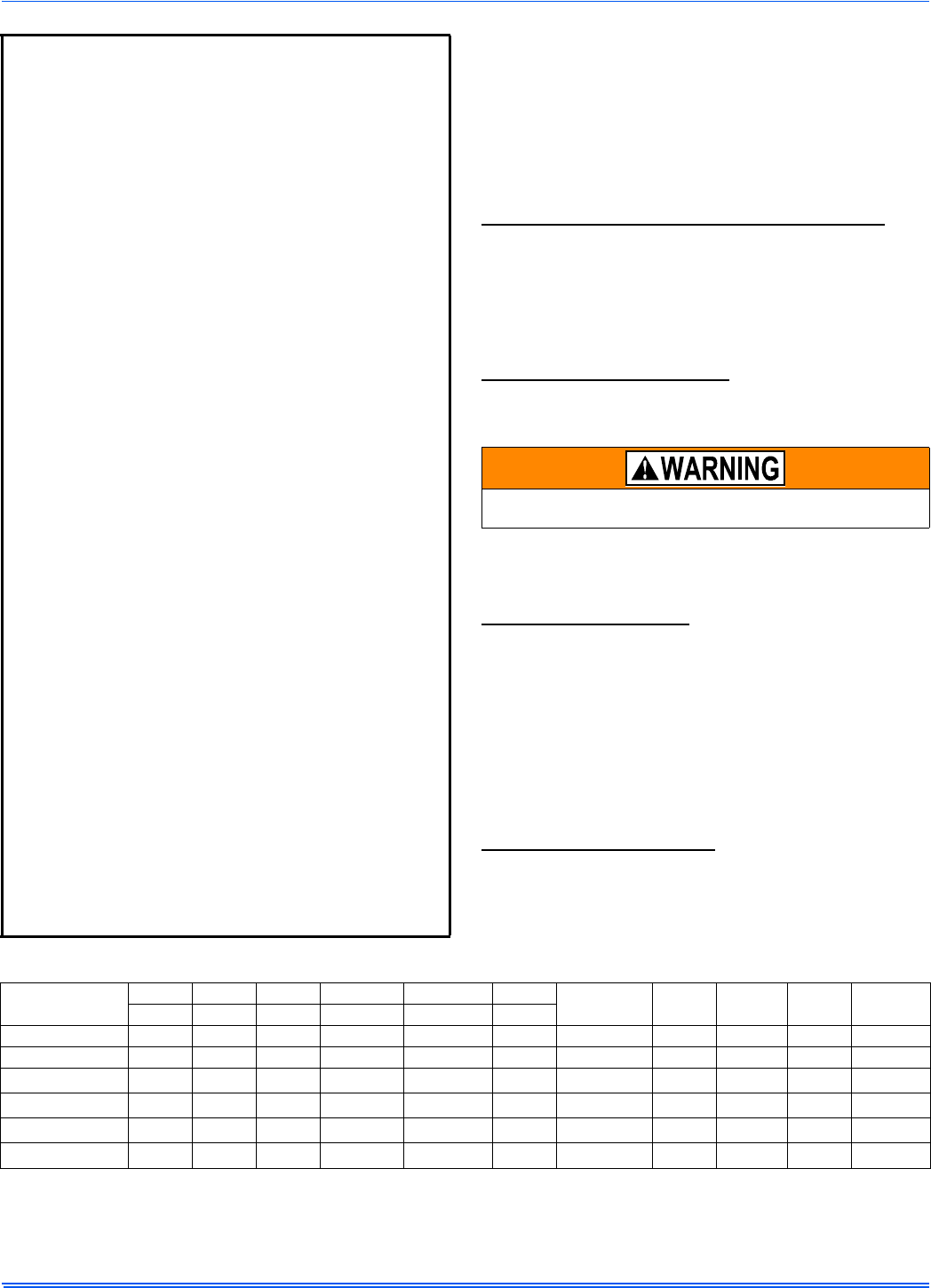
SPECIFIC SAFETY RULES AND PRECAUTIONS
1. Only Natural gas or Propane (LP) gas are approved for use with
this furnace.
2. Install this furnace only in a location and position as specified in
these instructions.
3. A gas-fired furnace for installation in a residential garage must be
installed as specified in these instructions.
4. Provide adequate combustion and ventilation air to the furnace
space as specified in these instructions.
5. Combustion products must be discharged outdoors. Connect this
furnace to an approved vent system only, as specified in SEC-
TION VII of these instructions.
6. Test for gas leaks as specified in these instructions.
7. Always install the furnace to operate within the furnace’s intended
temperature rise range. Only connect the furnace to a duct system
which has an external static pressure within the allowable range,
as specified on the furnace rating plate.
8. When a furnace is installed so that supply ducts carry air circulated
by the furnace to areas outside the space containing the furnace,
the return air shall also be handled by duct(s) sealed to the fur-
nace casing and terminating outside the space containing the fur-
nace.
9. It is permitted to use the furnace for heating of buildings or struc-
tures under construction where the application and use must com-
ply with all manufacturer’s installation instructions including:
• Proper vent installation;
• Furnace operating under thermostatic control;
• Return air duct sealed to the furnace;
• Air filters in place;
• Set furnace input rate and temperature rise per rating plate
marking;
• Means for providing outdoor air required for combustion;
• Return air temperature maintained between 55ºF (13ºC) and
80ºF (27ºC);
• The air filter must be replaced upon substantial completion of
the construction process;
• Clean furnace, duct work and components upon substantial
completion of the construction process, and verify furnace-
operating conditions including ignition, input rate, temperature
rise and venting, according to the manufacturer’s instructions.
10. When installed in a Non-HUD-Approved Modular Home or building
constructed on-site, combustion air shall not be supplied from
occupied spaces.
11. The size of the unit should be based on an acceptable heat loss
calculation for the structure. ACCA, Manual J or other approved
methods may be used.
12. When moving or handling this furnace prior to installation it is rec-
ommended to leave the doors on the furnace to provide support
and to prevent damage or warping of the cabinet. When lifting the
furnace by the cabinet, support the ends of the furnace rather than
lifting by the cabinet flanges at the return air openings (bottom or
sides) or supply air opening.
13. When lifting the furnace, it is acceptable to use the primary heat
exchanger tubes as a lifting point provided that the tubes are lifted
at the front of the heat exchangers where attached to the vestibule
panel. Do not use the top return bend of the heat exchangers as
lifting points as the tubes may shift out of position or their location
brackets/baffles.
SAFETY REQUIREMENTS
• Refer to the unit rating plate for the furnace model number, and
then see the dimensions page of this instruction for return air ple-
num dimensions in Figure 12. The plenum must be installed
according to the instructions.
• Provide clearances from combustible materials as listed under
Clearances to Combustibles.
• Provide clearances for servicing ensuring that service access is
allowed for both the burners and blower.
• These models ARE NOT CSA listed or approved for installation
into a HUD Approved Modular Home or a Manufactured
(Mobile) Home.
• This furnace is not approved for installation in trailers or recre-
ational vehicles.
• Furnaces for installation on combustible flooring shall not be
installed directly on carpeting, tile or other combustible material
other than wood flooring.
• Check the rating plate and power supply to be sure that the elec-
trical characteristics match. All models use nominal 115 VAC, 1
Phase, 60-Hertz power supply. DO NOT CONNECT THIS APPLI-
ANCE TO A 50 HZ POWER SUPPLY OR A VOLTAGE ABOVE
130 VOLTS.
• Furnace shall be installed so the electrical components are pro-
tected from water.
• Installing and servicing heating equipment can be hazardous due
to the electrical components and the gas fired components. Only
trained and qualified personnel should install, repair, or service
gas heating equipment. Untrained service personnel can perform
basic maintenance functions such as cleaning and replacing the
air filters. When working on heating equipment, observe precau-
tions in the manuals and on the labels attached to the unit and
other safety precautions that may apply.
FIRE OR EXPLOSION HAZARD
Failure to follow the safety warnings exactly could result in serious
injury, death or property damage.
Never test for gas leaks with an open flame. Use a commercially
available soap solution made specifically for detection of leaks to
check all connections. A fire or explosion may result causing prop-
erty damage, personal injury or loss of life.
During installation, doors should remain on the furnace when
moving or lifting.
This product must be installed in strict compliance with the installa-
tion instructions and any applicable local, state, and national codes
including, but not limited to building, electrical, and mechanical
codes.
356485-UIM-G-1211
Johnson Controls Unitary Products 3
COMBUSTION AIR QUALITY
(LIST OF CONTAMINANTS)
The furnace requires OUTDOOR AIR for combustion when the furnace
is located in any of the following environments.
• Restricted Environments
• Commercial buildings
• Buildings with indoor pools
• Furnaces installed in laundry rooms
• Furnaces installed in hobby or craft rooms
• Furnaces installed near chemical storage areas
• Chemical exposure
The furnace requires OUTDOOR AIR for combustion when the furnace
is located in an area where the furnace is being exposed to the follow-
ing substances and / or chemicals.
• Permanent wave solutions
• Chlorinated waxes and cleaners
• Chlorine based swimming pool chemicals
• Water softening chemicals
• De-icing salts or chemicals
• Carbon tetrachloride
• Halogen type refrigerants
• Cleaning solvents (such as perchloroethylene)
• Printing inks, paint removers, varnishes, etc.
• Hydrochloric acid
• Cements and glues
• Antistatic fabric softeners for clothes dryers
• Masonry acid washing materials
When outdoor air is used for combustion, the combustion air intake duct
system termination must be located external to the building and in an
area where there will be no exposure to the substances listed above.
CODES AND STANDARDS
Follow all national, local codes and standards in addition to this installa-
tion manual. The installation must comply with regulations of the serv-
ing gas supplier, local building, heating, plumbing, and other codes. In
absence of local codes, the installation must comply with the national
codes listed below and all authorities having jurisdiction.
In the United States and Canada, follow all codes and standards for the
following, using the latest edition available:
STEP 1 -Safety
• US: National Fuel Gas Code (NFGC) NFPA 54/ANSI Z223.1 and
the Installation Standards, Warm Air Heating and Air Conditioning
Systems ANSI/NFPA 90B
• CANADA: CAN/CGA-B149.1 National Standard of Canada. Natu-
ral Gas and Propane Installation Codes (NSCNGPIC)
STEP 2 -General Installation
• US: Current edition of the NFGC and NFPA 90B. For copies, con-
tact the
National Fire Protection Association Inc.
Batterymarch Park
Quincy, MA 02269
or for only the NFGC, contact the
American Gas Association,
400 N. Capital, N.W.
Washington DC 20001
or www.NFPA.org
• CANADA: NSCNGPIC. For a copy contact:
Standard Sales, CSA International
178 Rexdale Boulevard
Etobicoke, (Toronto) Ontario Canada M9W 1RS
STEP 3 -Combustion and Ventilation Air
• US: Section 5.3 of the NFGC, air for Combustion and Ventilation
• CANADA: Part 7 of NSCNGPIC, Venting Systems and Air Supply
for Appliances
STEP 4 -Duct Systems
• US and CANADA: Air Conditioning Contractors Association
(ACCA) Manual D, Sheet Metal and Air Conditioning Contractors
Association National Association (SMACNA), or American Soci-
ety of Heating, Refrigeration, and Air Conditioning Engineers
(ASHRAE) 1997 Fundamentals Handbook Chapter 32.
STEP 5 -Acoustical Lining and Fibrous Glass Duct
• US and CANADA: Current edition of SMACNA and NFPA 90B as
tested by UL Standard 181 for Class I Rigid Air Ducts
STEP 6 -Gas Piping and Gas Pipe Pressure Testing
• US: NFGC; chapters 2, 3, 4, & 9 and National Plumbing Codes
• CANADA: NSCNGPIC Part 5
STEP 7 -Electrical Connections
• US: National Electrical Code (NEC) ANSI/NFPA 70
• CANADA: Canadian Electrical Code CSA C22.1
These instructions cover minimum requirements and conform to exist-
ing national standards and safety codes. In some instances these
instructions exceed certain local codes and ordinances, especially
those who have not kept up with changing residential and non-HUD
modular home construction practices. These instructions are required
as a minimum for a safe installation.
The furnace area must not be used as a broom closet or for any
other storage purposes, as a fire hazard may be created. Never
store items such as the following on, near or in contact with the fur-
nace.
1. Spray or aerosol cans, rags, brooms, dust mops, vacuum
cleaners or other cleaning tools.
2. Soap powders, bleaches, waxes or other cleaning com-
pounds; plastic items or containers; gasoline, kerosene, ciga-
rette lighter fluid, dry cleaning fluids or other volatile fluid.
3. Paint thinners and other painting compounds.
4. Paper bags, boxes or other paper products
Never operate the furnace with the blower door removed. To
do so could result in serious personal injury and/or equipment
damage.
356485-UIM-G-1211
4Johnson Controls Unitary Products
INSPECTION
As soon as a unit is received, it should be inspected for possible dam-
age during transit. If damage is evident, the extent of the damage
should be noted on the carrier’s freight bill. A separate request for
inspection by the carrier’s agent should be made in writing. Also, before
installation, the unit should be checked for screws or bolts which may
have loosened in transit. There are no shipping or spacer brackets
which need to be removed from the interior of this unit.
FURNACE LOCATION AND CLEARANCES
The furnace shall be located using the following guidelines:
1. Where a minimum amount of air intake/vent piping and elbows will
be required.
2. As centralized with the air distribution as possible.
3. Where adequate combustion air will be available (particularly
when the appliance is not using outdoor combustion air).
4. Where it will not interfere with proper air circulation in the confined
space.
Installation in freezing temperatures:
1. Furnace shall be installed in an area where ventilation facilities
provide for safe limits of ambient temperature under normal oper-
ating conditions.
2. Do not allow return air temperature to be below 55º F (13° C) for
extended periods. To do so may cause condensation to occur in
the main heat exchanger, leading to premature heat exchanger
failure.
Clearances for access/service:
Ample clearances should be provided to permit easy access to the unit.
The following minimum clearances are recommended:
1. Twenty-four (24) inches (61 cm) between the front of the furnace
and an adjacent wall or another appliance, when access is
required for servicing and cleaning.
2. Eighteen (18) inches (46 cm) at the side where access is required
for passage to the front when servicing or for inspection or
replacement of flue/vent connections.
In all cases, accessibility clearances shall take precedence over clear-
ances for combustible materials where accessibility clearances are
greater.
Installation in a residential garage:
A gas-fired furnace for installation in a residential garage must be
installed so the burner(s) and the ignition source are located not less
than 18 inches (46 cm) above the floor, and the furnace must be located
or protected to avoid physical damage by vehicles.
FOR FURNACES INSTALLED IN THE COMMON-
WEALTH OF MASSACHUSETTS ONLY
For all side wall horizontally vented gas fueled equipment installed in
every dwelling, building or structure used in whole or in part for resi-
dential purposes, including those owned or operated by the Com-
monwealth and where the side wall exhaust vent termination is less
than seven (7) feet above finished grade in the area of the venting,
including but not limited to decks and porches, the following require-
ments shall be satisfied:
1. INSTALLATION OF CARBON MONOXIDE DETECTORS. At
the time of installation of the side wall horizontal vented gas
fueled equipment, the installing plumber or gasfitter shall
observe that a hard wired carbon monoxide detector with an
alarm and battery back-up is installed on the floor level where
the gas equipment is to be installed. In addition, the installing
plumber or gasfitter shall observe that a battery operated or
hard wired carbon monoxide detector with an alarm is installed
on each additional level of the dwelling, building or structure
served by the side wall horizontal vented gas fueled equipment.
It shall be the responsibility of the property owner to secure the
services of qualified licensed professionals for the installation of
hard wired carbon monoxide detectors
a. In the event that the side wall horizontally vented gas
fueled equipment is installed in a crawl space or an attic,
the hard wired carbon monoxide detector with alarm and
battery back-up may be installed on the next adjacent floor
level.
b. In the event that the requirements of this subdivision can
not be met at the time of completion of installation, the
owner shall have a period of thirty (30) days to comply with
the above requirements; provided, however, that during
said thirty (30) day period, a battery operated carbon mon-
oxide detector with an alarm shall be installed.
2. APPROVED CARBON MONOXIDE DETECTORS. Each car-
bon monoxide detector as required in accordance with the
above provisions shall comply with NFPA 720 and be ANSI/UL
2034 listed and IAS certified.
3. SIGNAGE. A metal or plastic identification plate shall be perma-
nently mounted to the exterior of the building at a minimum
height of eight (8) feet above grade directly in line with the
exhaust vent terminal for the horizontally vented gas fueled
heating appliance or equipment. The sign shall read, in print
size no less than one-half (1/2) inch in size, "GAS VENT
DIRECTLY BELOW. KEEP CLEAR OF ALL OBSTRUC-
TIONS".
4. INSPECTION. The state or local gas inspector of the side wall
horizontally vented gas fueled equipment shall not approve the
installation unless, upon inspection, the inspector observes car-
bon monoxide detectors and signage installed in accordance
with the provisions of 248 CMR 5.08(2)(a)1 through 4.
Improper installation in an ambient below 32ºF (0.0° C) could create
a hazard, resulting in damage, injury or death.
Table 1: Unit Clearances to Combustibles (All Dimensions in Inches, and All Surfaces Identified with the Unit in an Upflow Configuration)
Application Top Front Rear Left Side Right Side Flue Floor/
Bottom Closet Alcove Attic Line
Contact
In. (cm) In. (cm) In. (cm) In. (cm) In. (cm) In. (cm)
Upflow 1 (2.5) 1 (2.5) 0 (0.0) 0 (0.0) 0 (0.0) 6 (15.2) Combustible Yes Yes Yes No
Upflow B-Vent 1 (2.5) 1 (2.5) 0 (0.0) 0 (0.0) 0 (0.0) 1 (2.5) Combustible Yes Yes Yes No
Downflow 1 (2.5) 1 (2.5) 0 (0.0) 0 (0.0) 0 (0.0) 6 (15.2) 1 (25.4)1
1. Special floor base or air conditioning coil required for use on combustible floor.
Yes Yes Yes No
Downflow B-Vent 1 (2.5) 1 (2.5) 0 (0.0) 0 (0.0) 0 (0.0) 1 (2.5) 1 (25.4)1Yes Yes Yes No
Horizontal 1 (2.5) 1 (2.5) 0 (0.0) 0 (0.0) 0 (0.0) 6 (15.2) Combustible No Yes Yes Yes2
2. Line contact only permitted between lines formed by the intersection of the rear panel and side panel (top in horizontal position) of the furnace jacket and building
joists, studs or framing.
Horizontal B-Vent 1 (2.5) 1 (2.5) 0 (0.0) 0 (0.0) 0 (0.0) 1 (2.5) Combustible No Yes Yes Yes2
356485-UIM-G-1211
Johnson Controls Unitary Products 5
SECTION II: DUCTWORK
DUCTWORK GENERAL INFORMATION
The duct system’s design and installation must:
1. Handle an air volume appropriate for the served space and within
the operating parameters of the furnace specifications.
2. Be installed in accordance of National Fire Protection Association
as outlined in NFPA standard 90B (latest editions) or applicable
national, provincial, state, and local fire and safety codes.
3. Create a closed duct system. For residential and Non-HUD Modu-
lar Home installations, when a furnace is installed so that the sup-
ply ducts carry air circulated by the furnace to areas outside the
space containing the furnace, the return air shall also be handled
by a duct(s) sealed to the furnace casing and terminating outside
the space containing the furnace.
4. Complete a path for heated or cooled air to circulate through the
air conditioning and heating equipment and to and from the condi-
tioned space.
When the furnace is used with a cooling coil, the coil must be installed
parallel with, or in the supply air side of the furnace to avoid condensa-
tion in the primary heat exchanger. When a parallel flow arrangement is
used, dampers or other means used to control airflow must be ade-
quate to prevent chilled air from entering the furnace. If manually oper-
ated, the damper must be equipped with means to prevent the furnace
or the air conditioner from operating unless the damper is in full heat or
cool position.
When replacing an existing furnace, if the existing plenum is not the
same size as the new furnace then the existing plenum must be
removed and a new plenum installed that is the proper size for the new
furnace. If the plenum is shorter than 12” (30.5 cm) the turbulent air flow
may cause the limit controls not to operate as designed, or the limit con-
trols may not operate at all.
The duct system is a very important part of the installation. If the duct
system is improperly sized the furnace will not operate properly.
The ducts attached to the furnace plenum, should be of sufficient size
so that the furnace operates at the specified external static pressure
and within the air temperature rise specified on the nameplate.
If a matching cooling coil is used, it may be placed directly on the fur-
nace outlet and sealed to prevent leakage. If thermoplastic evaporator
‘A’ coil drain pans are to be installed in the upflow/horizontal configura-
tion, then extra 2” minimum spacing may be needed to ensure against
drain pan distortion.
On all installations without a coil, a removable access panel is recom-
mended in the outlet duct such that smoke or reflected light would be
observable inside the casing to indicate the presence of leaks in the
heat exchanger. This access cover shall be attached in such a manner
as to prevent leaks.
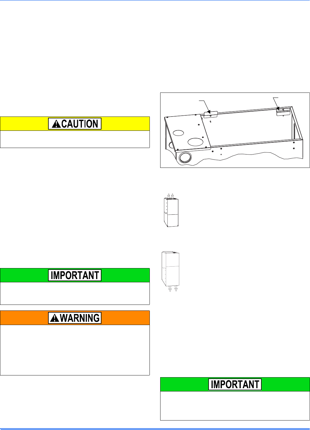
DUCT FLANGES
Four flanges are provided to attach ductwork to the furnace. These
flanges are rotated down for shipment. In order to use the flanges,
remove the screw holding an individual flange, rotate the flange so it is
in the upward position and reinstall the screw then repeat this for all 4
flanges.
If the flanges are not used, they must remain in the rotated down posi-
tion as shipped.
DUCTWORK INSTALLATION AND SUPPLY PLENUM
CONNECTION - UPFLOW/HORIZONTAL
Attach the supply plenum to the furnace outlet. The use of
an approved flexible duct connector is recommended on all
installations. This connection should be sealed to prevent
air leakage. The sheet metal should be crosshatched to
eliminate any popping of the sheet metal when the indoor
fan is energized.
FLOOR BASE AND DUCTWORK INSTALLATION -
DOWNFLOW
Installations on combustible material or directly on any
floors must use a combustible floor base shown in Figure 8.
Follow the instructions supplied with the combustible floor
base accessory. This combustible floor base can be
replaced with a matching cooling coil, properly sealed to
prevent leaks. Follow the instructions supplied with the
cooling coil cabinet for installing the cabinet to the duct con-
nector. Plug intake and vent pipe holes in bottom panel and
move grommet to desired vent side exit.
Downflow Air Conditioning Coil Cabinet
The furnace should be installed with coil cabinet part number specifi-
cally intended for downflow application. If a matching cooling coil is
used, it may be placed directly on the furnace outlet and sealed to pre-
vent leakage. For details of the coil cabinet dimensions and installation
requirements, refer to the installation instructions supplied with the coil
cabinet.
Attach the air conditioning coil cabinet to the duct connector, and then
position the furnace on top of the coil cabinet. The connection to the fur-
nace, air conditioning coil cabinet, duct connector, and supply air duct
must be sealed to prevent air leakage.
COIL INSTALLATION
The cooling coil must be installed in the supply air duct, down-
stream of the furnace. Cooled air may not be passed over the heat
exchanger.
The minimum plenum height is 12” (30.5 cm). The furnace will not
operate properly on a shorter plenum height. The minimum recom-
mended rectangular duct height is 4 inches (10 cm) attached to the
plenum.
The duct system must be properly sized to obtain the correct airflow
for the furnace size that is being installed.
Refer to Table 6 or the furnace rating plate for the correct rise range
and static pressures.
If the ducts are undersized, the result will be high duct static pres-
sures and/or high temperature rises which can result in a heat
exchanger OVERHEATING CONDITION. This condition can result
in premature heat exchanger failure, which can result in personal
injury, property damage, or death.
FIGURE 1: Duct Attachment
On all installations without a coil, a removable access panel is rec-
ommended in the outlet duct such that smoke or reflected light
would be observable inside the casing to indicate the presence of
leaks in the heat exchanger. This access cover shall be attached in
such a manner as to prevent leaks.
Factory
installed
For duct attachment,
if needed.
356485-UIM-G-1211
6Johnson Controls Unitary Products
COIL/FURNACE ASSEMBLY - MC/FC/PC SERIES
COILS
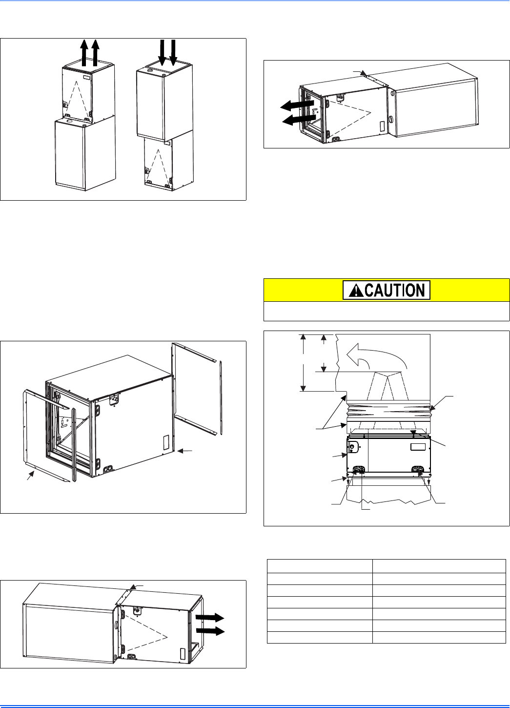
FURNACE ASSEMBLY - MC & FC SERIES COILS
These coils are factory shipped for installation in either upflow or down-
flow applications with no conversion.
Position the coil casing over or under the furnace opening as shown in
Figure 2 after configuring coil flanges as required see “Coil Flange” sec-
tion below.
COIL FLANGE INSTALLATION
The coils include removable flanges to allow proper fit up with furnaces
having various inlet and outlet flange configurations. The two flanges
are attached to the top of the coil in the factory during production. For
proper configuration of flanges refer to Figure 3.
FURNACE ASSEMBLY - MC SERIES COILS ONLY
MC coils are supplied ready to be installed in a horizontal position. A
horizontal pan is factory installed. MC coils should be installed in all hor-
izontal applications with the horizontal drain pan side down.
For horizontal left hand applications no conversion is required to an MC
coil when used with a downflow/horizontal furnace. A mounting plate,
supplied with every coil should always be installed on the side desig-
nated as top side. See Figures 4 & 5.
FURNACE ASSEMBLY - PC SERIES COILS
These upflow coils are designed for installation on top of upflow fur-
naces only.
If the coil is used with a furnace of a different size, use a 45° transition
to allow proper air distribution through the coil.
1. Position the coil casing over the furnace opening as shown in Fig-
ure 6.
2. Place the ductwork over the coil casing flange and secure.
3. Check for air leakage between the furnace and coil casing and
seal appropriately.
Dimension “C” should be at least 2/3 of dimension “D”. See Figure 6
FIGURE 2: Vertical Applications
FIGURE 3: Coil Flange
FIGURE 4: Horizontal Right Application
UPFLOW DOWNFLOW
Furnace
Furnace
ALTERNATE
FLANGE LOCATION
(Used for downflow or
horizontal left installations)
FACTORY
FLANGE
LOCATION
(Used for upflow
or horizontal
right installations)
Furnace
Mounting Plate
FIGURE 5: Horizontal Left Application
Do not drill any holes or drive any screws into the front duct flange
on the coil in order to prevent damaging coil tubing. See Figure 6
FIGURE 6: PC Series Upflow Coil Installation
Table 2: Coil Projection Dimensions - PC Series Coils
COIL SIZE DIMENSION “C” INCH
PC18 3-1/2
PC24 4-1/2
PC30, PC32, PC35 4-1/2
PC42, PC43, PC36, PC37 5-1/2
PC48 6-1/2
PC60 9
Furnace
Mounting Plate
Flexible
Duct Collar
Do not drill
or Screw
this flange
Field
Fabricated
Ductwork
Upflow
Coil
Upflow
Furnace
Secondary
Drain
Primary
Drain
D
C
(Min)
Alternate
Drain Location
356485-UIM-G-1211
Johnson Controls Unitary Products 7
CRITICAL COIL PROJECTION
The coil assembly must be located in the duct such that a minimum dis-
tance is maintained between the top of the coil and the top of the duct.
Refer to Table 2.
COIL / FURNACE ASSEMBLY - HC SERIES COILS
These coils are supplied ready to be installed in a right hand position or
a left hand position. When used in conjunction with a horizontal furnace
(blow through) application, the coil should be oriented with the opening
of the “A” coil closest to the furnace. See Figure 7.
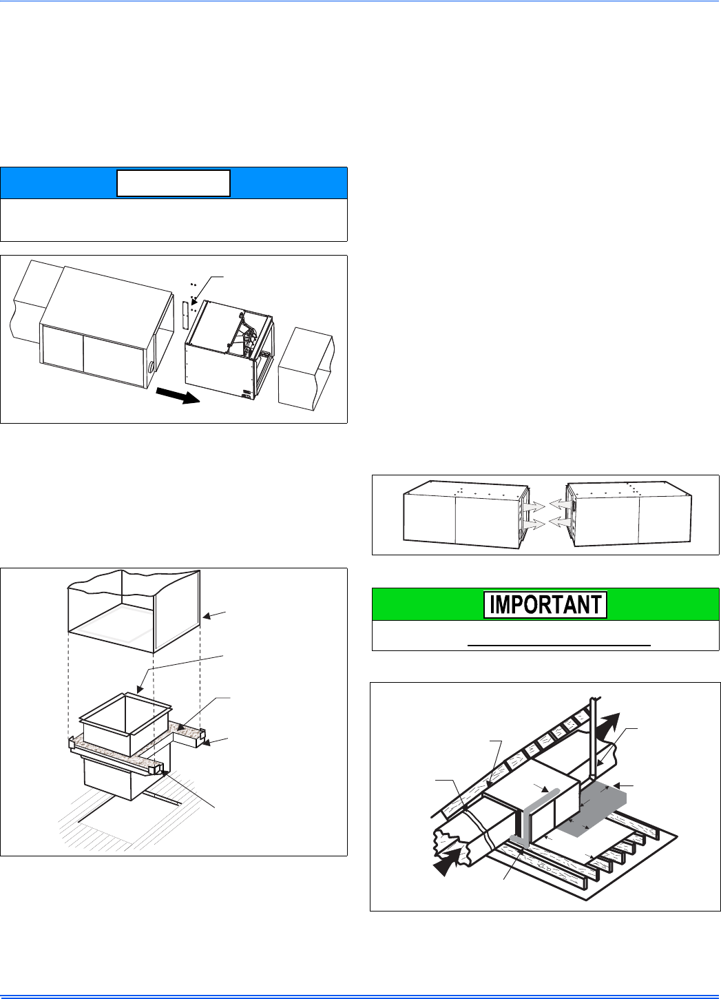
DOWNFLOW DUCT CONNECTORS
All downflow installations must use a suitable duct connector approved
by the furnace manufacturer for use with this furnace. The duct connec-
tors are designed to be connected to the rectangular duct under the
floor and sealed. Refer to the instructions supplied with the duct con-
nector for proper installation. Refer to the separate accessory parts list
at the end of these instructions for the approved accessory duct con-
nectors.
RESIDENTIAL AND MODULAR HOME UPFLOW
RETURN PLENUM CONNECTION
Return air may enter the furnace through the side(s) or bottom depend-
ing on the type of application. Return air may not be connected into the
rear panel of the unit.
SIDE RETURN APPLICATION
Side return applications pull return air through an opening cut in the
side of the furnace casing. This furnace is supplied with a bottom block-
off panel that should be left in place if a side return is to be used. If the
furnace is to be installed on a flat, solid surface, this bottom panel will
provide an adequate seal to prevent air leakage through the unused
bottom opening. However, if the furnace is to be installed on a surface
that is uneven, or if it is to be installed on blocks or otherwise raised off
the floor, it will be necessary to seal the edges of the bottom panel
to the casing using tape or other appropriate gasket material to
prevent air leakage.
BOTTOM RETURN AND ATTIC INSTALLATIONS
Bottom return applications normally pull return air through a base plat-
form or return air plenum. Be sure the return platform structure or return
air plenum is suitable to support the weight of the furnace.
The internal bottom panel must be removed for this application.
Attic installations must meet all minimum clearances to combustibles
and have floor support with required service accessibility.
DOWNFLOW APPLICATION
For downflow applications, the furnace must be turned upside-down so
that the circulating air enters at the top and exits the furnace at the bot-
tom. The combustion air inducer must be rotated 90° as shown in Fig-
ure 22. DO NOT BLOCK COMBUSTION AIR INLET OPENINGS.
HORIZONTAL APPLICATION
ATTIC INSTALLATION
Each coil is shipped with an external tie plate that should be used to
secure the coil to the furnace. It should be installed on the back side
of the coil using the dimpled pilot holes. See Figure 7.
FIGURE 7: Horizontal Left or Right application (Right Shown)
FIGURE 8: Combustible Floor Base Accessory
NOTICE
Use tie plate
supplied with coil
Air flow
Gas Furnace
FURNACE
WARM AIR PLENUM
WITH 1” FLANGES
FIBERGLASS
INSULATION
FIBERGLASS TAPE
UNDER FLANGE
COMBUSTIBLE FLOOR
BASE ACCESSORY
FIGURE 9: Horizontal Application
This furnace may be installed in a horizontal position on either side
as shown above. It must not be installed on its back.
FIGURE 10: Typical Attic Installation
Return
Air Sediment
Trap
Gas Piping
Supply
Air Vent (Maintain
required
clearances to
combustibles)
Line contact only permissible
between lines formed by the
intersection of furnace top
and two sides and building
joists, studs or framing
12”
30” MIN.
Work Area
Filter rack
must be a minimum
distance
of 18” (45.7 cm)
from the
furnace
12”
Sheet metal in
front of furnace
combustion air
Openings is
Recommended
356485-UIM-G-1211
8Johnson Controls Unitary Products
This appliance is certified for line contact when the furnace is installed
in the horizontal left or right position. The line contact is only permissible
between lines that are formed by the intersection of the top and two
sides of the furnace and the building joists, studs or framing. This line
may be in contact with combustible material. Refer to Figure 10.
When moving or handling this furnace prior to installation, always leave
the doors on the furnace to provide support and to prevent damage or
warping of the cabinet. When lifting the furnace, support the ends of the
furnace rather than lifting by the cabinet flanges at the return air open-
ings (bottom or sides) or supply air opening.
It is acceptable to use the primary heat exchanger tubes as a lifting
point provided that the tubes are lifted at the front of the heat exchang-
ers where attached to the vestibule panel. Do not use the top return
bend of the heat exchangers as lifting points as the tubes may shift out
of position or their location brackets/baffles.
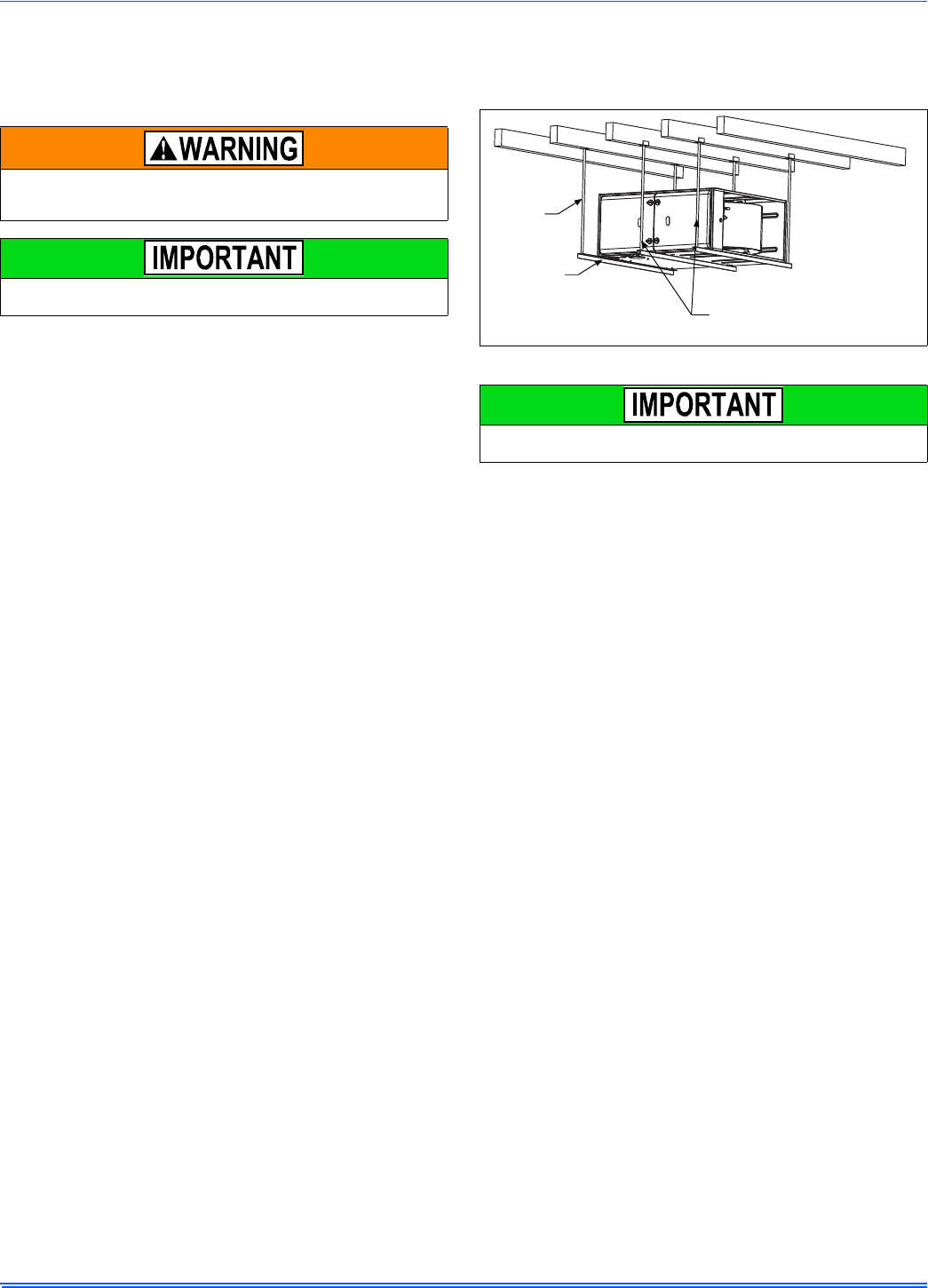
SUSPENDED FURNACE / CRAWL SPACE
INSTALLATION
The furnace can be hung from floor joists or installed on suitable blocks
or pads. Blocks or pad installations shall provide adequate height to
ensure that the unit will not be subject to water damage.
Units may also be suspended from rafters or floor joists using rods, pipe
angle supports or straps. In all cases, the furnace should be supported
with rods, straps, or angle supports at three locations to properly sup-
port the furnace. Place one support at the supply end of the furnace,
one support located approximately in the center of the furnace near the
blower shelf, and the third support should be at the return end of the fur-
nace. Maintain a 6” (15.2 cm) minimum clearance between the front of
the furnace and the support rods or straps.
All six suspension points must be level to ensure proper and quiet fur-
nace operation. When suspending the furnace, use a secure platform
constructed of plywood or other building materials secured to the floor
or ceiling joists. Refer to Figure 11 for details and additional information.
When moving or handling this furnace prior to installation it is recom-
mended to leave the doors on the furnace to provide support and to
prevent damage or warping of the cabinet. When lifting the furnace,
support the ends of the furnace rather than lifting by the cabinet flanges
at the return air openings (bottom or sides) or supply air opening.
It is acceptable to use the primary heat exchanger tubes as a lifting
point provided that the tubes are lifted at the front of the heat exchang-
ers where attached to the vestibule panel. Do not use the top return
bend of the heat exchangers as lifting points as the tubes may shift out
of position or their location brackets/baffles.
When a furnace is installed in an attic or other insulated space,
keep all insulating materials at least 12 inches (30.5 cm) away from
furnace and burner combustion air openings.
During installation, doors should remain on the furnace when
moving or lifting.
FIGURE 11: Typical Suspended Furnace / Crawl Space Installation
During installation, doors should remain on the furnace when
moving or lifting.
Support
Rod
Support
Angle (x3) Maintain 6” minimum
clearance between support
rods and front of furnace
356485-UIM-G-1211
Johnson Controls Unitary Products 9
SECTION III: FILTERS
FILTER INSTALLATION
All applications require the use of a field installed filter. All filters and
mounting provision must be field supplied.
Filters must be installed external to the furnace cabinet. DO NOT
attempt to install filters inside the furnace.
1. Air velocity through throwaway type filters may not exceed 300 feet per min-
ute (91.4 m/min). All velocities over this require the use of high velocity fil-
ters.
2. Do not exceed 1800 CFM using a single side return and a 16x25 filter. For
CFM greater than 1800, you may use two side returns or one side and the
bottom or one return with a transition to allow use of a 20x25 filter.
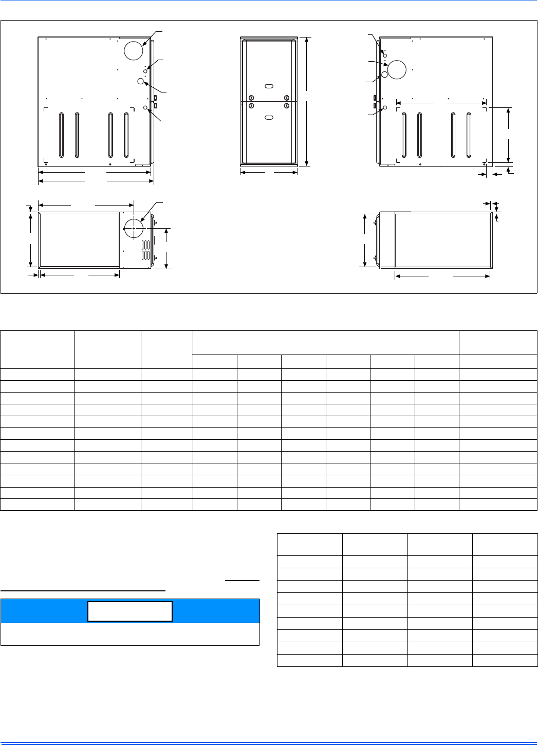
FIGURE 12: Dimensions
LEFT SIDE RIGHT SIDE
.5”
.5”
RETURN END
B
24.25”
29.5”
28.5”
Electrical
Entry
Gas Pipe
Entry
Thermostat
Wiring
FRONT
14”
1”
1.5”
23”
SUPPLY END
C
24.38”
20”
.5”
B
Gas Pipe
Entry
Thermostat
Wiring
33”
A
.5”
Electrical
Entry
Vent Connection
Outlet
Vent
Connection
Outlet
4” Diameter
Outlet
Vent Connection
Table 3: Cabinet and Duct Dimensions
BTUH (kW)
Input
Nominal
CFM (m3/min)
Cabinet
Size
Cabinet Dimensions (Inches) Approximate
Operating Weights
AA (cm)BB (cm)CC (cm) Lbs
40 (11.7) 800 (22.7) A 14 1/2 36.8 13 3/8 34.0 10.3 26.2 89
60 (17.6) 1000 (28.3) A 14 1/2 36.8 13 3/8 34.0 10.3 26.2 91
60 (17.6) 1200 (34.0) A 14 1/2 36.8 13 3/8 34.0 10.3 26.2 94
80 (23.4) 1200 (34.0) B 17 1/2 44.4 16 3/8 41.6 11.8 29.9 103
80 (23.4) 1600 (45.3) C 21 53.3 19 7/8 50.5 13.6 34.5 114
80 (23.4) 2200 (62.3) C 21 53.3 19 7/8 50.5 13.6 34.5 119
100 (29.3) 1200 (34.0) B 17 1/2 44.4 16 3/8 41.6 11.8 29.9 108
100 (29.3) 1600 (45.3) C 21 53.3 19 7/8 50.5 13.6 34.5 118
100 (29.3) 2000 (56.6) C 21 53.3 19 7/8 50.5 13.6 34.5 122
120 (35.1) 1600 (45.3) C 21 53.3 19 7/8 50.5 15.8 40.1 123
120 (35.1) 2000 (56.6) C 21 53.3 19 7/8 50.5 15.8 40.1 129
130 (38.1) 2000 (56.6) D 24 1/2 62.2 23 3/8 59.4 17.5 44.4 135
Single side return above 1800 CFM is approved as long as the filter
velocity does not exceed filter manufacturer’s recommendation.
NOTICE
Table 4: Recommended Filter Sizes (High Velocity 600 FPM)
CFM
(m³/min) Cabinet
Size Side
(in) Bottom
(in)
800 (22.7) A 16 x 25 14 x 25
1000 (28.3) A 16 x 25 14 x 25
1200 (34.0) A 16 x 25 14 x 25
1200 (34.0) B 16 x 25 16 x 25
1600 (45.3) B 16 x 25 16 x 25
1600 (45.3) C 16 x 25 20 x 25
2000 (56.6) C (2) 16 x 25 20 x 25
2200 (62.3) C (2) 16 x 25 20 x 25
2000 (56.6) D (2) 16 x 25 22 x 25
356485-UIM-G-1211
10 Johnson Controls Unitary Products
SIDE RETURN
Locate the “L” shaped corner locators. These indicate the size of the cut-
out to be made in the furnace side panel. Refer to Figure 13.
Install the side filter rack following the instructions provided with that
accessory. If a filter(s) is provided at another location in the return air
system, the ductwork may be directly attached to the furnace side
panel.
HORIZONTAL APPLICATION
Horizontal Filters
Any branch duct (rectangular or round duct) attached to the plenum
must attach to the vertical plenum before the filter. The use of straps
and / or supports is required to support the weight of the external filter
box.
Downflow Filters
Downflow furnaces typically are installed with the filters located above
the furnace, extending into the return air plenum or duct. Any branch
duct (rectangular or round duct) attached to the plenum must attach to
the vertical plenum above the filter height.
Filter(s) may be located in the duct system external to the furnace using
an external duct filter box attached to the furnace plenum or at the end
of the duct in a return filter grille(s). The use of straps and/or supports is
required to support the weight of the external filter box.
SECTION IV: GAS PIPING
GAS SAFETY
GAS PIPING INSTALLATION
Properly sized wrought iron, approved flexible or steel pipe must be
used when making gas connections to the unit. If local codes allow the
use of a flexible gas appliance connection, always use a new listed con-
nector. Do not use a connector that has previously serviced another gas
appliance.
Some utility companies or local codes require pipe sizes larger than the
minimum sizes listed in these instructions and in the codes. The furnace
rating plate and the instructions in this section specify the type of gas
approved for this furnace - only use those approved gases. The instal-
lation of a drip leg and ground union is required. Refer to Figure 15.
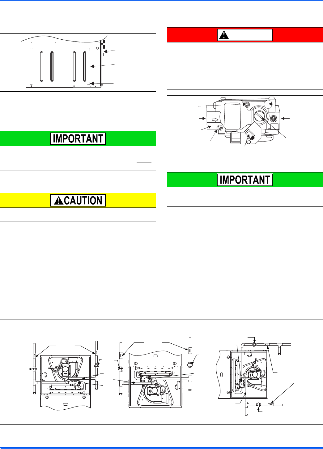
FIGURE 13: Side Return Cutout Markings
Some accessories such as electronic air cleaners and pleated
media may require a larger side opening. Follow the instructions
supplied with that accessory for side opening requirements. Do not
cut the opening larger than the dimensions shown in Figure 12.
All filters and mounting provision must be field supplied. All installa-
tions must have a filter installed.
Front of
Furnace
Corner
Markings
Side of
Furnace
An overpressure protection device, such as a pressure regulator,
must be installed in the gas piping system upstream of the furnace
and must act to limit the downstream pressure to the gas valve so it
does not exceed 0.5 PSI (14" w.c. (3.48 kPa). Pressures exceeding
0.5 PSI (14” w.c. (3.48 kPa) at the gas valve will cause damage to
the gas valve, resulting in a fire or explosion or cause damage to
the furnace or some of its components that will result in property
damage and loss of life.
FIGURE 14: Gas Valve
Plan your gas supply before determining the correct gas pipe entry.
Use 90-degree service elbow(s), or short nipples and conventional
90-degree elbow(s) to enter through the cabinet access holes.
DANGER
Inlet
Wrench
Boss
Inlet
Pressure
Port
ON
OFF
On/Off Switch
(Shown in ON position)
Main Regulator
Adjustment
Outlet
Outlet
Pressure
Port
Vent Port
FIGURE 15: Gas Piping
Upflow
Configuration
Downflow
Configuration
Horizontal
Configuration
External
Manual
Shut-off
Valve
External
Manual
Shut-off
Valve
External
Manual
Shut-off
Valve
To Gas
Supply
To Gas
Supply To Gas
Supply
To Gas
Supply
To Gas
Supply
To Gas
Supply
Drip
Leg
Drip
Leg Drip
Leg
Drip
Leg
Drip Leg
Drip Leg
Gas
Valve
Gas
Pipe
Gas
Valve
Gas Pipe
Gas
Valve
Ground
Union
Ground
Union
Ground
Union
Ground
Union
Ground
Union
NOTE: Ground Union maybe installed inside or outside unit.
356485-UIM-G-1211
Johnson Controls Unitary Products 11
The furnace must be isolated from the gas supply piping system by
closing its individual external manual shutoff valve during any pressure
testing of the gas supply piping system at pressures equal to or less
than 1/2 psig (3.5 kPa).
Gas piping may be connected from either side of the furnace using any
of the gas pipe entry on both sides of the furnace. Refer to Figure 12.
GAS ORIFICE CONVERSION FOR PROPANE (LP)
This furnace is constructed at the factory for natural gas-fired operation,
but may be converted to operate on propane (LP) gas by using a fac-
tory-supplied LP conversion kit. Follow the instructions supplied with
the LP kit.
HIGH ALTITUDE GAS ORIFICE CONVERSION
This furnace is constructed at the factory for natural gas-fired operation
at 0 –5,000 feet (0-m – 1,524 m) above sea level.
The manifold pressure must be changed in order to maintain proper
and safe operation when the furnace is installed in a location where the
altitude is greater than 5,000 feet (1,524 m) above sea level. Refer to
Table 5 for proper manifold pressure settings.
HIGH ALTITUDE PRESSURE SWITCH CONVERSION
For installation where the altitude is less than 5,000 feet (1,524m), it is
not required that the pressure switch be changed unless you are in an
area subject to low pressure inversions.
An accessible manual shutoff valve must be installed upstream of
the furnace gas controls and within 6 feet (1.8 m) of the furnace.
The gas valve body is a very thin casting that cannot take any
external pressure. Never apply a pipe wrench to the body of the gas
valve when installing piping. A wrench must be placed on the octa-
gon hub located on the gas inlet side of the valve. Placing a wrench
to the body of the gas valve will damage the valve causing improper
operation and/or the valve to leak.
LoNOx furnaces requiring propane (LP) gas must have the LoNOx
screens removed prior to installation and operation. See propane
instructions.
Table 5: Nominal Manifold Pressure
Manifold Pressures (in wc) Manifold Pressures (kpa)
Altitude (feet) Altitude (m)
0-7999 8000-8999 9000-9999 0-2437 2438-2742 2743-3048
Gas Heating Value
(BTU/cu ft.)
800 3.5 3.5 3.5
Gas Heating Value
(MJ/cu m)
29.80.870.870.87
850 3.5 3.5 3.5 31.70.870.870.87
900 3.5 3.5 3.5 33.50.870.870.87
950 3.5 3.5 3.3 35.40.870.870.81
1000 3.5 3.2 2.9 37.3 0.87 0.80 0.73
1050 3.5 2.9 2.7 39.1 0.87 0.73 0.67
1100 3.2 2.7 2.4 41.00.800.660.61
2500 (LP) 9.8 8.2 7.5 93.2 (LP) 2.44 2.03 1.86
PROPANE AND HIGH ALTITUDE CONVERSION KITS
It is very important to choose the correct kit and/or gas orifices for the altitude and the type of gas for which the furnace is being installed.
Only use natural gas in furnaces designed for natural gas. Only use propane (LP) gas for furnaces that have been properly converted to use pro-
pane (LP) gas. Do not use this furnace with butane gas.
Incorrect gas orifices or a furnace that has been improperly converted will create an extremely dangerous condition resulting in premature heat
exchanger failure, excessive sooting, high levels of carbon monoxide, personal injury, property damage, a fire hazard and/or death.
High altitude and propane (LP) conversions are required in order for the appliance to satisfactory meet the application.
An authorized distributor or dealer must make all gas conversions.
In Canada, a certified conversion station or other qualified agency, using factory specified and/or approved parts, must perform the conversion.
The installer must take every precaution to insure that the furnace has been converted to the proper gas orifice size when the furnace is installed.
Do not attempt to drill out any orifices to obtain the proper orifice size. Drilling out a gas orifice will cause misalignment of the burner flames,
causing premature heat exchanger burnout, high levels of carbon monoxide, excessive sooting, a fire hazard, personal injury, property damage
and/or death.
DANGER
356485-UIM-G-1211
12 Johnson Controls Unitary Products
SECTION V: ELECTRICAL POWER
ELECTRICAL POWER CONNECTIONS
Field wiring to the unit must be grounded. Electric wires that are field
installed shall conform to the temperature limitation for 63°F (35°C) rise
wire when installed in accordance with instructions. Refer to Table 6 in
these instructions for specific furnace electrical data.
Annual Fuel Utilization Efficiency (AFUE) numbers are determined in accordance with DOE Test procedures.
Wire size and over current protection must comply with the National Electrical Code (NFPA-70-latest edition) and all local codes.
The furnace shall be installed so that the electrical components are protected from water.
SUPPLY VOLTAGE CONNECTIONS
1. Provide a power supply separate from all other circuits. Install
overcurrent protection and disconnect switch per local/national
electrical codes. The switch should be close to the unit for conve-
nience in servicing. With the disconnect or fused switch in the OFF
position, check all wiring against the unit wiring label. Refer to the
wiring diagram in this instruction.
2. Remove the screws retaining the wiring box cover. Route the
power wiring through the opening in the unit into the junction box
with a conduit connector or other proper connection. In the junc-
tion box there will be 3 wires, a Black Wire, a White Wire. Connect
the power supply as shown on the unit-wiring label on the inside of
the blower compartment door or the wiring schematic in this sec-
tion. The black furnace lead must be connected to the L1 (hot)
wire from the power supply. The white furnace screw must be con-
nected to neutral. Connect the power supply ground to the green
screw (equipment ground) An alternate wiring method is to use a
field provided 2” (5.1 cm) x 4” (10.2 cm) box and cover on the out-
side of the furnace. Route the furnace leads into the box using a
protective bushing where the wires pass through the furnace
panel. After making the wiring connections replace the wiring box
cover and screws. Refer to Figure 16.
3. The furnace's control system requires correct polarity of the power
supply and a proper ground connection. Refer to Figure 16
LOW VOLTAGE CONTROL WIRING CONNECTIONS
Install the field-supplied thermostat by following the instructions that
come with the thermostat. With the thermostat set in the OFF position
and the main electrical source disconnected, connect the thermostat
wiring from the wiring connections on the thermostat to the terminal
board on the ignition module, as shown in Figures 17 or 18. Electronic
thermostats may require the common wire to be connected. Apply
strain relief to thermostat wires passing through cabinet. If air condition-
ing equipment is installed, use thermostat wiring to connect the Y and C
terminals on the furnace control board to the proper wires on the con-
densing unit (unit outside).
The 24-volt, 40 VA transformer is sized for the furnace components
only, and should not be connected to power auxiliary devices such as
humidifiers, air cleaners, etc. The transformer may provide power for an
air conditioning unit contactor.
Use copper conductors only.
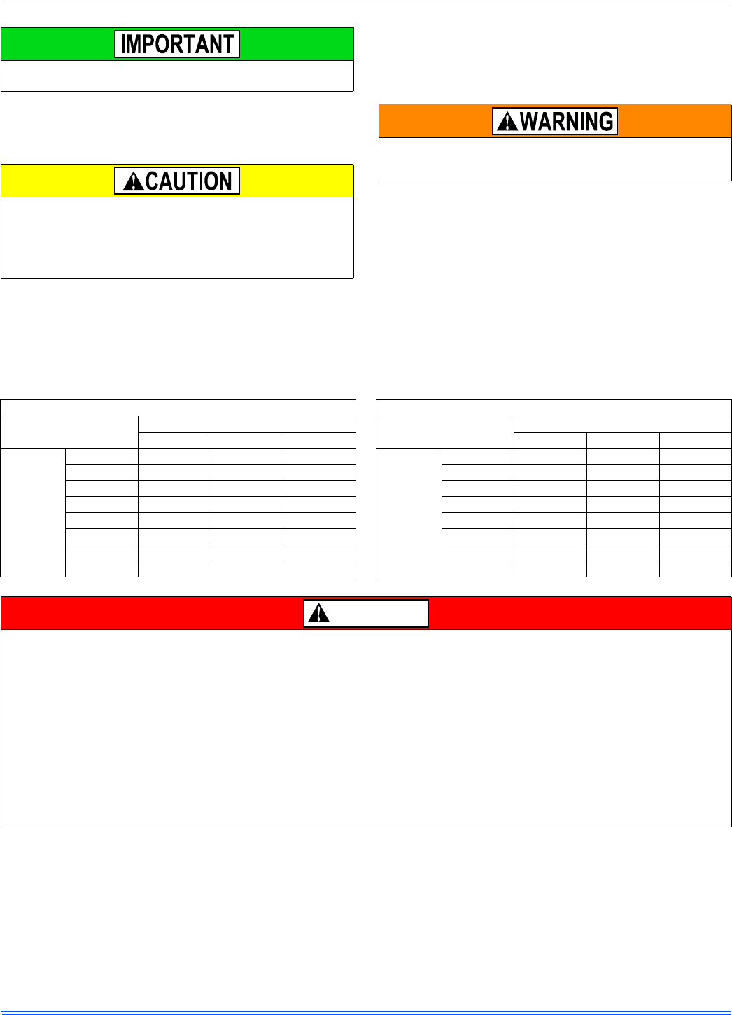
Table 6: Ratings & Physical / Electrical Data
Input Output Nominal
Airflow AFU
E
Air Temp.
Rise
Max.
Outlet
Air Temp Blower Blower
Size
Max
Over-Current
Protect
Total
Unit
Amps
Min. wire Size
(awg) @ 75 ft
one way
MB
HkW MB
HkW CFM m3/
min °F °C °F °C HP Amp
s
40 11.7 32 9.4 800 22.7 80.0 25-55 14-31 155 68.3 1/5 2.1 9 x 8 10 4.5 14
60 17.6 48 14.1 1000 28.3 80.0 25-55 14-31 155 68.3 1/3 3.8 9 x 8 10 6.0 14
60 17.6 48 14.1 1200 34.0 80.0 30-60 17-33 170 76.7 1/3 4.8 11 x 8 10 7.0 14
80 23.5 64 18.8 1200 34.0 80.0 35-65 19-36 165 73.9 1/3 4.8 11 x 8 10 7.5 14
80 23.5 64 18.8 1600 45.3 80.0 25-55 14-31 155 68.3 1/2 7.5 11 x 10 15 10.0 14
80 23.5 64 18.8 2200 62.3 80.0 25-55 14-31 155 68.3 1 14.5 11 x 11 20 16.0 12
100 29.3 80 23.4 1200 34.0 80.0 40-70 22-39 170 76.7 1/3 4.8 9 x 8 10 7.5 14
100 29.3 80 23.4 1600 45.3 80.0 35-65 19-36 165 73.9 1/2 7.5 11 x 10 15 10.0 14
100 29.3 80 23.4 2000 56.6 80.0 25-55 14-31 155 68.3 1 14.5 11 x 11 20 17.0 12
120 33.7 96 26.9 1600 45.3 80.0 40-70 22-39 170 76.7 1/2 7.5 11 x 10 15 10.0 14
120 33.7 96 26.9 2000 56.6 80.0 30-60 17-33 160 71.1 1 14.5 11 x 11 20 17.0 12
130 38.1 104 30.5 2000 56.6 80.0 35-65 19-36 165 73.9 1 14.5 11 x 11 20 17.0 12
FIGURE 16: Electrical Wiring
Electrical Entry
Junction
Box
L1-Hot
Neutral
Connect ground
lead to screw
BLK
WHT
The power connection leads and wiring box may be relocated to the
left side of the furnace. Remove the screws and cut wire tie holding
excess wiring. Reposition on the left side of the furnace and fasten
using holes provided.
Set the heat anticipator in the room thermostat to 0.4 amps. Setting
it lower will cause short cycles. Setting it higher will cause the room
temperature to exceed the set points.
Some electronic thermostats do not have adjustable heat anticipa-
tors. They should be set to six cycles per hour. Follow the thermo-
stat manufacturer's instructions.
356485-UIM-G-1211
Johnson Controls Unitary Products 13
For additional connection diagrams for all UPG equipment refer to “Low Voltage System Wiring” document available online at www.upgnet.com in the
Product Catalog Section.
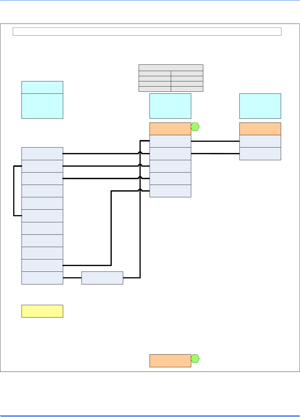
FIGURE 17: Thermostat Chart - Single Stage AC with Single Stage PSC Furnaces
AC 5D Single Stage Air Conditioner – Single Stage PSC Furnace
HM1
Humidistat
Y
Full Stage Compressor
G
Fan
*PP11C70224
THERMOSTAT
RH
24 – Volt Hot
(Heat XFMR)
RC
24 – Volt Hot
(Cool XFMR)
W
Full Stage Heat
Clipping Jumper W914 for
electric heat on thermostat
is not necessary
24VAC Humidifier
(Optional)
C
24 – Volt Common
Y
Compressor
SINGLE STAGE
AIR CONDITIONER
Y
Compressor Contactor
SINGLE STAGE
AIR
CONDITIONER
SINGLE STAGE
AIR CONDITIONER
G8C
L(Y/M)8S
G*9F
G*(8/9)S
ID MODELS
(G/T)GLS
(G,T)G(8/9)S
LF8
GF(8/9)
C
24 – Volt Common
R
24 – Volt Hot
W
Full Stage Heat
SINGLE STAGE PSC
FURNACE
G
Fan
SINGLE STAGE
PSC
FURNACE
Other Part Numbers:
SAP = Legacy
265901 = 031-09166
1
1
Y/Y2
Full Stage Compressor
356485-UIM-G-1211
14 Johnson Controls Unitary Products
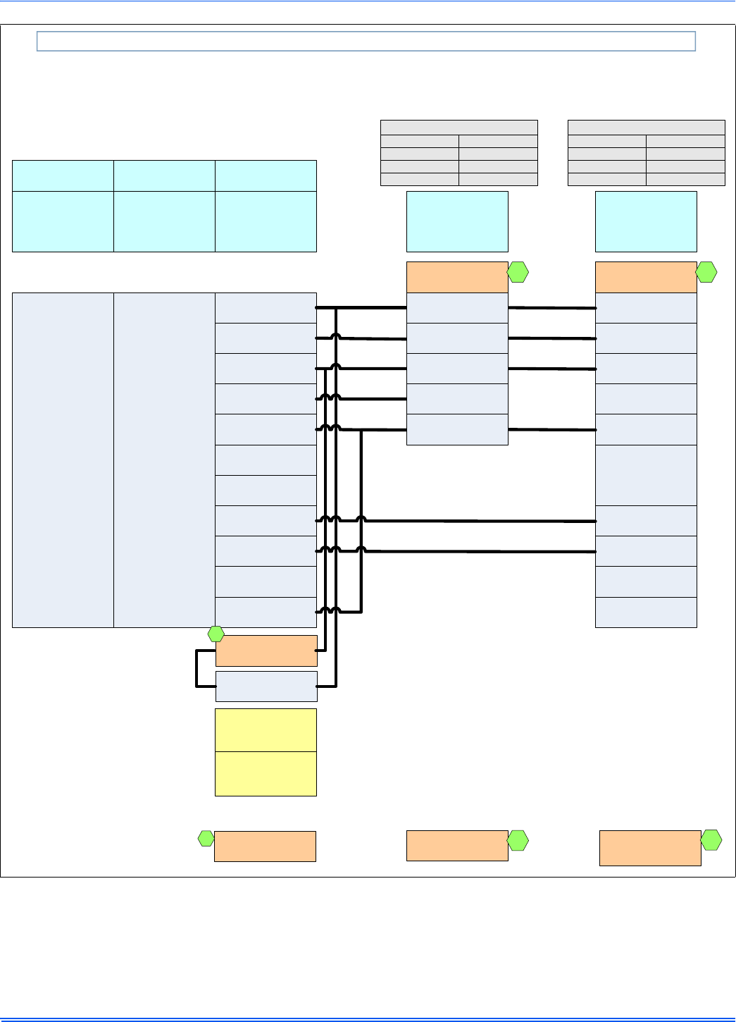
FIGURE 18: Thermostat Chart - Single Stage HP with Single Stage PSC Furnaces
HP 2C Single Stage Heat Pump – Single Stage PSC Furnace
C
24 – Volt Common
R
24 – Volt Hot
Y1
First Stage Compressor
O
Reversing Valve
Energized in Cool
L
Malfunction Light
G
Fan
*DP32H70124
THERMOSTAT
W1
Second Stage Aux. Heat
E
Emergency Heat
W2
Third Stage Heat
N/A
*BP21H50124
*BN21H00124
*DP21H40124
*DN21H00124
THERMOSTAT
N/A
*DN22U00124
THERMOSTAT
Part Numbers:
SAP = Legacy
67297 = 031-01975
E*B*
E*ZD
E*R*
OD MODELS
*HGD
HP*
*RHS
O
Reversing Valve
Energized in Cool
C
24 – Volt Common
R
24 – Volt Hot
W1/66(out)
Heat
Y
Compressor
DEMAND DEFROST
CONTROL
X/L
Malfunction Light
W
Auxiliary Heat
SINGLE STAGE
HEAT PUMP
1
1
Part Number:
S1-2HU16700124
3
24VAC Humidifier
(Optional)
External Humidistat
(Optional)
Open on Humidity Rise
3
Y2
Second Stage Compressor
Step 9 of Thermostat
Installer / Configuration
Menu must be set to
Pump OFF
Step 1 of Thermostat
Installer / Configuration
Menu must be set to
Heat Pump 1
G8C
L(Y/M)8S
G*9F
G*(8/9)S
ID MODELS
(G/T)GLS
(G,T)G(8/9)S
LF8
GF(8/9)
C
24 – Volt Common
R
24 – Volt Hot
W
Full Stage Heat
SINGLE STAGE PSC
FURNACE
G
Fan
SINGLE STAGE
PSC
FURNACE
Other Part Numbers:
SAP = Legacy
265901 = 031-09166
2
2
Y/Y2
Full Stage Compressor
356485-UIM-G-1211
Johnson Controls Unitary Products 15
ACCESSORY CONNECTIONS
The furnace control will allow power-switching control of various acces-
sories.
ELECTRONIC AIR CLEANER CONNECTION
Two 1/4” (0.64 cm) spade terminals (EAC and NEUTRAL) for electronic
air cleaner connections are located on the control board. The terminals
provide 115 VAC (1.0 amp maximum) during circulating blower opera-
tion.
HUMIDIFIER CONNECTION
Two 1/4” (0.64 cm) spade terminals (HUM and NEUTRAL) for humidi-
fier connections are located on the control board. The terminals provide
115 VAC (1.0 amp maximum) during heating system operation.
A mounting hole is provided on the control panel next to the furnace
control board for mounting a humidifier transformer if required.
SECTION VI: TWINNING AND STAGING
In applications where more heating capacity or more airflow capacity is
needed than what one furnace can deliver, twinning can be used to
make two furnaces operate in tandem. When two furnaces are installed
using the same duct system, it is very important that the two furnace cir-
culating air blowers operate in unison. If one blower starts before the
second blower, the duct system will become pressurized and the blower
on the second furnace will turn backwards causing the second furnace
to overheat, resulting in damage to the furnace. Twinning is used to
make two furnaces operate in tandem, using one duct system, one
room thermostat and causing both furnaces to turn on and off simulta-
neously.
TWINNING DUCT SYSTEM
Twinned furnaces must only be applied on a common duct system. A
single air supply plenum must be used for both furnaces and coil(s).
Separate plenums and supply ducts systems cannot be utilized. A sin-
gle return air plenum, common to both furnaces must be used. It is sug-
gested that a return platform be utilized, with bottom air entrance into
each furnace. If a side entrance returns system is used, the common
return duct must be divided equally so as to supply each furnace with
an equal amount of return air.
Both furnaces must be identical models in both heating capacity and
CFM capacity. Both furnaces must be operated on the same motor
speed tap. See typical application, Figure 19.
If furnace staging is desired with two single stage furnaces on a com-
mon duct, where the gas burner on the first furnace operates on W1
and the gas burner on the second furnace operates on W2, then the
use of an air-mixing device in the plenum to mix the air from both fur-
naces is strongly recommended. The mixing device must be installed
before any ducts that supply air to occupied spaces. Twinning causes
both indoor fans to operate simultaneously. If a mixing device is not
used, any ducts that are connected down stream from the furnace that
operates on W2, will be supplying cold air in the Heating mode to the
occupied spaces unless W2 is energized.
GAS PIPING
Furnace gas supplies must be provided as specified with these instruc-
tions. Since the furnaces are side by side, with no space between, gas
supplies must enter on the right and left respectively. All gas piping
must be in accordance with the national fuel gas code, ANSI Z223.1,
latest edition, and/or all local code or utility requirements.
TWINNING
In applications where more heating capacity or more airflow capacity is
needed than what one furnace can deliver, twinning can be used to
make two furnaces operate in tandem, using one duct system and one
room thermostat. When one duct system is used for two furnaces, it is
necessary that the two blowers operate in unison. The twinning function
of the board in this furnace ensures that both blowers turn on and off
simultaneously, and operate on the same blower speed.
Single-Wire Twinning
The control in the furnace has the single-wire twinning feature. With this
feature, a single wire is connected between the TWIN terminal on one
furnace board to the TWIN terminal on the second furnace board. The
board then communicates the blower status from one furnace to the
other along this wire. This communication makes the second furnace
blower come on at the same time, and on the same speed, as the first
furnace blower. To ensure stable communication, the common terminal
of each control must be connected.
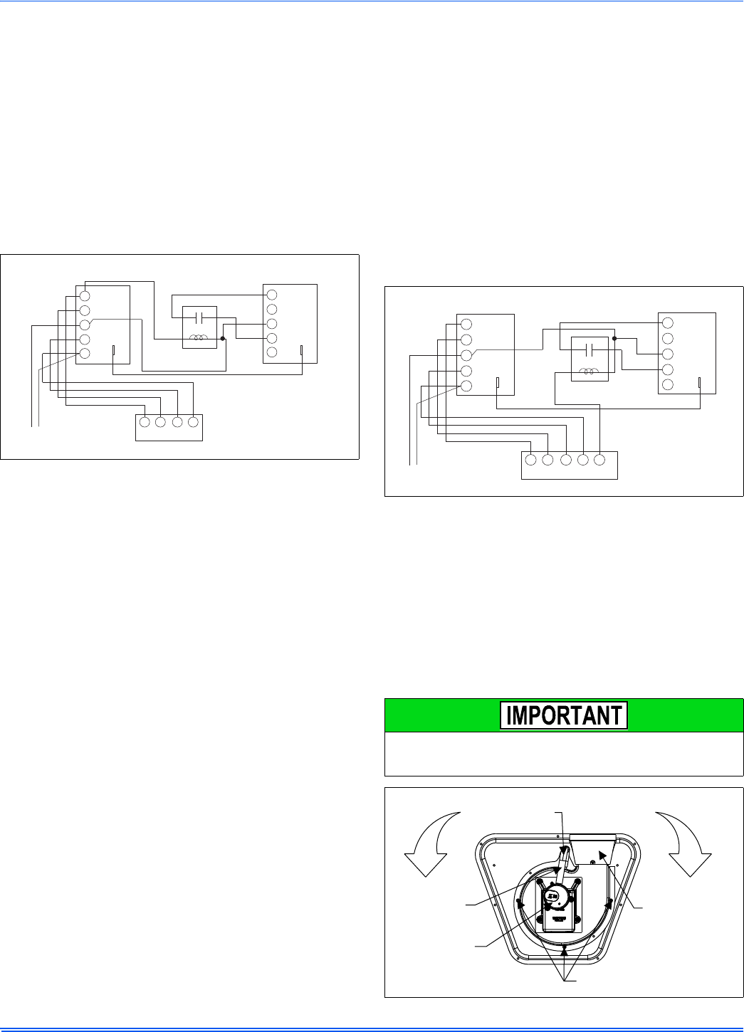
Single-Wire Twinning Instructions
Connect the control wiring as shown in Figure 21.
1. Connect the low voltage wiring from the wall thermostat to the ter-
minal strip on the control board of Furnace #1.
2. Connect a wire from the TWIN terminal of Furnace #1 to the TWIN
terminal of Furnace #2.
3. Install a separate 24V relay as shown in the diagram below. Use of
this relay is required, as it ensures that the transformers of the two
furnaces are isolated, thus preventing the possibility of any safety
devices being bypassed.
4. Connect the common wires of furnace #1 to the common terminal
of furnace #2.
Before installing the relay and wiring, disconnect electrical power to
both furnaces. Failure to cut power could result in electrical shock
or equipment damage.
The relay must not be installed in any location where it could be
exposed to water. If the relay has been exposed to water in any
way, it must not be used.
FIGURE 19: Typical Twinned Furnace Application
When two furnaces are twinned, typical system total airflow will be
approximately 85% of additive individual furnaces, i.e., two 2000
CFM units will yield a total 3400 CFM.
If a return duct is connected to only one furnace (with a connection
between the two furnaces) an imbalance in the airflow will occur
and the furnace furthest from the return plenum will overheat.
Vent Pipe
Electrical
Supply
Gas Supply
(Both sides)
1 Coil for
Each Furnace
COMMON
SUPPLY
PLENUM
Supply
Air
356485-UIM-G-1211
16 Johnson Controls Unitary Products
Single-Wire Twinning Operation
Heating - On a call for heat (W signal) from the wall thermostat, both
furnaces will start the ignition sequence and the burners on both fur-
naces will light. About thirty seconds after the burners light, the blowers
on both furnaces will come on in heating speed. When the thermostat is
satisfied, the burners will all shut off and, after the selected blower off
delay time, both blowers will shut off at the same time. The twinning
control ensures that both blowers come on and shut off at the same
time.
Cooling - On a call for cooling (Y signal) from the wall thermostat, both
furnace blowers will come on at the same time in cooling speed. When
the thermostat is satisfied, both blowers will stay on for 60 seconds,
then will shut off at the same time.
Continuous Fan - On a thermostat call for continuous fan (G signal),
both furnace blowers will come on at the same time in cooling speed
and will stay on until the G signal is removed.
STAGING
This control can also be used along with a two-stage wall thermostat to
stage two twinned furnaces, making them operate like a single two-
stage furnace. This allows only one furnace to supply heat during times
when the heat output from one furnace is sufficient to satisfy the
demand. When one duct system is used for two furnaces, it is neces-
sary that the two blowers operate in unison. The twinning function of
this board ensures that both blowers turn on and off simultaneously,
and operate on the same blower speed. Even when only one furnace is
supplying heat, both furnace blowers must run.
Single-Wire Staging
The single-wire twinning feature of this board can also be used for stag-
ing of two furnaces. With this feature, a single wire is connected
between the TWIN terminal on one furnace board to the TWIN terminal
on the second furnace board. The board then communicates the blower
status from one furnace to the other along this wire. This communica-
tion makes the second furnace blower come on at the same time, and
on the same speed, as the first furnace blower. To ensure stable com-
munication, the common terminal of each control must be connected.
Single-Wire Staging Instructions
Connect the control wiring as shown in Figure 22.
1. Connect the low voltage wiring from the wall thermostat to the ter-
minal strip on the control board of Furnace #1. For staging applica-
tions, the wire from thermostat W1 is connected to the W
connection on the board on Furnace #1. The wire from thermostat
W2 is connected to Furnace #2 through a separate relay, as
described below.
2. Connect a wire from the TWIN terminal of Furnace #1 to the TWIN
terminal of Furnace #2.
3. Install a separate 24V relay as shown in the diagram below. Use of
this relay is required, as it ensures that the transformers of the two
furnaces are isolated, thus preventing the possibility of any safety
devices being bypassed.
4. Connect the common between furnace #1 and furnace #2.
Single-Wire Staging Operation
Heating - On a call for first-stage heat (W1 signal) from the wall thermo-
stat, Furnace #1 will start the ignition sequence and the burners will
light. About thirty seconds after the burners light, the blowers on both
furnaces will come on in heating speed. When the thermostat is satis-
fied, the burners will shut off and, after the selected blower off delay
time, both blowers will shut off at the same time. On a call for second
stage of heat, the burners of Furnace #2 will also light and both blowers
will run. The twinning control ensures that both blowers come on and
shut off at the same time.
Cooling - On a call for cooling (Y signal) from the wall thermostat, both
furnace blowers will come on at the same time. When the thermostat is
satisfied, both blowers will stay on for 60 seconds, then will shut off at
the same time.
Continuous Fan - On a thermostat call for continuous fan (G signal),
both furnace blowers will come on at the same time in cooling speed
and will stay on until the G signal is removed.
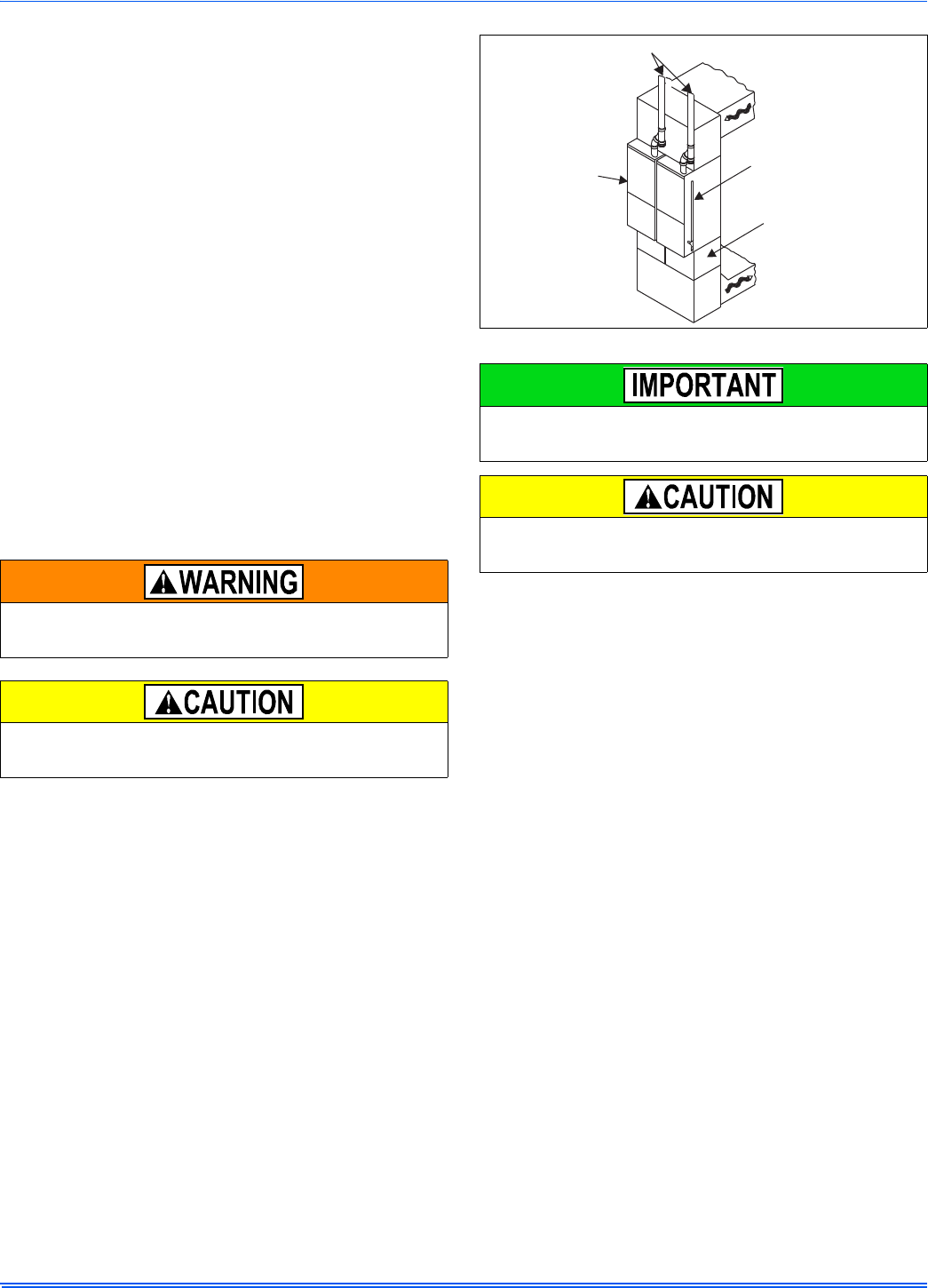
SECTION VII: VENT SYSTEM
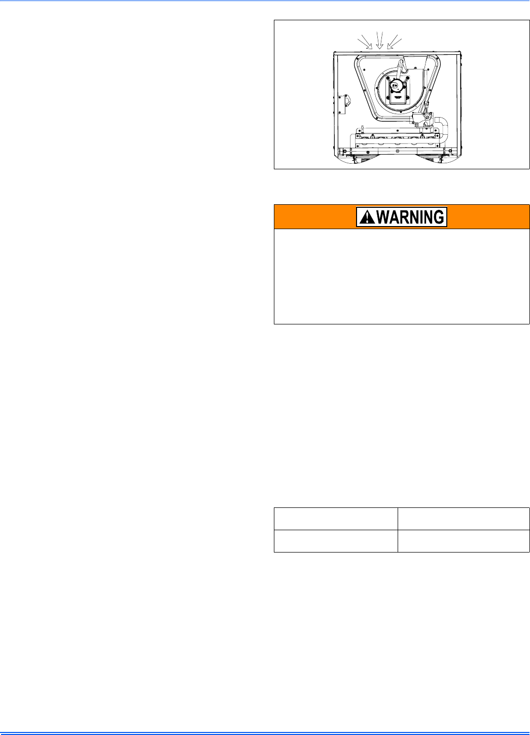
VENT CONNECTIONS
All models are provided with a flue transition that is sized for 4” diame-
ter vent connections. If a larger size vent connector is required, that
connection must be installed external to the furnace. Figure 22 shows
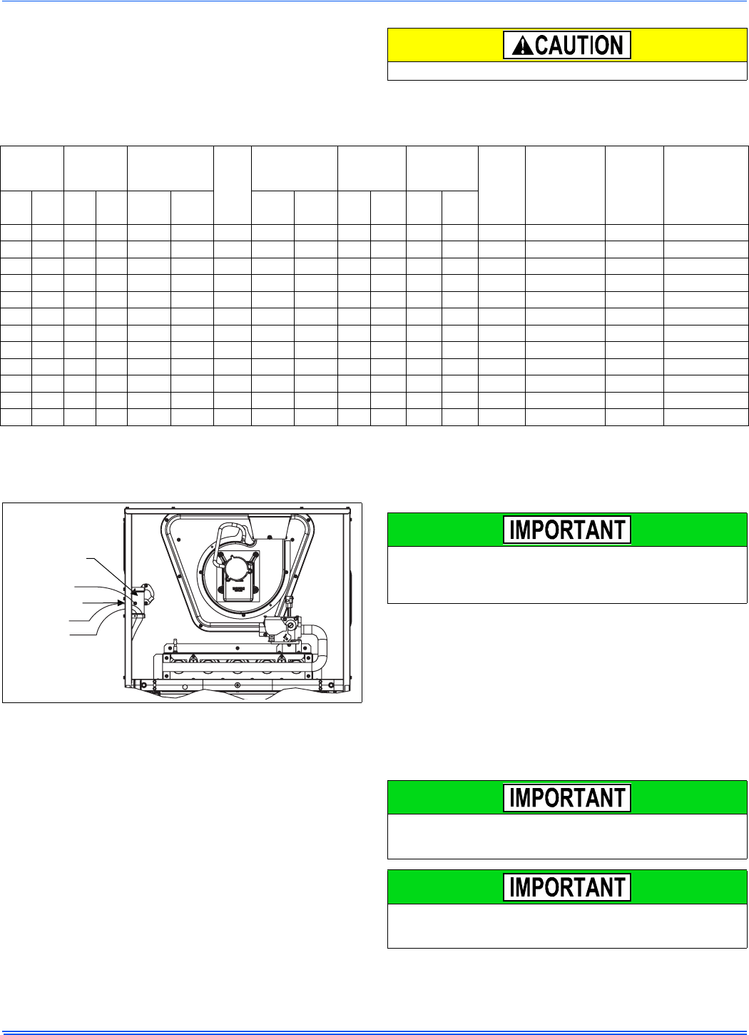
the furnace as it is shipped from the factory. To convert to a horizontal
or downflow position, remove the four screws that secure the inducer
assembly and rotate 90° being careful not to damage the gasket. Rein-
stall screws. Remove cap from appropriate vent outlet location on the
cabinet, cut insulation in cabinet to same size as the hole provided and
reinstall cap in the hole in the top panel.
FIGURE 20: Single Wire Twinning Wiring Diagram
W
G
C
R
Y
TWIN
TO A/C
WALL THERMOSTAT
WG RY
ISOLATION
RELAY
FURNACE 2
CONTROL BOARD
W
G
C
R
Y
TWIN
FURNACE 1
CONTROL BOARD
FIGURE 21: Single Wire Staging Wiring Diagram
In downflow applications, do not block the combustion air inlet. The
furnace must be installed on a coil cabinet or subbase to allow com-
bustion air to enter the burner compartment.
FIGURE 22: Combustion Air Inducer
W
G
C
R
Y
TWIN
TO A/C
WALL THERMOSTAT
W1 G RY
ISOLATION
RELAY
FURNACE 2
CONTROL BOARD
W
G
C
R
Y
TWIN
FURNACE 1
CONTROL BOARD
W2
COMBUSTION AIR INDUCER
90° 90°
Mounting Screw
(Remove)
Flue Transition
(Do Not Remove)
Mounting Screw
(Remove)
Pressure
Switch
Pressure Switch
Tube Routing
356485-UIM-G-1211
Johnson Controls Unitary Products 17
CATEGORY 1 - 450 F. MAX. VENT TEMP.
The venting system must be installed in accordance with Section 5.3,
Air for Combustion and Ventilation, of the National Fuel Gas Code
Z223.1/NFPA 54 (latest edition), or Sections 7.2, 7.3 or 7.4 of CSA
B149.1, National Gas and Propane Codes (latest edition) or applicable
provisions of the local building code and these instructions.
The furnace shall be connected to any type of B, BW or L vent connec-
tor, and shall be connected to a factory-built or masonry chimney. The
furnace shall not be connected to a chimney flue serving a sepa-
rate appliance designed to burn solid fuel.
It is recommended that the appliance is installed in a location where the
space temperature is 32 °F (0°C) or higher. If the appliance is installed
in a location where the ambient temperature is below 32 °F (0°C), the
combustion byproducts could condense causing damage to the appli-
ance heat exchanger.
This appliance may be common vented with another gas appliance for
residential installations as allowed by the codes and standards listed in
these instructions.
Non-HUD approved Modular Homes must be vented with an approved
roof jack and may not be common vented with other appliances.
VENTING
Category I venting consists of vertically venting one or more appliances
in B-vent or masonry chimney (as allowed), using single wall metal pipe
or B-vent connectors. Type B-vent system extends in a general vertical
direction and does not contain offsets exceeding 45°. A vent system
having not more than one 60° offset is permitted.
VENTING INTO AN EXISTING CHIMNEY
For Category I installations, the furnace shall be connected to a factory
built chimney or vent complying with a recognized standard, or a
masonry or concrete chimney lined with a material acceptable to the
authority having jurisdiction. Venting into an unlined masonry chimney
or concrete chimney is prohibited.
Where use of an existing chimney is unavoidable, the following rules
must be followed:
1. The masonry chimney must be built and installed in accordance
with nationally recognized building codes or standards and must
be lined with approved fire clay tile flue liners or other approved
liner material that will resist corrosion, softening, or cracking from
flue gases. THIS FURNACE IS NOT TO BE VENTED INTO AN
UNLINED MASONRY CHIMNEY.
2. This furnace must be vented into a fire clay tile lined masonry
chimney only if a source of dilution air is provided, such as by com-
mon venting with a draft hood equipped water heater. If no source
of dilution air is available, Type B vent must be used, or masonry
chimney vent kit 1CK0603 or 1CK0604 must be used. Refer to the
instructions with the kit to properly apply these masonry chimney
kits.
3. The chimney must extend at least 3 ft (0.91 m) above the highest
point where it passes through a roof of a building and at least two
feet higher than any portion of the building with a horizontal dis-
tance of ten feet.
4. The chimney must extend at least 5 ft (1.5 m) above the highest
equipment draft hood or flue collar.
FAN-ASSISTED COMBUSTION SYSTEM
This appliance is equipped with an integral mechanical means to either
draw products of combustion through the heat exchanger.
Ambient Combustion Air Supply
This type installation will draw the air required for combustion from
within the space surrounding the appliance and from areas or rooms
adjacent to the space surrounding the appliance. This may be from
within the space in a non-confined location or it may be brought into the
furnace area from outdoors through permanent openings or ducts. A
single, properly sized pipe from the furnace vent connector to the out-
doors must be provided. Combustion air is brought into the furnace
through the unit top panel opening.
An unconfined space is not less than 50 cu.ft (1.42 m3) per 1,000 Btu/
hr (0.2928 kW) input rating for all of the appliances installed in that
area.
Rooms communicating directly with the space containing the appli-
ances are considered part of the unconfined space, if doors are fur-
nished with openings or louvers.
A confined space is an area with less than 50 cu.ft (1.42 m3) per 1,000
Btu/hr (0.2928 kW) input rating for all of the appliances installed in that
area. The following must be considered to obtain proper air for combus-
tion and ventilation in confined spaces.
Combustion Air Source From Outdoors
The blocking effects of louvers, grilles and screens must be given con-
sideration in calculating free area. If the free area of a specific louver or
grille is not known, refer to Table 7, to estimate free area.
* Do not use less than 1/4”(0.635 cm) mesh
+ Free area of louvers and grille varies widely; the installer should follow
louver or grille manufacturer’s instructions.
Dampers, Louvers and Grilles (Canada Only)
1. The free area of a supply air opening shall be calculated by sub-
tracting the blockage area of all fixed louvers grilles or screens
from the gross area of the opening.
2. Apertures in a fixed louver, a grille, or screen shall have no dimen-
sion smaller than 0.25” (0.64 cm).
3. A manually operated damper or manually adjustable louvers are
not permitted for use.
4. A automatically operated damper or automatically adjustable lou-
vers shall be interlocked so that the main burner cannot operate
unless either the damper or the louver is in the fully open position.
FIGURE 23: Combustion Airflow Path Through The Furnace Casing to
the Burner Compartment
This type of installation requires that the supply air to the appli-
ance(s) be of a sufficient amount to support all of the appliance(s)
in the area. Operation of a mechanical exhaust, such as an exhaust
fan, kitchen ventilation system, clothes dryer or fireplace may cre-
ate conditions requiring special attention to avoid unsatisfactory
operation of gas appliances. A venting problem or a lack of supply
air will result in a hazardous condition, which can cause the appli-
ance to soot and generate dangerous levels of CARBON MONOX-
IDE, which can lead to serious injury, property damage and / or
death.
Table 7: Estimated Free Area
Wood or Metal
Louvers or Grilles
Wood 20-25%*
Metal 60-70% *
Screens+ 1/4” (0.635 cm)
mesh or larger 100%
Combustion Air
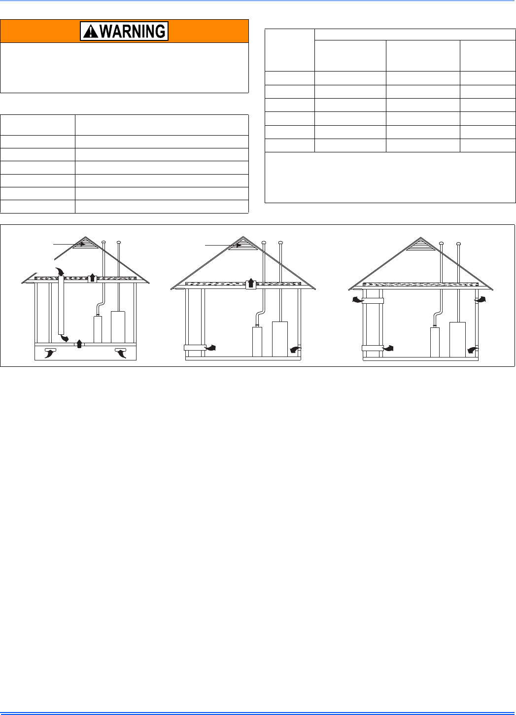
356485-UIM-G-1211
18 Johnson Controls Unitary Products
Air Supply Openings and Ducts
1. An opening may be used in lieu of a duct to provide the outside air
supply to an appliance unless otherwise permitted by the authority
having jurisdiction. The opening shall be located within 12” (30.5
cm) horizontally from, the burner level of the appliance. Refer to
“COMBUSTION AIR SOURCE FROM OUTDOORS and VENT
AND SUPPLY AIR SAFETY CHECK” in these instructions for
additional information and safety check procedure.
2. The duct shall be either metal, or a material meeting the class 1
requirements of CAN4-S110 Standard for Air Ducts.
3. The duct shall be least the same cross-sectional area as the free
area of the air supply inlet opening to which it connects.
4. The duct shall terminate within 12 in (30.5 cm) above, and within
24 in (61 cm) horizontally from, the burner level of the appliance
having the largest input.
5. A square or rectangular shaped duct shall only be used when the
required free area of the supply opening is 9 in2 (58.06 cm2) or
larger. When a square or rectangular duct is used, its small dimen-
sion shall not be less than 3 in (7.6 cm).
6. An air inlet supply from outdoors shall be equipped with a means
to prevent the direct entry of rain and wind. Such means shall not
reduce the required free area of the air supply opening.
7. An air supply inlet opening from the outdoors shall be located not
less than 12” (30.5 cm) above the outside grade level.
Combustion Air Source from Outdoors
1. Two permanent openings, one within 12 in (30.5 mm) of the top
and one within 12 in (30.5 mm) of bottom of the confined space,
Two permanent openings, shall communicate directly or by means
of ducts with the outdoors, crawl spaces or attic spaces.
2. One permanent openings, commencing within 12 in (30.5 mm) of
the top of the enclosure shall be permitted where the equipment
has clearances of at least 1 in (2.54 cm) from the sides and back
and 6 in (15.24 cm) from the front of the appliance. The opening
shall communicate directly with the outdoors and shall have a min-
imum free area of:
a. 1 square in per 3000 Btu per hour (6.45 cm3 per 0.879 kW) of
the total input rating of all equipment located in the enclosure.
b. Not less than the sum of all vent connectors in the confined
space.
3. The duct shall be least the same cross-sectional area as the free
area of the air supply inlet opening to which it connects.
4. The blocking effects of louvers, grilles and screens must be given
consideration in calculating free area. If the free area of a specific
louver or grille is not known. Refer to Table 7 to estimate free area.
Ventilated Combustion Air
The ventilated attic space or a crawl space from which the combustion
air is taken must comply with the requirements specified in “AIR
SOURCE FROM OUTDOORS” in this instruction or in Section 5.3, Air
for Combustion and Ventilation of the National Fuel Gas Code, ANSI
Z223.1 (latest edition). This type installation requires two properly sized
pipes. One brings combustion air from a properly ventilated attic space
or crawl space and a second pipe that extends from the furnace vent
connection (top right of unit) to the exterior of the building.
Vent and Supply (Outside) Air Safety Check Procedure
For Category I furnaces, vent installations shall be in accordance with
Parts 7 and 11 of the National Fuel Gas Code, ANSI Z223.1/NFPA 54,
and or Section 7 and Appendix B of the CSA B149.1, Natural Gas and
Propane Installation Codes, the local building codes, furnace and vent
manufacture's instructions.
When a Category I furnace is removed or replaced, the original
venting system may no longer be correctly sized to properly vent
the attached appliances.
An improperly sized vent system can cause CARBON MONOXIDE
to spill into the living space causing personal injury, and or death.
Table 8: Unconfined Space Minimum Area
BTUH Input Rating Minimum Free Area
Required for Each Opening
40,000 40 in2 (258 cm2)
60,000 60 in2 (387 cm2)
80,000 80 in2 (516 cm2)
100,000 100 in2 (645 cm2)
120,000 120 in2 (742 cm2)
130,000 130 in2 (838 cm2)
Table 9: Free Area
BTUH Input
Rating
Minimum Free Area Required for Each Opening
Horizontal Duct
(2,000 BTUH)
Vertical Duct or
Opening to Outside
(4,000 BTUH)
Round Duct
(4,000 BTUH)
40,000 20 in2 (129 cm2)10 in
2 (64 cm2)4” (10 cm)
60,000 30 in2 (193 cm2)15 in
2 (97 cm2)5” (13 cm)
80,000 40 in2 (258 cm2) 20 in2 (129 cm2)5” (13 cm)
100,000 50 in2 (322 cm2) 25 in2 (161 cm2)6” (15 cm)
120,000 60 in2 (387 cm2) 30 in2 (193 cm2)7” (18 cm)
130,000 65 in2 (419 cm2) 33 in2 (213 cm2)7” (18 cm)
EXAMPLE: Determining Free Area.
Appliance 1 Appliance 2 Total Input
100,000 + 30,000 = (130,000 4,000) = 32.5 Sq. In. Vertical
Appliance 1 Appliance 2 Total Input
100,000 + 30,000 = (130,000 2,000) = 65 Sq. In. Horizontal
FIGURE 24: Outside and Ambient Combustion Air
Gable
Vent
Gas
Vent
Soffit
Vent
Ventilated
Attic
Top Above
Insulation
Optional
Inlet (a)
Outlet
Air (a)
Ventilated
Crawl Space
Gas
Water
Heater
Furnace
Soffit
Vent
Gas
Water
Heater Inlet
Air (a)
Inlet
Air (b)
Furnace
Gas
Vent
Outlet
Air (a)
Outlet
Air (b)
Inlet
Air (a)
Inlet
Air (b)
Gas
Water
Heater
Furnace
Ventilated
Attic
Top Above
Insulation
Gable
Vent
Gas
Vent
356485-UIM-G-1211
Johnson Controls Unitary Products 19
Multi-story or common venting systems are permitted and must be
installed in accordance with the National Fuel Gas Code, ANSI Z223.1/
NFPA 54 and / or the CSA B149.1, Natural Gas and Propane Installa-
tion Codes, local codes, and the manufacture's instructions.
Vent connectors serving Category I furnaces shall not be connected
into any portion of mechanical draft systems operating under positive
pressure.
Horizontal portions of the venting system shall be supported to prevent
sagging using hangers or perforated straps and must slope upwards
not less than 1/4" per foot (0.635 cm/m) from the furnace to the vent ter-
minal.
It is recommended that you follow the venting safety procedure below.
This procedure is designed to detect an inadequate ventilation system
that can cause the appliances in the area to operate improperly causing
unsafe levels of Carbon Monoxide or an unsafe condition to occur.
SECTION VIII: START-UP AND
ADJUSTMENTS
The initial start-up of the furnace requires the following additional
procedures:
When the gas supply is initially connected to the furnace, the gas piping
may be full of air. In order to purge this air, it is recommended that the
ground union be loosened until the odor of gas is detected. When gas is
detected, immediately retighten the union and check for leaks. Allow
five minutes for any gas to dissipate before continuing with the start-up
procedure. Be sure proper ventilation is available to dilute and carry
away any vented gas.
NOx SCREEN REMOVAL (Lo-NOx Models Only)
If the furnace is equipped with NOx screens and is to be used with LP
(propane) gas, the screens must be removed prior to start-up.
1. Make sure that the electrical power to the unit is turned off and that
the gas supply is turned off at the shut-off valve.
2. Remove the blower compartment and burner compartment access
doors.
3. Disconnect the gas supply piping at the union to permit removal of
the entire burner and gas control assembly from the vestibule
panel. Use the wrench boss on the gas valve when removing or
installing the piping.
4. Unplug the igniter from the wire harness. Disconnect the flame
sensor wires located on top of the air shield. Unplug the gas valve
from the wiring harness.
5. Remove the screws holding the burner assembly to the vestibule
panel.
6. Remove the burner assembly. It should be possible to swing the
burner assembly out of the way without disconnecting the remain-
ing wires.
7. With the burner assembly out of the way, simply slide the NOx
screens out of the heat exchanger tubes and discard the screens.
8. Replace all components in reverse order. Reconnect all wiring.
CARBON MONOXIDE POISONING HAZARD
Failure to follow the steps outlined below for each appliance connected to the venting system being placed into operation could result in carbon-
monxide poisoning or death.
The following steps shall be followed for each appliance connected to the venting system being placed into operation, while all other appliances
connected to the venting system are not in operation:
1. Inspect the venting system for proper size and horizontal pitch. Determine that there is no blockage, restriction, leakage, corrosion or other
deficiencies, which could cause an unsafe condition
2. Close all building doors and windows.
3. Turn on clothes dryers and TURN ON any exhaust fans, such as range hoods and bathroom exhausts, so they shall operate at maximum
speed. Open the fireplace dampers. Do not operate a summer exhaust fan.
4. Follow the lighting instructions. Place the appliance being inspected in operation. Adjust thermostat so the appliance shall operate contin-
uously.
5. Test each appliance (such as a water heater) equipped with a draft hood for spillage (down-draft or no draft) at the draft hood relief opening
after 5 minutes of main burner operation. Appliances that do not have draft hoods need to be checked at the vent pipe as close to the
appliance as possible. Use a combustion analyzer to check the CO2 and CO levels of each appliance. Use a draft gauge to check for a
downdraft or inadequate draft condition.
6. After it has been determined that each appliance properly vents when tested as outlined above, return doors, windows, exhaust fans, fire-
place dampers and any other gas burning appliance to their normal condition.
7. If improper venting is observed during any of the above tests, a problem exists with either the venting system or the appliance does not
have enough combustion air (Supply Air from outside) to complete combustion. This condition must be corrected before the appliance can
function safely.
NOTE: An unsafe condition exists when the CO reading exceeds 40 ppm and the draft reading is not in excess of - 0.1 in. W.C. (-25 kPa) with
all of the appliance(s) operating at the same time.
8. Any corrections to the venting system and / or to the supply (outside) air system must be in accordance with the National Fuel Gas Code
Z223.1 or CAN/CGA B149.1 Natural Gas and Propane Installation Code (latest editions). If the vent system must be resized, follow the
appropriate tables in Appendix G of the above codes or for this appliance.
All electrical connections made in the field and in the factory should
be checked for proper tightness.
356485-UIM-G-1211
20 Johnson Controls Unitary Products
GAS PIPING LEAK CHECK
It is recommended that when the gas supply is first connected to the
furnace, the ground union be loosened until the odor of gas is detected.
When gas is detected, immediately tighten the union and check for gas
leaks. Allow five minutes for any gas to dissipate before continuing with
the start-up procedure. Be sure that proper ventilation is available to
dilute and carry away any vented gas.
With furnace in operation, check all of the pipe joints, gas valve connec-
tions and manual valve connections for leakage using an approved gas
detector, a non-corrosive leak detection fluid or other leak detection
methods. Take appropriate action to stop any leak. If a leak persists,
replace the faulty component.
The furnace and its equipment shut-off valve must be disconnected
from the gas supply during any pressure testing of that system at test
pressures in excess of 1/2 PSI (3.45 kPa).
The furnace must be isolated from the gas supply piping system by
closing the equipment shut-off valve during any pressure testing of the
gas supply system.
IGNITION SYSTEM SEQUENCE
1. Turn the gas supply ON at external valve and main gas valve.
2. Set the thermostat above room temperature to call for heat.
3. System start-up will occur as follows:
a. The induced draft blower motor will start and come up to
speed. Shortly after inducer start-up, the hot surface igniter
will glow for about 17 seconds.
b. After this warm up, the ignition module will energize (open)
the main gas valve.
c. After flame is established, the supply air blower will start in
about 30 seconds.
With furnace in operation, check all of the pipe joints, gas valve connec-
tions and manual valve connections for leakage using an approved gas
detector, a non-corrosive leak detection fluid, or other leak detection
methods. Take appropriate steps to stop any leak. If a leak persists,
replace the component.
CALCULATING THE FURNACE INPUT
(NATURAL GAS)
Verify natural gas input rate by clocking meter.
1. Turn off all other gas appliances and pilots.
2. Run furnace for a minimum of 3 minutes in heating operation.
3. Measure time (in sec) for gas meter to complete 1 revolution and
note reading. The 2 cubic feet dial provides a more accurate mea-
surement of gas flow.
4. Refer to Table 10 for cubic feet of gas per hour.
5. Multiply cubic feet per hour by heating valve (BTU/cu ft) to obtain
input.
If clocked rate does not match the input rate from the unit nameplate.
follow steps in next section to adjust the manifold pressure. Repeat
steps 2 - 5 until correct input is achieved.
FIRE OR EXPLOSION HAZARD
Failure to follow the safety warnings exactly could result in serious
injury, death or property damage.
Never test for gas leaks with an open flame. Use a commercially
available soap solution made specifically for the detection of leaks
to check all connections. A fire or explosion may result causing
property damage, personal injury or loss of life.
Burner ignition may not be satisfactory on first startup due to resid-
ual air in the gas line or until gas manifold pressure is adjusted. The
ignition control will make three attempts to light before locking out.
Burner ignition may not be satisfactory on first startup due to resi-
dential air in the gas line or until gas manifold pressure is adjusted.
The ignition control will make 3 attempts to light before locking out.
Burner orifices are sized to provide proper input rate using natural
gas with a heating value of 1030 BTU/Ft3 (38.4 MJ/m3). If the heat-
ing value of your gas is significantly different, it may be necessary
to replace the orifices.
If orifice hole appears damaged or it is suspected to have been
redrilled, check orifice hole with a numbered drill bit of correct size.
Never redrill an orifice. A burr-free and sqaurely aligned orifice hole
is essential for proper flame characteristics.
DO NOT bottom out gas valve regulator adjusting screw. This can
result in unregulated manifold pressure and result in excess over-
fire and heat exchanger failures.
DO NOT set manifold pressure less than 3.2 in wc or more than 3.8
in wc for natural gas at sea level. If manifold pressure is outside this
range, change main burner orifices.
Be sure to relight any gas appliances that were turned off at the
start of this input check.
NOTICE
NOTICE
NOTICE
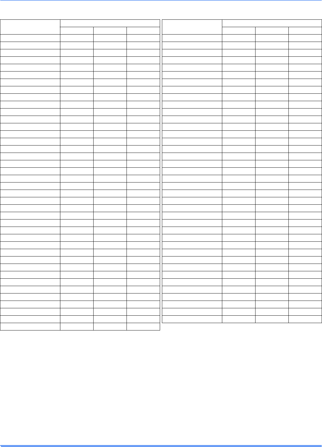
356485-UIM-G-1211
Johnson Controls Unitary Products 21
Table 10: Gas Rate (CU FT/HR)
Seconds For
1 Revolution
Size of Test Dial Seconds For
1 Revolution
Size of Test Dial
1 Cu Ft 2 Cu Ft 5 Cu Ft 1 Cu Ft 2 Cu Ft 5 Cu Ft
10 360 720 1800 50 72 144 360
11 327 655 1636 51 71 141 355
12 300 600 1500 52 69 138 346
13 277 555 1385 53 68 136 340
14 257 514 1286 54 67 133 333
15 240 480 1200 55 65 131 327
16 225 450 1125 56 64 129 321
17 212 424 1059 57 63 126 316
18 200 400 1000 58 62 124 310
19 189 379 947 59 61 122 305
20 180 360 900 60 60 120 300
21 171 343 857 62 58 116 290
22 164 327 818 64 56 112 281
23 157 313 783 66 54 109 273
24 150 300 750 68 53 106 265
25 144 288 720 70 51 103 257
26 138 277 692 72 50 100 250
27 133 267 667 74 48 97 243
28 129 257 643 76 47 95 237
29 124 248 621 78 46 92 231
30 120 240 600 80 45 90 225
31 116 232 581 82 44 88 220
32 113 225 563 84 43 86 214
33 109 218 545 86 42 84 209
34 106 212 529 88 41 82 205
35 103 206 514 90 40 80 200
36 100 200 500 92 39 78 196
37 97 195 486 94 38 76 192
38 95 189 474 96 38 75 188
39 92 185 462 98 37 74 184
40 90 180 450 100 36 72 180
41 88 176 439 102 35 71 178
42 86 172 429 104 35 69 173
43 84 167 419 106 34 68 170
44 82 164 409 108 33 67 167
45 80 160 400 110 33 65 164
46 78 157 391 112 32 64 161
47 76 153 383 116 31 62 155
48 75 150 375 120 30 60 150
49 73 147 367
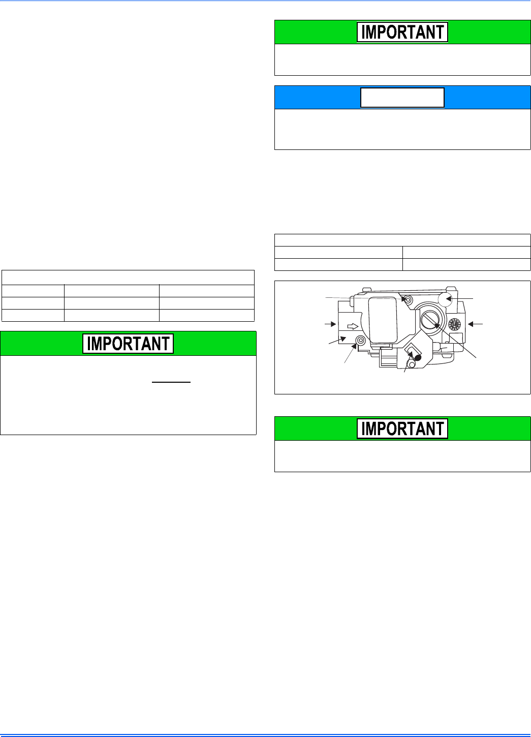
356485-UIM-G-1211
22 Johnson Controls Unitary Products
ADJUSTMENT OF MANIFOLD GAS PRESSURE &
INPUT RATE
Inlet and manifold gas pressure may be measured by connecting the
“U” tube manometer to the gas valve with a piece of tubing. Follow the
appropriate section in the instructions below. Refer to Figure 25 for a
drawing of the locations of the pressure ports on the gas valve.
Turn gas off at the ball valve or gas cock on gas supply line
before the gas valve. Find the pressure ports on the gas
valve marked Out P and In P.
1. The manifold pressure must be taken at the port marked OUT P.
2. The gas line pressure must be taken at the port marked IN P.
3. Using a 3/32” (2.4 mm) Allen wrench, loosen the set screw by turn-
ing it 1 turn counter clockwise. DO NOT REMOVE THE SET
SCREW FROM THE PRESSURE PORT.
Read the inlet gas pressure
Connect the positive side of the manometer to the IN P Tap on the gas
valve. Do not connect any tubing to the negative side of the manometer,
as it will reference atmospheric pressure. Refer to Figure 26 for connec-
tion details.
1. Turn gas and electrical supplies on and follow the operating
instructions to place the unit back in operation.
2. Once the correct gas inlet pressure has been established, see
Table 11, turn the gas valve to OFF and turn the electrical supply
switch to OFF; then remove the flexible tubing from the gas valve
pressure tap and tighten the pressure tap plug using the 3/32” (2.4
mm) allen wrench.
3. Turn the electrical and gas supplies back on, and with the burners
in operation, check for gas leakage around the gas valve pressure
port for leakage using an approved non-corrosive gas leak detec-
tion fluid, or other non-flammable leak detection methods.
Read the manifold gas pressure
Connect the positive side of the manometer to the adapter previously
installed in the OUT P Tap on the gas valve. Do not connect any tubing
to the negative side of the manometer, as it will reference atmospheric
pressure. Refer to Figure 26 for connection details.
1. Refer to Figure 25 for location of pressure regulator adjustment
cap and adjustment screws on main gas valve.
2. Turn gas and electrical supplies on and follow the operating
instructions to place the unit back in operation.
3. Adjust manifold pressure by adjusting gas valve regulator screw
for the appropriate gas per the following:
4. After the manifold pressure has been adjusted, re-calculate the
furnace input to make sure you have not exceeded the specified
input on the rating plate. Refer to “CALCULATING THE FURNACE
INPUT (NATURAL GAS)”.
5. Once the correct BTU (kW) input has been established, turn the
gas valve to OFF and turn the electrical supply switch to OFF; then
remove the flexible tubing from the gas valve pressure tap and
tighten the pressure tap plug using the 3/32” (2.4 mm) Allen
wrench.
6. Turn the electrical and gas supplies back on, and with the burners
in operation, check for gas leakage around the gas valve pressure
port for leakage using an approved non-corrosive gas leak detec-
tion fluid, or other non-flammable leak detection methods.
Table 11: Inlet Gas Pressure Range
INLET GAS PRESSURE RANGE
Natural Gas Propane (LP)
Minimum* 4.5” W.C. (1.12 kPa) 8.0” W.C. (1.99 kPa)
Maximum 10.5” W.C. (2.61 kPa) 13.0” (3.24 kPa) W.C.
The inlet gas pressure operating range table specifies what the
minimum and maximum gas line pressures must be for the furnace
to operate safely. The gas line pressure MUST BE a minimum of:
• 7” w.c. (1.74 kPA) for Natural Gas
• 11” w.c. (2.74 kPA) for Propane (LP) Gas
in order to obtain the BTU input specified on the rating plate and/or
the nominal manifold pressure specified in these instructions and
on the rating plate.
The cap for the pressure regulator must be removed to gain access
to the adjustment screw. Loosening or tightening the cap does not
adjust the flow of gas.
The regulated outlet pressures, both low and high, have been cali-
brated at the factory. Additional pressure adjustment should not be
necessary. If adjustment is necessary, set to the following specifica-
tions. After adjustment, check for gas leakage.
Table 12: Nominal Manifold Pressure
NOMINAL MANIFOLD PRESSURE
Natural Gas 3.5" w.c. (0.87 kPa)
Propane (LP) Gas 10.0" w.c. (2.488 kPa)
FIGURE 25: Gas Valve
If gas valve regulator is turned in (clockwise), manifold pressure is
increased. If screw is turned out (counter clockwise), manifold pres-
sure will decrease.
NOTICE
INLET
WRENCH
BOSS
INLET
PRESSURE
PORT
ON
OFF
ON/OFF SWITCH
(Shown in ON position)
MAIN REGULATOR
ADJUSTMENT
OUTLET
OUTLET
PRESSURE
PORT
VENT PORT
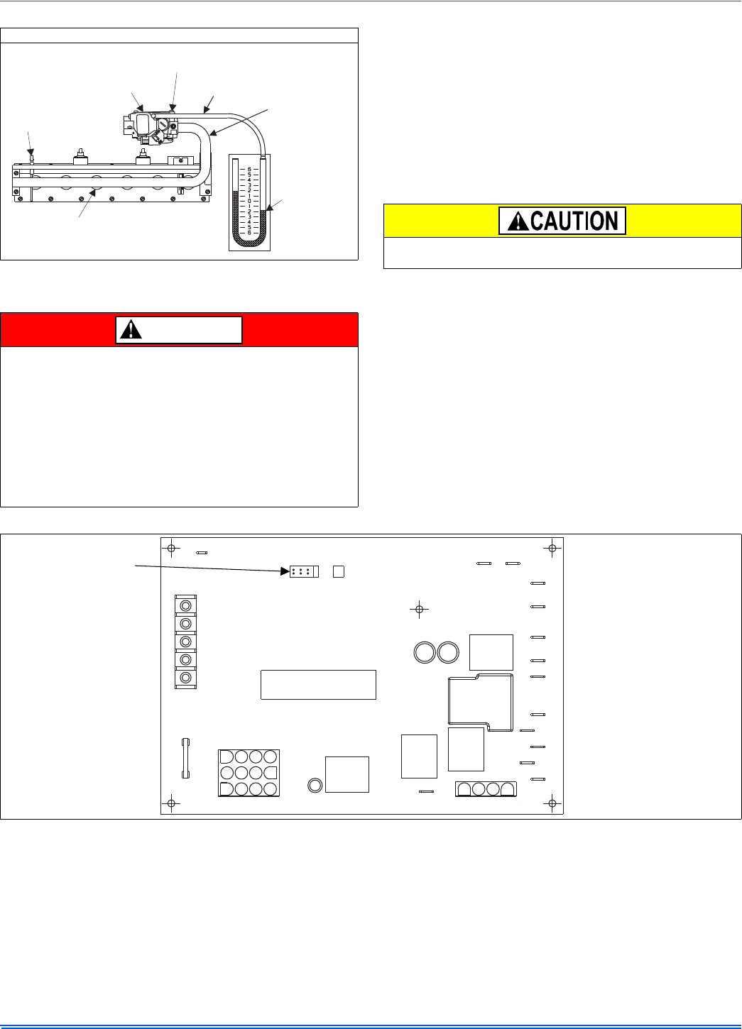
356485-UIM-G-1211
Johnson Controls Unitary Products 23
ADJUSTMENT OF TEMPERATURE RISE
After about 5 minutes of operation, determine the furnace temperature
rise. Take readings of both the return air and the heated air in the ducts,
about six feet (1.83 m) from the furnace where they will not be affected
by radiant heat. Increase the blower speed to decrease the temperature
rise; decrease the blower speed to increase the rise.
All direct-drive blowers have multi-speed motors. The blower motor
speed taps are located on the furnace control board in the blower com-
partment. Refer to Figure 27, and the unit-wiring label to change the
blower speed. To use the same speed tap for heating and cooling, the
heat terminal and cool terminal must be connected using a jumper wire
and connected to the desired motor lead. Place all unused motor leads
on park terminals. Two park terminals are provided.
ADJUSTMENT OF FAN CONTROL SETTINGS
This furnace is equipped with a time-on/time-off heating fan control. The
fan on delay is fixed at 30 seconds. The fan off delay has 4 settings (60,
90, 120 and 180 seconds). The fan off delay is factory set to 120 sec-
onds. The fan-off setting must be long enough to adequately cool the
furnace, but not so long that cold air is blown into the heated space. The
fan-off timing may be adjusted by positioning the jumper on two of the
four pins as shown in Figure 27.
MANIFOLD PRESSURE “U” TUBE CONNECTION
FIGURE 26: Reading Gas Pressure
The temperature rise, or temperature difference between the return
air and the supply (heated) air from the furnace, must be within the
range shown on the furnace rating plate and within the application
limitations shown in SECTION 6.
The supply air temperature cannot exceed the “Maximum Supply
Air Temperature” specified in these instructions and on the fur-
nace rating plate. Under NO circumstances can the furnace be
allowed to operate above the Maximum Supply Air Temperature.
Operating the furnace above the Maximum Supply Air Temperature
will cause premature heat exchanger failure, high levels of Carbon
Monoxide, a fire hazard, personal injury, property damage, and/or
death.
U-TUBE
MANOMETER
3.5 IN
WATER
COLUMN
GAS
PRESSURE
SHOWN
GAS
BURNERS
OUTLET
PRESSURE TAP
GAS VALVE
FLAME
SENSOR
1/4” TUBING
MAINIFOLD
PIPE
DANGER
Do not energize more than one motor speed at a time or damage to
the motor will result.
FIGURE 27: Furnace Control Board
PARK PARK
HI COOL
HEAT
EAC-H
L1
XFMR
NEUTRALS
HUM
TWIN
60
90
120
180
BLOWER
OFF
DELAY
Y/Y2
WRGC
Blower Off
Delay Timer
(In seconds)
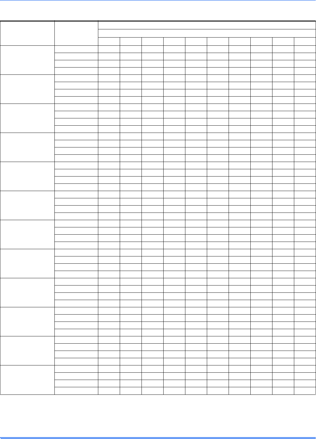
356485-UIM-G-1211
24 Johnson Controls Unitary Products
NOTES:
1. Airflow expressed in standard cubic feet per minute (CFM).
2. Motor voltage at 115 V.
Table 13: Blower Performance CFM - Any Position (without filter) - Bottom Return
Models Speed
Bottom Airflow Data (SCFM)
Ext. Static Pressure (in. H2O)
0.1 0.2 0.3 0.4 0.5 0.6 0.7 0.8 0.9 1.0
040A08
High 966 923 874 804 717 566 386 121 NA NA
Medium High 813 782 743 687 605 464 280 118 NA NA
Medium Low 745 706 667 619 545 413 205 NA NA NA
Low 684 655 614 565 489 342 171 NA NA NA
060A10
High 1292 1230 1160 1088 1004 891 760 476 129 129
Medium High 1203 1157 1105 1035 942 846 728 485 133 129
Medium Low 1043 1010 962 905 823 705 491 305 124 123
Low 869 845 811 772 708 579 438 178 145 125
060A12
High 1358 1341 1319 1303 1275 1238 1190 1130 1062 943
Medium High 1097 1083 1075 1064 1042 1024 997 962 906 821
Medium Low 935 928 920 899 872 840 809 771 731 659
Low 800 779 763 736 711 687 657 622 584 529
080B12
High 1329 1307 1285 1247 1195 1143 1091 1027 927 806
Medium High 994 1004 1008 984 970 941 893 839 773 669
Medium Low 786 790 782 781 761 743 726 685 630 540
Low 655 654 647 629 620 594 560 524 469 399
080C16
High 1881 1822 1783 1696 1602 1539 1465 1394 1267 1130
Medium High 1553 1535 1492 1456 1408 1343 1279 1226 1113 1014
Medium Low 1312 1286 1288 1260 1205 1143 1091 1029 966 841
Low 1169 1166 1128 1098 1069 1032 987 909 835 747
080C22
High 2811 2725 2638 2540 2448 2339 2224 2111 1974 1831
Medium High 2234 2233 2147 2092 2042 1974 1907 1820 1705 1575
Medium Low 1722 1716 1690 1681 1603 1553 1489 1426 1335 1241
Low 1396 1375 1348 1325 1263 1200 1150 1120 1052 965
100B12
High 1314 1318 1292 1265 1223 1177 1119 1051 971 890
Medium High 1010 1004 1003 995 992 956 914 857 798 721
Medium Low 812 805 796 786 777 754 727 685 626 560
Low 661 659 644 623 614 605 568 532 482 399
100C16
High 2069 2014 1956 1885 1820 1748 1668 1577 1468 1362
Medium High 1662 1656 1639 1608 1586 1544 1491 1421 1338 1204
Medium 1368 1371 1377 1376 1367 1334 1295 1250 1188 1104
Low 1016 1014 1018 1030 1012 996 975 944 898 852
100C20
High 2893 2774 2687 2589 2478 2376 2255 2120 1978 1824
Medium High 2272 2243 2204 2169 2086 2018 1940 1842 1743 1602
Medium Low 1765 1752 1737 1718 1674 1619 1561 1493 1437 1312
Low 1425 1380 1409 1378 1307 1274 1226 1180 1113 1025
120C16
High 1752 1724 1702 1664 1600 1542 1454 1372 1264 1119
Medium High 1469 1449 1453 1420 1382 1344 1269 1197 1118 1022
Medium Low 1248 1235 1226 1207 1179 1133 1077 992 922 841
Low 1076 1076 1046 1025 1002 968 927 869 784 707
120C20
High 2701 2620 2533 2429 2338 2227 2112 1993 1861 1706
Medium High 2125 2083 2046 1994 1955 1901 1857 1737 1621 1497
Medium Low 1664 1664 1647 1619 1580 1555 1468 1392 1332 1226
Low 1358 1339 1330 1318 1286 1235 1185 1141 1060 938
130D20
High 2823 2714 2613 2507 2399 2282 2170 2042 1908 1761
Medium High 2242 2188 2154 2102 2045 1970 1887 1792 1673 1537
Medium Low 1805 1791 1738 1725 1675 1623 1567 1487 1394 1256
Low 1425 1427 1403 1335 1324 1280 1236 1176 1103 996
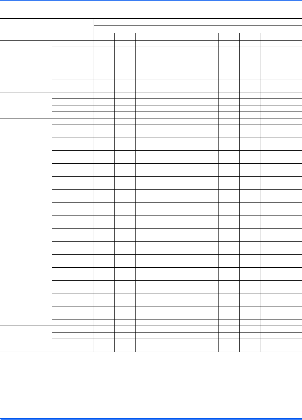
356485-UIM-G-1211
Johnson Controls Unitary Products 25
NOTES:
1. Airflow expressed in standard cubic feet per minute (CFM).
2. Return air is through side opposite motor (left side).
3. Motor voltage at 115 V.
4. Airflow through across motor side (right side) may be slightly less than the data shown above.
Table 14: Blower Performance CFM - Any Position (without filter) - Left Side Return
Models Speed
Left Side Airflow Data (SCFM)
Ext. Static Pressure (in. H2O)
0.1 0.2 0.3 0.4 0.5 0.6 0.7 0.8 0.9 1.0
040A08
High 994 971 942 899 829 725 419 120 NA NA
Medium High 824 804 777 739 675 489 350 361 NA NA
Medium Low 757 733 694 659 575 444 399 NA NA NA
Low 707 684 641 604 495 397 282 NA NA NA
060A10
High 1371 1323 1251 1169 1086 971 843 521 NA NA
Medium High 1249 1207 1158 1098 1018 921 669 503 NA NA
Medium Low 1059 1026 997 949 889 793 582 420 NA NA
Low 854 836 809 775 717 576 464 216 NA NA
060A12
High 1406 1401 1394 1379 1338 1304 1261 1202 1135 1040
Medium High 1129 1126 1107 1094 1076 1047 1010 966 921 843
Medium Low 970 947 933 916 890 863 827 789 741 668
Low 834 809 797 768 740 710 677 634 586 534
080B12
High 1274 1285 1255 1239 1207 1158 1111 1049 979 830
Medium High 975 974 968 960 948 923 879 823 756 672
Medium Low 777 771 772 762 752 734 695 651 604 529
Low 647 634 623 610 602 588 552 506 457 381
080C16
High 1825 1781 1746 1695 1641 1587 1521 1429 1330 1184
Medium High 1516 1493 1482 1464 1442 1411 1343 1275 1192 1035
Medium 1294 1297 1271 1238 1187 1120 1083 1028 979 851
Low 1126 1115 1095 1049 1027 996 957 929 840 742
080C22
High 2972 2863 2769 2671 2571 2465 2352 2227 2095 1950
Medium High 2173 2146 2103 2082 2036 1966 1904 1827 1738 1621
Medium Low 1670 1667 1647 1618 1585 1549 1492 1408 1350 1238
Low 1371 1339 1317 1284 1259 1199 1147 1085 1024 928
100B12
High 1258 1278 1283 1259 1240 1204 1149 1073 1015 897
Medium High 986 995 1011 1003 962 935 913 861 808 738
Medium Low 793 786 786 783 780 750 733 702 627 567
Low 667 653 640 629 604 583 558 519 469 427
100C16
High 2009 1994 1933 1893 1836 1763 1691 1606 1508 1389
Medium High 1523 1506 1521 1490 1466 1435 1393 1326 1241 1119
Medium Low 1230 1249 1245 1230 1218 1195 1161 1120 1039 949
Low 1126 1115 1095 1049 1027 996 957 929 840 742
100C20
High 2964 2886 2794 2707 2623 2522 2415 2281 2149 2012
Medium High 2192 2178 2150 2109 2098 2007 1956 1888 1795 1671
Medium Low 1699 1695 1706 1632 1612 1568 1519 1460 1392 1293
Low 1361 1356 1337 1304 1267 1243 1191 1149 1077 994
120C16
High 1789 1774 1738 1702 1665 1608 1514 1431 1343 1205
Medium High 1451 1445 1431 1413 1394 1362 1312 1235 1149 1037
Medium 1202 1210 1266 1252 1226 1191 1082 1028 950 852
Low 1063 1050 1033 1010 1007 982 941 889 845 778
120C20
High 2828 2768 2699 2612 2524 2423 2308 2219 2118 1982
Medium High 2085 2073 2042 2029 1967 1896 1893 1816 1717 1635
Medium Low 1620 1631 1636 1593 1567 1557 1520 1476 1407 1263
Low 1322 1311 1302 1271 1241 1201 1162 1101 1042 979
130D20
High 2958 2862 2758 2662 2553 2447 2328 2203 2056 1893
Medium High 2191 2182 2157 2092 2085 1997 1932 1844 1741 1608
Medium Low 1737 1738 1713 1691 1675 1590 1531 1467 1389 1276
Low 1404 1394 1380 1355 1327 1276 1220 1163 1095 1013
356485-UIM-G-1211
26 Johnson Controls Unitary Products
SECTION IX: SAFETY CONTROLS
CONTROL CIRCUIT FUSE
A 3-amp fuse is provided on the control circuit board to protect the 24-
volt transformer from overload caused by control circuit wiring errors.
This is an ATO 3, automotive type fuse and is located on the control
board.
BLOWER DOOR SAFETY SWITCH
This unit is equipped with an electrical interlock switch mounted in the
burner compartment. This switch interrupts all power at the unit when
the panel covering the blower compartment is removed.
Electrical supply to this unit is dependent upon the panel that covers the
blower compartment being in place and properly positioned.
ROLLOUT SWITCH CONTROLS
These controls are mounted on the burner assembly. If the temperature
in the area surrounding the burner exceeds its set point, the gas valve
is de-energized. The operation of this control indicates a malfunction in
the combustion air blower, heat exchanger or a blocked vent pipe con-
nection. Corrective action is required. These are manual reset controls
that must be reset before operation can continue.
PRESSURE SWITCHES
This furnace is supplied with a pressure switch, which monitors the flow
through the combustion air/vent piping system. This switch de-ener-
gizes the gas valve if any of the following conditions are present.
1. Blockage of vent piping or terminal.
2. Failure of combustion air blower motor.
LIMIT CONTROLS
There is a high temperature limit control located on the furnace vesti-
bule panel near the gas valve. This is an automatic reset control that
provides over temperature protection due to reduced airflow. This may
be caused by:
1. A dirty filter.
2. If the indoor fan motor should fail.
3. Too many supply or return registers closed or blocked off.
The control module will lockout if the limit trips 5 consecutive times. If
this occurs, control will reset & try ignition again after 1 hour.
SEQUENCE OF OPERATION
The following describes the sequence of operation of the furnace. Refer
to Owners Manual for component location.
Continuous Blower
Cooling/heating thermostats have a fan switch that has an ON and
AUTO position. In the ON position the thermostat circuit is completed
between terminals R and G. The motor will operate continuously on the
speed tap wire that is connected to the “HI COOL” cooling terminal on
the control board. To obtain a constant air circulation at lower flow rate,
change the high-speed wire to either the medium speed wire or the low
speed wire.
Intermittent Blower - Cooling
Cooling/heating thermostats have a fan switch that has an ON and
AUTO position. In the AUTO position the thermostat circuit is completed
between terminals R and G when there is a call for cooling. The motor
will operate on the speed tap wire that is connected to the “HI COOL”
cooling terminal on the control board. The fan off setting is fixed at 60
seconds to improve cooling efficiency.
Heating Cycle
When the thermostat switch is set on HEAT and the fan is set on AUTO,
and there is a call for heat, a circuit is completed between terminals R
and W of the thermostat. When the proper amount of combustion air is
being provided, the pressure switch will close, the ignition control pro-
vides a 17-second ignitor warm-up period, the gas valve then opens,
the gas starts to flow, ignition occurs and the flame sensor begins its
sensing function. The blower motor will energize 30 seconds after the
gas valve opens, if a flame is detected. Normal furnace operation will
continue until the thermostat circuit between R and W is opened, which
causes the ignition system and gas valve to de-energize and the burner
flames to be extinguished. The vent motor will operate for 15 seconds
and the blower motor will operate for the amount of time set by the fan-
off delay jumper located on the control board. See Figure 27. The heat-
ing cycle is now complete, and ready for the start of the next heating
cycle.
If the flame is not detected within 7 seconds of the gas valve opening,
the gas valve is shut off and a retry operation begins. Also, if the flame
is lost for 2 seconds during the 10-second stabilization period, the gas
valve is shut off and a retry operation begins. During a retry operation,
the vent motor starts a 15 second inter-purge and the ignitor warm-up
time is extended to 27 seconds. If the flame is established for more than
10 seconds after ignition during a retry, the control will clear the ignition
attempt (retry) counter. If three retries occur during a call for heat, the
furnace will shut down for one hour. If at the end of the one hour shut
down there is a call for heat, the furnace will initiate a normal start cycle.
If the problem has not been corrected the furnace will again lockout
after three retries.
A momentary loss of gas supply, flame blowout, or a faulty flame probe
circuit will result in a disruption in the flame and be sensed within 1.0
seconds. The gas valve will de-energize and the control will begin a
recycle operation. A normal ignition sequence will begin after a 15 sec-
ond inter-purge. If during the five recycles the gas supply does not
return, or the fault condition is not corrected the ignition control will lock-
out for 60 minutes.
During burner operation, a momentary loss of power for 50 milliseconds
or longer will de-energize the gas valve. When the power is restored,
the gas valve will remain de-energized and the ignition sequence will
immediately restart.
Hot Surface Ignition System
TROUBLESHOOTING
The following visual checks should be made before troubleshooting:
1. Check to see that the power to the furnace and the ignition control
module is ON.
2. The manual shut-off valves in the gas line to the furnace must be
open.
3. Make sure all wiring connections are secure.
4. Review the sequence of operation. Start the system by setting the
thermostat above the room temperature. Observe the system’s
response. Then use the troubleshooting section in this manual to
check the system’s operation.
Main power to the unit must still be interrupted at the main power
disconnect switch before any service or repair work is to be done to
the unit. Do not rely upon the interlock switch as a main power dis-
connect.
Blower and burner must never be operated without the blower
panel in place.
HOT SURFACE IGNITION SYSTEM
Do not attempt to light this furnace by hand (with a match or any
other means). There may be a potential shock hazard from the
components of the hot surface ignition system. The furnace can
only be lit automatically by its hot surface ignition system.
Never bypass any safety control to allow furnace operation. To do
so will allow furnace to operate under potentially hazardous condi-
tions.
Do not try to repair controls. Replace defective controls with UPG
Source 1 Parts.
Never adjust pressure switch to allow furnace operation.

356485-UIM-G-1211
Johnson Controls Unitary Products 27
FURNACE CONTROL DIAGNOSTICS
The furnace has built-in, self-diagnostic capability. A blinking LED light
on the control board can flash red, green or amber to indicate various
conditions. The control continuously monitors its own operation and the
operation of the system. If a failure occurs, the LED light will indicate
the failure code.
The SLOW flash speed is two seconds on and two seconds off.
The other flash codes listed below have the following timing: LED light
will turn on for 1/3 second and off for 1/3 second. This pattern will be
repeated the number of times equal to the code. There will be a two-
second pause between codes. For example, the six red flash code will
flash the LED light on and off six times, then will be off for two seconds.
This pattern will repeat as long as the fault condition remains. The con-
tinuous flash codes listed below will flash the LED light on and off con-
tinuously, with no breaks or longer pauses.
SLOW GREEN FLASH: Normal operation, no thermostat calls.
SLOW AMBER FLASH: Normal operation with call for heat.
LED STEADY OFF – If the LED light does not flash at all, check for
power to the board and check for a blown fuse on the board. If the
board is properly powered and the fuse is not blown, the control board
may need to be replaced.
STEADY ON ANY COLOR: Control failure. Turn power to the furnace
off and back on. If the fault code returns, the control board must be
replaced. The control board is not field-repairable.
CONTINUOUS GREEN FLASH: Twinning error, incorrect 24V phasing
or no power to twinned unit. Check twinning wiring. Confirm that both
twinned units have power.
CONTINUOUS AMBER FLASH: Flame sense current is below 1.5
microamps. Check and clean flame sensor. Check for proper gas flow.
Verify that current is greater than 1.5 microamps at flame current test
pad.
1 RED FLASH: This indicates that flame was sensed when there was
not a call for heat. The control will turn on both the inducer motor and
supply air blower. Check for a leaking or slow-closing gas valve.
2 RED FLASHES: This indicates that the pressure switch is closed
when it should be open. The control confirms that the pressure switch
contacts are open at the beginning of each heat cycle and will not let
the ignition sequence continue if the pressure switch contacts are
closed when they should be open. Check for a faulty pressure switch or
miswiring.
3 RED FLASHES: This indicates the pressure switch contacts are open
when they should be closed. Check for faulty inducer, blocked vent
pipe, broken pressure switch hose, disconnected pressure switch or
inducer wires or faulty pressure switch.
4 RED FLASHES: This indicates that the main limit switch has opened
its normally closed contacts. The control will operate the supply air
blower and inducer while the open limit condition exists. Check for a
dirty filter, improperly sized duct system, incorrect blower speed setting,
incorrect firing rate, loose limit switch wiring or faulty blower motor.
If the limit switch has not closed within five minutes, the control will
assume that the blower is not functioning, will start a hard lockout and
will begin to flash the 11 Red Flashes error code. Power will have to be
cycled off and on to reset the control after the problem has been cor-
rected. See “11Red Flashes” description below.
If the main limit switch opens five times within a single call for heat, the
control will also indicate 4 Red Flashes and will enter a one-hour soft
lockout.
5 RED FLASHES: This fault is indicated if the normally closed rollout
switch opens. The rollout control is manually reset. Check for proper
combustion air, proper inducer operation, and primary heat exchanger
failure or burner problem. The control will enter a hard lockout and
power will have to be cycled off and on to reset the control after the
problem has been corrected.
6 RED FLASHES: This indicates that while the unit was operating, the
pressure switch opened four times during the call for heat. Check for
faulty inducer, blocked vent pipe or faulty pressure switch. The furnace
will lock out for one hour and then restart.
7 RED FLASHES: This fault code indicates that the flame could not be
established during three trials for ignition. Check that the gas valve
switch is in the ON position. Check for low or no gas pressure, faulty
gas valve, dirty or faulty flame sensor, faulty hot surface ignitor, loose
wires or a burner problem. The furnace will lock out for one hour and
then restart.
8 RED FLASHES: This fault is indicated if the flame is lost five times
(four recycles) during the heating cycle. Check for low gas pressure,
dirty or faulty flame sensor or faulty gas valve. The furnace will lock out
for one hour and then restart.
9 RED FLASHES: Indicates reversed line voltage polarity, grounding
problem or reversed low voltage transformer wires. Both heating and
cooling operations will be affected. Check polarity at furnace and
branch. Check furnace grounding. Check that flame probe is not
shorted to chassis. The furnace will not start the ignition sequence until
this problem is corrected.
10 RED FLASHES: Gas valve energized with no call for heat. The main
blower and inducer blower will run and no ignition sequence will be
started as long as this condition exists. Check gas valve and gas valve
wiring.
11 RED FLASHES: This indicates that the main limit switch has opened
its normally-closed contacts and has remained open for more than five
minutes. This condition is usually caused by a failed blower motor or
blower wheel. The control will enter a hard lockout and power will have
to be cycled off and on to reset the control after the problem has been
corrected.
4 AMBER FLASHES: The control is receiving a “Y” signal from the
thermostat without a “G” signal. The furnace will operate normally in
both heating and cooling, but this fault code will be displayed in order to
alert the user that there is a wiring problem. Verify that the “G” wire from
the thermostat is connected properly.
SOFT LOCKOUT: This control includes a soft lockout that will reset
automatically after one hour. This provides protection to an unoccupied
structure if a temporary condition exists causing a furnace malfunction.
An example of this is a temporary interruption in gas supply that would
prevent the furnace from lighting. The control will keep trying to light
each hour and will resume normal operation if the gas supply is
restored.
HARD LOCKOUT: Some fault conditions result in a hard lockout, which
requires power to the control to be turned off and then back on to reset
the control. The control will not automatically restart.
IGNITION CONTROL FLAME SENSE LEVELS
Normal flame sense current is approximately
3.7 microamps DC (µa)
Low flame signal warning starts at 1.5 microamps.
Low flame signal control lockout point is
0.1 microamps DC (µa)
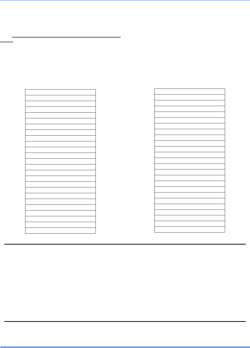
356485-UIM-G-1211
28 Johnson Controls Unitary Products
DIAGNOSTIC FAULT CODE STORAGE AND
RETRIEVAL
The control in this furnace is equipped with memory that will store up to
five error codes to allow a service technician to diagnose problems
more easily. This memory will be retained even if power to the furnace
is lost. This feature should only be used by a qualified service tech-
nician.
If more than five error codes have occurred since the last reset, only the
five most recent will be retained. The furnace control board has a but-
ton, labeled "LAST ERROR" that is used to retrieve error codes. This
function will only work if there are no active thermostat signals. So any
call for heating, cooling or continuous fan must be terminated before
attempting to retrieve error codes.
To retrieve the error codes, push the LAST ERROR button. The LED on
the control will then flash the error codes that are in memory, starting
with the most recent. There will be a two-second pause between each
flash code. After the error codes have all been displayed, the LED will
resume the normal slow green flash after a five second pause. To
repeat the series of error codes, push the button again.
If there are no error codes in memory, the LED will flash two green
flashes. To clear the memory, push the LAST ERROR button and hold it
for more than five seconds. The LED will flash three green flashes when
the memory has been cleared, then will resume the normal slow green
flash after a five-second pause.
SECTION X: REPLACEMENT PARTS LIST
DESCRIPTION
MOTOR
MOTOR, DIRECT DRIVE BLOWER
BLOWER, COMBUSTION
ELECTRICAL
CAPACITOR, RUN
SWITCH, LIMIT
CONTROL, FURNACE
IGNITER
SENSOR, FLAME
SWITCH, PRESSURE
SWITCH, DOOR
TRANSFORMER
VALVE, GAS
CONTROL, TEMPERATURE
AIR MOVING
HOUSING, BLOWER
HOUSING, BLOWER w/WHEEL
WHEEL, BLOWER
FABRICATED PARTS
BAFFLE, FLUE
BURNER, MAIN GAS
BRACKET, IGNITER
SHELF, BLOWER
RAIL, BLOWER (2 Req’d)
FABRICATED PARTS
BRACKET, BLOWER TRACK (2 Req’d)
HEAT EXCHANGER ASS’Y
MANIFOLD, GAS
PAN, BOTTOM
PANEL, TOP
PANEL, DOOR (2 Req’d)
VENT PAN, COMBUSTION (w/Gasket)
PANEL, BLOCKOFF
LO-NOX SCREEN (L-Models Only)
MISCELLANEOUS
ORIFICE, BURNER (Natural #45)
SIGHT GLASS, OVAL (2 Req’d)
GASKET, FOAM (Door) (1.5 ft req’d)
GASKET, INTAKE PAN
PLUG, VENT HOLE
BRACKET, DOOR
WIRING HARNESS
FERRULE (3 Req’d)
GROMMET (3 Req’d)
MOTOR MOUNT
TUBING, SILICON
DIAGRAM, WIRING
KNOB, QUARTER TURN (4 Req’d)
DESCRIPTION (Continued)
REPLACEMENT PART CONTACT INFORMATION
This is a generic parts list. To request a complete parts list, refer to the contact information below:
• Visit our website at www.source1parts.com for the following information:
1. Search for a part or browse the catalog.
2. Find a dealer or distributor.
3. Customer Service contact information.
a. Click on the “Brand Links” button
b. Click on the “Customer Service” button
• You can contact us by mail. Just send a written request to:
Johnson Controls Unitary Products
Consumer Relations
5005 York Drive
Norman, OK 73069
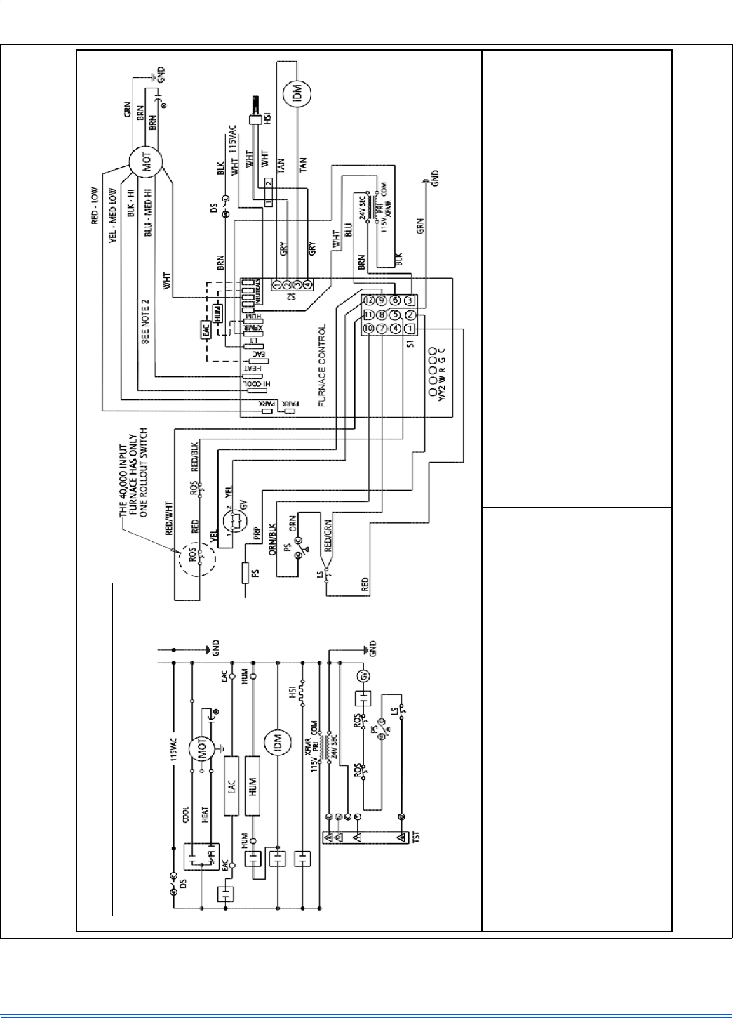
356485-UIM-G-1211
Johnson Controls Unitary Products 29
SECTION XI: WIRING DIAGRAM
FIGURE 28: Wiring Diagram
LEGEND
DSDoorswitch MOTCirculatingmotor LSLimitswitch
ROSRolloutswitch IDMInducermotor HUMHumidifier
PSPressureswitch FSFlamesensor CAPCapacitor
TSTWallthermostat GVGasvalve XFMRTransformer
HSIHotsurfaceigniter EACElectronicaircleaner
1.Ifanyoftheoriginalwireassuppliedwiththefurnacemustbereplaced,itmust
bereplacedwithwiringmaterialhavingatemperaturerangofatleast221F
(105C).
2.Blowermotorspeedconnectionsshownaretypical,butmayvarybymodeland
application.
LEGENDE
DSCommutateurdeporte MOTMoteursoufflerie TSTThermostat
ROSCommutateurderoulement IDMDinductmoteur FSCapteurdeflame
PSCommutateurdepression EACFiltreélectrique CAPCapaciteur
LSCommutateurdelimite GVSoupapedegaz HUMHumidificateur
XFMRTransformeur HSIIgnitiondesurfacechaud
1.Sil'undesfilsd'originefourniaveccefourdoitêtreremplacé,ildoitêtreremplacéavec
lefilayantundegrédetempératured'aumoins221F(105C).
2.Lesconnexionsàgrandevitessedumoteurduventilateurindiquéssonttypiques,mais
peuventvarierselonlemodèleetparapplication.
WiringDiagram
80%SingleStageFurnace
348817-UWD-D-0810

Subject to change without notice. Published in U.S.A. 356485-UIM-G-1211
Copyright © 2011 by Johnson Controls, Inc. All rights reserved. Supersedes: 356485-UIM-F-0910
Johnson Controls Unitary Products
5005 York Drive
Norman, OK 73069
NOTES
