Johnson Controls Inc Furnace Gg9Smp Users Manual 364861 UIM H 0712
GG9S'MP to the manual 8223ebe2-2a61-4357-add8-bda3a3918e41
2015-02-09
: Johnson-Controls Johnson-Controls-Johnson-Controls-Inc-Furnace-Gg9Smp-Users-Manual-566968 johnson-controls-johnson-controls-inc-furnace-gg9smp-users-manual-566968 johnson-controls pdf
Open the PDF directly: View PDF ![]() .
.
Page Count: 40

364861-UIM-H-0712
RESIDENTIAL GAS FURNACE
MODELS: TG9S*MP, GG9S*MP
(95.5% AFUE Single Stage Multi-position)
INSTALLATION MANUAL
LIST OF SECTIONS
SAFETY . . . . . . . . . . . . . . . . . . . . . . . . . . . . . . . . . . . . . . . . . . . 2
DUCTWORK . . . . . . . . . . . . . . . . . . . . . . . . . . . . . . . . . . . . . . . . 5
FILTERS . . . . . . . . . . . . . . . . . . . . . . . . . . . . . . . . . . . . . . . . . . . 9
GAS PIPING . . . . . . . . . . . . . . . . . . . . . . . . . . . . . . . . . . . . . . . 10
ELECTRICAL POWER . . . . . . . . . . . . . . . . . . . . . . . . . . . . . . . 11
TWINNING AND STAGING . . . . . . . . . . . . . . . . . . . . . . . . . . . 15
CONDENSATE PIPING AND FURNACE
VENTING CONFIGURATION . . . . . . . . . . . . . . . . . . . . . . . . . . 16
COMBUSTION AIR and VENT SYSTEM . . . . . . . . . . . . . . . . . 22
START-UP AND ADJUSTMENTS . . . . . . . . . . . . . . . . . . . . . . 29
SAFETY CONTROLS . . . . . . . . . . . . . . . . . . . . . . . . . . . . . . . . 36
NORMAL OPERATION AND DIAGNOSTICS . . . . . . . . . . . . . 36
REPLACEMENT PARTS LIST . . . . . . . . . . . . . . . . . . . . . . . . . 38
REPLACEMENT PART CONTACT INFORMATION . . . . . . . . 38
WIRING DIAGRAM . . . . . . . . . . . . . . . . . . . . . . . . . . . . . . . . . . 39
LIST OF FIGURES
Duct Attachment . . . . . . . . . . . . . . . . . . . . . . . . . . . . . . . . . . . . . 5
Vertical Applications . . . . . . . . . . . . . . . . . . . . . . . . . . . . . . . . . . 6
Coil Flange . . . . . . . . . . . . . . . . . . . . . . . . . . . . . . . . . . . . . . . . . 6
Horizontal Right Application . . . . . . . . . . . . . . . . . . . . . . . . . . . . 6
Horizontal Left Application . . . . . . . . . . . . . . . . . . . . . . . . . . . . . . 6
PC Series Upflow Coil Installation . . . . . . . . . . . . . . . . . . . . . . . . 7
Horizontal Left or Right application (Right Shown) . . . . . . . . . . . 7
Combustible Floor Base Accessory . . . . . . . . . . . . . . . . . . . . . . . 7
Horizontal Application . . . . . . . . . . . . . . . . . . . . . . . . . . . . . . . . . 7
Typical Attic Installation . . . . . . . . . . . . . . . . . . . . . . . . . . . . . . . . 8
Typical Suspended Furnace / Crawl Space Installation . . . . . . . 8
Downflow Venting . . . . . . . . . . . . . . . . . . . . . . . . . . . . . . . . . . . . 8
Dimensions . . . . . . . . . . . . . . . . . . . . . . . . . . . . . . . . . . . . . . . . . 9
Side Return Cutout Markings . . . . . . . . . . . . . . . . . . . . . . . . . . 10
Gas Valve . . . . . . . . . . . . . . . . . . . . . . . . . . . . . . . . . . . . . . . . . 10
Gas Piping . . . . . . . . . . . . . . . . . . . . . . . . . . . . . . . . . . . . . . . . . 10
Electrical Wiring . . . . . . . . . . . . . . . . . . . . . . . . . . . . . . . . . . . . . 12
Thermostat Chart - Single Stage AC
with Single Stage PSC Furnaces . . . . . . . . . . . . . . . . . . . . . . . 13
Thermostat Chart - Single Stage HP
with Single Stage PSC Furnaces . . . . . . . . . . . . . . . . . . . . . . . 14
Typical Twinned Furnace Application . . . . . . . . . . . . . . . . . . . . 15
Twinning Wiring Diagram . . . . . . . . . . . . . . . . . . . . . . . . . . . . . 16
Staging Wiring Diagram . . . . . . . . . . . . . . . . . . . . . . . . . . . . . . . 16
Typical. Condensate drain, vertical installation . . . . . . . . . . . . . 17
Typical. Combustion Pipe Drain Tee . . . . . . . . . . . . . . . . . . . . . 17
Upflow Configuration . . . . . . . . . . . . . . . . . . . . . . . . . . . . . . . . . 18
Downflow Configuration . . . . . . . . . . . . . . . . . . . . . . . . . . . . . . 19
Horizontal Left Configuration . . . . . . . . . . . . . . . . . . . . . . . . . . . 20
Horizontal Right Configuration . . . . . . . . . . . . . . . . . . . . . . . . . 21
Dimensions . . . . . . . . . . . . . . . . . . . . . . . . . . . . . . . . . . . . . . . . 23
Home Layout . . . . . . . . . . . . . . . . . . . . . . . . . . . . . . . . . . . . . . . 24
Termination Configuration - 1 Pipe . . . . . . . . . . . . . . . . . . . . . . 25
Termination Configuration - 2 Pipe . . . . . . . . . . . . . . . . . . . . . . 25
Termination Configuration - 2 Pipe Basement . . . . . . . . . . . . . 25
Double Horizontal Combustion
Air Intake and Vent Termination . . . . . . . . . . . . . . . . . . . . . . . . 26
Double Vertical Combustion
Air Intake and Vent Termination . . . . . . . . . . . . . . . . . . . . . . . . 26
Downward Venting . . . . . . . . . . . . . . . . . . . . . . . . . . . . . . . . . . 26
Direct Vent Air Intake Connection and Vent Connection . . . . . . 26
Combustion Airflow Path Through The Furnace Casing . . . . . . 27
Outside and Ambient Combustion Air . . . . . . . . . . . . . . . . . . . . 28
Attic and Crawl Space Combustion Air Termination . . . . . . . . . 28
Gas Valve . . . . . . . . . . . . . . . . . . . . . . . . . . . . . . . . . . . . . . . . . 32
Reading Gas Pressure . . . . . . . . . . . . . . . . . . . . . . . . . . . . . . . 33
Furnace Control Board . . . . . . . . . . . . . . . . . . . . . . . . . . . . . . . 33
Wiring Diagram . . . . . . . . . . . . . . . . . . . . . . . . . . . . . . . . . . . . . 39
LIST OF TABLES
Unit Clearances to Combustibles . . . . . . . . . . . . . . . . . . . . . . . . 4
Coil Projection Dimensions - PC Series Coils . . . . . . . . . . . . . . . 7
Cabinet and Duct Dimensions . . . . . . . . . . . . . . . . . . . . . . . . . . . 9
Recommended Filter Sizes (High Velocity 600 FPM) . . . . . . . . . 9
Nominal Manifold Pressure - High Fire . . . . . . . . . . . . . . . . . . . 11
Ratings & Physical / Electrical Data . . . . . . . . . . . . . . . . . . . . . 12
Maximum Equivalent Pipe Length . . . . . . . . . . . . . . . . . . . . . . . 22
Elbow Dimensions . . . . . . . . . . . . . . . . . . . . . . . . . . . . . . . . . . . 23
Equivalent Length of Fittings . . . . . . . . . . . . . . . . . . . . . . . . . . . 23
Combustion Air Intake and Vent Connection
Size at Furnace (All Models) . . . . . . . . . . . . . . . . . . . . . . . . . . . 23
Estimated Free Area . . . . . . . . . . . . . . . . . . . . . . . . . . . . . . . . . 27
Unconfined Space Minimum Area . . . . . . . . . . . . . . . . . . . . . . . 27
Free Area . . . . . . . . . . . . . . . . . . . . . . . . . . . . . . . . . . . . . . . . . 27
Gas Rate (CU FT/HR) at Full Input . . . . . . . . . . . . . . . . . . . . . . 31
Inlet Gas Pressure Range . . . . . . . . . . . . . . . . . . . . . . . . . . . . . 32
Nominal Manifold Pressure . . . . . . . . . . . . . . . . . . . . . . . . . . . . 32
Blower Performance CFM - Any Position
(without filter) - Bottom Return . . . . . . . . . . . . . . . . . . . . . . . . . 34
Blower Performance CFM - Any Position
(without filter) - Left Side Return . . . . . . . . . . . . . . . . . . . . . . . . 35
364861-UIM-H-0712
2Johnson Controls Unitary Products
These high efficiency, compact units employ induced combustion, reli-
able hot surface ignition and high heat transfer aluminized tubular heat
exchangers. The units are factory shipped for installation in upflow or
horizontal applications and may be converted for downflow applica-
tions.
These furnaces are designed for residential installation in a basement,
closet, alcove, attic, recreation room or garage and are also ideal for
commercial applications. All units are factory assembled, wired and
tested to assure safe dependable and economical installation and oper-
ation.
These units are Category IV listed and may not be common vented with
another gas appliance as allowed by the National Fuel Gas Code.
SECTION I: SAFETY
This is a safety alert symbol. When you see this symbol on
labels or in manuals, be alert to the potential for personal
injury.
Understand and pay particular attention to the signal words DANGER,
WARNING, or CAUTION.
DANGER indicates an imminently hazardous situation, which, if not
avoided, will result in death or serious injury.
WARNING indicates a potentially hazardous situation, which, if not
avoided, could result in death or serious injury.
CAUTION indicates a potentially hazardous situation, which, if not
avoided may result in minor or moderate injury. It is also used to
alert against unsafe practices and hazards involving only property dam-
age.
SPECIFIC SAFETY RULES AND PRECAUTIONS
1. Only Natural gas or Propane (LP) gas are approved for use with
this furnace.
2. Install this furnace only in a location and position as specified in
these instructions.
3. A gas-fired furnace for installation in a residential garage must be
installed as specified in these instructions.
4. Provide adequate combustion and ventilation air to the furnace
space as specified in these instructions.
5. Combustion products must be discharged outdoors. Connect this
furnace to an approved vent system only, as specified in "COM-
BUSTION AIR and VENT SYSTEM" of these instructions.
6. Test for gas leaks as specified in these instructions.
7. Always install the furnace to operate within the furnace’s intended
temperature rise range. Only connect the furnace to a duct system
which has an external static pressure within the allowable range, as
specified on the furnace rating plate.
8. When a furnace is installed so that supply ducts carry air circulated
by the furnace to areas outside the space containing the furnace,
the return air shall also be handled by duct(s) sealed to the furnace
casing and terminating outside the space containing the furnace.
9. It is permitted to use the furnace for heating of buildings or struc-
tures under construction where the application and use must com-
ply with all manufacturer’s installation instructions including:
• Proper vent installation;
• Furnace operating under thermostatic control;
• Return air duct sealed to the furnace;
• Air filters in place;
• Set furnace input rate and temperature rise per rating plate mark-
ing;
• Means for providing outdoor air required for combustion;
• Return air temperature maintained between 55ºF (13ºC) and
80ºF (27ºC);
•The air filter must be replaced upon substantial completion of
the construction process;
• Clean furnace, duct work and components upon substantial com-
pletion of the construction process, and verify furnace-operating
conditions including ignition, input rate, temperature rise and
venting, according to the manufacturer’s instructions.
10. When installed in a non-HUD-Approved Modular Home or building
constructed on-site, combustion air shall not be supplied from occu-
pied spaces.
11. The size of the unit should be based on an acceptable heat loss
calculation for the structure. ACCA, Manual J or other approved
methods may be used.
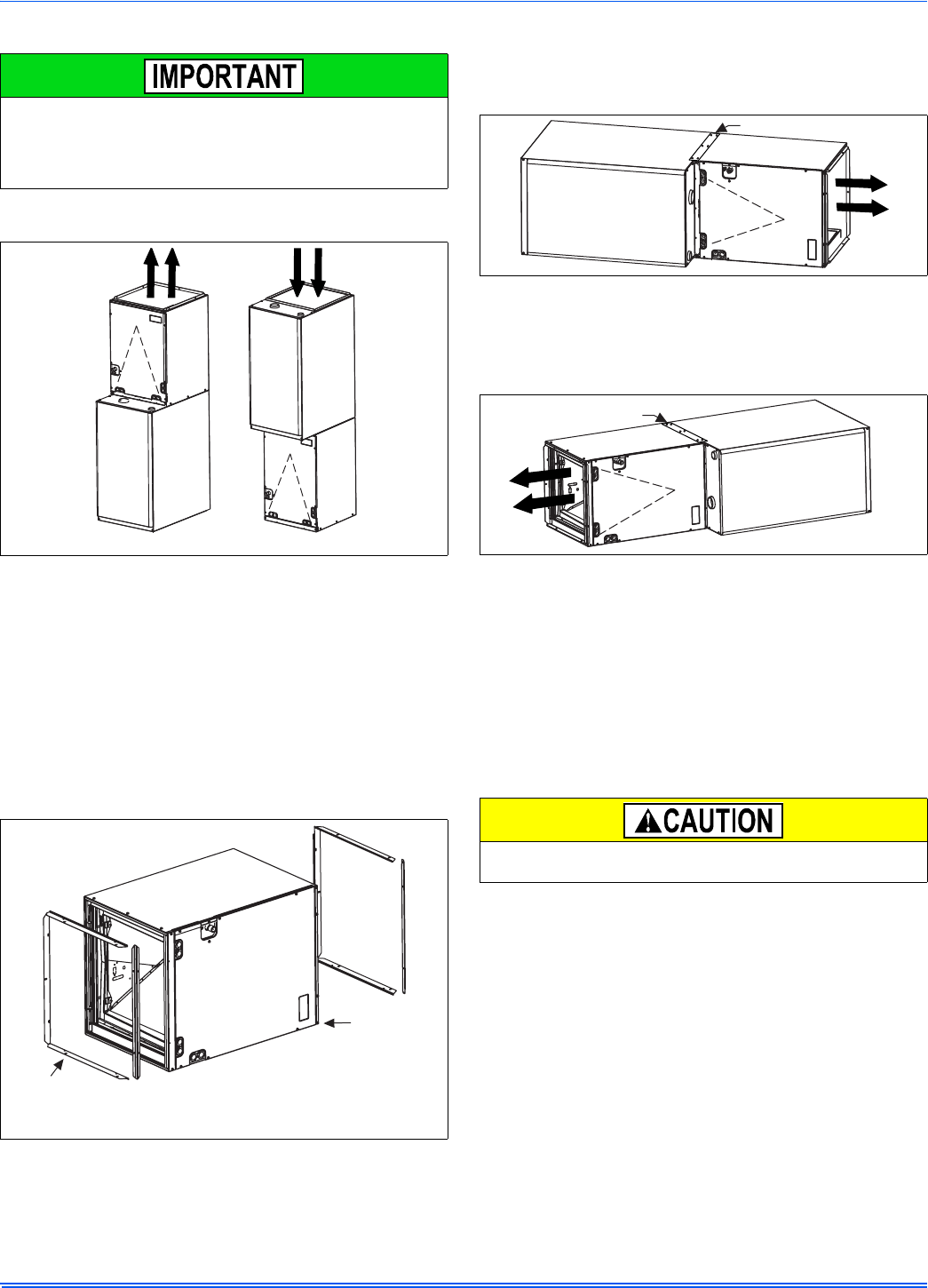
12. When moving or handling this furnace prior to installation, always
leave the doors on the furnace to provide support and to prevent
damage or warping of the cabinet. When lifting the furnace by the
cabinet, support the ends of the furnace rather than lifting by the
cabinet flanges at the return air openings (bottom or sides) or sup-
ply air opening.
13. When lifting the furnace, it is acceptable to use the primary heat
exchanger tubes as a lifting point provided that the tubes are lifted
at the front of the heat exchangers where attached to the vestibule
panel. Do not use the top return bend of the heat exchangers as lift-
ing points as the tubes may shift out of position or their location
brackets/baffles.
SAFETY REQUIREMENTS
• Refer to the unit rating plate for the furnace model number, and
then see the dimensions page of this instruction for return air ple-
num dimensions in Figure 13. The plenum must be installed
according to the instructions.
• Provide clearances from combustible materials as listed under
Clearances to Combustibles.
• Provide clearances for servicing ensuring that service access is
allowed for both the burners and blower.
• These models ARE NOT CSA listed or approved for installation
into a HUD Approved Modular Home or a Manufactured
(Mobile) Home.
• This furnace is not approved for installation in trailers or recre-
ational vehicles.
• Furnaces for installation on combustible flooring shall not be
installed directly on carpeting, tile or other combustible material
other than wood flooring.
Improper installation may create a condition where the operation of
the product could cause personal injury or property damage.
Improper installation, adjustment, alteration, service or maintenance
can cause injury or property damage. Failure to carefully read and
follow all instructions in this manual can result in furnace mal-
function, death, personal injury and/or property damage. Only a
qualified contractor, installer or service agency should install this
product.
FIRE OR EXPLOSION HAZARD
Failure to follow the safety warnings exactly could result in serious
injury, death or property damage.
Never test for gas leaks with an open flame. Use a commercially
available soap solution made specifically for detection of leaks to
check all connections. A fire or explosion may result causing property
damage, personal injury or loss of life.
During installation, doors should remain on the furnace when
moving or lifting.
This product must be installed in strict compliance with the installation
instructions and any applicable local, state, and national codes
including, but not limited to building, electrical, and mechanical codes.
364861-UIM-H-0712
Johnson Controls Unitary Products 3
• Check the rating plate and power supply to be sure that the elec-
trical characteristics match. All models use nominal 115 VAC, 1
Phase, 60-Hz power supply. DO NOT CONNECT THIS APPLI-
ANCE TO A 50-Hz POWER SUPPLY OR A VOLTAGE ABOVE
130 VOLTS.
• Furnace shall be installed so the electrical components are pro-
tected from water.
• Installing and servicing heating equipment can be hazardous due
to the electrical components and the gas fired components. Only
trained and qualified personnel should install, repair, or service
gas heating equipment. Untrained service personnel can perform
basic maintenance functions such as cleaning and replacing the
air filters. When working on heating equipment, observe precau-
tions in the manuals and on the labels attached to the unit and
other safety precautions that may apply.
COMBUSTION AIR QUALITY
(LIST OF CONTAMINANTS)
The furnace requires OUTDOOR AIR for combustion when the furnace
is located in any of the following environments.
• Buildings with indoor pools
• Chemical exposure
• Commercial buildings
• Furnaces installed in hobby or craft rooms
• Furnaces installed in laundry rooms
• Furnaces installed near chemical storage areas
• Restricted Environments
The furnace requires OUTDOOR AIR for combustion when the furnace
is located in an area where the furnace is being exposed to the follow-
ing substances and / or chemicals.
• Antistatic fabric softeners for clothes dryers
• Carbon tetrachloride
• Cements and glues
• Chlorine based swimming pool chemicals
• Chlorinated waxes and cleaners
• Cleaning solvents (such as perchloroethylene)
• De-icing salts or chemicals
• Halogen type refrigerants
• Hydrochloric acid
• Masonry acid washing materials
• Permanent wave solutions
• Printing inks, paint removers, varnishes, etc.
• Water softening chemicals
When outdoor air is used for combustion, the combustion air intake duct
system termination must be located external to the building and in an
area where there will be no exposure to the substances listed above.
CODES AND STANDARDS
Follow all national, local codes and standards in addition to this installa-
tion manual. The installation must comply with regulations of the serv-
ing gas supplier, local building, heating, plumbing, and other codes. In
absence of local codes, the installation must comply with the national
codes listed below and all authorities having jurisdiction.
In the United States and Canada, follow all codes and standards for the
following, using the latest edition available:
STEP 1 - Safety
• US: National Fuel Gas Code (NFGC) NFPA 54/ANSI Z223.1 and
the Installation Standards, Warm Air Heating and Air Conditioning
Systems ANSI/NFPA 90B
• CANADA: CAN/CGA-B149.1 National Standard of Canada. Natu-
ral Gas and Propane Installation Codes (NSCNGPIC)
STEP 2 - General Installation
• US: Current edition of the NFGC and NFPA 90B. For copies, con-
tact the
National Fire Protection Association Inc.
Batterymarch Park
Quincy, MA 02269
or for only the NFGC, contact the
American Gas Association,
400 N. Capital, N.W.
Washington DC 20001
or www.NFPA.org
• CANADA: NSCNGPIC. For a copy contact:
Standard Sales, CSA International
178 Rexdale Boulevard
Etobicoke, (Toronto) Ontario Canada M9W 1RS
STEP 3 - Combustion and Ventilation Air
• US: Section 5.3 of the NFGC, air for Combustion and Ventilation
• CANADA: Part 7 of NSCNGPIC, Venting Systems and Air Supply
for Appliances
STEP 4 - Duct Systems
• US and CANADA: Air Conditioning Contractors Association
(ACCA) Manual D, Sheet Metal and Air Conditioning Contractors
Association National Association (SMACNA), or American Soci-
ety of Heating, Refrigeration, and Air Conditioning Engineers
(ASHRAE) 1997 Fundamentals Handbook Chapter 32.
STEP 5 - Acoustical Lining and Fibrous Glass Duct
• US and CANADA: Current edition of SMACNA and NFPA 90B as
tested by UL Standard 181 for Class I Rigid Air Ducts
STEP 6 - Gas Piping and Gas Pipe Pressure Testing
• US: NFGC; chapters 2, 3, 4, & 9 and National Plumbing Codes
• CANADA: NSCNGPIC Part 5
STEP 7 - Electrical Connections
• US: National Electrical Code (NEC) ANSI/NFPA 70
• CANADA: Canadian Electrical Code CSA C22.1
These instructions cover minimum requirements and conform to exist-
ing national standards and safety codes. In some instances these
instructions exceed certain local codes and ordinances, especially
those who have not kept up with changing residential and non-HUD
modular home construction practices. These instructions are required
as a minimum for a safe installation.
The furnace area must not be used as a broom closet or for any other
storage purposes, as a fire hazard may be created. Never store items
such as the following on, near or in contact with the furnace.
1. Spray or aerosol cans, rags, brooms, dust mops, vacuum
cleaners or other cleaning tools.
2. Soap powders, bleaches, waxes or other cleaning com-
pounds; plastic items or containers; gasoline, kerosene, ciga-
rette lighter fluid, dry cleaning fluids or other volatile fluid.
3. Paint thinners and other painting compounds.
4. Paper bags, boxes or other paper products
Never operate the furnace with the blower door removed. To do
so could result in serious personal injury and/or equipment
damage.
364861-UIM-H-0712
4Johnson Controls Unitary Products
INSPECTION
As soon as a unit is received, it should be inspected for possible dam-
age during transit. If damage is evident, the extent of the damage
should be noted on the carrier’s freight bill. A separate request for
inspection by the carrier’s agent should be made in writing. Also, before
installation, the unit should be checked for screws or bolts which may
have loosened in transit. There are no shipping or spacer brackets
which need to be removed from the interior of this unit.
FURNACE LOCATION AND CLEARANCES
The furnace shall be located using the following guidelines:
1. Where a minimum amount of air intake/vent piping and elbows will
be required.
2. As centralized with the air distribution as possible.
3. Where adequate combustion air will be available (particularly when
the appliance is not using outdoor combustion air).
4. Where it will not interfere with proper air circulation in the confined
space.
5. Where the outdoor vent terminal will not be blocked or restricted.
Refer to “VENT CLEARANCES” located in SECTION VII of these
instructions. These minimum clearances must be maintained in the
installation.
6. Where the unit will be installed in a level position with no more than
1/4” (6.4 mm) slope side-to-side and front-to-back to provide proper
condensate drainage.
Installation in freezing temperatures:
1. Furnace shall be installed in an area where ventilation facilities pro-
vide for safe limits of ambient temperature under normal operating
conditions. Ambient temperatures must not fall below 32°F (0°C)
unless the condensate system is protected from freezing.
2. Do not allow return air temperature to be below 55ºF (13°C) for
extended periods. To do so may cause condensation to occur in the
main heat exchanger, leading to premature heat exchanger failure.
3. If this furnace is installed in an unconditioned space and an
extended power failure occurs, there will be potential damage to the
internal components. Following a power failure situation, do not
operate the unit until inspection and repairs are performed.
Clearances for access/service:
Ample clearances should be provided to permit easy access to the unit.
The following minimum clearances are recommended:
1. Twenty-four (24) inches (61 cm) between the front of the furnace
and an adjacent wall or another appliance, when access is required
for servicing and cleaning.
2. Eighteen (18) inches (46 cm) at the side where access is required
for passage to the front when servicing or for inspection or replace-
ment of flue/vent connections.
In all cases, accessibility clearances shall take precedence over clear-
ances for combustible materials where accessibility clearances are
greater.
Installation in a residential garage:
A gas-fired furnace for installation in a residential garage must be
installed so the burner(s) and the ignition source are located not less
than 18” (46 cm) above the floor, and the furnace must be located or
protected to avoid physical damage by vehicles.
* 24" clearance in front and 18" on side recommended for service access.
All furnaces approved for alcove and attic installation.
FOR FURNACES INSTALLED IN THE COMMON-
WEALTH OF MASSACHUSETTS ONLY
For all side wall horizontally vented gas fueled equipment installed in
every dwelling, building or structure used in whole or in part for resi-
dential purposes, including those owned or operated by the Com-
monwealth and where the side wall exhaust vent termination is less
than seven (7) feet above finished grade in the area of the venting,
including but not limited to decks and porches, the following require-
ments shall be satisfied:
1. INSTALLATION OF CARBON MONOXIDE DETECTORS. At
the time of installation of the side wall horizontal vented gas
fueled equipment, the installing plumber or gasfitter shall
observe that a hard wired carbon monoxide detector with an
alarm and battery back-up is installed on the floor level where the
gas equipment is to be installed. In addition, the installing
plumber or gasfitter shall observe that a battery operated or hard
wired carbon monoxide detector with an alarm is installed on
each additional level of the dwelling, building or structure served
by the side wall horizontal vented gas fueled equipment. It shall
be the responsibility of the property owner to secure the services
of qualified licensed professionals for the installation of hard
wired carbon monoxide detectors
a. In the event that the side wall horizontally vented gas
fueled equipment is installed in a crawl space or an attic,
the hard wired carbon monoxide detector with alarm and
battery back-up may be installed on the next adjacent floor
level.
b. In the event that the requirements of this subdivision can
not be met at the time of completion of installation, the
owner shall have a period of thirty (30) days to comply with
the above requirements; provided, however, that during
said thirty (30) day period, a battery operated carbon mon-
oxide detector with an alarm shall be installed.
2. APPROVED CARBON MONOXIDE DETECTORS. Each carbon
monoxide detector as required in accordance with the above pro-
visions shall comply with NFPA 720 and be ANSI/UL 2034 listed
and IAS certified.
3. SIGNAGE. A metal or plastic identification plate shall be perma-
nently mounted to the exterior of the building at a minimum
height of eight (8) feet above grade directly in line with the
exhaust vent terminal for the horizontally vented gas fueled heat-
ing appliance or equipment. The sign shall read, in print size no
less than one-half (1/2) inch in size, "GAS VENT DIRECTLY
BELOW. KEEP CLEAR OF ALL OBSTRUCTIONS".
4. INSPECTION. The state or local gas inspector of the side wall
horizontally vented gas fueled equipment shall not approve the
installation unless, upon inspection, the inspector observes car-
bon monoxide detectors and signage installed in accordance
with the provisions of 248 CMR 5.08(2)(a)1 through 4.
Improper installation in an ambient below 32ºF (0° C) could create a
hazard, resulting in damage, injury or death.
Liquid anti-freeze will cause damage to internal plastic parts of this
furnace. DO NOT attempt to winterize the furnace using liquid
anti-freeze.
Table 1: Unit Clearances to Combustibles
Application Upflow Downflow Horizontal
Top 1" 0" 0"
Vent 0" 0" 0"
Rear 0" 0" 0"
Side 0" 0" 1"
Front* 0" 0" 0"
Floor Combustible Combustible1
1. For combustible floors only when used with special sub-base.
Combustible
Closet Yes Yes Yes
Line Contact No No Yes
364861-UIM-H-0712
Johnson Controls Unitary Products 5
SECTION II: DUCTWORK
DUCTWORK GENERAL INFORMATION
The duct system’s design and installation must:
1. Handle an air volume appropriate for the served space and within
the operating parameters of the furnace specifications.
2. Be installed in accordance of National Fire Protection Association
as outlined in NFPA standard 90B (latest editions) or applicable
national, provincial, state, and local fire and safety codes.
3. Create a closed duct system. For residential and non-HUD Modular
Home installations, when a furnace is installed so that the supply
ducts carry air circulated by the furnace to areas outside the space
containing the furnace, the return air shall also be handled by a
duct(s) sealed to the furnace casing and terminating outside the
space containing the furnace.
4. Complete a path for heated or cooled air to circulate through the air
conditioning and heating equipment and to and from the condi-
tioned space.
When the furnace is used with a cooling coil, the coil must be installed
parallel with, or in the supply air side of the furnace to avoid condensa-
tion in the primary heat exchanger. When a parallel flow arrangement is
used, dampers or other means used to control airflow must be ade-
quate to prevent chilled air from entering the furnace. If manually oper-
ated, the damper must be equipped with means to prevent the furnace
or the air conditioner from operating unless the damper is in full heat or
cool position.
When replacing an existing furnace, if the existing plenum is not the
same size as the new furnace then the existing plenum must be
removed and a new plenum installed that is the proper size for the new
furnace. If the plenum is shorter than 12” (30.5 cm) the turbulent air flow
may cause the limit controls not to operate as designed, or the limit con-
trols may not operate at all.
The duct system is a very important part of the installation. If the duct
system is improperly sized the furnace will not operate properly.
The ducts attached to the furnace plenum, should be of sufficient size
so that the furnace operates at the specified external static pressure
and within the air temperature rise specified on the nameplate.
If a matching cooling coil is used, it may be placed directly on the fur-
nace outlet and sealed to prevent leakage. If thermoplastic evaporator
‘A’ coil drain pans are to be installed in the upflow/horizontal configura-
tion, then extra 2” minimum spacing may be needed to ensure against
drain pan distortion.
On all installations without a coil, a removable access panel is recom-
mended in the outlet duct such that smoke or reflected light would be
observable inside the casing to indicate the presence of leaks in the
heat exchanger. This access cover shall be attached in such a manner
as to prevent leaks.
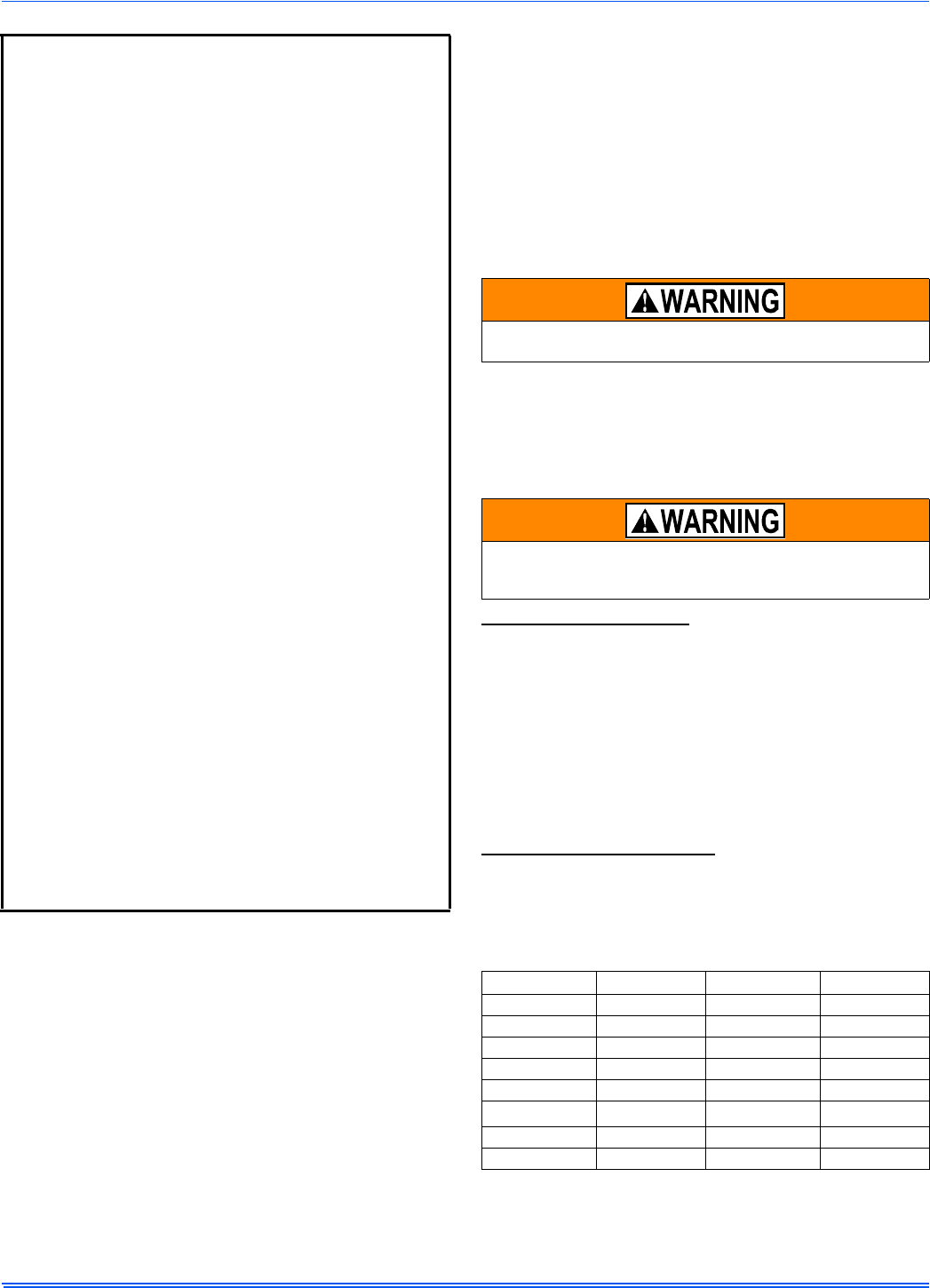
DUCT FLANGES
Four flanges are provided to attach ductwork to the furnace. These
flanges are rotated down for shipment. In order to use the flanges,
remove the screw holding an individual flange, rotate the flange so it is
in the upward position and reinstall the screw then repeat this for all 4
flanges.
If the flanges are not used, they must remain in the rotated down posi-
tion as shipped.
DUCTWORK INSTALLATION AND SUPPLY PLENUM
CONNECTION - UPFLOW/HORIZONTAL
Attach the supply plenum to the furnace outlet. The use of
an approved flexible duct connector is recommended on all
installations. This connection should be sealed to prevent
air leakage. The sheet metal should be crosshatched to
eliminate any popping of the sheet metal when the indoor
fan is energized.
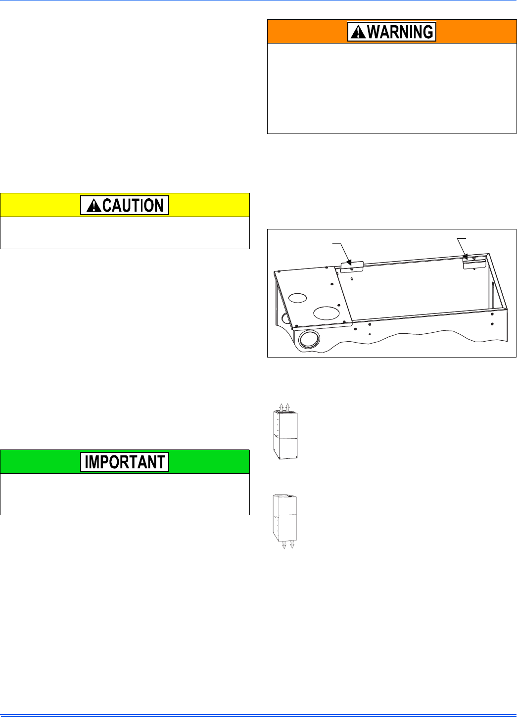
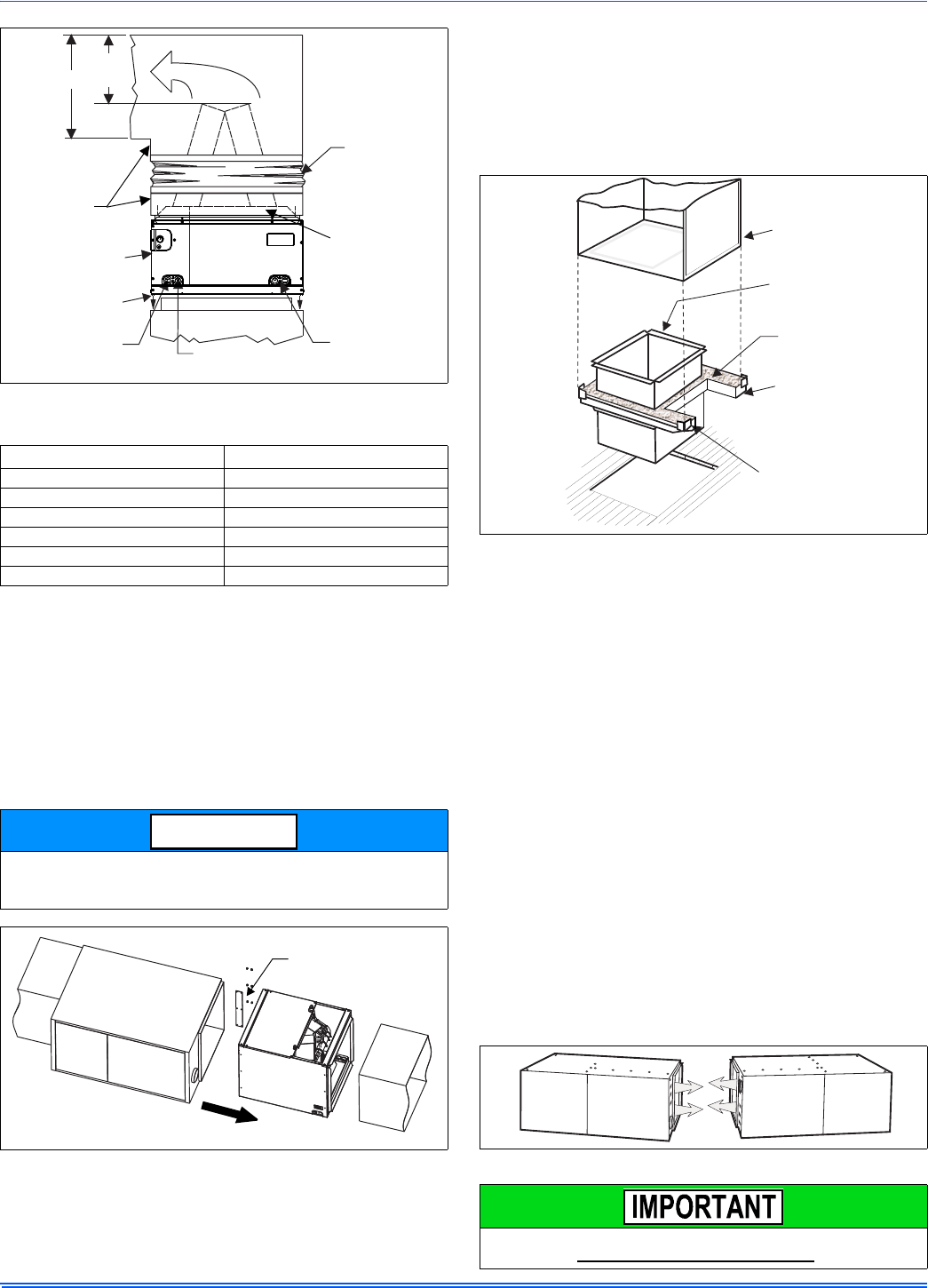
FLOOR BASE AND DUCTWORK INSTALLATION -
DOWNFLOW
Installations on combustible material or directly on any
floors must use a combustible floor base shown in Figure 8.
Follow the instructions supplied with the combustible floor
base accessory. This combustible floor base can be
replaced with a matching cooling coil, properly sealed to
prevent leaks. Follow the instructions supplied with the
cooling coil cabinet for installing the cabinet to the duct con-
nector. Plug intake and vent pipe holes in bottom panel and move grom-
met to desired vent side exit.
Downflow Air Conditioning Coil Cabinet
The furnace should be installed with coil cabinet part number specifi-
cally intended for downflow application. If a matching cooling coil is
used, it may be placed directly on the furnace outlet and sealed to pre-
vent leakage. For details of the coil cabinet dimensions and installation
requirements, refer to the installation instructions supplied with the coil
cabinet.
Attach the air conditioning coil cabinet to the duct connector, and then
position the furnace on top of the coil cabinet. The connection to the fur-
nace, air conditioning coil cabinet, duct connector, and supply air duct
must be sealed to prevent air leakage.
The cooling coil must be installed in the supply air duct, downstream
of the furnace. Cooled air may not be passed over the heat
exchanger.
The minimum plenum height is 12” (30.5 cm). The furnace will not
operate properly on a shorter plenum height. The minimum recom-
mended rectangular duct height is 4” (10.1 cm) attached to the ple-
num.
The duct system must be properly sized to obtain the correct airflow
for the furnace size that is being installed.
Refer to Table 6 or the furnace rating plate for the correct rise range
and static pressures.
If the ducts are undersized, the result will be high duct static pres-
sures and/or high temperature rises which can result in a heat
exchanger OVERHEATING CONDITION. This condition can result in
premature heat exchanger failure, which can result in personal injury,
property damage, or death.
FIGURE 1: Duct Attachment
Factory
installed
For duct attachment,
if needed.
364861-UIM-H-0712
6Johnson Controls Unitary Products
COIL INSTALLATION
COIL/FURNACE ASSEMBLY - MC/FC/PC SERIES
COILS
FURNACE ASSEMBLY - MC & FC SERIES COILS
These coils are factory shipped for installation in either upflow or down-
flow applications with no conversion.
Position the coil casing over or under the furnace opening as shown in
Figure 2 after configuring coil flanges as required see “Coil Flange” sec-
tion below.
COIL FLANGE INSTALLATION
The coils include removable flanges to allow proper fit up with furnaces
having various inlet and outlet flange configurations. The two flanges
are attached to the top of the coil in the factory during production. For
proper configuration of flanges refer to Figure 3.
FURNACE ASSEMBLY - MC SERIES COILS ONLY
MC coils are supplied ready to be installed in a horizontal position. A
horizontal pan is factory installed. MC coils should be installed in all hor-
izontal applications with the horizontal drain pan side down.
For horizontal left hand applications no conversion is required to an MC
coil when used with a downflow/horizontal furnace. A mounting plate,
supplied with every coil should always be installed on the side desig-
nated as top side. See Figures 4 & 5.
FURNACE ASSEMBLY - PC SERIES COILS
These upflow coils are designed for installation on top of upflow fur-
naces only.
If the coil is used with a furnace of a different size, use a 45° transition
to allow proper air distribution through the coil.
1. Position the coil casing over the furnace opening as shown in Fig-
ure 6.
2. Place the ductwork over the coil casing flange and secure.
3. Check for air leakage between the furnace and coil casing and seal
appropriately.
On all installations without a coil, a removable access panel is recom-
mended in the outlet duct such that smoke or reflected light would be
observable inside the casing to indicate the presence of leaks in the
heat exchanger. This access cover shall be attached in such a man-
ner as to prevent leaks.
FIGURE 2: Vertical Applications
FIGURE 3: Coil Flange
UPFLOW DOWNFLOW
Furnace
Furnace
ALTERNATE
FLANGE LOCATION
(Used for downflow or
horizontal left installations)
FACTORY
FLANGE
LOCATION
(Used for upflow
or horizontal
right installations)
FIGURE 4: Horizontal Right Application
FIGURE 5: Horizontal Left Application
Do not drill any holes or drive any screws into the front duct flange on
the coil in order to prevent damaging coil tubing. See Figure 6.
Furnace
Mounting Plate
Furnace
Mounting Plate
364861-UIM-H-0712
Johnson Controls Unitary Products 7
Dimension “C” should be at least 2/3 of dimension “D”. See Figure 6.
CRITICAL COIL PROJECTION
The coil assembly must be located in the duct such that a minimum dis-
tance is maintained between the top of the coil and the top of the duct.
Refer to Table 2.
COIL / FURNACE ASSEMBLY - HC SERIES COILS
These coils are supplied ready to be installed in a right hand position or
a left hand position. When used in conjunction with a horizontal furnace
(blow through) application, the coil should be oriented with the opening
of the “A” coil closest to the furnace. See Figure 7.
DOWNFLOW DUCT CONNECTORS
All downflow installations must use a suitable duct connector approved
by the furnace manufacturer for use with this furnace. The duct connec-
tors are designed to be connected to the rectangular duct under the
floor and sealed. Refer to the instructions supplied with the duct con-
nector for proper installation. Refer to the separate accessory parts list
at the end of these instructions for the approved accessory duct con-
nectors.
RESIDENTIAL AND MODULAR HOME UPFLOW
RETURN PLENUM CONNECTION
Return air may enter the furnace through the side(s) or bottom depend-
ing on the type of application. Return air may not be connected into the
rear panel of the unit.
SIDE RETURN APPLICATION
Side return applications pull return air through an opening cut in the
side of the furnace casing. This furnace is supplied with a bottom block-
off panel that should be left in place if a side return is to be used. If the
furnace is to be installed on a flat, solid surface, this bottom panel will
provide an adequate seal to prevent air leakage through the unused
bottom opening. However, if the furnace is to be installed on a surface
that is uneven, or if it is to be installed on blocks or otherwise raised off
the floor, it will be necessary to seal the edges of the bottom panel
to the casing using tape or other appropriate gasket material to
prevent air leakage.
BOTTOM RETURN AND ATTIC INSTALLATIONS
Bottom return applications normally pull return air through a base plat-
form or return air plenum. Be sure the return platform structure or return
air plenum is suitable to support the weight of the furnace.
The internal bottom panel must be removed for this application.
Attic installations must meet all minimum clearances to combustibles
and have floor support with required service accessibility.
HORIZONTAL APPLICATION
FIGURE 6: PC Series Upflow Coil Installation
Table 2: Coil Projection Dimensions - PC Series Coils
COIL SIZE DIMENSION “C” INCH
PC18 3-1/2
PC24 4-1/2
PC30, PC32, PC35 4-1/2
PC42, PC43, PC36, PC37 5-1/2
PC48 6-1/2
PC60 9
Each coil is shipped with an external tie plate that should be used to
secure the coil to the furnace. It should be installed on the back side
of the coil using the dimpled pilot holes. See Figure 7.
FIGURE 7: Horizontal Left or Right application (Right Shown)
Flexible
Duct Collar
Do not drill
or Screw
this flange
Field
Fabricated
Ductwork
Upflow
Coil
Upflow
Furnace
Secondary
Drain
Primary
Drain
D
C
(Min)
Alternate
Drain Location
NOTICE
Use tie plate
supplied with coil
Air flow
Gas Furnace
FIGURE 8: Combustible Floor Base Accessory
FIGURE 9: Horizontal Application
This furnace may be installed in a horizontal position on either side as
shown above. It must not be installed on its back.
FURNACE
WARM AIR PLENUM
WITH 1” FLANGES
FIBERGLASS
INSULATION
FIBERGLASS TAPE
UNDER FLANGE
COMBUSTIBLE FLOOR
BASE ACCESSORY
364861-UIM-H-0712
8Johnson Controls Unitary Products
ATTIC INSTALLATION
This appliance is certified for line contact when the furnace is installed
in the horizontal left or right position. The line contact is only permissible
between lines that are formed by the intersection of the top and two
sides of the furnace and the building joists, studs or framing. This line
may be in contact with combustible material. Refer to Figure 10.
When moving or handling this furnace prior to installation, always leave
the doors on the furnace to provide support and to prevent damage or
warping of the cabinet. When lifting the furnace, support the ends of the
furnace rather than lifting by the cabinet flanges at the return air open-
ings (bottom or sides) or supply air opening.
It is acceptable to use the primary heat exchanger tubes as a lifting
point provided that the tubes are lifted at the front of the heat exchang-
ers where attached to the vestibule panel. Do not use the top return
bend of the heat exchangers as lifting points as the tubes may shift out
of position or their location brackets/baffles.
SUSPENDED FURNACE / CRAWL SPACE
INSTALLATION
The furnace can be hung from floor joists or installed on suitable blocks
or pads. Blocks or pad installations shall provide adequate height to
ensure that the unit will not be subject to water damage.
Units may also be suspended from rafters or floor joists using rods, pipe
angle supports or straps. In all cases, the furnace should be supported
with rods, straps, or angle supports at three locations to properly sup-
port the furnace. Place one support at the supply end of the furnace,
one support located approximately in the center of the furnace near the
blower shelf, and the third support should be at the return end of the fur-
nace. Maintain a 6” (15.2 cm) minimum clearance between the front of
the furnace and the support rods or straps.
All six suspension points must be level to ensure proper and quiet fur-
nace operation. When suspending the furnace, use a secure platform
constructed of plywood or other building materials secured to the floor
or ceiling joists. Refer to Figure 11 for details and additional information.
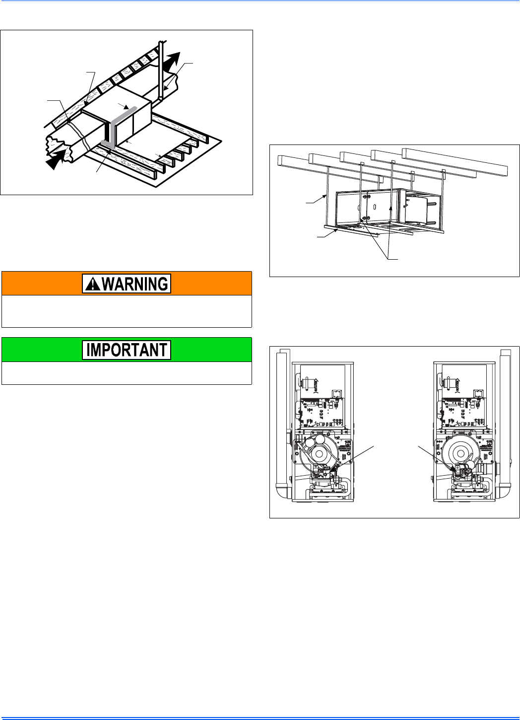
DOWNFLOW APPLICATION
To apply the furnace in a downflow position, it will be necessary to
rotate the vent blower 90° left or right so that the vent pipe passes
through the side of the furnace casing. See Figure 12.
FIGURE 10: Typical Attic Installation
When a furnace is installed in an attic or other insulated space, keep
all insulating materials at least 12” (30.5 cm) away from furnace and
burner combustion air openings.
During installation, doors should remain on the furnace when
moving or lifting.
Return
Air Sediment
Trap
Gas Piping
Supply
Air Vent (Maintain
required
clearances to
combustibles)
Line contact only permissible
between lines formed by the
intersection of furnace top
and two sides and building
joists, studs or framing
30” MIN.
Work Area
Filter rack
must be a minimum
distance
of 18” (45.7 cm)
from the
furnace
FIGURE 11: Typical Suspended Furnace / Crawl Space Installation
FIGURE 12: Downflow Venting
Support
Rod
Support
Angle (x3) Maintain 6” minimum
clearance between support
rods and front of furnace
LEFT SIDE VENT RIGHT SIDE VENT
Rotate vent
blower 90°
either way
364861-UIM-H-0712
Johnson Controls Unitary Products 9
SECTION III: FILTERS
FILTER INSTALLATION
All applications require the use of a field installed filter. All filters and
mounting provision must be field supplied.
Filters must be installed external to the furnace cabinet. DO NOT
attempt to install filters inside the furnace.
1. Air velocity through throwaway type filters may not exceed 300 feet per min-
ute (91.4 m/min). All velocities over this require the use of high velocity fil-
ters.
2. Do not exceed 1800 CFM using a single side return and a 16x25 filter. For
CFM greater than 1800, you may use two side returns or one side and the
bottom or one side return with a transition to allow use of a 20x25 filter.
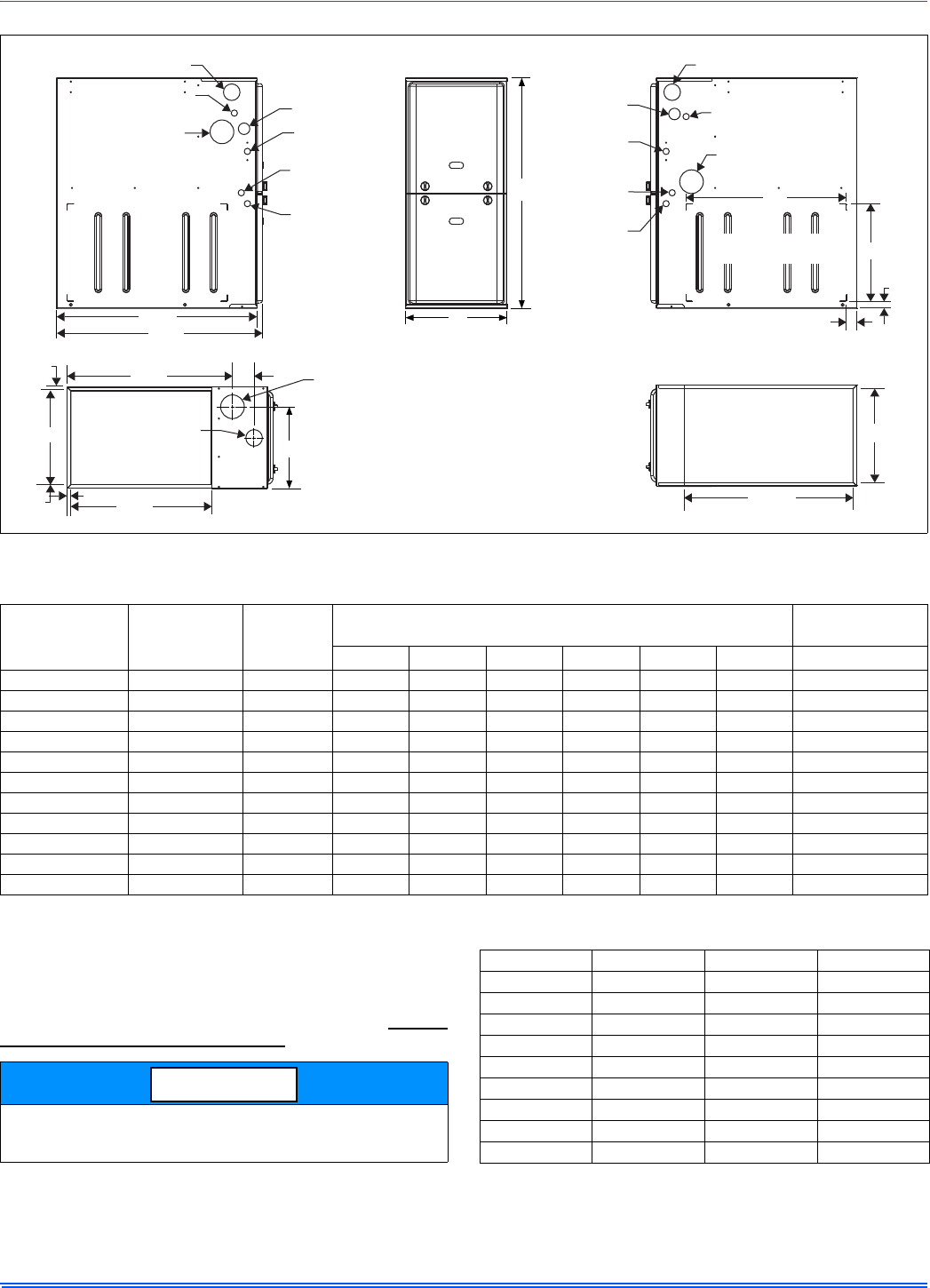
FIGURE 13: Dimensions
FRONT
33
A
LEFT SIDE
Combustion Air Inlet
Condensate Drain
(Downflow)
Vent Outlet
Thermostat
Wiring
28.5”
Gas Pipe
Entry
Electrical
Entry
Condensate
Drain
Thermostat
Wiring
RIGHT SIDE
Vent Outlet
Condensate Drain
(Downflow)
14”
1”
1.5”
23”
Combustion Air Inlet
Gas Pipe
Entry
Electrical
Entry
Condensate
Drain
Optional Return Air
Cutout (Either side)
29.5”
(For Cladded door add appoximately an additional .75”)
C
SUPPLY END
.56”
.56”
20”
B
3”
23.8”
.56”
Combustion
Air Inlet
Vent
Outlet
RETURN END
B
24.25”
Table 3: Cabinet and Duct Dimensions
BTUH (kW)
Input
Nominal
CFM (m3/min)
Cabinet
Size
Cabinet Dimensions (Inches) Approximate
Operating Weights
A (in) A (cm) B (in) B (cm) C (in) C (cm) Lbs (kg)
40 (11.7) 800 (22.7) A 14 1/2 36.8 13 3/8 34.0 11 3/4 29.8 113 (51.3)
60 (17.6) 1000 (28.3) A 14 1/2 36.8 13 3/8 34.0 11 3/4 29.8 118 (53.5)
60 (17.6) 1200 (34.0) B 17 1/2 44.4 16 3/8 41.6 13 1/4 33.7 122 (55.3)
80 (23.4) 1200 (34.0) B 17 1/2 44.4 16 3/8 41.6 14 3/4 37.5 126 (57.2)
80 (23.4) 1600 (45.3) C 21 53.3 19 7/8 50.5 16 1/2 41.9 136 (61.7)
80 (23.4) 2200 (62.3) C 21 53.3 19 7/8 50.5 16 1/2 41.9 139 (63.0)
100 (29.3) 1600 (45.3) C 21 53.3 19 7/8 50.5 18 1/4 46.4 142 (64.4)
100 (29.3) 2000 (56.6) C 21 53.3 19 7/8 50.5 18 1/4 46.4 145 (65.8)
120 (35.1) 1600 (45.3) D 24 1/2 62.2 23 3/8 59.4 21 3/4 55.2 153 (69.4)
120 (35.1) 2000 (56.6) D 24 1/2 62.2 23 3/8 59.4 21 3/4 55.2 156 (70.7)
130 (38.1) 2000 (56.6) D 24 1/2 62.2 23 3/8 59.4 No Hole No Hole 160 (72.5)
Single side return above 1800 CFM is approved as long as the filter
velocity does not exceed filter manufacturer’s recommendation and a
transition is used to allow use on a 20x25 filter.
NOTICE
Table 4: Recommended Filter Sizes (High Velocity 600 FPM)
CFM (m³/min) Cabinet Size Side (in) Bottom (in)
800 (22.7) A 16 x 25 14 x 25
1000 (28.3) A 16 x 25 14 x 25
1200 (34.0) A 16 x 25 14 x 25
1200 (34.0) B 16 x 25 16 x 25
1600 (45.3) B 16 x 25 16 x 25
1600 (45.3) C 16 x 25 20 x 25
2000 (56.6) C (2) 16 x 25 20 x 25
2200 (62.3) C (2) 16 x 25 20 x 25
2000 (56.6) D (2) 16 x 25 22 x 25
364861-UIM-H-0712
10 Johnson Controls Unitary Products
SIDE RETURN
Locate the “L” shaped corner locators. These indicate the size of the cut-
out to be made in the furnace side panel. Refer to Figure 14.
Install the side filter rack following the instructions provided with that
accessory. If a filter(s) is provided at another location in the return air
system, the ductwork may be directly attached to the furnace side
panel.
HORIZONTAL APPLICATION
Horizontal Filters
Any branch duct (rectangular or round duct) attached to the plenum
must attach to the vertical plenum before the filter. The use of straps
and/or supports is required to support the weight of the external filter
box.
Downflow Filters
Downflow furnaces typically are installed with the filters located above
the furnace, extending into the return air plenum or duct. Any branch
duct (rectangular or round duct) attached to the plenum must attach to
the vertical plenum above the filter height.
Filter(s) may be located in the duct system external to the furnace using
an external duct filter box attached to the furnace plenum or at the end
of the duct in a return filter grille(s). The use of straps and/or supports is
required to support the weight of the external filter box.
SECTION IV: GAS PIPING
GAS SAFETY
GAS PIPING INSTALLATION
Properly sized wrought iron, approved flexible or steel pipe must be
used when making gas connections to the unit. If local codes allow the
use of a flexible gas appliance connection, always use a new listed con-
nector. Do not use a connector that has previously serviced another gas
appliance.
Some utility companies or local codes require pipe sizes larger than the
minimum sizes listed in these instructions and in the codes. The furnace
rating plate and the instructions in this section specify the type of gas
approved for this furnace - only use those approved gases. The instal-
lation of a drip leg and ground union is required. Refer to Figure 16.
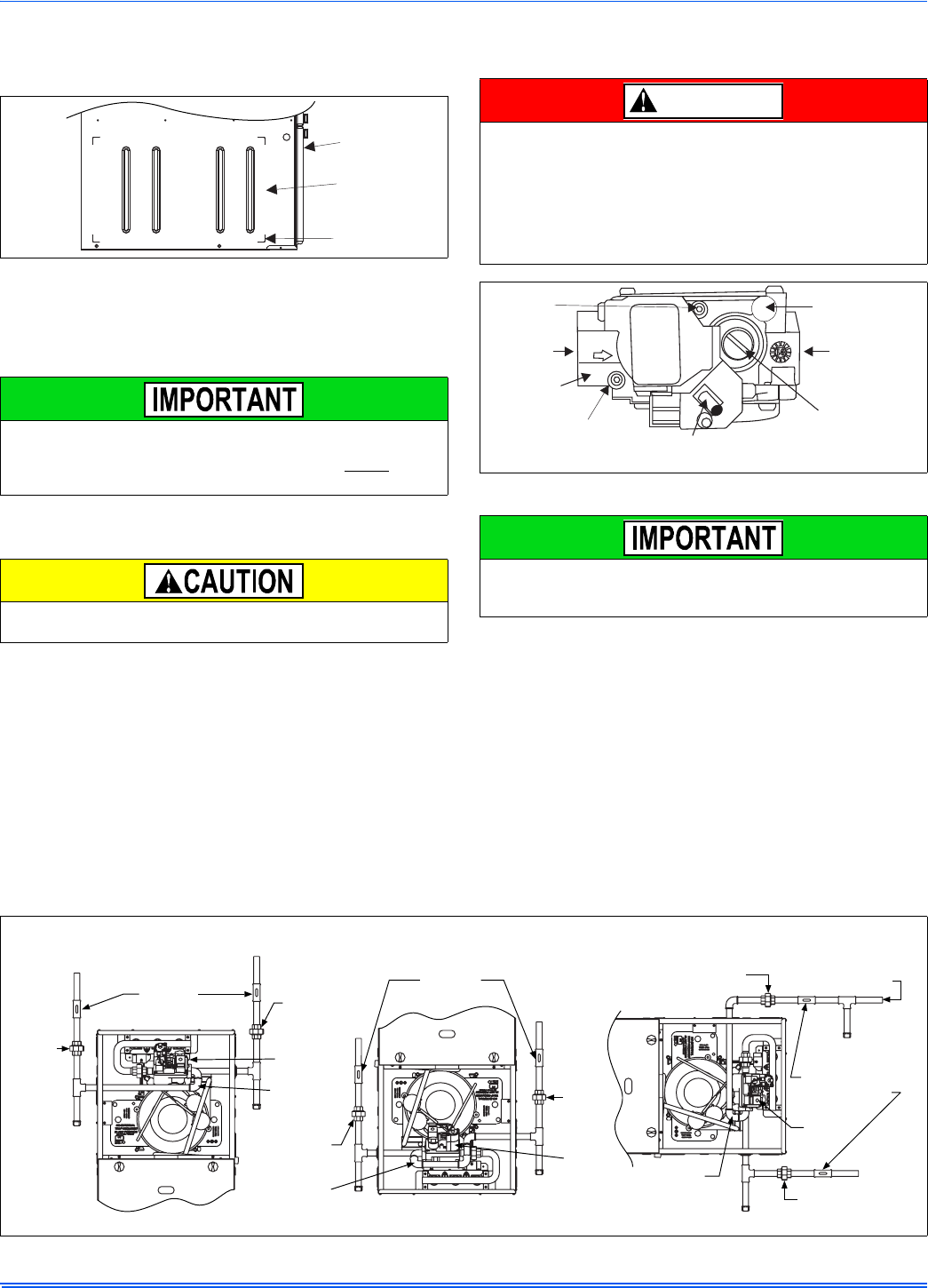
FIGURE 14: Side Return Cutout Markings
Some accessories such as electronic air cleaners and pleated media
may require a larger side opening. Follow the instructions supplied
with that accessory for side opening requirements. Do not cut the
opening larger than the dimensions shown in Figure 13.
All filters and mounting provision must be field supplied. All installa-
tions must have a filter installed.
Front of
Furnace
Corner
Markings
Side of
Furnace
An overpressure protection device, such as a pressure regulator,
must be installed in the gas piping system upstream of the furnace
and must act to limit the downstream pressure to the gas valve so it
does not exceed 0.5 psig [14" w.c. (3.48 kPa)]. Pressures exceeding
0.5 psig [14” w.c. (3.48 kPa)] at the gas valve will cause damage to
the gas valve, resulting in a fire or explosion or cause damage to the
furnace or some of its components that will result in property damage
and loss of life.
FIGURE 15: Gas Valve
Plan your gas supply before determining the correct gas pipe entry.
Use 90° service elbow(s), or short nipples and conventional 90°
elbow(s) to enter through the cabinet access holes.
DANGER
INLET
WRENCH
BOSS
INLET
PRESSURE
PORT
ON
OFF
ON/OFF SWITCH
(Shown in ON position)
MAIN REGULATOR
ADJUSTMENT
OUTLET
OUTLET
PRESSURE
PORT
VENT PORT
FIGURE 16: Gas Piping
Upflow Downflow Horizontal
External
Manual
Shut-off
Valve
External
Manual
Shut-off
Valve
External Manual
Shut-off Valve
To Gas
Supply
To Gas
Supply
To Gas
Supply
To Gas
Supply
To Gas
Supply
To Gas
Supply
Drip
Leg
Drip
Leg
Drip
Leg
Drip
Leg
Drip Leg
Drip
Gas
Pipe
Gas
Valve
Gas
Pipe
Gas
Valve
Gas
Pipe
Gas
Valve
Ground
Union
Ground
Union
Ground
Union
Ground
Union
Ground
Union
Ground
Union
NOTE: Ground Union maybe installed inside or outside unit.
364861-UIM-H-0712
Johnson Controls Unitary Products 11
The furnace must be isolated from the gas supply piping system by
closing its individual external manual shutoff valve during any pressure
testing of the gas supply piping system at pressures equal to or less
than 0.5 psig (3.5 kPa).
Gas piping may be connected from either side of the furnace using any
of the gas pipe entry knockouts on both sides of the furnace. Refer to
Figure 13.
GAS ORIFICE CONVERSION FOR PROPANE (LP)
This furnace is constructed at the factory for natural gas-fired operation,
but may be converted to operate on propane (LP) gas by using a fac-
tory-supplied LP conversion kit. Follow the instructions supplied with
the LP kit.
HIGH ALTITUDE GAS ORIFICE CONVERSION
This furnace is constructed at the factory for natural gas-fired operation
at 0 –7,999 feet (0 – 2,438 m) above sea level.
The manifold pressure must be changed in order to maintain proper
and safe operation when the furnace is installed in a location where the
altitude is greater than 7,999 feet (2,438 m) above sea level. Refer to
Table 5 for proper manifold pressure settings.
HIGH ALTITUDE PRESSURE SWITCH CONVERSION
For installation where the altitude is less than 5,000 feet (1,524m), it is
not required that the pressure switch be changed unless you are in an
area subject to low pressure inversions.
SECTION V: ELECTRICAL POWER
ELECTRICAL POWER CONNECTIONS
Field wiring to the unit must be grounded. Electric wires that are field
installed shall conform to the temperature limitation for 63°F (35°C) rise
wire when installed in accordance with instructions. Refer to Table 6 in
these instructions for specific furnace electrical data.
An accessible manual shutoff valve must be installed upstream of the
furnace gas controls and within 6 feet (1.8 m) of the furnace.
The gas valve body is a very thin casting that cannot take any exter-
nal pressure. Never apply a pipe wrench to the body of the gas valve
when installing piping. A wrench must be placed on the octagon hub
located on the gas inlet side of the valve. Placing a wrench to the
body of the gas valve will damage the valve causing improper opera-
tion and/or the valve to leak.
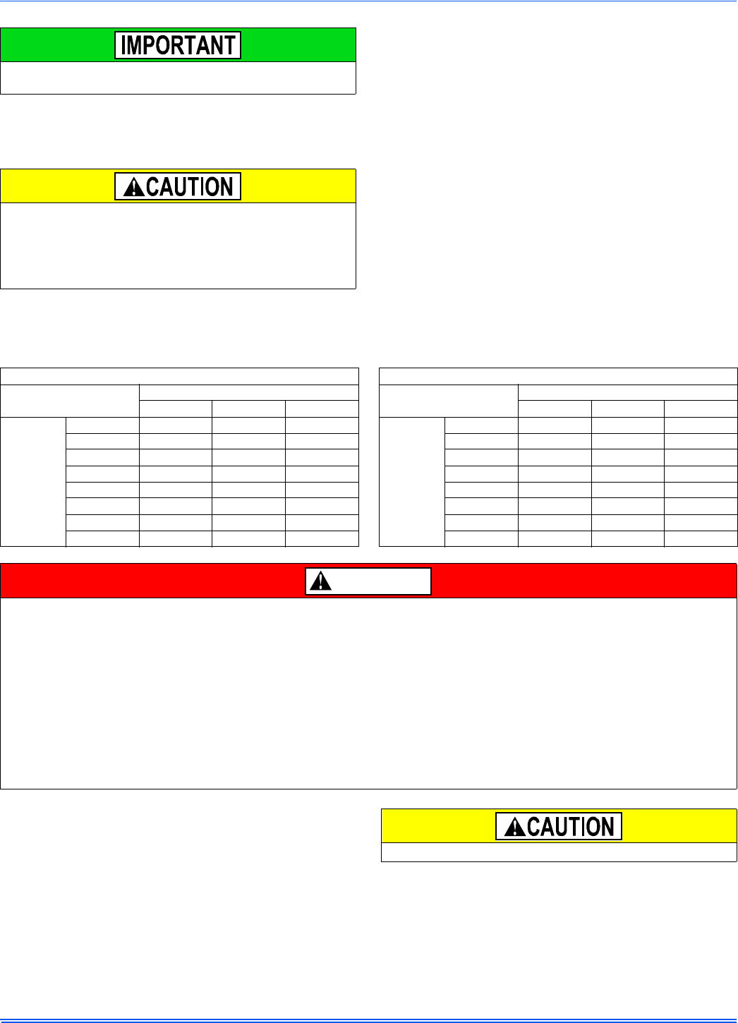
Table 5: Nominal Manifold Pressure - High Fire
Manifold Pressures (in. w.c.) Manifold Pressures (kPa)
Altitude (feet) Altitude (m)
0-7999 8000-8999 9000-9999 0-2437 2438-2742 2743-3048
Gas Heating Value
(BTU/cu ft.)
800 3.5 3.5 3.5
Gas Heating Value
(MJ/cu m)
29.8 0.87 0.87 0.87
850 3.5 3.5 3.5 31.7 0.87 0.87 0.87
900 3.5 3.5 3.5 33.5 0.87 0.87 0.87
950 3.5 3.5 3.3 35.4 0.87 0.87 0.81
1000 3.5 3.2 2.9 37.3 0.87 0.80 0.73
1050 3.5 2.9 2.7 39.1 0.87 0.73 0.67
1100 3.2 2.7 2.4 41.0 0.80 0.66 0.61
2500 (LP) 9.8 8.2 7.5 93.2 (LP) 2.44 2.03 1.86
PROPANE AND HIGH ALTITUDE CONVERSION KITS
It is very important to choose the correct kit and/or gas orifices for the altitude and the type of gas for which the furnace is being installed.
Only use natural gas in furnaces designed for natural gas. Only use propane (LP) gas for furnaces that have been properly converted to use pro-
pane (LP) gas. Do not use this furnace with butane gas.
Incorrect gas orifices or a furnace that has been improperly converted will create an extremely dangerous condition resulting in premature heat
exchanger failure, excessive sooting, high levels of carbon monoxide, personal injury, property damage, a fire hazard and/or death.
High altitude and propane (LP) conversions are required in order for the appliance to satisfactory meet the application.
An authorized distributor or dealer must make all gas conversions.
In Canada, a certified conversion station or other qualified agency, using factory specified and/or approved parts, must perform the conversion.
The installer must take every precaution to insure that the furnace has been converted to the proper gas orifice size when the furnace is installed.
Do not attempt to drill out any orifices to obtain the proper orifice size. Drilling out a gas orifice will cause misalignment of the burner flames, caus-
ing premature heat exchanger burnout, high levels of carbon monoxide, excessive sooting, a fire hazard, personal injury, property damage and/or
death.
DANGER
Use copper conductors only.
364861-UIM-H-0712
12 Johnson Controls Unitary Products
Annual Fuel Utilization Efficiency (AFUE) numbers are determined in accordance with DOE Test procedures.
Wire size and over current protection must comply with the National Electrical Code (NFPA-70-latest edition) and all local codes.
The furnace shall be installed so that the electrical components are protected from water.
SUPPLY VOLTAGE CONNECTIONS
1. Provide a power supply separate from all other circuits. Install over-
current protection and disconnect switch per local/national electrical
codes. The switch should be close to the unit for convenience in
servicing. With the disconnect or fused switch in the OFF position,
check all wiring against the unit wiring label. Refer to the wiring dia-
gram in this instruction.
2. Remove the wiring box cover screws. Route all power wiring
through a conduit connector or other proper bushing that has been
installed into the unit opening and the junction box. In the junction
box there is a black wire, a white wire and a green ground screw.
Connect the power supply as shown on the unit’s wiring label on
the inside of the blower compartment door or the wiring schematic
in this section. Connect the black wire to L1 (hot) from the power
supply. Connect the white wired to neutral. Connect the ground wire
(installer-supplied) to the green (equipment ground) screw. An
alternate wiring method is to use a field-provided 2” (5.1 cm) x 4”
(10.2 cm) box and cover on the outside of the furnace. Route the
furnace leads into the box using a protective bushing where the
wires pass through the furnace panel. After making the wiring con-
nections replace the wiring box cover and screws. Refer to Figure
17.
3. The furnace's control system requires correct polarity of the power
supply and a proper ground connection. Refer to Figure 17.
LOW VOLTAGE CONTROL WIRING CONNECTIONS
Install the field-supplied thermostat by following the instructions that
come with the thermostat. With the thermostat set in the OFF position
and the main electrical source disconnected, connect the thermostat
wiring from the wiring connections on the thermostat to the terminal
board on the ignition module, as shown in Figure 17. Electronic thermo-
stats may require the common wire to be connected. Apply strain relief
to thermostat wires passing through cabinet. If air conditioning equip-
ment is installed, use thermostat wiring to connect the Y and C termi-
nals on the furnace control board to the proper wires on the condensing
unit (unit outside).
The 24-volt, 40 VA transformer is sized for the furnace components
only, and should not be connected to power auxiliary devices such as
humidifiers, air cleaners, etc. The transformer may provide power for an
air conditioning unit contactor.
Table 6: Ratings & Physical / Electrical Data
Input Output Nominal
Airflow AFUE
%
Air Temp. Rise Max. Outlet
Air Temp Blower Blower
Size
Max
Over-Current
Protect
Total Unit
Amps
Min. wire Size
(awg) @ 75 ft
one way
MBH kW MBH kW CFM m3/min °F °C °F °C HP Amps
40 11.7 38 11.1 800 22.7 95.5 30-60 17-33 160 71.1 1/3 4.8 11x8 15 8.0 14
60 17.6 57 16.7 1000 28.3 95.5 30-60 19-36 160 71.1 1/2 7.07 11x8 15 10.0 14
60 17.6 57 16.7 1200 34.0 95.5 30-60 19-36 160 71.1 1/2 7.07 11x8 15 10.0 14
80 23.4 76 22.3 1200 34.0 95.5 35-65 19-36 165 73.9 1/2 7.07 11x8 15 10.0 14
80 23.4 76 22.3 1600 45.3 95.5 35-65 19-36 165 73.9 3/4 8.8 11x10 15 11.5 14
80 23.4 76 22.3 2200 62.3 95.5 35-65 19-36 165 73.9 1 14.5 11x11 20 17.0 12
100 29.3 95 27.8 1600 45.3 95.5 35-65 19-36 165 73.9 3/4 8.8 11x10 15 11.5 14
100 29.3 95 27.8 2000 56.6 95.5 35-65 19-36 165 73.9 1 14.5 11x11 20 17.0 12
120 35.1 114 33.4 1600 45.3 95.5 40-70 22-39 170 76.7 3/4 8.8 11x10 15 11.5 14
120 35.1 114 33.4 2000 56.6 95.5 35-65 19-36 165 73.9 1 14.5 11x11 20 17.0 12
130 38.1 123.5 36.2 2000 56.6 95.5 45-75 28-44 175 79.4 1 14.5 11x11 20 17.0 12
FIGURE 17: Electrical Wiring
Electrical Entry
Junction
Box
L1-Hot
Neutral
Connect ground
lead to screw
BLK
WHT
The power connection leads and wiring box may be relocated to the
left side of the furnace. Remove the screws and cut wire tie holding
excess wiring. Reposition on the left side of the furnace and fasten
using holes provided.
Set the heat anticipator in the room thermostat to 0.4 amps. Setting it
lower will cause short cycles. Setting it higher will cause the room
temperature to exceed the set points.
Some electronic thermostats do not have adjustable heat anticipa-
tors. They should be set to six cycles per hour. Follow the thermostat
manufacturer's instructions.
364861-UIM-H-0712
Johnson Controls Unitary Products 13
For additional connection diagrams for all UPG equipment refer to “Low Voltage System Wiring” document available on-line at www.upgnet.com in
the Product Catalog Section.
FIGURE 18: Thermostat Chart - Single Stage AC with Single Stage PSC Furnaces
AC 5D Single Stage Air Conditioner – Single Stage PSC Furnace
HM1
Humidistat
Y
Full Stage Compressor
G
Fan
*PP11C70224
THERMOSTAT
RH
24 – Volt Hot
(Heat XFMR)
RC
24 – Volt Hot
(Cool XFMR)
W
Full Stage Heat
Clipping Jumper W914 for
electric heat on thermostat
is not necessary
24VAC Humidifier
(Optional)
C
24 – Volt Common
Y
Compressor
SINGLE STAGE
AIR CONDITIONER
Y
Compressor Contactor
SINGLE STAGE
AIR
CONDITIONER
SINGLE STAGE
AIR CONDITIONER
G8C
L(Y/M)8S
G*9F
G*(8/9)S
ID MODELS
(G/T)GLS
(G,T)G(8/9)S
LF8
GF(8/9)
C
24 – Volt Common
R
24 – Volt Hot
W
Full Stage Heat
SINGLE STAGE PSC
FURNACE
G
Fan
SINGLE STAGE
PSC
FURNACE
Other Part Numbers:
SAP = Legacy
265901 = 031-09166
1
1
Y/Y2
Full Stage Compressor
364861-UIM-H-0712
14 Johnson Controls Unitary Products
FIGURE 19: Thermostat Chart - Single Stage HP with Single Stage PSC Furnaces
HP 2C Single Stage Heat Pump – Single Stage PSC Furnace
C
24 – Volt Common
R
24 – Volt Hot
Y1
First Stage Compressor
O
Reversing Valve
Energized in Cool
L
Malfunction Light
G
Fan
*DP32H70124
THERMOSTAT
W1
Second Stage Aux. Heat
E
Emergency Heat
W2
Third Stage Heat
N/A
*BP21H50124
*BN21H00124
*DP21H40124
*DN21H00124
THERMOSTAT
N/A
*DN22U00124
THERMOSTAT
Part Numbers:
SAP = Legacy
67297 = 031-01975
E*B*
E*ZD
E*R*
OD MODELS
*HGD
HP*
*RHS
O
Reversing Valve
Energized in Cool
C
24 – Volt Common
R
24 – Volt Hot
W1/66(out)
Heat
Y
Compressor
DEMAND DEFROST
CONTROL
X/L
Malfunction Light
W
Auxiliary Heat
SINGLE STAGE
HEAT PUMP
1
1
Part Number:
S1-2HU16700124
3
24VAC Humidifier
(Optional)
External Humidistat
(Optional)
Open on Humidity Rise
3
Y2
Second Stage Compressor
Step 9 of Thermostat
Installer / Configuration
Menu must be set to
Pump OFF
Step 1 of Thermostat
Installer / Configuration
Menu must be set to
Heat Pump 1
G8C
L(Y/M)8S
G*9F
G*(8/9)S
ID MODELS
(G/T)GLS
(G,T)G(8/9)S
LF8
GF(8/9)
C
24 – Volt Common
R
24 – Volt Hot
W
Full Stage Heat
SINGLE STAGE PSC
FURNACE
G
Fan
SINGLE STAGE
PSC
FURNACE
Other Part Numbers:
SAP = Legacy
265901 = 031-09166
2
2
Y/Y2
Full Stage Compressor

364861-UIM-H-0712
Johnson Controls Unitary Products 15
ACCESSORY CONNECTIONS
The furnace control will allow power-switching control of various acces-
sories.
ELECTRONIC AIR CLEANER CONNECTION
Two 1/4” (6.4 mm) spade terminals (EAC and NEUTRAL) for electronic
air cleaner connections are located on the control board. The terminals
provide 115 VAC (1.0 amp maximum) during circulating blower opera-
tion.
HUMIDIFIER CONNECTION
Two 1/4” (6.4 mm) spade terminals (HUM and NEUTRAL) for humidifier
connections are located on the control board. The terminals provide 115
VAC (1.0 amp maximum) during heating system operation.
A mounting hole is provided on the control panel next to the furnace
control board for mounting a humidifier transformer if required.
SECTION VI: TWINNING AND STAGING
In applications where more heating capacity or more airflow capacity is
needed than what one furnace can deliver, twinning can be used to
make two furnaces operate in tandem. When two furnaces are installed
using the same duct system, it is very important that the two furnace cir-
culating air blowers operate in unison. If one blower starts before the
second blower, the duct system will become pressurized and the blower
on the second furnace will turn backwards causing the second furnace
to overheat, resulting in damage to the furnace. Twinning is used to
make two furnaces operate in tandem, using one duct system, one
room thermostat and causing both furnaces to turn on and off simulta-
neously.
TWINNING DUCT SYSTEM
Twinned furnaces must only be applied on a common duct system. A
single air supply plenum must be used for both furnaces and coil(s).
Separate plenums and supply ducts systems cannot be utilized. A sin-
gle return air plenum, common to both furnaces must be used. It is sug-
gested that a return platform be utilized, with bottom air entrance into
each furnace. If a side entrance returns system is used, the common
return duct must be divided equally so as to supply each furnace with
an equal amount of return air.
Both furnaces must be identical models in both heating capacity and
CFM capacity. Both furnaces must be operated on the same motor
speed tap. See typical application, Figure 20.
If furnace staging is desired with two single stage furnaces on a com-
mon duct, where the gas burner on the first furnace operates on W1
and the gas burner on the second furnace operates on W2, then the
use of an air-mixing device in the plenum to mix the air from both fur-
naces is strongly recommended. The mixing device must be installed
before any ducts that supply air to occupied spaces. Twinning causes
both indoor fans to operate simultaneously. If a mixing device is not
used, any ducts that are connected down stream from the furnace that
operates on W2, will be supplying cold air in the Heating mode to the
occupied spaces unless W2 is energized.
GAS PIPING
Furnace gas supplies must be provided as specified with these instruc-
tions. Since the furnaces are side by side, with no space between, gas
supplies must enter on the right and left respectively. All gas piping
must be in accordance with the national fuel gas code, ANSI Z223.1,
latest edition, and/or all local code or utility requirements.
TWINNING
In applications where more heating capacity or more airflow capacity is
needed than what one furnace can deliver, twinning can be used to
make two furnaces operate in tandem, using one duct system and one
room thermostat. When one duct system is used for two furnaces, it is
necessary that the two blowers operate in unison. The twinning function
of the board in this furnace ensures that both blowers turn on and off
simultaneously, and operate on the same blower speed.
The control in the furnace has the single-wire twinning feature. With this
feature, a wire is connected between the TWIN terminal on one furnace
board to the TWIN terminal on the second furnace board. The board
then communicates the blower status from one furnace to the other
along this wire. This communication makes the second furnace blower
come on at the same time, and on the same speed, as the first furnace
blower. To ensure stable communication, the common terminal of each
control must be connected.
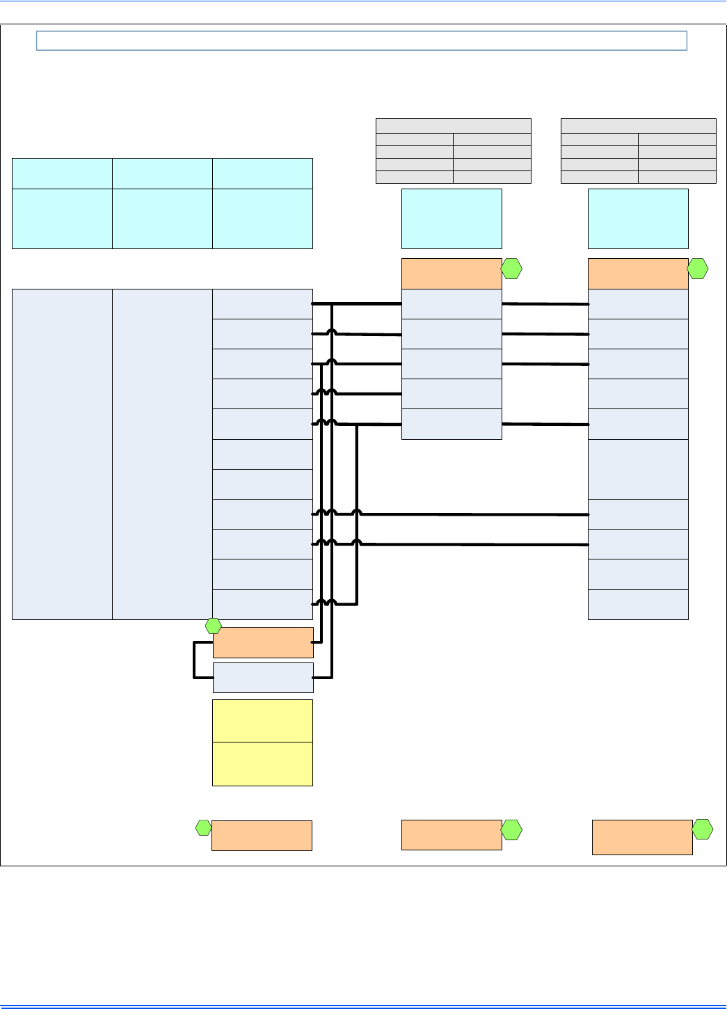
Twinning Instructions
Connect the control wiring as shown in Figure 21.
1. Connect the low voltage wiring from the wall thermostat to the ter-
minal strip on the control board of Furnace #1.
2. Connect a wire from the TWIN terminal of Furnace #1 to the TWIN
terminal of Furnace #2.
3. Install a separate 24V relay as shown in the diagram below. Use of
this relay is required, as it ensures that the transformers of the two
furnaces are isolated, thus preventing the possibility of any safety
devices being bypassed.
4. Connect the 24V common wires of furnace #1 to the 24V common
terminal of furnace #2.
Before installing the relay and wiring, disconnect electrical power to
both furnaces. Failure to cut power could result in electrical shock or
equipment damage.
The relay must not be installed in any location where it could be
exposed to water. If the relay has been exposed to water in any way,
it must not be used.
FIGURE 20: Typical Twinned Furnace Application
When two furnaces are twinned, typical system total airflow will be
approximately 85% of additive individual furnaces, i.e., two 2000 CFM
units will yield a total 3400 CFM.
If a return duct is connected to only one furnace (with a connection
between the two furnaces) an imbalance in the airflow will occur and
the furnace furthest from the return plenum will overheat.
Vent Pipe
Electrical
Supply
Gas Supply
(Both sides)
1 Coil for
Each Furnace
COMMON
SUPPLY
PLENUM
Supply
Air
364861-UIM-H-0712
16 Johnson Controls Unitary Products
Twinning Operation
Heating - On a call for heat (W signal) from the wall thermostat, both
furnaces will start the ignition sequence and the burners on both fur-
naces will light. About thirty seconds after the burners light, the blowers
on both furnaces will come on in heating speed. When the thermostat is
satisfied, the burners will all shut off and, after the selected blower off
delay time, both blowers will shut off at the same time. The twinning
control ensures that both blowers come on and shut off at the same
time.
Cooling - On a call for cooling (Y signal) from the wall thermostat, both
furnace blowers will come on at the same time in cooling speed. When
the thermostat is satisfied, both blowers will stay on for 60 seconds,
then will shut off at the same time.
Continuous Fan - On a thermostat call for continuous fan (G signal),
both furnace blowers will come on at the same time in cooling speed
and will stay on until the G signal is removed.
STAGING
This control can also be used along with a two-stage wall thermostat to
stage two twinned furnaces, making them operate like a single two-
stage furnace. This allows only one furnace to supply heat during times
when the heat output from one furnace is sufficient to satisfy the
demand. When one duct system is used for two furnaces, it is neces-
sary that the two blowers operate in unison. The twinning function of
this board ensures that both blowers turn on and off simultaneously,
and operate on the same blower speed. Even when only one furnace is
supplying heat, both furnace blowers must run.
The twinning feature of this board can also be used for staging of two
furnaces. With this feature, a single wire is connected between the
TWIN terminal on one furnace board to the TWIN terminal on the sec-
ond furnace board. The board then communicates the blower status
from one furnace to the other along this wire. This communication
makes the second furnace blower come on at the same time, and on
the same speed, as the first furnace blower. To ensure stable communi-
cation, the common terminal of each control must be connected.
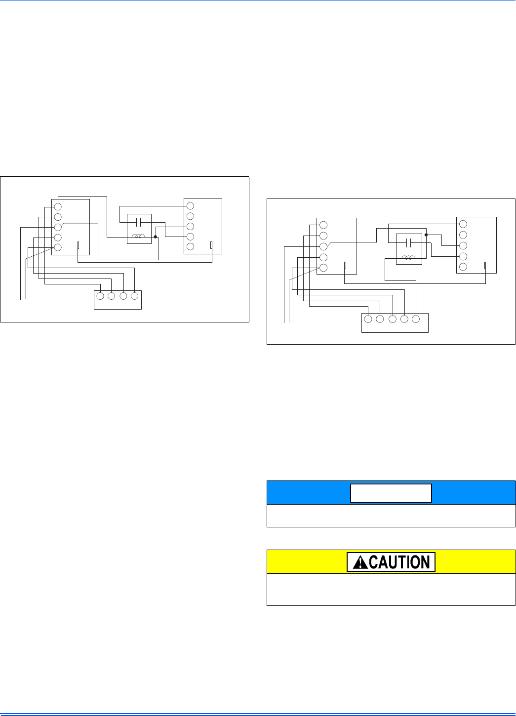
Staging Instructions
Connect the control wiring as shown in Figure 22.
1. Connect the low voltage wiring from the wall thermostat to the ter-
minal strip on the control board of Furnace #1. For staging applica-
tions, the wire from thermostat W1 is connected to the W
connection on the board on Furnace #1. The wire from thermostat
W2 is connected to Furnace #2 through a separate relay, as
described below.
2. Connect a wire from the TWIN terminal of Furnace #1 to the TWIN
terminal of Furnace #2.
3. Install a separate 24V relay as shown in the diagram below. Use of
this relay is required, as it ensures that the transformers of the two
furnaces are isolated, thus preventing the possibility of any safety
devices being bypassed.
4. Connect the 24V common between furnace #1 and furnace #2.
Staging Operation
Heating - On a call for first-stage heat (W1 signal) from the wall thermo-
stat, Furnace #1 will start the ignition sequence and the burners will
light. About thirty seconds after the burners light, the blowers on both
furnaces will come on in heating speed. When the thermostat is satis-
fied, the burners will shut off and, after the selected blower off delay
time, both blowers will shut off at the same time. On a call for second
stage of heat, the burners of Furnace #2 will also light and both blowers
will run. The twinning control ensures that both blowers come on and
shut off at the same time.
Cooling - On a call for cooling (Y signal) from the wall thermostat, both
furnace blowers will come on at the same time. When the thermostat is
satisfied, both blowers will stay on for 60 seconds, then will shut off at
the same time.
Continuous Fan - On a thermostat call for continuous fan (G signal),
both furnace blowers will come on at the same time in cooling speed
and will stay on until the G signal is removed.
SECTION VII: CONDENSATE PIPING AND
FURNACE VENTING CONFIGURATION
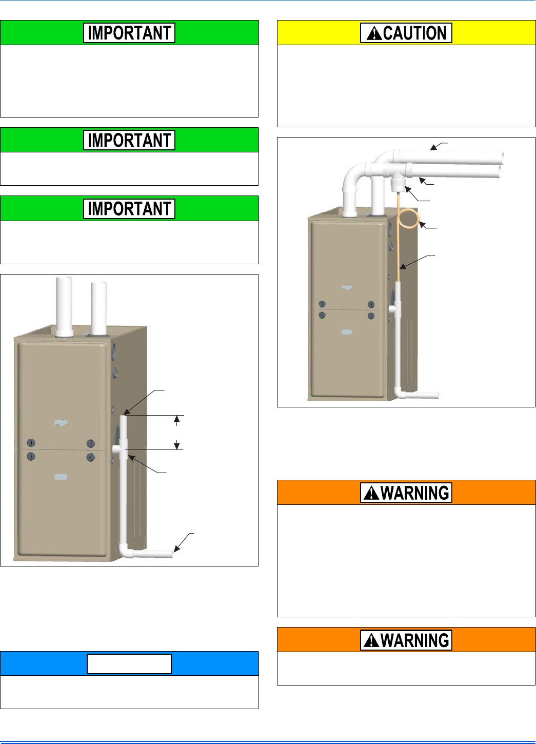
CONDENSATE DRAIN LOCATION
As shipped from the factory:
• For all 040, 060, & 080K input furnaces the main drain is plumbed
through the casing right-side opening when viewed from the front
of the furnace.
• For all 100, 120, & 130K input furnaces the main drain is plumbed
through the casing left-side opening when viewed from the front
of the furnace.
The condensate hoses must slope downwards at all points.
When drain hose routing changes are required (shown in Figures 25 -
28), be sure to cap all un-used openings.
If rerouting hoses - excess length should be cut off so that no sagging
loops will collect and hold condensate - which will cause the furnace to
not operate.
No hose clamps are needed for connecting to the condensate pan.
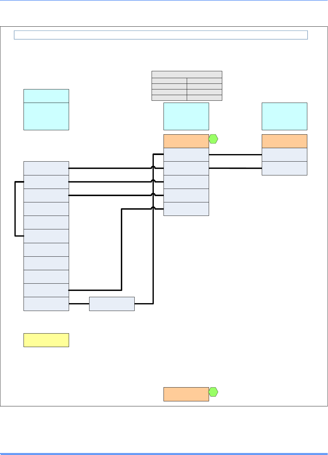
FIGURE 21: Twinning Wiring Diagram
W
G
C
R
Y
TWIN
TO A/C
WALL THERMOSTAT
WG RY
ISOLATION
RELAY
FURNACE 2
CONTROL BOARD
W
G
C
R
Y
TWIN
FURNACE 1
CONTROL BOARD
FIGURE 22: Staging Wiring Diagram
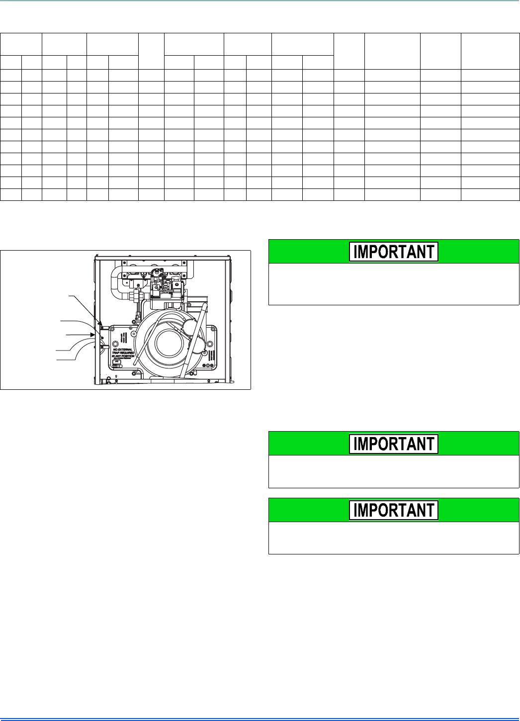
The Figures 25 - 28 show the condensate drain arrangement for the
various possible furnace and vent blower positions.
The furnace condensate pan is self priming and contains an internal
trap to prevent flue gas leaking. Do not install an external condensate
trap.
W
G
C
R
Y
TWIN
TO A/C
WALL THERMOSTAT
W1 G RY
ISOLATION
RELAY
FURNACE 2
CONTROL BOARD
W
G
C
R
Y
TWIN
FURNACE 1
CONTROL BOARD
W2
NOTICE
364861-UIM-H-0712
Johnson Controls Unitary Products 17
The condensate will flow to the drain better if an open stand pipe is
installed in the drain line. See Figure 23.
If evaporator coil or humidifier drains are combined with the furnace
drain, then the open stand pipe could be raised higher, above the 5”
minimum.
CONDENSATE DRAIN TERMINATION
A condensate sump pump MUST be used if required by local codes, or
if no indoor floor drain is available. The condensate sump pump must
be approved for use with acidic condensate.
The furnace, evaporator coil, and humidifier drains may be combined
and drained together. The evaporator coil drain may have an exter-
nal, field-supplied trap prior to the furnace drain connection to prevent
conditioned air leakage. All drain connections (furnace, evaporator
coil, or humidifier) must be terminated into an open or vented drain as
close to the respective equipment as possible. Regular maintenance
is required on condensate drainage system.
Condensate must be disposed of properly. Follow local plumbing
or wastewater codes. The drain line must maintain a 1/4" per foot (20
mm/m) downward slope to the drain.
If an external vent tee is being installed, then it must have its own
condensate trap before it is disposed into an open or vented drain.
This is not to be considered as a second trap as referenced else-
where in this document.
FIGURE 23: Typical. Condensate drain, vertical installation
A loop has been added to the pressure switch vacuum hose. How-
ever, ensure that all pressure switch hoses are routed such that they
prevent any condensate from entering the pressure switch.
To Open Or
Vented Drain
Tee
5” Min.
Open Stand Pipe
(Anti-siphon air vent)
NOTICE
It is possible for condensation to form inside the combustion air
(intake) pipe in the summer months if significant length of combustion
air pipe passes through conditioned space. This problem can be
averted by the addition of a simple drain tee, or a drain tee with a
drain on the combustion air pipe as close to the furnace as possible,
as shown in Figure 24. This is true for all long horizontal venting in
any furnace configuration. This will prevent the condensate from
entering the furnace.
FIGURE 24: Typical. Combustion Pipe Drain Tee
DO NOT terminate the condensate drain in a chimney, or where the
drain line may freeze. If the drain line will be exposed to temperatures
below freezing, adequate measures must be taken to prevent the
drain line from freezing. Failure to provide proper protection from
freezing can result in improper operation or damage to the equipment
and possible property damage. When exposed to temperatures
below freezing, use of a 3 to 6 watt per foot at 115 VAC, 40°F (4.4°C)
self-regulating, shielded and waterproof heat tape is recommended
on the drain line outside the furnace.
DO NOT trap the drain line at any other location than at the conden-
sate drain trap supplied with the furnace.
Liquid anti-freeze will cause damage to internal plastic parts of this
furnace. DO NOT attempt to winterize the furnace using liquid
anti-freeze.
Connect to Drain
Trap
Combustion Air Pipe
Tee with Drain Trap
Exhaust Pipe
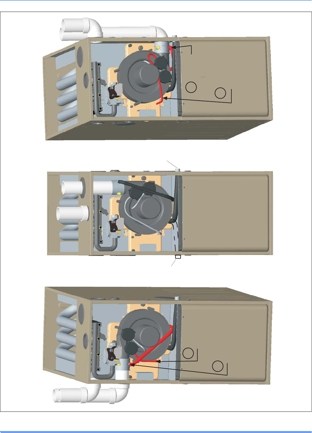
364861-UIM-H-0712
18 Johnson Controls Unitary Products
FIGURE 25: Upflow Configuration
INDUCER ROTATED FOR
LEFT SIDE VENTING
(As required for 130K model)
UPFLOW
AS RECEIVED
(Except for 130K Model)
INDUCER ROTATED FOR
RIGHT SIDE VENTING
When drain hose routing changes are required, be sure to cap all un-used openings.
If rerouting hoses - excess length should be cut off so that no sagging loops will collect
and hold condensate, which will cause the furnace to not operate.
Shorten
pressure
switch hose
Re-route and
shorten
pressure
switch hose
Shorten
rain gutter
hose
Move rain
gutter hose
to this position
For 100, 120 & 130K input furnaces, the condensate
drain is plumbed toward the left casing outlet from the factory.
For 040, 060 & 080K input furnaces, the condensate
drain is plumbed toward the right casing outlet from the factory.
Condensate drain may exit cabinet on either side.
1
2
1
2
130 K Model does not have provisions for top venting, it must be vented through a side opening.
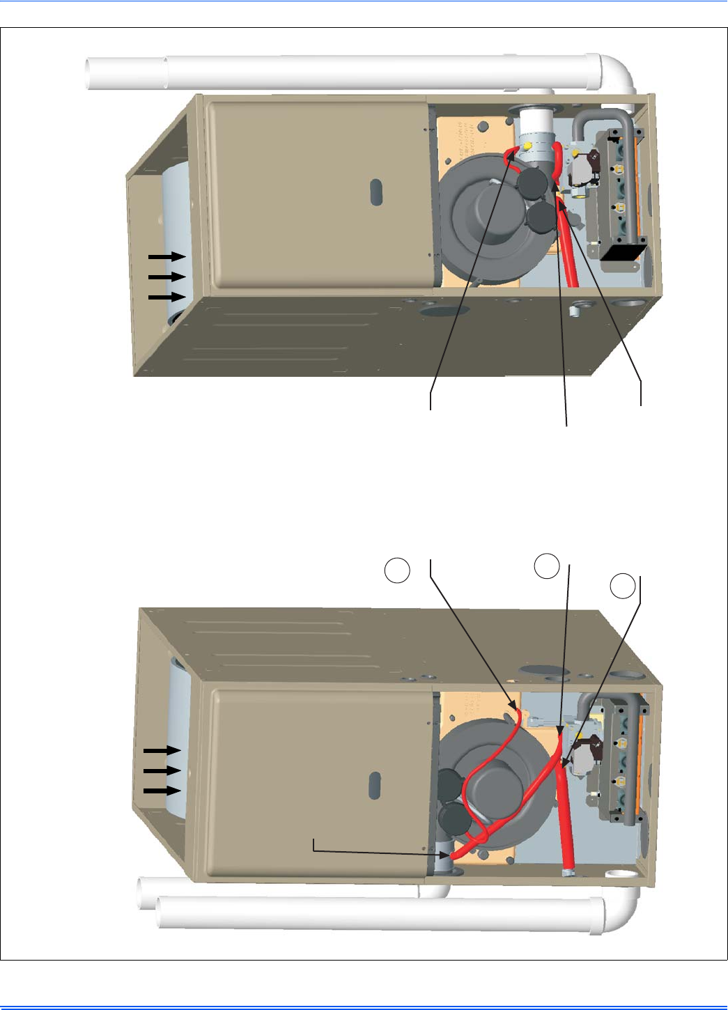
364861-UIM-H-0712
Johnson Controls Unitary Products 19
FIGURE 26: Downflow Configuration
AIRFLOW AIRFLOW
Move rain
gutter hose
to this position
DOWNFLOW - INDUCER ROTATED
FOR LEFT SIDE VENTING
DOWNFLOW - INDUCER ROTATED
FOR RIGHT SIDE VENTING
Move pressure switch
hose to this position.
NOTE: May require
the longer hose that
is provided with
wider cabinets
Move condensate drain
hose to this position
(May exit either side
of the cabinet)
Move rain gutter
hose to this position
When drain hose routing changes are required, be sure to cap all un-used openings.
If rerouting hoses - excess length should be cut off so that no sagging loops will collect
and hold condensate, which will cause the furnace to not operate.
1
2
3
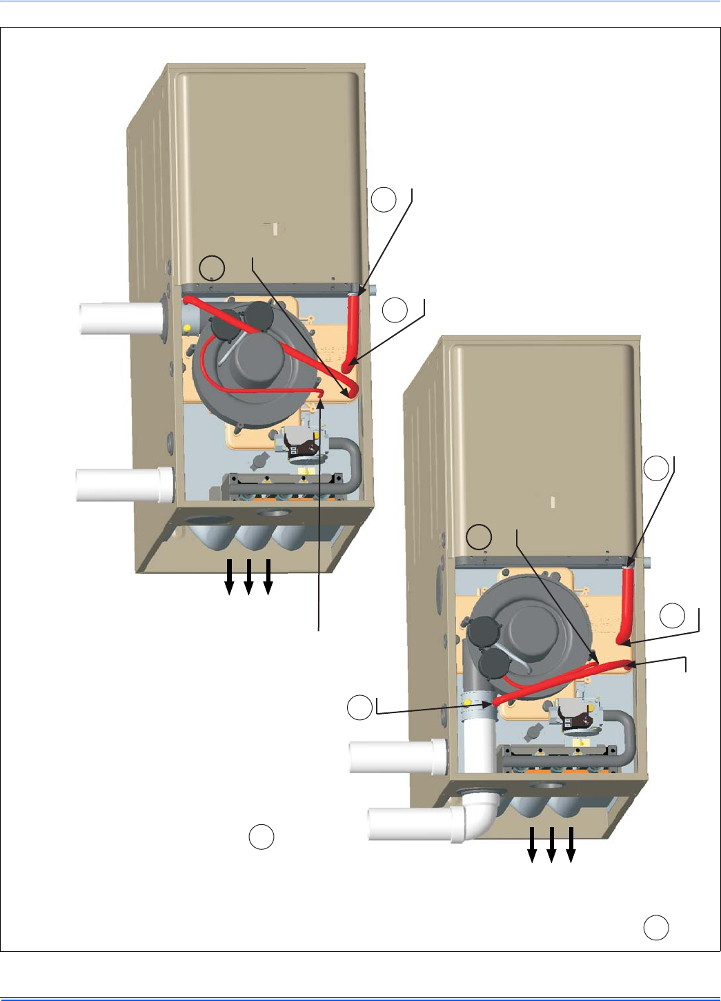
364861-UIM-H-0712
20 Johnson Controls Unitary Products
FIGURE 27: Horizontal Left Configuration
HORIZONTAL - LEFT
INDUCER ROTATED
HORIZONTAL - LEFT
INDUCER AS RECEIVED
(Except for 130K Model)
AIRFLOW
AIRFLOW
Move pressure switch hose
to this position.
NOTE: May require the longer
hose that is provided with
wider cabinets
Move rain gutter hose to this position
NOTE: May require hose extension
that is provided with wider cabinets
Move rain gutter
hose to this position
Move pressure switch
hose to this position.
NOTE: May require
the longer hose that
is provided with
wider cabinets
Change condensate drain
connection to the 90° fitting provided
Move condensate
drain hose to this position
Move rain gutter hose to
this position
NOTE: May require hose
extension that is
provided with wider
cabinets
Move
condensate
drain hose to
this position
Change condensate
drain connection to
the 90° fitting provided
When drain hose routing changes are required, be sure to cap all un-used openings.
If rerouting hoses - excess length should be cut off so that no sagging loops will collect
and hold condensate, which will cause the furnace to not operate.
1
2
3
4
5
34
1
2
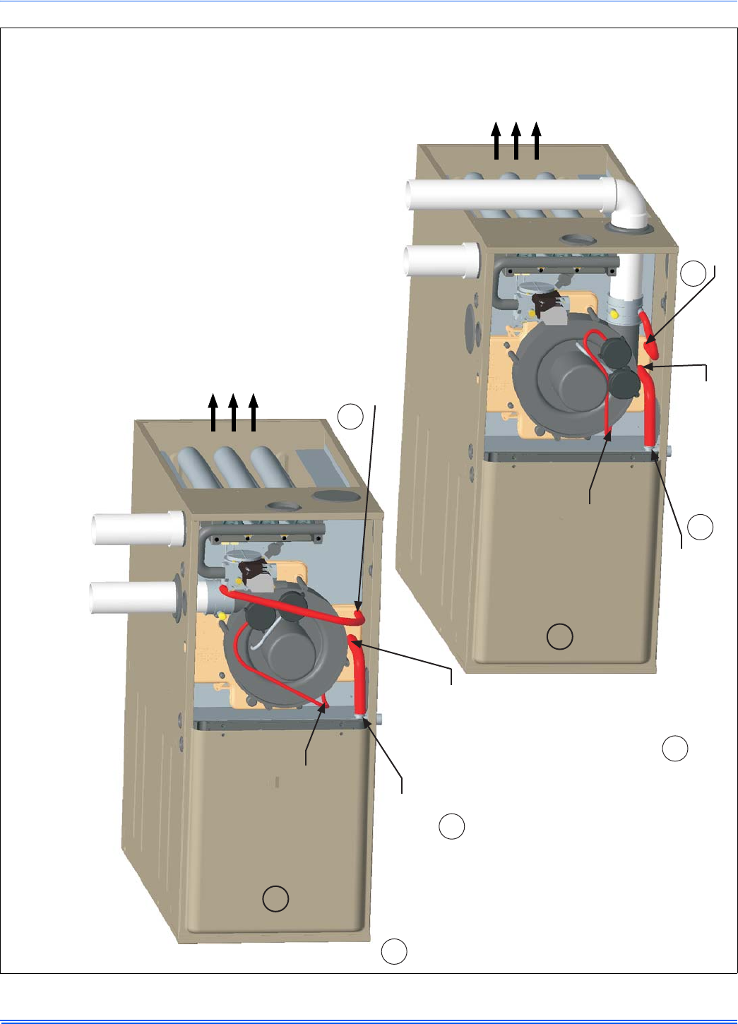
364861-UIM-H-0712
Johnson Controls Unitary Products 21
FIGURE 28: Horizontal Right Configuration
AIRFLOW
HORIZONTAL - RIGHT
INDUCER ROTATED
HORIZONTAL - RIGHT
INDUCER AS RECEIVED
(Except for 130K Model)
Move rain gutter
hose to this position
Move pressure
switch hose to
this position.
Change condensate
drain connection to
the 90° fitting
provided Move condensate
drain hose to
this position
Move rain gutter
hose to this position
Change condensate drain
connection to the 90°
fitting provided Move condensate
drain hose to this position
AIRFLOW
Move pressure
switch hose to
this position.
When drain hose routing changes are required, be sure to cap all un-used openings.
If rerouting hoses - excess length should be cut off so that no sagging loops will collect
and hold condensate, which will cause the furnace to not operate.
2
3
4
1
1
2
34
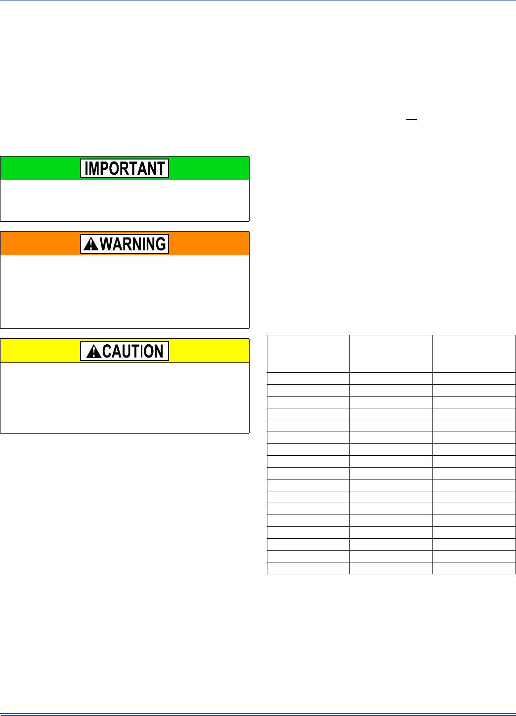
364861-UIM-H-0712
22 Johnson Controls Unitary Products
SECTION VIII: COMBUSTION AIR AND
VENT SYSTEM
COMBUSTION AIR AND VENT SAFETY
This Category IV, dual certified direct vent furnace is designed for resi-
dential application. It may be installed without modification to the con-
densate system in a basement, garage, equipment room, alcove, attic
or any other indoor location where all required clearance to combusti-
bles and other restrictions are met. The combustion air and the venting
system must be installed in accordance with Section 5.3, Air for Com-
bustion and Ventilation, of the National Fuel Gas Code Z223.1/NFPA 54
(latest edition), or Sections 7.2, 7.3 or 7.4 of CSA B149.1, National Gas
and Propane Codes (latest edition) or applicable provisions of the local
building code and these instructions.
COMBUSTION AIR/VENT PIPE SIZING
The size of pipe required will be determined by the furnace model, the
total length of pipe required and the number of elbows required.
Table 7 lists the maximum equivalent length of pipe allowed for each
model of furnace. The equivalent length of elbows is shown in Table 9.
The equivalent length of the vent system is the total length of straight
pipe PLUS the equivalent length of all of the elbows.
The following rules must also be followed:
1. Long radius (sweep) elbows are recommended. Standard elbows
may be used, but since they have a longer equivalent length, they
will reduce the total length of pipe that will be allowed. Short radius
(plumbing vent) elbows are not allowed. The standard dimensions
of the acceptable elbows are shown below.
2. The maximum equivalent length listed in Table 7 is for the vent pip-
ing and the air intake piping separately. For example, if the table
allows 65 equivalent feet for a particular model, then the vent can
have 65 equivalent feet of pipe, AND the combustion air intake can
have another 65 equivalent feet of pipe.
3. Three vent terminal elbows (two for the vent and one for the com-
bustion air intake) are already accounted for and need not be
included in the equivalent length calculation.
4. All combustion air and vent pipe must conform to American
National Standards Institute (ANSI) and American Society for Test-
ing and Materials (ASTM) standards D1785 (Schedule 40 PVC),
D2665 (PVC-DWV), F891 (PVC-DWV Cellular Core), D2261 (ABS-
DWV) or F628 (Schedule 40 ABS). Pipe cement and primer must
conform to ASTM Standard D2546 (PVC) or D2235 (ABS). If ABS
pipe is to be used, any joint where ABS pipe is joined to PVC pipe
must be glued with cement that is approved for use with BOTH
materials. Metallic materials must not be used for venting or air
intake.
5. If a flexible connector is used in the vent system, it must be made of
a material that is resistant to acidic exposure and to at least 225°F
(107°C) temperature. Flexible connectors are also allowed in the
combustion air pipe.
6. All models are supplied with 2" (5.1 cm) vent connections. When
the pipe must be increased to 3" (7.6 cm) diameter, the transition
from 2" to 3" must be done as close to the furnace as possible. For
upflow models, the transition from 2" to 3" should be done immedi-
ately above the furnace. For downflow or horizontal models, the
transition from 2" to 3" pipe should be done immediately after exit-
ing the furnace.
7. In Canada, vents shall be certified to ULC S636, Standard for Type
BH Gas Venting Systems.
8. In Canada, the first three feet (91.4 cm) of the vent must be readily
accessible for inspection.
9. For single pipe systems it is recommended to install the combustion
air coupling provided and install approximately 18” (46 cm) of PVC
pipe on the furnace.
10. Minimum vent length for all models is 5 feet (1.5 m).
The “VENT SYSTEM” must be installed as specified in these instruc-
tions for Residential and non-HUD Modular Homes. The direct vent
system is the only configuration that can be installed in a non-HUD
Modular Home.
This furnace may not be common vented with any other appliance,
since it requires separate, properly sized air intake and vent lines.
The furnace shall not be connected to any type of B, BW or L vent or
vent connector, and not connected to any portion of a factory-built or
masonry chimney
The furnace shall not be connected to a chimney flue serving a sepa-
rate appliance designed to burn solid fuel.
When combustion air pipe is installed above a suspended ceiling or
when it passes through a warm and humid space, the pipe must be
insulated with 1/2” Armaflex or other heat resistant type insulation if
two feet or more of pipe is exposed.
Vent piping must be insulated if it will be subjected to freezing temper-
atures such as routing through unheated areas or through an unused
chimney.
TABLE 7:
Maximum Equivalent Pipe Length
Model Input
BTUH (kW) Pipe Size
Inches (cm)
Maximum
Equivalent
length feet (m)
40,000 2 (5.1) 65 (19.8)
40,000 3 (7.6) 90 (27.4)
40,000 4 (10.2) 150 (45.7)
60,000 2 (5.1) 65 (19.8)
60,000 3 (7.6) 90 (27.4)
60,000 4 (10.2) 150 (45.7)
80,000 2 (5.1) 65 (19.8)
80,000 3 (7.6) 90 (27.4)
80,000 4 (10.2) 150 (45.7)
100,000 2 (5.1) 30 (9.1)
100,000 3 (7.6) 90 (27.4)
100,000 4 (10.2) 150 (45.7)
120,000 2 (5.1) 30 (9.1)
120,000 3 (7.6) 90 (27.4)
120,000 4 (10.2) 150 (45.7)
130,000 3 (7.6) 85 (25.9)
130,000 4 (10.2) 150 (45.7)
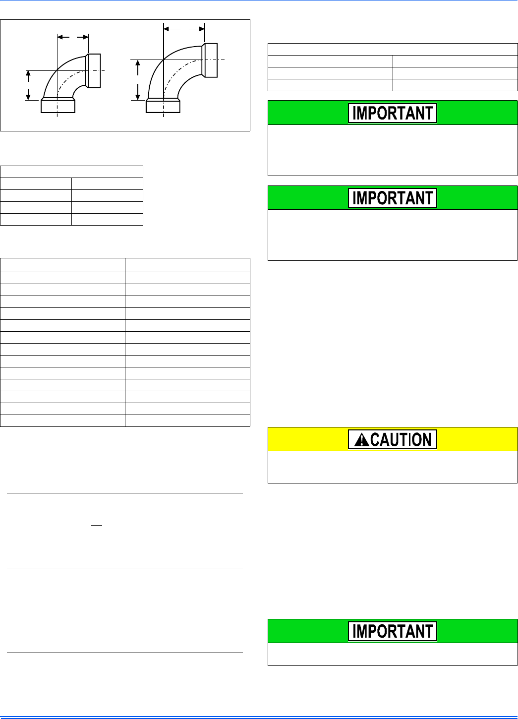
364861-UIM-H-0712
Johnson Controls Unitary Products 23
Dimensions are those required in Standard ASTM D-3311.
Example:
An 80,000 BTUH furnace requires 32 feet of pipe and five 90º elbows.
Using 2" pipe and standard elbows, the total equivalent length will be:
This exceeds the 65 foot maximum equivalent length of 2" pipe allowed
for that model and is thus not acceptable.
By using sweep elbows, the total equivalent length will be:
This is less than the 65 foot maximum equivalent length of 2" pipe
allowed for that model and is thus acceptable.
Alternatively, using 3" pipe and standard elbows, the total equivalent
length will be:
This is less than the 90 foot maximum equivalent length of 3" pipe
allowed for that model and is thus acceptable.
COMBUSTION AIR AND VENT PIPING ASSEMBLY
The final assembly procedure for the combustion air and vent piping is
as follows:
1. Cut piping to the proper length beginning at the furnace.
2. Deburr the piping inside and outside.
3. Chamfer (bevel) the outer edges of the piping.
4. Dry-fit the vent piping assembly from the furnace to the outside ter-
mination checking for proper fit support and slope.
5. Dry-fit the combustion air piping assembly checking for proper fit,
support and slope on the following systems:
a. Sealed combustion air systems from the furnace to the out-
side termination.
b. Ventilated combustion air systems from the furnace to the
attic or crawl space termination.
6. Disassemble the combustion air and vent piping, apply cement
primer and the cement per the manufactures instructions. Primer
and cement must conform to ASTM D2564 for PVC, or ASTM
D2235 for ABS piping.
7. All joints must provide a permanent airtight and watertight seal.
8. Support the combustion air and vent piping such that it is angled a
minimum of 1/4” per foot (21 mm/m) so that condensate will flow
back towards the furnace. Piping should be supported with pipe
hangers to prevent sagging.
9. Seal around the openings where the combustion air and / or vent
piping pass through the roof or sidewalls.
COMBUSTION AIR / VENTING
FIGURE 29:
Dimensions
TABLE 8: Elbow
Dimensions
Elbow "A" Dimension
2" Standard 2-5/16"
3" Standard 3-1/16"
2" Sweep 3-1/4"
3" Sweep 4-1/16"
TABLE 9:
Equivalent Length of Fittings
Fitting Equivalent Length
2" 90° sweep elbow 5 feet of 2" pipe
2" 45° sweep elbow 2-1/2 feet of 2" pipe
2" 90° standard elbow 7 feet of 2" pipe
2" 45° standard elbow 3-1/2 feet of 2" pipe
3" 90° sweep elbow 5 feet of 3" pipe
3" 45° sweep elbow 2-1/2 feet of 3" pipe
3" 90° standard elbow 7 feet of 3" pipe
3" 45° standard elbow 3-1/2 feet of 3" pipe
4" 90° elbow (sweep or standard) 5 feet of 4" pipe
4" 45° elbow (sweep or standard) 2-1/2 feet of 4" pipe
2" corrugated connector 10 feet of 2" pipe
3" corrugated connector 10 feet of 3" pipe
4" corrugated connector 10 feet of 4" pipe
32 feet of 2" pipe = 32 equivalent feet
5 - 90º standard 2" elbows = (5 x 7) = 35 equivalent feet
Total = 67 equivalent feet of 2" pipe
32 feet of 2" pipe = 32 equivalent feet
5 - 90º sweep 2" elbows = (5 x 5) = 25 equivalent feet
Total = 57 equivalent feet of 2" pipe
32 feet of 3" pipe = 32 equivalent feet
5 - 90º standard 3" elbows = (5 x 7) = 35 equivalent feet
Total = 67 equivalent feet of 3" pipe
A
A
A
A
STANDARD ELBOW LONG (SWEEP) ELBOW
TABLE 10:
Combustion Air Intake and Vent Connection Size at Furnace
(All Models)
FURNACE VENT CONNECTION SIZES
Furnace Input All
Intake Pipe Size 2” (5.1 cm)
Vent Pipe Size 2” (5.1 cm)
Furnace vent pipe connections are sized for 2” (5.1 cm). pipe. Any
pipe size change must be made outside the furnace casing in a verti-
cal pipe section to allow proper drainage of condensate. An offset
using two 45º (degree) elbows will be required for plenum clearance
when the vent is increased to 3” (7.6 cm).
Accessory concentric vent / intake termination kits 1CT0302 and
1CT0303, and for Canadian applications 1CT0302-636 and
1CT0303-636 are available and approved for use with these fur-
naces. Horizontal sidewall vent terminations kits 1HT0901 &
1HT0902 are also approved for use with these furnaces.
Solvent cements are flammable and must be used in well-ventilated
areas only. Keep them away from heat, sparks and open flames. Do
not breathe vapors and avoid contact with skin and eyes.
The vent must be installed with the minimum required clearances,
and must comply with local codes and requirements.

364861-UIM-H-0712
24 Johnson Controls Unitary Products
VENT CLEARANCES
† A vent shall not terminate directly above a sidewalk or paved driveway that is located between two single family dwellings and serves both dwellings.
†† 12” (30.5 cm) up from the bottom edge of the structure for Two-pipe (direct vent) applications per ANSI Z223.1 / NFPA 54, National Gas Code.
‡ Permitted only if veranda, porch, deck, or balcony is fully open on a minimum of two sides beneath the floor and the distance between the top of the vent termina-
tion and the underside of the veranda, porch, or deck is greater than 12” (30.5 cm) as specified in CSA B149.1-00.
A vent shall not terminate less than 12” (30.5 cm) above a grade level.
Any fresh air or make up inlet for dryer or furnace area is considered to be forced air inlet.
Avoid areas where condensate drippage may cause problems such as above planters, patios, or adjacent to windows where steam may cause fogging.
A terminus of a vent shall be fitted with a cap in accordance with the vent manufacturer’s installation instructions, or in accordance with the installation instructions for a
special venting system.
Responsibility for the provision of proper adequate venting and air supply for application shall rest with the installer.
Vent shall extend high enough above building, or a neighboring obstruction, so that wind from any direction will not create a positive pressure in the vicinity of the vent.
FIGURE 30: Home Layout
L
E
D
B
V
V
VX
V
B
V
J
X
B
B
B
V
V
F
V
C
B
X
V
I
V
G
H
A
M
K
OPERABLE
FIXED
CLOSED
VENT TERMINAL
AIR SUPPLY
AREA WHERE TERMINAL IS NOT PERMITTED
FIXED
CLOSED
Direct Vent Terminal Clearances Canadian Installations1,3 US Installation2,3
A. Clearance above grade, veranda, porch, deck, or
balcony 12” (30.5 cm) 12” (30.5 cm)
B. Clearance to window or door that may be opened 12” (30.5 cm) for models 100,000 BTUH (30 kW),
36” (91.4 cm) for models >100,000 BTUH (30 kW). Two-pipe (direct vent) applications: 12” (30.5 cm)††
Single-pipe applications: 4 feet (1.2 m).
C. Clearance to permanently closed window 12” (30.5 cm) 12” (30.5 cm)
D. Vertical clearance to ventilated soffit located
above the terminal within a horizontal distance
of 2 feet (61 cm) from the center line of the terminal
12” (30.5 cm) or in accordance with local installation
codes and the requirements of the gas supplier. 12” (30.5 cm) or in accordance with local installation
codes and the requirements of the gas supplier.
E. Clearance to unventilated soffit 12” (30.5 cm) or in accordance with local installation
codes and the requirements of the gas supplier. 12” (30.5 cm) or in accordance with local installation
codes and the requirements of the gas supplier.
F. Clearance to outside corner 12” (30.5 cm) or in accordance with local installation
codes and the requirements of the gas supplier. 12” (30.5 cm) or in accordance with local installation
codes and the requirements of the gas supplier.
G. Clearance to inside corner 3 feet (91.4 cm) 3 feet (91.4 cm)
H. Clearance to each side of center line
extended above meter/regulator assembly
Above a meter/regulator assembly within 3 feet
(91.4 cm) horizontally of the vertical center-line of the
regulator vent outlet to a maximum vertical distance of
15 feet (4.5 m) above the meter/regulator assembly.
Above a meter/regulator assembly within 3 feet
(91 cm) horizontally of the vertical center-line of the
regulator vent outlet to a maximum vertical distance of
15 feet (4.5 m) above the meter/regulator assembly.
I. Clearance to service regulator vent outlet 3 feet (91.4 cm) 3 feet (91.4 cm) or in accordance with local installation
codes and the requirements of the gas supplier.
J. Clearance to non-mechanical air supply inlet to
building or the combustion air inlet to any other
appliance
12” (30.5 cm) for models 100,000 BTUH (30 kW),
36” (91 cm) for models >100,000 BTUH (30 kW). Two-pipe (direct vent) applications: 12” (30.5 cm)
Single-pipe applications: 4 feet (1.2 m).
K. Clearance to a mechanical supply inlet 6 feet (1.83 m) 3 feet (91.4 cm) above if within 10 feet (3 m)
horizontally.
L. Clearance above paved sidewalk or paved
driveway located on public property 7 feet (2.13 m)† 7 feet (2.13 m) or in accordance with local installation
codes and the requirements of the gas supplier.
M. Clearance under veranda, porch, deck, or balcony 12” (30.5 cm)‡ 12” (30.5 cm) or in accordance with local installation
codes and the requirements of the gas supplier.
1. In accordance with the current CSA B149.1-00, Natural Gas and Propane Installation Code.
2. In accordance with the current ANSI Z223.1 / NFPA 54, National Gas Code.
3. In accordance with the current ANSI Z21.47 * CSA 2.3 American National Standard.
Consideration must be given for degradation of building materials by flue gases. Sidewall termination may require sealing or shielding of building
surfaces with a corrosion resistant material to protect against combustion product corrosion. Consideration must be given to wind direction in order
to prevent flue products and/or condensate from being blown against the building surfaces. If a metal shield is used it must be a stainless steel
material at a minimum dimension of 20 inches (51 cm). It is recommended that a retaining type collar be used that is attached to the building sur-
face to prevent movement of the vent pipe.
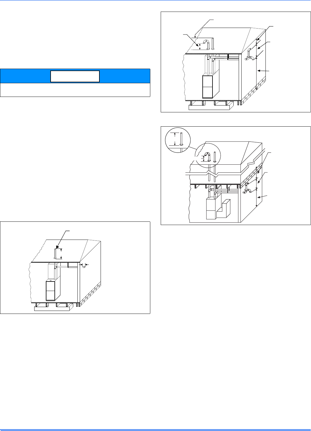
364861-UIM-H-0712
Johnson Controls Unitary Products 25
VENT SYSTEM
This furnace is certified to be installed with one of two possible vent
configurations.
1. Horizontal vent system. This vent system can be installed com-
pletely horizontal or combinations of horizontal, vertical, or offset
using elbows.
2. Vertical vent system. This vent system can be installed completely
vertical or a combination of horizontal, vertical, or offset using
elbows.
VENT APPLICATIONS AND TERMINATION
When selecting the location for a combustion air / vent termination, the
following should be considered:
1. Observe all clearances listed in vent clearances in these instruc-
tions.
2. Termination should be positioned where vent vapors will not dam-
age plants or shrubs or air conditioning equipment.
3. Termination should be located where it will not be affected by wind
gusts, light snow, airborne leaves or allow recirculation of flue
gases.
4. Termination should be located where it will not be damaged or
exposed to flying stones, balls, etc.
5. Termination should be positioned where vent vapors are not objec-
tionable.
6. Horizontal portions of the vent system must slope upwards and be
supported to prevent sagging.
7. Direct vent systems must be installed so the vent and the combus-
tion air pipes terminate in the same atmospheric zone. Refer to Fig-
ures 32 or 33.
VENTING MULTIPLE UNITS
Multiple units can be installed in a space or structure as either a single
pipe configuration or a two-pipe configuration.
The combustion air side of the single pipe configuration shown in Figure
31 is referred to in these instructions as ambient combustion air supply.
Follow the instructions for ambient combustion air installations, paying
particular attention to the section on air source from inside the building.
The vent for a single pipe system must be installed as specified in the
venting section of these instructions with the vent terminating as shown
in Figure 31. Each furnace must have a separate vent pipe. Under NO
circumstances can the two vent pipes be tied together.
The combustion air side of the two-pipe configuration shown in Figure
32 can be installed so the combustion air pipe terminates as described
in outdoor combustion air or ventilated combustion air sections in these
instructions. Follow the instructions for outdoor combustion air or venti-
lated combustion air and the instructions for installing the vent system
with the vent terminating as shown in Figures 34 or 35. The two-pipe
system must have a separate combustion air pipe and a separate vent
pipe for each furnace. Under NO circumstances can the two combus-
tion air or vent pipes be tied together. The combustion air and vent
pipes must terminate in the same atmospheric zone.
On 130K BTU models, there is no provision for the vent to exit
the top of the cabinet, the vent must always exit one of the sides.
FIGURE 31: Termination Configuration - 1 Pipe
NOTICE
12” Min.
12” Min.
Maintain 12” minimum clearance
above highest anticipated snow level.
Maximum 24” above roof.
FIGURE 32: Termination Configuration - 2 Pipe
FIGURE 33: Termination Configuration - 2 Pipe Basement
Maintain 12” minimum
clearance above
highest anticipated
snow level.
12” vertical separation
between combustion air
intake and vent. 12” minimum
below overhang
12” minimum
separation between
bottom of
combustion air pipe
and bottom of vent.
Maintain 12”
minimum clearance
above highest
anticipated snow
level or grade,
whichever is higher.
12” MIN.
12” MIN.
OVERHANG
12” Minimum
below overhang
12” Minimum
separation between
bottom of
combustion air
intake and
bottom of vent
Maintain 12”
minimumclearance
above highest
anticipated snow
level or grade,
whichever is higher

364861-UIM-H-0712
26 Johnson Controls Unitary Products
DOWNWARD VENTING
In some applications, it may be necessary to run the vent pipe and air
intake downwards. If this is to be done, the following rules must be fol-
lowed.
• A condensate trap hose must be connected to both the air intake
pipe and the vent pipe at the lowest part of the horizontal run.
• The condensate drain trap must have a trap of a minimum of six
inches.
• The total vertical downward distance must not exceed sixteen
feet.
• The condensate drain hose must be connected to a condensate
drain pump, a open or vented drain or into the condensate drain
line from the furnace.
• The condensate drain lines must not pass through unconditioned
spaces where the temperature may fall below freezing.
• The condensate drain line must be primed at the initial start-up
prior to the start of heating season.
COMBUSTION AIR SUPPLY
All installations must comply with Section 5.3, Air for Combustion and
Ventilation of the National Fuel Gas Code, ANSI Z223.1 or Sections
7.2, 7.3 or 7.4 of CAN/CGA B149.1 or .2 Installation Code - latest edi-
tions.
This furnace is certified to be installed with one of three possible com-
bustion air intake configurations.
1. OUTDOOR COMBUSTION AIR: This is a direct vent configuration
where the combustion air is supplied through a PVC or ABS pipe
that is connected to the PVC coupling attached to the furnace and
is terminated in the same atmospheric zone as the vent. This type
of installation is approved on all models. Refer to Figure 36.
2. AMBIENT COMBUSTION AIR: Combustion air is supplied from
the area surrounding the furnace through openings in the furnace
casing. The combustion air and the vent pipes are not terminated in
the same atmospheric zone. Refer to Figure 31 for vent termina-
tions. Refer to "Ambient Combustion Air Supply" for proper installa-
tion. Refer to Figure 27.
3. VENTILATED COMBUSTION AIR: Combustion air is supplied
through a PVC or ABS pipe that is connected to the PVC coupling
attached to the burner box and is terminated in a ventilated attic or
crawl space. The combustion air and the vent pipes are not termi-
nated in the same atmospheric zone. Refer to Figure 39 for attic
and crawl space termination. Only the combustion air intake may
terminate in the attic. The vent must terminate outside.
Outdoor Combustion Air
Combustion Air Intake/Vent Connections
This installation requires combustion air to be brought in from outdoors.
This requires a properly sized pipe (Shown in Figure 36) that will bring
air in from the outdoors to the furnace combustion air intake collar on
the burner box. The second pipe (Shown in Figure 36) is the furnace
vent pipe.
The combustion air intake pipe should be located either through the
wall (horizontal or side vent) or through the roof (vertical vent). Care
should be taken to locate side vented systems where trees or shrubs
will not block or restrict supply air from entering the terminal.
Also, the terminal assembly should be located as far as possible from a
swimming pool or a location where swimming pool chemicals might be
stored. Be sure the terminal assembly follows the outdoor clearances
listed in Section #1 “Outdoor Air Contaminants.”
FIGURE 34: Double Horizontal Combustion Air Intake and Vent
Termination
FIGURE 35: Double Vertical Combustion Air Intake and Vent
Termination
FIGURE 36: Downward Venting
VENT
2”
MIN.
COMBUSTION AIR
MIN.
6”
16’ MAX
6” MIN.
6” MIN.
An optional plastic birdscreen is shipped in the loose parts bag with
every furnace. This may be installed in the intake collar to prevent any
small objects from entering the furnace.
FIGURE 37: Direct Vent Air Intake Connection and Vent Connection
NOTICE
Connects to
collar on top
of burner box
Vent pipe cements
into socket just
above top panel
Or vent pipe may be
clamped into outlet
of drain coupling
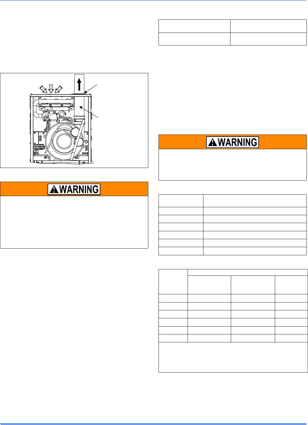
364861-UIM-H-0712
Johnson Controls Unitary Products 27
Ambient Combustion Air Supply
This type installation will draw the air required for combustion from
within the space surrounding the appliance and from areas or rooms
adjacent to the space surrounding the appliance. This may be from
within the space in a non-confined location or it may be brought into the
furnace area from outdoors through permanent openings or ducts. It is
not piped directly into the furnace. A single, properly sized pipe from the
furnace vent connector to the outdoors must be provided. It is recom-
mended that the supplied intake coupling & 18” of pipe be attached to
the furnace to prevent accidental blockage of the combustion air intake.
An unconfined space is not less than 50 cu.ft (1.42 m3) per 1,000 Btu/
hr (0.293 kW/h) input rating for all of the appliances installed in that
area.
Rooms communicating directly with the space containing the appli-
ances are considered part of the unconfined space, if doors are fur-
nished with openings or louvers.
A confined space is an area with less than 50 cu.ft (1.42 m3) per 1,000
Btu/hr (0.293 kW/h) input rating for all of the appliances installed in that
area. The following must be considered to obtain proper air for combus-
tion and ventilation in confined spaces.
Combustion Air Source From Outdoors
The blocking effects of louvers, grilles and screens must be given con-
sideration in calculating free area. If the free area of a specific louver or
grille is not known, Refer to Table11, to estimate free area.
* Do not use less than 1/4” (6.4 mm) mesh
+ Free area of louvers and grille varies widely; the installer should follow
louver or grille manufacturer’s instructions.
Dampers, Louvers and Grilles (Canada Only)
1. The free area of a supply air opening shall be calculated by sub-
tracting the blockage area of all fixed louvers grilles or screens from
the gross area of the opening.
2. Apertures in a fixed louver, a grille, or screen shall have no dimen-
sion smaller than 1/4” (6.4 mm).
3. A manually operated damper or manually adjustable louvers are
not permitted for use.
4. A automatically operated damper or automatically adjustable lou-
vers shall be interlocked so that the main burner cannot operate
unless either the damper or the louver is in the fully open position.
FIGURE 38: Combustion Airflow Path Through The Furnace Casing
This type of installation requires that the supply air to the appliance(s)
be of a sufficient amount to support all of the appliance(s) in the area.
Operation of a mechanical exhaust, such as an exhaust fan, kitchen
ventilation system, clothes dryer or fireplace may create conditions
requiring special attention to avoid unsatisfactory operation of gas
appliances. A venting problem or a lack of supply air will result in a
hazardous condition, which can cause the appliance to soot and gen-
erate dangerous levels of CARBON MONOXIDE, which can lead to
serious injury, property damage and / or death.
Vent pipe cements
into socket just
above top panel
COMBUSTION AIR
Or vent pipe may be
clamped into outlet
of drain coupling
Table 11: Estimated Free Area
Wood or Metal
Louvers or Grilles
Wood 20-25%*
Metal 60-70% *
Screens+ 1/4” (6.4 mm)
mesh or larger 100%
When a Category I furnace is removed or replaced, the original vent-
ing system may no longer be correctly sized to properly vent the
attached appliances.
An improperly sized vent system can cause CARBON MONOXIDE to
spill into the living space causing personal injury, and or death.
Table 12: Unconfined Space Minimum Area
BTUH Input Rating Minimum Free Area
Required for Each Opening
40,000 40 in2 (258 cm2)
60,000 60 in2 (387 cm2)
80,000 80 in2 (516 cm2)
100,000 100 in2 (645 cm2)
120,000 120 in2 (742 cm2)
130,000 130 in2 (838 cm2)
Table 13: Free Area
BTUH Input
Rating
Minimum Free Area Required for Each Opening
Horizontal Duct
(2,000 BTUH)
Vertical Duct or
Opening to Outside
(4,000 BTUH)
Round Duct
(4,000 BTUH)
40,000 20 in2 (129 cm2) 10 in2 (64 cm2)4” (10 cm)
60,000 30 in2 (193 cm2) 15 in2 (97 cm2)5” (13 cm)
80,000 40 in2 (258 cm2) 20 in2 (129 cm2)5” (13 cm)
100,000 50 in2 (322 cm2) 25 in2 (161 cm2)6” (15 cm)
120,000 60 in2 (387 cm2) 30 in2 (193 cm2)7” (18 cm)
130,000 65 in2 (419 cm2) 33 in2 (213 cm2)7” (18 cm)
EXAMPLE: Determining Free Area.
Appliance 1 Appliance 2 Total Input
100,000 + 30,000 = (130,000 4,000) = 32.5 Sq. In. Vertical
Appliance 1 Appliance 2 Total Input
100,000 + 30,000 = (130,000 2,000) = 65 Sq. In. Horizontal
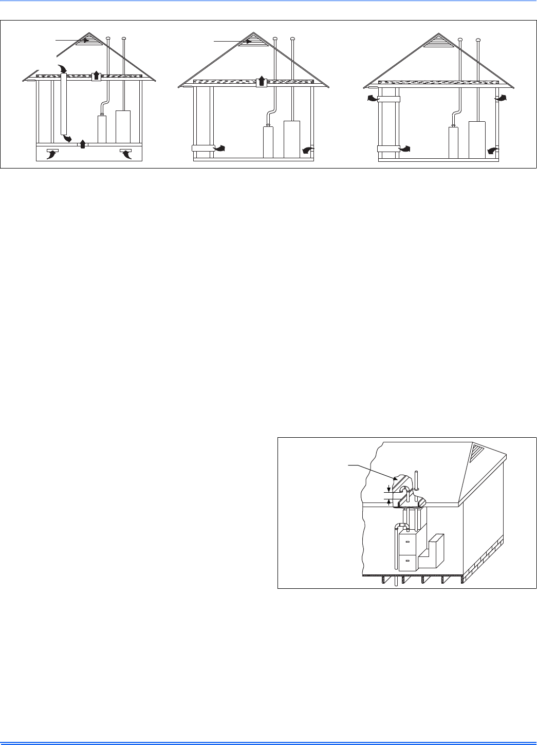
364861-UIM-H-0712
28 Johnson Controls Unitary Products
Air Supply Openings and Ducts
1. An opening may be used in lieu of a duct to provide to provide the
outside air supply to an appliance unless otherwise permitted by
the authority having jurisdiction. The opening shall be located within
12” (30.5 cm) horizontally from, the burner level of the appliance.
Refer to “AIR SOURCE FROM OUTDOORS AND VENT AND
SUPPLY AIR SAFETY CHECK” in these instructions for additional
information and safety check procedure.
2. The duct shall be either metal, or a material meeting the class 1
requirements of CAN4-S110 Standard for Air Ducts.
3. The duct shall be least the same cross-sectional area as the free
area of the air supply inlet opening to which it connects.
4. The duct shall terminate within 12” (30.5 cm) above, and within
24” (61 cm) horizontally from, the burner level of the appliance hav-
ing the largest input.
5. A square or rectangular shaped duct shall only be used when the
required free area of the supply opening is 9 in2 (58.06 cm2) or
larger. When a square or rectangular duct is used, its small dimen-
sion shall not be less than 3” (7.6 cm).
6. An air inlet supply from outdoors shall be equipped with a means to
prevent the direct entry of rain and wind. Such means shall not
reduce the required free area of the air supply opening.
7. An air supply inlet opening from the outdoors shall be located not
less than 12” (30.5 cm) above the outside grade level.
Combustion Air Source from Outdoors
1. Two permanent openings, one within 12” (30.5 cm) of the top and
one within 12” (30.5 cm) of bottom of the confined space, Two per-
manent openings, shall communicate directly or by means of ducts
with the outdoors, crawl spaces or attic spaces.
2. One permanent openings, commencing within 12” (30.5 cm) of the
top of the enclosure shall be permitted where the equipment has
clearances of at least 1” (2.54 cm) from the sides and back and 6”
(15.2 cm) from the front of the appliance. The opening shall com-
municate directly with the outdoors and shall have a minimum free
area of:
a. 1 square inch per 3000 BTU per hour (322 cm2 per 0.879
kW) of the total input rating of all equipment located in the
enclosure.
b. Not less than the sum of all vent connectors in the confined
space.
3. The duct shall be least the same cross-sectional area as the free
area of the air supply inlet opening to which it connects.
4. The blocking effects of louvers, grilles and screens must be given
consideration in calculating free area. If the free area of a specific
louver or grille is not known. Refer to Table 11.
Ventilated Combustion Air
The ventilated attic space or a crawl space from which the combustion
air is taken must comply with the requirements specified in “AIR
SOURCE FROM OUTDOORS” in this instruction or in Section 5.3, Air
for Combustion and Ventilation of the National Fuel Gas Code, ANSI
Z223.1 (latest edition). This type installation requires two properly sized
pipes. One brings combustion air from a properly ventilated attic space
or crawl space and a second pipe that extends from the furnace vent
connection (top right of unit) to the exterior of the building. Refer to
Table 7 for intake pipe sizing, allowable length and elbow usage. Follow
all notes, procedures and required materials in the "COMBUSTION
AIR/VENT PIPE SIZING" section in these instructions when installing
the combustion air pipe from the unit and into a ventilated attic space or
crawl space. DO NOT terminate vent pipe in an Attic or Crawl Space.
Ventilated Combustion Air Termination
Refer to Figure 39 for required attic termination for the combustion air
intake pipe. For attic termination, use two 90 elbows with the open end
in a downward position. Be sure to maintain 12” (30.5 cm) clearance
above any insulation, flooring or other material.
A crawl space combustion air installation consists of a straight pipe from
the PVC coupling on the burner box that extends into the crawl space
and terminates with a 1/4” (6.4 mm) mesh screen and no elbows.
FIGURE 39: Outside and Ambient Combustion Air
Gable
Vent
Gas
Vent
Soffit
Vent
Ventilated
Attic
Top Above
Insulation
Optional
Inlet (a)
Outlet
Air (a)
Ventilated
Crawl Space
Gas
Water
Heater
Furnace
Soffit
Vent
Gas
Water
Heater Inlet
Air (a)
Inlet
Air (b)
Furnace
Gas
Vent
Outlet
Air (a)
Outlet
Air (b)
Inlet
Air (a)
Inlet
Air (b)
Gas
Water
Heater
Furnace
Ventilated
Attic
Top Above
Insulation
Gable
Vent
Gas
Vent
FIGURE 40: Attic and Crawl Space Combustion Air Termination
12” Min.
12” minimum
between bottom
of air intake and
any material below.
364861-UIM-H-0712
Johnson Controls Unitary Products 29
Specially Engineered Installations
The above requirements shall be permitted to be waived where special
engineering, approved by the authority having jurisdiction, provides an
adequate supply of air for combustion and ventilation.
VENT BLOWER ROTATION
For ease of venting, the vent blower may be rotated 90° in either direc-
tion. For upflow installations the vent may exit through the top or either
side of the cabinet. For downflow installations, the vent blower must be
rotated so that the vent exits through either side of the cabinet. See Fig-
ures 25-28 for details.
SECTION IX: START-UP AND
ADJUSTMENTS
The initial start-up of the furnace requires the following additional
procedures:
When the gas supply is initially connected to the furnace, the gas piping
may be full of air. In order to purge this air, it is recommended that the
ground union be loosened until the odor of gas is detected. When gas is
detected, immediately retighten the union and check for leaks. Allow
five minutes for any gas to dissipate before continuing with the start-up
procedure. Be sure proper ventilation is available to dilute and carry
away any vented gas.
GAS PIPING LEAK CHECK
It is recommended that when the gas supply is first connected to the
furnace, the ground union be loosened until the odor of gas is detected.
When gas is detected, immediately tighten the union and check for gas
leaks. Allow five minutes for any gas to dissipate before continuing with
the startup procedure. Be sure that proper ventilation is available to
dilute and carry away any vented gas.
With furnace in operation, check all of the pipe joints, gas valve connec-
tions and manual valve connections for leakage using an approved gas
detector, a non-corrosive leak detection fluid or other leak detection
methods. Take appropriate action to stop any leak. If a leak persists,
replace the faulty component.
The furnace and its equipment shutoff valve must be disconnected from
the gas supply during any pressure testing of that system at test pres-
sures in excess of 0.5 psig (3.45 kPa).
The furnace must be isolated from the gas supply piping system by
closing the equipment shutoff valve during any pressure testing of the
gas supply system.
CARBON MONOXIDE POISONING HAZARD
Failure to follow the steps outlined below for each appliance connected to the venting system being placed into operation could result in carbon-
monxide poisoning or death.
The following steps shall be followed for each appliance connected to the venting system being placed into operation, while all other appliances
connected to the venting system are not in operation:
1. Inspect the venting system for proper size and horizontal pitch. Determine that there is no blockage, restriction, leakage, corrosion or other
deficiencies, which could cause an unsafe condition.
2. Close all building doors and windows and all doors.
3. Turn on clothes dryers and TURN ON any exhaust fans, such as range hoods and bathroom exhausts, so they shall operate at maximum
speed. Open the fireplace dampers. Do not operate a summer exhaust fan.
4. Follow the lighting instructions. Place the appliance being inspected in operation. Adjust thermostat so the appliance shall operate contin-
uously.
5. Test each appliance (such as a water heater) equipped with a draft hood for spillage (down-draft or no draft) at the draft hood relief opening
after 5 minutes of main burner operation. Appliances that do not have draft hoods need to be checked at the vent pipe as close to the
appliance as possible. Use a combustion analyzer to check the CO2 and CO levels of each appliance. Use a draft gauge to check for a
downdraft or inadequate draft condition.
6. After it has been determined that each appliance properly vents when tested as outlined above, return doors, windows, exhaust fans, fire-
place dampers and any other gas burning appliance to their normal condition.
7. If improper venting is observed during any of the above tests, a problem exists with either the venting system or the appliance does not
have enough combustion air (Supply Air from outside) to complete combustion. This condition must be corrected before the appliance can
function safely.
NOTE: An unsafe condition exists when the CO reading exceeds 40 ppm and the draft reading is not in excess of - 0.1” w.c. (-25 kPa) with all
of the appliance(s) operating at the same time.
8. Any corrections to the venting system and / or to the supply (outside) air system must be in accordance with the National Fuel Gas Code
Z223.1 or CAN/CGA B149.1 Natural Gas and Propane Installation Code (latest editions). If the vent system must be resized, follow the
appropriate tables in Appendix G of the above codes or for this appliance.
Be sure to instruct the owner not to block this intake pipe.
All electrical connections made in the field and in the factory should
be checked for proper tightness.
FIRE OR EXPLOSION HAZARD
Failure to follow the safety warnings exactly could result in serious
injury, death or property damage.
Never test for gas leaks with an open flame. Use a commercially
available soap solution made specifically for the detection of leaks to
check all connections. A fire or explosion may result causing property
damage, personal injury or loss of life.
Burner ignition may not be satisfactory on first startup due to residual
air in the gas line or until gas manifold pressure is adjusted. The igni-
tion control will make three attempts to light before locking out.
364861-UIM-H-0712
30 Johnson Controls Unitary Products
IGNITION SYSTEM SEQUENCE
1. Turn the gas supply ON at external valve and main gas valve.
2. Set the thermostat above room temperature to call for heat.
3. System start-up will occur as follows:
a. The induced draft blower motor will start and come up to
speed. Shortly after inducer start-up, the hot surface igniter
will glow for about 17 seconds.
b. After this warm up, the ignition module will energize (open)
the main gas valve.
c. After flame is established, the supply air blower will start in
about 30 seconds.
CALCULATING THE FURNACE INPUT (NAT. GAS)
Burner orifices are sized to provide proper input rate using natural gas
with a heating value of 1030 BTU/Ft3 (38.4 MJ/m3). If the heating value
of your gas is significantly different, it may be necessary to replace the
orifices.
Verify natural gas input rate by clocking meter.
1. Turn off all other gas appliances and pilots.
2. Run furnace for a minimum of 3 minutes in heating operation.
3. Measure time (in sec) for gas meter to complete 1 revolution and
note reading. The 2 cubic feet dial provides a more accurate mea-
surement of gas flow.
4. Refer to Table 14 for cubic feet of gas per hour.
5. Multiply cubic feet per hour by heating valve (BTU/cu ft) to obtain
input.
If clocked rate does not match the input rate from the unit nameplate.
follow steps in next section to adjust the manifold pressure. Repeat
steps 2 - 5 until correct input is achieved.
HOT SURFACE IGNITION SYSTEM
Do not attempt to light this furnace by hand (with a match or any
other means). There may be a potential shock hazard from the
components of the hot surface ignition system. The furnace can
only be lit automatically by its hot surface ignition system.
DO NOT set manifold pressure less than 3.2” w.c. or more than 3.8”
w.c. for natural gas at sea level. If manifold pressure is outside this
range, change main burner orifices.
NOTICE
If orifice hole appears damaged or it is suspected to have been
redrilled, check orifice hole with a numbered drill bit of correct size.
Never redrill an orifice. A burr-free and squarely aligned orifice hole is
essential for proper flame characteristics.
DO NOT bottom out gas valve regulator adjusting screw. This can
result in unregulated manifold pressure and result in excess overfire
and heat exchanger failures.
Be sure to relight any gas appliances that were turned off at the start
of this input check.
NOTICE
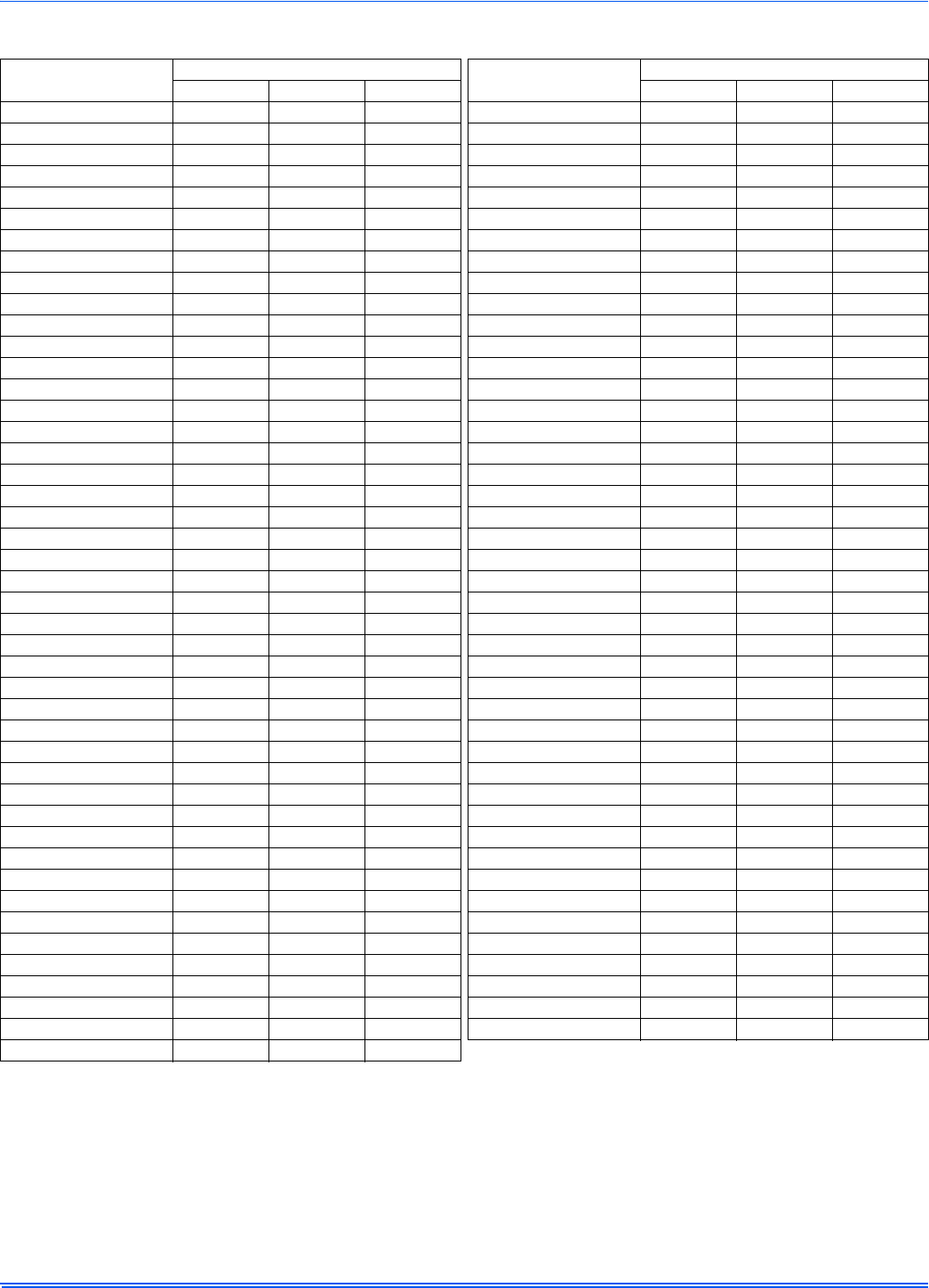
364861-UIM-H-0712
Johnson Controls Unitary Products 31
Table 14: Gas Rate (CU FT/HR) at Full Input
Seconds For
1 Revolution
Size of Test Dial Seconds For
1 Revolution
Size of Test Dial
1 Cu Ft 2 Cu Ft 5 Cu Ft 1 Cu Ft 2 Cu Ft 5 Cu Ft
10 360 720 1800 55 65 131 327
11 327 655 1636 56 64 129 321
12 300 600 1500 57 63 126 316
13 277 555 1385 58 62 124 310
14 257 514 1286 59 61 122 305
15 240 480 1200 60 60 120 300
16 225 450 1125 62 58 116 290
17 212 424 1059 64 56 112 281
18 200 400 1000 66 54 109 273
19 189 379 947 68 53 106 265
20 180 360 900 70 51 103 257
21 171 343 857 72 50 100 250
22 164 327 818 74 48 97 243
23 157 313 783 76 47 95 237
24 150 300 750 78 46 92 231
25 144 288 720 80 45 90 225
26 138 277 692 82 44 88 220
27 133 267 667 84 43 86 214
28 129 257 643 86 42 84 209
29 124 248 621 88 41 82 205
30 120 240 600 90 40 80 200
31 116 232 581 92 39 78 196
32 113 225 563 94 38 76 192
33 109 218 545 96 38 75 188
34 106 212 529 98 37 74 184
35 103 206 514 100 36 72 180
36 100 200 500 102 35 71 178
37 97 195 486 104 35 69 173
38 95 189 474 106 34 68 170
39 92 185 462 108 33 67 167
40 90 180 450 110 33 65 164
41 88 176 439 112 32 64 161
42 86 172 429 116 31 62 155
43 84 167 419 120 30 60 150
44 82 164 409 124 29 58 145
45 80 160 400 128 28 56 141
46 78 157 391 133 27 54 135
47 76 153 383 138 26 52 130
48 75 150 375 144 25 50 125
49 73 147 367 150 24 48 120
50 72 144 360 157 23 46 115
51 71 141 355 164 22 44 110
52 69 138 346 171 21 42 105
53 68 136 340 180 20 40 100
54 67 133 333
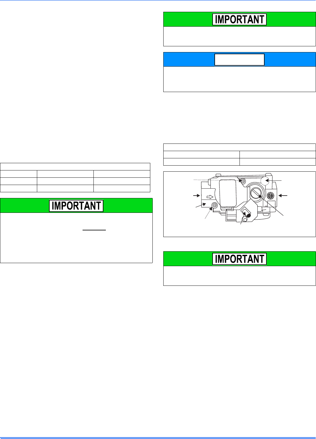
364861-UIM-H-0712
32 Johnson Controls Unitary Products
ADJUSTMENT OF MANIFOLD GAS PRESSURE &
INPUT RATE
Inlet and manifold gas pressure may be measured by connecting the
“U” tube manometer to the gas valve with a piece of tubing. Follow the
appropriate section in the instructions below. Refer to Figure 40 for a
drawing of the locations of the pressure ports on the gas valve.
Turn gas off at the ball valve or gas cock on gas supply line
before the gas valve. Find the pressure ports on the gas
valve marked Out P and In P.
1. The manifold pressure must be taken at the port marked OUT P.
2. The gas line pressure must be taken at the port marked IN P.
3. Using a 3/32” (2.4 mm) Allen wrench, loosen the set screw by turn-
ing it 1 turn counter clockwise. DO NOT REMOVE THE SET
SCREW FROM THE PRESSURE PORT.
Read the inlet gas pressure
Connect the positive side of the manometer to the IN P Tap on the gas
valve. Do not connect any tubing to the negative side of the manometer,
as it will reference atmospheric pressure. Refer to Figure 41 for connec-
tion details.
1. Turn gas and electrical supplies on and follow the operating instruc-
tions to place the unit back in operation.
2. Once the correct gas inlet pressure has been established, see
Table 15, turn the gas valve to OFF and turn the electrical supply
switch to OFF; then remove the flexible tubing from the gas valve
pressure tap and tighten the pressure tap plug using the 3/32” (2.4
mm) Allen wrench.
3. Turn the electrical and gas supplies back on, and with the burners
in operation, check for gas leakage around the gas valve pressure
port for leakage using an approved non-corrosive gas leak detec-
tion fluid, or other non-flammable leak detection methods.
Read the manifold gas pressure
Connect the positive side of the manometer to the adapter previously
installed in the OUT P Tap on the gas valve. Do not connect any tubing
to the negative side of the manometer, as it will reference atmospheric
pressure. Refer to Figure 41 for connection details.
1. Refer to Figure 40 for location of pressure regulator adjustment cap
and adjustment screws on main gas valve.
2. Turn gas and electrical supplies on and follow the operating instruc-
tions to place the unit back in operation.
3. Adjust manifold pressure by adjusting gas valve regulator screw for
the appropriate gas per the following:
4. After the manifold pressure has been adjusted, re-calculate the fur-
nace input to make sure you have not exceeded the specified input
on the rating plate. Refer to “CALCULATING THE FURNACE
INPUT (NATURAL GAS)”.
5. Once the correct BTU (kW) input has been established, turn the
gas valve to OFF and turn the electrical supply switch to OFF; then
remove the flexible tubing from the gas valve pressure tap and
tighten the pressure tap plug using the 3/32” (2.4 mm) Allen
wrench.
6. Turn the electrical and gas supplies back on, and with the burners
in operation, check for gas leakage around the gas valve pressure
port for leakage using an approved non-corrosive gas leak detec-
tion fluid, or other non-flammable leak detection methods.
Table 15: Inlet Gas Pressure Range
INLET GAS PRESSURE RANGE
Natural Gas Propane (LP)
Minimum 4.5” w.c. (1.12 kPa) 8.0” w.c. (1.99 kPa)
Maximum 10.5” w.c. (2.61 kPa) 13.0” w.c. (3.24 kPa).
The inlet gas pressure operating range table specifies what the mini-
mum and maximum gas line pressures must be for the furnace to
operate safely. The gas line pressure MUST BE a minimum of:
• 7” w.c. (1.74 kPA) for Natural Gas
• 11” w.c. (2.74 kPA) for Propane (LP) Gas
in order to obtain the BTU input specified on the rating plate and/or
the nominal manifold pressure specified in these instructions and on
the rating plate.
The cap for the pressure regulator must be removed entirely to gain
access to the adjustment screw. Loosening or tightening the cap does
not adjust the flow of gas.
The regulated outlet pressure has been calibrated at the factory.
Additional pressure adjustment should not be necessary. If adjust-
ment is necessary, set to the following specifications. After adjust-
ment, check for gas leakage.
Table 16: Nominal Manifold Pressure
NOMINAL MANIFOLD PRESSURE
Natural Gas 3.5" w.c. (0.87 kPa)
Propane (LP) Gas 10.0" w.c. (2.488 kPa)
FIGURE 41: Gas Valve
If gas valve regulator is turned in (clockwise), manifold pressure is
increased. If screw is turned out (counterclockwise), manifold pres-
sure will decrease.
NOTICE
INLET
WRENCH
BOSS
INLET
PRESSURE
PORT
ON
OFF
ON/OFF SWITCH
(Shown in ON position)
MAIN REGULATOR
ADJUSTMENT
OUTLET
OUTLET
PRESSURE
PORT
VENT PORT
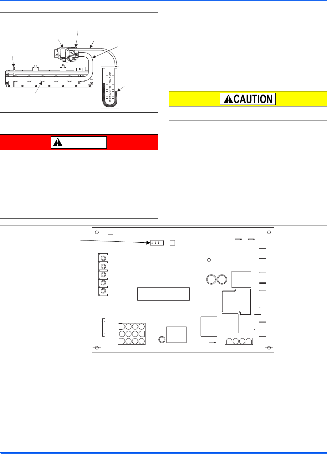
364861-UIM-H-0712
Johnson Controls Unitary Products 33
ADJUSTMENT OF TEMPERATURE RISE
After about 5 minutes of operation, determine the furnace temperature
rise. Take readings of both the return air and the heated air in the ducts,
about six feet (1.8 m) from the furnace where they will not be affected
by radiant heat. Increase the blower speed to decrease the temperature
rise; decrease the blower speed to increase the rise.
All direct-drive blowers have multi-speed motors. The blower motor
speed taps are located on the furnace control board in the blower com-
partment. Refer to Figure 42, and the unit-wiring label to change the
blower speed. To use the same speed tap for heating and cooling, the
heat terminal and cool terminal must be connected using a jumper wire
and connected to the desired motor lead. Place all unused motor leads
on Park terminals. Two park terminals are provided.
ADJUSTMENT OF FAN CONTROL SETTINGS
This furnace is equipped with a time-on/time-off heating fan control. The
fan on delay is fixed at 30 seconds. The fan off delay has 4 settings (60,
90, 120 and 180 seconds). The fan off delay is factory set to 120 sec-
onds. The fan-off setting must be long enough to adequately cool the
furnace, but not so long that cold air is blown into the heated space. The
fan-off timing may be adjusted by positioning the jumper on two of the
four pins as shown in Figure 42.
MANIFOLD PRESSURE “U” TUBE CONNECTION
FIGURE 42: Reading Gas Pressure
The temperature rise, or temperature difference between the return
air and the supply (heated) air from the furnace, must be within the
range shown on the furnace rating plate and within the application
limitations shown in Table 6.
The supply air temperature cannot exceed the “Maximum Supply
Air Temperature” specified in these instructions and on the furnace
rating plate. Under NO circumstances can the furnace be allowed to
operate above the Maximum Supply Air Temperature. Operating the
furnace above the Maximum Supply Air Temperature will cause pre-
mature heat exchanger failure, high levels of Carbon Monoxide, a fire
hazard, personal injury, property damage, and/or death.
U-TUBE
MANOMETER
3.5 IN
WATER
COLUMN
GAS
PRESSURE
SHOWN
GAS
BURNERS
OUTLET
PRESSURE TAP
GAS VALVE
FLAME
SENSOR
1/4” TUBING
MAINIFOLD
PIPE
DANGER
Do not energize more than one motor speed at a time or damage to
the motor will result.
FIGURE 43: Furnace Control Board
PARK PARK
HI COOL
HEAT
EAC-H
L1
XFMR
NEUTRALS
HUM
TWIN
60
90
120
180
BLOWER
OFF
DELAY
Y/Y2
WRGC
Blower Off Delay Timer
Adjustment Jumper
(in seconds)
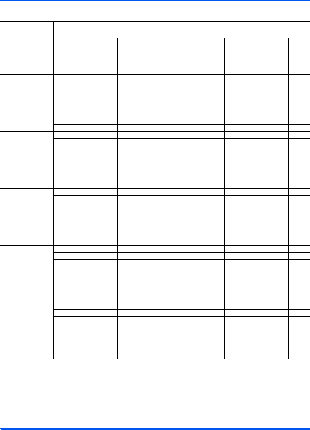
364861-UIM-H-0712
34 Johnson Controls Unitary Products
NOTES:
1.Airflow expressed in standard cubic feet per minute (CFM).
2.Motor voltage at 115 V.
Table 17: Blower Performance CFM - Any Position (without filter) - Bottom Return
Models
Input/Airflow/Cabinet Speed
Bottom Airflow Data (SCFM)
Ext. Static Pressure (in. H2O)
0.1 0.2 0.3 0.4 0.5 0.6 0.7 0.8 0.9 1.0
40/800/A
High 1128 1077 1035 996 950 891 842 781 708 646
Medium High 934 909 867 834 818 780 745 696 631 584
Medium Low 746 735 714 679 653 629 596 585 547 494
Low 676 652 627 601 581 542 516 474 441 383
60/1000/A
High 1360 1290 1230 1165 1103 1043 983 925 820 776
Medium High 1251 1198 1140 1089 1038 979 916 854 790 718
Medium Low 1081 1062 1015 964 917 871 819 767 710 634
Low 909 900 852 812 769 739 712 662 612 547
60/1200/B
High 1492 1442 1378 1325 1243 1176 1075 966 849 655
Medium High 1236 1201 1161 1139 1082 1011 919 830 715 590
Medium Low 986 950 961 916 872 831 757 703 600 510
Low 824 795 783 744 713 659 624 554 489 389
80/1200/B
High 1597 1537 1484 1435 1370 1286 1230 1155 1075 925
Medium High 1338 1307 1273 1223 1179 1123 1065 998 928 812
Medium Low 1113 1094 1077 1043 1008 972 924 868 803 798
Low 937 916 900 877 854 817 775 718 639 560
80/1600/C
High 1919 1865 1802 1738 1671 1600 1517 1414 1322 1201
Medium High 1532 1533 1513 1499 1465 1416 1352 1283 1198 1084
Medium Low 1232 1313 1291 1280 1250 1209 1207 1148 1055 937
Low 826 821 853 858 838 817 794 776 760 711
80/2200/C
High 2529 2435 2338 2256 2162 2041 1920 1794 1654 1501
Medium High 2166 2111 2070 2001 1927 1849 1719 1614 1499 1344
Medium Low 1697 1685 1664 1631 1586 1531 1466 1393 1315 1185
Low 1383 1377 1358 1336 1285 1244 1199 1147 1048 925
100/1600/C
High 1909 1880 1823 1776 1706 1637 1562 1474 1375 1252
Medium High 1465 1463 1469 1485 1477 1416 1386 1324 1250 1114
Medium 1190 1222 1216 1215 1224 1189 1158 1145 1087 996
Low 787 834 819 836 819 810 790 761 690 707
100/2000/C
High 2284 2205 2114 2021 1934 1848 1752 1653 1505 1397
Medium High 1967 1905 1824 1763 1712 1628 1551 1473 1379 1213
Medium Low 1610 1563 1513 1480 1430 1367 1319 1261 1101 1012
Low 1326 1304 1267 1232 1183 1143 1080 1003 871 798
120/1600/D
High 2020 1994 1958 1878 1805 1740 1647 1560 1445 1294
Medium High 1551 1559 1549 1520 1494 1451 1383 1334 1253 1145
Medium Low 1270 1267 1269 1269 1254 1227 1185 1121 1051 985
Low 932 916 905 894 876 828 803 725 754 696
120/2000/D
High 2341 2245 2153 2072 1977 1876 1769 1642 1506 1306
Medium High 2002 1952 1878 1823 1739 1657 1563 1458 1322 1185
Medium Low 1615 1579 1533 1473 1430 1368 1282 1186 1091 953
Low 1352 1295 1259 1245 1190 1141 1076 998 938 820
130/2000/D
High 2412 2329 2247 2173 2047 1980 1887 1777 1655 1511
Medium High 2040 2004 1948 1876 1786 1738 1656 1562 1461 1314
Medium Low 1614 1591 1549 1531 1459 1400 1335 1267 1180 1061
Low 1327 1294 1257 1224 1198 1171 1124 1036 944 848
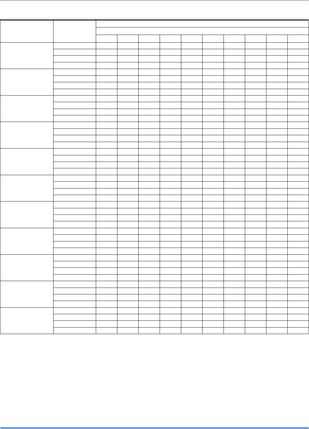
364861-UIM-H-0712
Johnson Controls Unitary Products 35
NOTES:
1.Airflow expressed in standard cubic feet per minute (CFM).
2.Return air is through side opposite motor (left side).
3.Motor voltage at 115 V.
4.Airflow through motor side (right side) may be slightly less than the data shown above.
Table 18: Blower Performance CFM - Any Position (without filter) - Left Side Return
Models
Input/Airflow/Cabinet Speed
Left Side Airflow Data (SCFM)
Ext. Static Pressure (in. H2O)
0.1 0.2 0.3 0.4 0.5 0.6 0.7 0.8 0.9 1.0
40/800/A
High 1131 1091 1053 1003 965 921 862 800 733 659
Medium High 982 959 935 887 846 795 745 675 628 595
Medium Low 772 736 715 689 661 642 599 568 531 493
Low 636 618 585 569 546 522 486 460 455 370
60/1000/A
High 1431 1375 1304 1244 1178 1109 1040 963 861 805
Medium High 1280 1226 1171 1117 1059 1004 930 865 781 731
Medium Low 1099 1050 1008 970 919 866 814 759 710 626
Low 914 876 842 812 770 728 694 661 612 545
60/1200/B
High 1470 1406 1361 1309 1241 1155 1060 920 775 628
Medium High 1211 1186 1139 1101 1042 980 896 796 681 545
Medium Low 970 957 927 889 853 796 745 660 568 450
Low 793 781 756 724 694 653 585 530 469 382
80/1200/B
High 1605 1562 1514 1454 1393 1330 1251 1169 1073 940
Medium High 1372 1318 1280 1255 1205 1161 1093 1023 943 849
Medium Low 1087 1073 1052 1003 993 953 897 843 775 709
Low 916 896 881 854 831 802 757 708 642 574
80/1600/C
High 1956 1907 1846 1778 1717 1647 1573 1483 1353 1209
Medium High 1543 1543 1516 1504 1477 1446 1382 1309 1202 1099
Medium Low 1238 1241 1243 1241 1252 1242 1201 1140 1074 967
Low 906 902 903 910 888 866 859 829 795 743
80/2200/C
High 2585 2492 2405 2321 2232 2137 2015 1902 1745 1577
Medium High 2098 2067 2036 1982 1928 1860 1767 1670 1549 1331
Medium Low 1619 1628 1614 1584 1545 1488 1424 1339 1216 1121
Low 1338 1347 1327 1301 1262 1199 1138 1078 1019 938
100/1600/C
High 1828 1829 1789 1768 1727 1671 1601 1505 1390 1272
Medium High 1422 1444 1437 1424 1396 1326 1301 1253 1200 1100
Medium 1224 1229 1243 1234 1219 1193 1168 1135 1088 977
Low 813 819 818 814 783 762 756 732 690 642
100/2000/C
High 2391 2286 2165 2079 2004 1934 1839 1692 1560 1366
Medium High 1945 1878 1838 1782 1694 1642 1565 1451 1334 1163
Medium Low 1549 1530 1495 1430 1431 1365 1284 1192 1097 1022
Low 1256 1229 1189 1159 1089 1033 1008 950 871 784
120/1600/D
High 1998 1987 1914 1858 1798 1721 1629 1530 1417 1303
Medium High 1512 1506 1492 1467 1441 1406 1342 1280 1206 1097
Medium Low 1217 1219 1210 1185 1174 1148 1112 1063 1012 937
Low 892 870 859 843 814 798 790 745 740 677
120/2000/D
High 2343 2253 2167 2071 1979 1881 1785 1668 1473 1351
Medium High 1954 1892 1846 1781 1714 1637 1548 1429 1238 1171
Medium Low 1596 1539 1511 1458 1399 1341 1254 1180 942 988
Low 1299 1261 1229 1177 1111 1053 993 937 882 782
130/2000/D
High 2425 2336 2255 2157 2046 1966 1865 1758 1615 1420
Medium High 1979 1959 1899 1825 1773 1686 1619 1516 1376 1225
Medium Low 1582 1567 1540 1488 1443 1406 1336 1252 1146 1033
Low 1305 1287 1239 1194 1159 1126 1062 1003 943 831
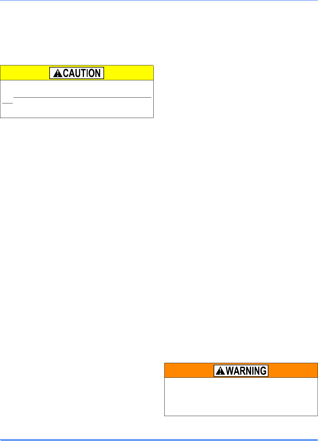
364861-UIM-H-0712
36 Johnson Controls Unitary Products
SECTION X: SAFETY CONTROLS
CONTROL CIRCUIT FUSE
A 3-amp fuse is provided on the control circuit board to protect the 24-
volt transformer from overload caused by control circuit wiring errors.
This is an ATO 3, automotive type fuse and is located on the control
board.
BLOWER DOOR SAFETY SWITCH
This unit is equipped with an electrical interlock switch mounted in the
burner compartment. This switch interrupts all power at the unit when
the panel covering the blower compartment is removed.
Electrical supply to this unit is dependent upon the panel that covers the
blower compartment being in place and properly positioned.
ROLLOUT SWITCH CONTROLS
These controls are mounted on the burner assembly. If the temperature
in the area surrounding burner exceeds its set point, the gas valve is
de-energized. The operation of this control indicates a malfunction in
the combustion air blower, heat exchanger or a blocked vent pipe con-
nection. Corrective action is required. These are manual reset controls
that must be reset before operation can continue.
PRESSURE SWITCHES
This furnace is supplied with two pressure switches, which monitor the
flow through the combustion air/vent piping and condensate drain sys-
tem. These switches de-energize the gas valve if any of the following
conditions are present. Refer to "CONDENSATE PIPING AND FUR-
NACE VENTING CONFIGURATION" for tubing connections.
1. Blockage of vent piping or terminal.
2. Failure of combustion air blower motor.
3. Blockage of combustion air piping or terminals.
4. Blockage of condensate drain piping.
LIMIT CONTROLS
There is a high temperature limit control located on the furnace vesti-
bule panel near the gas valve. This is an automatic reset control that
provides over temperature protection due to reduced airflow. This may
be caused by:
1. A dirty filter.
2. If the indoor fan motor should fail.
3. Too many supply or return registers closed or blocked off.
The control module will lockout if the limit trips 5 consecutive times. If
this occurs, control will reset & try ignition again after 1 hour.
SECTION XI: NORMAL OPERATION AND
DIAGNOSTICS
NORMAL OPERATION SEQUENCE
The following describes the sequence of operation of the furnace. Refer
to Owners Manual for component location.
Continuous Blower
Cooling/heating thermostats have a fan switch that has an ON and
AUTO position. In the ON position the thermostat circuit is completed
between terminals R and G. The motor will operate continuously on the
speed tap wire that is connected to the “HI COOL” cooling terminal on
the control board. To obtain a constant air circulation at lower flow rate,
change the high-speed wire to another lower speed wire.
Intermittent Blower - Cooling
Cooling/heating thermostats have a fan switch that has an ON and
AUTO position. In the AUTO position the thermostat circuit is completed
between terminals R and G when there is a call for cooling. The motor
will operate on the speed tap wire that is connected to the “HI COOL”
cooling terminal on the control board. The fan off setting is fixed at 60
seconds to improve cooling efficiency.
Heating Cycle
When the thermostat switch is set on HEAT and the fan is set on AUTO,
and there is a call for heat, a circuit is completed between terminals R
and W of the thermostat. When the proper amount of combustion air is
being provided, the pressure switch will close, the ignition control pro-
vides a 17-second ignitor warm-up period, the gas valve then opens,
the gas starts to flow, ignition occurs and the flame sensor begins its
sensing function. The blower motor will energize 30 seconds after the
gas valve opens, if a flame is detected. Normal furnace operation will
continue until the thermostat circuit between R and W is opened, which
causes the ignition system and gas valve to de-energize and the burner
flames to be extinguished. The vent motor will operate for 15 seconds
and the blower motor will operate for the amount of time set by the fan-
off delay jumper located on the control board. See Figure 42. The heat-
ing cycle is now complete, and ready for the start of the next heating
cycle.
If the flame is not detected within 7 seconds of the gas valve opening,
the gas valve is shut off and a retry operation begins. Also, if the flame
is lost for 2 seconds during the 10-second stabilization period, the gas
valve is shut off and a retry operation begins. During a retry operation,
the vent motor starts a 15 second inter-purge and the ignitor warm-up
time is extended to 27 seconds. If the flame is established for more than
10 seconds after ignition during a retry, the control will clear the ignition
attempt (retry) counter. If three retries occur during a call for heat, the
furnace will shut down for one hour. If at the end of the one hour shut
down there is a call for heat, the furnace will initiate a normal start cycle.
If the problem has not been corrected the furnace will again lockout
after three retries.
A momentary loss of gas supply, flame blowout, or a faulty flame probe
circuit will result in a disruption in the flame and be sensed within 1.0
seconds. The gas valve will de-energize and the control will begin a
recycle operation. A normal ignition sequence will begin after a 15 sec-
ond inter-purge. If during the five recycles the gas supply does not
return, or the fault condition is not corrected the ignition control will lock-
out for 60 minutes.
During burner operation, a momentary loss of power for 50 milliseconds
or longer will de-energize the gas valve. When the power is restored,
the gas valve will remain de-energized and the ignition sequence will
immediately restart.
TROUBLESHOOTING
The following visual checks should be made before troubleshooting:
1. Check to see that the power to the furnace and the ignition control
module is ON.
2. The manual shut-off valves in the gas line to the furnace must be
open.
3. Make sure all wiring connections are secure.
4. Review the sequence of operation. Start the system by setting the
thermostat above the room temperature. Observe the system’s
response. Then use the troubleshooting section in this manual to
check the system’s operation.
Main power to the unit must still be interrupted at the main power dis-
connect switch before any service or repair work is to be done to the
unit. Do not rely upon the interlock switch as a main power discon-
nect.
Blower and burner must never be operated without the blower panel
in place.
Never bypass any safety control to allow furnace operation. To
do so will allow furnace to operate under potentially hazardous
conditions.
Do not try to repair controls. Replace defective controls with
UPG Source 1 Parts.
Never adjust pressure switch to allow furnace operation.

364861-UIM-H-0712
Johnson Controls Unitary Products 37
FURNACE CONTROL DIAGNOSTICS
The furnace has built-in, self-diagnostic capability. A blinking LED light
on the control board can flash red, green or amber to indicate various
conditions. The control continuously monitors its own operation and the
operation of the system. If a failure occurs, the LED light will indicate
the failure code.
The SLOW flash speed is two seconds on and two seconds off.
The other flash codes listed below have the following timing: LED light
will turn on for 1/3 second and off for 1/3 second. This pattern will be
repeated the number of times equal to the code. There will be a two-
second pause between codes. For example, the six red flash code will
flash the LED light on and off six times, then will be off for two seconds.
This pattern will repeat as long as the fault condition remains. The con-
tinuous flash codes listed below will flash the LED light on and off con-
tinuously, with no breaks or longer pauses.
SLOW GREEN FLASH: Normal operation, no thermostat calls.
SLOW AMBER FLASH: Normal operation with call for heat.
LED STEADY OFF – If the LED light does not flash at all, check for
power to the board and check for a blown fuse on the board. If the
board is properly powered and the fuse is not blown, the control board
may need to be replaced.
STEADY ON ANY COLOR: Control failure. Turn power to the furnace
off and back on. If the fault code returns, the control board must be
replaced. The control board is not field-repairable.
CONTINUOUS GREEN FLASH: Twinning error, incorrect 24V phasing
or no power to twinned unit. Check twinning wiring. Confirm that both
twinned units have power.
CONTINUOUS AMBER FLASH: Flame sense current is below 1.5
microamps. Check and clean flame sensor. Check for proper gas flow.
Verify that current is greater than 1.5 microamps at flame current test
pad.
1 RED FLASH: This indicates that flame was sensed when there was
not a call for heat. The control will turn on both the inducer motor and
supply air blower. Check for a leaking or slow-closing gas valve.
2 RED FLASHES: This indicates that the pressure switch is closed
when it should be open. The control confirms that the pressure switch
contacts are open at the beginning of each heat cycle and will not let
the ignition sequence continue if the pressure switch contacts are
closed when they should be open. Check for a faulty pressure switch or
miswiring.
3 RED FLASHES: This indicates the pressure switch contacts are open
when they should be closed. Check for faulty inducer, blocked vent
pipe, broken pressure switch hose, disconnected pressure switch or
inducer wires or faulty pressure switch.
4 RED FLASHES: This indicates that the main limit switch has opened
its normally closed contacts. The control will operate the supply air
blower and inducer while the open limit condition exists. Check for a
dirty filter, improperly sized duct system, incorrect blower speed setting,
incorrect firing rate, loose limit switch wiring or faulty blower motor.
If the limit switch has not closed within five minutes, the control will
assume that the blower is not functioning, will start a hard lockout and
will begin to flash the 11 Red Flashes error code. Power will have to be
cycled off and on to reset the control after the problem has been cor-
rected. See “11Red Flashes” description below.
If the main limit switch opens five times within a single call for heat, the
control will also indicate 4 Red Flashes and will enter a one-hour soft
lockout.
5 RED FLASHES: This fault is indicated if the normally closed rollout
switch opens. The rollout control is manually reset. Check for proper
combustion air, proper inducer operation, and primary heat exchanger
failure or burner problem. The control will enter a hard lockout and
power will have to be cycled off and on to reset the control after the
problem has been corrected.
6 RED FLASHES: This indicates that while the unit was operating, the
pressure switch opened four times during the call for heat. Check for
faulty inducer, blocked vent pipe or faulty pressure switch. The furnace
will lock out for one hour and then restart.
7 RED FLASHES: This fault code indicates that the flame could not be
established during three trials for ignition. Check that the gas valve
switch is in the ON position. Check for low or no gas pressure, faulty
gas valve, dirty or faulty flame sensor, faulty hot surface ignitor, loose
wires or a burner problem. The furnace will lock out for one hour and
then restart.
8 RED FLASHES: This fault is indicated if the flame is lost five times
(four recycles) during the heating cycle. Check for low gas pressure,
dirty or faulty flame sensor or faulty gas valve. The furnace will lock out
for one hour and then restart.
9 RED FLASHES: Indicates reversed line voltage polarity, grounding
problem or reversed low voltage transformer wires. Both heating and
cooling operations will be affected. Check polarity at furnace and
branch. Check furnace grounding. Check that flame probe is not
shorted to chassis. The furnace will not start the ignition sequence until
this problem is corrected.
10 RED FLASHES: Gas valve energized with no call for heat. The main
blower and inducer blower will run and no ignition sequence will be
started as long as this condition exists. Check gas valve and gas valve
wiring.
11 RED FLASHES: This indicates that the main limit switch has opened
its normally-closed contacts and has remained open for more than five
minutes. This condition is usually caused by a failed blower motor or
blower wheel. The control will enter a hard lockout and power will have
to be cycled off and on to reset the control after the problem has been
corrected.
4 AMBER FLASHES: The control is receiving a “Y” signal from the
thermostat without a “G” signal. The furnace will operate normally in
both heating and cooling, but this fault code will be displayed in order to
alert the user that there is a wiring problem. Verify that the “G” wire from
the thermostat is connected properly.
SOFT LOCKOUT: This control includes a soft lockout that will reset
automatically after one hour. This provides protection to an unoccupied
structure if a temporary condition exists causing a furnace malfunction.
An example of this is a temporary interruption in gas supply that would
prevent the furnace from lighting. The control will keep trying to light
each hour and will resume normal operation if the gas supply is
restored.
HARD LOCKOUT: Some fault conditions result in a hard lockout, which
requires power to the control to be turned off and then back on to reset
the control. The control will not automatically restart.
IGNITION CONTROL FLAME SENSE LEVELS
Normal flame sense current is approximately
3.7 microamps DC (µa)
Low flame signal warning starts at 1.5 microamps.
Low flame signal control lockout point is
0.1 microamps DC (µa)
364861-UIM-H-0712
38 Johnson Controls Unitary Products
DIAGNOSTIC FAULT CODE STORAGE AND
RETRIEVAL
The control in this furnace is equipped with memory that will store up to
five error codes to allow a service technician to diagnose problems
more easily. This memory will be retained even if power to the furnace
is lost. This feature should only be used by a qualified service tech-
nician.
If more than five error codes have occurred since the last reset, only the
five most recent will be retained. The furnace control board has a but-
ton, labeled "LAST ERROR" that is used to retrieve error codes. This
function will only work if there are no active thermostat signals. So any
call for heating, cooling or continuous fan must be terminated before
attempting to retrieve error codes.
To retrieve the error codes, push the LAST ERROR button. The LED on
the control will then flash the error codes that are in memory, starting
with the most recent. There will be a two-second pause between each
flash code. After the error codes have all been displayed, the LED will
resume the normal slow green flash after a five second pause. To
repeat the series of error codes, push the button again.
If there are no error codes in memory, the LED will flash two green
flashes. To clear the memory, push the LAST ERROR button and hold it
for more than five seconds. The LED will flash three green flashes when
the memory has been cleared, then will resume the normal slow green
flash after a five-second pause.
SECTION XII: REPLACEMENT PARTS LIST
DESCRIPTION
MOTOR
MOTOR, DIRECT DRIVE BLOWER
BLOWER, COMBUSTION
ELECTRICAL
CAPACITOR, RUN
SWITCH, LIMIT
CONTROL, FURNACE
IGNITER
SENSOR, FLAME
SWITCHES, PRESSURE
SWITCH, DOOR
TRANSFORMER
VALVE, GAS
CONTROL, TEMPERATURE
AIR MOVING
HOUSING, BLOWER
WHEEL, BLOWER
FABRICATED PARTS
RESTRICTOR, COMBUSTION BLOWER
BURNER, MAIN GAS
BRACKET, IGNITER
SHELF, BLOWER
RAIL, BLOWER (2 Req’d)
BRACKET, BLOWER TRACK (2 Req’d)
HEAT EXCHANGER ASS’Y
FABRICATED PARTS Continued
MANIFOLD, GAS
PAN, BOTTOM
PANEL, TOP
PANEL, DOOR (2 Req’d)
PANEL, BLOCKOFF
MISCELLANEOUS
ORIFICE, BURNER (Natural #45)
SIGHT GLASS, OVAL (2 Req’d)
GASKET, FOAM (Door) (1.5 ft req’d)
PAN, CONDENSATE
BRACKET, DOOR
HARNESS, WIRING
FERRULE (3 Req’d)
GROMMET (3 Req’d)
MOTOR MOUNT
TUBING, SILICON
HOSE, RAIN GUTTER
HOSE, CONDENSATE
PLUG, SEAL, 7/8”
PLUG, SEAL, 2-3/8”
PLUG, VENT PIPE
BAG, PARTS
KNOB, QUARTER TURN (4 Req’d)
DIAGRAM, WIRING
DESCRIPTION
REPLACEMENT PART CONTACT INFORMATION
This is a generic parts list. To request a complete parts list, refer to the contact information below:
• Visit our website at www.source1parts.com for the following information:
1. Search for a part or browse the catalog.
2. Find a dealer or distributor.
3. Customer Service contact information.
a. Click on the “Brand Links” button
b. Click on the “Customer Service” buttont
• You can contact us by mail. Just send a written request to:
Johnson Controls Unitary Products
Consumer Relations
5005 York Drive
Norman, OK 73069
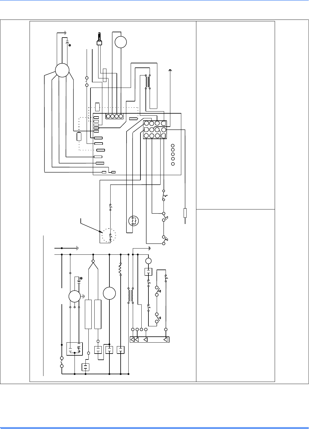
364861-UIM-H-0712
Johnson Controls Unitary Products 39
SECTION XIII: WIRING DIAGRAM
FIGURE 44: Wiring Diagram
Wiring Diagram - 95% Single-Stage Furnace
MOT
IDM
EAC
HUM
COOL
HEAT
EAC
HUM
HSI
HUM
DS
TST
GND
GND
GV
LS
PS1
EAC
R
G
Y
W
EAC
HUM
BRN
ROS
ROS
W
Y
G
C
R
BLU
BLU - MED HI
BLK
DS
GRN
BRN
BRN GND
HSI
IDM
BLK - HI
YEL - MED LOW
RED - LOW
WHT
MOT
GRN
GND
BRN
BLK
WHT
GRY
GRY
TAN
TAN
WHT
WHT
WHT 115VAC
24V SEC
115V COM
PRI
XFMR
FURNACE CONTOL
24V SEC
115V COM
XFMR
PRI
115VAC
1
2
3
4
1
2
C
1
2
3
4
5
6
8
7
9
10
11
12
C
G
R
W
Y/Y2
PARK PARK
XFMR
EAC-H
HEAT
HI COOL
L1
NEUTRALS
C
C
NO
NO
NO
ROS ROS
FS
GV
PS2
RED/WHT
RED/BLK
YEL
RED
YEL
PRP
ORN/BLK
RED
ORN
RED/GRN
C
LS
12
NO
WHT
SEE NOTE 2
C
NO
PS1
PS2
CNO
THE 40,000 INPUT
FURNACE HAS ONLY
ONE ROLLOUT SWITCH
HUM
364665-UWD-F-0212
DS -
ROS -
FS -
TST -
PS1 -
PS2 -
1. If any of the original wire as supplied with the furnace must be replaced, it must
be replaced with wiring material having a temperature rating of at least
221 degrees F (105 degrees C ).
2. Blower motor speed connections shown are typical, but may vary by model and
application.
LS -
HUM -
XFMR -
GV -
DS -
ROS -
XFMR -
LS -
HSI -
PS1 -
PS2 -
1. Si l'un des fils d'origine fourni avec ce four doit être remplacé, il doit être remplacé
avec le fil ayant un degré de température d'au moins 221 degrés F (105 degrés C ).
2. Les connexions à grande vitesse du moteur du ventilateur indiqués sont typiques, mais
peuvent varier selon le modèle et par application.
Legend Legende
MOT -
IDM -
CAP -
HSI -
EAC -
TST -
FS -
CAP -
EAC -
Door switch
Rollout switch
Flame sensor
Wall thermostat
Pressure switch
Condensate pressure switch
Circulating motor
Inducer motor
Capacitor
Hot surface igniter
Electronic air cleaner
Limit switch
Humidifier
Transformer
Gas valve
Commutateur de porte
Commutateur de roulement
Transformeur
Commutateur de limite
Ignition de surface chaud
Commutateur de pression
Commutateur de pression, condensation
MOT -
IDM -
GV -
HUM -
Moteur soufflerie
D'induct moteur
Soupape de gaz
Humidificateur
Thermostat
Capteur de flame
Capaciteur
Filtre électrique
CAP
CAP

Subject to change without notice. Published in U.S.A. 364861-UIM-H-0712
Copyright © 2012 by Johnson Controls, Inc. All rights reserved. Supersedes: 364861-UIM-G-1211
York International Corp.
5005 York Drive
Norman, OK 73069
NOTES
