Johnson Controls WRZRADIO WRZ Radio Module User Manual WRZ Radio Module User Guide Rev 5
Johnson Controls Inc WRZ Radio Module WRZ Radio Module User Guide Rev 5
manual
User Guide WRZ Radio Module 2.4G
Issue Date May 31, 2012
This document contains trade secrets and proprietary information of Johnson Controls, Inc. Disclosure of this publication is absolutely
prohibited without the express written permission of Johnson Controls, Inc. Johnson Controls, Inc., 2012. All rights reserved. © 1
WRZ Radio Module - User Guide
2.4GHz RF Transceiver Module
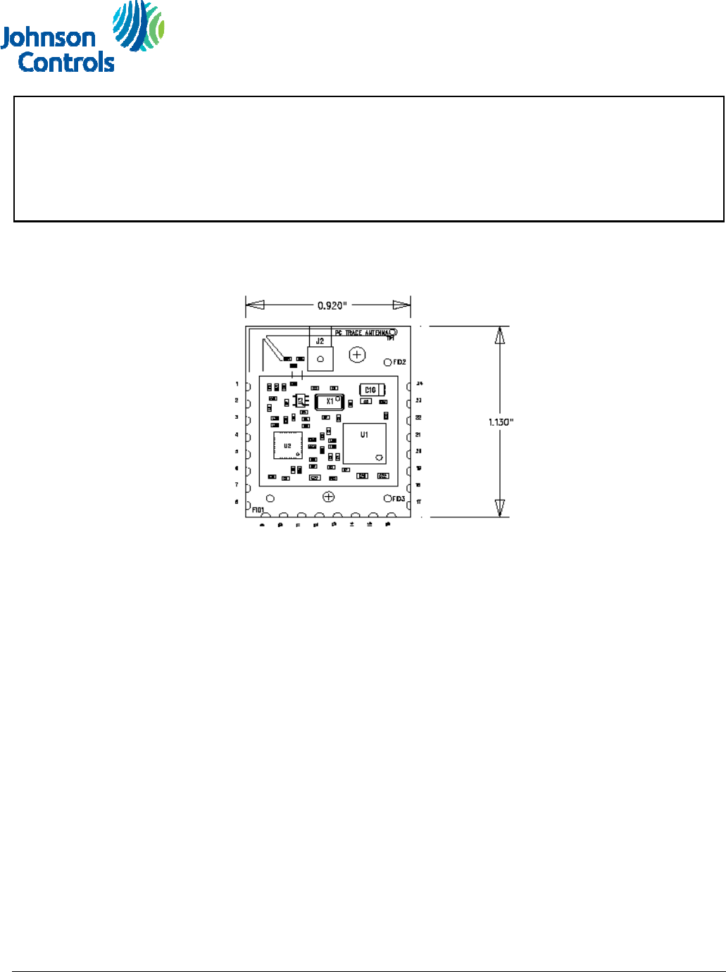
Figure 1: 2.4GHz WRZ Radio Module
Note: This WRZ Radio 2.4G RF Module is designed to be used internally only in Johnson
Controls products. It is not intended to be sold as an end item by itself to external customers.
The Johnson Controls WRZ Radio 2.4G RF Module is a single printed wiring board that implements a self
contained, complete wireless interface module. The radio section utilizes Texas Instruments CC2530 radio
chip, following the 802.15.4 standard and is driven by a 32.000 MHz crystal circuit on board. The CC2530
chip drives a balun which couples the signal to an RF amplifier delivering 10 mW to either an internal F
antenna or external antenna through a MMCX connector to the approved antenna.
The RF power output for the transmit amplifier is limited to 10 dBm. The RF Module is designed to be
mounted in various plastic enclosures depending on the requirements of the product and interface protocol.
The RF Module is a completely self contained radio module which has its own RF shielding. No other RF
shielding is required or implemented. It modulates its own RF transmitter. It controls the data flow to the
transmitter section compliant with FCC Part 15 requirements. The module uses ZigBee channels 11 -26 in
the 2450 MHz band.

User Guide WRZ Radio Module 2.4G
Issue Date May 31, 2012
2 WRZ Radio 2.4GHz Module User Guide
Model Number and Description
MODEL NUMBER DESCRIPTION
25-2845 Internal circuit board trace antenna or external antenna as defined by
the board assembly options.
Power Requirements:
There is not a hardware voltage regulator on board. The unit operates within the stated FCC part 15 requirements
when operated within the specified supply voltage range of 2.3VDC to 3.6VDC (3.0VDC nominal). The unit will not
transmit if the supply voltage exceeds the maximum. Current drain is approximately 50mA during transmission, 35mA
when receiving, and 5 micro-Amps with the radio off in sleep mode.
Connection to Motherboard:
The Radio Module is intended to connect to a motherboard using 24, surface to surface solder pads. This interface is
for the 3.0 VDC power source and all necessary data lines to communicate with the radio module. The pins can be
configured for various serial data and general purpose input/output functions.
*Pin # Name Type Description
1 GROUND GND Ground
2 PO_2 DI/DO/AI General Purpose Digital I/0 Port 0_2 or ADC input 2
3 PO_3 DI/DO/AI General Purpose Digital I/0 Port 0_3 or ADC input 3
4 PO_4 DI/DO/AI General Purpose Digital I/0 Port 0_4 or ADC input 4
5 PO_5 DI/DO/AI General Purpose Digital I/0 Port 0_5 or ADC input 5
6 PO_6 DI/DO/AI General Purpose Digital I/0 Port 0_6 or ADC input 6
7 PO_7 DI/DO/AI General Purpose Digital I/0 Port 0_7 or ADC input 7
8 GROUND GND Ground
9 P2_2 DI/DO General Purpose Digital I/O Port 2_2 or Debug CLK
10 P2_1 DI/DO General Purpose Digital I/O Port 2_1 or Debug DATA (DD)
11 P2_0 DI/DO General Purpose Digital I/O Port 2_0
12 P1_7 DI/DO General Purpose Digital I/O Port 1_7
13 P1_6 DI/DO General Purpose Digital I/O Port 1_6
14 TXD DI/DO General Purpose Digital I/O Port 1_5 or Application Transmit Data Output
15 RXD DI/DO General Purpose Digital I/O Port 1_4 or Application Receive Data Input
16 P1_3 DI/DO General Purpose Digital I/O Port 1_3
17 GROUND GND Ground
18 P1_1 DI/DO General Purpose Digital I/O Port 1_1, 20mA drive capability
19 P1_0 DI/DO General Purpose Digital I/O Port 1_0, 20mA drive capability
20 RESET DI Reset, active low
21 P0_0 DI/DO/AI General Purpose Digital I/0 Port 0_0 or ADC input 0
Optional on-board Green LED
22 P0_1 DI/DO/AI General Purpose Digital I/0 Port 0_1 or ADC input 1
Optional on-board Red LED
23 VDD PI Power Supply Input
24 GROUND GND Ground
*For pin # see Figure 1
Unused I/O pins should be left unconnected and the pin state set via the Host Protocol.
DI = Digital Input PI = Power Input DO = Digital Output GND = Ground

User Guide WRZ Radio Module 2.4G
Issue Date May 31, 2012
3 WRZ Radio 2.4GHz Module User Guide
FCC and Industry Canada:
The JCI user manual for the end product that has this radio module integrated in to it must include
the following information in a prominent location:
“To comply with FCC and Industry Canada RF radiation exposure limits for general population, the
antenna(s) used for this transmitter must be installed such that a minimum separation distance of 20cm
is maintained between the radiator (antenna) and all persons at all times and must not be co-located or
operating in conjunction with any other antenna or transmitter.”
The manual must also not provide information regarding how to install or remove this RF module or change RF
related parameters.
The Johnson Controls WRZ Radio 2.4G RF module has been certified for integration into products only by OEM
integrators under the following conditions:
1) The antenna must be installed such that a minimum separation distance of 20 cm is maintained between the
radiator (antenna) and all persons at all times.
2) The transmitter module must not be co-located or operating in conjunction with any other antenna or
transmitter.
As long as the two conditions above are met, further transmitter testing will not be required. However, the OEM
integrator (JCI only) is still responsible for testing their end-product for any additional compliance requirements
required with this module installed (for example, digital device emissions).
IMPORTANT NOTE: In the event that these conditions cannot be met (for certain configurations or co-location with
another transmitter), then the FCC and Industry Canada authorizations are no longer considered valid and the FCC
ID and IC Certification Number cannot be used on the final product. In these circumstances, the OEM integrator
(JCI) will be responsible for re-evaluating the end product (including the transmitter) and obtaining a separate FCC
and Industry Canada authorization.
END PRODUCT LABELING
The WRZ Radio 2.4G RF Module is labeled with its own FCC ID and IC Certification Number. If the FCC ID and IC
Certification Number are not visible when the module is installed inside another device, then the outside of the
device into which the module is installed must also display a label referring to the enclosed module. In that case, the
final end product must be labeled in a visible area with the following:
“Contains Transmitter Module FCC ID:OEJ-WRZRADIO”
“Contains Transmitter Module IC: 279A-WRZRADIO”
Or
“Contains FCC ID: OEJ-WRZRADIO”
“Contains IC: 279A-WRZRADIO”
The WRZ Radio 2.4G RF Module must only use the approved antenna(s) listed in this document, which have been
certified with this module.

User Guide WRZ Radio Module 2.4G
Issue Date May 31, 2012
4 WRZ Radio 2.4GHz Module User Guide
FCC Compliance:
An FCC ID label is to be affixed to each unit at the time of manufacture. Since this printed circuit board is
mounted inside various enclosures, the product data nameplate on that enclosure indicates the FCC ID. The
Johnson Controls WRZ Radio 2.4G RF Module is compliant with Part 15.247.
Compliance Statement (Part 15.19)
This device complies with Part 15 of the FCC Rules.
Operation is subject to the following two conditions:
1. This device may not cause harmful interference, and
2. This device must accept any interference received, including
interference that may cause undesired operation.
Warning (Part 15.21)
Changes or modifications not expressly approved by the party
responsible for compliance could void the user’s authority to operate
the equipment.
Industry Canada Certification:
An IC ID label is to be affixed to each unit at the time of manufacture. Since this printed circuit board is
mounted inside various enclosures, the product data nameplate on that enclosure indicates the IC ID.
Industry Canada Statement
The term IC before the certification/registration number only signifies
that the Industry Canada technical specifications were met.
Le terme « IC » précédant le numéro d'accréditation/inscription signifie
simplement que le produit est conforme aux spécifications techniques
d'Industry Canada.
Under Industry Canada regulations, this radio transmitter may only operate using an antenna of a type and
maximum (or lesser) gain approved for the transmitter by Industry Canada. To reduce potential radio
interference to other users, the antenna type and its gain should be so chosen that the equivalent
isotropically radiated power (e.i.r.p.) is not more than that necessary for successful communication.
This radio transmitter has been approved by Industry Canada to operate with the antenna type listed below
with the maximum permissible gain and required antenna impedance for the antenna type indicated.
Antenna types not included in this list, having a gain greater than the maximum gain indicated for that type,
are strictly prohibited for use with this device.
This device has been designed to operate with the antenna listed below and having a maximum gain of 2
dBi. Antennas not included in this list or having a gain greater than 2 dBi are strictly prohibited for use with
this device. The required antenna impedance is 50 ohms.

User Guide WRZ Radio Module 2.4G
Issue Date May 31, 2012
5 WRZ Radio 2.4GHz Module User Guide
This Device complies with Industry Canada License–exempt RSS standard(s). Operation is subject to the
following two conditions: 1) this device may not cause interference, and 2) this device must accept any
interference, including interference that may cause undesired operation of the device.
Conformément à la réglementation d'Industrie Canada, le présent émetteur radio peut fonctionner avec une antenne
d'un type et d'un gain maximal (ou inférieur) approuvé pour l'émetteur par Industrie Canada. Dans le but de réduire
les risques de brouillage radioélectrique à l'intention des autres utilisateurs, il faut choisir le type d'antenne et son
gain de sorte que la puissance isotrope rayonnée équivalente (p.i.r.e.) ne dépasse pas l'intensité nécessaire à
l'établissement d'une communication satisfaisante.
Le présent émetteur radio IC a été approuvé par Industrie Canada pour fonctionner avec les types d'antenne
énumérés ci-dessous et ayant un gain admissible maximal et l'impédance requise pour chaque type d'antenne. Les
types d'antenne non inclus dans cette liste, ou dont le gain est supérieur au gain maximal indiqué, sont strictement
interdits pour l'exploitation de l'émetteur.
Cet appareil a été conçu pour fonctionner avec les antenne énumérés ci-dessous et d'un gain maximum de 2 dBi.
L'utilisation d'une antenne autre ou d'un gain supérieur est strictement interdite. L'impédance d'antenne requise est
de 50 ohms.
Le présent appareil est conforme aux CNR d'Industrie Canada applicables aux appareils radio exempts de licence.
L'exploitation est autorisée aux deux conditions suivantes : (1) l'appareil ne doit pas produire de brouillage, et (2)
l'utilisateur de l'appareil doit accepter tout brouillage radioélectrique subi, même si le
brouillage est susceptible d'en compromettre le fonctionnement.
Antenna:
The WRZ Radio 2.4G RF Module employs a circuit board trace F antenna or an optional dipole antenna utilizing a 48
inch cable and MMCX connector. The external antenna is a Nearson model S131CL-48-MM-2450S.
La radio 2.4 GHz qui équipe le WRZ utilise une antenne circuit imprimé ou une antenne optionnelle connectée a
l'aide un connecteur MMCX. L'antenne externe est fabriquée par Nearson, modèle S131CL-48-MM-2450S.
References:
• JCI Drawing 25-2845 Assembly
• JCI Product Specification 06-528-8