Johnson Outdoors IPCON Controller for Trolling Motor on Fishing Boat User Manual
Johnson Outdoors, Inc. Controller for Trolling Motor on Fishing Boat
UserManual.wiki
>
Johnson Outdoors
>
IPCON User Manual
>
manual pt 1
Contents
1.
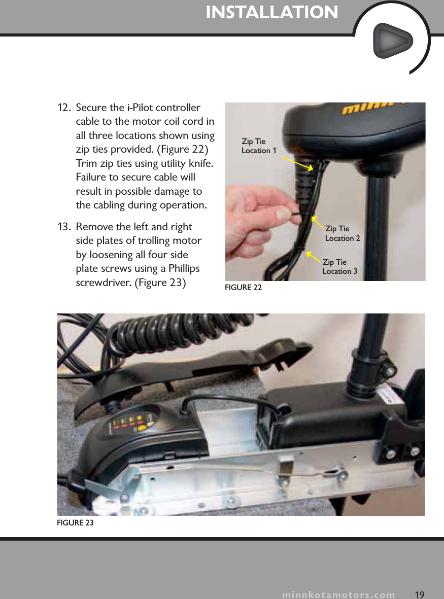
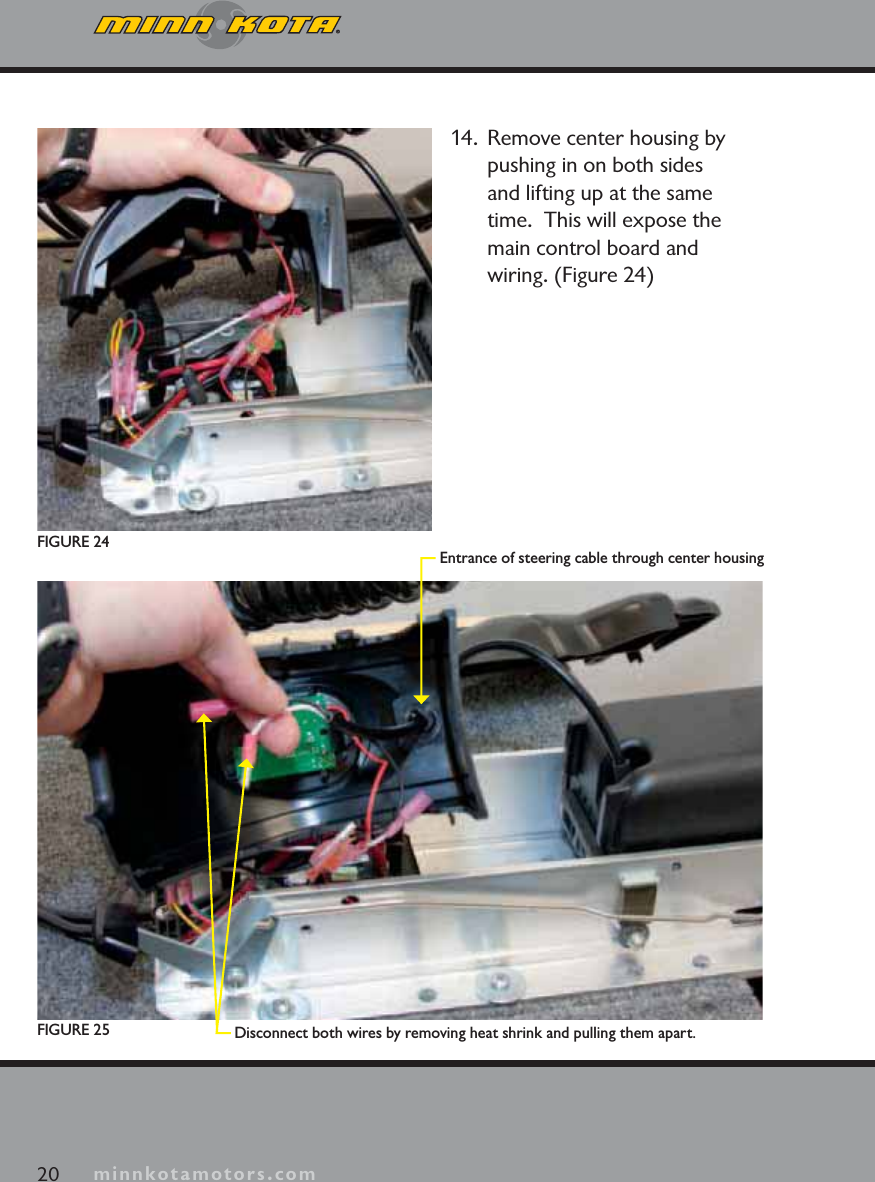
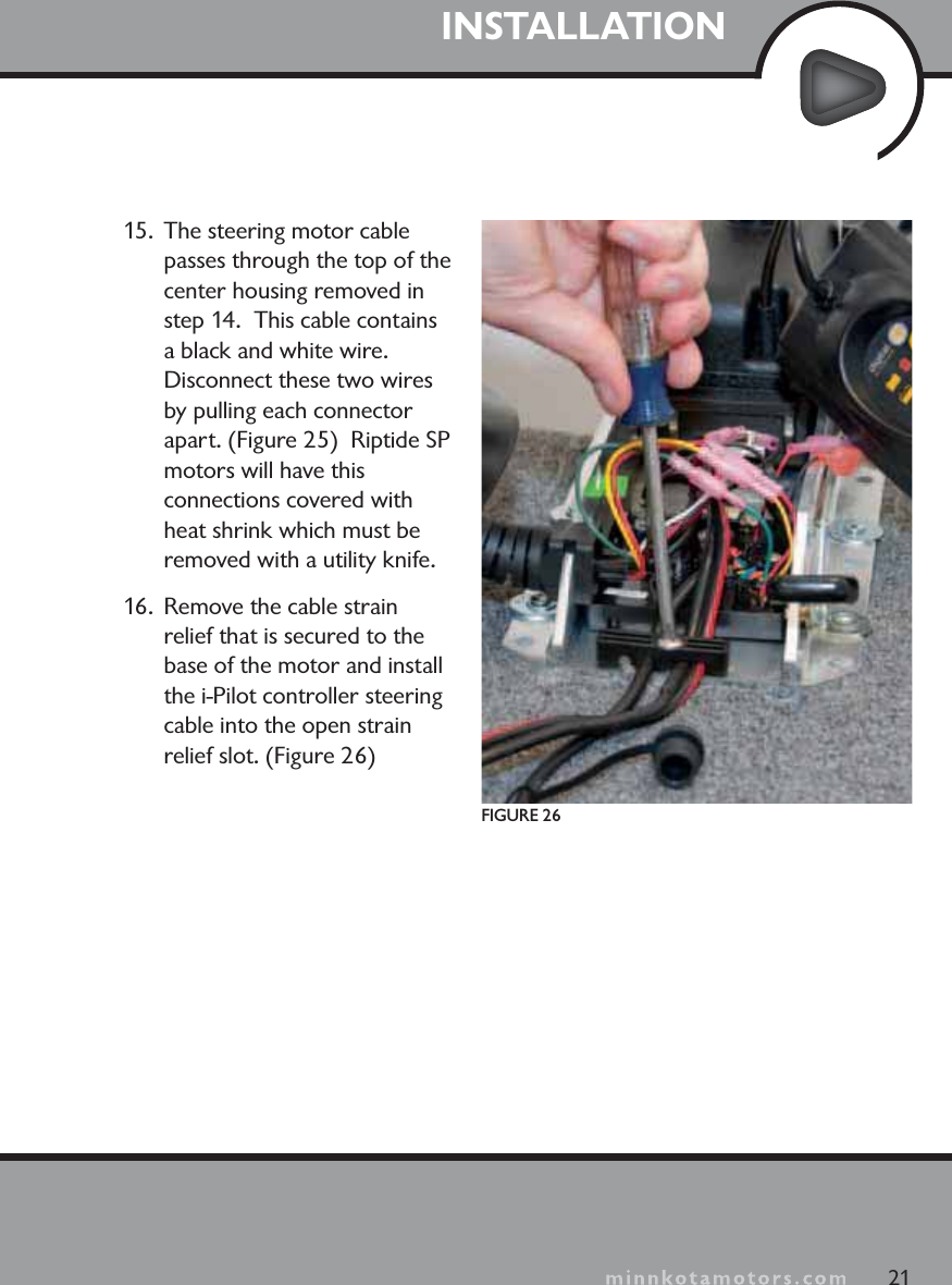
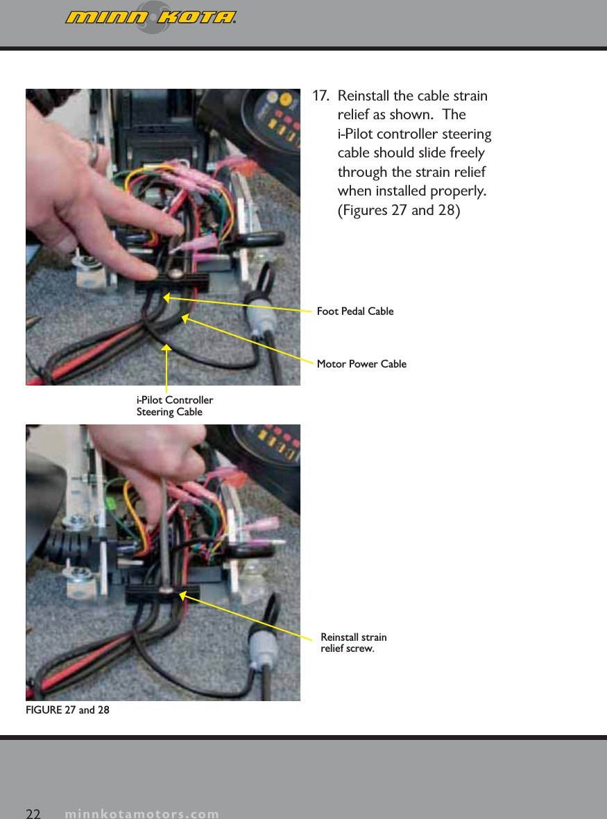
manual pt 1
2.
manual pt 2
manual pt 1
Navigation menu
Upload a User Manual
Namespaces
Wiki Guide
HTML
PDF
Info
Views
User Manual
Discussion / Help
Navigation