Johnson Outdoors IPREM20 i-Pilot Link System User Manual 2
Johnson Outdoors, Inc. i-Pilot Link System 2
Contents
- 1. User Manual 1
- 2. User Manual 2
- 3. User Manual 3
- 4. User Manual 4
- 5. User Manual 5
User Manual 2
19
minnkotamotors.com
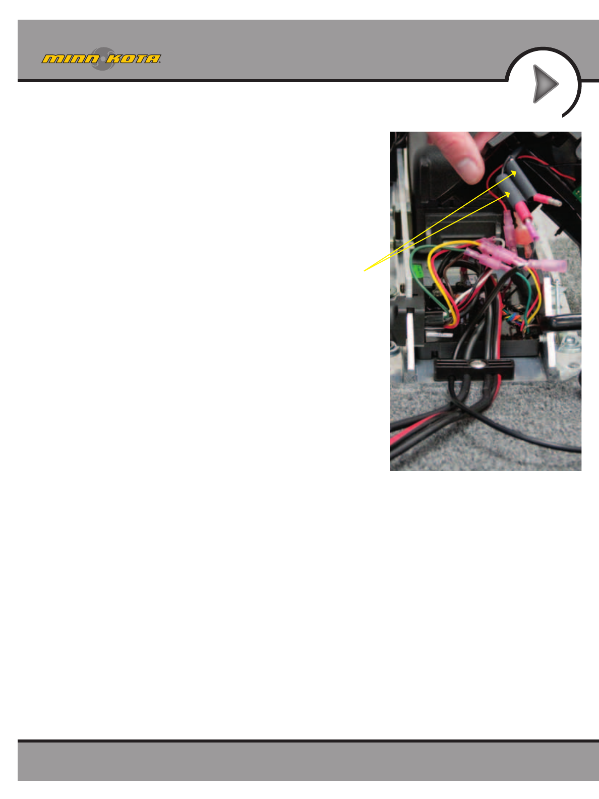
INSTALLATION
FIGURE 32
Slide heat shrink
over steering
motor wires.
18. Slide four pieces of heat shrink insulation over each side of the
wires that were disconnected in step 15. (Figure 32)
20
minnkotamotors.com
INSTALLATION
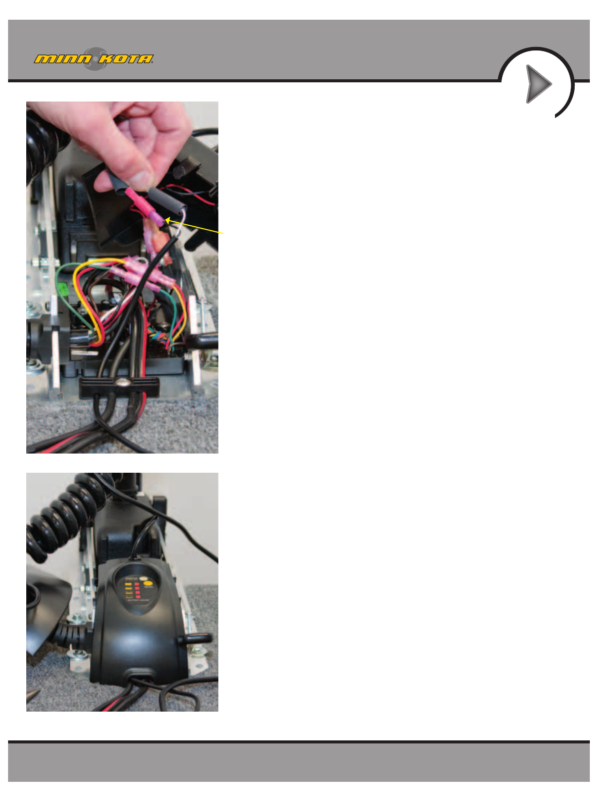
FIGURE 33
Connect
steering wires:
white to white
black to black
19. Connect the black and white wires from the i-Pilot Link
controller cable to the black and white steering motor
wires, making sure black is connected to black and white
is connected to white. (Figure 33)
20. Complete the installation by positioning the heat shrink
over the connections and shrink down, using a heat gun
or other heat source, being careful not to overheat any
wire or parts.
Seal connections with heat shrink.
IMPORTANT: DO NOT OVERHEAT WIRES OR
SURROUNDING PARTS WHEN INSTALLING
HEAT SHRINK!
21. Reinstall center housing over control board by pushing it
down until the side fingers lock into place. The new
i-Pilot Link Controller steering cable should be exiting
the cable exit hole at the center and bottom of the
center housing. (Figure 34)
FIGURE 34
21
minnkotamotors.com
INSTALLATION
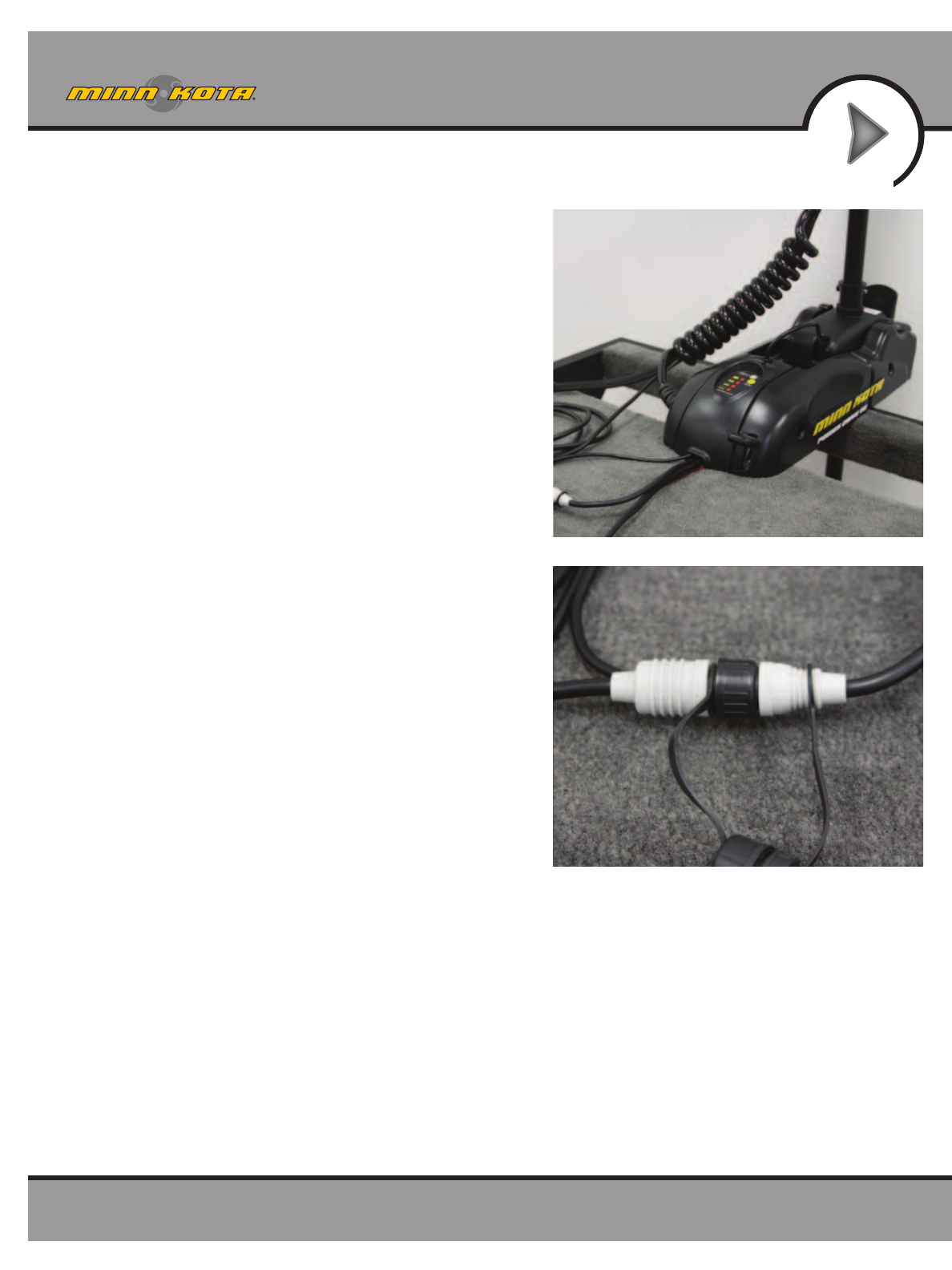
FIGURE 35
FIGURE 36
22. Reinstall both side plates using Phillips screwdriver. If
a Co-Pilot was uninstalled, use new ¼-20 x 5⁄8" Phillips
screws provided. (Figure 35)
23. If a foot pedal is connected to the trolling motor, it
must be disconnected. Once i-Pilot Link has been
installed the foot pedal cannot be used unless i-Pilot Link
is completely uninstalled.
24. Connect i-Pilot Link controller cable to the foot pedal
connector, making sure the connector nut is tight
(Figure 36)
IMPORTANT: DO NOT place dielectric grease or any type
of lubricant in the connector.
25. i-Pilot Link is now installed on the motor. Skip ahead to
the next section to verify the installation.
22
minnkotamotors.com
INSTALLATION
VERIFYING INSTALLATION OF I-PILOT LINK
CONTROLLER AND REMOTE
It is important to verify your i-Pilot Link installation prior to going on the water. If this cannot be done, it is highly
recommended that system verification be done in an open area on a calm day with a fully operational outboard motor
for a backup means of powering your boat.
To verify that i-Pilot Link is working properly before going on the water, follow the steps below.
1. Trolling motor should be correctly installed and mounted to the bow of a boat.
2. The boat and trolling motor must be located outside and have a direct view of the sky to obtain
GPS satellite signals.
3. Verify that all obstructions are away from the prop in all directions in both the stowed and deployed positions.
4. Connect power to the trolling motor.
5. Deploy the motor so the motor shaft is completely vertical.
6. The i-Pilot Link controller will emit four short beeps on startup.
7. Turn on the remote by pressing the OK key.
8. The i-Pilot Link remote LCD will come on. In the Header section of the LCD, monitor the GPS Signal Strength
icon. It should take no longer than two minutes to obtain a GPS signal strength of at least one bar.
9. When i-Pilot Link is powered up, it starts to gather satellite information about its location. A minimum satellite
signal level must be achieved before all i-Pilot Link functionality is available. This minimum level is one bar on the
GPS signal icon. With no bars showing, only manual functions will be available.
10 . Verify all manual functions by pressing and .
11. If you experience any problems with any of the steps above, or cannot obtain a GPS satellite signal, refer to the
troubleshooting section beginning on page XX.

23
minnkotamotors.com
INSTALLATION
I-PILOT LINK CONNECTIONS TO THE HUMMINBIRD

24
minnkotamotors.com
INSTALLATIONINSTALLATION
25
minnkotamotors.com
INSTALLATIONINSTALLATION
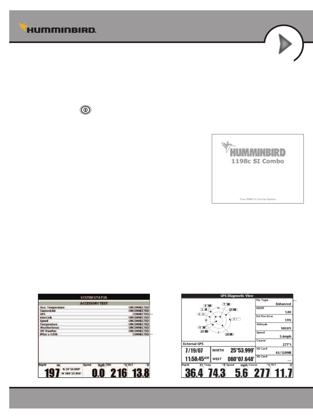
VERIFYING INSTALLATION AND SYSTEM STARTUP
OF THE HUMMINBIRD
All equipment should be connected and powered before you turn on the Humminbird. When the i-Pilot Link is
detected,
i-Pilot Link Connected
will display briefly on the Humminbird screen. You can also confirm the installation
connections using the following instructions.
1. Press the POWER/LIGHT key on the Humminbird. If you are powering on a Humminbird in a
multiple-Humminbird Ethernet network, power on the
Humminbird that is connected to the i-Pilot Link first.
2. When the Title screen is displayed, press the MENU key to open
the Start-Up Options Menu.
3. Use the 4-WAY Cursor Control key to select Normal, and press
the RIGHT Cursor key.
4. Press and hold the VIEW key. Select System > Accessory Test.
Confirm that i-Pilot Link is listed as Connected. It may take a
minute for the equipment to be detected.
5. Press and hold the VIEW key. Select System > GPS Diagnostic View. Confirm that External GPS is displayed
and the Fix Type indicates Enhanced or 3D.
NOTE: A GPS Receiver is required to enable the navigation features on the Humminbird. The Humminbird uses the
data from the GPS Receiver attached directly to it or within the Ethernet network.
NOTE: If the GPS Diagnostic View or Accessory Test is not displayed in the View Rotation, press the MENU key
twice to open the Main Menu. Select the Views tab > GPS Diagnostic View or Accessory Test. Change the setting
for each view to Visible.
Confirming the GPS Fix Type
Fix Type
should be
3D or
Enhanced
Confirming that i-Pilot Link is Detected
i-Pilot Link
listed as
connected
GPS listed as
connected
Title Screen
26
minnkotamotors.com
GETTING STARTED
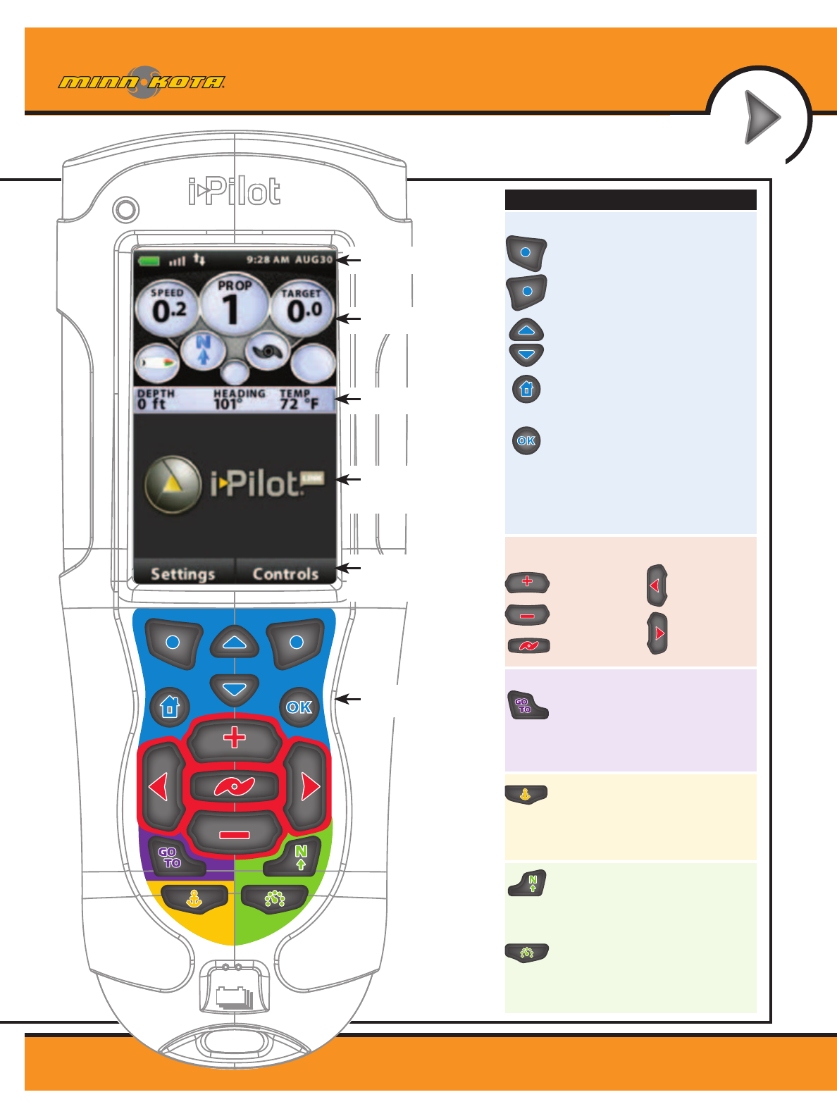
KNOWING YOUR REMOTE
Remote Layout
See diagram to the right.
Power
To turn the remote
on, press the OK key.
To turn the remote off, press
and hold the OK key or select
Home>Settings>Off –OK
Construction
The remote is waterproof and
floats in water.
Range
The range of the remote will be
greatly reduced if it is used near
or mounted to any metal object
including aluminum or steel.
It is also recommended that the
front end of the remote not be
obstructed during use.
MENU CONTROL KEYS
Left Softkey & Right Softkey
These keys change function based on mode
of operation and which screen is presently
displayed. The Softkey Labels at the bottom
of the LCD indicate their current function.
Menu Up & Menu Down
Used to navigate the menus.
Home
Pressing this key will always bring up the
Home Screen.
OK
Press to accept menu selections.
Remote power:
• Pressandreleasetoturntheremoteon.
• Pressandholdfor3secondstoturnthe
remote off.
MANUAL CONTROL KEYS
Speed Up
Speed Down
Prop On/Off
Auto Pilot
Press to enable AutoPilot or
Advanced AutoPilot.
The default mode is selected through the
Controls Menu on the remote.
Cruise Control
Press to bring up the Cruise Control
Access screen. Target speed is adjusted
using the + and – keys and accepted using
the OK key.
GOTO
Opens the list of iTracks, Spot-Locks and
Waypoints that are within navigable range.
Also used to switch from the Home Screen
to the Active Screen during i-Pilot navigation.
Spot-Lock
Press to enable Spot-Lock.
Press and hold to mark a Waypoint
on the Humminbird (Spot-Lock will
not engage).
NAVIGATION KEYS
HEADER
DASHBOARD
INFO BOXES
CONTENT
AREA
SOFTKEY
LABELS
KEYPAD
KEYPAD
DASHBOARD
HEADER
QUICK REFERENCE
GUIDE
Steer Left
Steer Right
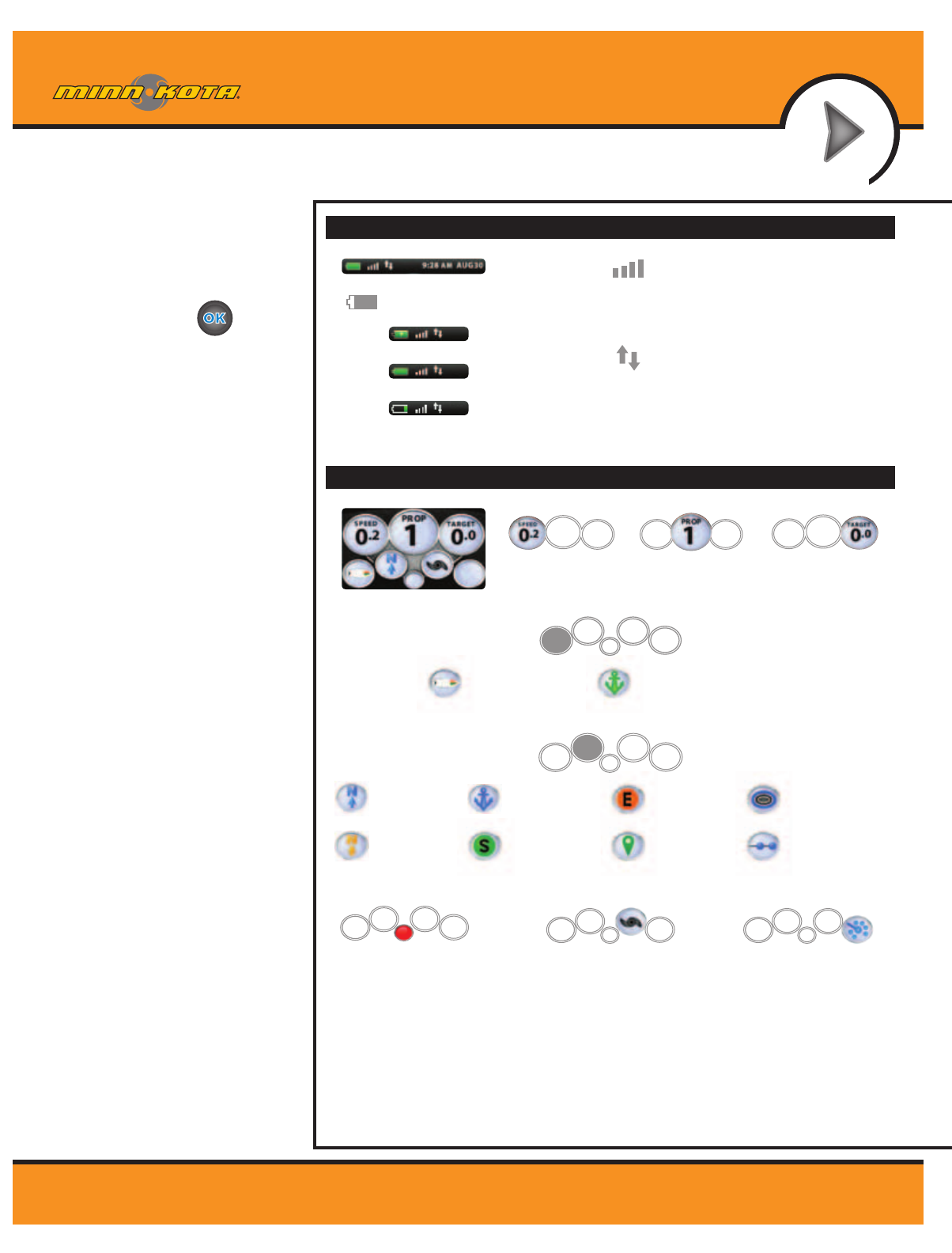
State-of-Charge indicator
for the remote battery.
GPS Signal Strength
Flashing indicates no GPS fix.
Humminbird Connection
Highlights when the i-Pilot controller is in
communications with the Humminbird.
When there are no communications,
the arrows turn gray.
Time and Date
This data is provided by the GPS.
12:1
3 PM OCT 18
12:13 PM OCT
18
Recording an iTrack
When the red dot is shown, it
indicates that Link is currently
recording an iTrack.
Legacy
AutoPilot
Advanced
AutoPilot
Cruise Control
Target Speed
Navigation Mode
Motor Speed
Cruise Control
When the icon is shown,
the Cruise Control feature
is enabled.
Spot-Lock
Navigating
to Start
Navigating
to End
Navigating
to Waypoint
Following a
Contour
Navigating
a Route
Spot-Lock Paused
Prop Status
The states of the prop icon are:
• Propiconisnoton=propisdisabled.
• Onsteadybutnotrotating=propis
enabled but the prop speed is zero.
• Rotating=propisenabledandspeed
is greater than zero.
• Blinking=propisdisabledbutLinkis
in a mode of navigation and the user is
being reminded to enable the prop.
GPS Speed
Charging Battery
Full Battery
Low Battery
2377155 Revision B
27
minnkotamotors.com
GETTING STARTED
MENU CONTROL KEYS
Left Softkey & Right Softkey
These keys change function based on mode
of operation and which screen is presently
displayed. The Softkey Labels at the bottom
of the LCD indicate their current function.
Menu Up & Menu Down
Used to navigate the menus.
Home
Pressing this key will always bring up the
Home Screen.
OK
Press to accept menu selections.
Remote power:
• Pressandreleasetoturntheremoteon.
• Pressandholdfor3secondstoturnthe
remote off.
MANUAL CONTROL KEYS
Speed Up
Speed Down
Prop On/Off
Auto Pilot
Press to enable AutoPilot or
Advanced AutoPilot.
The default mode is selected through the
Controls Menu on the remote.
Cruise Control
Press to bring up the Cruise Control
Access screen. Target speed is adjusted
using the + and – keys and accepted using
the OK key.
GOTO
Opens the list of iTracks, Spot-Locks and
Waypoints that are within navigable range.
Also used to switch from the Home Screen
to the Active Screen during i-Pilot navigation.
Spot-Lock
Press to enable Spot-Lock.
Press and hold to mark a Waypoint
on the Humminbird (Spot-Lock will
not engage).
NAVIGATION KEYS
HEADER
DASHBOARD
INFO BOXES
CONTENT
AREA
SOFTKEY
LABELS
KEYPAD
KEYPAD
DASHBOARD
HEADER
QUICK REFERENCE
GUIDE
Steer Left
Steer Right
State-of-Charge indicator
for the remote battery.
GPS Signal Strength
Flashing indicates no GPS fix.
Humminbird Connection
Highlights when the i-Pilot controller is in
communications with the Humminbird.
When there are no communications,
the arrows turn gray.
Time and Date
This data is provided by the GPS.
12:1
3 PM OCT 18
12:13 PM OCT
18
Recording an iTrack
When the red dot is shown, it
indicates that Link is currently
recording an iTrack.
Legacy
AutoPilot
Advanced
AutoPilot
Cruise Control
Target Speed
Navigation Mode
Motor Speed
Cruise Control
When the icon is shown,
the Cruise Control feature
is enabled.
Spot-Lock
Navigating
to Start
Navigating
to End
Navigating
to Waypoint
Following a
Contour
Navigating
a Route
Spot-Lock Paused
Prop Status
The states of the prop icon are:
• Propiconisnoton=propisdisabled.
• Onsteadybutnotrotating=propis
enabled but the prop speed is zero.
• Rotating=propisenabledandspeed
is greater than zero.
• Blinking=propisdisabledbutLinkis
in a mode of navigation and the user is
being reminded to enable the prop.
GPS Speed
Charging Battery
Full Battery
Low Battery
2377155 Revision B
28
minnkotamotors.com
GETTING STARTED
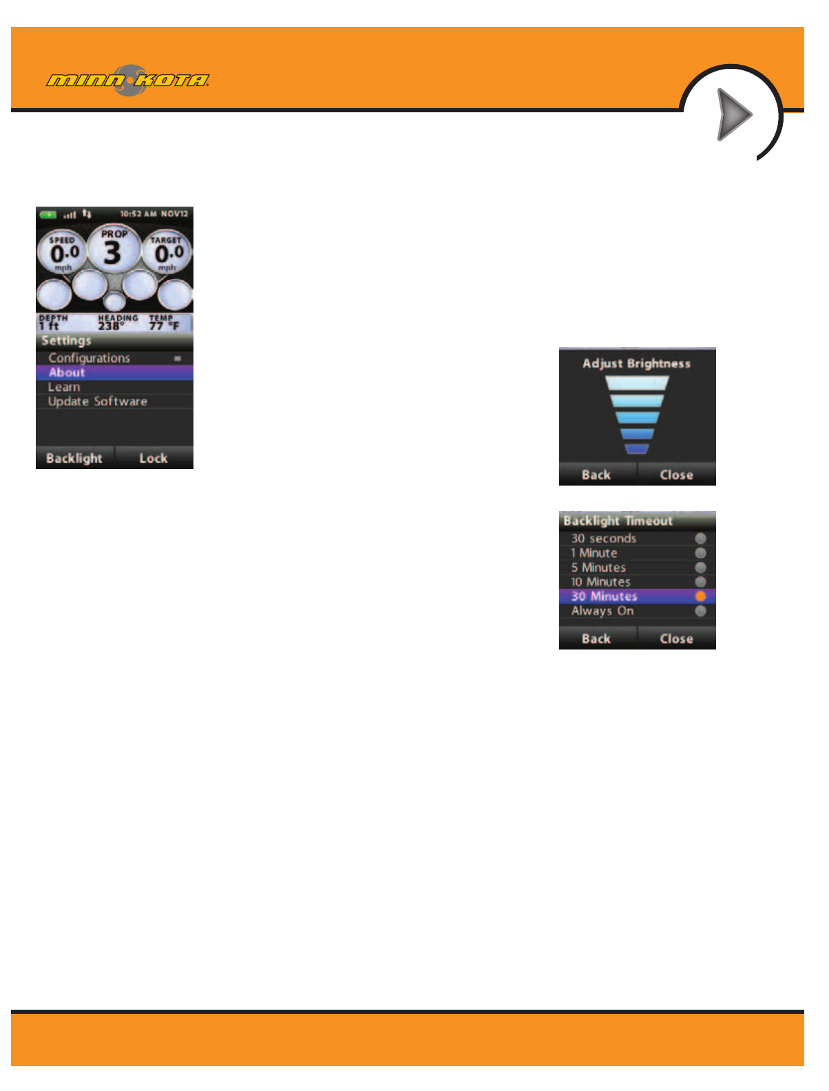
Backlight Settings:
Settings Menu>Backlight Softkey
Backlight Settings>Brightness
This screen allows the user to manually control
the brightness of the backlight. Use the up/
down arrow keys to adjust. Select the Back or
Close Softkey to save the setting and exit.
Backlight Settings>Timeout
The selections on this screen control how long
the backlight will stay on after the last key press.
Use the up/down arrow keys to select a new
value and press the OK key to accept.
Settings menu
SETTINGS MENU
To enter the Settings Menu, select Home>Settings Softkey
29
minnkotamotors.com
GETTING STARTED
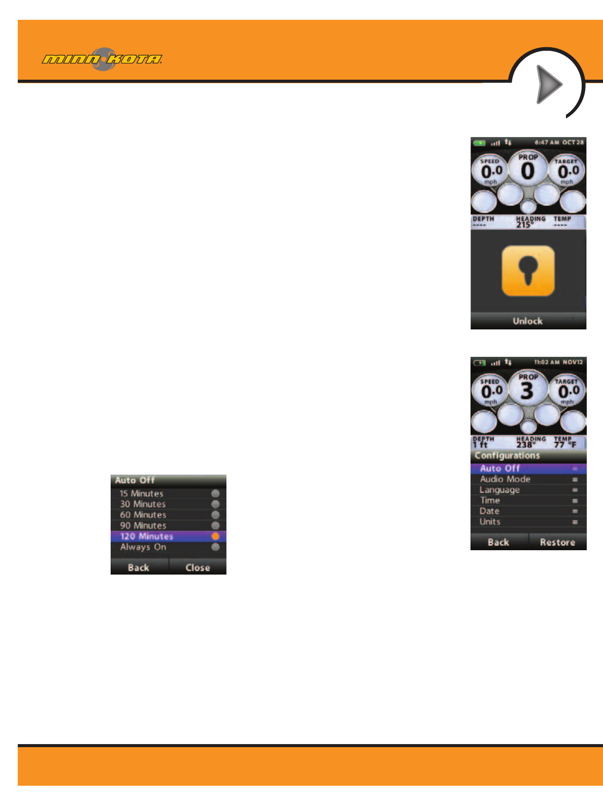
Keypad Lock:
To lock the keypad: From the Settings menu, press and hold the Lock Softkey.
To Unlock the keypad: Press and hold either Unlock Softkey.
Settings:
Settings>Configurations
Configurations menu
Enter this menu by selecting Home>Settings Softkey> Configurations -> OK
Configurations>Restore Softkey
This selection allows the user to reset the configurations on the remote to
factory defaults.
Configurations>Auto Off
The selections on this menu control how long
after the last key press the remote will
automatically shut off. Use the up/down arrow
keys to select a new value and press the OK key
to accept. Select the Back or Close Softkey to
save the setting and exit.
Configurations>Audio Mode
a. The selections on this menu control how long after the last key press the
remote will automatically shut off. Use the up/down arrow keys to select
a new value and press the OK key to accept. Select the Back or Close
softkey to save the setting and exit.
b. Refer to the Audio Modes section of the manual for further details.
Keypad Lock
Settings>Configurations
30
minnkotamotors.com
GETTING STARTED
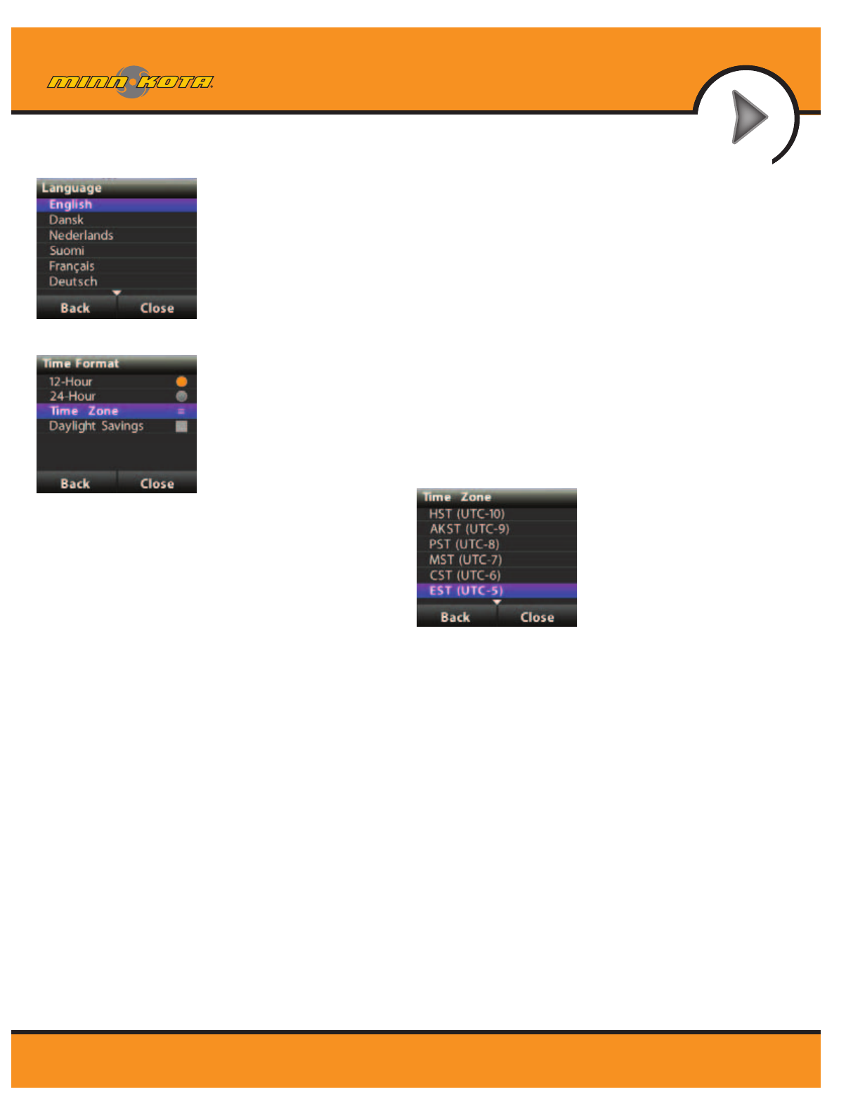
Configurations>Language
From this menu, the user has the option of changing the language of the text
that appears on the remote screen. Use the up/down arrow keys to select a
new language and press the OK key to accept the setting and exit the menu.
Or, select the Back or Close Softkey to exit without making changes.
Configurations>Time
From this menu, the user configures the following:
a. 12-hour/24-hour: This controls the format that the time appears in on
the screen header. Use the up/down arrow keys to select the desired
format a new value and press the OK key to accept. Select the Back or
Close Softkey to save the setting and exit.
b. Time Zone: Choosing this
selection will bring up a list
of time zones.
c. Daylight Savings: This checkbox is used to configure the Link remote and
controller to account for Daylight Savings Time. Highlight this checkbox
and use the OK key to enable/disable the feature and select the Back or
Close Softkey to exit the screen.
Configurations>Language
Configurations>Time
31
minnkotamotors.com
GETTING STARTED
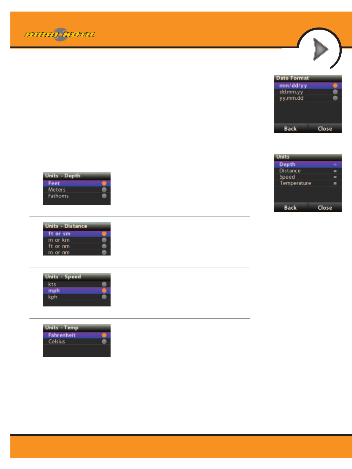
Configurations>Date
From this menu, the user configures the format that the date appears on GOTO screen
on remote. Use the up/down arrow keys to select a new value and press the OK key
to accept. Select the Back or Close Softkey to save the setting and exit.
Configurations>Units
From this menu, the user configures the following:
a. Depth: Choosing this selection will bring up
a list of units to use when displaying depth.
Use the up/down arrow keys to select a new value
and press the OK key to accept. Select the Back or
Close Softkey to save the setting and exit.
b. Distance: Choosing this selection will bring up
a list of units to use when displaying distance.
Use the up/down arrow keys to select a new value
and press the OK key to accept. Select the Back or
Close Softkey to save the setting and exit.
c. Speed: Choosing this selection will bring up
a list of units to use when displaying speed.
Use the up/down arrow keys to select a new value
and press the OK key to accept. Select the Back or
Close Softkey to save the setting and exit.
d. Temperature: Choosing this selection will bring up a
list of units to use when displaying temperature.
Use the up/down arrow keys to select a new value
and press the OK key to accept. Select the Back or
Close Softkey to save the setting and exit.
Settings>About
Displays the current revisions of software for the remote and the controller
Settings>Learn
Used during the process of learning the remote to a controller (see details on page 31)
Settings>Update Software
Used to check for and initiate software updates for the remote. See details in the Software Update section.
Configurations>Units
Configurations>Date
32
minnkotamotors.com
GETTING STARTED
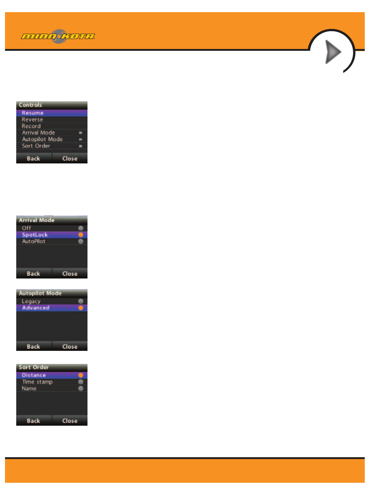
Controls>Resume
When navigation is paused (Spot-Locked), selecting Resume will restart the original
navigation mode. Note that this selection is only available when navigation is
currently paused.
Controls>Reverse
While navigating an iTrack or contour line, selecting Reverse will change the
direction of travel. Note that this selection is only available while navigating these
types of features.
Controls>Record
Select Record to begin recording an iTrack. This selection is also used to return to
the Record Active screen if a recording is in process and the user has brought up a
different screen.
Controls>Arrival Mode
The selections on this menu are used to tell i-Pilot Link what to do when a destination
is reached during certain types of navigation. Use the up/down arrow keys to select
the setting and press the OK key to accept. Select the Back or Close softkey to save
the setting and exit.
a. This same configuration is accessible through the Humminbird.
Controls>Autopilot Mode
From this menu the user configures which version of AutoPilot to use when
AutoPilot is engaged. Use the up/down arrow keys to select the setting and press
the OK key to accept. Select the Back or Close Softkey to save the setting and exit.
a. This same configuration is accessible through the Humminbird.
Controls>Sort Order
The selections on this menu control the order in which navigational points appear on
the GoTo screen. Use the up/down arrow keys to select a new value and press the
OK key to accept. Select the Back or Close softkey to save the setting and exit.
Controls Menu
Controls>Arrival Mode
Controls>Autopilot Mode
CONTROLS MENU
To enter the Controls Menu, select Home>Controls Softkey
Controls>Sort Order
33
minnkotamotors.com
GETTING STARTED
i-Pilot Link
Speaker
Remote Learn
Button
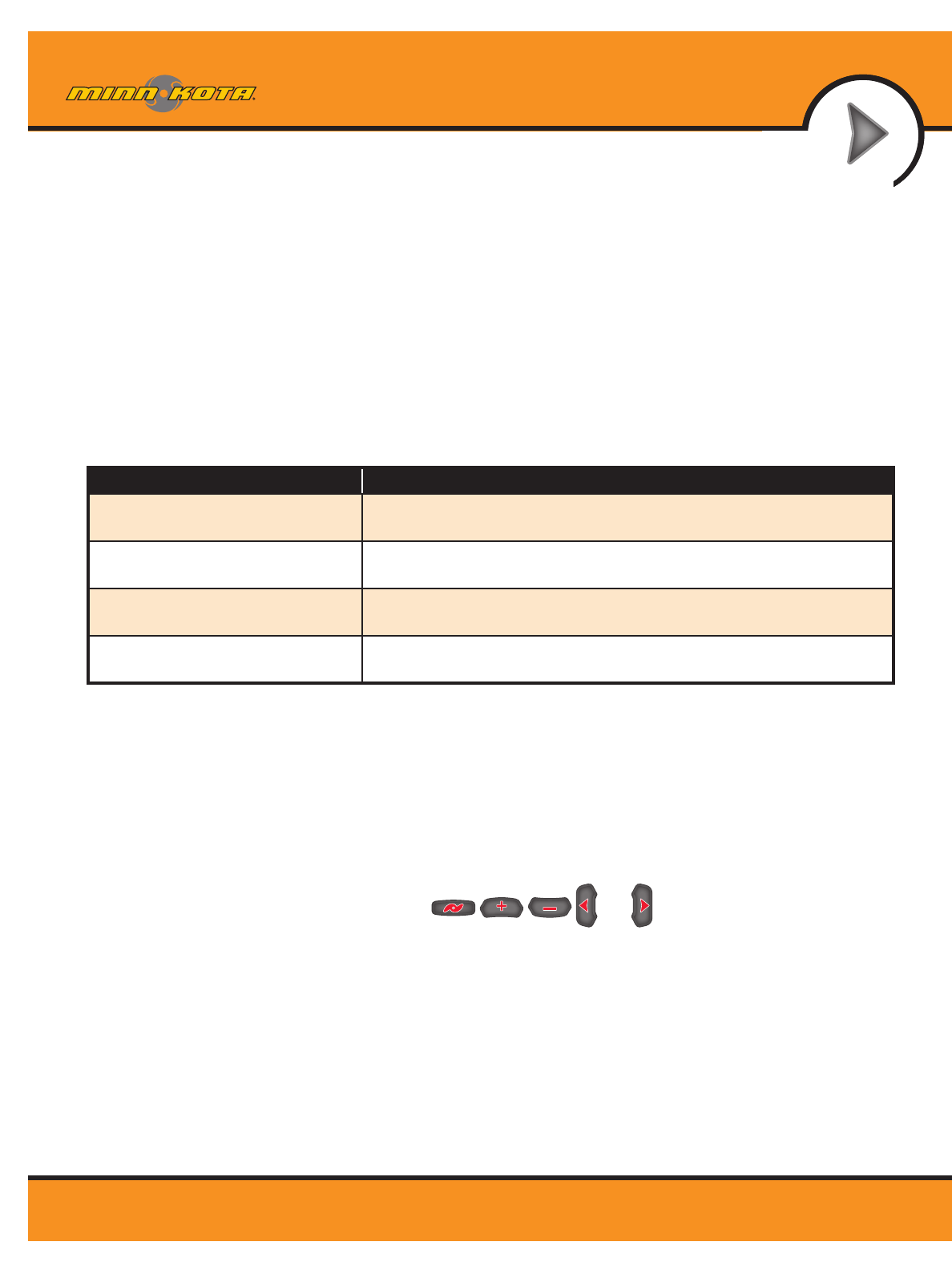
KNOWING YOUR I-PILOT LINK CONTROLLER
Construction
The i-Pilot Link controller contains a very sensitive digital compass and is where all GPS
satellite and i-Pilot Link remote signals are received. It is very important that the controller
have a clear view of the sky in all directions and has a clear line of sight to the remote for
optimum performance. All electronics within the controller enclosure are completely sealed.
Remote Learning
The i-Pilot Link remote is prelearned to the controller from the factory. The top of
the controller has a single learn button to allow additional remotes to be added
to the system. To learn additional remotes:
1. Power up the trolling motor.
2. Push and hold the learn button down. A steady audio tone will
be heard while holding this button.
3. While holding the learn button on the controller, from the remote home screen select:
Settings>Learn and press the OK key
4. If the learn process was successful, the controller will respond with four beeps. In
addition, the Dashboard section of the remote will begin to display motor status
information such as prop speed.
A remote can only be learned to one controller at a time. A controller can have up to
4 remotes learned to it and actively communicating with it.
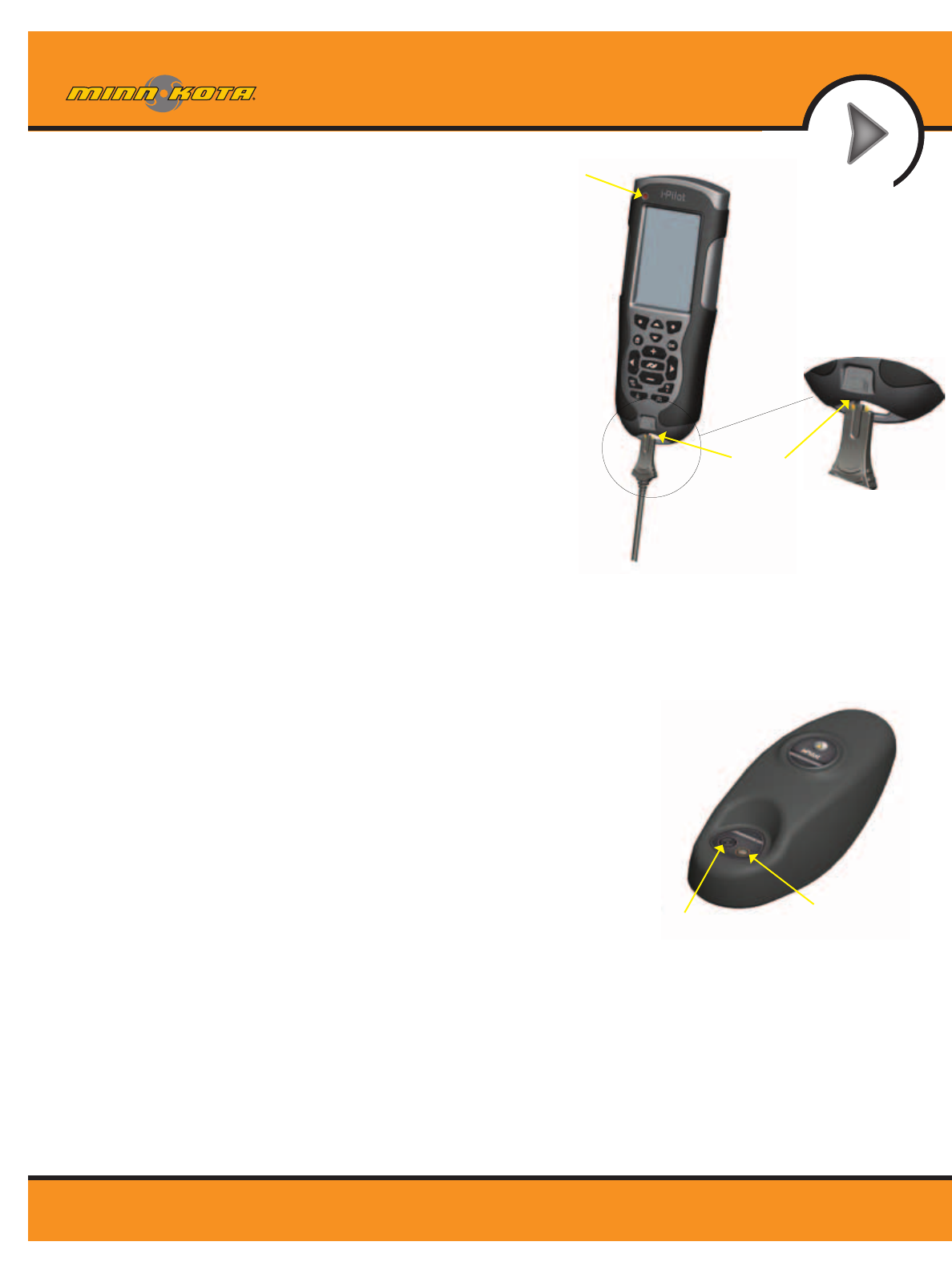
The i-Pilot Link remote contains a rechargeable battery. To charge the
battery, plug the USB end into the included AC adapter and plug the
other (two pronged) end into the charging port of the remote
(reference graphic). The Charging Indicator will illuminate whenever
an energized charging cable is connected.
The user also has the option of plugging the USB end of the charging
cable into any USB type power source. The remote can be recharged
while the remote is on or off.
Note: the USB end of the charging cable is not intended for
prolonged exposure to saltwater environments.
REMOTE BATTERY
Charging
Port
Charging
Indicator

34
minnkotamotors.com
GETTING STARTED
Audio Modes
The i-Pilot Link Controller also contains an internal speaker which can be programmed to work in two different
audio modes. The speaker is programmed to operate in audio mode one from the factory. To select the
different audio modes, from the Home screen go to: Settings>Configurations>Audio Mode. For an
explanation of each audio mode and their sounds see the table below.
35
minnkotamotors.com
GETTING STARTED
Power
The i-Pilot Link controller will turn on whenever the trolling motor has power. For Terrova and Riptide ST
motors this is when the green system ready light is on. For PowerDrive V2 and Riptide SP motors this is
whenever the motor is connected to power.
* For this reason it is very important to disconnect a PowerDrive V2 or Riptide SP motor from power when not in
use or battery drain will occur.
Accuracy
The accuracy and responsiveness with which i-Pilot Link controls your boat is highly dependent upon many variables.
Just a few of these variables and their general effects on responsiveness and accuracy are given below so that the
behavior of the system can be understood.
System Startup
Once you have verified i-Pilot Link’s installation it’s time to start using it on the water. Follow these simple steps
each time you power up your trolling motor for successful operation:
1. Connect trolling motor to power.
2. Deploy trolling motor into water.
3 Turn the remote on by pressing the OK key. Verify the Dashboard section of the screen shows all motor
status information.
4. You are now able to use all manual functions: and .
5. After i-Pilot Link has obtained a minimum GPS signal strength of one bar, all remaining functions will
become available.
VARIABLE EFFECT
Ratio of motor thrust to boat weight Excessive thrust on a smaller boat can cause i-Pilot Link to overcorrect.
Not enough thrust on a large boat can cause i-Pilot Link to respond slowly.
Wind Excessive wind and/or current can reduce i-Pilot Link’s
positioning accuracy.
GPS signal strength The greater number of GPS signal bars the greater
the accuracy.
Trolling motor battery power level A fully charged battery will give the best performance.

36
minnkotamotors.com
GETTING STARTED
HUMMINBIRD SOFTWARE UPDATES
Set up an online account at humminbird.com so that you will receive the latest Humminbird news and software
updates for your Fishing System. The i-Pilot Link software can also be updated through the control head.
WARNING! Humminbird® is not responsible for the loss of data files (waypoints, routes, tracks, groups,
snapshots, recordings, etc.) that may occur due to direct or indirect damage to the unit’s hardware or
software. It is important to back up your control head’s data files periodically. Data files should also be
saved to your PC before restoring the unit’s defaults or updating the software. See your Humminbird
®
online account at humminbird.com and the Waypoint Management guide.
Required Equipment: Personal computer with Internet access, a formatted SD memory card, and a USB
Memory Card Reader.
Update the Software
1. Install a formatted SD memory card into the card reader connected to your PC.
2. Register your Fishing System: Log on to humminbird.com. Click My Account. Set up a new account or log
into your current account and add the i-Pilot Link to your My Equipment tab.
3. Download: From My Account\My Profile\My Equipment, click the file name of the latest software update
(unit name [version #]) for your control head.
• Read the instructions in the dialog box and click Download.
• Follow the on-screen instructions to save the software les directly to the SD Card.
4. Repeat step 3 to download the i-Pilot Link controller and remote software files.
5. Install the SD card with the updated software files into the control head card slot.
6. Power on your Fishing System.
7. Control Head Update: The control head will recognize the new software. Follow the dialog box
instructions to confirm software installation.
i-Pilot Link: The software will be updated automatically. It may take up to two minutes for the software to
be detected on the network, and the control head will display on-screen dialog boxes to indicate that the
update is in progress.
NOTE: To purchase the USB Memory Card Reader (AS CR), visit our Web site at humminbird.com or
contact our Customer Resource Center at 1-800-633-1468. Our Customer Resource Center will also assist
you with any questions you might have about updating your Humminbird
®
Fishing System.
8. After the software download is complete, you will need to cycle power to the trolling motor to regain
proper motor control.