Johnson Outdoors ULTERRAIP20 Bow-Mount Trolling Motor User Manual Rev 2
Johnson Outdoors, Inc. Bow-Mount Trolling Motor Users Manual Rev 2
Users Manual Rev 2
ULTERRA
BOW-MOUNT TROLLING MOTOR
OWNER'S MANUAL
Model: _________________________________________________________________________________________________________________________
Serial Number: _______________________________________________________________________________________________________________
Purchase Date: _______________________________________________________________________________________________________________
Store Where Purchased: ____________________________________________________________________________________________________
NOTE: Do not return your Minn Kota motor to your retailer. Your retailer is not authorized to repair or replace this unit. You may obtain service
by: calling Minn Kota at (800) 227-6433; returning your motor to the Minn Kota Factory Service Center; sending or taking your motor to any
Minn Kota authorized service center. A list of authorized service centers is available on our website, at minnkotamotors.com. Please include proof of
purchase, serial number and purchase date for warranty service with any of the above options.
Please thoroughly read this user manual. Follow all instructions and heed all safety and cautionary notices below. Use of this motor is only
permitted for persons that have read and understood these user instructions. Minors may use this motor only under adult supervision.
ATTENTION: Never run the motor out of the water, as this may result in injuries from the rotating propeller. The motor should be disconnected from
the power source when it is not in use or is off the water. When connecting the power-supply cables of the motor to the battery, ensure that they are
not kinked or subject to chafe and route them in such a way that persons cannot trip over them. Before using the motor make sure that the insulation
of the power cables is not damaged. Disregarding these safety precautions may result in electric shorts of battery(s) and/or motor. Always disconnect
motor from battery(s) before cleaning or checking the propeller. Avoid submerging the complete motor as water may enter the lower unit through
control head and shaft. If the motor is used while water is present in the lower unit considerable damage to the motor can occur. This damage will not
be covered by warranty.
CAUTION: Take care that neither you nor other persons approach the turning propeller too closely, neither with body parts nor with objects. The
motor is powerful and may endanger or injure you or others. While the motor is running watch out for persons swimming and for fl oating objects.
Persons whose ability to run the motor or whose reactions are impaired by alcohol, drugs, medication, or other substances are not permitted to use
this motor. This motor is not suitable for use in strong currents. The constant noise pressure level of the motor during use is less than 70dB(A). The
overall vibration level does not exceed 2,5m/sec2.
THAnK YoU
Thank you for choosing Minn Kota. We believe that you should spend more time fi shing and less time positioning your boat.
That’s why we build the smartest, toughest, most intuitive trolling motors on the water. Every aspect of a Minn Kota trolling motor
is thought out and rethought until it’s good enough to bear our name. Countless hours of research and testing provide you the
Minn Kota advantage that can truly take you “Anywhere. Anytime.” We don’t believe in shortcuts. We are Minn Kota. And we are
never done helping you catch more fi sh.
REMEMBER TO KEEP YOUR RECEIPT AND IMMEDIATELY REGISTER YOUR TROLLING MOTOR.
A registration card is enclosed or you can complete registration on the internet at minnkotamotors.com.
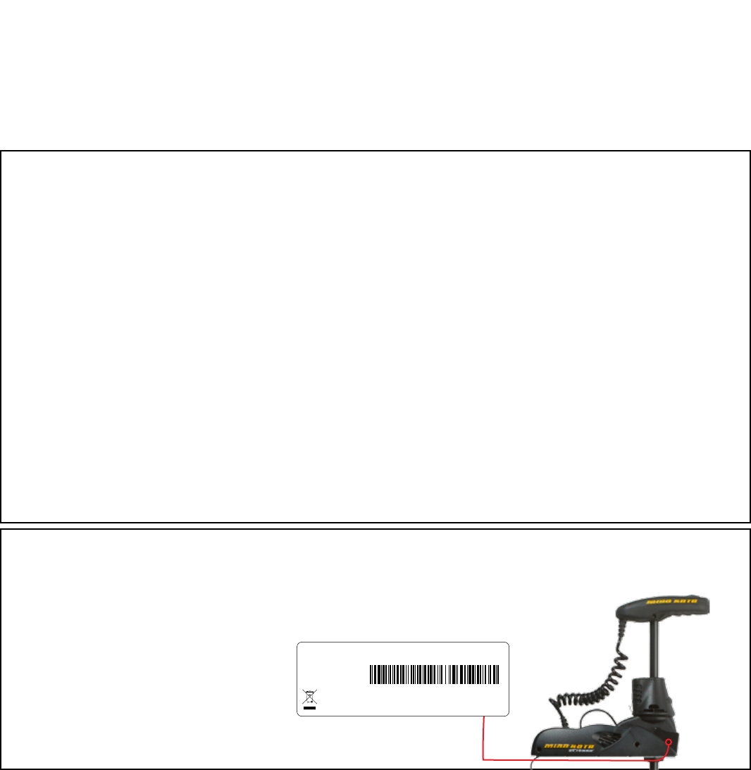
LOCATING YOUR SERIAL NUMBER
Your Minn Kota 11-character serial number is very important. It helps to determine the specifi c model and year of manufacture. When contacting
Consumer Service or registering your product, you will need to know your product’s serial number. We recommend that you write the serial number
down in the space provided below so that you have it available for future reference.
CE MASTER USER MANUAL (FOR CE/C-TICK CERTIFIED MODELS)
Conforms to 89/336/EEC (EMC) under standards EN 55022A, EN 50082-2 since 1996 LN V9677264
Model: _________________________________________________________________________________________________________________________
Serial Number: _______________________________________________________________________________________________________________
Purchase Date: _______________________________________________________________________________________________________________
Store Where Purchased: ____________________________________________________________________________________________________
NOTE: Do not return your Minn Kota motor to your retailer. Your retailer is not authorized to repair or replace this unit. You may obtain service
by: calling Minn Kota at (800) 227-6433; returning your motor to the Minn Kota Factory Service Center; sending or taking your motor to any
Minn Kota authorized service center. A list of authorized service centers is available on our website, at minnkotamotors.com. Please include proof of
purchase, serial number and purchase date for warranty service with any of the above options.
Please thoroughly read this user manual. Follow all instructions and heed all safety and cautionary notices below. Use of this motor is only
permitted for persons that have read and understood these user instructions. Minors may use this motor only under adult supervision.
ATTENTION: Never run the motor out of the water, as this may result in injuries from the rotating propeller. The motor should be disconnected from
the power source when it is not in use or is off the water. When connecting the power-supply cables of the motor to the battery, ensure that they are
not kinked or subject to chafe and route them in such a way that persons cannot trip over them. Before using the motor make sure that the insulation
of the power cables is not damaged. Disregarding these safety precautions may result in electric shorts of battery(s) and/or motor. Always disconnect
motor from battery(s) before cleaning or checking the propeller. Avoid submerging the complete motor as water may enter the lower unit through
control head and shaft. If the motor is used while water is present in the lower unit considerable damage to the motor can occur. This damage will not
be covered by warranty.
CAUTION: Take care that neither you nor other persons approach the turning propeller too closely, neither with body parts nor with objects. The
motor is powerful and may endanger or injure you or others. While the motor is running watch out for persons swimming and for fl oating objects.
Persons whose ability to run the motor or whose reactions are impaired by alcohol, drugs, medication, or other substances are not permitted to use
this motor. This motor is not suitable for use in strong currents. The constant noise pressure level of the motor during use is less than 70dB(A). The
overall vibration level does not exceed 2,5m/sec2.
THAnK YoU
Thank you for choosing Minn Kota. We believe that you should spend more time fi shing and less time positioning your boat.
That’s why we build the smartest, toughest, most intuitive trolling motors on the water. Every aspect of a Minn Kota trolling motor
is thought out and rethought until it’s good enough to bear our name. Countless hours of research and testing provide you the
Minn Kota advantage that can truly take you “Anywhere. Anytime.” We don’t believe in shortcuts. We are Minn Kota. And we are
never done helping you catch more fi sh.
REMEMBER TO KEEP YOUR RECEIPT AND IMMEDIATELY REGISTER YOUR TROLLING MOTOR.
A registration card is enclosed or you can complete registration on the internet at minnkotamotors.com.
LOCATING YOUR SERIAL NUMBER
Your Minn Kota 11-character serial number is very important. It helps to determine the specifi c model and year of manufacture. When contacting
Consumer Service or registering your product, you will need to know your product’s serial number. We recommend that you write the serial number
down in the space provided below so that you have it available for future reference.
CE MASTER USER MANUAL (FOR CE/C-TICK CERTIFIED MODELS)
Conforms to 89/336/EEC (EMC) under standards EN 55022A, EN 50082-2 since 1996 LN V9677264
Thank you for purchasing the Minn Kota Ulterra electric steer trolling motor. This motor provides the ultimate hands-off
operation by giving the user automatic stow and deploy and powered trim as well as all the other MinnKota electric steer motor
features that users have grown to love. The simplicity of use maximizes your time on the water and ensures you spend your time
fishing. By following the instructions provided in this manual, you will learn how to properly install and operate your new Ulterrra
for years of trouble free use. We encourage you to read this manual thoroughly in order to maximize your product experience.
2 | minnkotamotors.com ©2014 Johnson Outdoors Marine Electronics, Inc.
Model: _________________________________________________________________________________________________________________________
Serial Number: _______________________________________________________________________________________________________________
Purchase Date: _______________________________________________________________________________________________________________
Store Where Purchased: ____________________________________________________________________________________________________
NOTE: Do not return your Minn Kota motor to your retailer. Your retailer is not authorized to repair or replace this unit. You may obtain service
by: calling Minn Kota at (800) 227-6433; returning your motor to the Minn Kota Factory Service Center; sending or taking your motor to any
Minn Kota authorized service center. A list of authorized service centers is available on our website, at minnkotamotors.com. Please include proof of
purchase, serial number and purchase date for warranty service with any of the above options.
Please thoroughly read this user manual. Follow all instructions and heed all safety and cautionary notices below. Use of this motor is only
permitted for persons that have read and understood these user instructions. Minors may use this motor only under adult supervision.
ATTENTION: Never run the motor out of the water, as this may result in injuries from the rotating propeller. The motor should be disconnected from
the power source when it is not in use or is off the water. When connecting the power-supply cables of the motor to the battery, ensure that they are
not kinked or subject to chafe and route them in such a way that persons cannot trip over them. Before using the motor make sure that the insulation
of the power cables is not damaged. Disregarding these safety precautions may result in electric shorts of battery(s) and/or motor. Always disconnect
motor from battery(s) before cleaning or checking the propeller. Avoid submerging the complete motor as water may enter the lower unit through
control head and shaft. If the motor is used while water is present in the lower unit considerable damage to the motor can occur. This damage will not
be covered by warranty.
CAUTION: Take care that neither you nor other persons approach the turning propeller too closely, neither with body parts nor with objects. The
motor is powerful and may endanger or injure you or others. While the motor is running watch out for persons swimming and for fl oating objects.
Persons whose ability to run the motor or whose reactions are impaired by alcohol, drugs, medication, or other substances are not permitted to use
this motor. This motor is not suitable for use in strong currents. The constant noise pressure level of the motor during use is less than 70dB(A). The
overall vibration level does not exceed 2,5m/sec2.
THAnK YoU
Thank you for choosing Minn Kota. We believe that you should spend more time fi shing and less time positioning your boat.
That’s why we build the smartest, toughest, most intuitive trolling motors on the water. Every aspect of a Minn Kota trolling motor
is thought out and rethought until it’s good enough to bear our name. Countless hours of research and testing provide you the
Minn Kota advantage that can truly take you “Anywhere. Anytime.” We don’t believe in shortcuts. We are Minn Kota. And we are
never done helping you catch more fi sh.
REMEMBER TO KEEP YOUR RECEIPT AND IMMEDIATELY REGISTER YOUR TROLLING MOTOR.
A registration card is enclosed or you can complete registration on the internet at minnkotamotors.com.
LOCATING YOUR SERIAL NUMBER
Your Minn Kota 11-character serial number is very important. It helps to determine the specifi c model and year of manufacture. When contacting
Consumer Service or registering your product, you will need to know your product’s serial number. We recommend that you write the serial number
down in the space provided below so that you have it available for future reference.
CE MASTER USER MANUAL (FOR CE/C-TICK CERTIFIED MODELS)
Conforms to 89/336/EEC (EMC) under standards EN 55022A, EN 50082-2 since 1996 LN V9677264
Made by Minn Kota
Johnson Outdoors
Marine Electronics, Inc.
121 Power Drive
Mankato, MN 56001 USA
Trolling Motors
Produced in 2012
Ulterra 80 60”
MODEL 1358901
SER NO M365 MK12345
The serial number on your Ulterra is located
inside the mount near the motor rests.
EXAMPLE
You are responsible for the safe and prudent operation of your vessel. We have designed i-Pilot to be an accurate and reliable tool that will enhance boat
operation and improve your ability to catch fish. This product does not relieve you from the responsibility for safe operation of your boat. You must avoid
hazards to navigation and always maintain a permanent watch so you can respond to situations as they develop. You must always be prepared to regain
manual control of your boat. Learn to operate your i-Pilot in an area free from hazards and obstacles.

minnkotamotors.com | 3
©2014 Johnson Outdoors Marine Electronics, Inc.
TAbLE of ConTEnTs
Two-Year Limited Warranty 4-5
Warranty on Minn Kota i-Pilot® and i-Pilot® Link™ Wireless GPS Trolling System 8
Warranty on Minn Kota Freshwater Trolling Motors 8
Introduction 5
Features 5
Mount Installation 6-7
Battery & Wiring Installation 8-9
Boat Rigging & Product Installation 8
Conductor Gauge and Circuit Breaker Sizing Table 8
Selecting the Correct Batteries 9
How to Connect Batteries 9
Motor Wiring Diagram 10
Using & Adjusting The Motor 11-13
Stowing & Deploying the Motor 11
Adjusting the Depth of the Motor 12
Adjusting the Steering Cable 12
Controlling Speed and Steering with the Foot Pedal 13
Service & Maintenance 14
Propeller Replacement 14
General Maintenance 14
Troubleshooting & Repair 15
Parts Diagram 16
Parts List 17
Environmental Compliance Statement 18
Notes 19

wARRAnTY on minn KoTA i-PiLoT® And i-PiLoT® LinK™ wiRELEss gPs TRoLLing
sYsTEm ACCEssoRY
Johnson Outdoors Marine Electronics, Inc. (“JOME”) extends the following limited warranty to the original retail purchaser only. Warranty coverage is not
transferable.
minn KoTA LimiTEd Two-YEAR wARRAnTY on THE EnTiRE PRodUCT
JOME warrants to the original retail purchaser only that the purchaser’s new Minn Kota i-Pilot® or i-Pilot® Link™ Wireless GPS Trolling System Accessory will
be materially free from defects in materials and workmanship appearing within two (2) years after the date of purchase. JOME will (at its option) either repair
or replace, free of charge, any parts found by JOME to be defective during the term of this warranty. Such repair, or replacement shall be the sole and exclusive
liability of JOME and the sole and exclusive remedy of the purchaser for breach of this warranty.
EXCLUsions And LimiTATions
This limited warranty does not apply to products that have been used commercially or for rental purposes. This limited warranty does not cover normal
wear and tear, blemishes that do not aff ect the operation of the product, or damage caused by accidents, abuse, alteration, modifi cation, shipping
damages, acts of God, negligence of the user or misuse, improper or insuffi cient care or maintenance. DAMAGE CAUSED BY THE USE OF OTHER
REPLACEMENT PARTS NOT MEETING THE DESIGN SPECIFICATIONS OF THE ORIGINAL PARTS WILL NOT BE COVERED BY THIS
LIMITED WARRANTY. The cost of normal maintenance or replacement parts which are not in breach of the limited warranty are the responsibility of the
purchaser. Prior to using products, the purchaser shall determine the suitability of the products for the intended use and assumes all related risk and liability.
Any assistance JOME provides to or procures for the purchaser outside the terms, limitations or exclusions of this limited warranty will not constitute a
waiver of the terms, limitations or exclusions, nor will such assistance extend or revive the warranty. JOME will not reimburse the purchaser for any expenses
incurred by the purchaser in repairing, correcting or replacing any defective products or parts, except those incurred with JOME’s prior written permission.
JOME’S AGGREGATE LIABILITY WITH RESPECT TO COVERED PRODUCTS IS LIMITED TO AN AMOUNT EQUAL TO THE PURCHASER’S
ORIGINAL PURCHASE PRICE PAID FOR SUCH PRODUCT.
How To obTAin wARRAnTY sERviCE
To obtain warranty service in the U.S., the product believed to be defective, and proof of original purchase (including the date of purchase), must be presented
to Minn Kota’s factory service center in Mankato, MN. Any charges incurred for service calls, transportation or shipping/freight to/from the factory, labor to
haul out, remove, re-install or re-rig products removed for warranty service, or any other similar items are the sole and exclusive responsibility of the purchaser.
Products purchased outside of the U.S. must be returned prepaid with proof of purchase (including the date of purchase and serial number) to any Authorized
Minn Kota Service Center in the country of purchase. Warranty service can be arranged by contacting the factory at 1-800-227-6433 or email service@
minnkotamotors.com. Products repaired or replaced will be warranted for the remainder of the original warranty period [or for 90 days
from the date of repair or replacement, whichever is longer]. For any product that is returned for warranty service that JOME fi nds to
be not covered by or not in breach of this limited warranty, there will be a billing for services rendered at the prevailing posted labor rate
and for a minimum of at least one hour.
NOTE: Do not return your Minn Kota product to your retailer. Your retailer is not authorized to repair or replace products.
THERE ARE NO EXPRESS WARRANTIES OTHER THAN THESE LIMITED WARRANTIES. IN NO EVENT SHALL ANY IMPLIED
WARRANTIES INCLUDING ANY IMPLIED WARRANTIES OF MERCHANTABILITY OR FITNESS FOR PARTICULAR PURPOSE, EXTEND
BEYOND THE DURATION OF THE RELEVANT EXPRESS LIMITED WARRANTY. IN NO EVENT SHALL JOME BE LIABLE FOR PUNITIVE,
INDIRECT, INCIDENTAL, CONSEQUENTIAL OR SPECIAL DAMAGES. Without limiting the foregoing, JOME assumes no responsibility
for loss of use of product, loss of time, inconvenience or other damage.
HOW DOES STATE LAW APPLY? Some states do not allow limitations on how long an implied warranty lasts or the exclusion or limitation of incidental or
consequential damages, so the above limitations and/or exclusions may not apply to you. This warranty gives you specifi c legal rights and you may also have
other legal rights which vary from state to state.
4 | minnkotamotors.com ©2014 Johnson Outdoors Marine Electronics, Inc.
Two-YEAR LimiTEd wARRAnTY

wARRAnTY on minn KoTA fREsHwATER TRoLLing moToRs
Johnson Outdoors Marine Electronics, Inc. (“JOME”) extends the following limited warranty to the original retail purchaser only. Warranty coverage is not
transferable.
minn KoTA LimiTEd Two-YEAR wARRAnTY on THE EnTiRE PRodUCT
JOME warrants to the original retail purchaser only that the purchaser’s new Minn Kota freshwater trolling motor will be materially free from defects in materials
and workmanship appearing within two (2) years after the date of purchase. JOME will (at its option) either repair or replace, free of charge, any parts found by
JOME to be defective during the term of this warranty. Such repair, or replacement shall be the sole and exclusive liability of JOME and the sole and exclusive
remedy of the purchaser for breach of this warranty.
minn KoTA LimiTEd LifETimE wARRAnTY on ComPosiTE sHAfT
JOME warrants to the original retail purchaser only that the composite shaft of the purchaser’s Minn Kota trolling motor will be materially free from defects in
materials and workmanship appearing within the original purchaser’s lifetime. JOME will provide a new composite shaft, free of charge, to replace any composite
shaft found by JOME to be defective during the term of this warranty. Providing a new composite shaft shall be the sole and exclusive liability of JOME and the
sole and exclusive remedy of the purchaser for breach of this warranty; and purchaser shall be responsible for installing, or for the cost of labor to
install, any new composite shaft provided by JOME.
EXCLUsions & LimiTATions
This limited warranty does not apply to products that have been used in saltwater or brackish water, commercially or for rental purposes. This limited warranty
does not cover normal wear and tear, blemishes that do not aff ect the operation of the product, or damage caused by accidents, abuse, alteration, modifi cation,
shipping damages, acts of God, negligence of the user or misuse, improper or insuffi cient care or maintenance. DAMAGE CAUSED BY THE USE OF
OTHER REPLACEMENT PARTS NOT MEETING THE DESIGN SPECIFICATIONS OF THE ORIGINAL PARTS WILL NOT BE COVERED BY
THIS LIMITED WARRANTY. The cost of normal maintenance or replacement parts which are not in breach of the limited warranty are the responsibility
of the purchaser. Prior to using products, the purchaser shall determine the suitability of the products for the intended use and assumes all related risk and
liability. Any assistance JOME provides to or procures for the purchaser outside the terms, limitations or exclusions of this limited warranty will not constitute
a waiver of the terms, limitations or exclusions, nor will such assistance extend or revive the warranty. JOME will not reimburse the purchaser for any expenses
incurred by the purchaser in repairing, correcting or replacing any defective products or parts, except those incurred with JOME’s prior written permission.
JOME’S AGGREGATE LIABILITY WITH RESPECT TO COVERED PRODUCTS IS LIMITED TO AN AMOUNT EQUAL TO THE PURCHASER’S
ORIGINAL PURCHASE PRICE PAID FOR SUCH PRODUCT.
minn KoTA sERviCE infoRmATion
To obtain warranty service in the U.S., the product believed to be defective, and proof of original purchase (including the date of purchase), must be presented
to a Minn Kota Authorized Service Center or to Minn Kota’s factory service center in Mankato, MN. Any charges incurred for service calls, transportation or
shipping/freight to/from the Minn Kota Authorized Service Center or factory, labor to haul out, remove, re-install or re-rig products removed for warranty service,
or any other similar items are the sole and exclusive responsibility of the purchaser. Products purchased outside of the U.S. must be returned prepaid with
proof of purchase (including the date of purchase and serial number) to any Authorized Minn Kota Service Center in the country of purchase. Warranty service
can be arranged by contacting a Minn Kota Authorized Service Center or by contacting the factory at 1-800-227-6433 or email service@minnkotamotors.com.
Products repaired or replaced will be warranted for the remainder of the original warranty period [or for 90 days from the date of repair
or replacement, whichever is longer]. For any product that is returned for warranty service that JOME fi nds to be not covered by or not
in breach of this limited warranty, there will be a billing for services rendered at the prevailing posted labor rate and for a minimum of at
least one hour.
NOTE: Do not return your Minn Kota product to your retailer. Your retailer is not authorized to repair or replace products.
THERE ARE NO EXPRESS WARRANTIES OTHER THAN THESE LIMITED WARRANTIES. IN NO EVENT SHALL ANY IMPLIED
WARRANTIES INCLUDING ANY IMPLIED WARRANTIES OF MERCHANTABILITY OR FITNESS FOR PARTICULAR PURPOSE, EXTEND
BEYOND THE DURATION OF THE RELEVANT EXPRESS LIMITED WARRANTY. IN NO EVENT SHALL JOME BE LIABLE FOR PUNITIVE,
INDIRECT, INCIDENTAL, CONSEQUENTIAL OR SPECIAL DAMAGES. Without limiting the foregoing, JOME assumes no responsibility for
loss of use of product, loss of time, inconvenience or other damage.
Some states do not allow limitations on how long an implied warranty lasts or the exclusion or limitation of incidental or consequential damages, so the above
limitations and/or exclusions may not apply to you. This warranty gives you specifi c legal rights and you may also have other legal rights which vary from state
to state.
minnkotamotors.com | 5
©2014 Johnson Outdoors Marine Electronics, Inc.
Two-YEAR LimiTEd wARRAnTY
6 | minnkotamotors.com ©2014 Johnson Outdoors Marine Electronics, Inc.
insTALLATion
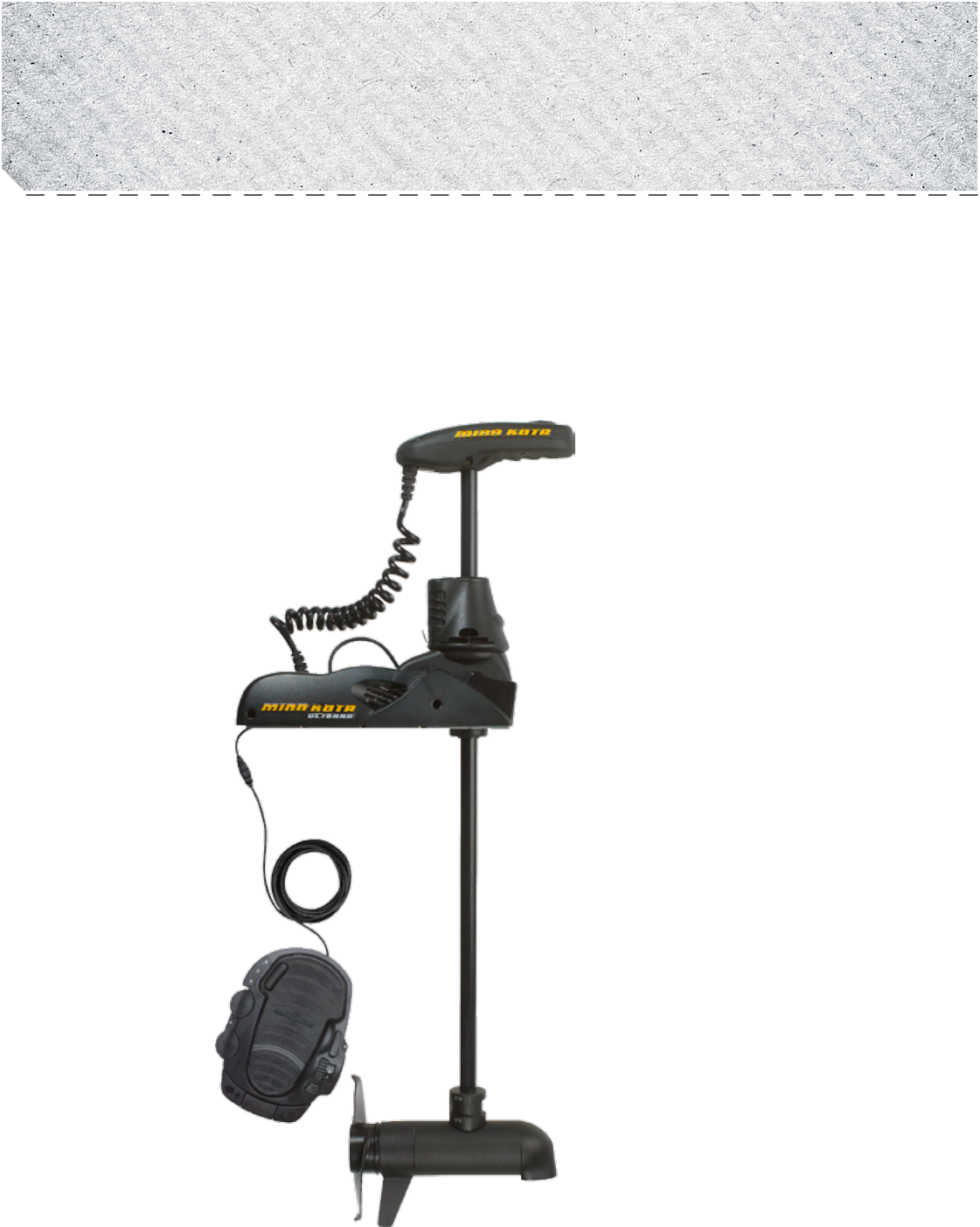
PARTs inCLUdEd
Your new Ulterra comes out of the box with everything you’ll need for direct to boat mounting. This motor can be direct mounted
to the boat or coupled with a Minn Kota quick release bracket for ease of mounting and dismounting. For appropriate quick
release mounting brackets and to locate your nearest dealer, visit minnkotamotors.com. Please review the parts list and tools
needed for installation prior to getting started. To help with future service work or ordering replacement parts please refer to the
information provided in the Parts List section of this manual.

moUnTing oPTions
prop in vs. out (provided in outline?) - content needed
Lorem ipsum dolor sit amet, consectetur adipisicing elit, sed do eiusmod tempor incididunt ut labore et dolore magna aliqua. Ut
enim ad minim veniam, quis nostrud exercitation ullamco laboris nisi ut aliquip ex ea commodo consequat. Duis aute irure dolor in
reprehenderit in voluptate velit esse cillum dolore eu fugiat nulla pariatur. Excepteur sint occaecat cupidatat non proident, sunt in
culpa qui offi cia deserunt mollit anim id est laborum.
TooLs And REsoURCEs REQUiREd:
• Drill
• 5/16” Drill Bit
• 7/16” Box End Wrench
• Wire ties for cable routing
• Phillips Screwdriver
• Flat blade screwdriver
insTALLATion
1. Remove the four sideplate screws. Remove sideplates to access the mounting holes.
2. Remove the two 5/16” E-clips retaining the extension damper. Remove the extension damper to expose the front left mounting
hole.
3. Place the motor on the bow of the boat. It is recommended that the motor be mounted as close to the centerline of the boat
as possible. Ensure that the area under the mounting location is clear of anything that would prevent unobstructed drill and
installation of nuts and washers. Make sure that when deployed, the shaft resides a minimum of 1 ½” from the boat rub rail.
This can be done by measuring from X to X. This should be no less than XX.
Figure 1.
Figure 1. Figure 1.
minnkotamotors.com | 7
©2014 Johnson Outdoors Marine Electronics, Inc.
insTALLATion

4. Once the motor is positioned, mark at minimum four of the six holes that are located farthest apart. Drill through the marked
holes using a 5/16” drill bit
5. Mount the motor to the boat using the provided hardware. Hardware location and orientation should be as shown in the below
fi gure.
6. Reinstall extension damper with shaft facing toward the interior of the boat. Reinstall e-clips
7. Replace the sideplates and sideplate screws.
8. Connect power and other cables
Figure 1.
Figure 1.
Figure 1.
Figure 1.
8 | minnkotamotors.com ©2014 Johnson Outdoors Marine Electronics, Inc.
insTALLATion

boAT Rigging & PRodUCT insTALLATion
For safety and compliance reasons, we recommend that you follow American Boat and Yacht Council (ABYC) standards when
rigging your boat. Altering boat wiring should be completed by a qualifi ed marine technician. The following specifi cations are for
general guidelines only:
CAUTION: These guidelines apply to general rigging to support your Minn Kota motor. Powering multiple motors or additional
electrical devices from the same power circuit may impact the recommended conductor gauge and circuit breaker size. If you are
using wire longer than that provided with your unit, follow the conductor gauge and circuit breaker sizing table below. If your wire
extension length is more than 25 feet, we recommend that you contact a qualifi ed marine technician.
An over-current protection device (circuit breaker or fuse) must be used. Coast Guard requirements dictate that
each ungrounded current-carrying conductor must be protected by a manually reset, trip-free circuit breaker or fuse. The type
(voltage and current rating) of the fuse or circuit breaker must be sized accordingly to the trolling motor used. The table below gives
recommended guidelines for circuit breaker sizing.
Reference:
United States Code of Federal Regulations: 33 CFR 183 – Boats and Associated Equipment
ABYC E-11: AC and DC Electrical Systems on Boats
CondUCToR gAUgE And CiRCUiT bREAKER siZing TAbLE
Motor Thrust /
Model Max Amp Draw Circuit Breaker Wire Extension Length *
5 feet 10 feet 15 feet 20 feet 25 feet
30 lb. 30 50 Amp @ 12 VDC 10 AWG 10 AWG 8 AWG 6 AWG 4 AWG
40 lb., 45 lb. 42 10 AWG 8 AWG 6 AWG 4 AWG 4 AWG
50 lb., 55 lb. 50 60 Amp @ 12 VDC 8 AWG 6 AWG 4 AWG 4 AWG 2 AWG
70 lb. 42 50 Amp @ 24 VDC 10 AWG 10 AWG 8 AWG 8 AWG 6 AWG
80 lb. 56 60 Amp @ 24 VDC 8 AWG 8 AWG 8 AWG 6 AWG 6 AWG
101 lb. 46 50 Amp @ 36 VDC 8 AWG 8 AWG 8 AWG 8 AWG 8 AWG
Engine Mount 101 50 60 Amp @ 36 VDC 8 AWG 6 AWG 4 AWG 4 AWG 2 AWG
112 lb. 52 60 Amp @ 36 VDC 8 AWG 8 AWG 8 AWG 8 AWG 8 AWG
Engine Mount 160 116 (2) x 60 Amp @ 24 VDC 2 AWG 2 AWG 2 AWG 2 AWG 2 AWG
E-Drive 40 50 Amp @ 48 VDC 10 AWG 10 AWG 10 AWG 10 AWG 10 AWG
This conductor and circuit breaker sizing table is only valid for the following assumptions:
1. No more than 3 conductors are bundled together inside of a sheath or conduit outside of engine spaces.
2. Each conductor has 105° C temp rated insulation.
3. No more than 5% voltage drop allowed at full motor power based on published product power requirements.
*Wire Extension Length refers to the distance from the batteries to the trolling motor leads.
sELECTing THE CoRRECT bATTERiEs
The motor will operate with any lead acid, deep cycle marine 12 volt battery/batteries. For best results, use a deep cycle, marine
battery with at least a 105 ampere hour rating. Maintain battery at full charge. Proper care will ensure having battery power
when you need it, and will signifi cantly improve the battery life. Failure to recharge lead-acid batteries (within 12-24 hours) is the
leading cause of premature battery failure. Use a multi-stage charger to avoid overcharging. We off er a wide selection of chargers
to fi t your charging needs. If you are using a crank battery to start a gasoline outboard, we recommend that you use a separate
deep cycle marine battery/batteries for your Minn Kota trolling motor.
Advice Regarding Batteries:
• Never connect the (+) and the (–) terminals of the battery together. Take care that no metal object can fall onto the battery and
short the terminals. This would immediately lead to a short and extreme fi re danger.
• It is highly recommended that a circuit breaker or fuse be used with this trolling motor. Refer to “Conductor Gauge and Circuit
Breaker Sizing Table” in the previous section to fi nd the appropriate circuit breaker or fuse for your motor. For motors requiring
a 60-amp breaker, the Minn Kota MKR-19 60-amp circuit breaker is recommended.
minnkotamotors.com | 9
©2014 Johnson Outdoors Marine Electronics, Inc.
bATTERY wiRing & insTALLATion
sELECTing THE CoRRECT bATTERiEs
The motor will operate with any lead acid, deep cycle marine 12 volt battery/batteries. For best results, use a deep cycle, marine
battery with at least a 105 ampere hour rating. Maintain battery at full charge. Proper care will ensure having battery power
when you need it, and will signifi cantly improve the battery life. Failure to recharge lead-acid batteries (within 12-24 hours) is the
leading cause of premature battery failure. Use a multi-stage charger to avoid overcharging. We off er a wide selection of chargers
to fi t your charging needs. If you are using a crank battery to start a gasoline outboard, we recommend that you use a separate
deep cycle marine battery/batteries for your Minn Kota trolling motor.
Advice Regarding Batteries:
•
Never connect the (+) and the (–) terminals of the battery together. Take care that no metal object can fall onto the battery and
short the terminals. This would immediately lead to a short and extreme fi re danger.
•
It is highly recommended that a circuit breaker or fuse be used with this trolling motor. Refer to “Conductor Gauge and Circuit
Breaker Sizing Table” in the previous section to fi nd the appropriate circuit breaker or fuse for your motor. For motors requiring
a 60-amp breaker, the Minn Kota MKR-19 60-amp circuit breaker is recommended.
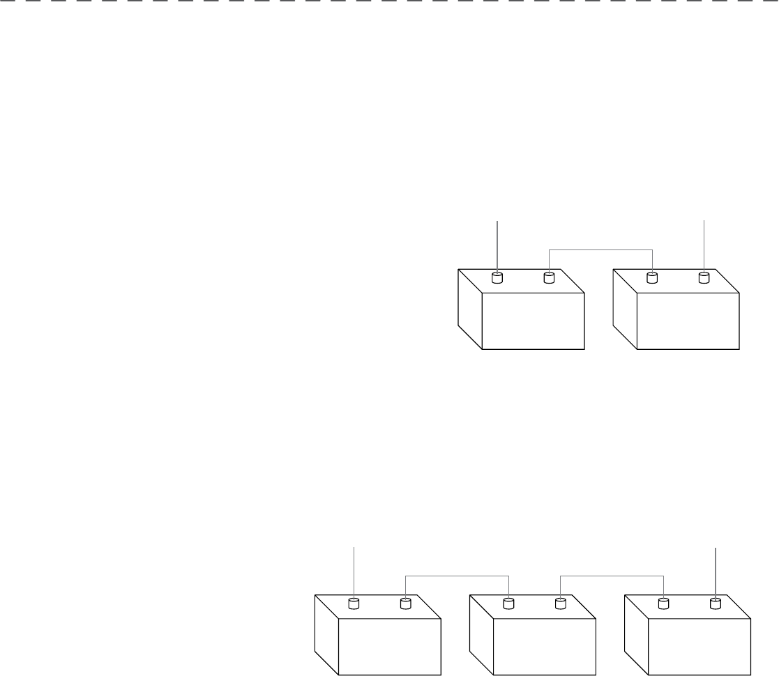
ConnECTing THE bATTERiEs in sERiEs
(if REQUiREd foR YoUR moToR)
24 voLT sYsTEms:
1. Make sure that the motor is switched off (speed selector on “0”).
2. Two 12 volt batteries are required.
3. The batteries must be wired in series, only as directed in wiring
diagram, to provide 24 volts.
a. Connect a connector cable to the positive ( + ) terminal of
battery 1 and to the negative ( – ) terminal of battery 2.
b. Connect positive ( + ) red lead to positive ( + ) terminal on battery 2.
c. Connect negative ( – ) black lead to negative ( – ) terminal of battery 1.
4. For safety reasons do not switch the motor on until the propeller is in the water. If installing a leadwire plug, observe proper
polarity and follow instructions in your boat owner’s manual. See wiring diagram on following pages.
CAUTION
• For safety reasons, disconnect the motor from the battery or batteries when the motor is not in use or while
the battery/batteries are being charged.
• Improper wiring of 24/36 volt systems could cause battery explosion!
• Keep leadwire wing nut connection tight and solid to battery terminals.
• Locate battery in a ventilated compartment.
To trolling motor negative
24 Volt Connection
Battery #1 (Low Side)
Neg - Neg -Pos + Pos +
Battery #2 (High Side)
+24 Volts to trolling motor
positive (or circuit breaker)
24 Volt Series Connection
How To ConnECT THE bATTERiEs in sERiEs (if REQUiREd foR YoUR moToR)
36 voLT sYsTEms:
1. Make sure that the motor is switched off
(speed selector on “0”).
2. Three 12 volt batteries are required.
3. The batteries must be wired in series, only as
directed in wiring diagram, to provide 36 volts.
a. Connect a connector cable to the
positive ( + ) terminal of battery 1
and to the negative ( – ) terminal
of battery 2 and another connector
cable from the positive ( + ) terminal of battery 2 to the negative ( – ) terminal of battery of battery 3.
b. Connect positive ( + ) red lead to positive ( + ) terminal on battery 3.
c. Connect negative ( – ) black lead to negative ( – ) terminal of battery 1.
4. For safety reasons do not switch the motor on until the propeller is in the water. If installing a leadwire plug, observe proper
polarity and follow instructions in your boat owner’s manual. See wiring diagram on following pages.
CAUTION
• Improper wiring of 24/36 volt systems could cause battery explosion!
• Keep leadwire wing nut connection tight and solid to battery terminals.
• Locate battery in a ventilated compartment.
• For safety reasons, disconnect the motor from the battery or batteries when the motor is not in use or while
the battery/batteries are being charged.
To trolling motor negative
24 Volt Connection 36 Volt Connection
Battery #1 (Low Side)
Neg - Neg - Neg -Pos + Pos + Pos +
Battery #2 Battery #3 (High Side)
+36 Volts to trolling motor
positive (or circuit breaker)
36 Volt Series Connection
10 | minnkotamotors.com ©2014 Johnson Outdoors Marine Electronics, Inc.
bATTERY wiRing & insTALLATion
ConnECTing THE bATTERiEs in sERiEs
(if REQUiREd foR YoUR moToR)
24 voLT sYsTEms:
1. Make sure that the motor is switched off (speed selector on “0”).
2. Two 12 volt batteries are required.
3. The batteries must be wired in series, only as directed in wiring
diagram, to provide 24 volts.
a. Connect a connector cable to the positive ( + ) terminal of
battery 1 and to the negative ( – ) terminal of battery 2.
b. Connect positive ( + ) red lead to positive ( + ) terminal on battery 2.
c. Connect negative ( – ) black lead to negative ( – ) terminal of battery 1.
4. For safety reasons do not switch the motor on until the propeller is in the water. If installing a leadwire plug, observe proper
polarity and follow instructions in your boat owner’s manual. See wiring diagram on following pages.
CAUTION
• For safety reasons, disconnect the motor from the battery or batteries when the motor is not in use or while
the battery/batteries are being charged.
• Improper wiring of 24/36 volt systems could cause battery explosion!
• Keep leadwire wing nut connection tight and solid to battery terminals.
• Locate battery in a ventilated compartment.
To trolling motor negative
24 Volt Connection
Battery #1 (Low Side)
Neg - Neg -Pos + Pos +
Battery #2 (High Side)
+24 Volts to trolling motor
positive (or circuit breaker)
24 Volt Series Connection
How To ConnECT THE bATTERiEs in sERiEs (if REQUiREd foR YoUR moToR)
36 voLT sYsTEms:
1. Make sure that the motor is switched off
(speed selector on “0”).
2. Three 12 volt batteries are required.
3. The batteries must be wired in series, only as
directed in wiring diagram, to provide 36 volts.
a. Connect a connector cable to the
positive ( + ) terminal of battery 1
and to the negative ( – ) terminal
of battery 2 and another connector
cable from the positive ( + ) terminal of battery 2 to the negative ( – ) terminal of battery of battery 3.
b. Connect positive ( + ) red lead to positive ( + ) terminal on battery 3.
c. Connect negative ( – ) black lead to negative ( – ) terminal of battery 1.
4. For safety reasons do not switch the motor on until the propeller is in the water. If installing a leadwire plug, observe proper
polarity and follow instructions in your boat owner’s manual. See wiring diagram on following pages.
CAUTION
• Improper wiring of 24/36 volt systems could cause battery explosion!
• Keep leadwire wing nut connection tight and solid to battery terminals.
• Locate battery in a ventilated compartment.
• For safety reasons, disconnect the motor from the battery or batteries when the motor is not in use or while
the battery/batteries are being charged.
To trolling motor negative
24 Volt Connection 36 Volt Connection
Battery #1 (Low Side)
Neg - Neg - Neg -Pos + Pos + Pos +
Battery #2 Battery #3 (High Side)
+36 Volts to trolling motor
positive (or circuit breaker)
36 Volt Series Connection
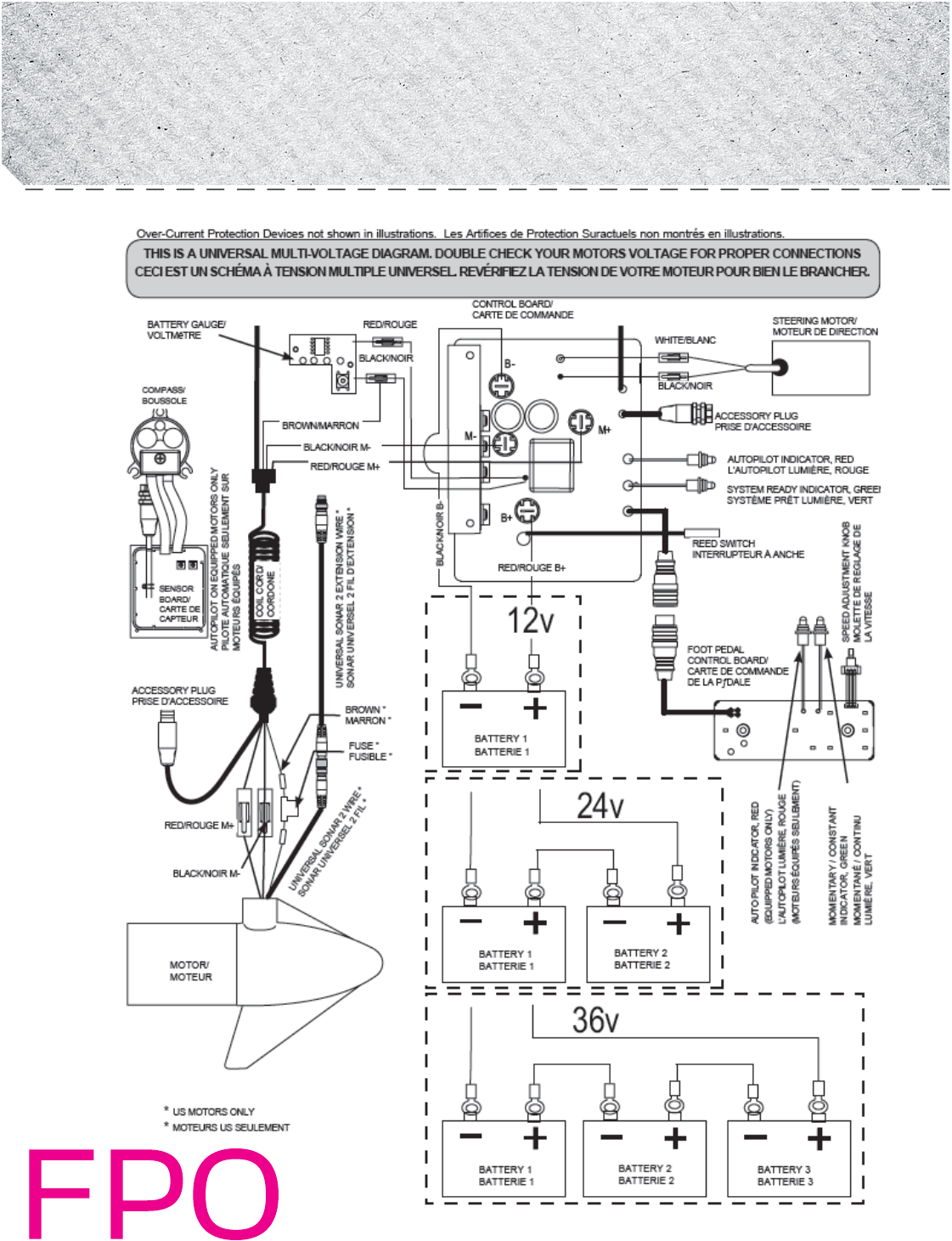
NOTE: This is a universal, multi-voltage diagram. Double-check your motor's voltage for proper connections. Over-Current
Protection Devices not shown in this illustration.
minnkotamotors.com | 11
©2014 Johnson Outdoors Marine Electronics, Inc.
moToR wiRing diAgRAm
12 | minnkotamotors.com ©2014 Johnson Outdoors Marine Electronics, Inc.
gETTing sTARTEd
Specifications subject to change without notice.
*This diagram is for reference only and may differ from your actual motor.
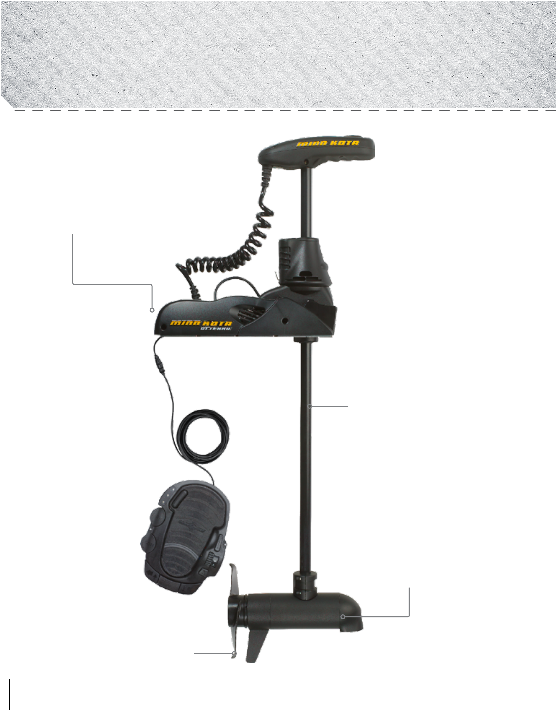
Weedless Wedge 2 Propeller
Cool Quiet
Power Motor
Mounting Bracket
Lifetime Warranty
Flexible Composite Shaft
moToR fEATUREs
minnkotamotors.com | 13
©2014 Johnson Outdoors Marine Electronics, Inc.
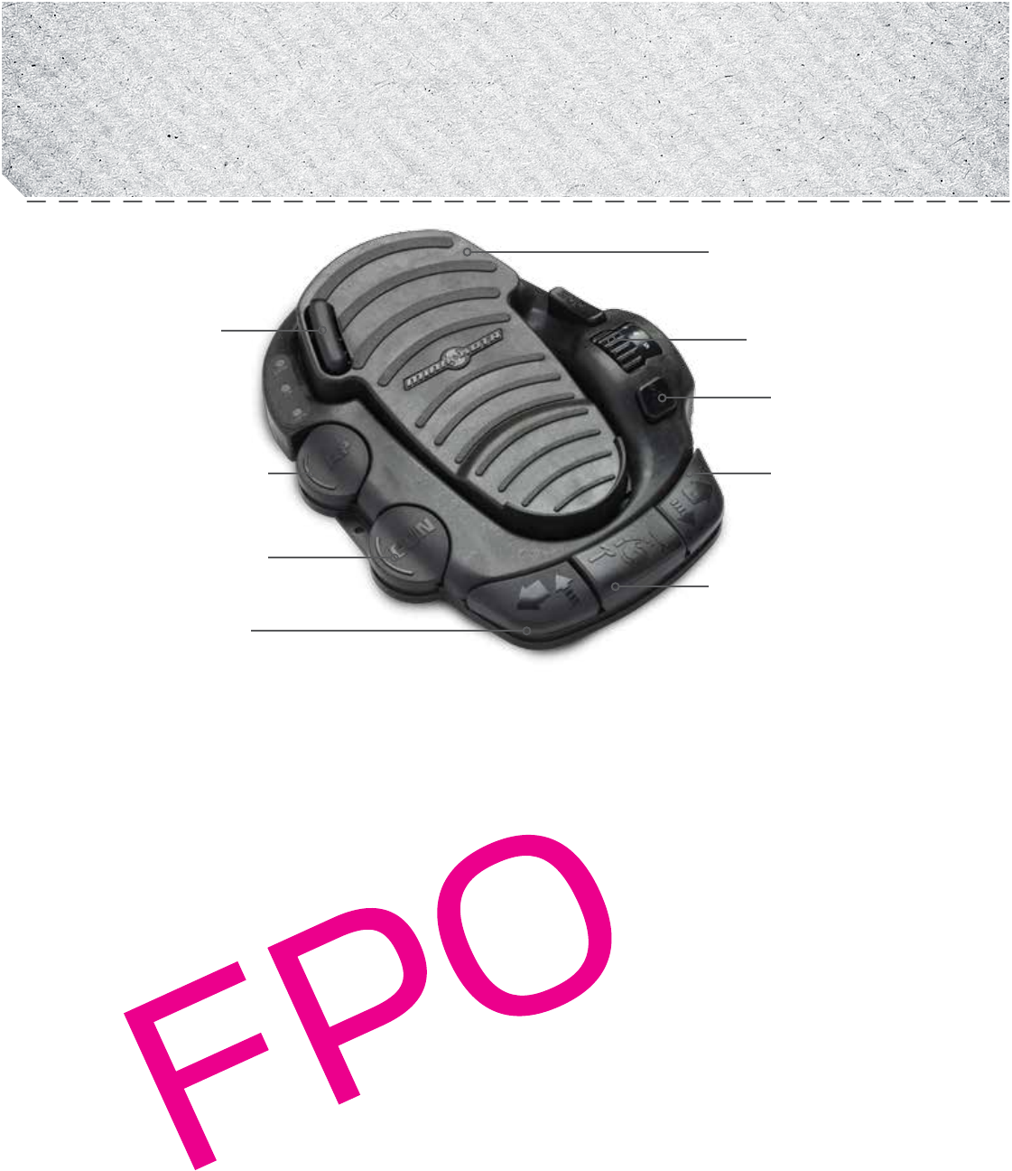
gETTing sTARTEd
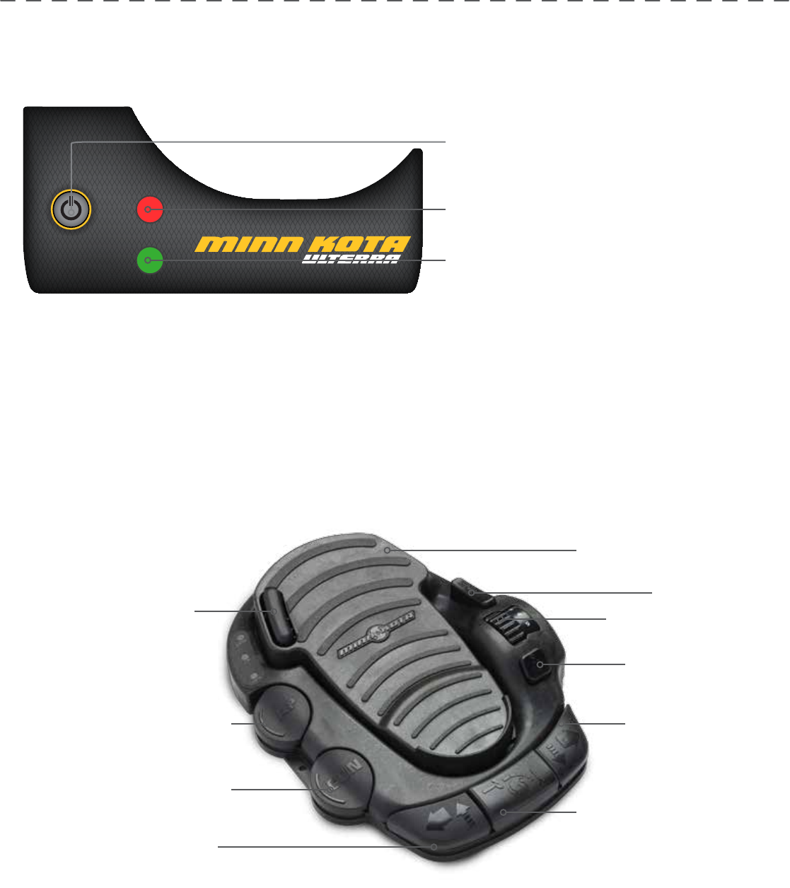
SYSTEM READY
POWER
STATUS
Momentary/Constant
"ON"/"OFF"
AutoPilot "ON"/"OFF"
Momentary On
Power Switch: depressing of power switch is
required to power’ the motor on/off
Status (red LED):
System Ready (green LED): The motor is
equipped with a system ready indicator. The
indicator light will be illuminated when the motor is
connected to power and switched on.
Heel/Toe Steering
Mode
Speed Control
Spot-Lock
Right Steer /
Trim Down
Stow/Deploy/Prop
Left Steer / Trim Up
ConTRoL PAnEL
fooT PEdAL fEATUREs
14 | minnkotamotors.com ©2014 Johnson Outdoors Marine Electronics, Inc.
gETTing sTARTEd
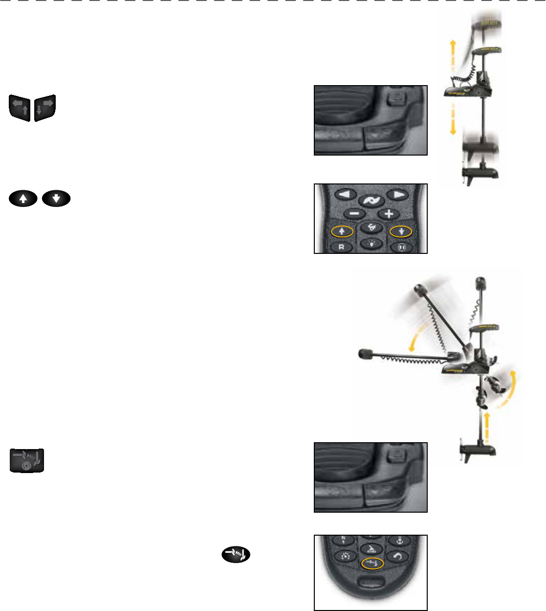
TRimming UP And down
Lorem ipsum dolor sit amet, consectetur adipisicing elit, sed do eiusmod tempor incididunt ut labore et
dolore magna aliqua. Ut enim ad minim veniam, quis nostrud exercitation ullamco laboris nisi ut aliquip
ex ea commodo consequat. Duis aute irure dolor in reprehenderit in voluptate velit esse cillum dolore eu
Trimming Up and Down using the Foot Pedal: Lorem ipsum
dolor sit amet, consectetur adipisicing elit, sed do eiusmod
tempor incididunt ut labore et dolore magna aliqua. Ut enim
ad minim veniam, quis nostrud exercitation ullamco laboris nisi ut aliquip
ex ea commodo consequat. Duis aute irure dolor in reprehenderit in
voluptate velit
Trimming Up and Down using the i-Pilot remote: Lorem ipsum
dolor sit amet, consectetur adipisicing elit, sed do
eiusmod tempor incididunt ut labore et dolore magna aliqua. Ut enim ad
minim veniam, quis nostrud exercitation ullamco laboris nisi ut aliquip
ex ea commodo consequat. Duis aute irure dolor in reprehenderit in
voluptate velit
sTowing And dEPLoYing THE moToR
Lorem ipsum dolor sit amet, consectetur adipisicing elit, sed do eiusmod tempor
incididunt ut labore et dolore magna aliqua. Ut enim ad minim veniam, quis nos-
trud exercitation ullamco laboris nisi ut aliquip ex ea commodo consequat. Duis
aute irure dolor in reprehenderit in voluptate velit esse cillum dolore eu fugiat nulla
pariatur. Excepteur sint occaecat cupidatat non proident, sunt in culpa qui officia
deserunt mollit anim id est laborum
Stowing and Deploying the Motor with the Foot Pedal:
Lorem ipsum dolor sit amet, consectetur adipisicing elit, sed
do eiusmod tempor incididunt ut labore et dolore magna
aliqua. Ut enim ad minim veniam, quis nostrud exercitation ullamco
laboris nisi ut aliquip ex ea commodo consequat. Duis aute irure dolor in
reprehenderit in voluptate
Stowing and Deploying the Motor with the i-Pilot remote:
Lorem ipsum dolor sit amet, consectetur adipisicing elit, sed
do eiusmod tempor incididunt ut labore et dolore magna aliqua. Ut enim
ad minim veniam, quis nostrud exercitation ullamco laboris nisi ut aliquip
ex ea commodo consequat. Duis aute irure dolor in reprehenderit in
voluptate

minnkotamotors.com | 15
©2014 Johnson Outdoors Marine Electronics, Inc.
gETTing sTARTEd
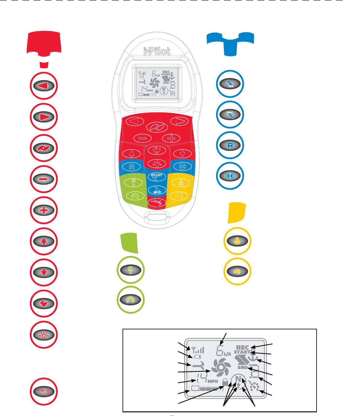
Knowing YoUR REmoTE
LAYoUT
The i-Pilot remote is divided into four sections: Manual Control, Tracks, Spot Lock, and Cruise Control/AutoPilot. Buttons in
the Manual Control section of the remote do not require a GPS signal to operate and give you full, immediate control over steering,
speed and prop functions similar to a CoPilot. All other buttons require a minimum GPS signal strength of one bar in order to operate.
Buttons located in the Tracks section are used for track recording and playback. Spot Lock buttons are located in the Spot Lock
section. Cruise Control/AutoPilot are located in the Cruise Control/AutoPilot section.
ConsTRUCTion
The remote is waterproof and fl oats in water.
RAngE
The range of the remote will be greatly reduced if it is used near or mounted to any metal object including aluminum or steel. It is also
recommended that the front end of the remote not be obstructed during use.
bATTERY LifE
Remote battery life is subject to frequency of use and is especially impacted by how often the LCD backlight is used.
When the remote battery is low, will appear on the remote LCD. The Backlight button will be disabled when is displayed to
conserve battery power.
PowER
When a button is pressed on the remote it will automatically turn on. To turn the remote off press and hold for three seconds. The
remote will automatically turn itself off thirty minutes after the last button press if a learned i-Pilot controller is powered up and within
transmitting range. The remote will turn off after three seconds if the i-Pilot controller is powered down or out of transmitting range.
KEYPAd LoCK
The user can lock the keypad during use to help avoid accidental key activations. To lock or unlock the keypad, press and hold for
3 seconds. When the keypad is locked, will appear on the remote LCD. Note that the keypad is always unlocked when the remote is
fi rst turned on.
minnkotamotors.com | 17
©2014 Johnson Outdoors Marine Electronics, Inc.
sECTion TiTLEgETTing sTARTEd
16 | minnkotamotors.com ©2014 Johnson Outdoors Marine Electronics, Inc.
gETTing sTARTEd
P/N: 2207102
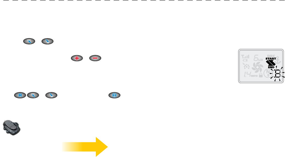
REmoTE ConTRoL QUiCK REfEREnCE gUidE
mAnUAL
ConTRoL
Steer Left
Steer Right
Prop On/Off
Speed Down
Speed Up
Stow Motor
Deploy Motor
High Speed Bypass
Toggles the motor speed
between its current setting
and speed 10.
Backlight
Turns the remote LCD
backlighting on for six
seconds.
Keypad Lock/Unlock
To lock or unlock the keypad,
press and hold the backlight
button for 3 seconds.
Trim Motor
Advanced AutoPilot and
AutoPilot
Turns Advanced AutoPilot on
and off when pressed once. Turns
AutoPilot on when held for two
seconds.
Cruise Control
Turns cruise control on and off using the
current GPS speed as the target speed.
Spot-Lock
Turns Spot-Lock on and
records it to a memory location.
Spot-Lock Recall
Recalls a Spot-Lock from
memory and turns spot lock on.
Track to End
Navigates to the nearest location
on a previously recorded track
and follows it to its end.
Track to Start
Navigates to the nearest location
on a previously recorded track
and follows it to its start.
Track Record
Starts and ends the recording
of a track to a selected memory
location.
Record Pause/Escape
Pauses the recording of a track
and then resumes the recording
when pressed again.
TRACKs
sPoT-LoCK
CRUisE ConTRoL/
AUToPiLoT
GPS Signal strength
Remote Battery Low
Stow/Deploy
Prop On/Off
GPS Speed
Motor Battery Status
Keypad Lock
Track Record On
Track to Start On
Spot Lock On
Track to End On
Memory Location
Cruise Control On
AutoPilot On
Advanced
AutoPilot On
Motor Speed
minnkotamotors.com | 17
©2014 Johnson Outdoors Marine Electronics, Inc.
gETTing sTARTEd
Knowing YoUR i-PiLoT ConTRoLLER
ConsTRUCTion
The i-Pilot controller contains a very sensitive digital compass and is where all GPS satellite and
i-Pilot remote signals are received. It is very important that the controller have a clear view of
the sky in all directions and has a clear line of sight to the remote for optimum performance. All
electronics within the controller enclosure are completely sealed.
REmoTE LEARning
The i-Pilot remote is prelearned to the controller from the factory. The top of the controller
has a single learn button to allow additional remotes to be added to the system. To learn
additional remotes:
1. Power up the trolling motor.
2. Push and hold the learn button down. A steady audio tone will be heard while holding this button.
3. While holding the learn button down push any button on the remote being programmed. Three beeps will be heard when the remote
is successfully learned.
A remote can only be learned to one controller at a time. A controller can have an unlimited number of remotes learned to it. During
the learn process, the remote must start out in the OFF condition. If necessary, the remote can be turned off by pressing and
holding the Pause button for three seconds.
minnkotamotors.com | 19
©2014 Johnson Outdoors Marine Electronics, Inc.
gETTing sTARTEd
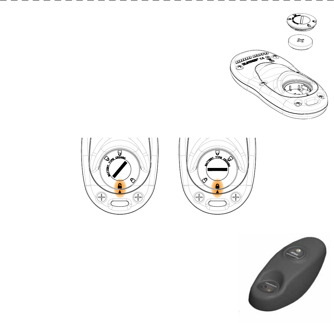
REmoTE bATTERY REPLACEmEnT
1. Make sure hands are clean, dry and static free. Discharge any static
electricity by touching a metal object that is grounded. *Static electricity can
damage the circuit board.
2. With the remote upside down, use a large coin to rotate the battery door
counterclockwise until either of the Unlock icons align with the arrow
(see Figure B).
3. Remove battery cover and old battery and replace with new CR2450 coin cell
battery. Note the proper polarity of the battery (see Figure A).
4. Ensure the two rubber o-rings are properly seated in the underside of the battery
cover.
5. Replace battery cover by aligning either of the Unlock icons with the
arrow, pressing the cover down and rotating clockwise until the Lock icon aligns with
the arrow (see Figure C).
FIGURE A
FIGURE B FIGURE C
18 | minnkotamotors.com ©2014 Johnson Outdoors Marine Electronics, Inc.
gETTing sTARTEd
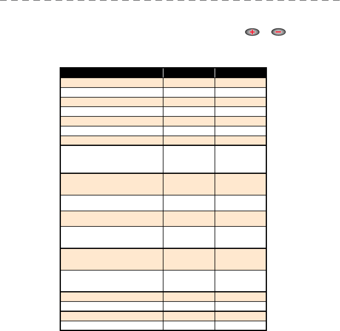
AUdio modEs
The i-Pilot Controller also contains an internal speaker which can be programmed to work in two diff erent audio modes. The speaker is
programmed to operate in audio mode one from the factory. To enable diff erent audio modes hold and down at the same
time for three seconds. For an explanation of each audio mode and their sounds see the table below.
wHAT CondiTion CAUsEs iT AUdio modE AUdio PATTERn
Startup Modes 1 and 2 4 Short beeps
Manual prop on Mode 2 Single beep
Manual prop off Mode 2 Double beep
Speed + (when less than max speed) Mode 2 Single beep
Speed - (when greater than speed 0) Mode 2 Single beep
High Speed Bypass enable Mode 2 Single beep
High Speed Bypass disable Mode 2 Double beep
Button press for any of these (enable or
disable): REC, Pause, Track to Start, Track
to End, AutoPilot, Cruise Control, Spot
Lock, Spot Lock Recall
Mode 2 Single beep
Moving more than a quarter mile from
the last track point while in Record Pause
mode
Mode 2 Error
When GPS Signal Strength goes to no
bars while in a GPS-based mode Mode 2 Error
Attempting to enable a GPS feature when
no signal strength bars are shown Mode 2 Error
Attempting to replay a Track or recall
a Spot Lock location when the boat is
beyond the minimum distance
Mode 2 Error
MOM button on the footpedal is pressed
and a remote button press attempts to
override it
Mode 2 Error
End of track attained during track playback
(in conjunction with cancelling mode and
turning the prop off )
Mode 2
High-Low,
High-Low,
High-Low
Switch to Audio Mode 1 Modes 1 and 2 Single beep
Switch to Audio Mode 2 Modes 1 and 2 Double beep
Learn button is pressed Modes 1 and 2 Steady tone
Learn successfully completed Modes 1 and 2 3 longer beeps
20 | minnkotamotors.com ©2014 Johnson Outdoors Marine Electronics, Inc.
gETTing sTARTEd
minnkotamotors.com | 19
©2014 Johnson Outdoors Marine Electronics, Inc.
gETTing sTARTEd
PowER
The i-Pilot controller will turn on whenever the trolling motor has power. For Terrova and Riptide ST motors this is when the green
system ready light is on. For PowerDrive V2 and Riptide SP motors this is whenever the motor is connected to power.
*For this reason it is very important to disconnect a PowerDrive V2 or Riptide SP motor from power when not in use or battery
drain will occur.
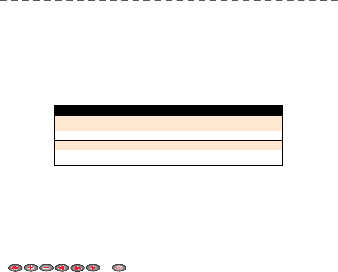
ACCURACY
The accuracy and responsiveness with which i-Pilot controls your boat is highly dependent upon many variables. Just a few of
these variables and their general eff ects on responsiveness and accuracy are given below so that the behavior of the system can be
understood.
sYsTEm sTARTUP
Once you have verifi ed i-Pilot’s installation it’s time to start using it on the water. Follow these simple steps each time you power up
your trolling motor for successful operation:
1. Connect trolling motor to power.
2. Deploy trolling motor into water.
3. Push any button on your remote. The remote LCD will show prop speed and GPS signal strength.
4. You are now able to use all manual functions:
and .
5. After i-Pilot has obtained a minimum GPS signal strength of one bar, all remaining functions will become available.
vARiAbLE EffECT
Ratio of motor thrust to
boat weight
Excessive thrust on a smaller boat can cause i-Pilot to overcorrect.
Not enough thrust on a large boat can cause i-Pilot to respond slowly.
Wind Excessive wind and/or current can reduce i-Pilot’s positioning accuracy.
GPS signal strength The greater number of GPS signal bars the greater the accuracy.
Trolling motor
battery power level A fully charged battery will give the best performance.
minnkotamotors.com | 21
©2014 Johnson Outdoors Marine Electronics, Inc.
gETTing sTARTEd
20 | minnkotamotors.com ©2014 Johnson Outdoors Marine Electronics, Inc.
gETTing sTARTEd
mAnUAL ConTRoL fUnCTionALiTY
This section describes all Manual Control functions of i-Pilot. A manual function is one in which the operator takes full control of the
function such as manually steering the motor in a desired direction or manually adjusting the prop speed to the desired setting. Any of
these functions do not require a GPS signal.
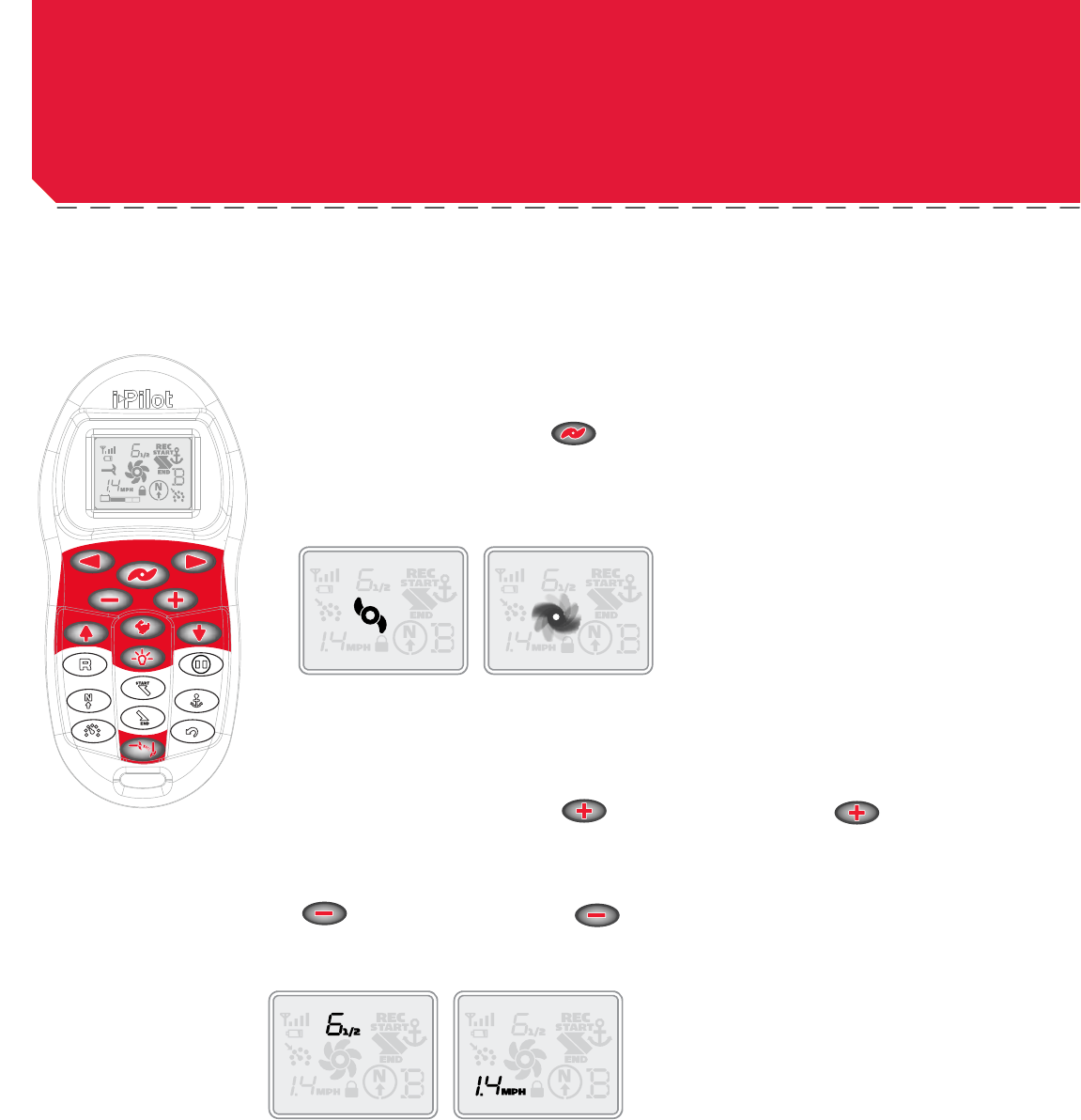
moToR on/off
To turn the motor on or off press .
The prop icon on the LCD will be on if the prop is enabled and off if the prop is disabled. With the
prop enabled, the icon will be stationary if the motor speed is zero and the icon will rotate if the motor
speed is greater than zero.
moToR sPEEd ConTRoL
Increase Motor Speed
To increase the motor speed push on the remote. Each push of will increment the motor
speed by ½ to a maximum of 10.
dECREAsE moToR sPEEd
To decrease the motor speed push on the remote. Each push of will decrement the motor speed by ½ to a minimum of 0.
The remote LCD will display the current motor speed setting. This is not to be confused with the GPS speed which is also displayed on
the remote LCD.
Prop Enabled Motor Speed Greater
Than Zero
Motor Speed GPS Speed
22 | minnkotamotors.com ©2014 Johnson Outdoors Marine Electronics, Inc.
sECTion TiTLEmAnUAL ConTRoL

minnkotamotors.com | 21
©2014 Johnson Outdoors Marine Electronics, Inc.
moToR sTEERing ConTRoL
Steer Left
To steer the motor to the left press .
Steer right
To steer the motor to the right press .
If a steering button is held down for more than six to eight seconds, the steering will stop to prevent the coil cord from wrapping on
the motor.
HigH sPEEd bYPAss oPERATion
Engage
Pressing will set the motor speed to maximum immediately.
Disengage
Pressing again will set the motor speed to the value it was at previously.
*Note: High Speed Bypass does not enable or disable the prop.
LCd bACKLigHT bUTTon
To turn on LCD backlighting press and release .
The backlight will turn off eight seconds after the last button press to conserve battery power.
fooT PEdAL oPERATion
• Pressing the MOM or CON button on the foot pedal will adjust the motor speed setting to the foot pedal speed setting.
• While the MOM button is pressed on the foot pedal, all speed and prop changes from the i-Pilot are ignored.
minnkotamotors.com | 23
©2014 Johnson Outdoors Marine Electronics, Inc.
mAnUAL ConTRoL

UndERsTAnding How THE i-PiLoT sYsTEm woRKs
nAvigATion
i-Pilot uses GPS satellite signals as well as digital compass data to know where it is, where it is heading and the direction the motor
is pointing. Since i-Pilot depends on GPS satellite signals for navigation, a minimum GPS signal level of one bar is required in order
for GPS navigation controls to be enabled. Best results are achieved when a GPS signal level of four bars can be obtained.
In simple terms, i-Pilot remembers and creates points to navigate your boat automatically. i-Pilot also uses a method of GPS
navigation called arrival circles. These imaginary circles allow i-Pilot to understand when it has drifted away from a point and when
it has arrived at a point. The size of the arrival circles vary depending on GPS signal strength, thus the greater the signal strength
the smaller the arrival circles.
TRACKs
Tracks are made of many points that i-Pilot records when recording a track. The distance between these points varies based on GPS
signal strength and the speed at which you record the track. When a track is played back, i-Pilot uses the track points and arrival
circles to navigate the track.
mEmoRY
i-Pilot has the capability of storing up to six individual tracks (each two miles in length) and six individual
Spot Lock locations. These locations are stored in memory even when power is removed from the system.
Spot Lock and Track memory locations are separate from each other and they cannot over write each
other. Memory locations are identifi ed on the remote LCD with an icon shown as A, B, C, D, E or F. When
the memory icon is fl ashing, a diff erent location can be selected by pressing or .
24 | minnkotamotors.com ©2014 Johnson Outdoors Marine Electronics, Inc.
sECTion TiTLEgPs moToR ConTRoL
22 | minnkotamotors.com ©2014 Johnson Outdoors Marine Electronics, Inc.
minnkotamotors.com | 25
©2014 Johnson Outdoors Marine Electronics, Inc.
sECTion TiTLE
How sPoT LoCK woRKs
sPoT LoCK
Spot Lock uses a single point as a reference for the spot you want to stay on. This point is
recorded and stored into one of the six memory locations when the Spot Lock button is pushed.
Around the Spot Lock location i-Pilot uses an arrival circle to determine prop speed and
direction. If i-Pilot sees it is within the circle, it will adjust the motor speed to zero. If i-Pilot sees it
is outside of the circle, it will control motor speed in an attempt to get the boat back into the circle.
sPoT LoCK
minnkotamotors.com | 23
©2014 Johnson Outdoors Marine Electronics, Inc.
26 | minnkotamotors.com ©2014 Johnson Outdoors Marine Electronics, Inc.
sPoT LoCK
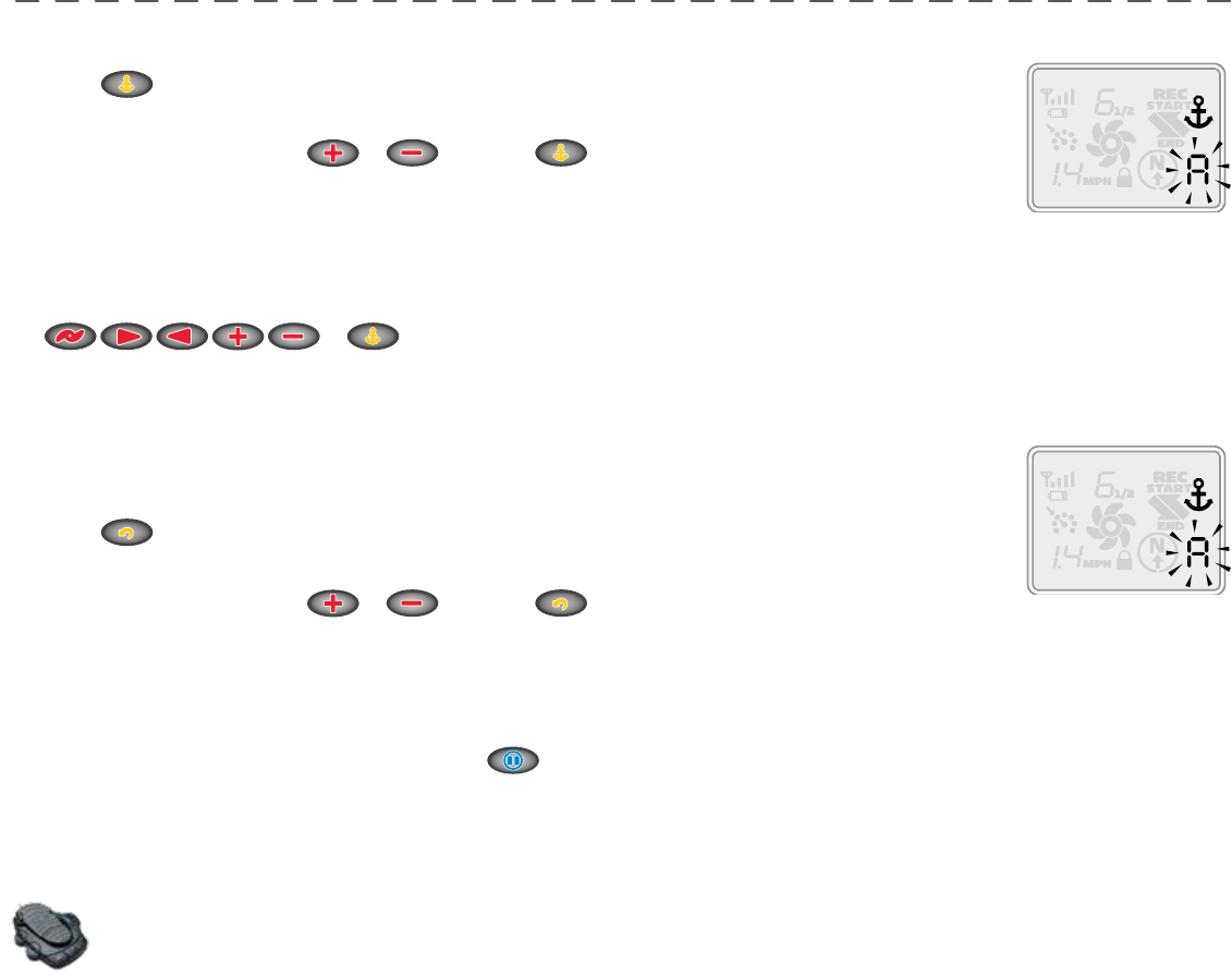
EngAging sPoT LoCK
1. Press on the remote.
2. The Memory Location icon will fl ash on the remote LCD for three seconds, allowing you to choose a
memory location by pressing or . Pressing again or waiting for three seconds accepts the
memory location.
disEngAging sPoT LoCK
1. To disengage Spot Lock press any of these buttons:
or .
RE-EngAgE A sAvEd sPoT LoCK LoCATion
1. Manually navigate the boat to within a quarter mile of the saved Spot Lock location. Due to safety
reasons, i-Pilot will not re-engage a saved Spot Lock location greater than a quarter mile away.
2. Press on the remote.
3. The Memory Location icon will fl ash on the remote LCD for three seconds allowing you to choose a
memory location by pressing or . Pressing again or waiting for three seconds accepts the
memory location.
sPoT LoCK EsCAPE
1. If the Spot Lock button is accidentally hit, press or any manual navigation button within three seconds to cancel the
command.
fooT PEdAL oPERATion
• Pressing any foot pedal button will disengage Spot Lock.
• The momentary button on the foot pedal will not function when Spot Lock or Spot Lock Recall is engaged.
Using sPoT LoCK wiTH oTHER i-PiLoT fUnCTions
Since Spot Lock takes over full control of the motor, it cannot be used in combination with other i-Pilot functions.
24 | minnkotamotors.com ©2014 Johnson Outdoors Marine Electronics, Inc.
minnkotamotors.com | 27
©2014 Johnson Outdoors Marine Electronics, Inc.
sECTion TiTLE
How CRUisE ConTRoL woRKs
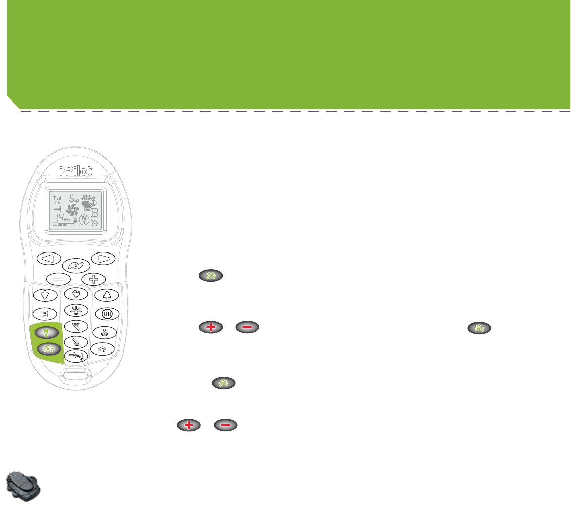
CRUisE ConTRoL
i-Pilot automatically controls the motor speed to maintain a constant GPS speed.
EngAging CRUisE ConTRoL
1. Press on the remote.
2. The current GPS speed will fl ash, displaying your current speed as the target GPS speed on the
remote LCD for three seconds.
3. Press or to increase or decrease the target speed or press again to engage
Cruise Control immediately.
disEngAgE CRUisE ConTRoL
1. Pressing will disengage Cruise Control.
AdjUsTing TARgET sPEEd wiTH CRUisE ConTRoL EngAgEd
1. With Cruise Control engaged press or to adjust the target speed by 0.1 MPH increments.
fooT PEdAL oPERATion
• Adjusting the motor speed or pressing the CON button from the foot pedal will disengage Cruise Control.
Using CRUisE ConTRoL wiTH oTHER i-PiLoT fUnCTions
Cruise Control can be used in combination with Advanced AutoPilot, AutoPilot, Track Recording, and Track Playback.
CRUisE ConTRoL
minnkotamotors.com | 25
©2014 Johnson Outdoors Marine Electronics, Inc.
28 | minnkotamotors.com ©2014 Johnson Outdoors Marine Electronics, Inc.
sECTion TiTLEAUToPiLoT
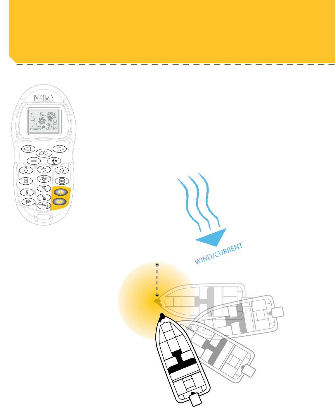
How AUToPiLoT woRKs
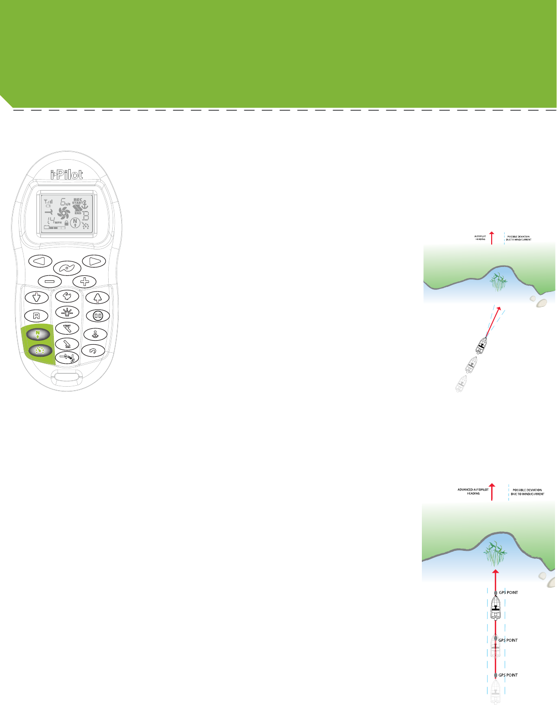
Two diff erent versions of AutoPilot are available: Advanced AutoPilot and AutoPilot. There
are distinct diff erences between the two AutoPilots and how they control your boat.
AUToPiLoT
AutoPilot uses an internal compass to provide heading lock.
When AutoPilot is on, it keeps the motor pointed in the same
compass direction. If a manual steering correction is made,
AutoPilot locks onto the new compass heading to which the
boat was steered. This method of heading tracking does not take
into account external forces such as a side wind or currents, which
can allow side drift.
AdvAnCEd AUToPiLoT
Advanced AutoPilot not only uses compass heading but
also GPS signal data to correct for cross winds, current and
other external forces to keep the boat on a straight line. When
Advanced AutoPilot is turned on, it generates a set of GPS
points in a straight track line in the heading direction. i-Pilot
now navigates to each individual point on this track line. When
the user steers to a new heading, a new track line of GPS points
are laid down in the new heading direction.
26 | minnkotamotors.com ©2014 Johnson Outdoors Marine Electronics, Inc.
minnkotamotors.com | 29
©2014 Johnson Outdoors Marine Electronics, Inc.
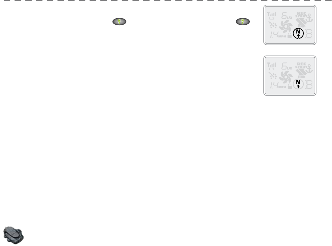
AUToPiLoT
EngAging AdvAnCEd AUToPiLoT And AUToPiLoT
1. To engage Advanced AutoPilot, press once. To engage AutoPilot, press and hold
for two seconds.
2. The Advanced AutoPilot or AutoPilot icon will be displayed on the remote LCD.
3. To adjust desired heading, manually steer motor to new heading. i-Pilot will lock onto new heading.
wHiCH AUToPiLoT do i UsE And wHEn?
With all the external variables, this question can be diffi cult to answer. Both AutoPilots have their benefi ts based on the type of fi shing
and bait presentation desired.
Advanced AutoPilot will keep the boat on a true straight path in most conditions. When very extreme conditions exists such as very
strong winds or current, the trolling motor may not have enough power to control the boat smoothly. In these extreme cases it may be
best to use AutoPilot and let the boat move with the wind or current if the motor is not powerful enough to overcome it.
AutoPilot helps you maintain a constant heading but does not compensate for wind or currents.
Both Advanced AutoPilot and AutoPilot are valuable tools the fi sherman can use for accurate and precise bait presentation.
We highly recommend getting on the water and trying both Advanced AutoPilot and AutoPilot in various fi shing situations and
applications. With experimentation and time you will fi nd which AutoPilot works best for you in a given situation.
fooT PEdAL oPERATion
• Advanced AutoPilot can be turned on by pressing the AP button on the foot pedal.
• AutoPilot
cannot
be turned on by using the AP button on the pedal.
Using AdvAnCEd AUToPiLoT And AUToPiLoT wiTH oTHER i-PiLoT fUnCTions
Advanced AutoPilot and AutoPilot can be used in combination with Cruise Control and while recording a track.
Advanced AutoPilot
AutoPilot
minnkotamotors.com | 27
©2014 Johnson Outdoors Marine Electronics, Inc.
30 | minnkotamotors.com ©2014 Johnson Outdoors Marine Electronics, Inc.
sECTion TiTLE
How TRACK RECoRding And PLAYbACK woRK
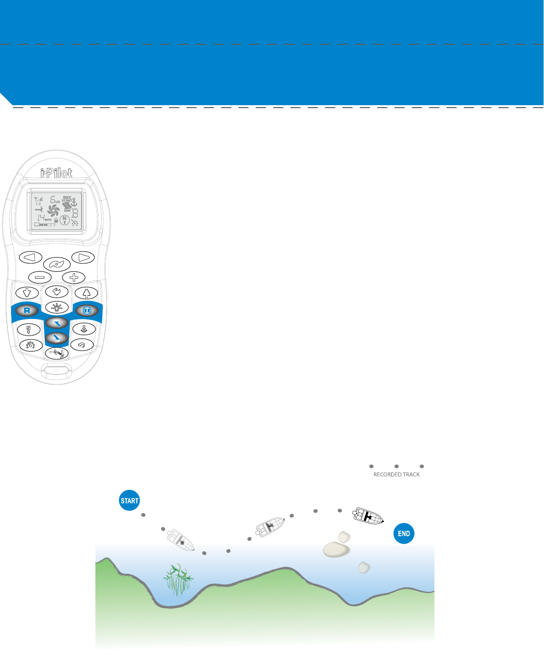
TRACK RECoRding And PLAYbACK
When the Track Record button is pressed, i-Pilot starts to record GPS position data in the form of track
points. The distance between these points varies based on the speed of the boat and the GPS signal
strength. The very fi rst track point recorded is called the start. The last point recorded is called the end.
i-Pilot sees a recorded track as a series of these track points. When a Track to Start or Track to End
button is pushed, i-Pilot will navigate to the nearest track point. Once this nearest track point is reached,
it will then follow the track points in sequence back to either the start or end based on which button was
pressed. Once the end or start track point is reached, i-Pilot automatically exits from the Track to Start
or Track to End function. During track playback, i-Pilot takes control over all steering functions; speed
can be manually controlled or the Cruise Control function can also be used. The motor speed must be
set high enough in order to stay on the track given wind, current and other external forces.
i-Pilot can also pause the recording of a track. When the recording is paused, i-Pilot temporarily stops
recording any new track points. When track recording is resumed, i-Pilot records new track points. Due
to the nature of pausing a recording, there may be a large separation distance between two track points
or two track points lying on top of one another where the pause occurred. This can cause erratic motor
steering therefore it is very important to know where the pause button was pressed and to resume the
recording just ahead of that location. If while paused, the separation distance exceeds a quarter mile, the
recording will automatically stop.
TRACK RECoRding / PLAYbACK
28 | minnkotamotors.com ©2014 Johnson Outdoors Marine Electronics, Inc.
minnkotamotors.com | 31
©2014 Johnson Outdoors Marine Electronics, Inc.
TRACK RECoRding / PLAYbACK
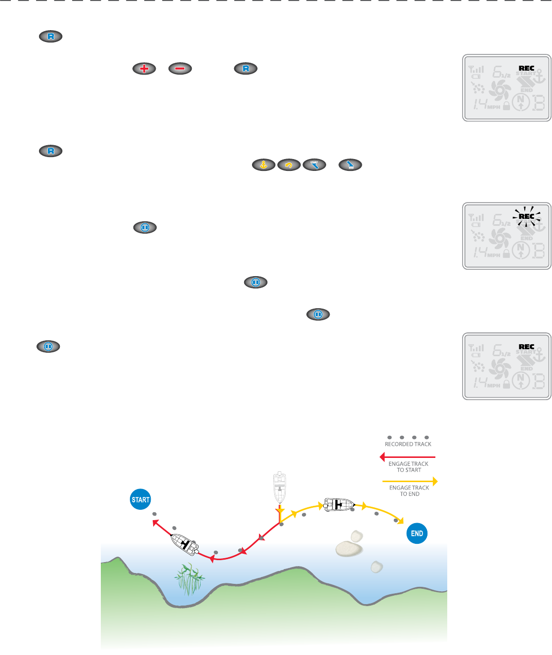
RECoRding A TRACK
1. Press on the remote.
2. The Memory Location icon will fl ash on the remote LCD for three seconds, allowing you to choose a
memory location by pressing or . Pressing again or waiting for three seconds accepts
the memory location.
3. The REC icon will be displayed on the remote LCD. Remember this will be the start point on the track.
4. Navigate the boat along the desired path or course. AutoPilot and/or Cruise Control can be used while
recording a track.
5. Press on the remote again to stop the recording. The recording will end automatically if the two-mile distance limit is reached
for the track or if one of the following buttons are pressed: or .
PAUsE And REsUmE A RECoRding
1. While recording a track press .
2. The record icon will fl ash on the remote LCD.
3. i-Pilot has now paused the recording of the track.
4. If the boat moves farther than a quarter mile from where was pressed, the recorded track will be ended and saved to the
memory location previously selected.
5. When ready to resume recording, navigate the boat just ahead of where was pushed. Failure to do this may cause erratic play
back of a track.
6. Push .
7. The record icon will stop fl ashing on the remote LCD.
8. i-Pilot is now recording again and adding to the track that was paused.
minnkotamotors.com | 29
©2014 Johnson Outdoors Marine Electronics, Inc.
32 | minnkotamotors.com ©2014 Johnson Outdoors Marine Electronics, Inc.
TRACK RECoRding / PLAYbACK
REPLAYing A TRACK
(TRACK To sTART / TRACK To End)
1. Manually navigate the boat to within a quarter mile of the saved track. Due to safety reasons, i-Pilot will not re-engage a saved track
greater than a quarter mile away.
2. Press or on the remote.
3. The Memory Location icon will fl ash on the remote LCD for three seconds, allowing you to choose a
memory location by pressing or . Pressing the button pressed in step 2 again or waiting for
three seconds accepts the memory location.
4. Adjust motor speed to desired setting to engage and navigate track automatically.
RECoRd, TRACK To End And TRACK To sTART EsCAPE
1. If or is accidentally hit, press within three seconds on the remote to cancel the command.
fooT PEdAL oPERATion
• Steering left or right and turning Advanced AutoPilot on with the foot pedal will disengage Track to Start or Track to
End.
You can switch directly between Track to Start and
Track to End. This allows you to concentrate on
productive sections of a track.
i-Pilot TIPS
30 | minnkotamotors.com ©2014 Johnson Outdoors Marine Electronics, Inc.
Toe End Speed Knob
Heel End
Mom/Off /Con Switch
Momentary Button
Directional
Indicator
ConTRoLLing sPEEd & sTEERing wiTH THE fooT PEdAL
Most controls on the foot pedal are easy to operate by either foot or hand:
To AdjUsT moToR sPEEd
Turn the speed knob clockwise to increase speed and counter-clockwise to decrease speed.
To oPERATE THE moToR in ConTinUoUs modE
Press the Mom/Off /Con switch on the side of the pedal to the Con position.
To oPERATE THE moToR in momEnTARY modE
Press the Mom/Off /Con switch on the side of the pedal to the Mom position. A toe touch to the Momentary button on the foot
pedal will now turn the motor on. Removing downward force on the Momentary button will turn the motor off .
To TURn LEfT oR RigHT
Push the toe end of the foot pedal down to turn right and push the heel end of the foot pedal down to turn left. The indicator on
the motor head shows the direction of the motor. The motor will not maintain its own heading. You must keep your foot on the
pedal to control steering during operation.
To REvERsE THE moToR
The motor always travels in the direction of the indicator. You can reverse the direction of the motor by turning the motor 180°
from straight ahead.
CAUTION:
• Switch the mom/off /con switch to “off ” when not in use. If the motor control is left on and the propeller
rotation is blocked, severe motor damage can result.
• Be sure to turn the motor off after each use.
• For safety reasons, disconnect the motor from the battery/batteries when the motor is not in use or while the
battery/batteries are being charged.
minnkotamotors.com | 31
©2014 Johnson Outdoors Marine Electronics, Inc.
Using YoUR fooTPEdAL
Momentary/Constant
"ON"/"OFF"
AutoPilot "ON"/"OFF"
Momentary On
Heel/Toe Steering
Speed Control
Spot-Lock
Right Steer /
Trim Down
Stow/Deploy/Prop
Left Steer / Trim Up
fooT PEdAL fEATUREs

Figure 1.
Figure 1.
Figure 1.
Figure 1.
Figure 1.
32 | minnkotamotors.com ©2014 Johnson Outdoors Marine Electronics, Inc.
mAnUAL sTow PRoCEdURE
In the event of a power loss or failure the following procedure shall be used to stow the motor for transport to a service center.
1. Remove Right hand sideplate
2. Using a standard screwdriver pop manual tilt knob off of tilt plates to decouple the tilt motor and tilt bracket (see figure X)
3. Pull manual trim handle located on trim housing out until shaft can be manually trimmed up.
4. Stow motor by manually tilting and trimming in until lower unit is on the ramps.
5. Secure lower unit onto the ramps using the provided emergency strap.

minnkotamotors.com | 33
©2014 Johnson Outdoors Marine Electronics, Inc.
AdjUsTmEnTs
AdjUsTing THE LifT bELT
Over the course of time the main lift belt may need small adjustments to maintain belt tension. Using a 1/8” allen wrench turn the
socket head cap screw on the bottom of the control head (see figure X) until belt is finger tight. (should be able to force finger
under belt.
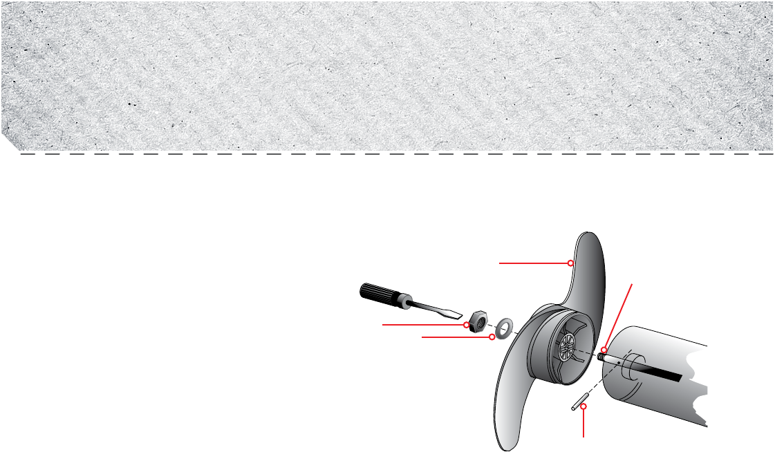
Propeller
Slot End
Drive Pin
Prop Nut
Washer
PRoPELLER REPLACEmEnT
TOOLS AND RESOURCES REQUIRED:
• 7/16” Box End Wrench
• Screwdriver (optional)
CAUTION:
Disconnect the motor from the battery
before beginning any prop work or
maintenance.
NOTE: The propeller on your motor may diff er from
the one pictured.
1. Disconnect the motor from all sources of power
prior to changing the propeller.
2. Hold the propeller and loosen the prop nut with pliers or a wrench.
3. Remove the prop nut and washer. If the drive pin is sheared or broken, you will need to hold the shaft stationary with a blade
screwdriver pressed into the slot on the end of the shaft.
4. Turn the old prop to horizontal (as illustrated) and pull it straight off . If drive pin falls out, push it back in.
5. Align the new propeller with the drive pin.
6. Install the prop washer and prop nut.
7. Tighten the prop nut 1/4 turn past snug [25-35 inch lbs.] Do not over tighten as this can damage the prop.
gEnERAL mAinTEnAnCE
1. After use, the entire motor should be rinsed with freshwater, then wiped down with a cloth dampened with an aqueous based
silicone spray. This series of motors is not equipped for saltwater exposure.
2. The propeller must be inspected and cleaned from weeds and fi shing line after every use.
Fishing line and weeds can get behind the prop, damage the seals and allow water to enter the motor.
3. Verify the prop nut is secure each time the motor is used.
4. To prevent accidental damage during transportation or storage, disconnect the battery whenever the motor is off of the water.
For prolonged storage, lightly coat all metal parts with an aqueous based silicone spray.
5. For maximum battery life recharge the battery(s) as soon as possible after use. For maximum motor performance restore
battery to full charge prior to use.
6. Keep battery terminals clean with fi ne sandpaper or emery cloth.
7. The propeller is designed to provide weed free operation with very high effi ciency. To maintain this top performance, the
leading edge of the blades must be kept smooth. If they are rough or nicked from use, restore to smooth by sanding with fi ne
sandpaper.
34 | minnkotamotors.com ©2014 Johnson Outdoors Marine Electronics, Inc.
sERviCE & mAinTEnAnCE

Propeller
Slot End
Drive Pin
Prop Nut
Washer
PRoPELLER REPLACEmEnT
TOOLS AND RESOURCES REQUIRED:
• 7/16” Box End Wrench
• Screwdriver (optional)
CAUTION:
Disconnect the motor from the battery
before beginning any prop work or
maintenance.
NOTE: The propeller on your motor may diff er from
the one pictured.
1. Disconnect the motor from all sources of power
prior to changing the propeller.
2. Hold the propeller and loosen the prop nut with pliers or a wrench.
3. Remove the prop nut and washer. If the drive pin is sheared or broken, you will need to hold the shaft stationary with a blade
screwdriver pressed into the slot on the end of the shaft.
4. Turn the old prop to horizontal (as illustrated) and pull it straight off . If drive pin falls out, push it back in.
5. Align the new propeller with the drive pin.
6. Install the prop washer and prop nut.
7. Tighten the prop nut 1/4 turn past snug [25-35 inch lbs.] Do not over tighten as this can damage the prop.
gEnERAL mAinTEnAnCE
1. After use, the entire motor should be rinsed with freshwater, then wiped down with a cloth dampened with an aqueous based
silicone spray. This series of motors is not equipped for saltwater exposure.
2. The propeller must be inspected and cleaned from weeds and fi shing line after every use.
Fishing line and weeds can get behind the prop, damage the seals and allow water to enter the motor.
3. Verify the prop nut is secure each time the motor is used.
4. To prevent accidental damage during transportation or storage, disconnect the battery whenever the motor is off of the water.
For prolonged storage, lightly coat all metal parts with an aqueous based silicone spray.
5. For maximum battery life recharge the battery(s) as soon as possible after use. For maximum motor performance restore
battery to full charge prior to use.
6. Keep battery terminals clean with fi ne sandpaper or emery cloth.
7. The propeller is designed to provide weed free operation with very high effi ciency. To maintain this top performance, the
leading edge of the blades must be kept smooth. If they are rough or nicked from use, restore to smooth by sanding with fi ne
sandpaper.
minnkotamotors.com | 35
©2014 Johnson Outdoors Marine Electronics, Inc.
fAQ

1. Motor fails to run or lacks power:
• Check battery connections for proper polarity.
• Make sure terminals are clean and corrosion free. Use fi ne sandpaper or emery cloth to clean terminals.
• Check battery water level. Add water if needed.
2. Motor loses power after a short running time:
• Check battery charge. If low, restore to full charge.
3. Motor is diffi cult to steer:
• Check steering cables for proper tension. Adjust as necessary.
4. You experience prop vibration during normal operation:
• Remove and rotate the prop 180°. See removal instructions in the Propeller Replacement Section.
5. Experiencing interference with your fi shfi nder:
• You may, in some applications, experience interference in your depth fi nder display. We recommend that you use a seperate
deep cycle marine battery for your trolling motor and that you power the depth fi nder from the starting/cranking battery. If
problems still persist, call our service department at 1-800-227-6433.
NOTE: For all other malfunctions, visit an authorized service center. You can search for an Authorized Service Center in your area
by visiting our Authorized Service page, found online at minnkotamotors.com, or by calling our customer service number at
800-227-6433.
1. Motor fails to deploy:
2. Motor fails to stow:
3. Motor fails to trim:
4. Motor fails to deploy:
5. Motor fails to stow:
6. Motor fails to deploy:
7. Motor fails to stow:
8. Motor fails to trim:
36 | minnkotamotors.com ©2014 Johnson Outdoors Marine Electronics, Inc.
TRoUbLEsHooTing

foR fURTHER TRoUbLEsHooTing And REPAiR
We off er several options to help you troubleshoot and/or repair your product. Please read through the options listed below.
fREQUEnTLY AsKEd QUEsTions
We have FAQs available on our website to help answer all of your Minn Kota questions. Visit minnkotamotors.com and click on
“Frequently Asked Questions” to fi nd an answer to your question.
CALL Us (foR U.s. And CAnAdA)
Our consumer service representatives are available Monday – Friday between 7:00 a.m. – 4:30 p.m. CST at 800-227-6433.
If you are calling to order parts, please have the 11-character serial number from your product, specifi c part numbers, and credit
card information available. This will help expedite your call and allow us to provide you with the best consumer service possible.
You can reference the parts list located in your manual to identify the specifi c part numbers.
EmAiL Us
You can email our consumer service department with questions regarding your Minn Kota products. To email your question, visit
minnkotamotors.com and click on “Support”.
AUTHoRiZEd sERviCE CEnTERs
Minn Kota has over 300 authorized service centers in the United States and Canada where you can purchase parts or get your
products repaired. Please visit our Authorized Service Center page on our website to locate a service center in your area.
minnkotamotors.com | 37
©2014 Johnson Outdoors Marine Electronics, Inc.
TRoUbLEsHooTing

38 | minnkotamotors.com ©2014 Johnson Outdoors Marine Electronics, Inc.
PARTs diAgRAm

minnkotamotors.com | 39
©2014 Johnson Outdoors Marine Electronics, Inc.
PARTs diAgRAm

EnviRonmEnTAL ComPLiAnCE sTATEmEnT:
It is the intention of JOME to be a responsible corporate citizen, operating in compliance with known and applicable
environmental regulations, and a good neighbor in the communities where we make or sell our products.
wEEE diRECTivE:
EU Directive 2002/96/EC “Waste of Electrical and Electronic Equipment Directive (WEEE)” impacts most distributors, sellers,
and manufacturers of consumer electronics in the European Union. The WEEE Directive requires the producer of consumer
electronics to take responsibility for the management of waste from their products to achieve environmentally responsible
disposal during the product life cycle.
WEEE compliance may not be required in your location for electrical & electronic equipment (EEE), nor may it be required
for EEE designed and intended as fi xed or temporary installation in transportation vehicles such as
automobiles, aircraft, and boats. In some European Union member states, these vehicles are considered
outside of the scope of the Directive, and EEE for those applications can be considered excluded from the
WEEE Directive requirement.
This symbol (WEEE wheelie bin) on product indicates the product must not be disposed of with other
household refuse. It must be disposed of and collected for recycling and recovery of waste EEE. Johnson
Outdoors Inc. will mark all EEE products in accordance with the WEEE Directive. It is our goal to comply
in the collection, treatment, recovery, and environmentally sound disposal of those products; however, these requirement do
vary within European Union member states. For more information about where you should dispose of your waste equipment for
recycling and recovery and/or your European Union member state requirements, please contact your dealer or distributor from
which your product was purchased.
disPosAL:
Minn Kota motors are not subject to the disposal regulations EAG-VO (electric devices directive) that implements the WEEE
directive. Nevertheless never dispose of your Minn Kota motor in a garbage bin but at the proper place of collection of your local
town council.
Never dispose of battery in a garbage bin. Comply with the disposal directions of the manufacturer or his representative and
dispose of them at the proper place of collection of your local town council.
WARNING:
This product contains chemical(s) known to the state of California to cause cancer and/or reproductive toxicity.
40 | minnkotamotors.com ©2014 Johnson Outdoors Marine Electronics, Inc.
ComPLiAnCE sTATEmEnTs

EnviRonmEnTAL ComPLiAnCE sTATEmEnT:
It is the intention of JOME to be a responsible corporate citizen, operating in compliance with known and applicable
environmental regulations, and a good neighbor in the communities where we make or sell our products.
wEEE diRECTivE:
EU Directive 2002/96/EC “Waste of Electrical and Electronic Equipment Directive (WEEE)” impacts most distributors, sellers,
and manufacturers of consumer electronics in the European Union. The WEEE Directive requires the producer of consumer
electronics to take responsibility for the management of waste from their products to achieve environmentally responsible
disposal during the product life cycle.
WEEE compliance may not be required in your location for electrical & electronic equipment (EEE), nor may it be required
for EEE designed and intended as fi xed or temporary installation in transportation vehicles such as
automobiles, aircraft, and boats. In some European Union member states, these vehicles are considered
outside of the scope of the Directive, and EEE for those applications can be considered excluded from the
WEEE Directive requirement.
This symbol (WEEE wheelie bin) on product indicates the product must not be disposed of with other
household refuse. It must be disposed of and collected for recycling and recovery of waste EEE. Johnson
Outdoors Inc. will mark all EEE products in accordance with the WEEE Directive. It is our goal to comply
in the collection, treatment, recovery, and environmentally sound disposal of those products; however, these requirement do
vary within European Union member states. For more information about where you should dispose of your waste equipment for
recycling and recovery and/or your European Union member state requirements, please contact your dealer or distributor from
which your product was purchased.
disPosAL:
Minn Kota motors are not subject to the disposal regulations EAG-VO (electric devices directive) that implements the WEEE
directive. Nevertheless never dispose of your Minn Kota motor in a garbage bin but at the proper place of collection of your local
town council.
Never dispose of battery in a garbage bin. Comply with the disposal directions of the manufacturer or his representative and
dispose of them at the proper place of collection of your local town council.
WARNING:
This product contains chemical(s) known to the state of California to cause cancer and/or reproductive toxicity.
minnkotamotors.com | 41
©2014 Johnson Outdoors Marine Electronics, Inc.
ComPLiAnCE sTATEmEnTs
FCC Compliance
This device complies with Part 15 of the FCC rules.
Operation is subject to the following two conditions:
1. This device may not cause harmful interference.
2. This device must accept any interference that may be received, including interference that may cause undesired operation.
Changes or modifcations not expressly approved by Johnson Outdoors Marine Electronics, Inc. could void the user’s authority to
operate this equipment.
This product meets the applicable Industry Canada's license exempt RSSs. Operation is subject to the following two conditions:
(1) this device may not cause interference, and (2) this device must accept any interference, including interference that may cause
undesired operation of the device.
Le présent materiel est conforme aux CNR exempts de licence d'Industrie Canada. Son fonctionnement est soumis
aux deux conditions suivantes: (1) cet appareil ne peut pas provoquer d'interférences, et (2) cet appareil doit accepter toute
interférence, y compris celles susceptibles de provoquer le fonctionnement du dispositif.
Note: This equipment has been tested and found to comply with the limits for a Class B digital device, pursuant to part 15 of the
FCC Rules. These limits are designed to provide reasonable protection against harmful interference in a residential installation.
This equipment generates, uses and can radiate radio frequency energy and, if not installed and used in accordance with the
instructions, may cause harmful interference to radio communications. However, there is no guarantee that interference will not
occur in a particular installation. If this equipment does cause harmful interference to radio or television reception,
which can be determined by turning the equipment of and on, the user is encouraged to try to correct the
interference by one or more of the following measures:
• Reorient or relocate the receiving antenna.
• Increase the separation between the equipment and receiver.
• Connect the equipment into an outlet on a circuit different from that to which the receiver is connected.
• Consult the dealer or an experienced radio/TV technician for help
To minimize RF exposure, maintain at least 20cm (7.87in.) of separation between your body and the motor.
• IC: 4397A-ULTERRAIP15
• FCC ID: T62-ULTERRAIP15
• IC: 4397A-ULTERRAIP20
• FCC ID: T62-ULTERRAIP20
Carrier frequency:
US/Canada/Australia: 915MHz
918MHz
921MHz
European: 864MHz
867MHz
870MHz
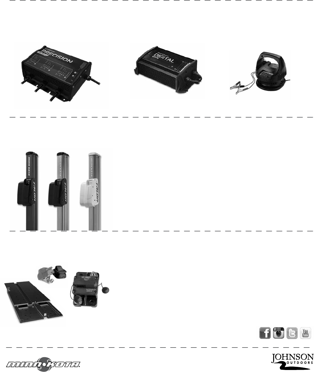
A Johnson Outdoors Company
Minn Kota Consumer & Technical Service
Johnson Outdoors Marine Electronics, Inc.
PO Box 8129
Mankato, MN 56001
121 Power Drive
Mankato, MN 56001
Phone (800) 227-6433
Fax (800) 527-4464
minnkotamotors.com
©2014 Johnson Outdoors Marine Electronics, Inc.
All rights reserved.
For a complete listing of Minn Kota accessories, visit minnkotamotors.com
• 60-Amp Circuit Breaker
• Mounting Brackets
• Stabilizer Kits
• Extension Handles
• Battery Connectors
• Battery Boxes
• Quick Connect Plugs
RECommEndEd ACCEssoRiEs
on-boARd & PoRTAbLE bATTERY CHARgERs
Stop buying new batteries and start taking care of the ones you’ve got. Many chargers can actually damage your battery
over time – creating shorter run times and shorter overall life. Digitally controlled Minn Kota chargers are designed to provide the
fastest charge that protect and extend battery life.
TALon sHALLow wATER AnCHoR
Talon deploys faster, holds stronger and runs quieter than any other shallow water anchor. Available in depths up to 12’ and bold color
options, it boasts an arsenal of features and innovations that no other anchor can touch:
minn KoTA ACCEssoRiEs
We offer a wide variety of trolling motor accessories, including:
mK212dmK345PC mK105P
Follow us:
• Vertical, multi-stage deployment
• User-Selectable Anchoring Modes
• 2x Anchoring Force
• Fast Deploy
• Auto Up/Down
• Triple Debris shields*
• Built-In Wave Absorption
• Noise Dissipation
• Versatile Adjustments
*available on 10’ and 12’ models only
Part #2207101 Rev A 7/14
ECN #####