Johnson and Johnson Surgical Vision SIGACPM Advanced Control Pedal Master User Manual Whitestar OM
Abbott Medical Optics Advanced Control Pedal Master Whitestar OM
UserManual.wiki
>
Johnson and Johnson Surgical Vision
>
SIGACPM User Manual
Users Manual
Navigation menu
Upload a User Manual
Namespaces
Wiki Guide
HTML
PDF
Info
Views
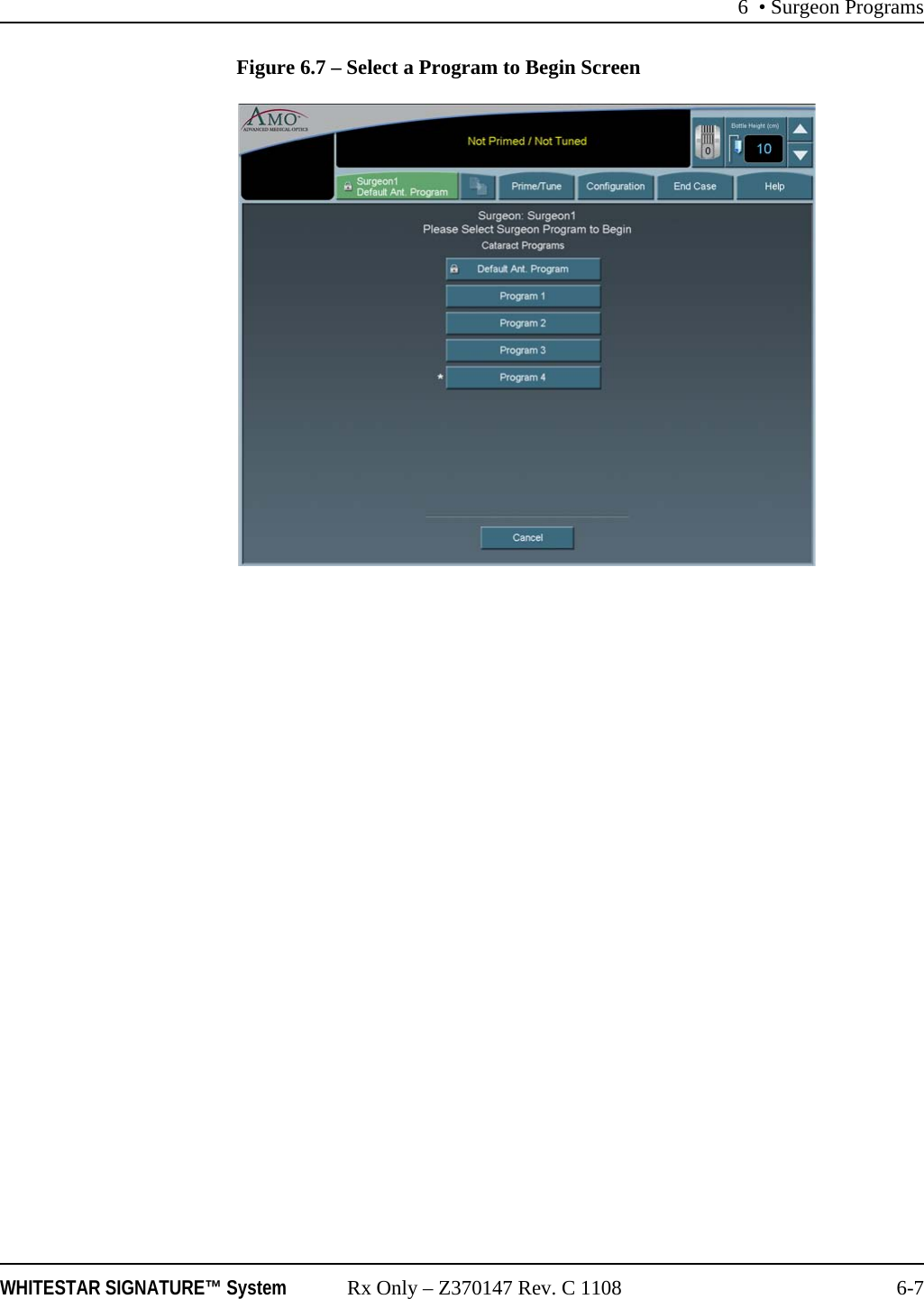
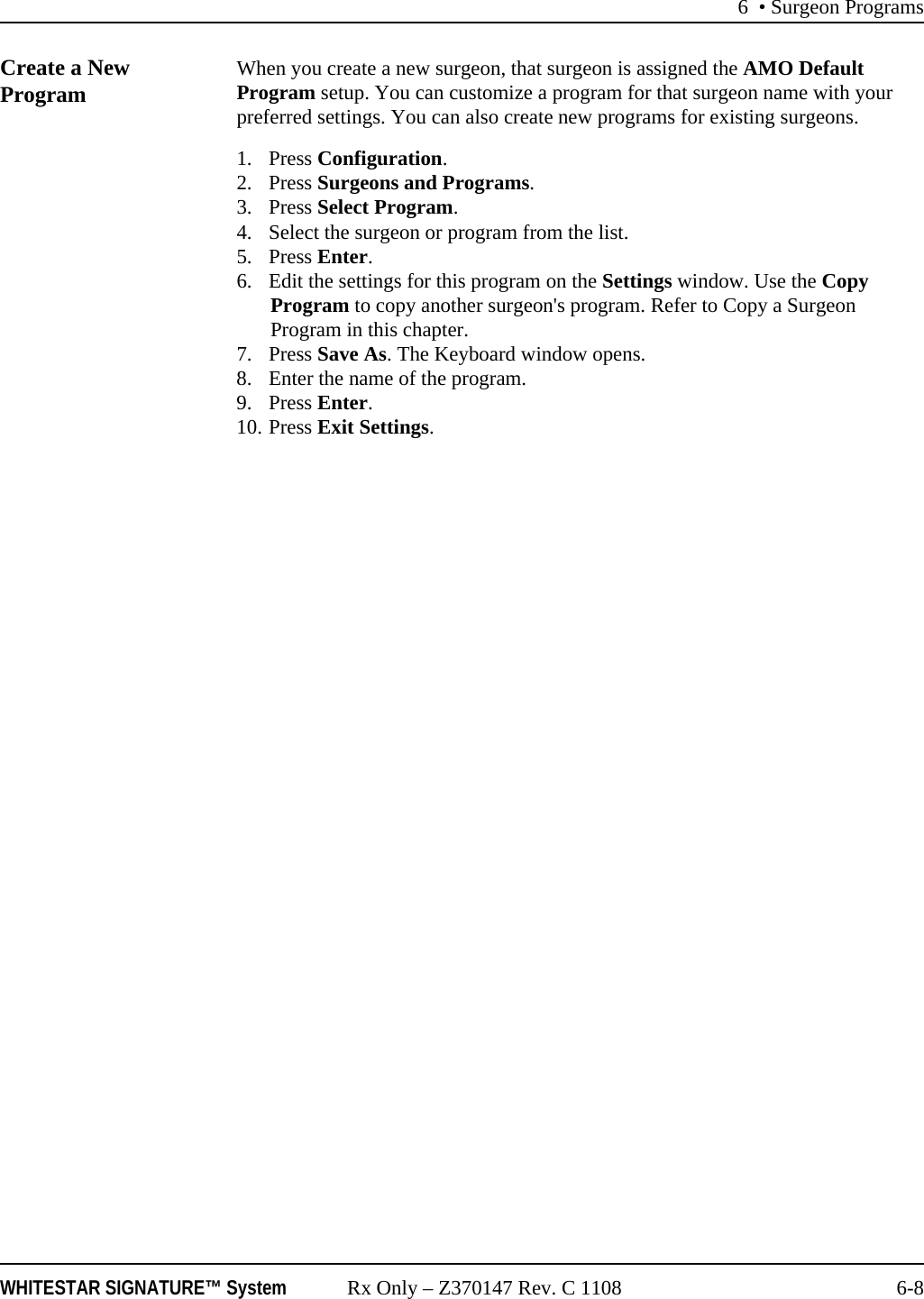
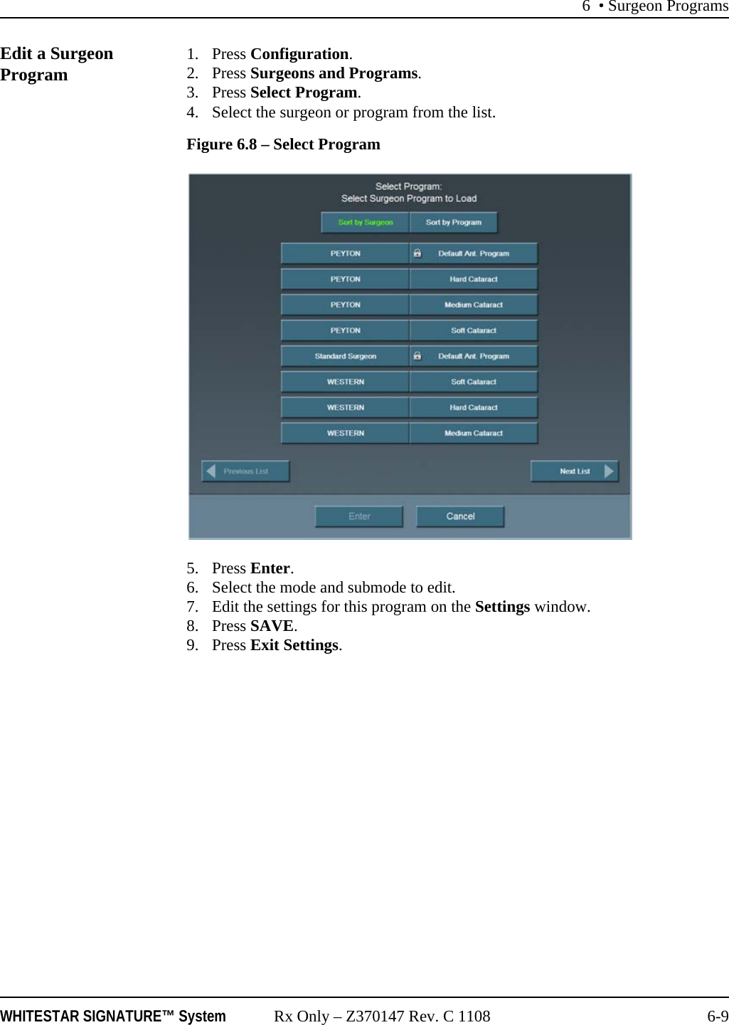
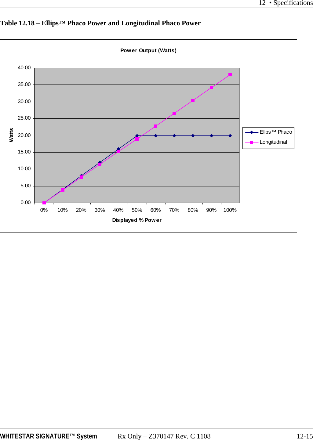
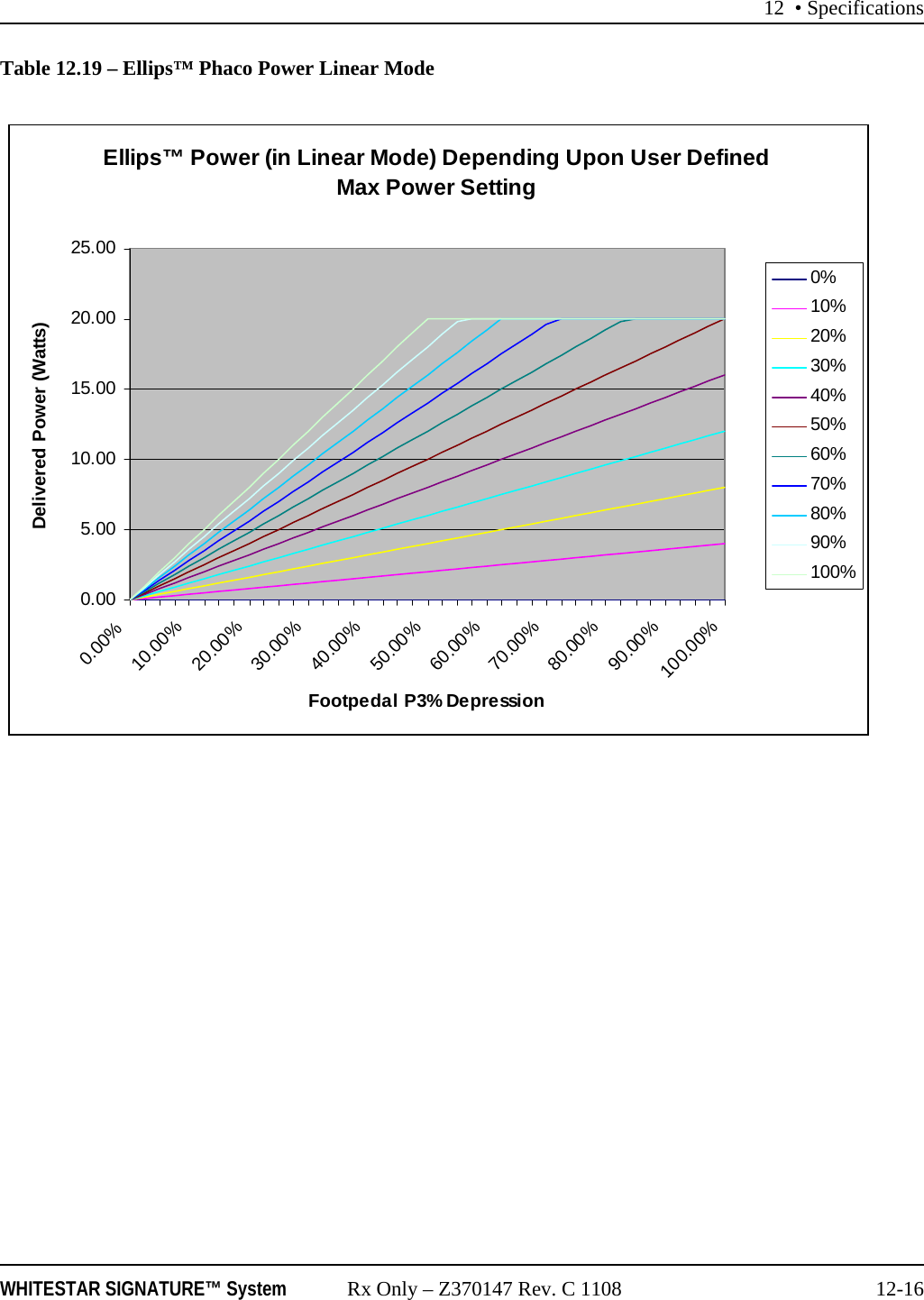
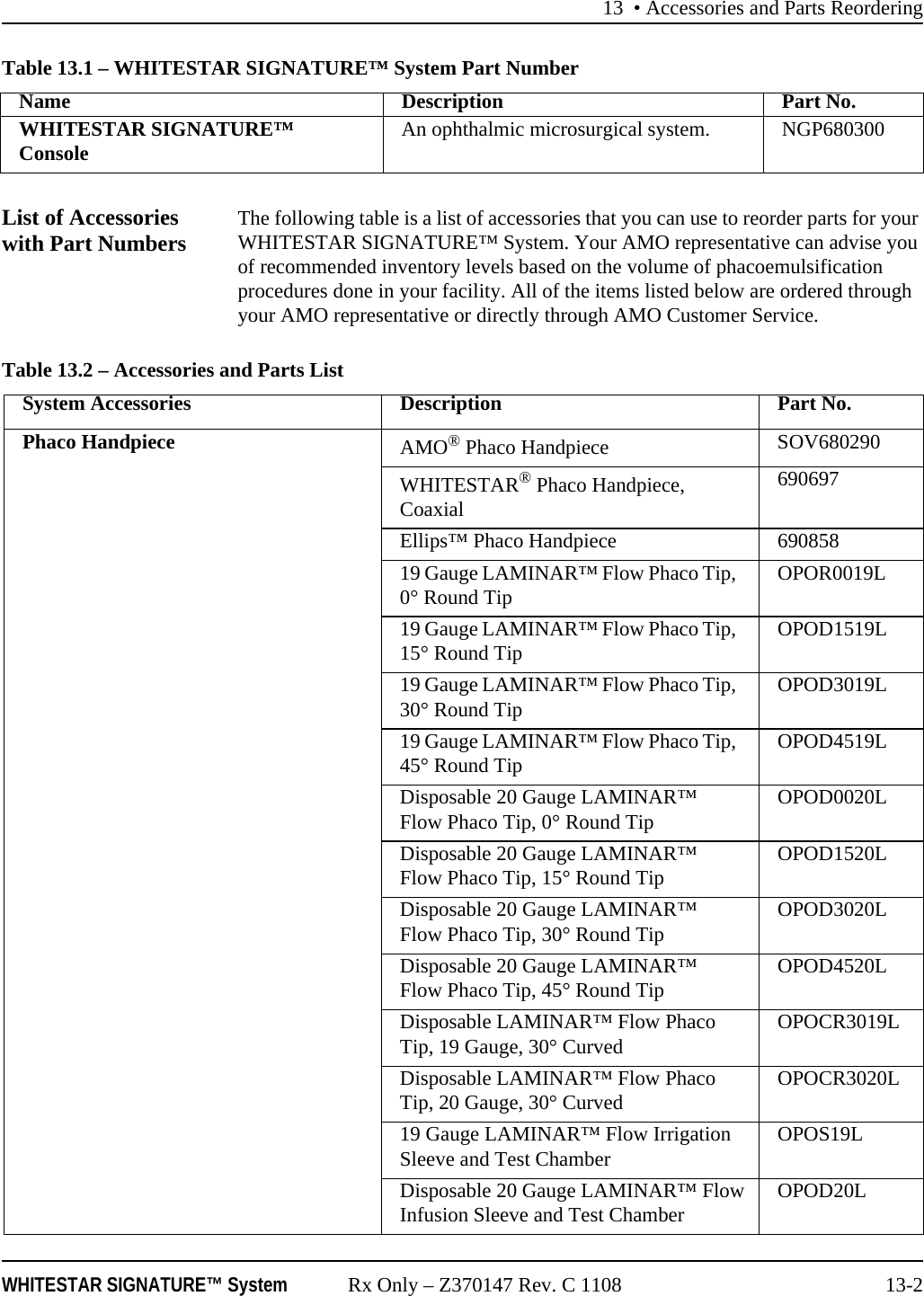
User Manual
Discussion / Help
Navigation