Johnson and Johnson Surgical Vision SIGREM Wireless Remote Control System with Bluetooth User Manual 03 Whitestar OM
Abbott Medical Optics Wireless Remote Control System with Bluetooth 03 Whitestar OM
Users manual

WHITESTAR SIGNATURE ™
OWNER’S AND
OPERATOR’S MANUAL
Manufactured By:
Advanced Medical Optics, Inc.
1700 E. St. Andrew Place
Santa Ana, CA 92705
USA
1-800-449-3060
www.amo-inc.com
For Order Placement
of Surgical Products
(IOLs and Phaco Supplies)
Call 1-800-366-6554 (USA)
AMO Ireland
Dublin 4
Ireland,
For Phaco Returns or Technical
Service
Call 1-800-449-3060 (USA)
All returns must be accompanied by a
RGA#
(Returned Goods Authorization)
0050
Rx Only – Z370101 Ver. 5.0 0807
© 2007 Advanced Medical Optics, Inc.
Trademarks
AMO, the ADVANCED MEDICAL OPTICS logo, FUSION, LAMINAR, OCCLUSION MODE,
SOVEREIGN, WHITESTAR and WHITESTAR SIGNATURE are trademarks of Advanced
Medical Optics, Inc.
SOLO is a trademark of Micro-Surgical Technology, Inc.
Compliance
In accordance with:
• IEC/EN 60601-1

WHITESTAR SIGNATURE™ System Rx Only – Z370101 Rev. 05 0807 3-1
Safety Precautions
Warnings
Symbol Definitions
System Disposal
Setup Sequence – Anterior Segment Surgery
Footpedal
Programmable Power IV Pole
Wireless Remote Control (Optional)
Surgical Media Center (SMC) (Optional)
Shutdown Sequence – Anterior Segment Surgery
3SYSTEM SETUP

3 • System Setup
WHITESTAR SIGNATURE™ System Rx Only – Z370101 Rev. 05 0807 3-2
Safety Precautions Now that the system is set up and you have verified that all of the functions are
operating properly, you are almost ready to use your WHITESTAR
SIGNATURE™ System.
Read the following Safety Precautions and Warnings carefully before you use the
WHITESTAR SIGNATURE™ System in surgery.
1. The WHITESTAR SIGNATURE™ System is equipped with 3-prong plugs
which must be plugged into an outlet with a ground receptacle.
If the plug does not fit the outlet, contact an electrician. DO NOT modify or
remove the ground pin.
2. Do not use extension cords with your machine.
3. Do not overload your electrical receptacle (outlet).
4. If the cord or plug is damaged, do not use the instrument. An electric shock or
fire hazard can result. Call AMO customer service to order a new cord.
5. The instrument has ventilation openings at the rear of the console to allow
ambient air intake and the release of heat generated during operation. If the
openings are blocked, heat build-up can cause system failures which can result
in a fire hazard.
6. Do not try to move the WHITESTAR SIGNATURE™ System cart on deep
pile carpets or over objects on the floor such as cables and power cords.
7. Take care not to trip over power and footpedal cords. Keep power and
footpedal cords away from the surgical area.
8. Do not try to lift the WHITESTAR SIGNATURE™ System cart.
9. Do not place the instrument on uneven or sloped surfaces.
10. Do not use disposables, accessories or other surgical instruments that are not
designed for this system. Use only parts recommended by AMO to achieve
optimum performance and safety.
11. Do not operate the WHITESTAR SIGNATURE™ System in a condensing
environment. Take care to protect the instrument from fluid sprays or fluid
buildup.
12. To protect the patient from contaminated fluids or handpieces, use only:
• sterile tubing cassettes
• sterile irrigation fluid
• sterile handpieces
13. Use caution when you extend, retract or swivel the Mayo stand articulating
arm. Stay clear of the hinged hardware.
14. Use caution when you use handpieces with sharp edges or pointed tips.

3 • System Setup
WHITESTAR SIGNATURE™ System Rx Only – Z370101 Rev. 05 0807 3-3
15. Always replace the tubing cassette between cases.
16. Wrap the excess power cord neatly around the cord wrap on the back of the
console.
Changing Irrigation
Use extreme caution when you lower or raise the balanced salt solution bottle to
decrease or increase fluid flow and pressure. If you lower the bottle too much it can
cause the anterior chamber to collapse. If you raise the bottle too high it can cause
the anterior chamber to deepen. To make sure that the bottle height does not go too
high, you can set the maximum bottle height on the Diagnostics screen.
Note: Use a new bottle of balanced salt solution at the start of each case.
Phacoemulsification without Adequate Irrigation
Operating phacoemulsification without an adequate flow can result in an elevated
temperature of the tip and subsequent damage to the eye tissue or could cause the
chamber to collapse. Confirm that there is irrigation flow before you initiate
phacoemulsification. A tight wound or the angle of the needle next to the wound
can also constrict the irrigation flow by pinching the coaxial irrigation sleeve
assembly on the needle of the phaco handpiece.
Power Failure during Surgery
If there is a loss of power during a procedure, you need to:
• Withdraw the handpiece from the eye
• Release the footpedal to Position 0
• When power is restored, select Prime/Tune to reprime the fluids or use Bypass
• Select the mode you were using (PHACO, IA, Vitrectomy or Diathermy)
Connecting Handpieces
It is very important that the electrical connectors on the handpieces are completely
dry before they are connected to the WHITESTAR SIGNATURE™ System
receptacles. You can receive a “Handpiece Ground Fault Error” message if the
connector is wet.
Handling the Phaco Handpiece
The phaco handpiece is a very delicate instrument and must be handled with
EXTREME care. If the handpiece is dropped or received any other significant
impact, the handpiece will not work properly. The ultrasonic titanium phaco tip
must never touch any solid material while in use.
Always flush the handpiece immediately following surgery.
See cleaning instructions given in Chapter 9, “Care and Cleaning”.
Handpieces can be extremely hot immediately after sterilization. Use care and
caution when handling.

3 • System Setup
WHITESTAR SIGNATURE™ System Rx Only – Z370101 Rev. 05 0807 3-4
Phaco and Vitrectomy Operation
The phaco handpiece and vitrectomy cutter must never be activated with the tips
exposed to air. If the tips are activated in the air, the useful life of the handpiece and
cutter is reduced. If power is to be introduced to the phaco handpiece or vitrectomy
cutter, the tips must be in a test chamber filled with a balanced salt solution, in a
container of balanced salt solution, or in the patient's eye.
Vitrectomy
Failure to properly attach the tubing to the appropriate vacuum or pressure source
can affect the vitrectomy cutter operation. Be sure to read the vitrectomy cutter
package insert for correct assembly and connection procedures.
Diathermy
When you enter the Diathermy mode, an audible tone should be heard. Also,
whenever diathermy power is applied, an audible tone should be heard.
The diathermy cable must be checked periodically for damage. If the cable shows
signs of damage, replace the cable immediately with the same type of cable. Use of
other types of cables can affect the diathermy performance.
During surgery, the diathermy output power must be as low as possible for the
intended purpose. AMO recommends the 30% setting to start.
The diathermy cable must be positioned in such a way that contact with the patient
or other leads is avoided. Grounded or ungrounded metal parts must not come in
contact with the patient when diathermy is used.
For proper operation of the diathermy, replace the handpiece with the same type.
Programmable Power IV Pole
Do not exceed the maximum weight of two 500 ml balanced salt solution bottles on
the IV pole bottle holder.
Wireless Remote Control
This device complies with part 15 of the FCC (Federal Communications
Commission) Rules. Operation is subject to the following two conditions:
1. This device may not cause harmful interference.
2. This device must accept any interference received, including interference that
may cause undesired operation.
Any changes or modifications not expressly approved by Advanced Medical
Optics, Inc. can void the user's authority to operate the equipment.

3 • System Setup
WHITESTAR SIGNATURE™ System Rx Only – Z370101 Rev. 05 0807 3-5
Note: This equipment has been tested and found to comply with the limits for a
Class A digital device, pursuant to part 15 of the FCC Rules. These limits are
designed to provide reasonable protection against harmful interference when
the equipment is operated in a commercial environment. This equipment
generates, uses, and can radiate radio frequency energy and, if not installed
and used in accordance with the instruction manual, may cause harmful
interference to radio communications. Operation of this equipment in a
residential area is likely to cause harmful interference in which case the user
will be required to correct the interference at his own expense.
Warnings
WARNING: All personnel who might operate this equipment must read
and understand the instructions in this manual before the system is used. Failure to
do so might result in the improper operation of the system. This device is only to be
used by a trained licensed physician.
WARNING: DO NOT attempt to use the system if the system fails to
perform properly as stated in this manual.
WARNING: DO NOT use the System in the presence of flammable
anesthetics, or other flammable gases, near flammable fluids or objects, or in the
presence of oxidizing agents, as a fire could result.
WARNING: This unit might interfere with any cardiac pacemaker fitted
to the patient; therefore qualified advice must be obtained prior to such use.
WARNING: The patient must not come into contact with metal parts
which are grounded or have appreciable capacitance to ground. The use of an
antistatic mat for this purpose is recommended.
WARNING: Proper handling and disposal methods for biohazards must
be used when you dispose of the tubing cassette, Mayo stand drape and monitor
drape.
!
!
!
!
!
!

3 • System Setup
WHITESTAR SIGNATURE™ System Rx Only – Z370101 Rev. 05 0807 3-6
WARNING: Monitoring electrodes or other types of equipment must be
placed as far from those of the WHITESTAR SIGNATURE™ System as possible.
High current limiting devices are recommended for the protection of such systems.
Needle monitoring electrodes are not recommended.
WARNING: Keep the diathermy cord away from the patient and other
handpieces or leads (for example, monitoring electrodes).
WARNING: The output power selected must be as low as possible for
the intended purpose.
WARNING: Although this unit complies with all EMI standards and
requirements, it is possible that interference provided by the operation of the HIGH
FREQUENCY (HF) SURGICAL EQUIPMENT can adversely influence the
operation of other electronic equipment.
WARNING: Skin to skin contact on the patient, for example, between
the arms and the torso is not recommended. Insert dry gauze to avoid contact, as
appropriate.
Note: The unit contains no neutral electrode.
Note: The diathermy output is bipolar.
Note: It is recommended that the condition of all inter-connecting and handpiece
cables be checked on a regular basis.
WARNING: Risk of burns and fire. Do not use the System near
conductive materials such as metal bed parts, inner spring mattresses, or similar
items. Replace electrode cables on evidence of deterioration.
WARNING: Hazardous electrical output. This equipment is for use only
by qualified personnel.
!
!
!
!
!
!
!

3 • System Setup
WHITESTAR SIGNATURE™ System Rx Only – Z370101 Rev. 05 0807 3-7
WARNING: Disconnect the power before you service the equipment.
WARNING: Remove the power cord from the power outlet when the
equipment is not in use.
WARNING: Do not obstruct the power outlet so that the power cord can
be readily removed, as needed.
WARNING: Not recommended for use in condensing environments. If
exposed to a condensing environment, allow the system to equilibrate to typical
operating room conditions prior to use.
WARNING: This HIGH FREQUENCY (HF) SURGICAL
EQUIPMENT is specified for use without a NEUTRAL ELECTRODE.
WARNING: Failure of the HIGH FREQUENCY (HF) SURGICAL
EQUIPMENT could result in an unintended increase of output power.
WARNING: DO NOT try to replace the Wireless Remote Control
battery. Call your AMO Tecnical Service representative to replace the battery.
WARNING: Sterility assurance is the responsibility of the user. All non-
sterile accessories must be sterilized prior to use.
!
!
!
!
!
!
!
!
3 • System Setup
WHITESTAR SIGNATURE™ System Rx Only – Z370101 Rev. 05 0807 3-8
WARNING: Prior to using any invasive portions of the handpiece
assembly, examine under the microscope for any obvious damage, oxidation, or the
presence of foreign material. If any questionable characteristics are noted, use a
backup handpiece for surgery. Use of contaminated or damaged system accessories
can cause patient injury.
WARNING: Use of non-AMO approved products with the
WHITESTAR SIGNATURE™ System, can affect overall system performance and
is not recommended. AMO cannot be responsible for system surgical performance
if these products are utilized in surgery.
Symbol Definitions The following symbols appear on the WHITESTAR SIGNATURE™ System front
and back panels and in the software:
Table 3.1 Symbol Definitions
!
!
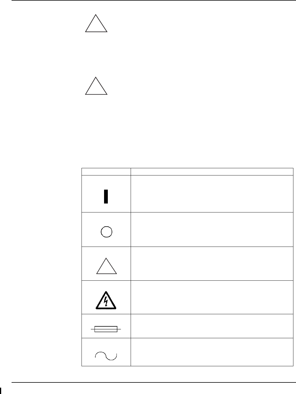
Symbol Definition
Symbol on power switch indicates Power is On.
Symbol on power switch indicates Power is Off.
Indicates that there are important operating and
maintenance instructions included in the Owner’s and
Operator’s Manual.
Indicates the presence of uninsulated high voltage inside
the instrument. Risk of electric shock. Do not remove the
instrument cover.
Indicates fuse.
Single phase alternating current.
!
3 • System Setup
WHITESTAR SIGNATURE™ System Rx Only – Z370101 Rev. 05 0807 3-9
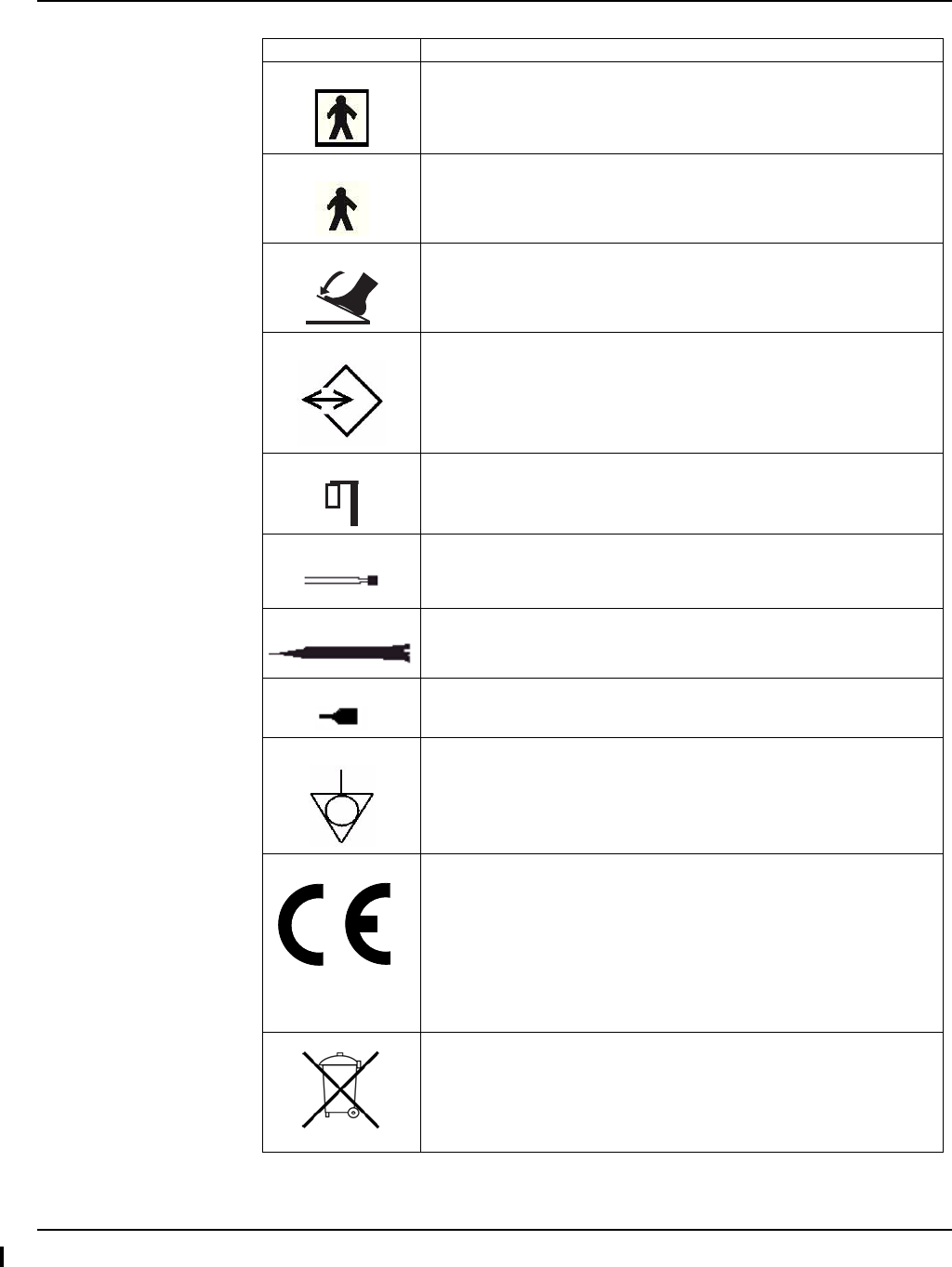
Patient applied part is isolated from earth ground.
Patient applied part is grounded OR no direct electrical
energy is involved.
Footpedal connection.
Communications Port
Programmable Power IV Pole
Diathermy Forceps
phaco Handpiece Receptacle
Vitrectomy Cutter
Potential Equalizer
Indicates compliance with the Medical Device Directive.
Separate Disposal/Collection Required
Symbol Definition
0050
3 • System Setup
WHITESTAR SIGNATURE™ System Rx Only – Z370101 Rev. 05 0807 3-10
System Disposal WEEE
The electronic components of the WHITESTAR SIGNATURE™ System are
subject to the European Union Directive 2002/96/EC on Waste Electrical and
Electronic Equipment. This directive applies to all electronic equipment in the
European Union only.
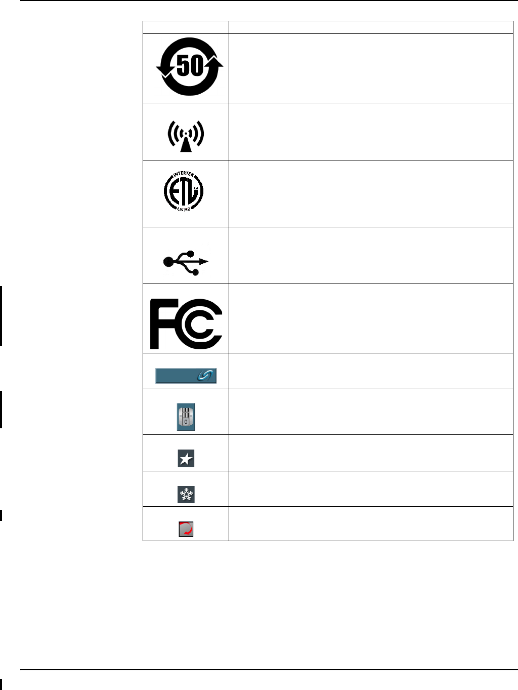
Environment Friendly Use Period in Years (RoHS)
Indicates compliance with IEC 60601-1-2:2001,
“Electromagnetic Compatibility Requirements and Tests
for Medical Electrical Equipment.”
ETL Listed Mark issued to those products that have met the
requirements of product safety standards for the United
States and Canada. (ETL formerly Edison Testing
Laboratory)
Universal Serial Bus (USB) Port
Federal Communications Commission (FCC)
The FCC regulates interstate and international
communications by radio, television, wire, satellite and
cable under the FCC’s jurisdiction.
FUSION™ Mode button used to open the CASE settings
screen.
Shows the position of the footpedal when the footpedal is
pressed. The number shown changes when the position is
changed.
WHITESTAR™ Technology is On.
WHITESTAR™ Technology is On and ICE Pulse Shaping
is On.
Torsional Technology is active (on).
Symbol Definition

3 • System Setup
WHITESTAR SIGNATURE™ System Rx Only – Z370101 Rev. 05 0807 3-11
The disposal to municipal waste is prohibited for electronic equipment subject to
this directive; this equipment must be treated or recycled. Each component that is
subject to this regulation is marked on the component itself with the following
symbol:
In some cases where the component’s size prohibits marking (such as handpieces)
the marking can be found on the directions for use and the warranty. Treatment
and/or recycling of the electronic equipment are provided at no cost to you. Please
see the contact information below for disposition of unwanted AMO electronic
equipment.
For disposal of your unit, contact your local AMO subsidiary or the AMO service
center nearest you.
Belgium
Distributor
De Ceunynck Medical
nv/sa
Kontichsesteenweg 36
B-2630 AARTSELAAR
Belgium
Denmark
Distributor
AMO Denmark ApS
c/o Advanced Medical Optics
Norden AB
Johanneslundsvagen 2
194 81 Upplands Vasby
Sweden
Finland
AMO Norden AB
Vantaa/Finland
Rajatorpantie 41 C, 3. krs
FIN-01640 Vantaa
Finland
Phone: +358 9 8520 2192
France
AMO France SAS
E. Space Park Batiment D
45 Allee des Ormes
06250 Mougins
France
Phone: +33 49 22 87 228
Germany
AMO Germany GmbH
Rudolf-Plank_Strasse 31
D-76275 Ettlingen
Germany
Phone: +49 7243 729 444 (Hotline)
Greece
Distributor
Alvia S.A.
18th Klm Marathonos Av.
153 51 Pallini Attikis
Athens
Greece

3 • System Setup
WHITESTAR SIGNATURE™ System Rx Only – Z370101 Rev. 05 0807 3-12
Ireland
AMO Ireland
Sweepstakes Sentre
Ballsbridge
Dublin 4
Ireland
Italy
AMO Italy Srl
Via Pio Emmanuelli, n.1
00143 Rome
Italy
Phone: +39 06 51 29 61
Netherlands
AMO Netherlands B.V.
Business Centre
Rhijnhuysen
Edisonbaan 14 C-3
3439 MN Nieuwegein
The Netherlands
Phone: +31 30 75 03 740
Norway
Distributor
Advanced Medical Optics
Norway AS
c/o Advanced Medical Optics
Norden AB
Johanneslundsvagen 2
194 81 Upplands Vasby
Sweden
Portugal
Distributor
Medotec
Distribuicao de Medicamentos LDA
Av. dos Bomberios
Voluntarios 40-8
Alges, 1495 Lisboa
Portugal
Spain
Advanced Medical Optics
Spain, S.L.
c/Dr. Zamenhof, n. 22, 4B
28027 Madrid
Spain
Phone: +34 9176 88 000
Sweden
Advanced Medical Optics
Norden AB
Johanneslundsvagen 2
194 81 Upplands Vasby
Sweden
Switzerland
AMO Switzerland GmbH
Feldmoosstrasse 6
CH-8853 Lachen
Switzerland
Phone: +41 554 51 07 80
United Kingdom
AMO United Kingdom Ltd
Jupiter House
Mercury Park
Woodburn Green
High Wycombe
Buckinghamshire
HP10 0HH United Kingdom
Phone: +44 162 85 51 600

3 • System Setup
WHITESTAR SIGNATURE™ System Rx Only – Z370101 Rev. 05 0807 3-13
RoHS (Restriction of Hazardous Substances)
For Chinese Regulation: Administrative Measure on the Control of Pollution
Caused by Electronic Information Products
Setup Sequence –
Anterior Segment
Surgery
The following is a general overview of the steps to be taken to prepare the
WHITESTAR SIGNATURE™ System for surgery:
1. Connect the WHITESTAR SIGNATURE™ System power cord to the rear of
system. Plug the power cord into a grounded power outlet.
2. Connect the footpedal to the rear panel receptacle.
3. Connect the compressed air line to the compressed air receptacle (optional).
4. Turn the system On at the back of the console.
5. Press the On/Off button on the Touch Screen monitor.
6. After completion of the Start Up Self Test, select the surgeon and program.
7. Install the tubing cassette, attach the required accessories (phaco, vitrectomy or
diathermy handpieces) and set up the tubing.
8. Prime and tune the handpieces. (Refer to Chapter 4, Equipment Operation,
Prime/Tune.)
Table 3.2 Names and Content of Toxic and Hazardous Substances or
Elements
Parts Name Toxic and Hazardous Substances or Elements
Pb Hg Cd Cr6+ PBB PBDE
Housing x o o x o o
Power Supply x o o x x x
Motherboard xooo x x
Rear Panel
Assembly Board
xoox x x
Pneumatics x o o x o o
LCD xxoo x x
Base Unit x o o o x x
Fluidics xoox o o
o: Indicates that this toxic or hazardous substance contained in all of the
homogeneous materials for this part is below the limit requirement in SJ/
T11363-2006
x: Indicates that this toxic or hazardous substance contained in at least one of
the homogeneous materials used for this part is above the limit requirement in
SJ/T11363-2006 (Enterprises may further provide in this box technical
explanation for marking "X" based on their actual conditions.)
3 • System Setup
WHITESTAR SIGNATURE™ System Rx Only – Z370101 Rev. 05 0807 3-14
9. Perform the final test of the fluidics and the handpiece integrity with the
footpedal. (Refer to Chapter 4, Equipment Operation, Verify Irrigation/
Aspiration Balance.)
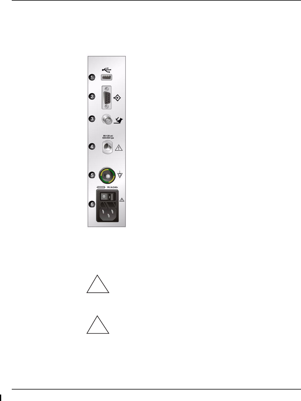
Figure 3.1 - Rear Panel Connections
Phacoemulsification Ultrasonic Handpiece
WARNING: Sterility assurance is the responsibility of the user. All non-
sterile accessories must be sterilized prior to use.
WARNING: Prior to using any invasive portions of the handpiece
assembly, examine under the microscope for any obvious damage, oxidation, or the
presence of foreign material. If any questionable characteristics are noted, use a
backup handpiece for surgery. Use of contaminated or damaged system accessories
can cause patient injury.
1. USB Port 4. Compressed Air
2. Communications Port 5. Potential Equalizer
3. Foot Pedal Connector 6. Power Switch and Power Cord Connection
!
!
3 • System Setup
WHITESTAR SIGNATURE™ System Rx Only – Z370101 Rev. 05 0807 3-15
1. Use caution to prevent burns when handling the handpiece directly from
sterilization.
2. Remove the tubing cassette and accessories from the tubing pack and place
them in the sterile area.
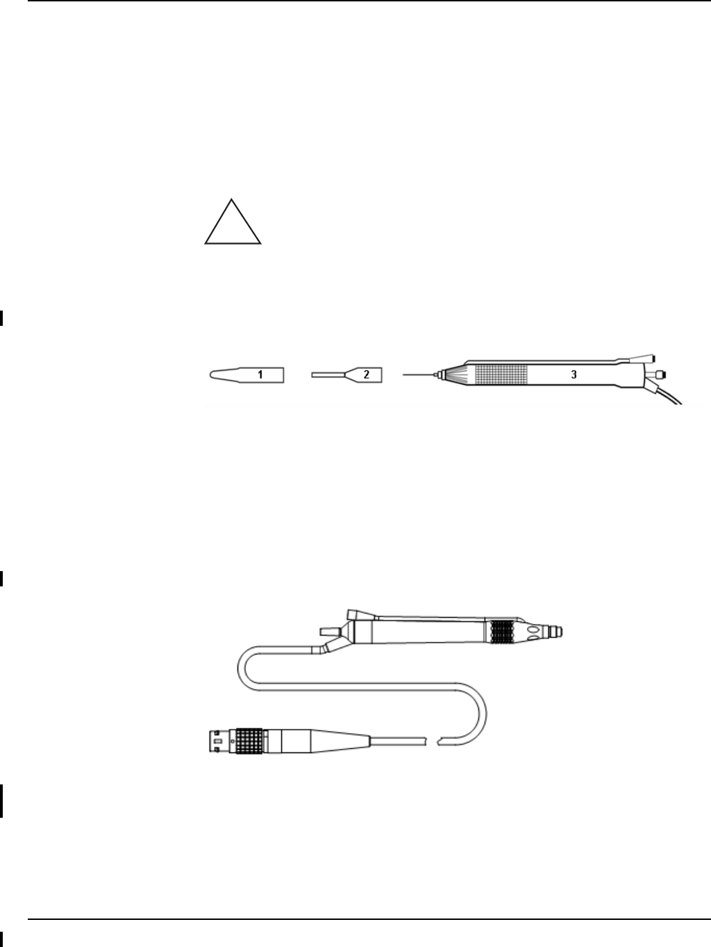
3. Assemble the phaco handpiece as shown below. You need the handpiece,
titanium phaco tip, the appropriate tip wrench, one of the infusion sleeves and
the test chamber.
CAUTION: NEVER ATTEMPT TO STRAIGHTEN A BENT
NEEDLE. THIS MIGHT PRODUCE A BROKEN TIP WHEN
ULTRASOUND IS APPLIED.
Figure 3.2 - Phaco Handpiece Assembly
4. Attach the connector end of the handpiece to the phaco receptacle on the front
of the WHITESTAR SIGNATURE™ System. Make sure there is no
moisture on the connectors prior to connecting. Moisture prevents the
handpiece from operating properly.
Figure 3.3 - Ellips™ Handpiece
Note:The Ellips™ handpiece can be used with either transversal or logitudinal
phaco settings.
Irrigation/Aspiration Handpiece
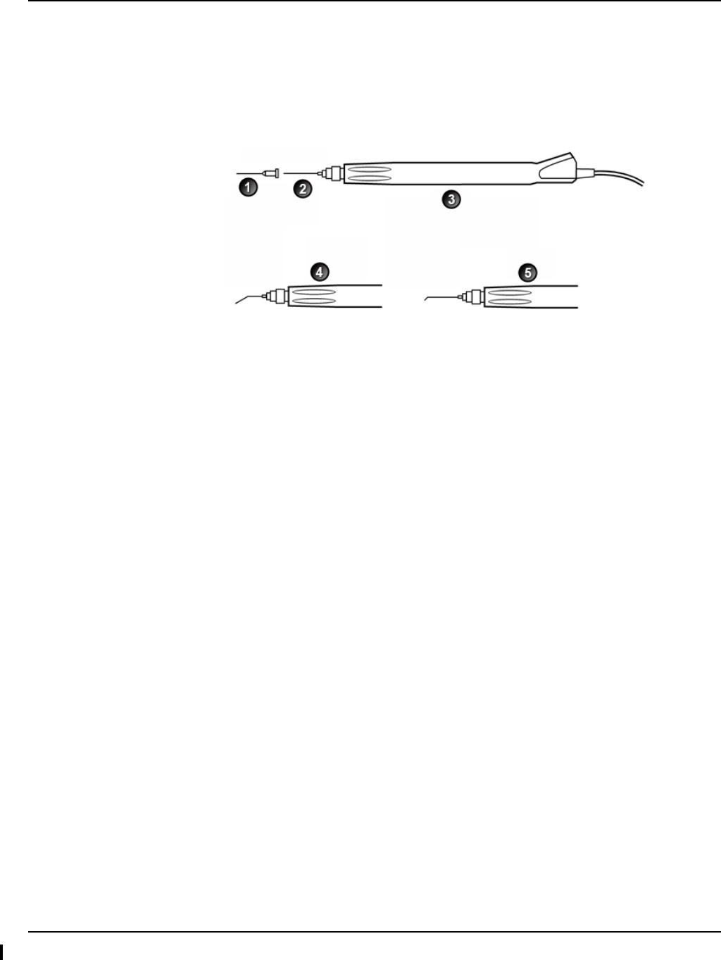
1. Assemble the SOLO™ Irrigation/Aspiration (IA) Handpiece by attaching the
infusion sleeve.
1. Test Chamber
2. Infusion Sleeve
3. Handpiece with Tip
!
3 • System Setup
WHITESTAR SIGNATURE™ System Rx Only – Z370101 Rev. 05 0807 3-16
Note: The infusion sleeve and the test chamber are provided in the
FUSION™ Tubing Pack. The LAMINAR™ Flow 20 ga. infusion
sleeves can also be used and are available with the OPOS20L or any
20 ga. LAMINAR™ Phaco Tip.
Figure 3.4 - IA Handpiece Assembly
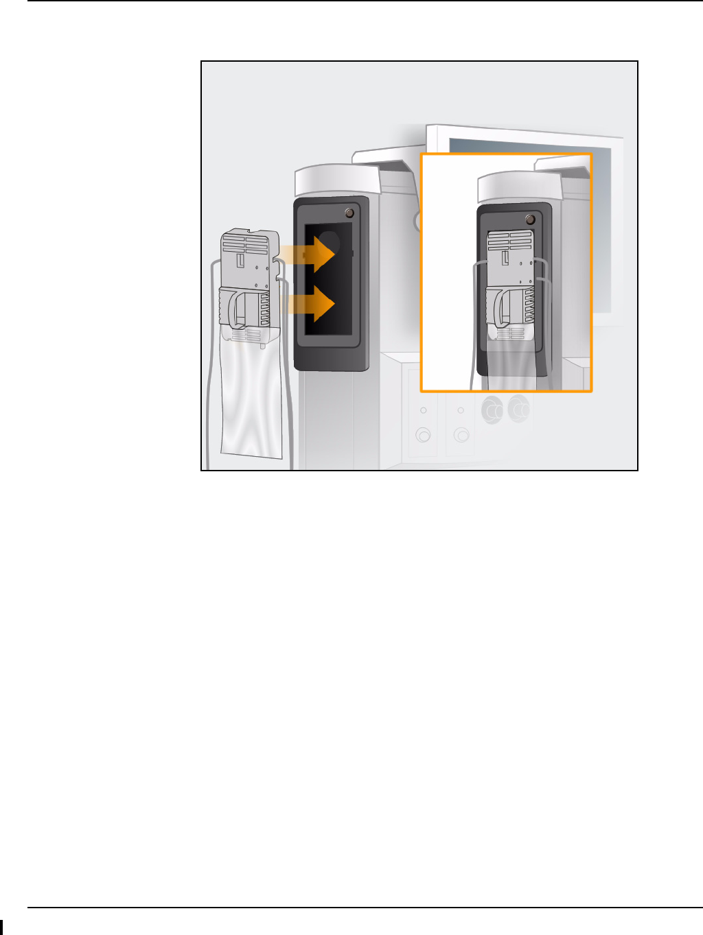
Load the FUSION™ Tubing Cassette
1. Open the tubing pack packaging.
2. Install the FUSION™ cassette into the side receptacle, as shown below.
3. Make sure that the drainage bag is properly attached to the cassette.
Note: Press the button above the cassette to remove the cassette.
1. Infusion Sleeve 4. SOLOTM Curved Tip
2. SOLOTM Straight Tip 5. SOLOTM 45o Silicone Sleeve Tip
3. Handpiece
3 • System Setup
WHITESTAR SIGNATURE™ System Rx Only – Z370101 Rev. 05 0807 3-17
Figure 3.5 - Loading the FUSION™ Tubing Cassette
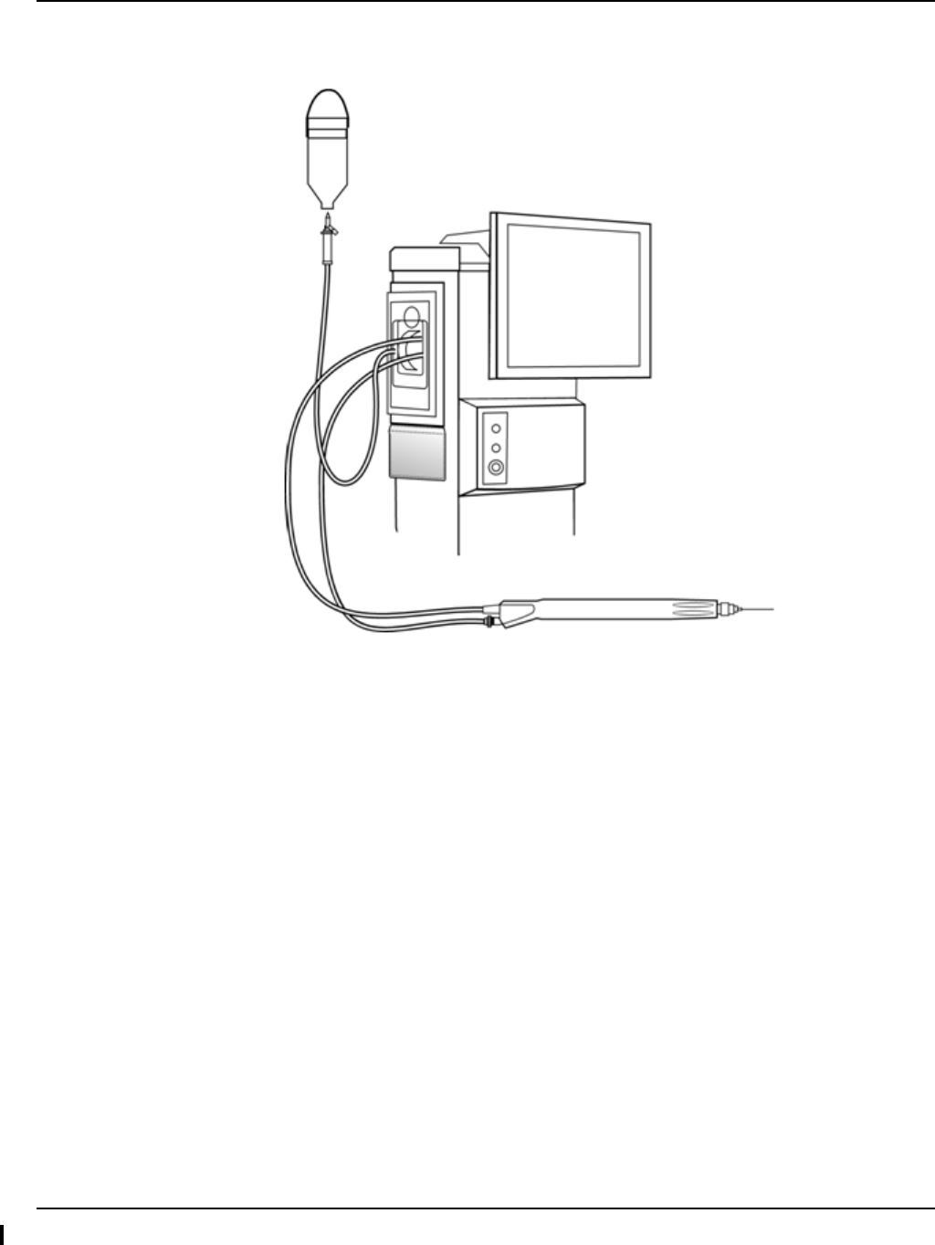
Setup Completion
IMPORTANT! Before you insert the spike into the bottle, shake the irrigation drip
chamber at the end of the irrigation tubing to confirm that the irrigation valve
moves. If the valve does not rattle, the valve cannot operate properly and irrigation
cannot flow.
1. Place a new bottle of balanced salt solution on the top of the system console.
2. Insert the drip chamber spike into the balanced salt solution bottle.
3. Hang the balanced salt solution bottle from the Programmable Power IV Pole
and squeeze the drip chamber.
4. Fill the drip chamber with fluid to the half-full level. The Programmable Power
IV Pole moves to the appropriate height automatically.
5. Raise or lower the pole as required. Use the IV pole Up and Down arrows on
upper right of the touch screen. You can also use the Up/Down switch on the
console.
3 • System Setup
WHITESTAR SIGNATURE™ System Rx Only – Z370101 Rev. 05 0807 3-18
Figure 3.6 - System Setup
6. Connect the IA tubing to the desired handpiece.
7. For attachment of the tubing to the phaco handpiece, insert the male luer end of
the irrigation tubing into the phaco handpiece.
8. Attach the female luer fitting end of the aspiration tubing to the phaco
handpiece.
Note: To protect the patient from contamination, use only:
• sterile tubing sets
• sterile irrigation fluid
• sterile handpieces
3 • System Setup
WHITESTAR SIGNATURE™ System Rx Only – Z370101 Rev. 05 0807 3-19
Figure 3.7 - Phaco Handpiece Connections
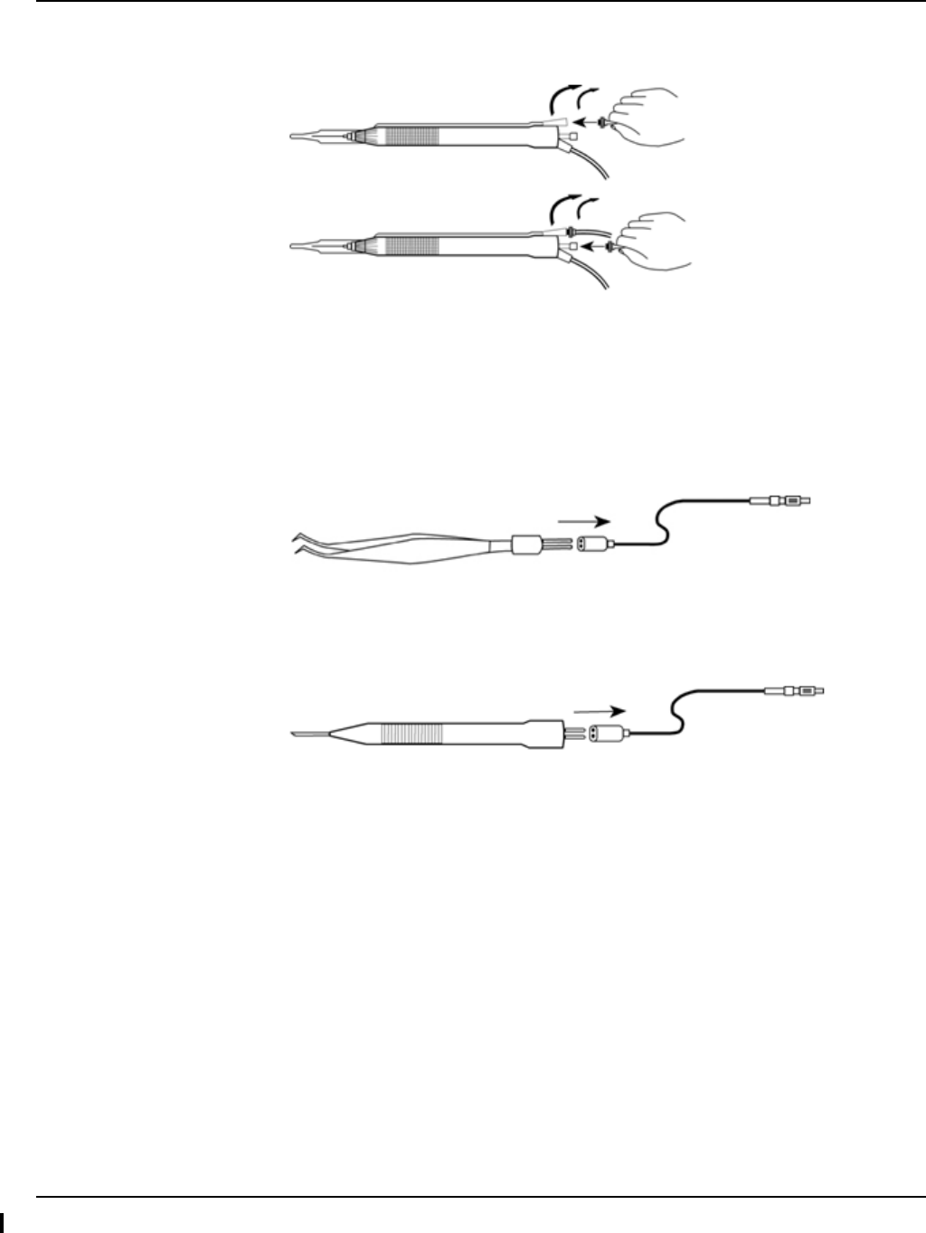
Diathermy
1. Connect the diathermy cord to the Diathermy Forceps or Pencil Probe.
2. Connect the diathermy cord to the diathermy receptacle on the console.
Figure 3.8 - Diathermy Forceps
Figure 3.9 - Diathermy Pencil
Note:Other diathermy accessories are regionally available. Contact your AMO
representative.
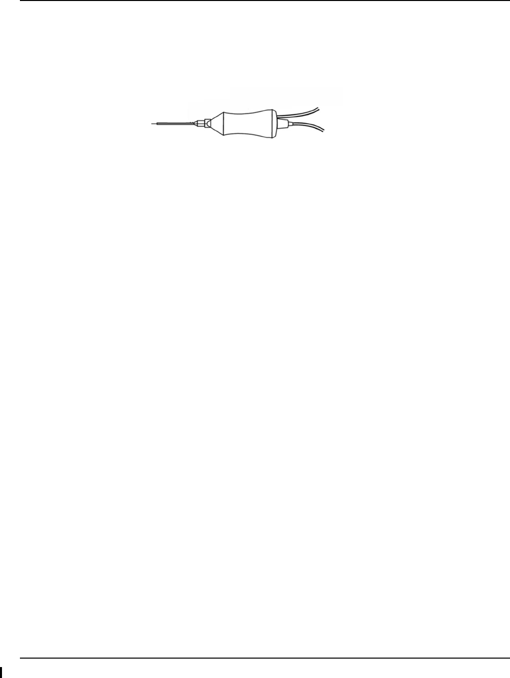
Vitrectomy
If vitrectomy is indicated during surgery:
1. Connect the AMO™ Vitrectomy Cutter as shown below. Vitrectomy requires
the following components:
• IA Tubing (from FUSION™ Tubing Cassette)
• Vitrectomy Cutter
• Vitrectomy Infusion Sleeve, or a 23 Gauge Limbal Infusion Needle, if
desired.
3 • System Setup
WHITESTAR SIGNATURE™ System Rx Only – Z370101 Rev. 05 0807 3-20
2. Assemble the handpiece using the instructions provided with the vitrectomy
cutter.
Figure 3.10 - Vitrectomy Cutter
3. Attach the connector end of the vitrectomy cord to the vitrectomy receptacle on
the console.
Pre-Operative Sterilization
The Instrument Sterilization Procedures in Chapter 9, “Care and Cleaning” identify
the WHITESTAR SIGNATURE™ System instruments that must be sterilized prior
to each surgical case. The recommended sterilization techniques, times and
temperatures are given in Chapter 9, “Care and Cleaning”. AMO recommends that
you follow the sterilization guidelines to maximize the life of your WHITESTAR
SIGNATURE™ System instruments.
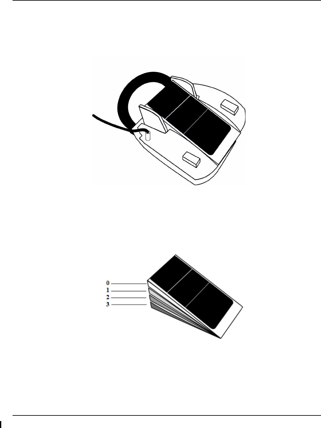
Footpedal The footpedal controls all of the WHITESTAR SIGNATURE™ System functions,
therefore, it is essential that you understand the footpedal operation.
The System software automatically detects if a footpedal is connected during power
up, and the footpedal configuration screen automatically loads to provide the
appropriate settings options.
The footpedal settings and adjustments can be selected and preset for the footpedal
in the Configuration screen. Instructions for the footpedal settings are given in
Chapter 5, “Anterior Segment Surgery Operating Modes”. The footpedal housing
incorporates a handle, making the footpedal easy to grip for repositioning and
storage.
3 • System Setup
WHITESTAR SIGNATURE™ System Rx Only – Z370101 Rev. 05 0807 3-21
The Footpedal cable attaches to the footpedal connector on the rear of the console.
Note: You must NEVER handle the footpedal by the cable.
Figure 3.11 - Footpedal
Footpedal Operation
The footpedal has three active “PITCH” ranges, which are referred to as Positions
1, 2 and 3. Position 0 is the Off position, and Position 3 is the fully pressed position.
The ranges are shown below.
Figure 3.12 - Footpedal “Pitch” Positions
The footpedal position determines the function that is delivered by the handpiece,
which depends on the mode selected on the touch screen. When the footpedal has
been connected, place your foot on the pedal and press to the desired position. The
footpedal settings and programming are addressed in Chapter 5, “Anterior Segment
Surgery Operating Modes”.

3 • System Setup
WHITESTAR SIGNATURE™ System Rx Only – Z370101 Rev. 05 0807 3-22
Reflux
Reflux is the reversal of aspirated fluid flow to assist in the release of unwanted
material. The reflux pinch valve opens the aspiration tubing to the positive bottle
head pressure (dependent on IV pole height and gravity) and causes fluid to flow
toward the handpiece. Reflux stays on until the reflux pinch valve is closed. Reflux
must not be used to clear clogged handpieces but reflux can be used to identify a
blockage. The Reflux action can be programmed on any available footpedal switch.
WARNING: Reflux is a user selectable switch option. In the event of
captured tissue and vacuum present, deactivation of reflux requires the user to
release the footpedal to position 1 to open the vent valve.
Programmable
Power IV Pole
The Programmable Power IV Pole is controlled by the Up and Down arrows on the
upper right of the touch screen, next to the bottle height indicator. These controls
are used to raise and lower the pole, and the height is indicated in the
Programmable Power IV Pole screen. The Programmable Power IV Pole moves at
a rate of approximately 6 cm (2 inches) per second.
The Programmable Power IV Pole is adjustable from 0 to 107 centimeters, and can
be set for either inches or centimeters. The height measurement is relative to the
distance from the irrigation valve to the center of the drip chamber. The
Programmable Power IV Pole height for each fluidic mode or submode (PHACO,
IA, VIT) is saved in the WHITESTAR SIGNATURE™ System memory. A
Maximum IV Pole height can be set on the Diagnostics screen.
When a surgery mode is selected, the Programmable Power IV Pole automatically
moves to the preset height. To manually adjust the IV pole height, use the Up and
Down arrows on the touch screen. Manual adjustments to the IV pole can also be
made by pressing the rocker switch located on the side of the console. If a
maximum height has been set, the IV pole will not move above that height.
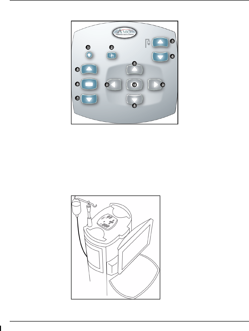
Wireless Remote
Control (Optional)
The wireless remote control keypad can be used to operate the WHITESTAR
SIGNATURE™ System. All Modes, Programs, Diagnostics and End Case can be
accessed and adjustments to the settings can be made with the remote. The buttons
on the remote keypad work the same as the controls on the WHITESTAR
SIGNATURE™ System touch screen.
!
3 • System Setup
WHITESTAR SIGNATURE™ System Rx Only – Z370101 Rev. 05 0807 3-23
Figure 3.13 - Wireless Remote Control Module
When not in use, store the Wireless Remote Control on the top of the system to
charge the battery.
Figure 3.14 - Wireless Remote Control Module Storage
1. Remote Backlight On 6. Mode Select
2. Reload 7. Mode Down
3. IV Pole Up 8. Navigation Up/Down
4. IV Pole Down 9. Navigation Left/Right
5. Mode Up 10. Select
3 • System Setup
WHITESTAR SIGNATURE™ System Rx Only – Z370101 Rev. 05 0807 3-24
Surgical Media
Center (SMC)
(Optional)
The Surgical Media Center (SMC) is used to record the surgery and the instrument
settings to be viewed at a later date and time. The surgery is displayed on a monitor
with the instrument settings. The SMC hardware is connected to your
WHITESTAR SIGNATURE™ System Communications port on the rear panel.
(See Figure 3.1 Rear Panel Connections.)
1. To configure the Surgical Media Center, select:
• Configuration
• System Configuration
•SMC
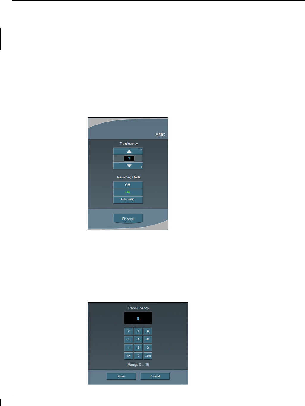
Figure 3.15 - Surgical Media Center Pop-up Window
2. Use the Up and Down arrows to adjust the settings. Translucency is used to
make the overlay (instrument settings) more or less opaque.
Note: Press on the number in the control panel to open a numeric keypad and
enter the required value. Press Enter on the Keypad pop-up window
when you are finished.
Figure 3.16 - Numeric Keypad Pop-up Window

3 • System Setup
WHITESTAR SIGNATURE™ System Rx Only – Z370101 Rev. 05 0807 3-25
3. Select the Recording Mode. Off, On, or Automatic. If the Recording Mode
is On, the recording continues between cases. Automatic stops recording
between cases.
Note: The Footpedal Switch can be set up to activate the SMC Record function.
4. Press Finished to close the pop-up window.
Shutdown Sequence
– Anterior Segment
Surgery
The following is a general overview of the steps to be taken to shut the System
down after surgery:
1. Select End Case.
2. Select Shutdown. At the prompt, select Yes.
3. Turn the system Off at the back of the console.
4. Remove the power cord from the power outlet.
5. Wrap the excess power cord neatly around the cord wrap on the back of the
console.
6. Place the footpedal in the storage area on the console.
7. Place the Wireless Remote Control on top of the console to charge.
8. Refer to Chapter 9, “Care and Cleaning”, Cleaning Procedures for additional
information.