Johnson and Johnson Surgical Vision SIGREMS3 Signature Pro Remote Control, BT2.0 User Manual signature users manual
Abbott Medical Optics Signature Pro Remote Control, BT2.0 signature users manual
User Manual

OPERATOR’S
MANUAL
Trademarks AMO, WHITESTAR, ELLIPS, the ELLIPS logo, FUSION, the
FUSION logo, LAMINAR, PHACOFIT, CATALYS, and
WHITESTAR SIGNATURE are trademarks owned by or licensed to
Abbott Laboratories, its subsidiaries or affiliates.
DUET and SOLO are trademarks of Micro-Surgical Technology, Inc.
BLUETOOTH is a trademark of Bluetooth SIG, Inc.
All other brand names, products, and company names mentioned in
this document are the trade name, service mark, or trademarks of their
respective owners.
Compliance In accordance with IEC/EN
60601-1
Abbott Medical Optics Inc.
1700 E. St. Andrew Place
Santa Ana, CA, USA 92705
1-877-AMO-4-LIFE (USA)
www.abbottmedicaloptics.com
Product of USA
AMO Ireland
Block B
Liffey Valley Office Campus
Quarryvale, Co. Dublin, Ireland
Order Surgical
Products IOLs and Phaco Supplies
Call 1-877-AMO-4-LIFE (USA)
For outside the United States: 1-800-511-0911.
Returns or Technical
Service Call 1-877-AMO-4-LIFE (USA)
All returns must be accompanied by a RGA#
(Returned Goods Authorization)
For outside the United States: 1-800-511-0911.
Rx Only
© 2015 Abbott Medical Optics Inc.
RX Only – NGP Z370500 Rev. B 1116

RX Only – NGP Z370500 Rev. B 1116
3
TABLE OF CONTENTS
Introduction . . . . . . . . . . . . . . . . . . . . . . . . . . . . . . . . . . . . . . . . . . . . . . . . . . . . . . . . . . . . 1-1
About this Manual . . . . . . . . . . . . . . . . . . . . . . . . . . . . . . . . . . . . . . . . . . . . . . . . . . . . . . . . 1-2
About
Phacoemulsification
. . . . . . . . . . . . . . . . . . . . . . . . . . . . . . . . . . . . . . . . . . . . . . . . . . 1-2
Intended Use . . . . . . . . . . . . . . . . . . . . . . . . . . . . . . . . . . . . . . . . . . . . . . . . . . . . . . . . . . . . . 1-2
WHITESTAR SIGNATURE PRO System Description and
Features
. . . . . . . . . . . . . . . . . 1-2
WHITESTAR
Technology
. . . . . . . . . . . . . . . . . . . . . . . . . . . . . . . . . . . . . . . . . . . . . . . . . . 1-2
FUSION Fluidics System . . . . . . . . . . . . . . . . . . . . . . . . . . . . . . . . . . . . . . . . . . . . . . . . . . . 1-3
Accessories . . . . . . . . . . . . . . . . . . . . . . . . . . . . . . . . . . . . . . . . . . . . . . . . . . . . . . . . . . . . . . 1-4
WHITESTAR SIGNATURE PRO System Console . . . . . . . . . . . . . . . . . . . . . . . . . . . . . . 1-5
WHITESTAR SIGNATURE PRO System Operating Modes . . . . . . . . . . . . . . . . . . . . . . . 1-6
Safety Precautions. . . . . . . . . . . . . . . . . . . . . . . . . . . . . . . . . . . . . . . . . . . . . . . . . . . . . . . . . 1-8
Warnings
. . . . . . . . . . . . . . . . . . . . . . . . . . . . . . . . . . . . . . . . . . . . . . . . . . . . . . . . . . . . . . . 1-11
Symbol
Definitions
. . . . . . . . . . . . . . . . . . . . . . . . . . . . . . . . . . . . . . . . . . . . . . . . . . . . . . . 1-15
System Disposal . . . . . . . . . . . . . . . . . . . . . . . . . . . . . . . . . . . . . . . . . . . . . . . . . . . . . . . . . 1-22
System
Components
. . . . . . . . . . . . . . . . . . . . . . . . . . . . . . . . . . . . . . . . . . . . . . . . . . . . . . 2-1
Receipt and Inspection Instructions . . . . . . . . . . . . . . . . . . . . . . . . . . . . . . . . . . . . . . . . . . . 2-2
WHITESTAR SIGNATURE PRO System
Components
. . . . . . . . . . . . . . . . . . . . . . . . . . . 2-2
Surgery Start Up . . . . . . . . . . . . . . . . . . . . . . . . . . . . . . . . . . . . . . . . . . . . . . . . . . . . . . . . 3-1
WHITESTAR SIGNATURE PRO System Setup . . . . . . . . . . . . . . . . . . . . . . . . . . . . . . . . 3-2
Front and Rear Panel Connections . . . . . . . . . . . . . . . . . . . . . . . . . . . . . . . . . . . . . . . . . . . . 3-2
IV Pole Setup . . . . . . . . . . . . . . . . . . . . . . . . . . . . . . . . . . . . . . . . . . . . . . . . . . . . . . . . . . . . 3-3
Handpiece Setup . . . . . . . . . . . . . . . . . . . . . . . . . . . . . . . . . . . . . . . . . . . . . . . . . . . . . . . . . . 3-4
Startup
. . . . . . . . . . . . . . . . . . . . . . . . . . . . . . . . . . . . . . . . . . . . . . . . . . . . . . . . . . . . . . . . . . 3-8
Install the FUSION Pack . . . . . . . . . . . . . . . . . . . . . . . . . . . . . . . . . . . . . . . . . . . . . . . . . . . 3-9
Cup Fill . . . . . . . . . . . . . . . . . . . . . . . . . . . . . . . . . . . . . . . . . . . . . . . . . . . . . . . . . . . . . . . . 3-10
Prime/Tune . . . . . . . . . . . . . . . . . . . . . . . . . . . . . . . . . . . . . . . . . . . . . . . . . . . . . . . . . . . . . 3-11
Verify Irrigation/Aspiration Balance . . . . . . . . . . . . . . . . . . . . . . . . . . . . . . . . . . . . . . . . . 3-14
Priming for Vitrectomy. . . . . . . . . . . . . . . . . . . . . . . . . . . . . . . . . . . . . . . . . . . . . . . . . . . . 3-15
Selecting and Changing Mode
Parameters
. . . . . . . . . . . . . . . . . . . . . . . . . . . . . . . . . . . . . 3-16
System
Check-out
. . . . . . . . . . . . . . . . . . . . . . . . . . . . . . . . . . . . . . . . . . . . . . . . . . . . . . . . 3-17
Pre-operative Sterilization . . . . . . . . . . . . . . . . . . . . . . . . . . . . . . . . . . . . . . . . . . . . . . . . . 3-20
System Shutdown . . . . . . . . . . . . . . . . . . . . . . . . . . . . . . . . . . . . . . . . . . . . . . . . . . . . . . . . 3-20
End Case . . . . . . . . . . . . . . . . . . . . . . . . . . . . . . . . . . . . . . . . . . . . . . . . . . . . . . . . . . . . . . . 3-21

RX Only – NGP Z370500 Rev. B 1116
4
WHITESTAR SIGNATURE PRO System
Table of Contents
Surgeon Settings . . . . . . . . . . . . . . . . . . . . . . . . . . . . . . . . . . . . . . . . . . . . . . . . . . . . . . . . . 4-1
Select Surgeon . . . . . . . . . . . . . . . . . . . . . . . . . . . . . . . . . . . . . . . . . . . . . . . . . . . . . . . . . . . 4-2
Add a New Surgeon . . . . . . . . . . . . . . . . . . . . . . . . . . . . . . . . . . . . . . . . . . . . . . . . . . . . . . . 4-3
Delete Surgeon . . . . . . . . . . . . . . . . . . . . . . . . . . . . . . . . . . . . . . . . . . . . . . . . . . . . . . . . . . . 4-3
Edit a Surgeon. . . . . . . . . . . . . . . . . . . . . . . . . . . . . . . . . . . . . . . . . . . . . . . . . . . . . . . . . . . . 4-4
Foot Pedal
Setup
. . . . . . . . . . . . . . . . . . . . . . . . . . . . . . . . . . . . . . . . . . . . . . . . . . . . . . . . . . 4-6
Set Sound Levels . . . . . . . . . . . . . . . . . . . . . . . . . . . . . . . . . . . . . . . . . . . . . . . . . . . . . . . . 4-33
Surgeon – Assign Order . . . . . . . . . . . . . . . . . . . . . . . . . . . . . . . . . . . . . . . . . . . . . . . . . . . 4-35
Program Settings . . . . . . . . . . . . . . . . . . . . . . . . . . . . . . . . . . . . . . . . . . . . . . . . . . . . . . . . 5-1
Create a New Program . . . . . . . . . . . . . . . . . . . . . . . . . . . . . . . . . . . . . . . . . . . . . . . . . . . . . 5-2
Delete a Program . . . . . . . . . . . . . . . . . . . . . . . . . . . . . . . . . . . . . . . . . . . . . . . . . . . . . . . . . 5-2
Edit a Program Name . . . . . . . . . . . . . . . . . . . . . . . . . . . . . . . . . . . . . . . . . . . . . . . . . . . . . . 5-3
Program
Settings
. . . . . . . . . . . . . . . . . . . . . . . . . . . . . . . . . . . . . . . . . . . . . . . . . . . . . . . . . . 5-3
Default Settings . . . . . . . . . . . . . . . . . . . . . . . . . . . . . . . . . . . . . . . . . . . . . . . . . . . . . . . . . . 5-8
Phaco Power Settings . . . . . . . . . . . . . . . . . . . . . . . . . . . . . . . . . . . . . . . . . . . . . . . . . . . . . 5-13
WHITESTAR
Technology
. . . . . . . . . . . . . . . . . . . . . . . . . . . . . . . . . . . . . . . . . . . . . . . . . 5-15
FUSION Fluidics Phaco . . . . . . . . . . . . . . . . . . . . . . . . . . . . . . . . . . . . . . . . . . . . . . . . . . . 5-20
Lock a Program. . . . . . . . . . . . . . . . . . . . . . . . . . . . . . . . . . . . . . . . . . . . . . . . . . . . . . . . . . 5-28
Copy a Surgeon Program . . . . . . . . . . . . . . . . . . . . . . . . . . . . . . . . . . . . . . . . . . . . . . . . . . 5-29
Program – Assign Order . . . . . . . . . . . . . . . . . . . . . . . . . . . . . . . . . . . . . . . . . . . . . . . . . . . 5-29
System Configuration. . . . . . . . . . . . . . . . . . . . . . . . . . . . . . . . . . . . . . . . . . . . . . . . . . . . . 6-1
Setting the Maximum IV Pole Height . . . . . . . . . . . . . . . . . . . . . . . . . . . . . . . . . . . . . . . . . 6-2
Testing the IV Pole . . . . . . . . . . . . . . . . . . . . . . . . . . . . . . . . . . . . . . . . . . . . . . . . . . . . . . . . 6-3
Event Log . . . . . . . . . . . . . . . . . . . . . . . . . . . . . . . . . . . . . . . . . . . . . . . . . . . . . . . . . . . . . . . 6-4
Wireless Setup - Foot Pedal and Remote Control . . . . . . . . . . . . . . . . . . . . . . . . . . . . . . . . 6-5
Wireless Remote
Test
. . . . . . . . . . . . . . . . . . . . . . . . . . . . . . . . . . . . . . . . . . . . . . . . . . . . . 6-10
Touch Screen Calibration . . . . . . . . . . . . . . . . . . . . . . . . . . . . . . . . . . . . . . . . . . . . . . . . . . 6-11
View Software Versions . . . . . . . . . . . . . . . . . . . . . . . . . . . . . . . . . . . . . . . . . . . . . . . . . . . 6-12
System Self Test . . . . . . . . . . . . . . . . . . . . . . . . . . . . . . . . . . . . . . . . . . . . . . . . . . . . . . . . . 6-13
Language
Selection
. . . . . . . . . . . . . . . . . . . . . . . . . . . . . . . . . . . . . . . . . . . . . . . . . . . . . . . 6-14
Surgical Media Center (SMC) (Optional) . . . . . . . . . . . . . . . . . . . . . . . . . . . . . . . . . . . . . 6-15
Set the System Date and Time . . . . . . . . . . . . . . . . . . . . . . . . . . . . . . . . . . . . . . . . . . . . . . 6-16
Set Units of Measure for Vacuum . . . . . . . . . . . . . . . . . . . . . . . . . . . . . . . . . . . . . . . . . . . 6-17
Service
Interval
. . . . . . . . . . . . . . . . . . . . . . . . . . . . . . . . . . . . . . . . . . . . . . . . . . . . . . . . . . 6-18
Import/Export Database . . . . . . . . . . . . . . . . . . . . . . . . . . . . . . . . . . . . . . . . . . . . . . . . . . . 6-19
Backup All . . . . . . . . . . . . . . . . . . . . . . . . . . . . . . . . . . . . . . . . . . . . . . . . . . . . . . . . . . . . . 6-21
Print to File . . . . . . . . . . . . . . . . . . . . . . . . . . . . . . . . . . . . . . . . . . . . . . . . . . . . . . . . . . . . . 6-22
Restore Database. . . . . . . . . . . . . . . . . . . . . . . . . . . . . . . . . . . . . . . . . . . . . . . . . . . . . . . . . 6-23
Restore All . . . . . . . . . . . . . . . . . . . . . . . . . . . . . . . . . . . . . . . . . . . . . . . . . . . . . . . . . . . . . 6-24
Delete a Backup Database . . . . . . . . . . . . . . . . . . . . . . . . . . . . . . . . . . . . . . . . . . . . . . . . . 6-25

RX Only – NGP Z370500 Rev. B 1116
5
WHITESTAR SIGNATURE PRO System
Table of Contents
Care and Cleaning . . . . . . . . . . . . . . . . . . . . . . . . . . . . . . . . . . . . . . . . . . . . . . . . . . . . . . . 7-1
Cleaning and Sterilization Procedures . . . . . . . . . . . . . . . . . . . . . . . . . . . . . . . . . . . . . . . . . 7-2
Phaco Handpiece. . . . . . . . . . . . . . . . . . . . . . . . . . . . . . . . . . . . . . . . . . . . . . . . . . . . . . . . . . 7-2
Irrigation/Aspiration Handpiece . . . . . . . . . . . . . . . . . . . . . . . . . . . . . . . . . . . . . . . . . . . . . . 7-2
Diathermy
Handpiece
. . . . . . . . . . . . . . . . . . . . . . . . . . . . . . . . . . . . . . . . . . . . . . . . . . . . . . 7-2
Vitrectomy Cutter . . . . . . . . . . . . . . . . . . . . . . . . . . . . . . . . . . . . . . . . . . . . . . . . . . . . . . . . . 7-2
Touch Screen
Cleaning
. . . . . . . . . . . . . . . . . . . . . . . . . . . . . . . . . . . . . . . . . . . . . . . . . . . . . 7-2
Error Messages Troubleshooting and Diagnostics . . . . . . . . . . . . . . . . . . . . . . . . . . . . . 8-1
Most Common User-Correctable Problems . . . . . . . . . . . . . . . . . . . . . . . . . . . . . . . . . . . . . 8-2
Fuse Replacement Procedure . . . . . . . . . . . . . . . . . . . . . . . . . . . . . . . . . . . . . . . . . . . . . . . . 8-2
Advanced Linear Pedal Battery Replacement . . . . . . . . . . . . . . . . . . . . . . . . . . . . . . . . . . . 8-4
Charging Options for Wireless Devices . . . . . . . . . . . . . . . . . . . . . . . . . . . . . . . . . . . . . . . . 8-5
Troubleshooting . . . . . . . . . . . . . . . . . . . . . . . . . . . . . . . . . . . . . . . . . . . . . . . . . . . . . . . . . . 8-7
General . . . . . . . . . . . . . . . . . . . . . . . . . . . . . . . . . . . . . . . . . . . . . . . . . . . . . . . . . . . . . . . . . 8-7
Irrigation . . . . . . . . . . . . . . . . . . . . . . . . . . . . . . . . . . . . . . . . . . . . . . . . . . . . . . . . . . . . . . . . 8-9
Aspiration . . . . . . . . . . . . . . . . . . . . . . . . . . . . . . . . . . . . . . . . . . . . . . . . . . . . . . . . . . . . . . 8-10
Phacoemulsification . . . . . . . . . . . . . . . . . . . . . . . . . . . . . . . . . . . . . . . . . . . . . . . . . . . . . . 8-12
Diathermy . . . . . . . . . . . . . . . . . . . . . . . . . . . . . . . . . . . . . . . . . . . . . . . . . . . . . . . . . . . . . . 8-13
Vitrectomy . . . . . . . . . . . . . . . . . . . . . . . . . . . . . . . . . . . . . . . . . . . . . . . . . . . . . . . . . . . . . 8-13
Status, Warning and Error Messages . . . . . . . . . . . . . . . . . . . . . . . . . . . . . . . . . . . . . . . . . 8-14
Error Messages . . . . . . . . . . . . . . . . . . . . . . . . . . . . . . . . . . . . . . . . . . . . . . . . . . . . . . . . . . 8-14
Warranty and Maintenance . . . . . . . . . . . . . . . . . . . . . . . . . . . . . . . . . . . . . . . . . . . . . . . 9-1
Warranty Statement . . . . . . . . . . . . . . . . . . . . . . . . . . . . . . . . . . . . . . . . . . . . . . . . . . . . . . . 9-2
Specifications . . . . . . . . . . . . . . . . . . . . . . . . . . . . . . . . . . . . . . . . . . . . . . . . . . . . . . . . . . 10-1
Physical
Specifications
. . . . . . . . . . . . . . . . . . . . . . . . . . . . . . . . . . . . . . . . . . . . . . . . . . . . 10-2
Environmental
Specifications
. . . . . . . . . . . . . . . . . . . . . . . . . . . . . . . . . . . . . . . . . . . . . . . 10-3
Electrical Specifications . . . . . . . . . . . . . . . . . . . . . . . . . . . . . . . . . . . . . . . . . . . . . . . . . . . 10-3
Phacoemulsification Specifications . . . . . . . . . . . . . . . . . . . . . . . . . . . . . . . . . . . . . . . . . . 10-3
Irrigation and Aspiration
Specifications
. . . . . . . . . . . . . . . . . . . . . . . . . . . . . . . . . . . . . . . 10-4
Vitrectomy Specifications. . . . . . . . . . . . . . . . . . . . . . . . . . . . . . . . . . . . . . . . . . . . . . . . . . 10-4
Diathermy Specifications . . . . . . . . . . . . . . . . . . . . . . . . . . . . . . . . . . . . . . . . . . . . . . . . . . 10-5
Diathermy Power Graphs . . . . . . . . . . . . . . . . . . . . . . . . . . . . . . . . . . . . . . . . . . . . . . . . . . 10-6
Diathermy Power versus Load
Impedance
. . . . . . . . . . . . . . . . . . . . . . . . . . . . . . . . . . . . . 10-9
Phaco Power Graphs . . . . . . . . . . . . . . . . . . . . . . . . . . . . . . . . . . . . . . . . . . . . . . . . . . . . . 10-10
Phaco Tip Velocity . . . . . . . . . . . . . . . . . . . . . . . . . . . . . . . . . . . . . . . . . . . . . . . . . . . . . . 10-11
Bottle Height Pressure . . . . . . . . . . . . . . . . . . . . . . . . . . . . . . . . . . . . . . . . . . . . . . . . . . . 10-11
Accessories and Parts Reordering . . . . . . . . . . . . . . . . . . . . . . . . . . . . . . . . . . . . . . . . . 11-1
List of Accessories with Part Numbers. . . . . . . . . . . . . . . . . . . . . . . . . . . . . . . . . . . . . . . . 11-2
Index . . . . . . . . . . . . . . . . . . . . . . . . . . . . . . . . . . . . . . . . . . . . . . . . . . . . . . . . . . . . . . . . . 12-1

RX Only – NGP Z370500 Rev. B 1116
1-1
1 INTRODUCTION
About this Manual
About Phacoemulsification
Intended Use
WHITESTAR SIGNATURE PRO System Description and Features
WHITESTAR Technology
FUSION Fluidics System
Accessories
WHITESTAR SIGNATURE PRO System Console
WHITESTAR SIGNATURE PRO System Operating Modes
Safety Precautions
Warnings
Symbol Definitions
System Disposal

RX Only – NGP Z370500 Rev. B 1116
1-2
WHITESTAR SIGNATURE PRO System
1 • Introduction
About this Manual This manual includes information about the design of the WHITESTAR
SIGNATURE PRO System for anterior segment (phacoemulsification) surgical
procedures.
This manual includes information about optional system enhancements. Your
Abbott Medical Optics Inc. (AMO) representative can confirm the availability of
these features for your system configuration and availability in your area.
About
Phacoemulsification Over thirty years ago, Dr. Charles Kelman conceived and developed
phacoemulsification (phaco), a method of cataract removal by use of ultrasonic
emulsification with aspiration of the cataractous lens through a small incision.
Phacoemulsification is advantageous for both patient and surgeon:
• Greater intraoperative control.
• The smaller incision requires fewer or no sutures, poses less risk of infection and
induced astigmatism, and gives better long-term and short-term predictability of
vision.
• Patients are able to resume normal activity much sooner and with fewer
restrictions than with traditional cataract extraction surgeries.
AMO supports phacoemulsification with sophisticated instrumentation that
optimizes the benefits of this surgical procedure.
Intended Use The WHITESTAR SIGNATURE PRO System is a modular ophthalmic
microsurgical system that facilitates anterior segment (cataract) surgery. The
modular design allows the users to configure the system to meet their surgical
requirements.
WHITESTAR
SIGNATURE PRO
System Description
and Features
The WHITESTAR SIGNATURE PRO System is a multi-functional tool for use
in anterior segment surgery procedures. The WHITESTAR SIGNATURE PRO
System represents the latest generation of AMO phacoemulsification technology.
Designed and manufactured into every WHITESTAR SIGNATURE
PRO
System
are safety, ease-of-use, and reliability. The WHITESTAR SIGNATURE
PRO System meets applicable United States and International safety requirements
for this type of device.
The WHITESTAR SIGNATURE PRO System contains a number of features
based on extensive research and clinical trials with highly trained and noted
ophthalmologists with experience as phacoemulsification surgeons.
WHITESTAR
Technology The WHITESTAR Technology represents the many enhancements to the power
modulation for the WHITESTAR SIGNATURE PRO System. The
WHITESTAR Technology enhancement was the first to deliver finely modulated
pulses of energy, interrupted by extremely brief cooling periods. This allows the
system to achieve full ultrasound cutting efficiency and magnetic followability,
while introducing less energy into the eye. Minimized ultrasonic time reduces the
risk of thermal damage.

RX Only – NGP Z370500 Rev. B 1116
1-3
WHITESTAR SIGNATURE PRO System
1 • Introduction
WHITESTAR ICE Technology
The WHITESTAR ICE Technology was the next advance in micropulse
phacoemulsification technology. This technology combined modulated ultrasonic
power (pulse shaping) with vacuum control through the use of the Chamber
Stabilization Environment (CASE).
This pulse shaping technology modified the standard “square” wave pulse, by
increasing the amplitude of the first millisecond of the on time “kick”. The
technology then set the remaining part of the on time to the standard power setting.
This process repeats for each on time pulse. This results in increased control and
efficiency in phacoemulsification.
Occlusion Mode Phaco
The Occlusion mode phaco regulates the vacuum rise time following an occlusion
of the phaco tip, without limiting the choice of aspiration rate through an
unoccluded needle. To independently control the aspiration rate and the vacuum
rise time, you can have a different aspiration rate when the needle occludes than
when the needle is unoccluded.
The Occlusion mode phaco also regulates the ultrasound power modulation. You
can program the power modulation of the phaco handpiece (continuous, pulse,
burst) to automatically change when the phaco tip changes from an unoccluded
condition to an occluded condition.
The FUSION mode allows the user to access the settings and variables for both
CASE and Occlusion mode phaco. The CASE and Occlusion mode phaco can work
together or independently.
FUSION Fluidics
System The system has both a flow-based peristaltic pump system and a vacuum-based
Venturi pump system. The patented microprocessor-based system continuously
monitors and controls intraocular conditions of the flow and vacuum in the eye.
Chamber Stabilization Environment (CASE)
CASE is an intelligent vacuum monitoring system that regulates the maximum
allowable vacuum used following the occlusion of the phaco tip. When the phaco
tip becomes occluded, the vacuum rises. Clearing of the occlusion while the
vacuum is at a high-level can lead to a post occlusion surge. When CASE is on, the
system monitors the actual vacuum levels. When the vacuum exceeds a specific
threshold for a specified duration, the system automatically adjusts the maximum
allowable vacuum setting to a lower predefined CASE maximum vacuum level.
When the occlusion clears, the system automatically restores the settings to the
original programmed maximum vacuum setting. This function makes it possible to
have a different maximum vacuum setting when the needle occludes than when the
needle is unoccluded.

RX Only – NGP Z370500 Rev. B 1116
1-4
WHITESTAR SIGNATURE PRO System
1 • Introduction
Accessories WHITESTAR Handpiece
The design of the phaco handpiece has a straight-through aspiration channel for
more efficient removal of nuclear fragments, to minimize clogging and to facilitate
cleaning. The handpiece is lightweight, slim, and well-balanced, making it
comfortable to use and easy to control.
ELLIPS FX Handpiece
The ELLIPS FX phaco handpiece is available for use with the WHITESTAR
SIGNATURE PRO System. The ELLIPS FX handpiece provides both
longitudinal and transversal movement. You can use the handpiece with a straight
tip or a curved tip.
Foot Pedal
The foot pedal controls the various operating modes of the instrument. You can
program the foot pedal settings through the user interface. You can use either the
Single Linear foot pedal, the Advanced Control Pedal or the Advanced Linear
Pedal with the system.
The foot pedal design offers control through the use of increased linearity with the
foot pedal movement. The design provides uniform pressure throughout the foot
pedal movement, easing foot and leg fatigue. You can select the degrees of
movement for each foot pedal position. You can save the settings for each surgeon/
mode, pitch for the standard foot pedal and the Advanced Linear Pedal and pitch
and yaw for the Advanced Control Pedal giving the pedal dual linear functionality.
Programmable switches can activate reflux, giving an immediate response.
Wireless Remote Control
The surgery can be controlled from the wireless remote control keypad. You can
access all surgical modes and adjust all surgical settings with the use of the wireless
remote control. Back-lighting supports low light operating room conditions.

RX Only – NGP Z370500 Rev. B 1116
1-5
WHITESTAR SIGNATURE PRO System
1 • Introduction
WHITESTAR
SIGNATURE PRO
System Console
Operating room teams contributed significantly to the successful design of the
system console. The solid wheel base and locking wheels make the console stable
and smooth rolling. An adjustable height Mayo tray accommodates the handpieces
and tubing. The remote control is wireless and recharges when attached to the AC
Charging Adapter. The foot pedal has an open bin area for storage.
WHITESTAR SIGNATURE PRO System Display (Graphic User
Interface-GUI)
The system graphic screen display is easy to read and easy to operate. You can see
at a glance the status of the system. The screen gives you visual indication of
operating modes, settings, and system status. Messages cue you through the
procedure, and error messages indicate improper connections, or selections. Help
information is available when resolving error messages.
Prime/Tune
Before the start of each surgical case, the system requires that you run prime, tune
or prime/tune. The prime mode incorporates the function of clearing the tubing of
air, then fills the tubing and completes the fluid aspiration check and the vacuum
check. The tune mode incorporates an ultrasonic power calibration check and
safety check for the attached phaco handpiece. The prime/tune mode allows the
system to prime and tune the handpiece at the same time.
Dual Pump
The system provides a fluid aspiration system that uses either a peristaltic
(flow-based) pump or a Venturi (vacuum-based) pump system. The surgeon can
use both the peristaltic pump and the Venturi pump in the phaco, irrigation/
aspiration (I/A), and vitrectomy surgical modes.
Continuous Irrigation
Continuous Irrigation is immediately available by way of the touch screen. Surgeon
control of continuous irrigation with the foot pedal is also available. You can use
continuous irrigation to fill cups prior to prime/tune. You can use the cup
fill
feature
in place of continuous irrigation when you fill a cup. The cup fill feature is
only available from the prime/tune screen. (See “Prime/Tune” on page 3-11 for
detailed information.)
Programmable Operating Parameters
The system is programmable through the screens on the touch screen monitor. You
can select your desired settings for each portion of the anterior surgical procedure.
The instrument program memory stores up to 50 surgeon names with a
maximum
of
20 different setups, plus the AMO default settings program and the Post Laser
Cataract program. This allows different users to preset their preferences, or an
individual user to select setups for different procedures, including a personalized
initial operating mode.

RX Only – NGP Z370500 Rev. B 1116
1-6
WHITESTAR SIGNATURE PRO System
1 • Introduction
MMP – Multiple Mode Programming
Multiple submodes are available within the system operating modes. The multiple
submodes allows you to preset your settings for specific techniques such as phaco
chop or viscoelastic removal.
Programmable IV Pole
The system has a programmable IV pole. You can set the programmable IV pole
height parameters independently for each of the phaco modes plus settings for I/A,
and vitrectomy. During surgery, the programmable IV pole height changes to the
preprogrammed height when you switch modes.
The automated and programmable IV pole allows adjustment of the bottle height to
provide gravity infusion through each procedural phase. The up and down arrows
on the touch screen or the wireless remote control raises and lowers the bottled
balanced salt solution, while maintaining the sterility of the operating field. A
separate up and down switch allows IV pole adjustment from the side of
the
system.
The foot pedal can also be programed to move the IV pole.
Note: The IV pole movement is calibrated in centimeters. When the IV pole
height is set to inches, the height shown may not update immediately upon
pressing the up arrow or down arrow.
WHITESTAR
SIGNATURE PRO
System Operating
Modes
The design of the system provides all the operating modes and surgical capabilities
that the anterior segment surgeon or the cataract surgeon requires. These
capabilities include:
Phacoemulsification (Phaco)
You use the phacoemulsification mode to break up (emulsify) the nucleus of the
lens. You then aspirate the nucleus of the lens from the eye through a small
incision. The continuous autotuning circuitry maximizes the emulsification
efficiency for each lens density, even varying densities within the same lens. The
system displays phaco time in minutes and seconds. The convenient selection of
linear or panel preset phaco power, in a variety of power delivery options
(continuous, pulsed, burst), provides increased precision, and control.
The WHITESTAR Technology allows you to safely remove all lens types through
small incisions with single-mode, single-instrument convenience.
The WHITESTAR Technology is a patented software program proven to change
the characteristics of phacoemulsification using little or no ultrasound. The
WHITESTAR
Technology changes the thermal properties and improves control of
the lens without reducing the cutting power or changing technique or efficiency.

RX Only – NGP Z370500 Rev. B 1116
1-7
WHITESTAR SIGNATURE PRO System
1 • Introduction
Irrigation/Aspiration (I/A)
The irrigation and aspiration mode allows for controlled aspiration of cortical
material from the eye, while maintaining intraocular stability, by replacing the
aspirated material with a balanced salt solution. This mode gives you flexible
control of each case with the independently adjustable vacuum level settings and
flow rate settings. A peristaltic pump provides a predictable and stable aspiration
rate. “Aspiration Rate” and “Vacuum” settings allows for complete control.
Irrigation is gravity-fed.
Note: The vacuum units can be set to either mmHg or kPa. To set the vacuum
units go to Configuration, Set Vacuum Units.
You can regulate the gravity-fed irrigation by adjusting the height of the balanced
salt solution bottle (peristaltic). The Venturi pump can also be used to regulate
irrigation.
Vitrectomy (VIT)
You use the Vitrectomy mode to remove vitreous from the eye during surgery. The
system uses air pressure to drive the vitreous cutter. The wide range of
user-controlled, programmable cut rates supports both anterior segment and
posterior segment surgeries.
Diathermy (DIA)
Most surgeons use the diathermy mode to coagulate blood vessels during the
procedure and by some surgeons to “coag” the conjunctiva at the end of the
procedure. An isolated output frequency allows noncontact tissue coagulation,
eliminating adhesion, and traction. Also, the depth of penetration of the
energy field
is less than that of lower frequency units, which minimizes tissue shrinkage or
charring. The gentleness of the diathermy mode allows the surgeon to stop
“bleeders” within the incision with only minimal scleral shrinkage.
CASE One Touch
The One Touch button simplifies the programming of the CASE function and
allows you to easily define the basic CASE settings once. You can adjust the CASE
function with the CASE One Touch settings on the surgical screens. When you use
these controls, the CASE functionality changes to provide enhanced control or
improved efficiency to suit any particular combination of cataract density, surgical
technique or personal preferences. See “CASE One Touch” on page 5-27

RX Only – NGP Z370500 Rev. B 1116
1-8
WHITESTAR SIGNATURE PRO System
1 • Introduction
Safety Precautions Once you have set the system up and you have verified that all the functions are
operating properly, you are almost ready to use your system.
Read the following safety precautions and warnings carefully before you use the
system in surgery.
1. Do not use extension cords with your system.
2. Do not overload your electrical receptacle (outlet).
3. If there is damage to the cord or the plug, do not use the instrument. A damaged
cable can cause an electric shock to the user or a fire hazard to the system. Call
AMO customer service to order a new cord.
4. The instrument has ventilation openings at the rear of the console to allow
ambient air intake and the release of heat generated during operation. Do not
block the openings; as heat build-up can cause system failures which can result
in a fire hazard.
5. Do not try to move the system cart on deep pile carpets or over objects on the
floor such as cables and power cords.
6. Take care not to trip over power and foot pedal cords.
7. Do not try to lift the system console.
8. Do not place the instrument on uneven or sloped surfaces.
9. Only use disposables, accessories, or other surgical instruments designed for
this system. For optimum performance of the system and safety, use only parts
recommended by AMO.
10. Do not operate the system in a condensing environment. Take care to protect
the instrument from fluid sprays or fluid buildup.
11. To protect the patient from contaminated fluids or handpieces, use only:
• sterile tubing
packs
• sterile irrigation fluid
• sterile handpieces
12. Wrap the excess power cord neatly around the cord wrap on the back of the
console.
13. Use caution when you use handpieces with sharp edges or pointed tips.
14. Always replace the tubing pack and the balanced salt solution bottle between
cases.
Changing Irrigation Flow
Use extreme caution when you lower or raise the balanced salt solution bottle to
decrease fluid flow or increase fluid flow, and fluid pressure. If you lower the bottle
too much it can cause the anterior chamber to collapse or to become too shallow;
care should be taken to avoid abrasion of tissues during
phacoemulsification.
If you
raise the bottle too high it can cause the anterior chamber to deepen. To make sure
that the bottle height does not go too high, you can set the maximum bottle height
on the Configuration screen. See “Setting the Maximum IV Pole Height” on
page 6-2.
Note: Use a new bottle of balanced salt solution at the start of each case.

RX Only – NGP Z370500 Rev. B 1116
1-9
WHITESTAR SIGNATURE PRO System
1 • Introduction
Phacoemulsification without Adequate Irrigation
Operating phacoemulsification without an adequate irrigation flow can result in an
elevated temperature of the tip and subsequent damage to the eye tissue or could
cause the chamber to collapse. Confirm that there is irrigation flow before you
initiate phacoemulsification. A tight wound or the angle of the needle next to the
wound can also constrict the irrigation flow. Pinching the coaxial irrigation sleeve
assembly on the needle of the phaco handpiece causes the constriction.
Power Failure during Surgery
If there is a loss of power during a procedure, you need to:
• Withdraw the handpiece from the eye
• Release the foot pedal to position 0
When power is restored:
• Disconnect at least one of the luers from the handpiece before you insert the
pack.
• Insert the pack.
• Connect the tubing to the handpiece.
• Select Prime/Tune to reprime the fluids and tune the phaco handpiece. Use
Bypass to reduce the length of prime time.
• Select the mode that was in use when the system lost power (Phaco, I/A,
Vitrectomy, or Diathermy)
Connecting Handpieces
It is very important that the electrical connectors on the handpieces are completely
dry before you attach the handpiece to the system receptacles.
Handling the Phaco Handpiece
The phaco handpiece is a very delicate instrument and you must handle the
handpiece with EXTREME care. If you drop the handpiece or the handpiece
receives any other significant impact, the handpiece will not work properly. The
ultrasonic titanium phaco tip must never touch any solid material while in use.
Always clear the handpiece of fluid immediately following surgery.
See cleaning instructions in Chapter 7, “Care and Cleaning”.
Handpieces can be extremely hot immediately after sterilization. Use care and
caution when handling.

RX Only – NGP Z370500 Rev. B 1116
1-10
WHITESTAR SIGNATURE PRO System
1 • Introduction
Phaco and Vitrectomy Operation
Do not activate the phaco handpiece and the vitrectomy cutter with the tips exposed
to air, as this reduces the useful life of the handpiece and the cutter. When you
introduce power to the phaco handpiece or the vitrectomy cutter, the tips must be in
one of the following:
• a test chamber filled with balanced salt solution
• in a container of balanced salt solution
• in the patient's eye
Vitrectomy
Failure to properly attach the tubing to the vacuum source or pressure source can
affect the vitrectomy cutter operation. Be sure to read the vitrectomy cutter package
insert for the correct assembly procedures and connection procedures.
Diathermy
When you select the Diathermy mode, you hear an audible tone. Also, you will hear
an audible tone when you apply diathermy power.
You must check the diathermy cable periodically for damage. If the cable shows
signs of damage, replace the cable immediately with the same type of cable. Use of
other types of cables can affect the diathermy performance.
During surgery, the diathermy output power must be as low as possible for the
intended purpose. AMO recommends the 30% setting to start.
You must position the diathermy cable in such a way that the cable avoids contact
with the patient or other leads. When you use diathermy, grounded or ungrounded
metal parts must not come in contact with the patient.
For proper operation of the diathermy, replace the handpiece with the same type.
Programmable IV Pole
Do not exceed the maximum weight of two 500 ml balanced salt solution bottles on
the IV pole bottle holder.
Foot Pedal
Never handle the foot pedal by its cable.
Do not place the foot pedal on a wet surface.

RX Only – NGP Z370500 Rev. B 1116
1-11
WHITESTAR SIGNATURE PRO System
1 • Introduction
Regulatory Compliance Statements
Federal Communications Commission (FCC) Compliance Statement
This device complies with Part 15 of the FCC Rules. Operation is subject to the following
two conditions:
(1) This device may not cause harmful interference, and
(2) This device must accept any interference received, including interference that may
cause undesired operation.
Any changes or modifications not expressly approved by AMO can void the user's
authority to operate the equipment. (FCC Part 15.21)
Note: This equipment has been tested and found to comply with the limits for a Class A
digital device, pursuant to Part 15 of the FCC Rules. These limits are designed to
provide reasonable protection against harmful interference when the equipment is
operated in a
commercial environment.
This equipment generates, uses, and can
radiate radio frequency energy and, if not installed and used in accordance with
the instruction manual, may cause harmful interference to radio communications.
Operation of this equipment in a residential area is likely to cause harmful
interference in which case the user will be required to correct the interference at
his own expense.
Industry Canada (IC) Notice of Compliance
This device complies with Industry Canada’s licence-exempt RSSs. Operation is subject to
the following two conditions:
(1) This device may not cause harmful interference; and
(2) This device must accept any interference, including interference that may cause
undesired operation of the device.
Le présent appareil est conforme aux CNR d’Industrie Canada applicables aux appareils
radio exempts de licence. L’exploitation est autorisée aux deux conditions suivantes :
(1) l’appareil ne doit pas produire de brouillage;
(2) l’appareil doit accepter tout brouillage radioélectrique subi, même si le brouillage est
susceptible d’en compromettre le fonctionnement.
Warnings
WARNING: All personnel who might operate this equipment
must read and understand the instructions in this manual before
they use the system. Failure to do so might result in the improper
operation of the system. Only a trained licensed physician can use
this device.
WARNING: Do not modify the WHITESTAR SIGNATURE
PRO System.
WARNING: The system comes equipped with a 3-prong power
plug which you must plug into an outlet with a ground receptacle.
If the plug does not fit the outlet, contact an electrician. DO NOT
modify or remove the ground pin.
WARNING: When using peristaltic, make sure that the balanced
salt solution bottle is at or above the eye level of the patient.
RX Only – NGP Z370500 Rev. B 1116
1-12
WHITESTAR SIGNATURE PRO System
1 • Introduction
WARNING: The surgical staff must monitor the balanced salt
solution bottle height and fluid level at all times. A low bottle or
empty bottle affects the fluid balance and the intraocular pressure
(IOP) while aspirating. Low bottle height or low or empty bottle
fluid level can result in:
• Inadvertent chamber shallowing or collapse
• Aspiration or abrasion of the iris or other tissue
• An ultrasonic wound heating commonly called wound burn
(extreme
case)
WARNING: DO NOT attempt to use the system if the system
fails to perform properly as stated in this manual.
WARNING: DO NOT use the system in the presence of any of
the following as a fire can result:
• flammable anesthetics
• other flammable gases
• flammable fluids
• flammable objects
• oxidizing agents
WARNING: Make sure that the patient does not have a cardiac
pacemaker as this unit might interfere with any cardiac
pacemaker; therefore obtain qualified advice prior to such use.
WARNING: The patient must not come into contact with
grounded metal parts or metal parts that have appreciable
capacitance to ground. AMO recommends the use of an antistatic
mat for this purpose.
WARNING: Use proper handling and disposal methods for
biohazards when you dispose of the fluidics pack, Mayo tray
drape, and monitor drape.
WARNING: Make sure that the fluidics pack drain bag does not
over-fill. The maximum capacity of the bag is 750 cc.
WARNING: Use caution when you extend, retract, or swivel the
Mayo tray articulating arm. Stay clear of the hinged hardware.
WARNING: Do not modify the pole height or manually force the
pole height because this could cause incorrect indication of bottle
height and patient injury.

RX Only – NGP Z370500 Rev. B 1116
1-13
WHITESTAR SIGNATURE PRO System
1 • Introduction
WARNING: Place monitoring electrodes or other types of
equipment as far from those of the WHITESTAR SIGNATURE
PRO System as possible. AMO recommends high current limiting
devices for the protection of such systems. Do not use needle
monitoring electrodes.
WARNING: Keep the diathermy cord away from the patient and
other handpieces or leads (for example, monitoring electrodes).
Keep unused ACTIVE ELECTRODES away from the patient.
WARNING: The output power selected must be as low as
possible for the intended purpose.
WARNING: This unit complies with all Electromagnetic
Interference (EMI) standards and requirements. It is possible that
interference provided by the operation of the HIGH
FREQUENCY (HF) SURGICAL EQUIPMENT can adversely
influence the operation of other electronic equipment.
WARNING: Do not have skin-to-skin contact on the patient. For
example, between the arms and the torso. Insert dry gauze to avoid
contact, as appropriate.
Note: The unit does not contain any neutral electrode.
Note: The diathermy output is bipolar.
Note: AMO recommends that you check the condition of all
interconnecting and handpiece cables on a regular basis.
WARNING: Risk of burns and fire. Do not use the system near
conductive materials such as metal bed parts, inner spring
mattresses, or similar items. Replace electrode cables on evidence
of deterioration.
WARNING: Hazardous electrical output. This equipment is for
use only by qualified personnel.
WARNING: Disconnect the power before you service the
equipment.
WARNING: Remove the power cord from the power outlet when
the equipment is not in use.
WARNING: Do not obstruct the power outlet so you can readily
remove the power cord.
RX Only – NGP Z370500 Rev. B 1116
1-14
WHITESTAR SIGNATURE PRO System
1 • Introduction
WARNING: Not recommended for use in condensing
environments. If exposed to a condensing environment, allow the
system to equilibrate to typical operating room conditions prior to
use.
WARNING: You do not need to use a NEUTRAL ELECTRODE
with this HIGH FREQUENCY (HF) SURGICAL EQUIPMENT.
WARNING: Failure of the HIGH FREQUENCY (HF)
SURGICAL EQUIPMENT could result in an unintended increase
of output power.
WARNING: DO NOT try to replace the batteries for the
Advanced Control Pedal. Call your AMO technical service
representative to replace the batteries.
WARNING: DO NOT try to replace the wireless remote control
batteries. Call your AMO technical service representative to
replace the batteries.
WARNING: Sterility assurance is the responsibility of the user.
You must sterilize all non-sterile accessories prior to use.
WARNING: Prior to using any invasive portions of the handpiece
assembly, examine under the microscope for any obvious damage,
oxidation, or the presence of foreign material. You must note any
questionable characteristics; use a backup handpiece for surgery.
Use of contaminated or damaged system accessories can cause
patient injury.
WARNING: Do not have the handpiece tip in the eye of the
patient when you prime and tune the handpiece.
WARNING: Do not use non-AMO approved products with the
WHITESTAR SIGNATURE PRO System, as this can affect
overall system performance. AMO cannot be responsible for
system surgical performance if you use these products in surgery.
RX Only – NGP Z370500 Rev. B 1116
1-15
WHITESTAR SIGNATURE PRO System
1 • Introduction
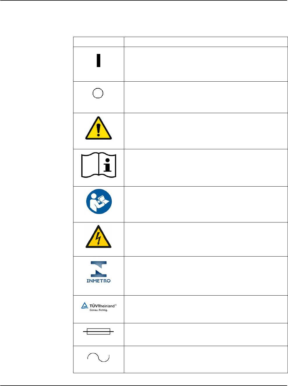
Symbol Definitions The following symbols appear on the WHITESTAR SIGNATURE PRO System
front and back panels and in the software:
Symbol
Definition
Symbol on the power switch indicates power is on.
Symbol on the power switch indicates power is off.
Indicates WARNING; a potentially hazardous situation
which, if not avoided, could result in serious injury.
Indicates that there are important operating and
maintenance instructions included in the operator’s
manual.
Indicates that there are important operating and
maintenance instructions included in the operator’s
manual.
Indicates the presence of uninsulated high voltage inside
the instrument. Risk of electric shock. Do not remove the
instrument cover.
Brazilian National Institute of Metrology, Standardization
and Industrial Quality (INMETRO)
Product Certification Body (OCP) - TÜV Rheinland do
Brasil Ltda.
Indicates fuse.
Single phase alternating current.
RX Only – NGP Z370500 Rev. B 1116
1-16
WHITESTAR SIGNATURE PRO System
1 • Introduction
Symbol
Definition
Indicates isolation of the patient applied part from earth
ground.
Foot pedal connection.
Communications port
Programmable IV pole
Diathermy receptacle
Phaco handpiece receptacle
Vitrectomy cutter receptacle
Potential equalizer used to identify the terminals which,
when connected together, bring the various parts of an
equipment or of a system to the same potential, not
necessarily being the earth (ground) potential, e.g. for local
bonding.
IPX8 is the International Protection code that indicates that
the device is protected against the effects of continuous
immersion in water.
IPX4 is the International Protection code that indicates that
the device is protected against splashing water sprayed at
all angles.
IPX6 is the International Protection code that indicates that
the device is protected against powerful water jets.
Indicates compliance with the Medical Device Directive.
RX Only – NGP Z370500 Rev. B 1116
1-17
WHITESTAR SIGNATURE PRO System
1 • Introduction
Symbol
Definition
Indicates the authorized European Union representative.
Separate disposal/collection required
Indicates manufacturer of the WHITESTAR
SIGNATURE PRO System.
Date of manufacture of the WHITESTAR SIGNATURE
PRO System.
Environment friendly use period in years (RoHS)
Indicates compliance with IEC 60601-1-2:2001,
“Electromagnetic Compatibility Requirements and Tests
for Medical Electrical Equipment.”
ETL Listed Mark issued to those products that have met the
requirements of product safety standards for the United
States and Canada. (ETL formerly Edison Testing
Laboratory)
Universal Serial Bus (USB) port
Federal Communications Commission (FCC)
The FCC regulates interstate and international
communications by radio, television, wire, satellite, and
cable under the FCC’s jurisdiction.
Mark on shipping crate indicating not to open the crate
except by authorized personnel.
RX Only – NGP Z370500 Rev. B 1116
1-18
WHITESTAR SIGNATURE PRO System
1 • Introduction
Symbol
Definition
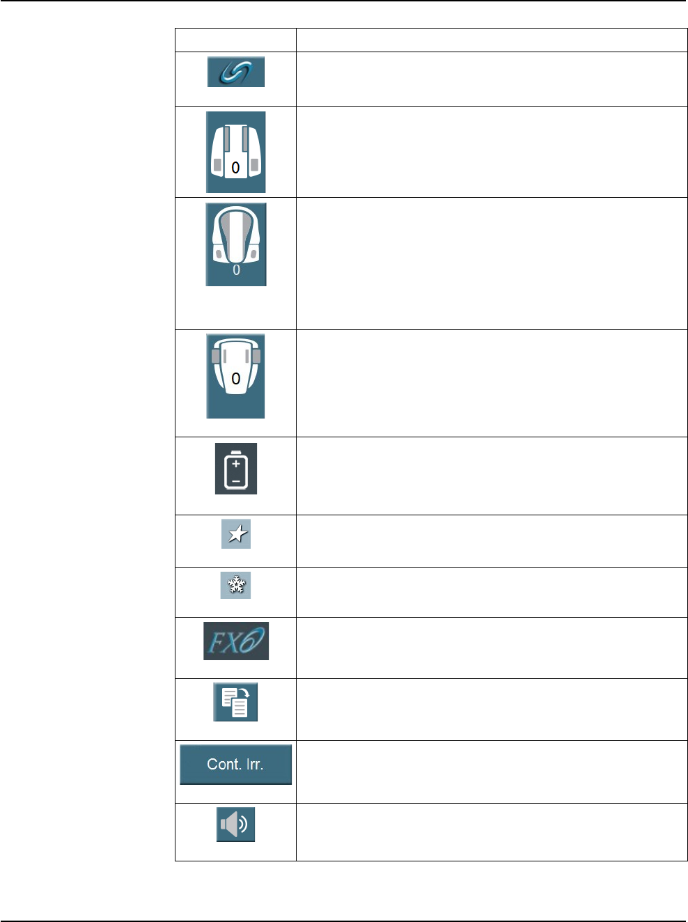
FUSION mode button used to open the CASE and the
Occlusion mode settings screen.
Single Linear Foot Pedal icon. Shows the current position
of the foot pedal as you press the foot pedal. The number
changes when the position of the foot pedal changes. When
pressed, the Foot Pedal Configuration screen opens.
Advanced Control Pedal (ACP) icon. Shows the current
position of the foot pedal as you press the foot pedal. The
number changes when the position of the foot pedal
changes. The letters indicate the location of Aspiration (A),
Irrigation (I), Phaco (P), Reflux (R), WHITESTAR
increment/decrement (WS) and Switch (S). When pressed,
the Foot Pedal Configuration screen opens
Advanced Linear Pedal. Shows the current position of the
foot pedal as you press the foot pedal and the activated foot
switch. The number changes when the position of the foot
pedal changes. When you press icon, the Foot Pedal
Configuration screen opens.
Battery icon on the Advanced Linear Pedal Test screen.
Indicates the battery charge left in the battery.
WHITESTAR Technology is on.
WHITESTAR Technology is on and ICE pulse shaping is
on.
ELLIPS FX handpiece is attached.
Reload - The reload button cycles through the surgeon’s
programs.
Continuous Irrigation - Used to turn continuous irrigation
on or off.
Volume control - When pressed cycles through the volume
settings.
RX Only – NGP Z370500 Rev. B 1116
1-19
WHITESTAR SIGNATURE PRO System
1 • Introduction
Symbol
Definition
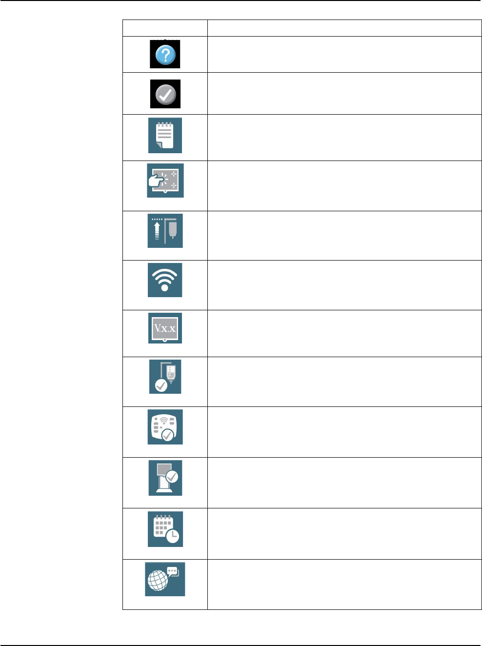
Help - Only active when there is an error. Select this icon to
show possible solutions to clear the error.
Clear Error - Only active when there is an error. Select this
icon after resolving the error. The icon removes the error
from the display.
Event Log - Select this button on the Configuration screen
to view the Event Log.
Touch Screen Calibration - Select this button on the
Configuration screen to calibrate the touch screen on the
system.
Max IV Pole Height - Select this button on the
Configuration screen to set the maximum height the IV
pole can move.
Wireless Setup - Select this button on the Configuration
screen to pair the wireless remote control or the wireless
foot pedals.
View Software Versions - Select this button on the
Configuration screen to view the version of the software
installed on the system.
IV Pole Test - Select this button on the Configuration
screen to test the movement of the IV pole.
Wireless Remote Test - Select this button on the
Configuration screen to test the functionality of the remote
control.
System Self Test - Select this button on the Configuration
screen to run a test of the system.
Set Date/Time - Select this button on the Configuration
screen to set the date and time.
Language - Select this button on the Configuration screen
to select the language used for the user interface.
RX Only – NGP Z370500 Rev. B 1116
1-20
WHITESTAR SIGNATURE PRO System
1 • Introduction
Symbol
Definition
Set Vacuum Units - Select this button on the Configuration
screen to set the vacuum units to either mmHg or kPa.
Surgical Media Center (SMC) - Select this button on the
Configuration screen to format how the SMC starts to
record surgery.
Service Interval - Select this button on the Configuration
screen to view when the next time maintenance is due on
the system.
Import/Export Database - Select this button on the
Configuration screen to import or export a database to or
from the system.
Restore Database - Select this button on the Configuration
screen to restore a database if the current database is
corrupted.
Backup All - Select this button on the Configuration screen
to save data to a USB device.
Restore All - Select this button on the Configuration screen
to restore data from a USB device.
Add Surgeon or Program - Select this icon to add a surgeon
to the list of surgeons or a program to the list of programs.
Delete Surgeon or Program - Select this icon to delete a
surgeon from the list of surgeons or a program from the list
of programs.
Edit Surgeon - Select to edit the surgeon or program name.
Foot Pedal Settings - Select to set up or edit the foot pedal
settings.
Sound Settings - Select to set the volume settings for the
system.
RX Only – NGP Z370500 Rev. B 1116
1-21
WHITESTAR SIGNATURE PRO System
1 • Introduction
Symbol
Definition
Move Doctor Name Up - Select a surgeon name on the list
of surgeons and use this icon to move the doctor’s name up
the list. This can be used to alphabetize the list of surgeons.
Move Doctor Name Down - Select a surgeon name on the
list of surgeons and use this icon to move the doctor’s name
down the list. This can be used to alphabetize the list of
surgeons.
Settings - Select to set the specific surgical program
settings.
More - Opens additional settings screens.
Save - Used to save changes made to settings during
surgery.
Save As - Located on the Program Settings screen. Used to
save the program with a new name.
Restore Program - Located on the Program Settings screen.
Used to change the settings back to the previous saved
settings.
Restore Submode - Located on the Program Settings
screen. Used to change the submode settings to the
previous saved settings.
Lock Program - Select to lock the settings for the selected
program. You cannot unlock a program once the program
is locked.
Copy Program - Select to copy an existing program and
rename to a new program.
Move Program Name Up - Select a program name on the
list of programs and use this icon to move the program’s
name up the list. This can be used to alphabetize the list of
programs for the active surgeon. The name at the top of the
list becomes that surgeon’s default program.
Move Program Name Down - Select a program name on
the list of programs and use this icon to move the
program’s name down the list. This can be used to
alphabetize the list of programs for the active surgeon.

RX Only – NGP Z370500 Rev. B 1116
1-22
WHITESTAR SIGNATURE PRO System
1 • Introduction
System Disposal WEEE
The electronic components of the WHITESTAR SIGNATURE PRO System are
subject to the European Union Directive 2002/96/EC on Waste Electrical and
Electronic Equipment. This directive applies to all electronic equipment in the
European Union only.
The disposal to municipal waste is prohibited for electronic equipment subject to
this directive; this equipment must be treated or recycled. Each component that is
subject to this regulation is marked on the component itself with this symbol:
In some cases where the component’s size prohibits marking (such as handpieces)
the marking can be found on the directions for use and the warranty. Treatment
and/or recycling of the electronic equipment are provided at no cost to you. Please
see the contact information below for disposition of unwanted AMO electronic
equipment.
For disposal of your unit, contact your local AMO subsidiary or the AMO service
center, http://www.abbottmedicaloptics.com/customer-service/overview.
RoHS (Restriction of Hazardous Substances)
For Chinese regulation: Administrative Measure on the Control of Pollution
Caused by Electronic Information Products.
Names and Contents of Toxic/Hazardous Substances or Elements Contained in Products
Toxic/Hazardous Substances or Elements
Assembly
Lead (Pb)
Mercur
y
(Hg)
Cadmium
(Cd)
Hexavalent
Chromium
(Cr6+)
Polybrominated
Biphenyl (PBB)
Polybrominated
Diphenyl
Ethers
(PBDE)
Housing
X
O
O
O
O
O
Power Supply
X
O
O
O
O
O
Motherboard
X
O
O
O
O
O
Rear Panel Assembly
X
O
O
O
O
O
Pneumatics
X
O
O
O
O
O
Monitor
X
O
O
O
O
O
Base Unit
X
O
O
O
O
O
Fluidics
X
O
O
O
O
O
Remote Control
X
O
O
O
O
O
Single Linear Foot
Pedal
X
O
O
O
O
O
Advanced Control
Pedal (ACP)
X
O
O
O
O
O

RX Only – NGP Z370500 Rev. B 1116
1-23
WHITESTAR SIGNATURE PRO System
1 • Introduction
Advanced Linear
Pedal (ALP)
X
O
O
O
O
O
Format of this table is in compliance with SJ/T11364-2006
O: Indicates that this toxic/hazardous substance contained in all of the
homogeneous materials for this part is below the limit requirement in GB/T26572.
X: Indicates that this toxic/hazardous substance contained in at least one of the
homogeneous materials used for this part is above the limit requirement in GB/
T26572.
Restriction of Hazardous Substances in Electrical and Electronic
Equipment (EU RoHS)
All homogeneous materials for the parts contained within the WHITESTAR
SIGNATURE PRO System are below the limit requirement in Directive 2011/
65/EU Annex II, or are addressed by an exemption noted in Annex III or IV.
Registration, Evaluation, Authorization and Restriction of Chemicals
(EU REACh):
For information related to Article 33 of the EU REACh regulation (EC No. 1907/
2006), please refer to Abbott Laboratories' (Abbott) Product Material Information
System (http://pmis.abbott.com). If you have issues logging into the web site,
contact Abbott at abbott.REACH@abbott.com.

RX Only – NGP Z370500 Rev. B 1116
2-1
2 SYSTEM COMPONENTS
Receipt and Inspection Instructions
WHITESTAR SIGNATURE PRO System Components

WHITESTAR SIGNATURE PRO System
2 • System Components
RX Only – NGP Z370500 Rev. B 1116
2-2
Receipt and
Inspection
Instructions
When you receive your WHITESTAR SIGNATURE PRO System inspect the
exterior packaging for any signs of damage that might have occurred during
shipping and record this damage on the shipping documents. If there are any signs
of damage to the exterior packaging, have authorized personnel carefully unpack
the WHITESTAR SIGNATURE PRO System and inspect the system for
damage. If any damage to the package contents has occurred, you must
immediately file a claim with the transporter. The transporters accept claims only
from the recipient (you), not from the shipper (AMO).
Your AMO representative will contact you to schedule both the installation and the
in-service training when you receive your new WHITESTAR
SIGNATURE PRO
System. We suggest that you leave the WHITESTAR SIGNATURE PRO
System in the original packaging. Store the package in a cool, dry
environment
until
the AMO installation personnel arrive to assemble, install, and test your
equipment. Extreme heat, cold or moisture can damage any electronic equipment.
WHITESTAR
SIGNATURE PRO
System Components
Your WHITESTAR SIGNATURE PRO System consists of all or some of the
following components:
• WHITESTAR SIGNATURE PRO System console with a Mayo tray on an
adjustable arm, detachable power cord, and a programmable IV pole
• FUSION pack (disposable)
• Foot pedal and foot pedal cable (Single Linear Pedal (SLP), Advanced Control
Pedal (ACP), or Advanced Linear Pedal (ALP)) (With AC Charger for the ACP
and the ALP)
• Wireless remote control module (With AC Charger)
• Surgical Media Center (optional)
• WHITESTAR SIGNATURE PRO System Operator’s Manual
WHITESTAR SIGNATURE PRO System
2 • System Components
RX Only – NGP Z370500 Rev. B 1116
2-3
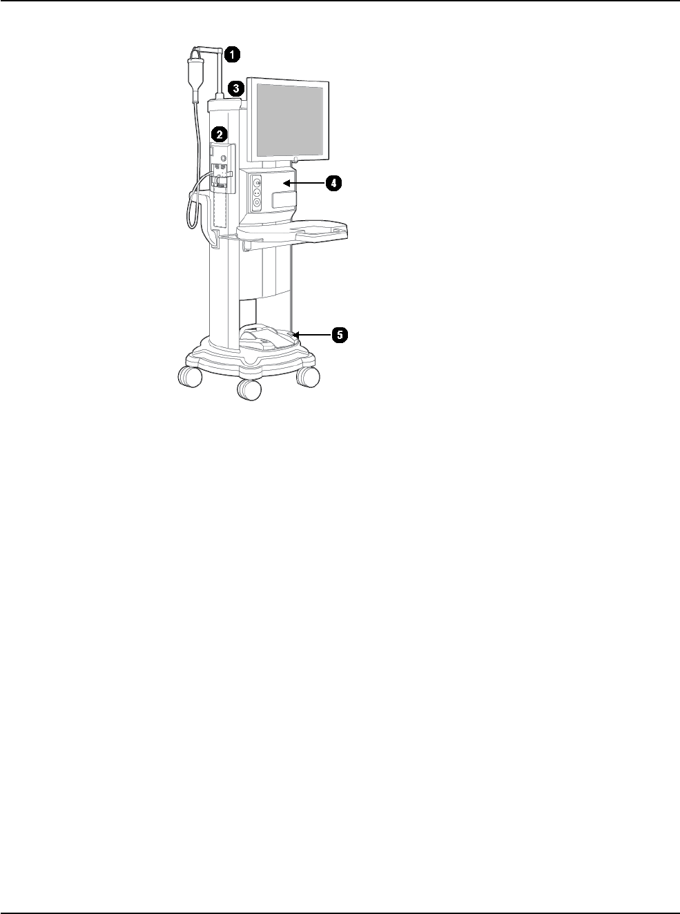
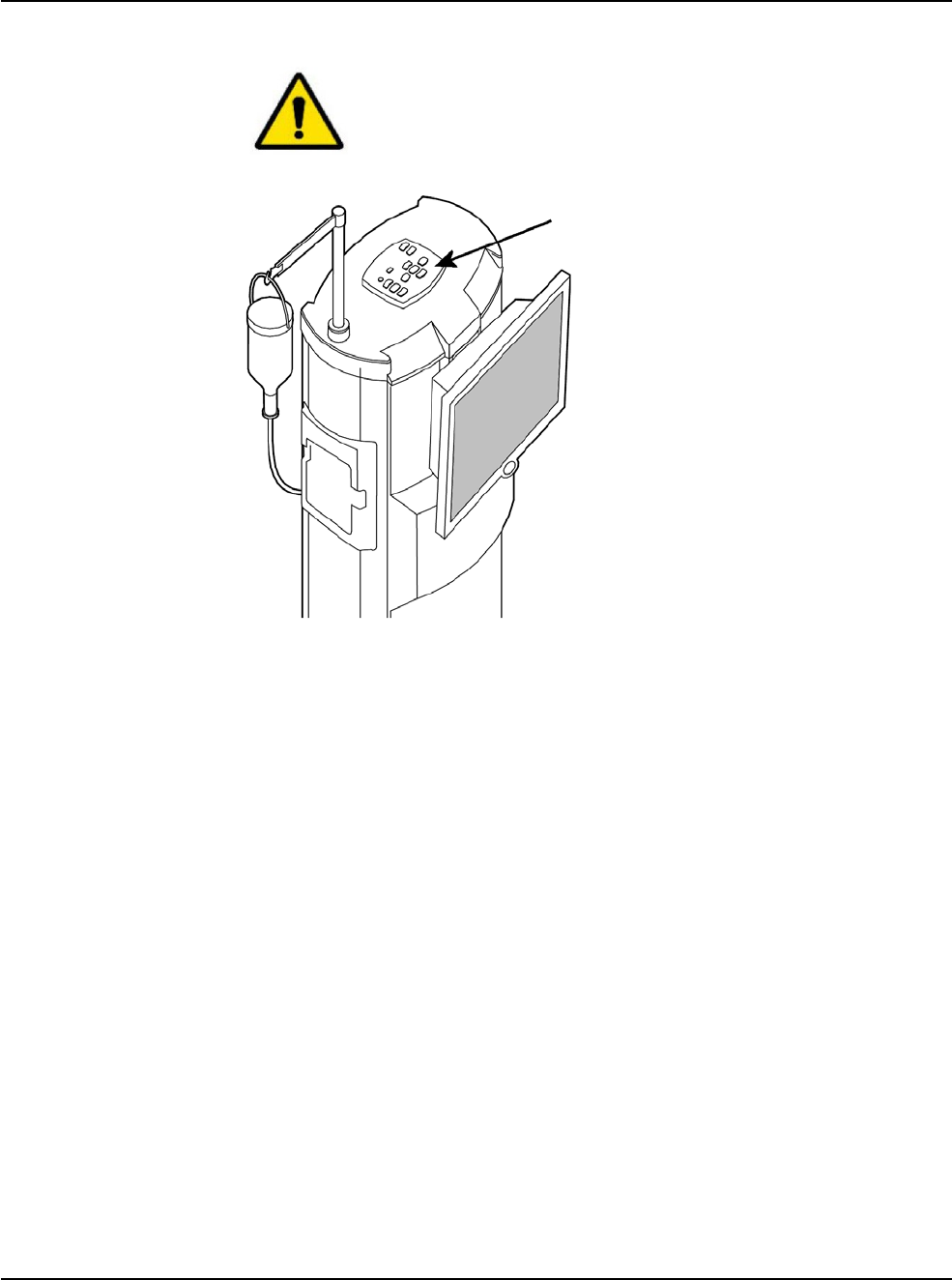
Figure 2.1 – WHITESTAR SIGNATURE PRO System
1. Programmable IV Pole 4. WHITESTAR SIGNATURE PRO System console with Mayo tray
2. FUSION Pack 5. Foot pedal storage
3. Wireless remote control storage
FUSION Packs
Each surgical procedure requires a disposable tubing pack for either the peristaltic
pump or the Venturi pump. The FUSION Pack only works with the peristaltic
pump used in anterior/cataract surgeries. The FUSION Dual Pump Pack works
with both the peristaltic pump and the Venturi pump. With the FUSION Dual
Pump Pack you can select either pump while you are in a surgical case.
The pack contains the following components:
• A pack with irrigation and aspiration tubing (administration set) with an
attached, sealed drain bag
• Test chamber – to test and prime/tune the phaco handpiece
• Mayo tray drape – to cover the Mayo tray and arm
• Monitor drape – to cover the front of the touch screen
WHITESTAR SIGNATURE PRO System
2 • System Components
RX Only – NGP Z370500 Rev. B 1116
2-4
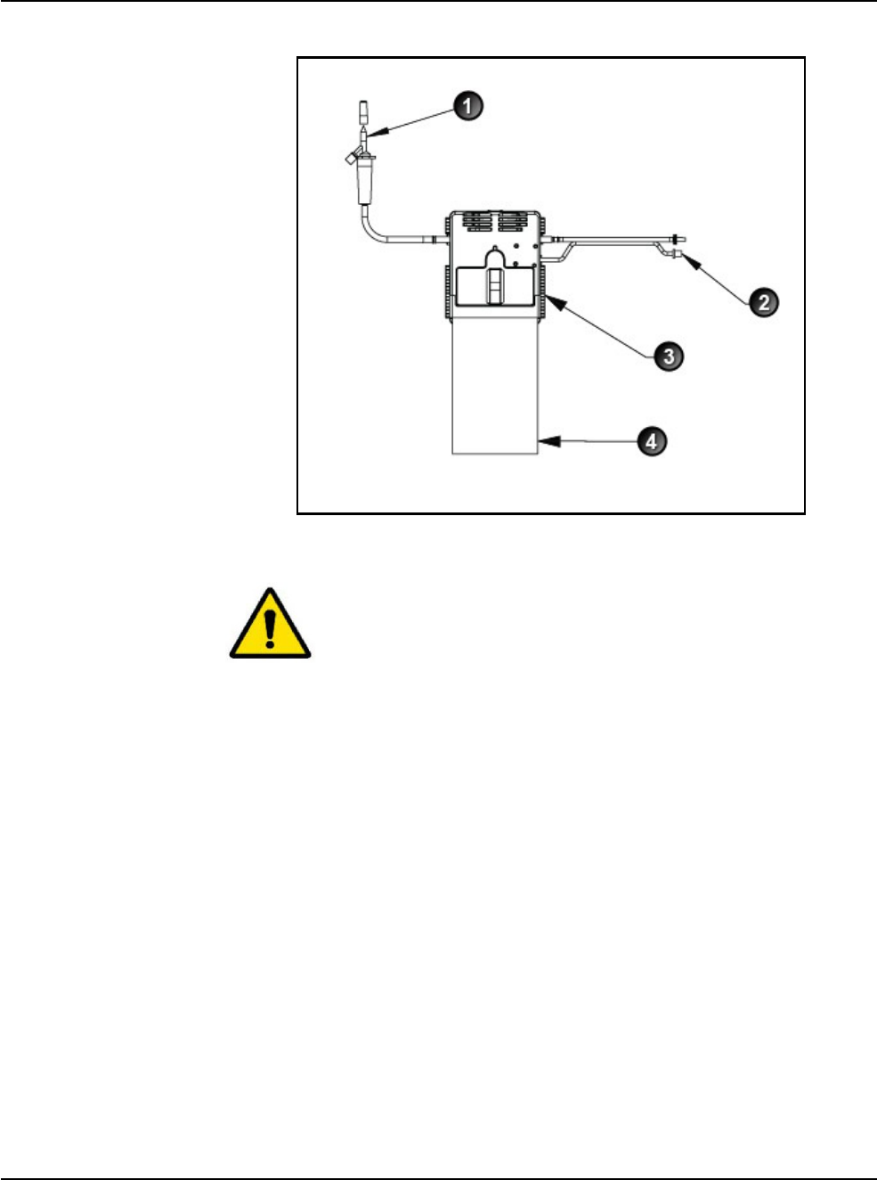
Figure 2.2 – FUSION Tubing Pack
1. To Irrigation Bottle 3. Manifold
2. To Handpiece 4. Drainage Bag
Use proper handling and disposal methods for biohazards when you
dispose of the tubing pack, Mayo tray drape, and monitor drape.
The FUSION Pack (OPO70) allows an inter-connection of the irrigation line to the
aspiration line, so that sterile balanced salt solution can enter the aspiration line and
has no time restriction for reflux as there is no pump reversal.
The FUSION Dual Pump (DP) pack (OPO71) includes support for the vacuum
tank used in the Venturi vacuum system but does not support inter-connecting the
irrigation line to the aspiration line. Therefore, only previously aspirated fluid is
being refluxed.
WHITESTAR SIGNATURE PRO System
2 • System Components
RX Only – NGP Z370500 Rev. B 1116
2-5
Foot Pedal
The foot pedal controls all of the system functions, therefore, it is essential that you
understand the foot pedal operation.
The system software automatically detects if a foot pedal is present and what type
of foot pedal is attached during start up.
The foot pedal settings and adjustments can be selected and preset for all of the foot
pedals on the Foot Pedal Setup screen. Instructions for the foot pedal settings are
given in “Foot Pedal Setup” on page 4-6. The foot pedal housing incorporates a
handle, making the foot pedal easy to grip for repositioning and storage.
The foot pedal cable attaches to the foot pedal connector on the rear of the console.
The Advanced Control Pedal and the Advanced Linear Pedal can also be set
up
with
a wireless connection.
Four to six minutes after the system is shut down and power is turned off, both of
the wireless foot pedals go into a power-save mode.
• To activate the Advanced Control Pedal after you start up the system, touch the
wake-up button on the foot pedal.
• To wake-up the Advanced Linear Pedal after you start up the system, tap the
pedal.
After two hours, when the system is on and the foot pedal switches and treadle are
inactive, the foot pedal goes into a power-save mode:
Note: You must NEVER handle the foot pedal by the cable.
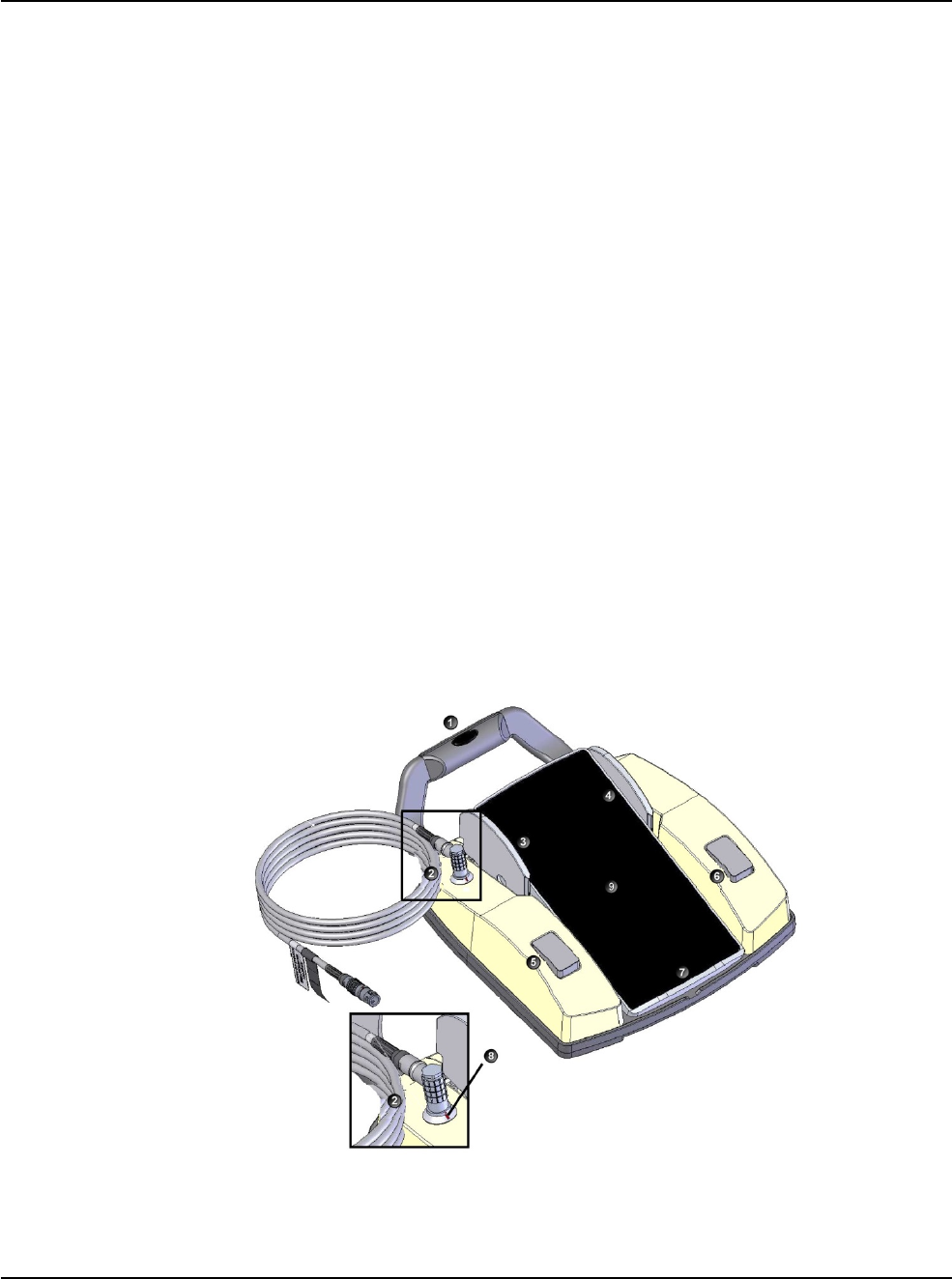
Figure 2.3 – Single Linear Foot Pedal
1. Handle
4. Right toe switch
7. Heel rest
2. Cable connector
5. Left heel switch
8. Cable connector detail
3. Left toe switch
6. Right heel switch
9. Pedal
WHITESTAR SIGNATURE PRO System
2 • System Components
RX Only – NGP Z370500 Rev. B 1116
2-6
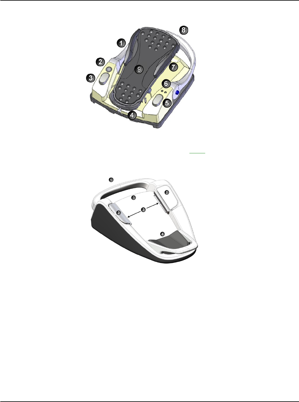
1. Left yaw
5. Right heel switch
7. Right yaw
2. Wake-up button
5. Right heel switch
8. Handle
3. Left heel switch
6. Lights
9. Pedal
Figure 2.4 – Advanced Control Pedal
Figure 2.5 – Advanced Linear
Pedal
1. Handle 4. Heel rest
2. Left and Right Top Switches 5. Pedal
3. Left and Right Side Switches
WHITESTAR SIGNATURE PRO System
2 • System Components
RX Only – NGP Z370500 Rev. B 1116
2-7
Pitch
2.
Yaw
Toe Down/Up
Toe Right/Left
Configurable Ranges
Configurable Ranges
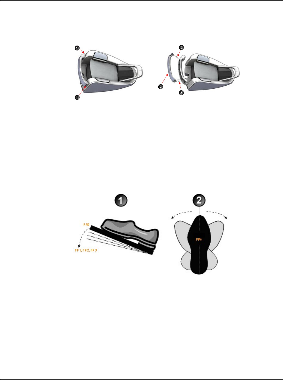
Removing the Handle from the Advanced Linear Pedal
1. To remove the handle, press the clips on either side of the handle.
Figure 2.6 – Foot Pedal Handle Diagram
Removing the Foot Pedal Handle
2. Remove the cover of the handle.
3. Remove the screws and store the screws and handle in a safe place.
Note: Do not lose the handle as it cannot be replaced.
Foot Pedal Operation
The foot pedal has three active “pitch” ranges, which are referred to as positions 1,
2 and 3 (FP1, FP2, FP3). Position 0 is the off position, and position 3 is the fully
pressed position. The ranges are shown below. The Advanced Control Pedal has
two Yaw switches.
Figure 2.7 – Advanced Control Pedal Pitch and Yaw Positions
1.
Note: The foot pedal position determines the function that is delivered by the
handpiece, which depends on the mode selected on the touch
screen.
When
the foot pedal has been attached, place your foot on the pedal and
press to the desired position. The foot pedal settings and programming are
addressed in “Foot Pedal Setup” on page 4-6.
WHITESTAR SIGNATURE PRO System
2 • System Components
RX Only – NGP Z370500 Rev. B 1116
2-8
Programmable IV Pole
The programmable IV pole is controlled by the up and down arrows on the upper
right of the touch screen, next to the bottle height indicator. The buttons on the
remote control and the rocker switch on the side of the console can also be used to
control the IV pole. The height is set on the
Programmable
IV Pole screen. The IV
pole moves at a rate of approximately 7.62 cm per second.
The IV pole is adjustable from 0 to 106 centimeters, and can be set for either inches
or centimeters. The height measurement is relative to the distance from the
irrigation valve to the center of the drip chamber. The IV pole height for each
fluidic mode or submode (phaco, I/A, vitrectomy) is saved in the system memory.
A maximum IV pole height can be set from the Configuration screen.
When a surgery mode is selected, the IV pole automatically moves to the preset
height. To manually adjust the IV pole height, use the up and down arrows on the
touch screen. Manual adjustments to the IV pole can also be made by pressing the
rocker switch located on the side of the console. If a maximum height has been set,
the IV pole does not move above that height.
Wireless Remote Control
The wireless remote control keypad can be used to move between the surgical
modes and submodes. Adjustments to the surgical mode and submode settings can
be made with the remote control. The buttons on the remote keypad work the same
as the controls on the system touch screen.
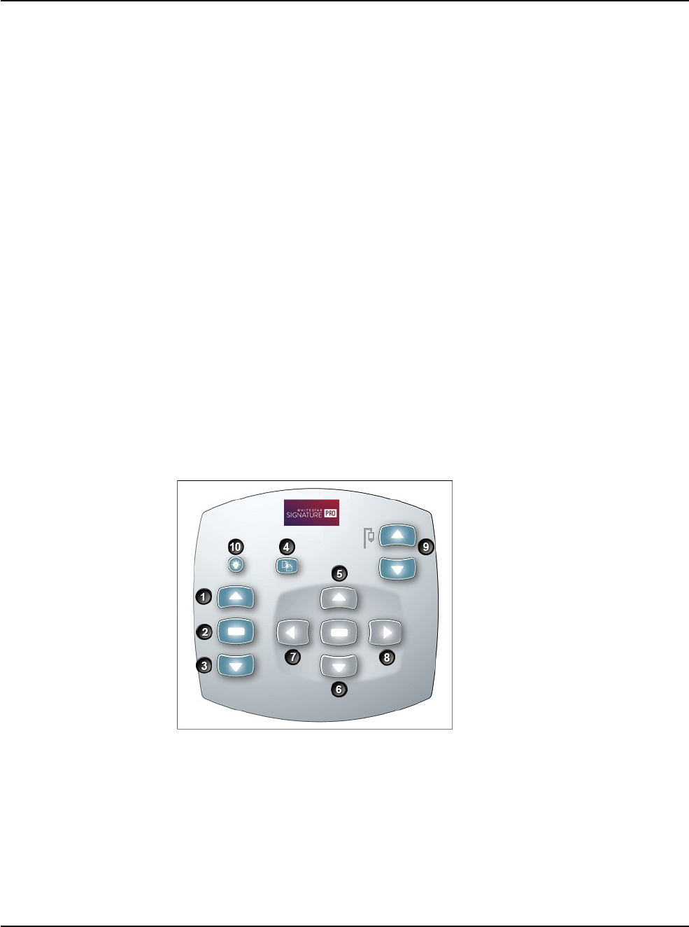
Figure 2.8 – Remote Control Key Functions
1. Previous Major Mode or Previous Submode 6. Down Arrow
2. Mode Select 7. Backward/Left
3. Next Major Mode or Next Submode 8. Forward/Right
4. Reload 9. IV Pole Up/Down
5. Up Arrow 10. Back Light Button
After you turn the system on, press the remote control back light button to activate
the remote control.
Note: After four to six minutes of idle time, the remote control goes into a
power-save mode. To turn the remote control on, press the back light
button.
WHITESTAR SIGNATURE PRO System
2 • System Components
RX Only – NGP Z370500 Rev. B 1116
2-9
WARNING: DO NOT try to replace the wireless remote control
batteries. Call your AMO technical service representative to
replace the batteries.
Figure 2.9 – Wireless Remote Control Module Storage
Surgical Media Center (SMC) - Optional
The Surgical Media Center (SMC) is used to record the surgery and the instrument
settings to be viewed at a later date and time. The surgery is displayed on a monitor
with the instrument settings. The SMC hardware is attached to your system through
the communications port on the rear panel.

RX Only – NGP Z370500 Rev. B 1116
3-1
3 SURGERY START UP
WHITESTAR SIGNATURE PRO System Setup
Front and Rear Panel Connections
IV Pole Setup
Handpiece Setup
Startup
Install the FUSION Pack
Cup Fill
Prime/Tune
Verify Irrigation/Aspiration Balance
Priming for Vitrectomy
Selecting and Changing Mode Parameters
System Check-out
Pre-operative Sterilization
System Shutdown
End Case
RX Only – NGP Z370500 Rev. B 1116
3-2
WHITESTAR SIGNATURE PRO System
3 • Surgery Start Up
WHITESTAR
SIGNATURE PRO
System Setup
This is a general overview of the steps to take to prepare the WHITESTAR
SIGNATURE PRO System for surgery:
1. Attach the power cord to the rear of system. Plug the power cord into a
grounded power outlet.
2. Attach the foot pedal to the rear panel receptacle.
3. Attach the compressed air line to the compressed air receptacle (optional).
4. Turn the system on at the back of the console.
5. Press the on/off button on the touch screen monitor.
6. After completion of the self test, select the surgeon and program.
7. Install the tubing pack.
8. Assemble and attach the required accessories (phaco, vitrectomy, or diathermy
handpieces) and set up the tubing.
9. Prime and tune the handpieces. (See “Prime/Tune” on page 3-11.)
10. Perform the final test of the fluidics and the handpiece integrity with the foot
pedal. (Refer to “Verify Irrigation/Aspiration Balance” on page 3-14.)
Front and Rear
Panel Connections This section shows the front and rear panel connections.
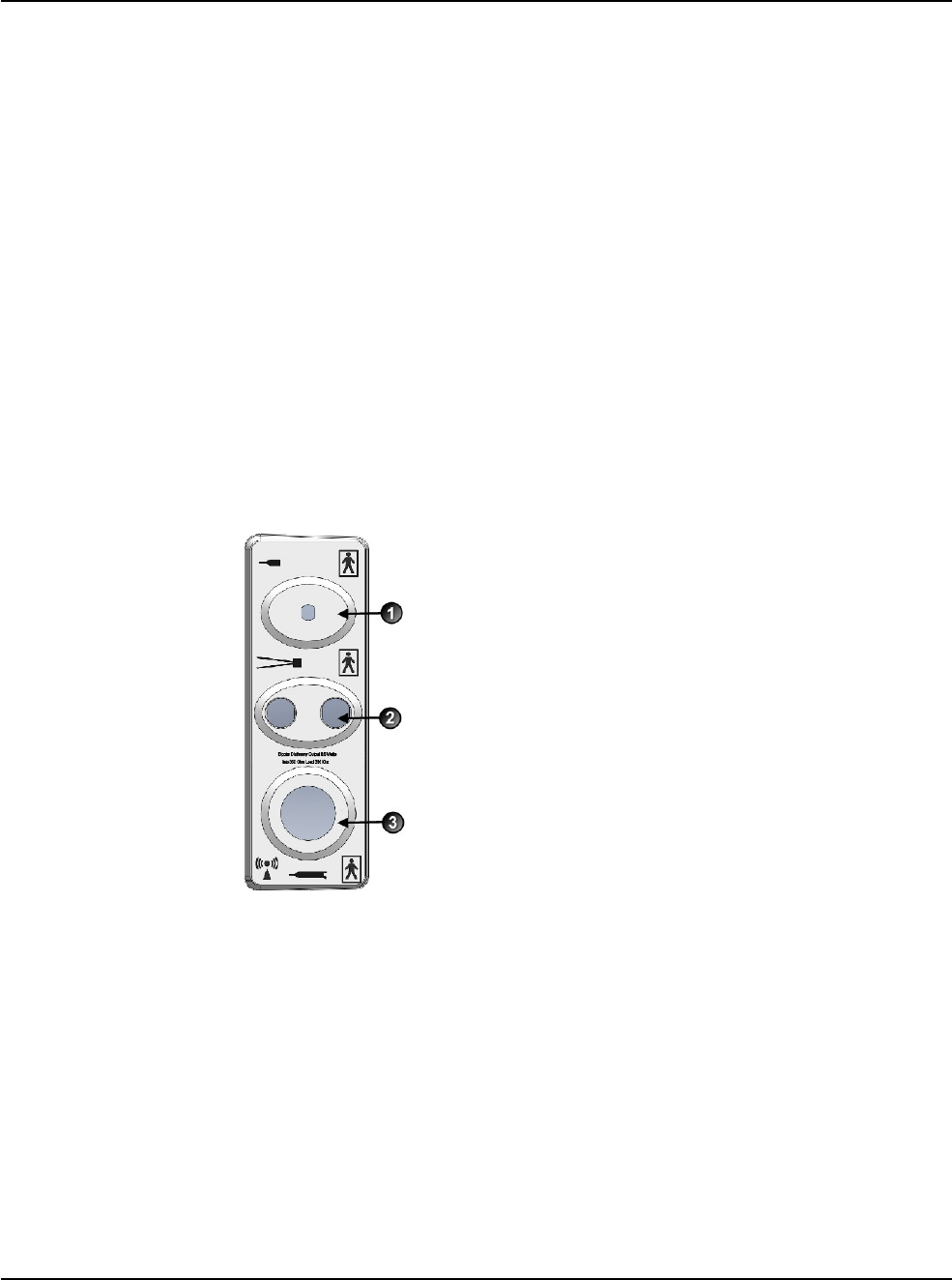
Figure 3.1 – Front Panel Connections
1. Vitrectomy handpiece
2. Diathermy handpiece
3. Phaco handpiece
RX Only – NGP Z370500 Rev. B 1116
3-3
WHITESTAR SIGNATURE PRO System
3 • Surgery Start Up
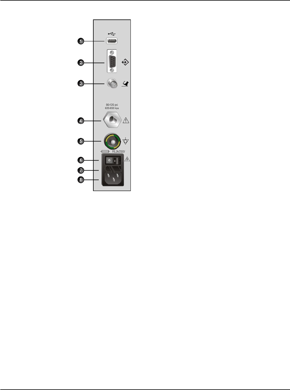
Figure 3.2 – Rear Panel
Connections
1. USB port 5. Potential equalizer
2. Communication port 6. Power switch
3. Foot pedal connector 7. Fuse holder
4. Compressed air 8. Power cord connector
IV Pole Setup IMPORTANT: Before you insert the spike into the bottle, shake the irrigation drip
chamber at the end of the irrigation tubing to confirm that the irrigation valve
moves. If the valve does not rattle, the valve cannot operate properly and irrigation
cannot flow.
The IV pole moves to the appropriate height automatically based on the settings of
the selected surgical mode. Follow these steps to set up the IV pole.
1. Insert the drip chamber spike into a new balanced salt solution bottle.
2. Hang the bottle of balanced salt solution on the IV pole.
3. Squeeze the drip chamber to fill the drip chamber with fluid to the half-full
level.
4. Raise or lower the pole if needed. Use the IV pole up and down arrows on the
upper right of the touch screen. You can also use the rocker switch on the
console.
5. Attach the I/A tubing to the handpiece.
Note: To make sure that the bottle height does not change when you select
I/A after Vitrectomy during surgery, check the box for Bottle Height
Hold on the Vitrectomy Settings screen.
RX Only – NGP Z370500 Rev. B 1116
3-4
WHITESTAR SIGNATURE PRO System
3 • Surgery Start Up
Handpiece Setup This section presents information about setting up the handpieces.
• Phacoemulsification Handpiece Setup
• I/A Handpiece Setup
• Diathermy Handpiece Setup
• Vitrectomy Handpiece Setup
Phacoemulsification Handpiece Setup
WARNING: Sterility assurance is the responsibility of the user.
You must sterilize all non-sterile accessories prior to use.
WARNING: Prior to using any invasive portions of the handpiece
assembly, examine under the microscope for any obvious damage,
oxidation, or the presence of foreign material. Use a backup
handpiece for surgery if there are any questionable characteristics
of the handpiece. Use of contaminated or damaged system
accessories can cause patient injury.
1. Use caution to prevent burns when handling the handpiece directly from
sterilization.
2. Remove the tubing pack and accessories from the packaging and place them in
the sterile area.
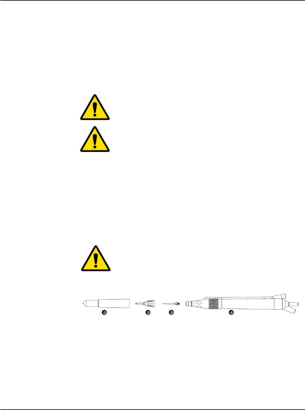
3. Assemble the phaco handpiece as shown below. You need the handpiece,
titanium phaco tip, the appropriate tip wrench, one of the irrigation sleeves, and
the test chamber.
CAUTION: NEVER ATTEMPT TO STRAIGHTEN A BENT
NEEDLE. THIS MIGHT PRODUCE A BROKEN TIP WHEN
YOU APPLY ULTRASOUND.
Figure 3.3 – Phaco Handpiece Assembly
1. Test Chamber 3. Phaco Tip
2. Irrigation Sleeve 4. Handpiece
4. Attach the connector end of the handpiece to the phaco receptacle on the front
of the WHITESTAR SIGNATURE PRO System. Make sure there is no
moisture on the connectors prior to attaching. Moisture prevents the handpiece
from operating properly.
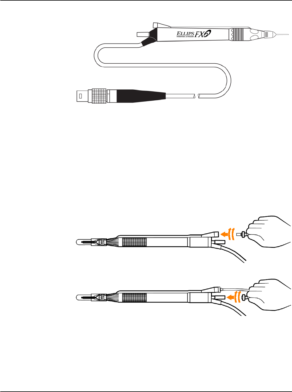
RX Only – NGP Z370500 Rev. B 1116
3-5
WHITESTAR SIGNATURE PRO System
3 • Surgery Start Up
Figure 3.4 – ELLIPS FX
Handpiece
Note: You can use the ELLIPS FX handpiece with WHITESTAR
Technology phaco
settings.
5. Insert the male luer end of the irrigation tubing into the phaco handpiece.
6. Attach the female luer fitting end of the aspiration tubing to the phaco
handpiece.
Note: To protect the patient from contamination, use only:
• sterile tubing
sets
• sterile balanced salt
solution
• sterile
handpieces
Figure 3.5 – Phaco Handpiece Connections
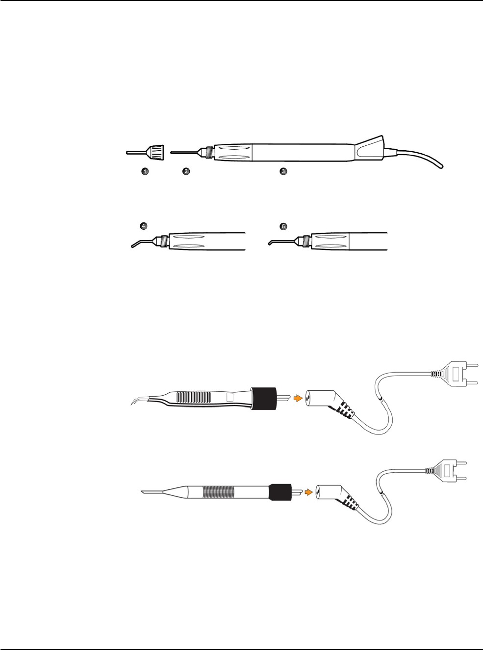
RX Only – NGP Z370500 Rev. B 1116
3-6
WHITESTAR SIGNATURE PRO System
3 • Surgery Start Up
Irrigation/Aspiration Handpiece Setup
Assemble the SOLO Irrigation/Aspiration (I/A) handpiece by attaching the
irrigation sleeve.
Note: The test chamber is provided in the FUSION Pack. The LAMINAR Flow
20 gauge irrigation sleeves can also be used and are available with the
OPOS20L or any 20 gauge LAMINAR phaco tip.
Figure 3.6 – I/A Handpiece Assembly
1. Irrigation sleeve 4. Curved tip
2. Straight tip 5. 45° Tip
3. Handpiece
Diathermy Handpiece Setup
1. Attach the diathermy cord to the diathermy forceps or pencil.
2. Attach the diathermy cord to the diathermy receptacle on the front panel.
Figure 3.7 – Diathermy Forceps
Figure 3.8 – Diathermy Pencil
Note: Other diathermy accessories are regionally available. Contact your AMO
representative.
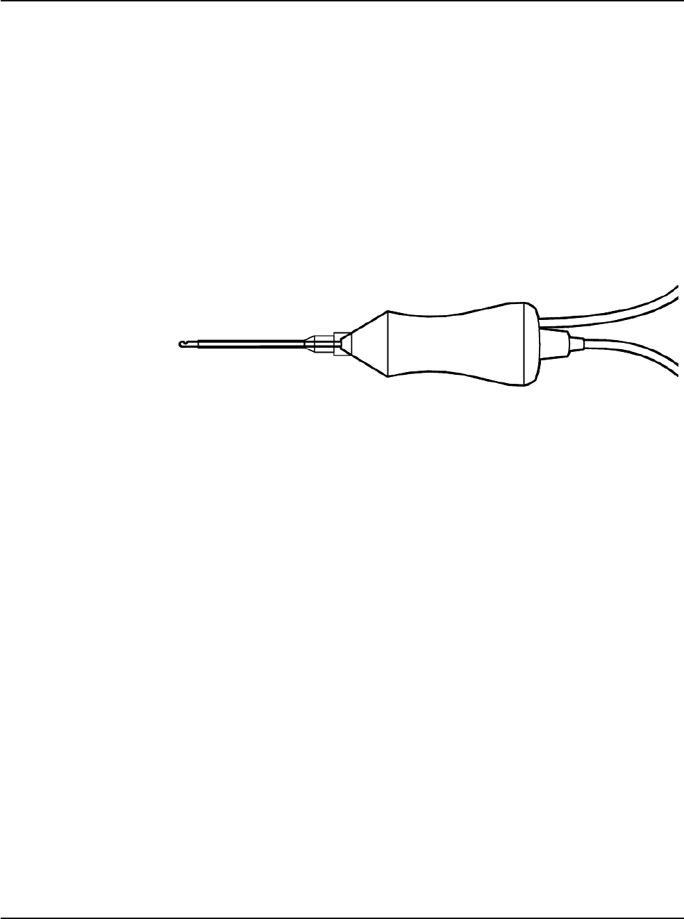
RX Only – NGP Z370500 Rev. B 1116
3-7
WHITESTAR SIGNATURE PRO System
3 • Surgery Start Up
Vitrectomy Cutter Setup
If you need to use vitrectomy during surgery:
1. Attach the vitrectomy cutter as shown below. Vitrectomy requires the
following components:
• I/A Tubing (from FUSION Pack)
• Vitrectomy cutter
• Vitrectomy irrigation sleeve, or a 23 Gauge Limbal Infusion Needle, if
desired.
2. Use the instructions provided with the vitrectomy cutter to assemble the
handpiece.
Figure 3.9 – Vitrectomy Cutter
3. Attach the connector to the vitrectomy receptacle on the front panel.
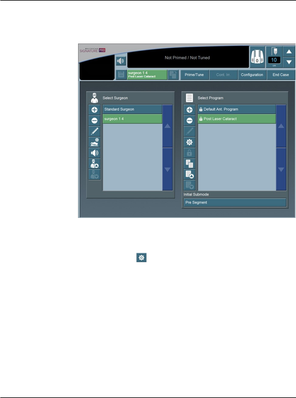
RX Only – NGP Z370500 Rev. B 1116
3-8
WHITESTAR SIGNATURE PRO System
3 • Surgery Start Up
Startup After you have turned on the system, the system performs a series of self tests.
After start up, the screen shows the available surgeons and programs.
Figure 3.10 – Select Surgeon and Program Screen
From the main menu you can:
• Select a Surgeon/Program and begin surgery based on the values of that
program
• Access the Settings screen, where you can edit programs and setup
operating parameters
• Access the Configuration screen to set system parameters
• Access the End Case screen (See “End Case” on page 3-21.).
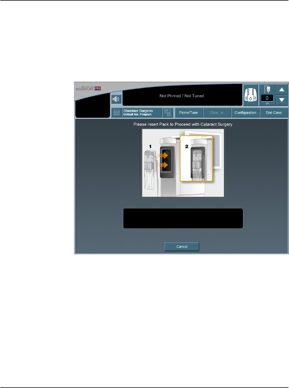
RX Only – NGP Z370500 Rev. B 1116
3-9
WHITESTAR SIGNATURE PRO System
3 • Surgery Start Up
Install the FUSION
Pack 1. After you select a surgeon, you must select a program from the surgeon's
available programs.
Note: The program at the top of the list is the default program for that
surgeon.
2. Select the Prime/Tune button.
Note: If a pack is needed the Install Pack Screen is shown.
Figure 3.11 – Install Pack Screen
3. Install a pack as shown on the screen.
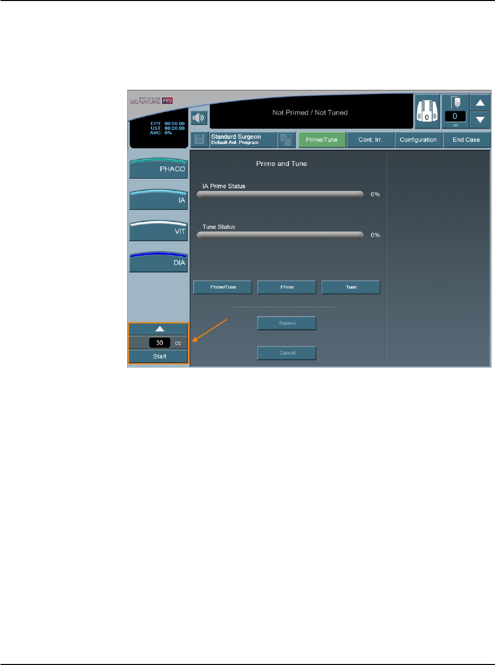
RX Only – NGP Z370500 Rev. B 1116
3-10
WHITESTAR SIGNATURE PRO System
3 • Surgery Start Up
Cup Fill To collect the balanced salt solution:
1. Use the test chamber, a medicine cup, or similar container.
2. Press the Prime/Tune button.
Figure 3.12 – Prime/Tune Screen with Cup Fill Controls Highlighted
3. Use the up arrow to cycle through the three available amounts of solution to be
dispensed. You can choose from:
• 30 cc
• 60 cc
• 90 cc
Note: The fill rate and time is based on using the irrigation tubing with no
handpiece attached and that there is fluid in the tubing. If you use an
attached handpiece to fill the cup, the fluid amount dispensed is less
during the time allowed.
Note: Make sure that you have filled the tubing with fluid using the
Continuous Irrigation feature. If the tubing does not have fluid, the
amount dispensed during Cup Fill may not be the amount selected.
4. Press Start to turn on Cup Fill.
5. Use Stop to turn off Cup Fill. This stops the process before the system
dispenses the requested amount of fluid.
6. Perform a phaco prime/tune. The Prime/Tune screen indicates the progress of
the prime/tune process.

RX Only – NGP Z370500 Rev. B 1116
3-11
WHITESTAR SIGNATURE PRO System
3 • Surgery Start Up
Prime/Tune You must prime/tune:
• before each procedure
• anytime you reattach the phaco handpiece
• after you have inserted or replaced a tubing pack
WARNING: Do not have the handpiece tip in the eye of the
patient when you prime and tune the handpiece.
The prime/tune process fills the I/A tubing with fluid, performs a vacuum check,
and tests and characterizes the phaco handpiece.
You can select Continuous Irrigation to allow fluid to free flow from the bottle to
collect fluid.
The design of I/A Prime allows for a procedure that does not require a phaco
handpiece. The design of tune allows for a quick tune of the phaco handpiece with
an I/A tubing set. You can use tune if you replace a phaco tip during a procedure.
You can shorten the overall prime sequence by selecting Bypass prime. You also
reduce the time to prime the system. You can use Bypass if you used Continuous
Irrigation or primed the I/A tubing.
If you do not properly prime the I/A tubing, errors can occur.
To access the prime/tune routines, press the Prime/Tune button. The console
shows the Prime/Tune screen with all the prime and tune options.
Note: Prime/Tune is a combination of tune followed by an I/A prime.
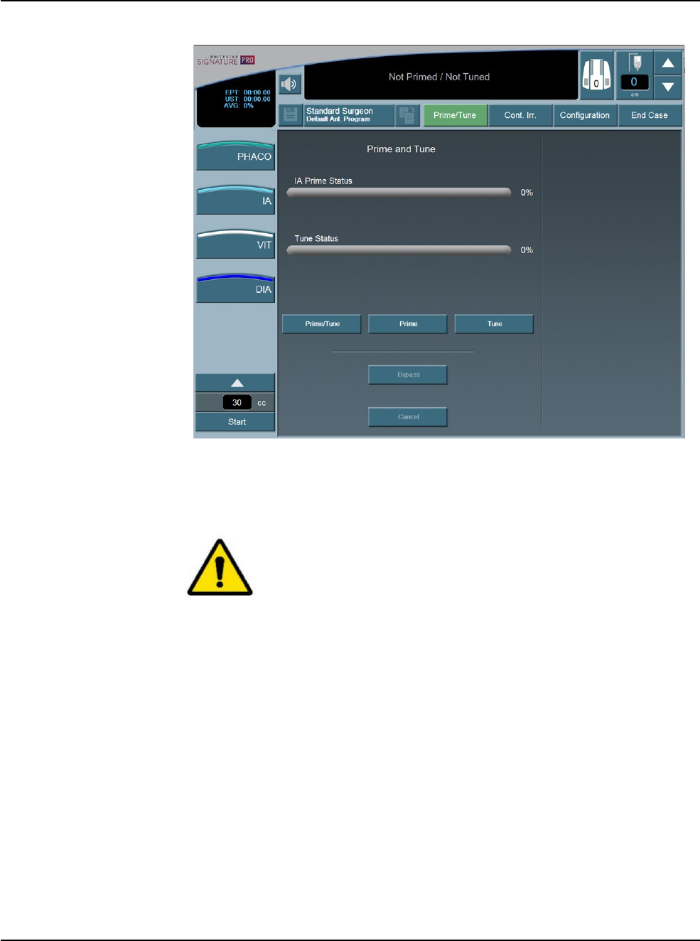
RX Only – NGP Z370500 Rev. B 1116
3-12
WHITESTAR SIGNATURE PRO System
3 • Surgery Start Up
Figure 3.13 – Prime and Tune Screen
The system tracks the successful completion of the prime and tune cycles
independently. If the system needs to be tuned again (new tip, failed tune), you only
need to select and run the tune.
CAUTION: DO NOT ACTIVATE THE PHACO HANDPIECE
AND VITRECTOMY CUTTER WITH THE TIP IN THE AIR.
EXPOSURE OF THE TIP TO AIR DRASTICALLY REDUCES
THE USEFUL LIFE OF THE HANDPIECE. IF YOU
INTRODUCE POWER TO THE PHACO HANDPIECE OR
VITRECTOMY CUTTER, THE TIP MUST BE IN A TEST
CHAMBER FILLED WITH BALANCED SALT SOLUTION, IN
A CONTAINER OF BALANCED SALT SOLUTION, OR
IN
THE PATIENT’S EYE.

RX Only – NGP Z370500 Rev. B 1116
3-13
WHITESTAR SIGNATURE PRO System
3 • Surgery Start Up
Suggestions for Priming the Handpieces
Do not lay the handpiece and the empty test chamber down and have the system fill
the test chamber. When you lay down the handpiece, this allows air to collect in the
test chamber and can produce an error. Point the tip of the handpiece up to reduce
the amount of bubbles.
1. Use Continuous Irrigation to fill the tubing with fluid. Remember to hold the
ends of the tubing over a container to catch any fluid.
2. Use the Cup Fill feature to fill the test chamber with fluid and to eliminate all
air. Remember to remove the test chamber from the handpiece, if needed,
before you start the cup fill process.
3. Place the test chamber over the handpiece tip and the sleeve hub.
4. Attach the tubing to the handpiece.
5. Press the Prime/Tune button, this starts the prime and tune sequences.
• To perform a prime only, press the Prime button.
• To perform a tune only, press the Tune button.
6. Make sure that low ceilings, light fixtures, or equipment do not block the
movement of the IV pole.
7. Watch the fluid fill the drip chamber. The fluid moves toward the handpiece
and fills the test chamber.
8. The display screen indicates the progress of the prime and tune process.
9. As the tubing lines fill, the system software performs functional checks. The
checks include:
• Monitoring for the presence of irrigation flow (bottle height)
• Leaks (via vacuum rise checks)
10. When you attach the phaco handpiece and you select Prime/Tune or Tune, the
system automatically includes a handpiece tuning test concurrently with the
prime cycle.
• At the end of the priming sequence, the system makes an audible sound to
indicate that Prime process is complete.
• At the end of the phaco tuning test, the system makes an audible alert sound
to indicate that Tune process is complete.
11. To discontinue prime or tune during the process, select Cancel.
12. When prime and tune are complete, the system automatically proceeds to the
preprogrammed submode or Phaco 1 operating mode. It is important that you
verify the Irrigation and Aspiration balance prior to operating.
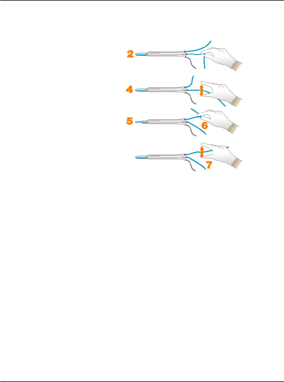
RX Only – NGP Z370500 Rev. B 1116
3-14
WHITESTAR SIGNATURE PRO System
3 • Surgery Start Up
Verify Irrigation/
Aspiration Balance We strongly recommend you verify that you balanced Irrigation/Aspiration
properly for your settings used in surgery.
Figure 3.14 – Irrigation/Aspiration Balance Procedure
To verify irrigation/aspiration balance:
1. In Phaco 1 mode, hold the handpiece at the approximate patient eye level.
Note: The numbers in the drawing Figure 3.14 correspond to the steps listed.
2. Occlude the aspiration line just below the handpiece, while you press and hold
the foot pedal in position 2. Make sure the you attach the foot pedal. (See “Foot
Pedal Setup” on page 4-6.)
3. The actual vacuum level should rise to the preset level.
4. Release the aspiration line and then watch the test chamber to make sure that
the test chamber does not collapse. A slight shallowing of the test chamber is
normal.
5. If the test chamber collapses, raise the IV bottle height or lower the vacuum
setting.
6. Pinch the irrigation tubing at the handpiece and watch for the test chamber to
collapse.
7. Release the irrigation line and the test chamber should fill.
8. Press Reset in the upper left corner of the screen to open the Reset Timers
dialog box. Press Yes to reset the timers. You are now ready to begin surgery.
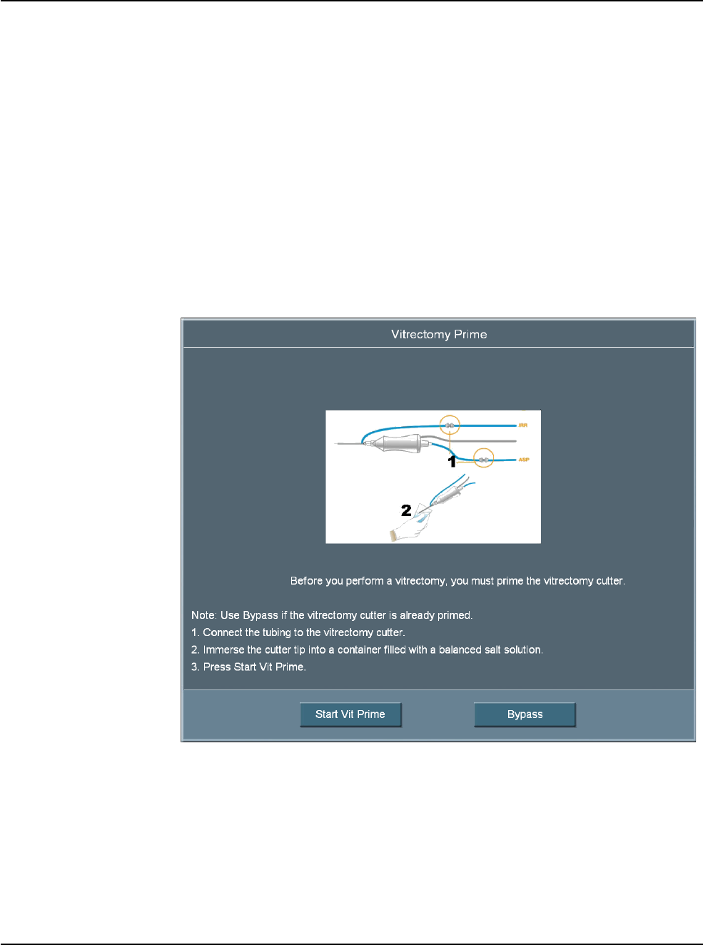
RX Only – NGP Z370500 Rev. B 1116
3-15
WHITESTAR SIGNATURE PRO System
3 • Surgery Start Up
Priming for
Vitrectomy Before you perform vitrectomy, we recommend you prime the handpiece to reduce
the chance of errors. Each time you select vitrectomy mode, a dialog box asks you
to prime the vitrectomy handpiece. If you do not need to prime, press Bypass.
To prime the handpiece:
1. Attach the irrigation tubing and the aspiration tubing of the pack together.
2. Press Prime on the Prime/Tune screen.
3. Press the VIT button to access VIT mode.
4. Follow the instructions on the screen.
5. Press Start Vit Prime. The screen closes automatically after the system primes
the handpiece.
Note: If you must perform vitrectomy in the middle of phaco surgery, perform
steps 3 through 5.
Figure 3.15 – Vitrectomy Prime Procedure
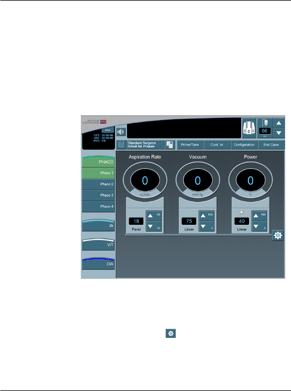
RX Only – NGP Z370500 Rev. B 1116
3-16
WHITESTAR SIGNATURE PRO System
3 • Surgery Start Up
Selecting and
Changing Mode
Parameters
The design of the system's graphical user interface (GUI) and touch screen is for
ease-of-use, consistent look, and maximum informational display during all
operating modes.
Your interface with the system requires only three basic steps, which apply to all
the selections, settings and operations. Once you understand this basic
organization,
you can move quickly and easily through all the system functions and system
operations.
Panels organize the text on the display screen. The top panel shows current status,
configuration options, the bottle height, and the foot pedal icon. The left-side
column lists the operating modes and submodes. The main panel that dominates the
screen shows current operating levels for aspiration, vacuum and power.
Figure 3.16 – Phaco Mode Screen
• To switch operating modes or submodes, press a button in the left panel. The
control panels in the main panel show the operating levels for that mode.
• To make basic changes to the settings, press the up and down arrows to increase
or decrease a value.
• To change other control panel settings, such as Panel or Linear power and
nonzero start, press the Settings button on that control panel. A Settings
screen opens, and you can make your selections.
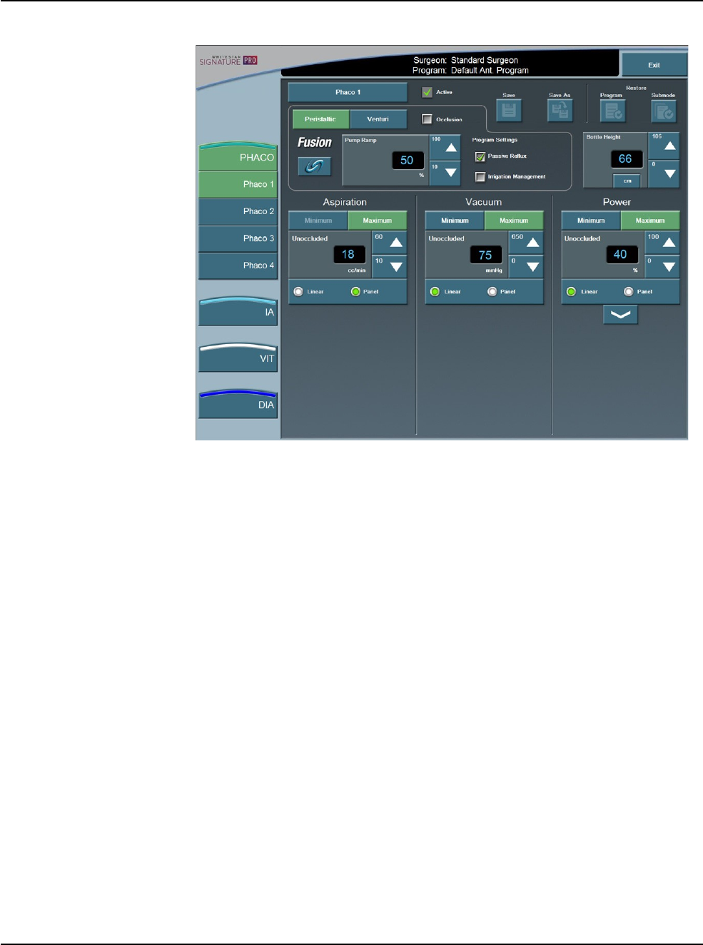
RX Only – NGP Z370500 Rev. B 1116
3-17
WHITESTAR SIGNATURE PRO System
3 • Surgery Start Up
Figure 3.17 – Phaco Submode Settings Screen
System Check-out The purpose of the check-out procedure is to verify that installation of the system is
complete and the system is operating properly. You must perform the check-out
procedure prior to the first case of the day, as outlined in the following steps. You
test the I/A mode and handpiece, then the phaco mode and handpiece, so that the
phaco handpiece (used first) is ready for surgery.
If any of the check-out steps fail, you must repeat the steps. If the instrument still
does not work correctly, refer to Chapter 8, “Error Messages Troubleshooting and
Diagnostics”.

RX Only – NGP Z370500 Rev. B 1116
3-18
WHITESTAR SIGNATURE PRO System
3 • Surgery Start Up
Phacoemulsification
Follow these steps to check the system out for phacoemulsification.
1. Attach the tubing to the phaco handpiece.
2. Screw the phaco needle onto the handpiece, use your fingers to engage the
screw thread, and then use the tip wrench to tighten the needle.
3. Screw the irrigation sleeve over the needle.
4. Place the test chamber over the irrigation sleeve.
5. Prime and Tune the system.
6. Select the phaco mode.
7. Press and hold the foot pedal in position 1.
8. Observe the irrigation flow.
9. Hold the handpiece approximately at the patient’s eye level, and fill the test
chamber with irrigation fluid.
10. Occlude the aspiration tubing just below the phaco handpiece.
11. Press and hold the foot pedal in position 2. The actual vacuum level should rise
to the preset level.
12. Release the occlusion and watch the test chamber to make sure that the test
chamber does not collapse. A dent or dimple in the test chamber is normal.
13. To test irrigation, pinch the irrigation tubing just below the phaco handpiece
and watch for the test chamber to collapse. Release the irrigation tubing and the
test chamber should fill.
14. Press Reset in the upper left corner of the screen to open the Reset Timers
dialog box. Press Yes to reset the
timers.
15. Phacoemulsification check-out is complete.
Irrigation and Aspiration
Follow these steps to check the system out for irrigation and aspiration.
1. Attach the tubing to the I/A handpiece.
2. Select I/A mode.
3. Hold the test chamber near the handpiece tip, press and hold the foot pedal in
position 1
4. Observe the irrigation flow.

RX Only – NGP Z370500 Rev. B 1116
3-19
WHITESTAR SIGNATURE PRO System
3 • Surgery Start Up
Diathermy
Follow these steps to check the system out for diathermy.
1. Attach the diathermy forceps to the cable and the cable to the front panel of the
console.
2. Select the Diathermy mode.
3. Press the foot pedal. You should hear a tone when you press the foot pedal.
Vitrectomy
CAUTION: IF YOU DO NOT HEAR A TONE WHEN YOU
PRESS THE FOOT PEDAL AND VOLUME ADJUSTMENT IS
UNSUCCESSFUL, THE MODE IS NOT FUNCTIONING
PROPERLY. REFER TO Chapter 8, “Error Messages
Troubleshooting and Diagnostics”.
Follow these steps to check the system out for vitrectomy.
1. Attach the irrigation tubing and aspiration tubing of the pack together.
2. Press Prime on the Prime/Tune screen.
3. Press the VIT button to access the VIT mode.
4. Follow the instructions on the screen.
5. Press Start Vit Prime. The screen closes automatically after the handpiece
primes.
6. Observe that:
• irrigation fluid flows
• the aspiration tubing is full and clear of air
• the vitrectomy cutter motor activates (slight sense of motion of the
handpiece)
• the cutter blade operates
7. Vitrectomy check-out is complete.

RX Only – NGP Z370500 Rev. B 1116
3-20
WHITESTAR SIGNATURE PRO System
3 • Surgery Start Up
Pre-operative
Sterilization Prior to each surgical case, sterilize the system instruments with the recommended
sterilization techniques, times and temperatures given in Chapter 7, “Care and
Cleaning”. AMO recommends that you follow the sterilization guidelines to
maximize the life of your system instruments.
System Shutdown The following is a general overview of the steps to be taken to shut the system
down after surgery:
1. Select End Case.
2. Select Shutdown. At the prompt, select Yes.
3. Wait for shutdown sequence to complete.
4. Turn the system off at the back of the console.
5. Remove the power cord from the power outlet.
6. Wrap the excess power cord neatly around the cord wrap on the back of the
console.
7. Use the AC Charging Adapter to charge the ACP or ALP foot pedal.
8. Use the AC Charging Adapter to charge the remote control.
9. Refer to Chapter 7, “Care and Cleaning” for additional information.
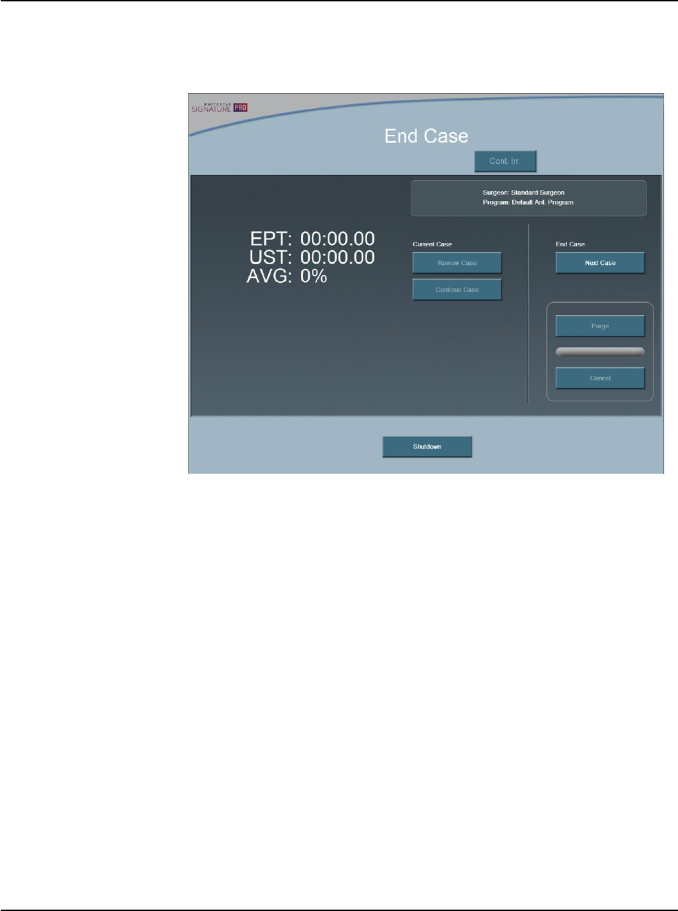
RX Only – NGP Z370500 Rev. B 1116
3-21
WHITESTAR SIGNATURE PRO System
3 • Surgery Start Up
End Case End Case is available in the top panel from any programming or surgical
mode.
End Case allows you to terminate the programming session or surgical case.
Figure 3.18 – End Case Screen
Note: For ease of viewing, the EPT, EFX, UST, and DT times are in a large font
size on the End Case screen. The EFX shows only when you attach an
ELLIPS FX handpiece.
End Case
The timers on the upper left side of the screen indicate:
• Effective Phaco Time (EPT). Effective Phaco Time is ultrasound time as a
weighted total that takes into account the amount of power being used:
• at 100% power: 1 sec. U/S Time = 1 sec.
EPT
• at 50% power: 1 sec. U/S Time = 0.5 sec.
EPT
• Average phaco power (AVG) =
EPT/UST
• Ultrasonic (U/S) time (UST) in foot pedal position 3
• EFX when you attach an ELLIPS FX handpiece
• DT - Diathermy Time
Next Case – Select Next Case to install a new pack.
Note: Use a new bottle of balanced salt solution at the start of each case.
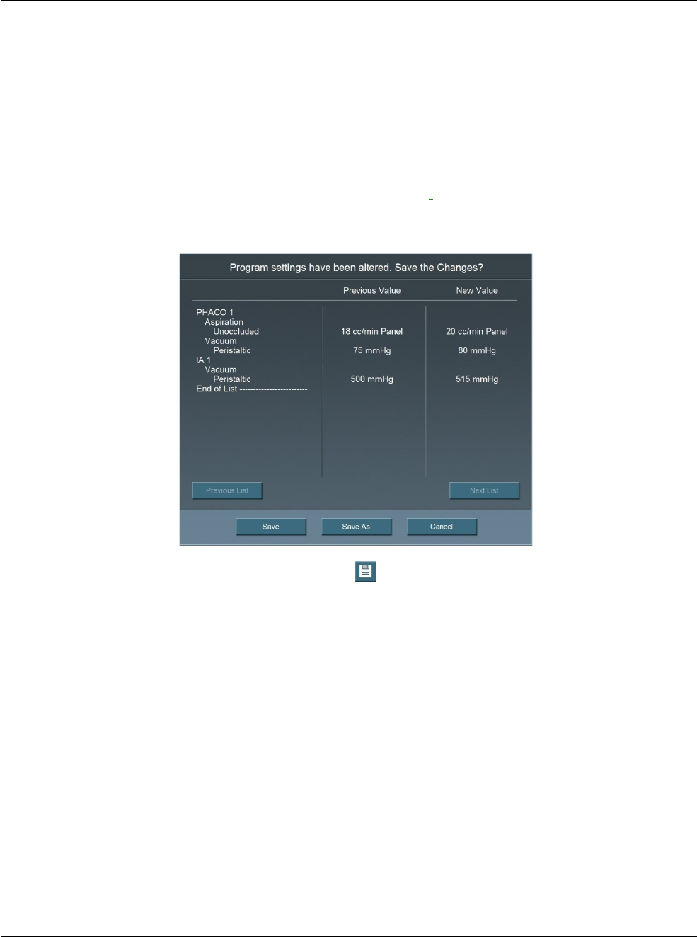
RX Only – NGP Z370500 Rev. B 1116
3-22
WHITESTAR SIGNATURE PRO System
3 • Surgery Start Up
Continue Case – Select Continue Case to return to the current case, after you
selected Review Case.
Purge – Select Purge to remove the fluid from the irrigation and aspiration tubing
before you remove the pack.
Shutdown – Select the Shutdown button to turn the system off. At the prompt,
press Yes to complete the process.
Next Case
If any changes were made to the settings, you are prompted to confirm and save the
changes.
Figure 3.19 – Save Changes Confirmation Screen
Note: You can also select on the main surgical screen to save changes. When
you save changes a confirmation screen is displayed to review the settings.
If
all
of the settings are correct, select Save for the current program. Use
Save As to save to a new program name.
Save - Saves any changes to the current program.
Save As – Saves the program changes (made to an existing program) to a new
program name when you enter a program name.