Jotron AS TA-76XX VHF AM Transmitter User Manual YOUR COMMUNICATION PARTNER
Jotron AS VHF AM Transmitter YOUR COMMUNICATION PARTNER
user manual
TA-7625
1
2
3
4
5
6
7
8
9
10
11
12
13
14
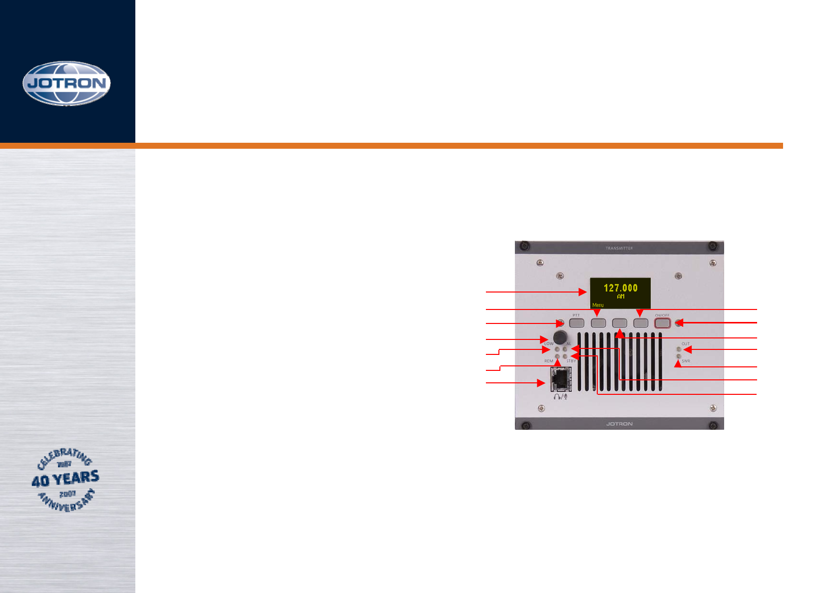
1 DISPLAY
2 FbA (Function button A)
3 PTT button
4 RS (Rotary Switch)
5 Low indicator LED
6 Remote LED
7 Front connector
8 FbC (Function button C)
9ON/OFF
10 FbB (Function button B)
11 OUT LED
12 SWR LED
13 ALARM LED
14 STANDBY LED
VHF Transmitter
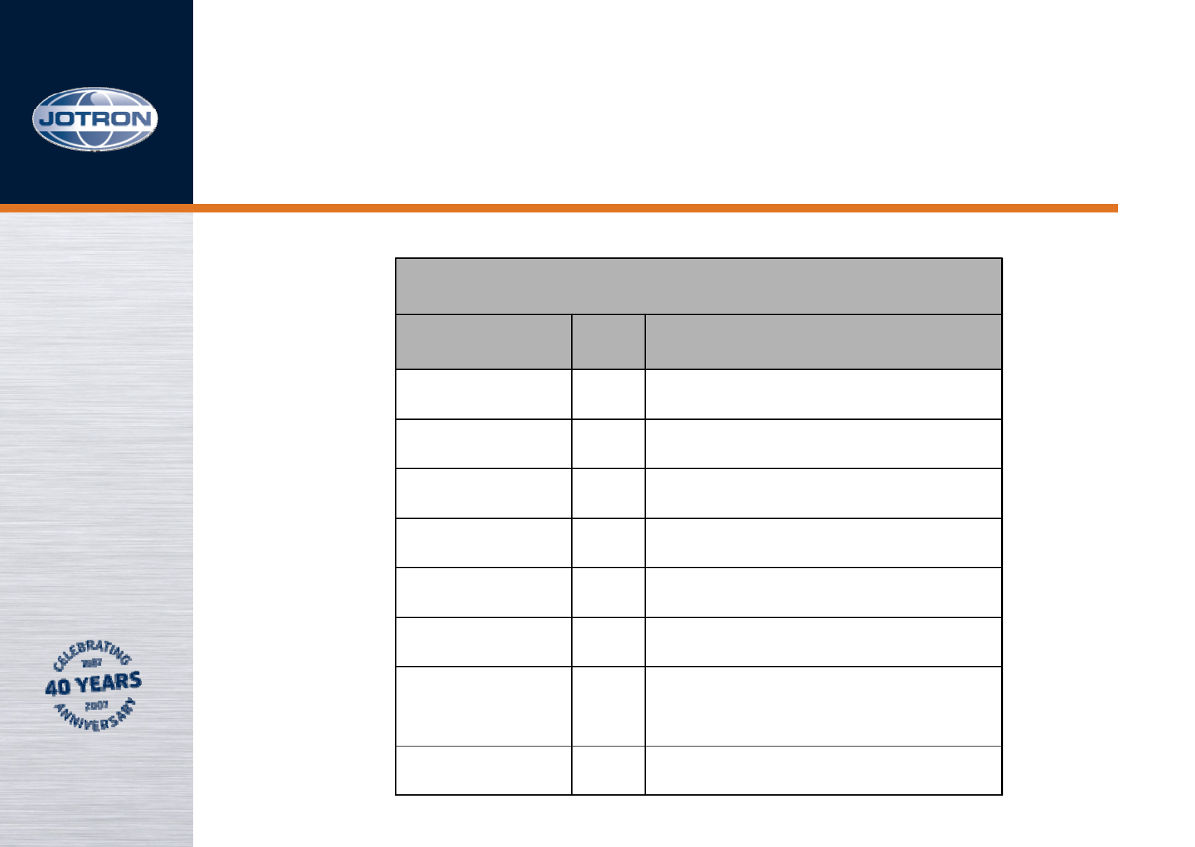
Front RJ45 connector
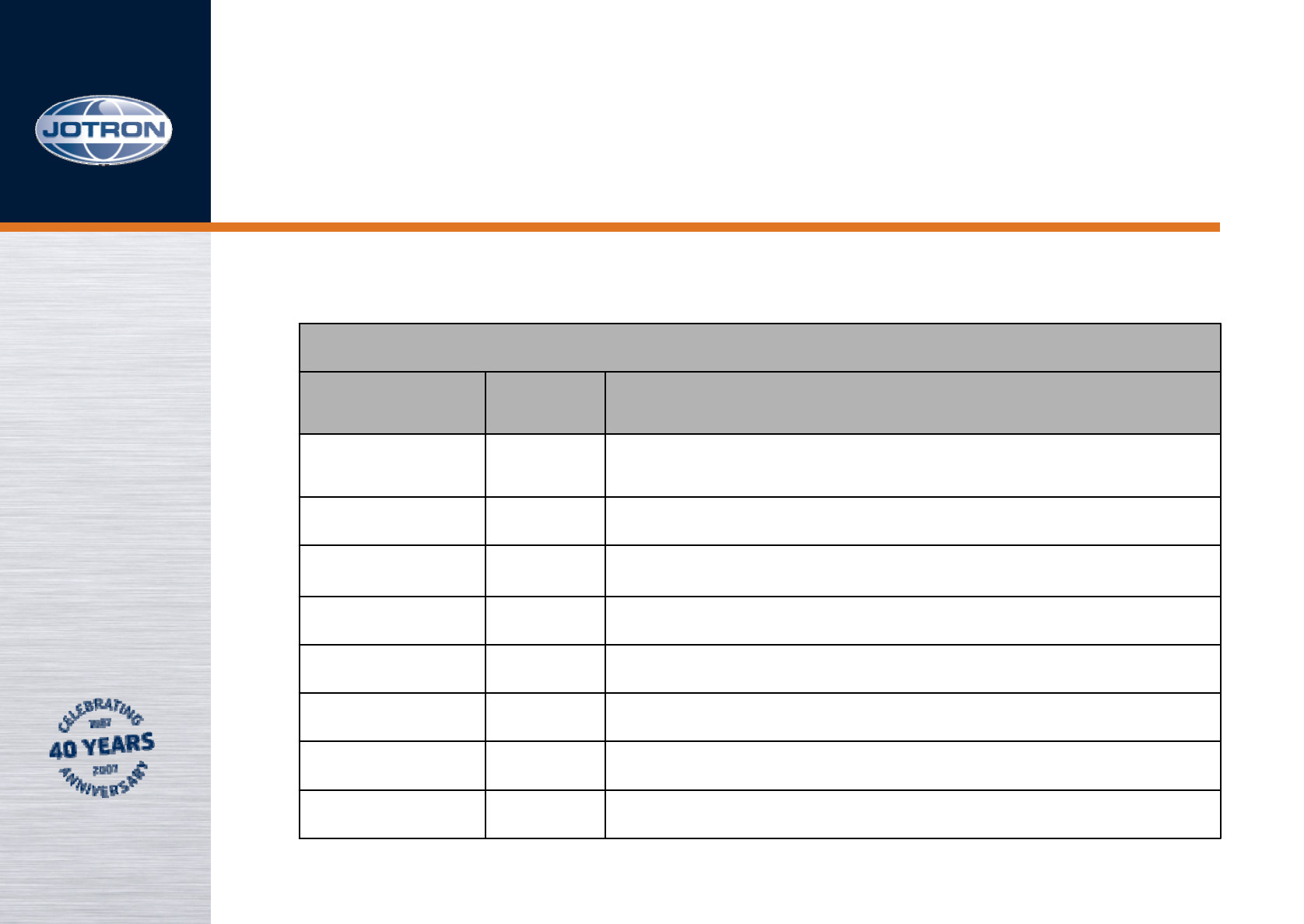
Front Connector, RJ45
Name PIN Purpose
Mic input 1Dynamic. Sensitivity 2.5mV nominal.
Mic GND 2
Headset 3
RS232 4RS232 Tx
RS232 5RS232 Rx
PTT 6Key at GND
+12VDC 7+12 VDC to external equipment (10mA)
GND 8Common ground
TA-7625

Technical data, 1 of 3
Standards; ICAO annex 10, EN300 676(AM, AM-MSK),
EN301 841(VDL2 – Physical layer)
EMC: EN 301 489 – part 22
Environmental: Temperature range -20°C to +55°C (operating) -
40°C to +70°C (storage) Humidity 90% @+40°C
(non condensing)
Shock Transport: IEC-721-3-2, Class 2M3
Vibration Transport: IEC-68-2-32, Class 2M3. IEC-68-2-6
Weight: 3.0 kg
Dimension: 142mm(28TE)(W) * 230mm(D) * 128mm (H)
TA-7625

Transmitter AM 25kHz AM 8.33kHz
Adjacent channel power: >70dB >60dB
Frequency response: 300-3400 Hz 350-2500 Hz
RF modes: 6K80A3EJN 5K00A3EJN
Keying time: < 1,0ms < 1,0ms
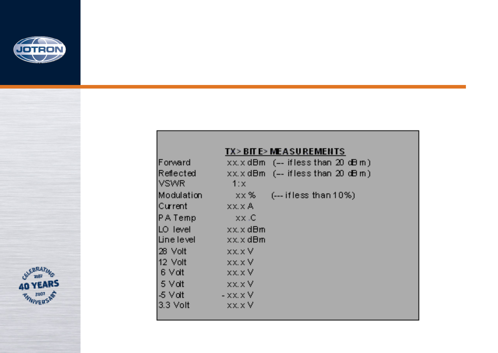
BITE monitoring: VSWR, Voltages, Currents, Levels, Lock
detect, Temperature, Output power, Reflected
power, a.o.
Supply voltage: DC 21.6 - 31.2VDC negative ground
Power consumption: < 280VA
MTBF: >10 years / unit
MTTR: <30 minutes at lowest replaceable unit
Technical data, 2 of 3
TA-7625

Technical data, 3 of 3
Data ports: RS232, RS485, 100/10BaseT
Protocol: (SNMP v.2) Simple Network Management
RS232/RS485 Jotron proprietary
Output power: 1-50W ±1dB
Duty cycle: 100% continuous operation @ ambient
below 40ºC
VSWR: 1: infinity
Intermodulation protection: >40dB when interfering signal is
decoupled with at least 30dB
Modulation level: Up to 95%
Distortion: < 3%
Line input: 600Ω, -36 to +7 dBm
TX timeout: 15s to 5 min in 1s steps
Inband keying: Configurable tones 100 – 5000Hz
Carrier offset: 2, 3, 4, or 5
Wide band noise: <150dBc @ 1% frequency offset
TA-7625
Menus, 1 of 16
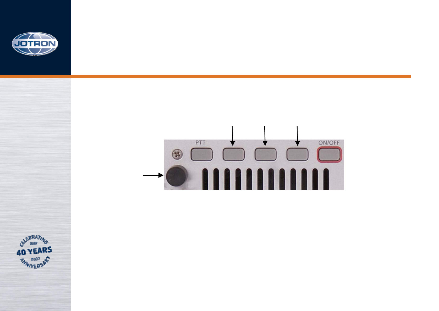
FbA
RS
FbB FbC
NOTE: RS can be pushed and turned.
The radio is controlled through an advanced menu system.
The access level for each menu is restricted by a user parameter.
The System Operator can change all user parameters from SNMP, or
from the menu using a hardware key.
TA-7625

Menus, 2 of 16
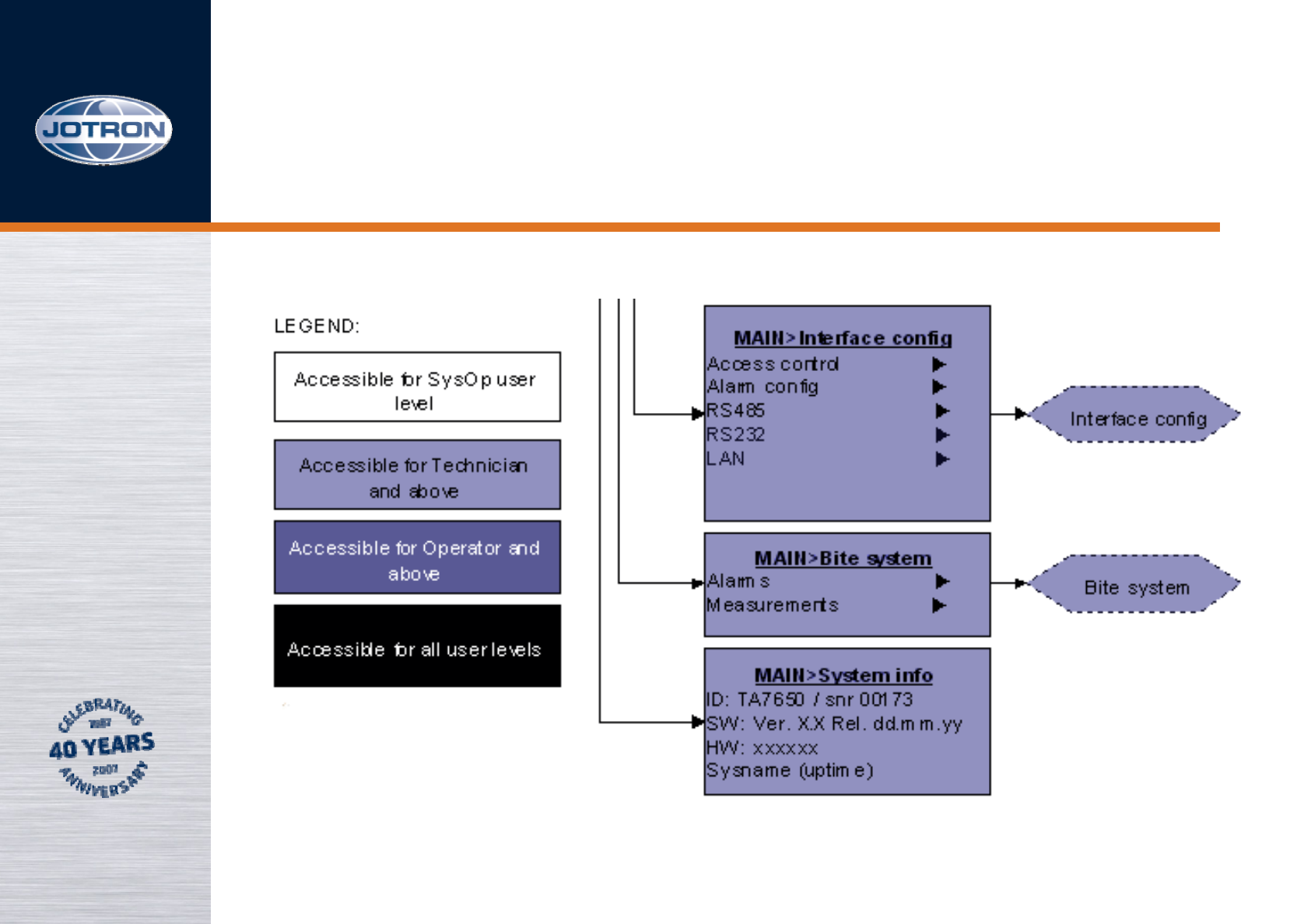
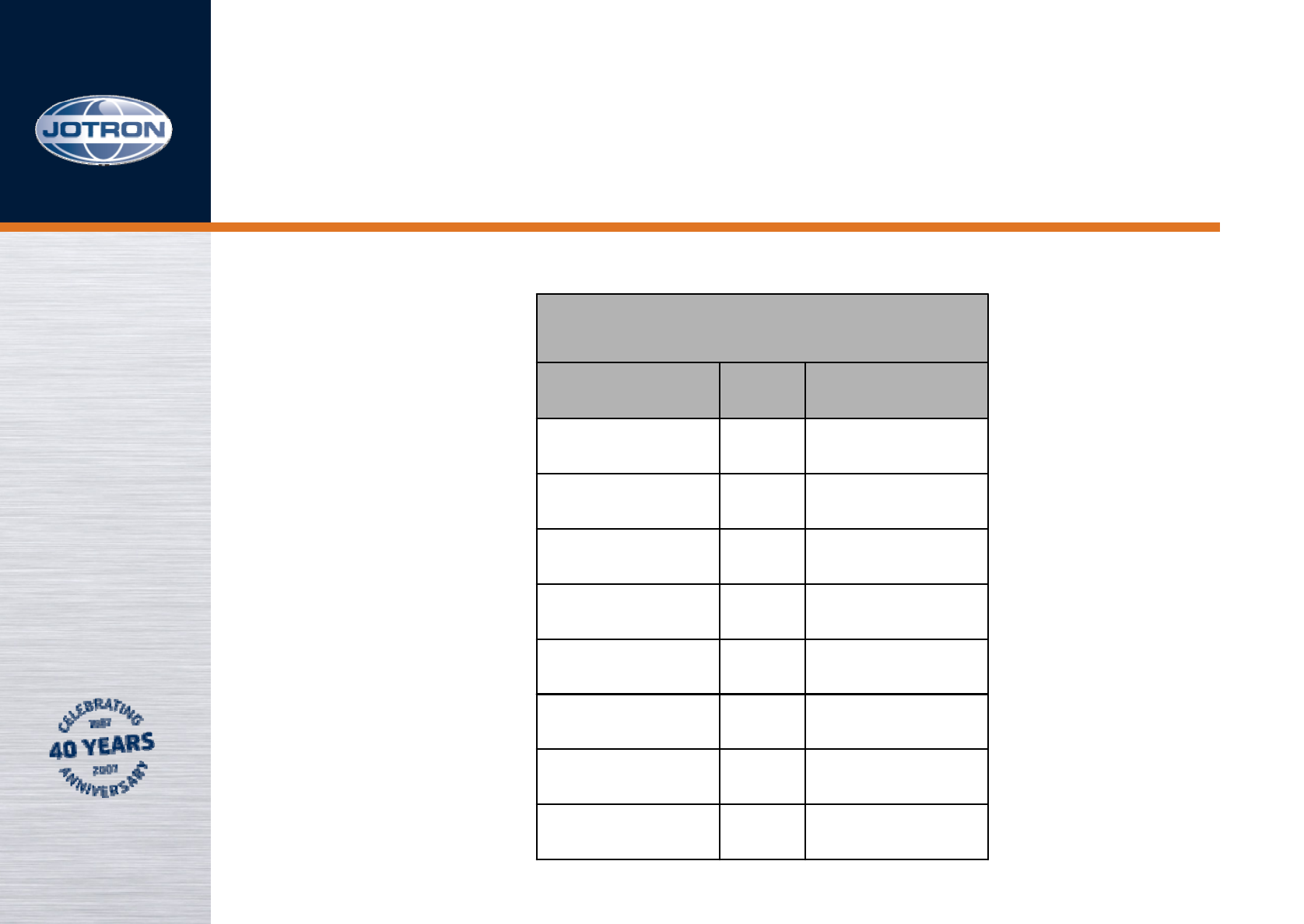
User
parameter: Name of menu: Access and restrictions:
1System Operator Full access to all parameters
(R/W by System Operator)
2Technician Access to some settings in TX
menu system + bite (R/O)
3Operators Access only to Volume,
Frequency and memory store
and recall
4Restricted Restricted to Volume and
memory recall
There are four user access levels:
TA-7625
Menus, 3 of 16
Push RS
When operated locally, the operator has full access to all facilities
using the various controls at the front panel.
TA-7625
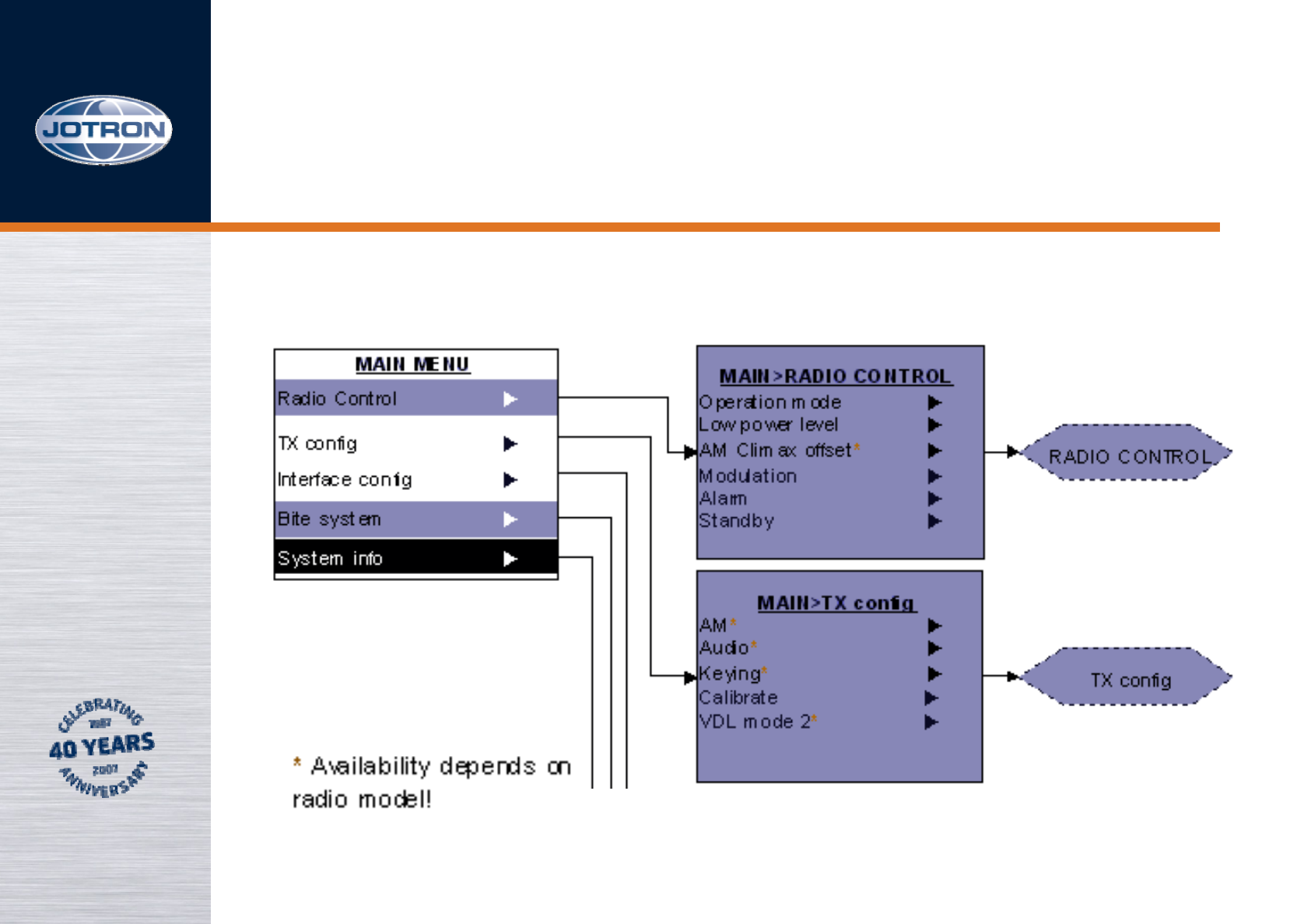
Menus, 4 of 16
TA-7625
Menus, 5 of 16
TA-7625
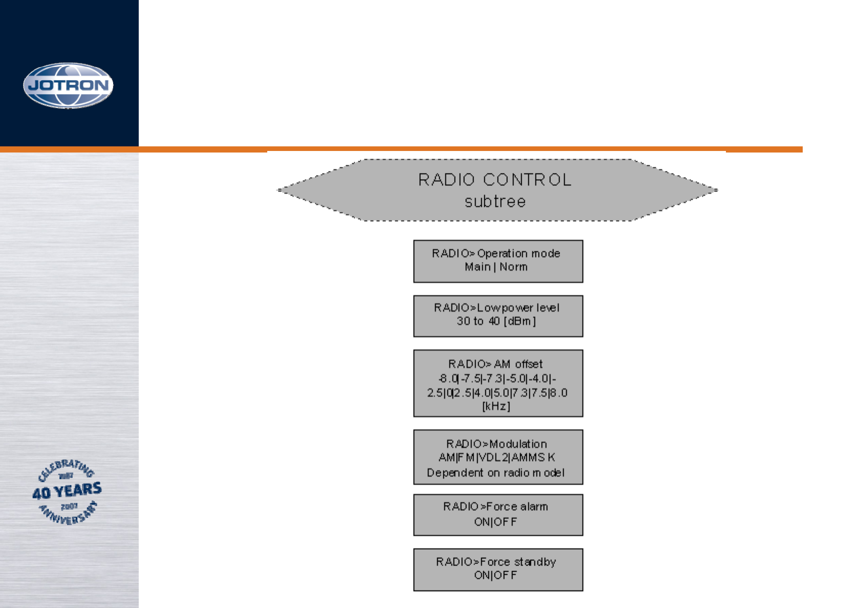
Menus, 6 of 16
TA-7625
Menus, 7 of 16
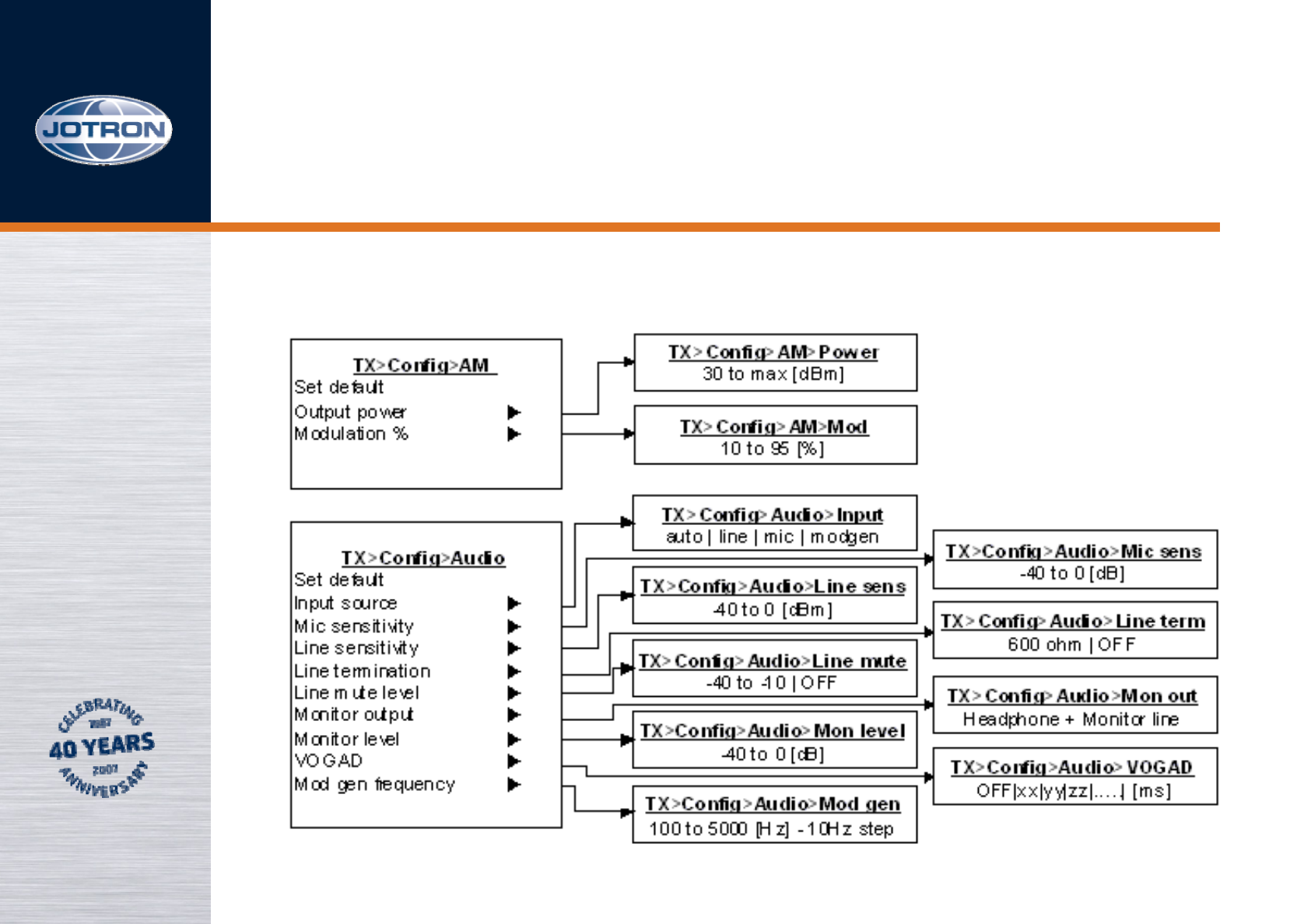
TX config subtree menu, 1 of 2
TA-7625
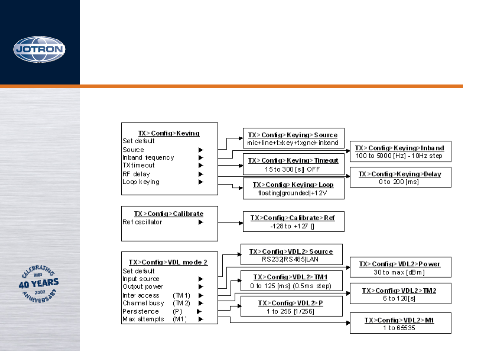
Menus, 8 of 16
TX config subtree menu, 2 of 2
TA-7625
Menus, 9 of 16
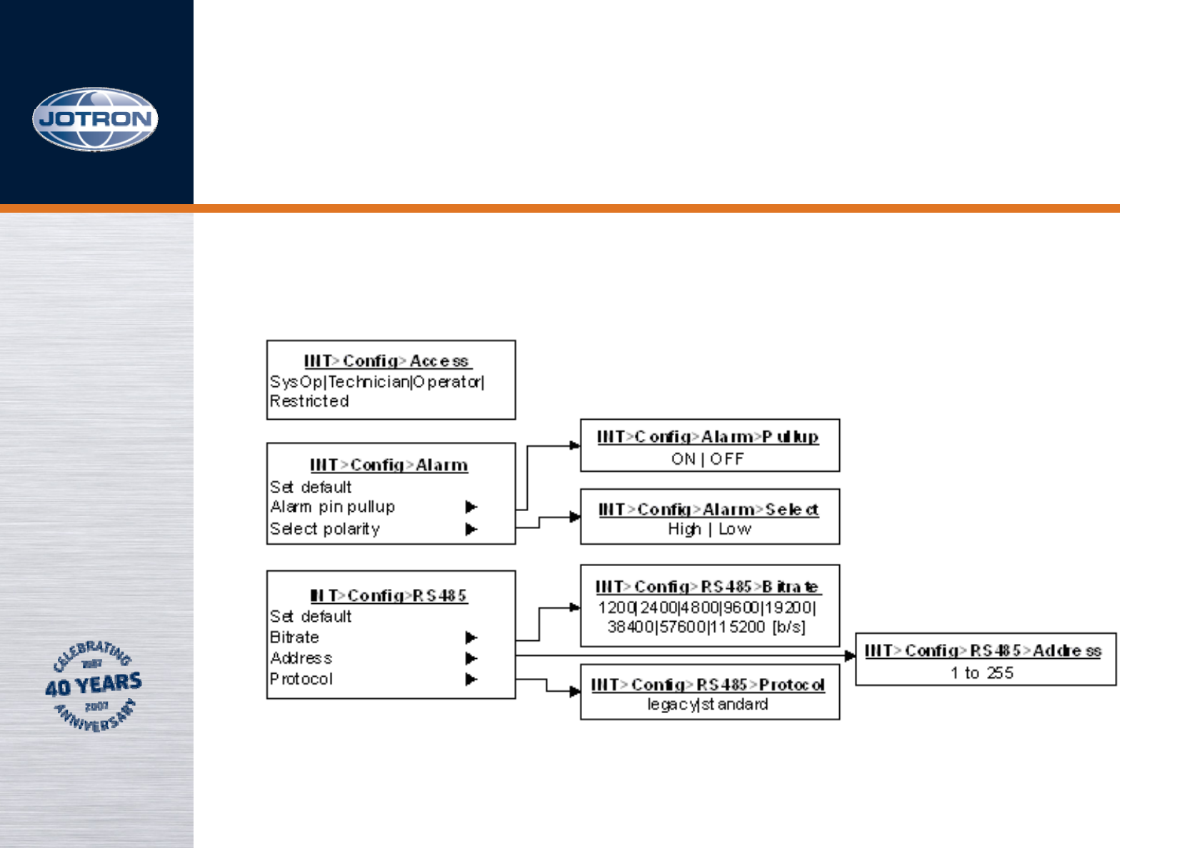
Interface config subtree menu, 1 of 2
TA-7625
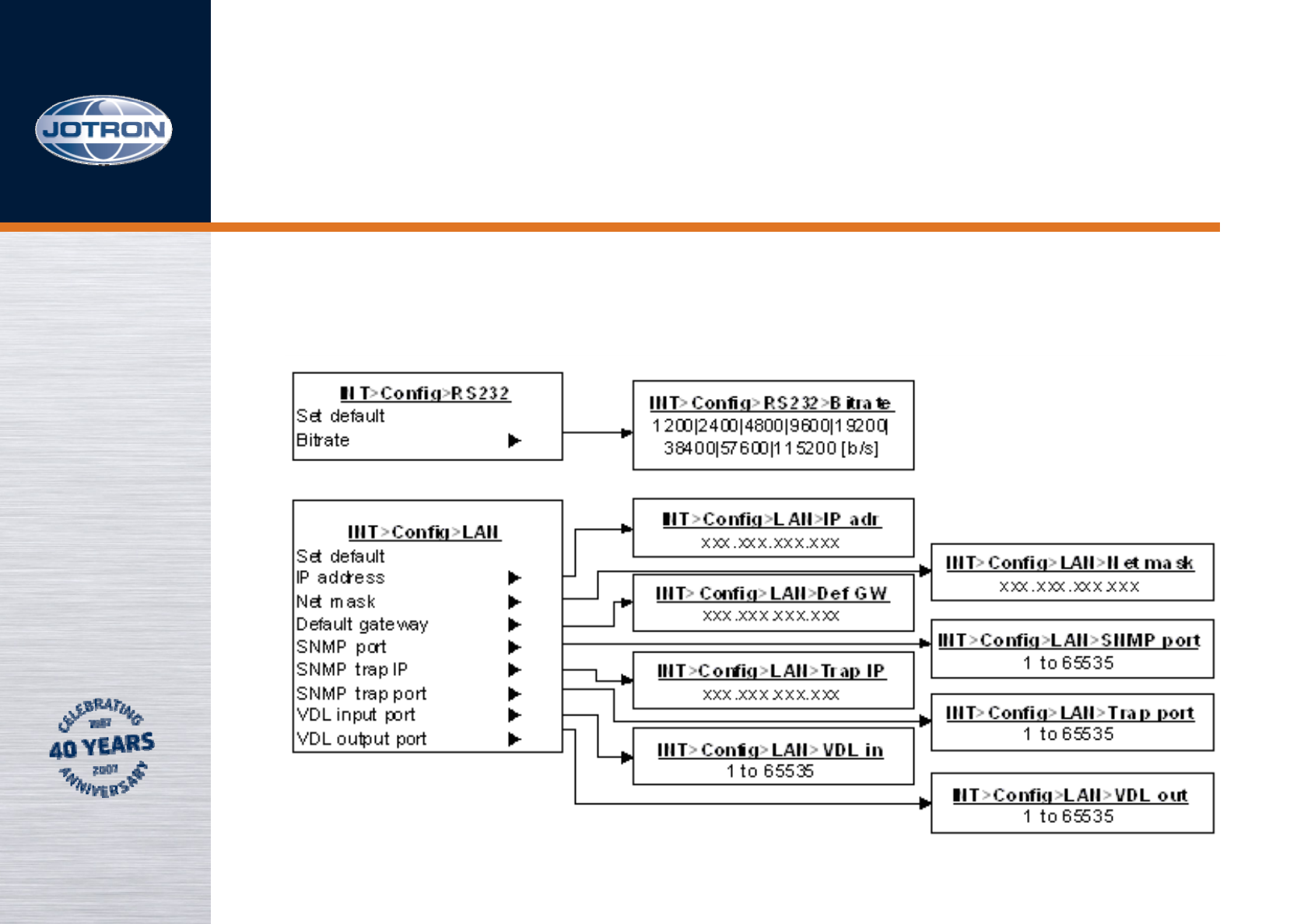
Menus, 10 of 16
Interface config subtree menu, 2 of 2
TA-7625
Menus, 11 of 16
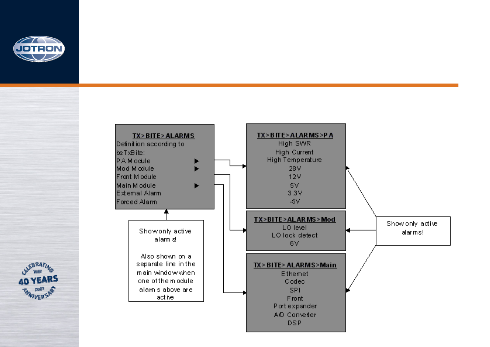
Bite system subtree, 1 of 2
TA-7625
Menus, 12 of 16
Bite system subtree, 2 of 2
TA-7625

Menus, 13 of 16
To maneuver in the menu systems, use the up-button FbA,
the down-button FbB or (preferably) turn the RS.
The different submenus are selected by pressing the rotary
switch and turning up/down until the desired menu is
reached. (FbA, FbB and FbC may be used as well)
To return to previous menu, press RS (or FbC) when “ ,,,” is
selected in the present menu.
The TA-7650 will enter the Operator menu when turned
“ON”.
TA-7625
Menus, 14 of 16
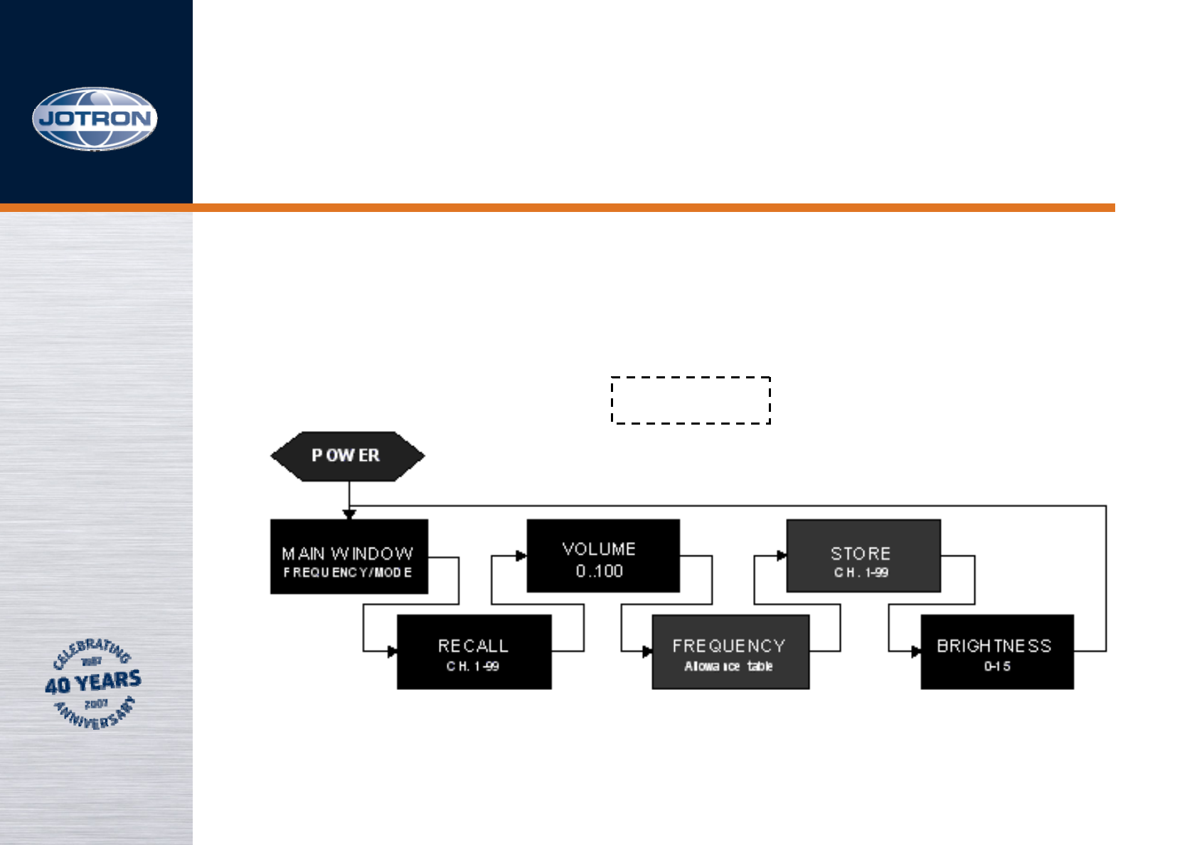
Operator menu, 1 of 3
Press RS
Press RS
PressRS
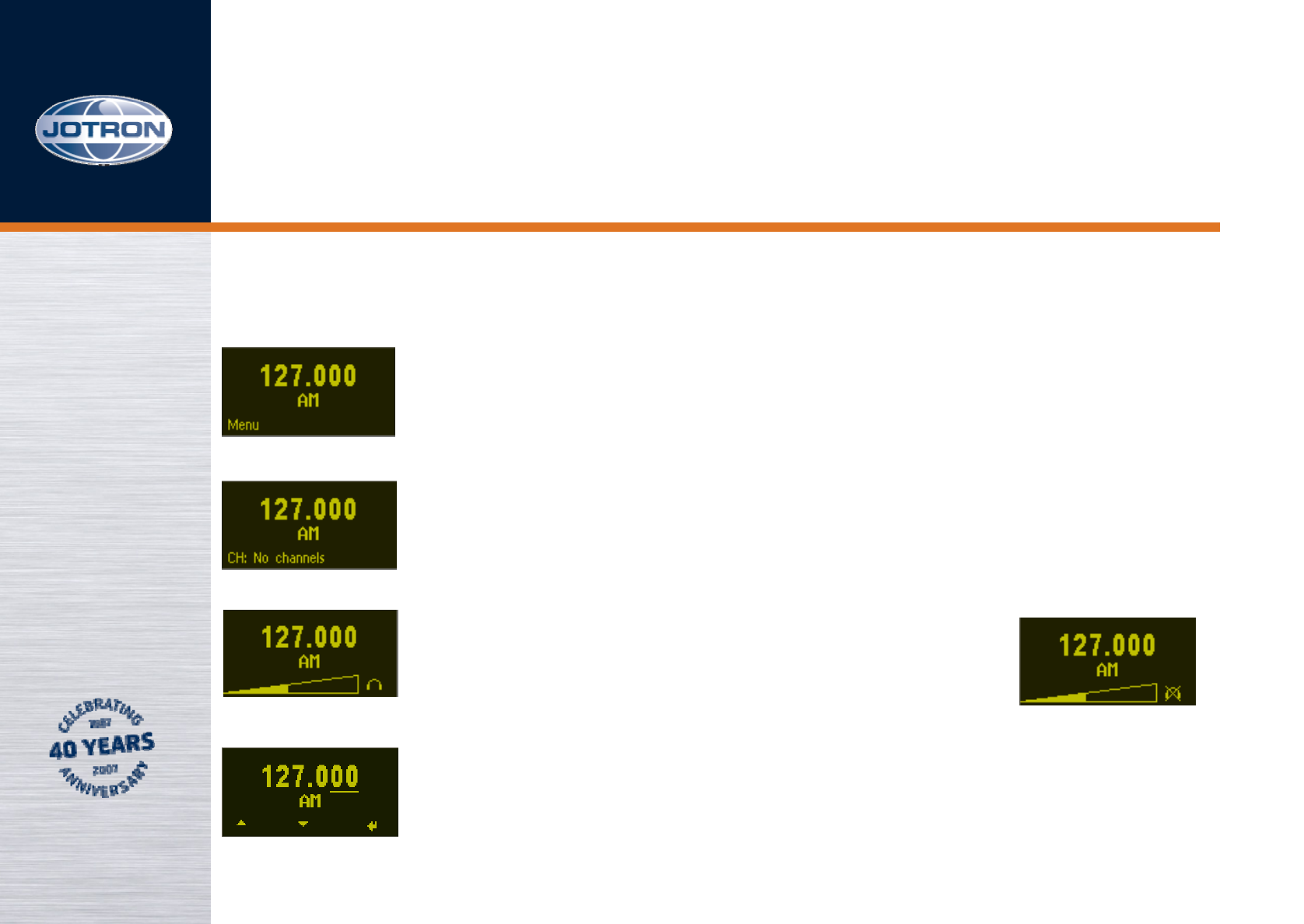
Normal operating display
Normal operating display with no channels
stored. Press FbC to recall stored channels.
Set headset volume by turning
RS. Press FbC to mute headset
See part 3 for selecting frequency
Press RS
TA-7625

Menus, 15 of 16
Operator menu, 2 of 3
Press RS
Press RS
Press FbC to store new frequency on specified
channel. Select storing channel by turning RS
Select brightness level by turning RS.
TA-7625

Menus, 16 of 16
Operator menu, 3 of 3
Press FbA
Press FbA
Press FbC
Select 8,33kHz steps by turning RS. For no changes
press FbC.
Select 100kHz steps by turning RS.
Select 1MHz steps by turning RS.
Press FbC to store new frequency and return.
TA-7625
Rear RJ45 connectors, 1 of 6
5
6
7
8
9
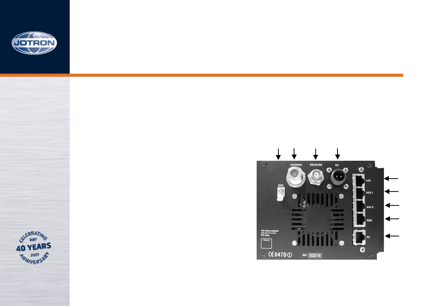
1 EARTH TAG
2 ANTENNA CONNECTOR
3 ANTENNA STANDBY / RX ANTENNA
OUTPUT CONNECTOR
4 DC INPUT CONNECTOR
5 LAN CONNECTOR
6 AUX 1 CONNECTOR
7 AUX 2 CONNECTOR
8 REMOTE CONNECTOR
9 RX CONNECTOR
TA-7625
1 2 3 4
Optional8LAN_D4N
Optional7LAN_D4P
Rx data6LAN_RXN
Optional5LAN_D3N
Optional4LAN_D3P
Rx data3LAN_RXP
Tx data2LAN_TXN
Tx data1LAN_TXP
PurposePINName
LAN interface connector
Rear RJ45 connectors, 2 of 6
TA-7625
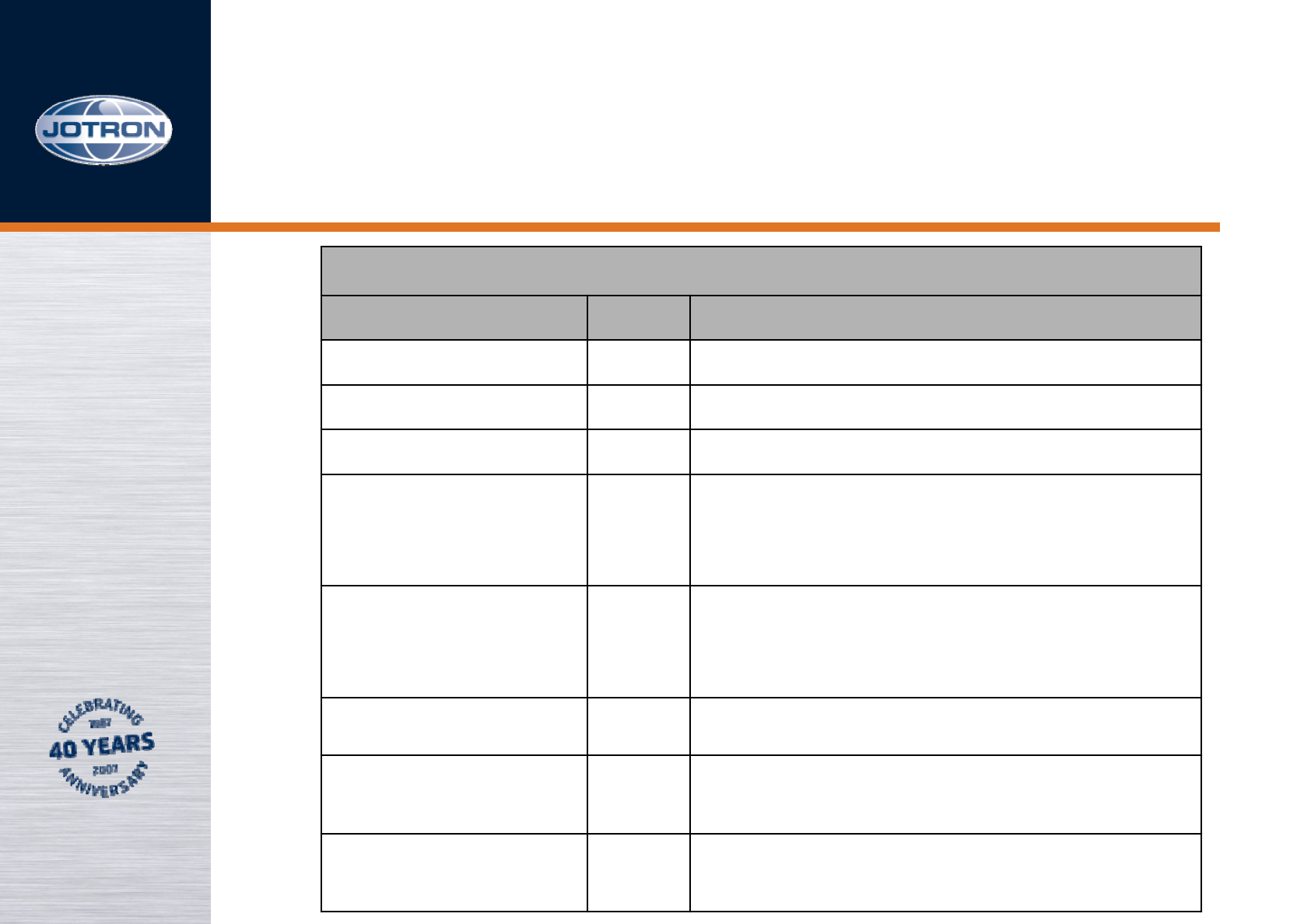
Aux 1 connector
Name PIN Purpose
ALARM_P 1Alarm out – rele
ALARM_N 2Alarm out – rele
Select_in_P 3Select in – opto isolated
RS232_S 4RS232 Transmit data
RS232_R 5RS232 Receive data
Select_in_N 6Select in – opto isolated
+12V 712V output to ext
equipment (D/O: 300mA)
GND 8Common ground
Rear RJ45 connectors, 3 of 6
TA-7625
AUX 2 connector
Name PIN Purpose
Key_out_P 1Closed=Transmitting - opto output
Key_out_N 2Closed=Transmitting - opto output
MONITOR_P 3Monitor output to tape recorder
TXLOW_P 4Applying a voltage > 5VDC between
pin 4 and 5 forces the transmitter into
low power
TXLOW_N 5Applying a voltage > 5VDC between
pin 4 and 5 forces the transmitter into
low power
MONITOR_N 6Monitor output to tape recorder
TXKEY_P 7Applying a voltage > 5VDC between
pin 7 and 8 will key the transmitter
TXKEY_N 8Applying a voltage > 5VDC between
pin 7 and 8 will key the transmitter
Rear RJ45 connectors, 4 of 6
TA-7625
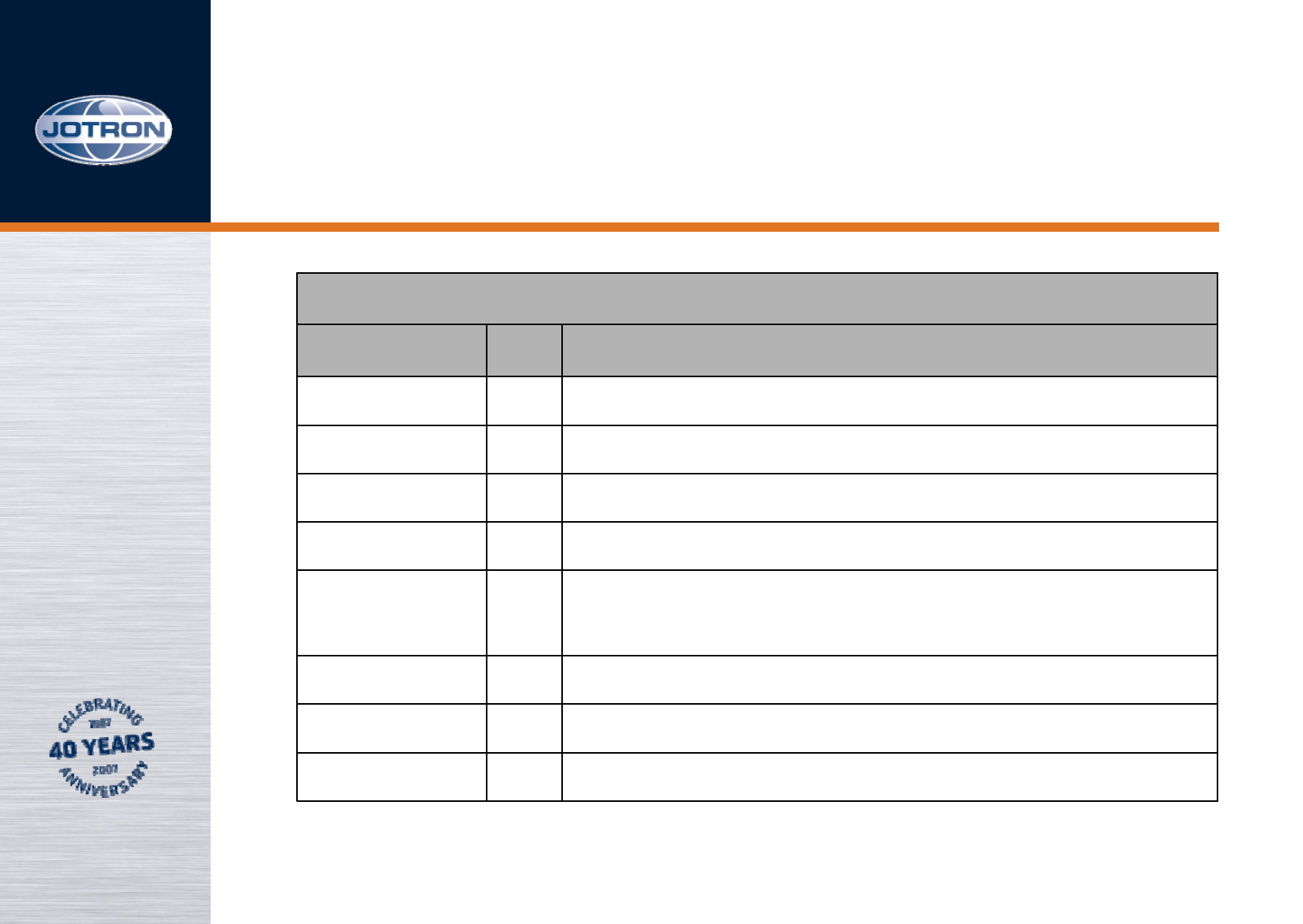
REM connector (Interface to remote equipment)
Name PIN Purpose
RS485_Z 1RS485 (-)
RS485_Y 2RS485(+)
LINE_P 3Diff. line input/output to TX/RX, 600 ohm
TX_KEY_G 4Key at GND
RX_BUSY_
OUT
5RX Busy indicator output (Squelch indicator)
LINE_N 6Diff. line input/output to TX/RX, 600 ohm
ALARM 7Low=Alarm (TX or TX/RX)
GND 8Common ground
Rear RJ45 connectors, 5 of 6
TA-7625
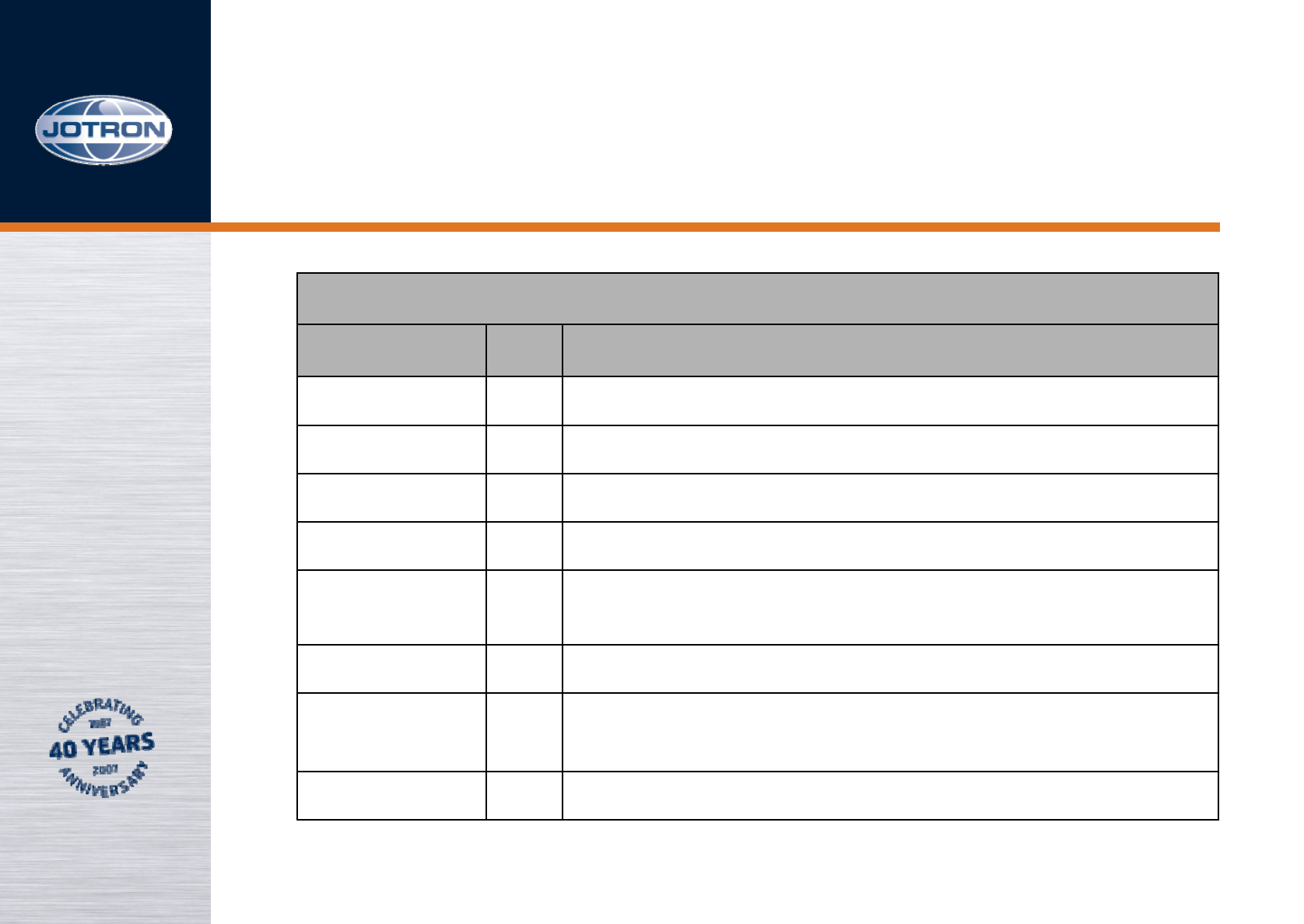
RX connector (Interface to receiver, transceiver config)
Name PIN Purpose
RS485_Z 1RS485 (-)
RS485_Y 2RS485(+)
LINE_P 3Diff. line input to RX, 600 ohm
TX_BUSY 4TX Busy indicator output (Mute output)
RX_BUSY 5RX Busy opto-input (Repeater Key input)
LINE_N 6Diff. line input to RX, 600 ohm
INT_ALARM 7Low=Alarm (Note: I/O – low input will also be
recognized as an alarm (EXT)
GND 8Common ground
Rear RJ45 connectors, 6 of 6
TA-7625
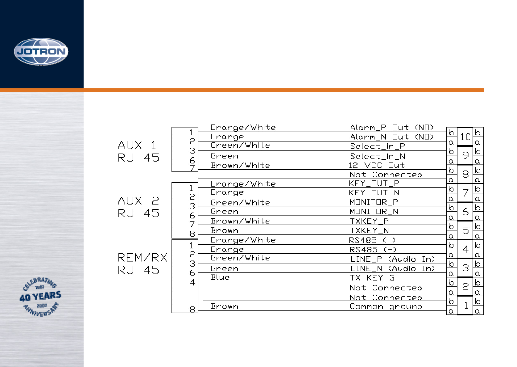
External wiring
RJ45 KRONE
TA-7625