Jotron AS TRON40SMKII 406 MHz EPIRB User Manual USE MAN 40SMkII vE
Jotron AS 406 MHz EPIRB USE MAN 40SMkII vE
UserManual.wiki
>
Jotron AS
>
TRON40SMKII User Manual
Users Manual
Navigation menu
Upload a User Manual
Namespaces
Wiki Guide
HTML
PDF
Info
Views
User Manual
Discussion / Help
Navigation
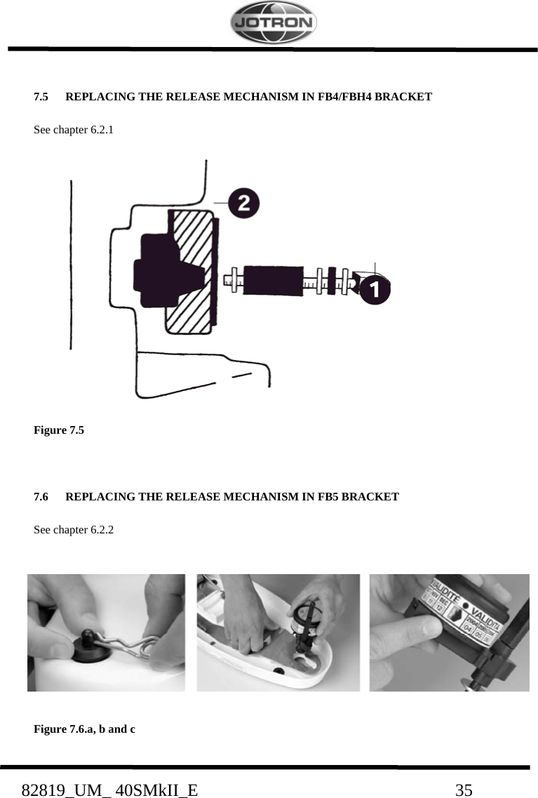
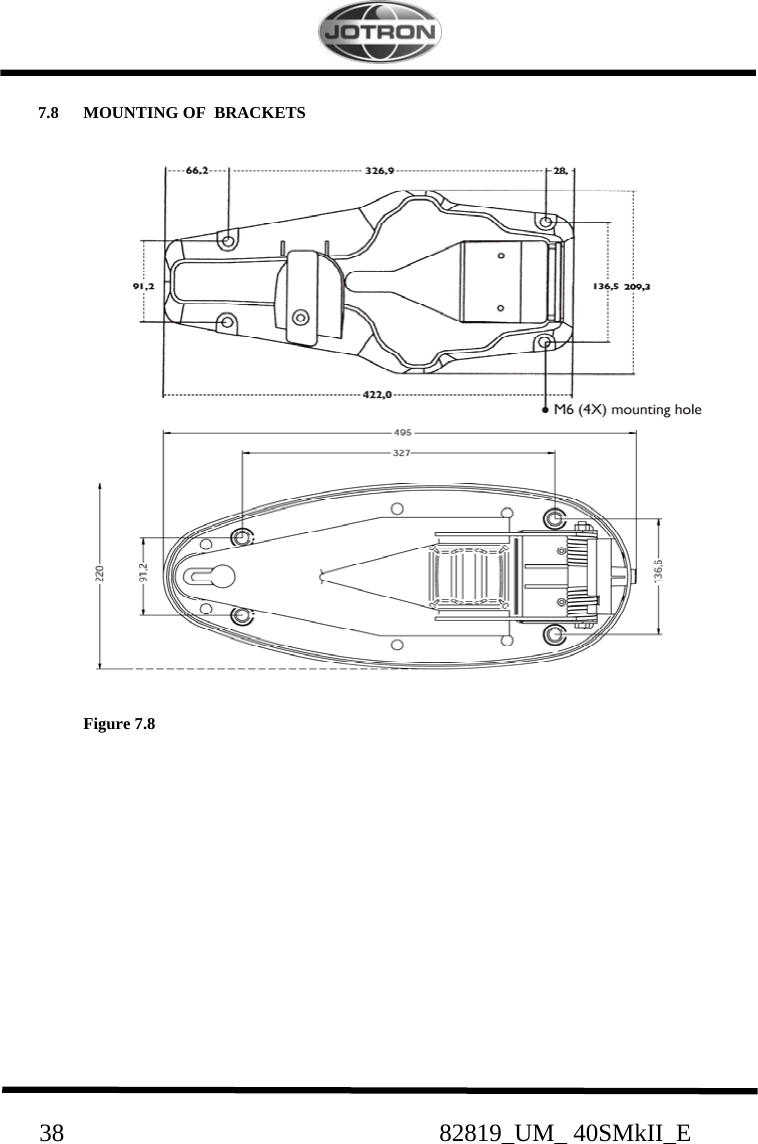
![82819_UM_ 40SMkII_E 29 6.1.5 LAND FILLING Leachability regulations (mg/l) Component Leachability EC limit EPA Other* Iron Nickel 100 100 500 2 5 0,5 * Applicable to France 6.1.6 RECYCLING Send to authorized recycling facilities, eventually through a licensed waste carrier. 6.2 HYDROSTATIC RELEASE REPLACEMENT For details see chapter 6.2.1 and 6.2.2. 6.2.1 REPLACING THE RELEASE MECHANISM IN FB4/FBH4 BRACKET See figure 7.5 The hydrostatic unit fitted on the float free bracket [FB4/FBH4] must be replaced every 2 years. Marking the expiry date on the hydrostatic unit. The hydrostatic comes complete with a new bolt and accessories. 1. Remove the EPIRB from its bracket by pulling out the locking pin on the clamp and open the retaining rod that holds the beacon. 2. Unscrew the plastic bolt (1) by screwing it counter clockwise and remove the hydrostatic release mechanism (2). 3. Check expiration date on the new hydrostatic release mechanism. The date should be approximately 2 years from the date of purchase. 4. Mount the new hydrostatic release mechanism. The unit is fixed to the bracket with a plastic bolt containing washer, rubber seal, washer, O-ring. 5. Secure the plastic bolt by hand force only!](https://usermanual.wiki/Jotron-AS/TRON40SMKII/User-Guide-925827-Page-29.png)