Jotron AS TRON40VDR Float Free EPIRB with VDR User Manual
Jotron AS Float Free EPIRB with VDR
Contents
- 1. Registration Form
- 2. User Manual
User Manual
USERS MANUAL
www.jotron.com
Tron 40VDR
Float Free Emergency Transmitter with VDR
2
www.jotron.com www.jotron.com
87634_UM_TRON_40VDR_A
MANUAL OPERATION AND ACTIVATION
It is not recommended to operate the beacon inside a life raft or under a cover
or canopy. Do NOT tie the lanyard to the ship in distress, as this will prevent the
unit to functioning if the ship sinks.
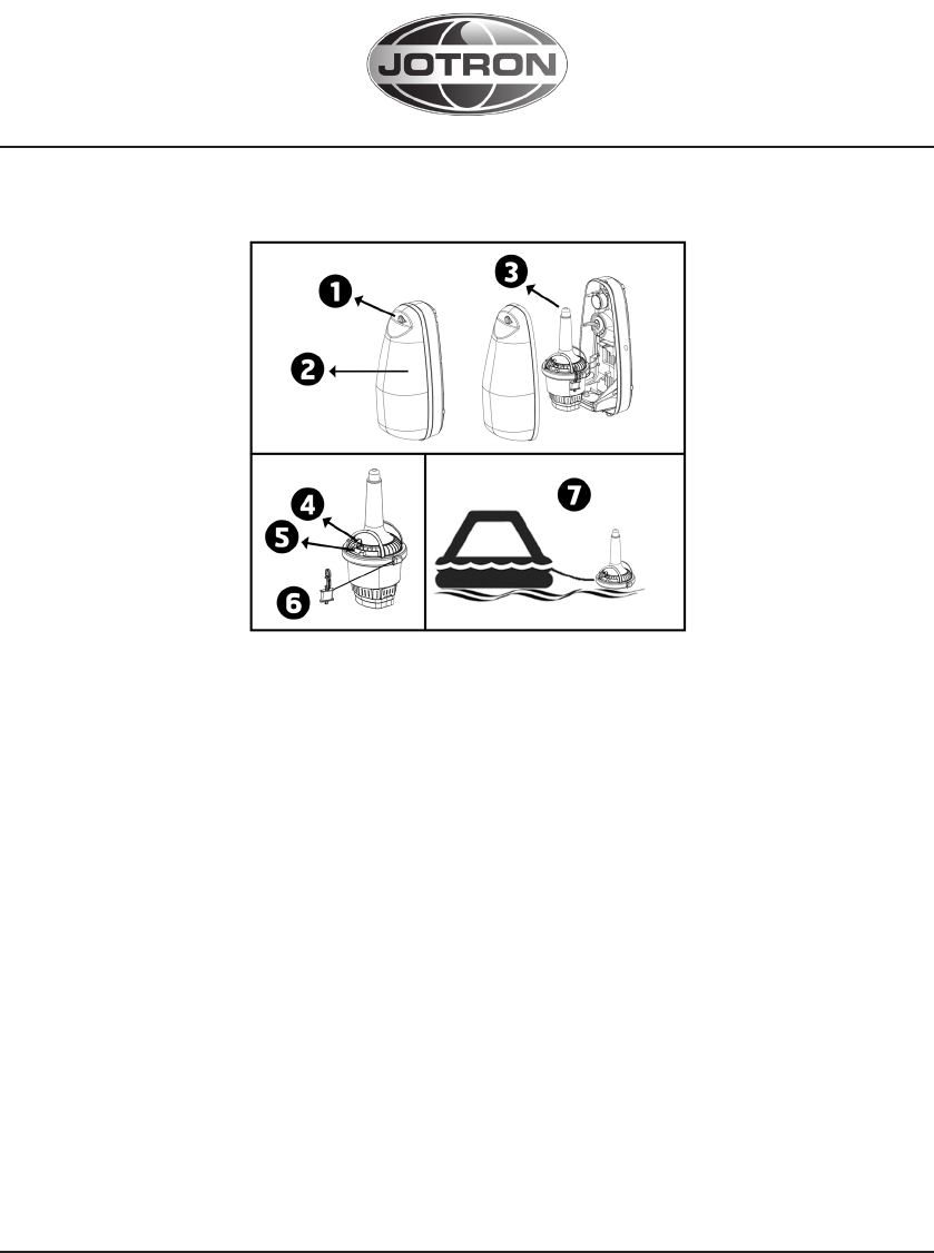
1. Remove the locking pin from bracket cover
2. Remove the cover
3. Take out the EPIRB from the bracket
4. Break the seal and pull the locking pin holding the main activator switch
5. Push slider to move switch to ON position (the switch is spring-loaded and will
automatically go to the ON position)
6. Tie the beacon lanyard to you or to the survival craft
7. The strobe light, located at the top of the EPIRB, will start flashing indicating
that the EPIRB is operating
If possible keep the EPIRB in an open area, away from any metal objects (ship
construction etc.) that may limit the satellite coverage. Transmission can be
stopped by turning the switch to READY position and take it out of the water.
EC Declaration of Conformity, available at www.jotron.com

3
www.jotron.com www.jotron.com
87634_UM_TRON_40VDR_A
IMPORTANT
The information in this book has been carefully checked and is believed to be
accurate. However, no responsibility is assumed for inaccuracies.
This equipment contains CMOS integrated circuits. Observe handling precau-
tions to avoid static discharges which may damage these devices. Jotron AS
reserves the right to make changes without further notice to any products or
modules described herein to improve reliability, function or design. Jotron AS
does not assume any liability arising out of the application or use of the de-
scribed product.
WARNING / IMPORTANT
Jotron AS is a prime manufacturer of safety equipment designed for rescue of
human lives and their property. For safety equipment to be effective in line with
the design parameters it is important that they are handled, stowed and main-
tained in compliance with the manufacturers instructions. Jotron AS can not be
held responsible for any damage caused due to incorrect use of the equipment
or breach of laid down procedures or for failure of any specific component or
other parts of the equipment.
The chapter covering battery replacement is added for information only. Jotron
AS does not take any responsibility for improper disassembling/assembling of
the beacon. We strongly recommend all service to be done by authorized Jotron
AS agents. In addition to normal service, Jotron AS agents have the necessary
equipment and education to test the operational functions of the beacon. Non-
original maintenance and/or service parts may destroy the equipment function
and performance.

4
www.jotron.com www.jotron.com
87634_UM_TRON_40VDR_A
WARRANTY AND LIMITATION.
This product is warranted against factory defects in material and workmanship
for a period of 5 years from date of purchase. During the warranty period Jotron
AS will repair or, at its option, replace the unit at no cost to you for labour, ma-
terials and return transportation from Jotron AS or its subsidiaries.
For further assistance, please contact repair@jotron.com
This warranty does not apply if the product has been damaged by ac-
cident or misuse, or as a result of service or modification performed by
an unauthorized factory or person. The Company shall not be liable for
consequential or special damages.
COUNTERFEIT SPARE PARTS.
Jotron AS is aware of extended counterfeit spare parts being marketed and sold
to fit GMDSS safety products. It is of extreme importance that any spare parts
being fitted to this product are original spare parts, manufactured or approved
by Jotron AS. Any use of counterfeit spare parts will deviate from the product
type-approval certificates.
PRODUCT RECYCLING AND DISPOSAL
Tron 40VDR Float Free Capsule can be recycled according to EC Directive
WEEE, except for the battery-module. The battery-module consists of Lithium
batteries and must be handled acc to local regulations concerning primary
Lithium battery guidance.
5
www.jotron.com www.jotron.com
87634_UM_TRON_40VDR_A

6
www.jotron.com www.jotron.com
87634_UM_TRON_40VDR_A
INNHOLD
1 GENERAL DESCRIPTION 8
1.1 TRON 40VDR 8
1.2 SYSTEM DESCRIPTION 9
1.2.1 SIGNAL DETECTION 9
1.2.2 DISTRESS LOCATION DETERMINATION 10
1.2.3 GPS ADVANTAGE 10
1.2.4 EPIRB REGISTRATION 11
2 TECHNICAL SPECIFICATIONS 14
2.1 GENERAL 14
2.2 COSPAS-SARSAT TRANSMITTER 14
2.3 NAVIGATION DEVICE 14
2.4 HOMING TRANSMITTER 15
2.5 BRACKETS 15
2.6 BATTERY SAFETY DATA SHEET 15
2.6.1 HAZARDS IDENTIFICATION 15
2.6.2 FIRST AID MEASURES 16
2.6.3 FIRE FIGHTING MEASURES 16
2.6.4 HANDLING AND STORAGE 17
3 EPIRB DESCRIPTION 18
3.1 GENERAL 18
3.2 BATTERY MODULE 19
3.3 FLOAT FREE BRACKET 19
4 INSTALLATION OF TRON 40VDR FLOAT FREE CAPSULE 20
4.1 FB-40 BRACKET INSTALLATION AND MOUNTING 20
4.2 HOW TO FIT TRON 40VDR CAPSULE IN THE BRACKET 21
5 OPERATION INSTRUCTIONS 22
5.1 MANUAL OPERATION 22
5.1.1 OUT OF BRACKET 23
5.1.2 IN THE FLOAT FREE BRACKET FB-40 23
5.2 AUTOMATIC OPERATION - FLOAT FREE BRACKET FB-40 24
6 TESTING AND PERIODICAL CONTROL 25
6.1 TESTING 25
6.1.1 NORMAL SELF-TEST 25
6.1.2 EXTENDED SELF-TEST INCLUDING GPS-TEST 25
6.1.3 EPIRB ERROR MESSAGES 26
6.2 PERIODICAL CONTROL 27
7
www.jotron.com www.jotron.com
87634_UM_TRON_40VDR_A
6.2.1 EVERY MONTH: 27
6.2.2 EVERY 12TH MONTH: 27
6.2.3 EVERY 2ND YEAR: 28
6.2.4 EVERY 4th OR 5th YEAR: 28
6.2.5 EVERY 10th YEAR: 28
6.3 TEST AND MAINTENANCE RECORD 28
6.4 FALSE ALERT 29
6.5 SERVICE PROCEDURE 30
6.5.1 WARRANTY CLAIM 30
6.5.2 SERVICE – NOT WARRANTY CLAIM 30
7 MAINTENANCE 31
7.1 EPIRB MODULE / BATTERY PACK 31
7.1.1 CHANGE OF BATTERY 31
7.2 HYDROSTATIC RELEASE REPLACEMENT 32
7.2.1 REPLACING THE RELEASE MECHANISM IN FB-40
BRACKET 32
8 SPARE PARTS 34
8.1 Tron 40VDR SPARE PARTS 34
8.2 COUNTERFEIT SPARE PARTS. 34
9 SERVICE AGENTS 35
10 ABBREVIATIONS AND DEFINITIONS 36
11 AMENDMENT RECORDS 38

8
www.jotron.com www.jotron.com
87634_UM_TRON_40VDR_A
1 GENERAL DESCRIPTION
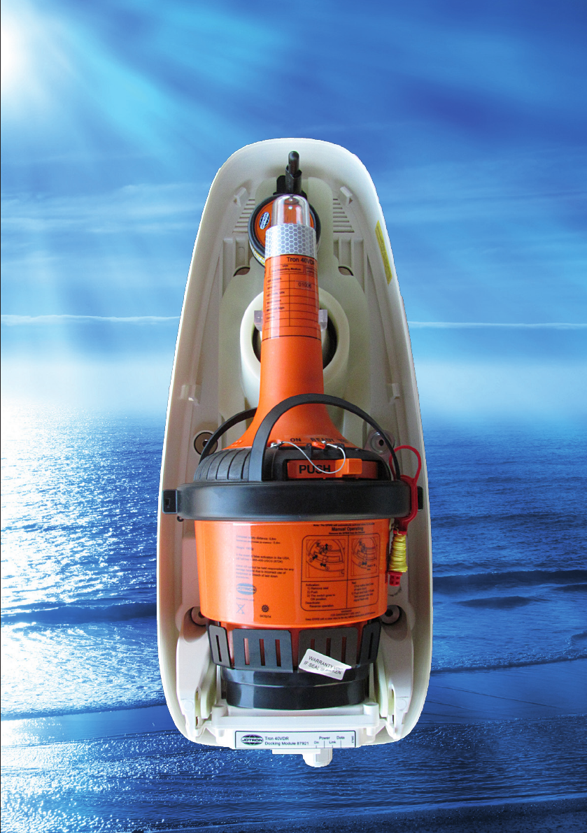
The Tron 40VDR is emergency equipment consisting of:
• Tron 40VDR Cospas-Sarsat emergency EPIRB.
• FB-40 - Automatic float free bracket.
• VDR storage module.
The Tron 40VDR EPIRB is developed to meet the regulations and rules for use
on vessels and life rafts in the maritime service. Tron 40VDR meets the following
specifications for 406 MHz EPIRBs for use in search and rescue operations at
sea.
See “Declaration of Conformity” document at www.Jotron.com for information
of required standards.
1.1 TRON 40VDR
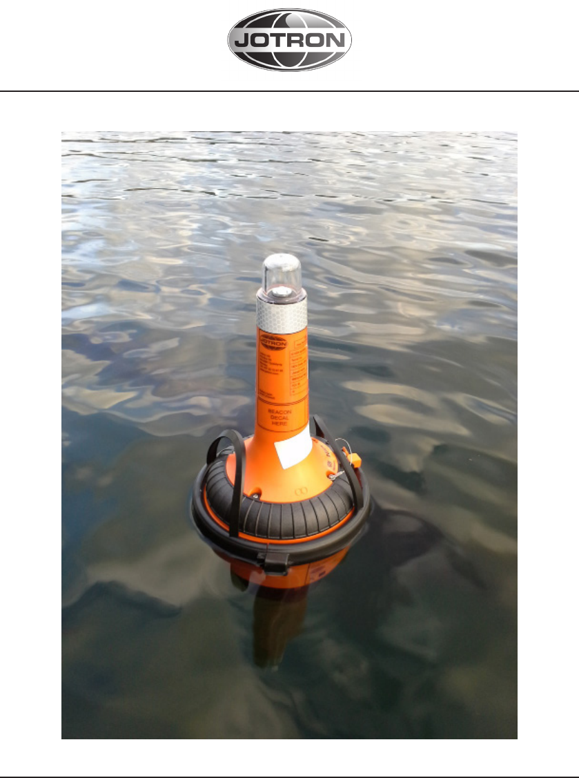
The Tron 40VDR is buoyant and have water activated contacts which will start
DISTRESS transmission if deployed into water. Tron 40VDR are currently avail-
able with one float free bracket. The bracket prevents DISTRESS transmission if
water spray are applied to the EPIRB.
The Float free bracket, FB-40 is a covered bracket with an hydrostatic release
unit (HRU) which will release the Tron 40VDR if the bracket is submerged to a
depth of 2-4 meters if the ship are about to sink.
The purpose of the Tron 40VDR is to give a primary alarm to the search and
rescue authorities. The EPIRB gives an immediate alarm when activated, trans-
mitting the ID of the ship in distress. Care must be taken not to activate the
EPIRB unless in an emergency situation, in such cases the user will be held re-
sponsible. For periodic testing a test function is implemented. During the test
cycle the EPIRB does a self-test on the transmitters and on the battery status.
No emergency signal is transmitted during the self-test.
The battery of the EPIRB will last for at least 168 hours from activation of the
EPIRB.
9
www.jotron.com www.jotron.com
87634_UM_TRON_40VDR_A
1.2 SYSTEM DESCRIPTION
The Cospas-Sarsat system was introduced in 1982 as a worldwide search and
rescue system with the help of satellites covering the earth’s surface. Since the
introduction of the system more than 28000 persons have been rescued by
the Cospas-Sarsat system (2009). Currently the system consists of 5 functional
satellites in a polar orbit constellation, these satellites cover the entire earth’s
surface and receive the emergency signal from the 406 MHz transmitter within
the Tron 40VDR, more polar orbiting satellites will be available in the future, giv-
ing a faster location and rescue time.
In addition several geostationary satellites are equipped with a 406 MHz tran-
sponder, these satellites are not able to locate the Tron 40VDR but will give an
early warning to the rescue forces, minimising the time from an emergency oc-
curs till the rescue forces are at the site.
Each emergency EPIRB in the system is programmed with its own unique code,
therefore it is vital that the ships data that is given to the dealer you obtained
your Tron 40VDR, is correct. It is also important that your EPIRB is registered in
the database for each country. This database is normally located in the same
country that the ship is registered.
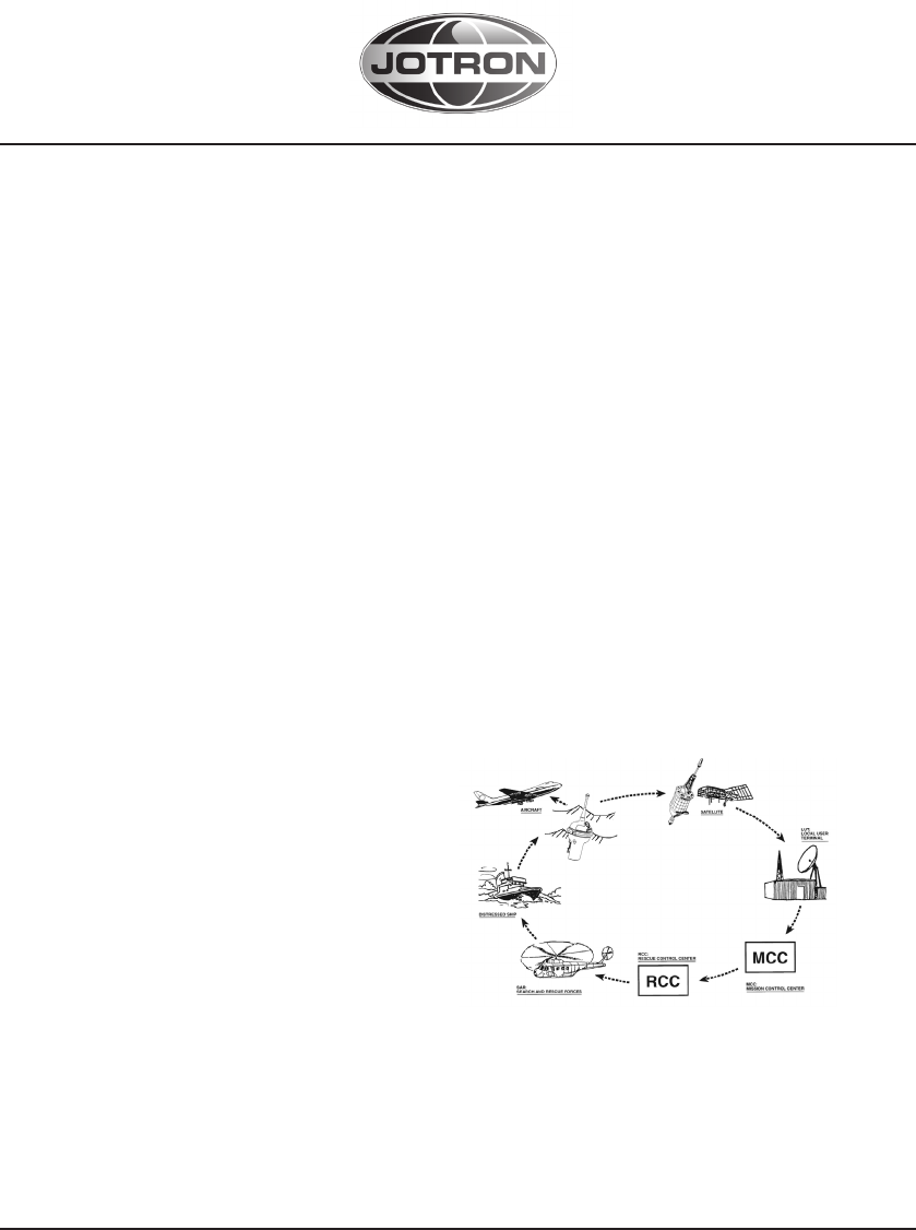
1.2.1 SIGNAL DETECTION
When the Tron 40VDR is activated
(manually or automatically) it trans-
mits on the frequencies 121.5 MHz and
406.037 MHz. An analogue signal is
emitted on 121.5 MHz and a digital
signal is transmitted on 406.037 MHz.
After the Tron 40VDR is activated, the
next passing satellite will detect the transmitted signal and relay it to an an-
tenna at a ground station, called LUT.
The International Cospas-Sarsat System has ceased satellite processing of
121.5/243 MHz beacons from 1 February 2009.
10
www.jotron.com www.jotron.com
87634_UM_TRON_40VDR_A
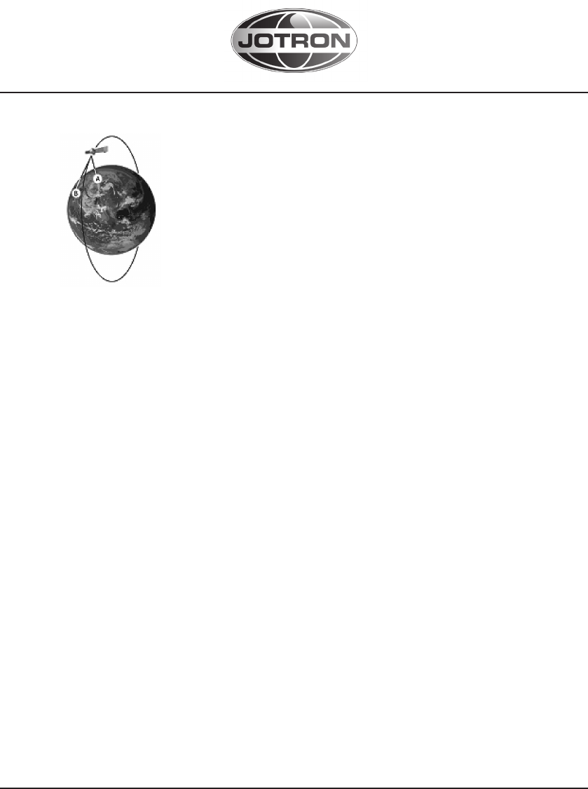
1.2.2 DISTRESS LOCATION DETERMINATION
The location of the distress signal is determined by taking
measurements of the doppler shift of the EPIRB frequency
when the satellite first approach and then pass the EPIRB.
The actual frequency is heard at the time of closest approach
(TCA). Knowing the position of the satellite and using the re-
ceived doppler signal information, it is possible to determine
the location of the Tron 40VDR from the satellite at the TCA.
At the LUT, actually two positions are calculated. One is the actual position (A)
and the other is the mirror image (B) position. A second satellite pass confirms
the correct location (A). Doppler-only accuracy is within 5 km (3 mi) (3.1 statute
miles or 2.6 nautical miles)— that is, the position is sufficiently accurate for SAR
purposes even after only one pass. What’s more, the most likely of the two ’mir-
ror’ positions can be determined valid with 98.5% accuracy after only one satel-
lite pass. This accuracy can be increased to 99.3% using so-called ”combined
Leo-Geo processing,” and this technique also enables accurate positions to be
generated with as little as two or three bursts from the beacon (i.e. less than 4
minutes of transmission) and thus greatly increases the chances of being found
even if the beacon is ultimately consumed by fire or is otherwise destroyed
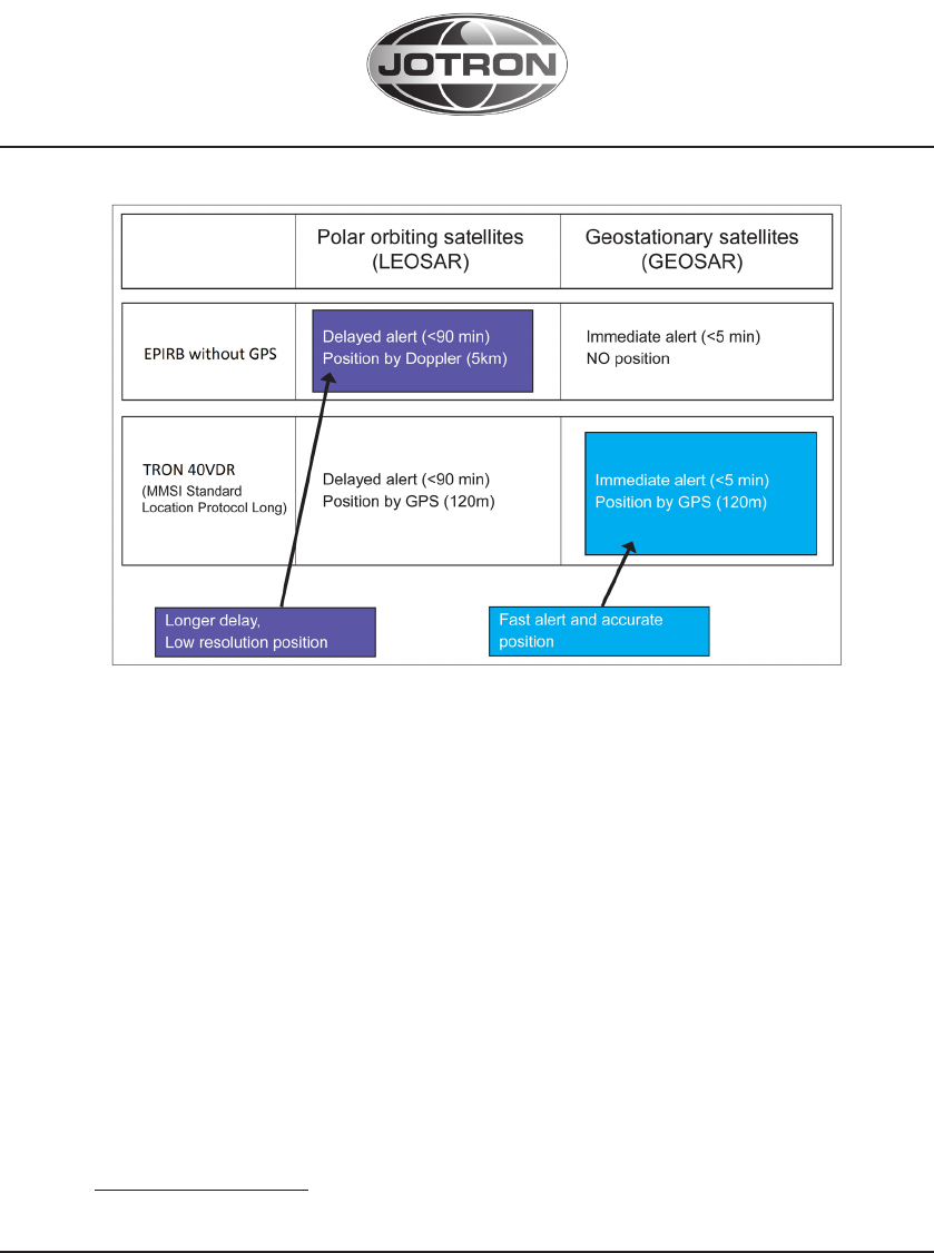
1.2.3 GPS ADVANTAGE
Tron 40VDR has been designed to operate with the Cospas-Sarsat system and
will enhance further the lifesaving capabilities of conventional beacons.
Please see picture on next page for comparison between Tron 40VDR and
EPIRB without GPS depending on detection by polar orbiting or geostationary
satellites.
GPS position is updated every 6-16 minutes, and can also be tested in SELF-
TEST.
11
www.jotron.com www.jotron.com
87634_UM_TRON_40VDR_A
1.2.4 EPIRB REGISTRATION
Normally the MCC will contact the vessel or the contact person registered in a
shipping register and/or an EPIRB register (Ships owner, family member etc.) be-
fore alerting the RCC. This is to determine if the alarm from the EPIRB for some
reason is a false alarm, and an expensive rescue operation can be avoided. Be-
cause of this it is important that the ships data is correct in the shipping register
or in the EPIRB database.
You should register your beacon with the national authority associated with the
country code in the hexadecimal identification (15 Hex ID) of your beacon. You
can register your beacon online with the Cospas-Sarsat IBRD if your country
does not provide a registration facility and your country has allowed direct reg-
istration in the IBRD: www.406registration.com
If your country operates a national beacon registry, consult the document
C/S S.007 ”Cospas-Sarsat Handbook of Beacon Regulations” available at
www.cospas-sarsat.org to obtain the point of contact.

12
www.jotron.com www.jotron.com
87634_UM_TRON_40VDR_A
Some EPIRB registration links:
USA: http://www.beaconregistration.noaa.gov
UK: http://www.mcga.gov.uk (search for ”EPIRB registration”)
USA REGISTRATION CARD
For registration of the beacon, use this link:
http://www.beaconregistration.noaa.gov
Follow instructions you see on your screen.
Other registrations methods are mail or fax. Forms are ready with correct infor-
mation and it may be downloaded from the above web site.
The Emergency Contact information has to be accurate, especially regarding
the telephone number, as this will be used to validate an alert. Only if the bea-
con registration and approximate location details can be confirmed will USCG
(United States Coast Guard) launch an immediate rescue, otherwise there will be
a delay whilst further alerts from the same source are received and verified.
Registration address:
SARSAT BEACON REGISTRATION
NOAA
NSOF, E/SPO53
1315 East West Hwy
Silver Spring, MD 20910
13
www.jotron.com www.jotron.com
87634_UM_TRON_40VDR_A

14
www.jotron.com www.jotron.com
87634_UM_TRON_40VDR_A
2 TECHNICAL SPECIFICATIONS
2.1 GENERAL
Battery: Primary Lithium-Thionyl Chloride, 7.2V/ 18Ah,
5 years service life
Housing material: Glass reinforced Polycarbonate
Dimensions:
• Weight: 1.9 kg
• Height: 400 mm
• Max diameter: 200 mm
Compass safe distance: 0,8 m
Temperature operating: -20°C to + 55°C (-4°F to +131°F)
Temperature storage: -40°C to + 65°C (-22°F to +149°F)
Operating life: Minimum 168 hours at -20°C
2.2 COSPAS-SARSAT TRANSMITTER
Frequency: 406.037 MHz 2 ppm
Output power: 5W 2 dB
Protocols: Tron 40VDR: Maritime, Serialized, Radio Call sign,
Location protocols
Modulation: Phase modulation 1.1 0.1 rad
Data encoding: Bi Phase L
Stability: Short term: 2 x10e-9
Medium term: 0e-9
Residual noise: 3 x10e-9
Bit rate: 400 b/s
Antenna: Built in, omnidirectional
2.3 NAVIGATION DEVICE
Type: 22 Channel GPS Receiver
Antenna: Chip type
+
-
-
+
+
-
>
>
>
_
_
_
15
www.jotron.com www.jotron.com
87634_UM_TRON_40VDR_A
2.4 HOMING TRANSMITTER
Frequency: 121.500 MHz
Output power: Up to 100 mW
Modulation: A9, AM sweep tone between 300Hz and 1600Hz
Sweep range: 700 Hz
Sweep rate: 2.5 Hz
Stability: 10 ppm over temperature range
Antenna: Built in, omnidirectional
2.5 BRACKETS
Materials: Glass reinforced polycarbonate / Glass reinforced
nylon
Dimensions (H/L/W): 215mm / 553mm / 236mm
Weight: 2.9 Kg
Release mechanism: Jotron HRU kit (part. no. 86218)
2.6 BATTERY SAFETY DATA SHEET
PRODUCT NAME: SAFT BATTERIES
TYPE NO.: LSH 14 LIGHT
LITHIUM METAL CONTENT: BELOW 1g/CELL
APPROXIMATE WEIGHT: 51g
CHEMICAL SYSTEM: Primary lithium-thionyl chloride (Li-SOCI2)
DESIGNED FOR RECHARGE: No
2.6.1 HAZARDS IDENTIFICATION
Do not short circuit, recharge, puncture, incinerate, crush, immerse, force dis-
charge or expose to temperatures above the declared operating temperature
range of the product. Risk of fire or explosion. The Lithium-Thionyl chloride bat-
teries described in this Safety Data Sheet are sealed units which are not hazard-
ous when used ac- cording to the recommendations of the manufacturer

16
www.jotron.com www.jotron.com
87634_UM_TRON_40VDR_A
Under normal conditions of use, the battery is hermetically sealed.
Ingestion: Swallowing a battery can be harmful.
Inhalation: Contents of an open battery can cause respiratory irrita
tion.
Skin Contact: Contents of an open battery can cause skin irritation.
Eye Contact: Contents of an open battery can cause severe irritation.
2.6.2 FIRST AID MEASURES
Ingestion: Do not induce vomiting or give food or drink. Seek medical
attention immediately. CALL NATIONAL BATTERY
INGESTION HOTLINE for advice and follow-up (202-625-
3333) collect day or night.
Inhalation: Provide fresh air and seek medical attention.
Skin Contact: Remove contaminated clothing and wash skin with soap
and water.
Eye Contact: Immediately flush eyes thoroughly with water for at least 15
minutes, lifting upper and lower lids, until no evidence of the
chemical remains. Seek medical attention.
Note: Carbon black is listed as a possible carcinogen by International Agency
for Research on Cancer (IARC).
2.6.3 FIRE FIGHTING MEASURES
In case of fire where lithium batteries are present, flood area with water or
smother with a Class D fire extinguishant appropriate for lithium metal, such as
Lith-X. Water may not extinguish burning batteries but will cool the adjacent
batteries and control the spread of fire. Burning batteries will burn themselves
out. Virtually all fires involving lithium batteries can be controlled by flooding
with water. However, the contents of the battery will react with water and form
hydrogen gas. In a confined space, hydrogen gas can form an explosive mixture.
In this situation, smothering agents are recommended. A smothering agent will
extinguish burning lithium batteries.
Emergency Responders should wear self-contained breathing apparatus. Burn-
ing lithium-iron disulfide batteries produce toxic and corrosive lithium hydroxide
fumes and sulfur dioxide gas.

17
www.jotron.com www.jotron.com
87634_UM_TRON_40VDR_A
2.6.4 HANDLING AND STORAGE
Storage: Store in a cool, well ventilated area. Elevated temperatures can result
in shortened battery life. In locations that handle large quantities of lithium bat-
teries, such as warehouses, lithium batteries should be isolated from unneces-
sary combustibles.
- WARNING:
Battery can explode or leak and cause burns if installed backwards, disassem-
bled, charged, or exposed to water, fire or high temperature.
18
www.jotron.com www.jotron.com
87634_UM_TRON_40VDR_A
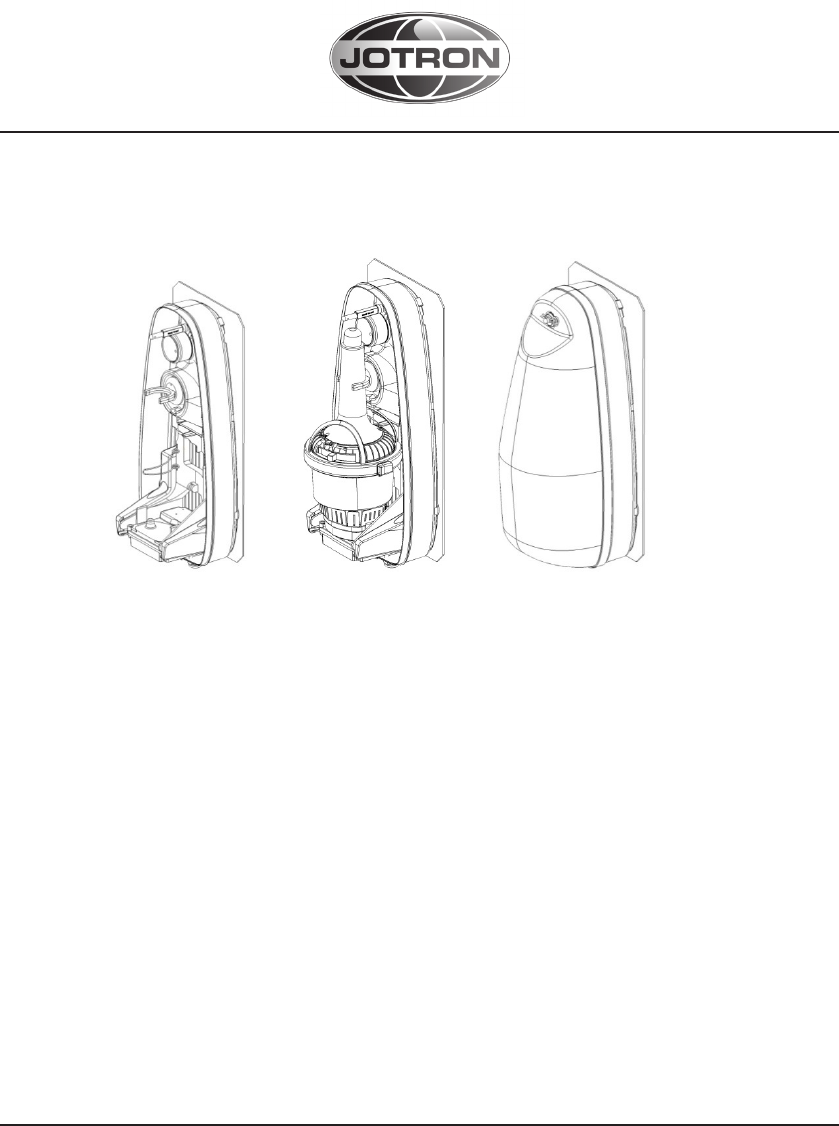
3 EPIRB DESCRIPTION
3.1 GENERAL
Tron 40VDR Float Free Capsule consists of upper and lower house mounted
together with an equator ring. On the lower housing, the VDR storage module is
fitted as a removable module, connected to the EPIRB through a clamp.
The EPIRB may be split into the following main parts when disposal:
1. EPIRB module with antenna
2. Equator ring and Gasket.
3. Battery-module.
4. VDR storage module.
5. VDR storage module sealing bracket.
19
www.jotron.com www.jotron.com
87634_UM_TRON_40VDR_A
3 EPIRB DESCRIPTION
3.1 GENERAL
Tron 40VDR Float Free Capsule consists of upper and lower house mounted
together with an equator ring. On the lower housing, the VDR storage module is
fitted as a removable module, connected to the EPIRB through a clamp.
The EPIRB may be split into the following main parts when disposal:
1. EPIRB module with antenna
2. Equator ring and Gasket.
3. Battery-module.
4. VDR storage module.
5. VDR storage module sealing bracket.
3.2 BATTERY MODULE
The Battery module supplies the EPIRB module with power to keep the EPIRB
transmitters active for 168 hours when activated, and for test sequences. The
water detector is mounted in the battery module and can be seen as two metal
contacts on the back of the battery housing. Pay attention not to touch both
contacts while carying Tron 40VDR as this can be detected as water and acti-
vate the EPIRB.
3.3 FLOAT FREE BRACKET
The Float Free bracket, type FB-40, is an automatic bracket, were a hydrostatic
release mechanism (HRU) releases the EPIRB from the bracket when reaching
2-5 mtr below sea-level.
The HRU is type approved by Jotron and special adjusted to the FB40 includes a
special bolt with adjusted fittings. This module is supplied as a HRU-Kit.
The Tron 40VDR Float Free Capsule is activated automatically when immersed
into water. There is a safety switch which prevents the water sensors from acti-
vating the beacon while placed in the mounting bracket.
20
www.jotron.com www.jotron.com
87634_UM_TRON_40VDR_A
4 INSTALLATION OF TRON 40VDR FLOAT FREE CAPSULE
WARNING:
DO NOT INSTALL THE EPIRB NEAR STRONG
MAGNETIC FIELDS THAT COULD ACTIVATE THE BEACON
4.1 FB-40 BRACKET INSTALLATION AND MOUNTING
The Tron 40VDR Float Free Capsule should be installed in a location guid-
ed by COMSAR.Circ 32 (Chap 4.10)
http://www.imo.org/blast/blastDataHelper.asp?data_id=10750&lename=32.
pdf
Installation of the FB-40 bracket can be made direct on the ship-wall, as
long as the contact of the surface is plane and the areas is bigger than
the actual bracket. The FB-40 needs rm ground contact on the grounding
screw. Please ensure as short and wide grounding path as possible. Apply
silicone grease on the screw before mounting to ensure good connection.
21
www.jotron.com www.jotron.com
87634_UM_TRON_40VDR_A
4.2 HOW TO FIT TRON 40VDR CAPSULE IN THE BRACKET
Make sure the FB-40 bracket is mounted correct on the rail and/or the
ship-wall.Take the Tron 40VDR Float-Free Capsule and match the lower
part correct on the dock-module and easy press/lay the unit safely in the
stability-bracket. Mount the top-cover correct by tting the lower-end rst
and then make sure the HRU (Hydro Static Release)-bolt is secured by the
spacer and splint-pin. Pay attention to the notch on the cover. If the cover
does not t then it may help to compress it carefully on the sides. See illus-
tration.
22
www.jotron.com www.jotron.com
87634_UM_TRON_40VDR_A
5 OPERATION INSTRUCTIONS
WARNING
• USE ONLY DURING SITUATIONS OF GRAVE AND IMMINENT DANGER
• REPLACE THE BATTERY AFTER THE SATELLITE EPIRB IS OPERATED FOR
ANY PURPOSE OTHER THAN A TEST
Tron 40VDR is designed to be operated either manually or automatically.
The EPIRB is always armed when located in the bracket. The EPIRB will automati-
cally start to transmit when removed or ejected from the bracket and deployed
into water. The EPIRB has an internal safety switch which prevents inadvertent
activation through moisture, sea spray etc when located in the bracket.
5.1 MANUAL OPERATION

23
www.jotron.com www.jotron.com
87634_UM_TRON_40VDR_A
5.1.1 OUT OF BRACKET
For operation of the beacon out of the bracket follow instructions from 4-5 in
chapter 5.1.2
5.1.2 IN THE FLOAT FREE BRACKET FB-40
For operation of the beacon in the bracket please follow instructions 1 to 7.
It is not recommended to operate the beacon inside a life raft or under a cover
or canopy. Do NOT tie the lanyard to the ship in distress, as this will prevent the
unit to functioning if the ship sinks.
1. Remove the cotter pin from the bracket (FB-40)
2. Remove the FB-40 cover
3. Take out the EPIRB from the bracket
4. Pull the locking pin holding the main switch.
5. Push and move main switch to the left, to ON position. The LED indicator,
located at the top of the antenna, will start to flash, indicating that the
EPIRB is operating.
6. Tie the beacon lanyard to you or to the survival craft
7. If possible keep the EPIRB in an open area, away from any metal objects
(ship construction etc.) that may limit the satellite coverage. This is
especially important for Tron 40VDR, since it needs good reception to
obtain a GPS position.
NOTE: To stop transmission, take Tron 40VDR out of the water and move
the main switch to READY position.
24
www.jotron.com www.jotron.com
87634_UM_TRON_40VDR_A
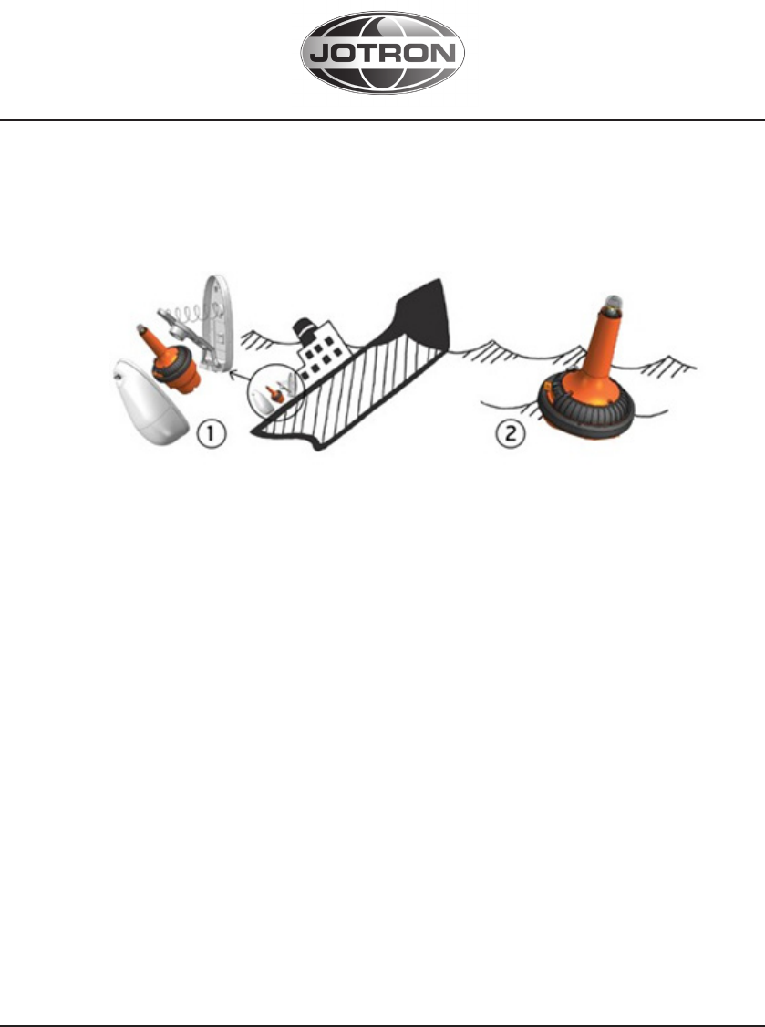
5.2 AUTOMATIC OPERATION - FLOAT FREE BRACKET FB-40
1. The Tron 40VDR will automatically release from the bracket, float to the
surface and start to transmit when the EPIRB, in its bracket is deployed into
water at a depth of app. 2-4 meters (6 - 13 feet).
2.Transmission will continue until the EPIRB is lifted out of the water, and dried
off. The transmission can also be stopped by placing the EPIRB in the bracket.

25
www.jotron.com www.jotron.com
87634_UM_TRON_40VDR_A
5.2 AUTOMATIC OPERATION - FLOAT FREE BRACKET FB-40
1. The Tron 40VDR will automatically release from the bracket, float to the
surface and start to transmit when the EPIRB, in its bracket is deployed into
water at a depth of app. 2-4 meters (6 - 13 feet).
2.Transmission will continue until the EPIRB is lifted out of the water, and dried
off. The transmission can also be stopped by placing the EPIRB in the bracket.
6 TESTING AND PERIODICAL CONTROL
6.1 TESTING
There are two different kinds of tests that can be performed:
1. Normal self-test
2. Extended self-test including the GPS.
Jotron AS recommends the Tron 40VDR Float Free Capsule to be tested
every month. This test involves both the self-test and GPS-test. Note: The
extended self-test are imitated to 60 for a period of 5-year.
6.1.1 NORMAL SELF-TEST
To perform the self-test, the EPIRB has to be removed from the FB-40 bracket.
1. Release FB-40 top cover by removing the cotter pin.
2. Take Tron 40VDR out of the bracket.
3. Push and hold switch in TEST position for 15 seconds. Keep hands and other
objects away from the antenna.
4. Test passed after one single flash only!
5. Release the switch and put the EPIRB back into the bracket
See Cha.p 6.1.3 below for error messages.
6.1.2 EXTENDED SELF-TEST INCLUDING GPS-TEST
To perform the extended self-test, the EPIRB has to be removed from the
FB-40 bracket.
NOTE 1: The GPS-test might take up to 2 minutes to be successful. Limit this
test to max. once/month as this test will reduce lifetime of EPIRB battery!
NOTE 2: This test include the self-test(Chap. 6.1.1) and therefore only one of
them are necessary.
26
www.jotron.com www.jotron.com
87634_UM_TRON_40VDR_A
1.
Release FB-40 top cover by removing the cotter pin.
2.Take Tron 40VDR out of the bracket.
3.Move Switch to TEST-position twice within 3 seconds and release back to
READY-position
4. EPIRB will BEEP shortly every 3 seconds until GPS position acquired
5. OK = 2 BEEPS (see chap 6.1.3 if Not OK)
6. Normal SELF-TEST is performed after successful GPS TEST and
position transmitted on 406.037 MHz. GPS position may also be received
on an EPIRB Tester for verification
6.1.3 EPIRB ERROR MESSAGES
If the self test detects a fault in the EPIRB module, one or more of the following
indications are shown:
Number of flashes: Fault indication:
1 NONE
2 Low power on 406 MHz transmitter
3 Low battery voltage
4 Low power on 121.5 MHz transmitter
5 PLL on 406 MHz transmitter out of lock
6 PLL on 121.5 MHz transmitter out of lock
7EPIRB module not programmed or programming not
complete
GPS-test error messages:
a) 5 BEEPS = Did not acquire GPS position
b) 10 -” - = Number of GPS TEST above limit (>60)

27
www.jotron.com www.jotron.com
87634_UM_TRON_40VDR_A
6.2 PERIODICAL CONTROL
6.2.1 EVERY MONTH:
• Self-test (see chap. 6.1.1 and 6.1.2)
What the self-test actually does is to send out a short test signal on
121,5 and 406,037MHz, testing the output of the transmitter. While
transmitting the test signal, the battery voltage, output power and
phase lock is tested. During the test of the 406MHz transmitter a
test message is transmitted, this test message is coded with a special
synchronization code and will not be recognized as real alert by the
Cospas-Sarsat satellites.
• Visual Inspection
-The Tron 40VDR should be easily removed and replaced in the Bracket
- Check for defects on the EPIRB or brackets
- Make sure that the Tron 40VDR and Bracket are not painted or oth-
erwise covered with chemicals, oil, etc
- Is the lanyard firmly attached to the Tron 40VDR ? (and not tied to
the vessel)
• Check the expiry dates on:
- EPIRB Battery
- Hydrostatic Release Unit (HRU)
6.2.2 EVERY 12TH MONTH:
The Tron 40VDR Float Free Capsule is under the regulation of the IMO MSC.1/
Circ 1040 rev.1 annual test performed by authorized radio-surveyor or autho-
rized personal trained and certified by Jotron AS.
Additional requirement for testing Tron 40VDR Float Free Capsule is IMO MSC.1/
Circ.1222.
Important to clean the surface on the docking-module, fitted on the FB-40
bracket and the Tron 40VDR Float Free Capsule lower part, so to obtain secure
and safe data transmission.
GPS Test (see chap. 6.1.2,)
28
www.jotron.com www.jotron.com
87634_UM_TRON_40VDR_A
6.2.3 EVERY 2ND YEAR:
Replace Hydrostatic Release Unit (HRU) including Plastic Bolt
(Check expiry date on label)
6.2.4 EVERY 4TH OR 5TH YEAR:
The Tron 40VDR Float Free Capsule is under the regulation according to SOLAS
Chap.IV reg.15.9.2 and IMO MSC.Circ 1039 guideline. The Tron 40VDR Float Free
Capsule will comply to this guideline, either by fulfilling the complete service or
be replaced by an exchange unit.
• There is only Authorized, trained and certified personal, made by Jotron AS
who can carry out the SBM-service on the Tron 40VDR Float Free Capsule.
The interval is dependent on the flag-state administration.SBM (see 7.1)
6.2.5 EVERY 10TH YEAR:
Jotron advice to replace both the Tron 40VDR Float-Free Capsule and float free
bracket.
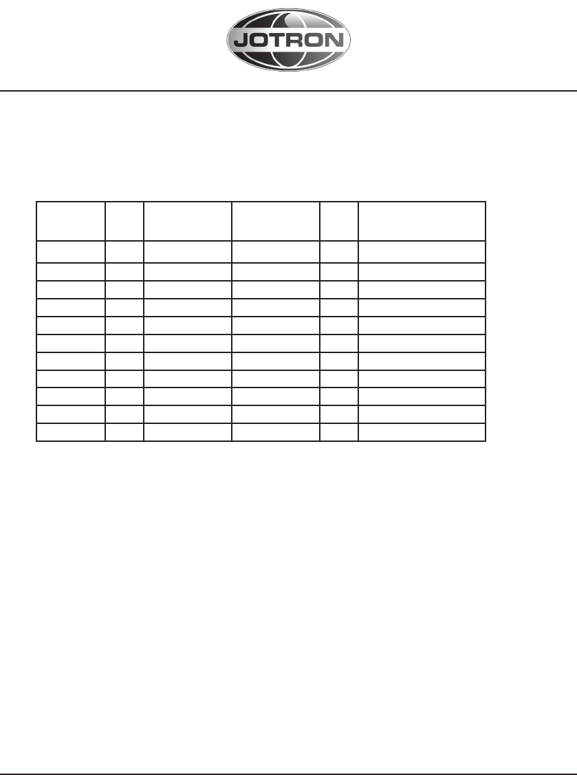
6.3 TEST AND MAINTENANCE RECORD
DATE N/T/B SIGN INSP
N= New EPIRB installed, T= Test, B= New battery

29
www.jotron.com www.jotron.com
87634_UM_TRON_40VDR_A
6.4 FALSE ALERT
False alerts transmitted by EPIRB
False alerts are a serious problem for the rescue service. Nearly 90% of EPIRB
initiated distress alerts turn out to be false alarms.
If for any reason, your EPIRB should cause a false alarm, it is most important
that you contact the nearest search and rescue authority and tell them it was a
false alarm. They can then stand down any rescue service (coast radio station
or appropriate CES or RCC). Use any means at your disposal to make contact.
Switch off the distress alarm by de-activating your EPIRB, as soon as possible.
If your beacon is activated in a non-distress situation or a distress situation
which has been resolved and you no longer require assistance, contact the
nearest search and rescue authorities via the most expeditious means available
with the following information:
• Beacon ID number (15 character UIN):
• Position (At time of activation):
• Date of Activation:
• Time of Activation (Time zone):
• Duration of Activation:
• Beacon marke and model:
• Vessel Name/lD:
• Circumstances/cause (if known):
USA
The United States search and rescue authority is the U.S. Coast Guard. The pri-
mary points of
contact are:
Pacific Ocean Area
USCG Pacific Area Command Centre
Tel: +1 (510)-437-3701
Atlantic Ocean / Gulf of Mexico Area
USCG Atlantic Area Command Centre
Tel: +1 (757)-398-6231
From Any Location
USCG Headquarters Command Centre
Tel: +1 (800)-323-7233

30
www.jotron.com www.jotron.com
87634_UM_TRON_40VDR_A
6.5 SERVICE PROCEDURE
6.5.1 WARRANTY CLAIM
Warranty claims are valid until 5 years from delivery from our warehouse. The
warranty is valid as long as service and battery replacement are carried out by
authorized Jotron distributors or agents.
All products are warranted against workmanship and factory defect, in material.
Any warranty claims must be sent to Jotron, in writing.
Jotron reserve the right to decide whether a defective unit is within warranty
terms and conditions. If Jotron make a decision of repairing a defective product,
a written description of the claim and a Jotron RMA number, should follow the
unit when returning it back to Jotron’s factory.
Please be noted that un-protective electronics board MUST be packed in anti-
static bag, before returning to Jotron’s factory.
Any costs related to transportation and/or workmanship linked up to the return
of the product being repaired shall be covered by the customer.
Jotron’s obligations during warranty replacement;
• Replace defective unit, including any programming
• Delivery terms: DAP Incoterms 2010 by regular freight to “Place” (Air-
port)
•
Service agent’s obligations during warranty claims:
• Supply replacement unit from own stock if available
• If agreed, return defective unit to Jotron
• Electronic units must be shipped in antistatic bags or covered with Jo-
tron’s plastic cover
6.5.2 SERVICE – NOT WARRANTY CLAIM
Service, such as testing, installation, programming, replacement, marking and
battery exchange are provided by an authorized Jotron service agent. Jotron do
not meet the cost for services mentioned above. Distributor or service agent
should stock the most commonly needed spare parts.
31
www.jotron.com www.jotron.com
87634_UM_TRON_40VDR_A
7 MAINTENANCE
7.1 EPIRB MODULE / BATTERY PACK
If the EPIRB is fitted on a vessel which requires GMDSS compliant equipment,
the EPIRB shall be serviced, tested and approved as required by SOLAS regu-
lation IV/15.9.2 of SOLAS 1974 as amended with, in accordance with MSC/
Circ.1039 guidelines for shore-based maintenance of Satellite EPIRBs within 5
years, or by the date of battery expiry, whichever comes first.
7.1.1 CHANGE OF BATTERY
The Tron 40VDR battery must be changed at Jotron SBM authorized workshop
to be GMDSS compliant.
If your Tron 40VDR is not under any international or national regulations, bat-
tery can be change by authorized Jotron representatives/partners/dealers.
32
www.jotron.com www.jotron.com
87634_UM_TRON_40VDR_A
7.2 HYDROSTATIC RELEASE REPLACEMENT
WARNING
Only Jotron approved hydrostatic release is acceptable for use
7.2.1 REPLACING THE RELEASE MECHANISM IN FB-40 BRACKET
1. Release and remove FB-40 top cover by removing the cotter pin (1).
WARNING! The EPIRB can drop out of the FB-40 bracket when releasing the
top cover. Remove the EPIRB from the bracket.
2. Press down the spring-loaded bracket plate and remove the hydrostatic unit
by sliding it out of its locking slot (4)
3. Check the expiry date of the new hydrostatic release mechanism. The date
should be approximately two years from the date of purchase.
4. Install a new hydrostatic unit by pressing down the spring loaded bracket
plate and sliding the unit into its locking slot (5).
5. Refit the EPIRB and the FB-40 top cover (6-7).
6. First fit the cover from the top. Mount the cutter pin then press firmly at the
bottom back cover while pressing the cover down. A “snap” sound can be
heard when the snap-lock enters (8-9).
1 2
33
www.jotron.com www.jotron.com
87634_UM_TRON_40VDR_A
3 4
5 6
7 8
9

34
www.jotron.com www.jotron.com
87634_UM_TRON_40VDR_A
8 SPARE PARTS
8.1 TRON 40VDR SPARE PARTS
X-87910 Tron 40VDR Float Free Capsule
X-89340 Tron 40VDR lower battery module incl SBM-kit
X-86218 FB-40 HRU-Kit
X-87934 Tron 40VDR Float Free Capsule user-manual
X-89339 Tron 40VDR Float Free Capsule VDR storage module.
X-87921 FB-40 docking module.
X-88237 Silicone grease for Tron 40VDR
NOTE: Keep the original satellite EPIRB packaging, since it may be needed
if the EPIRB has to be shipped for servicing. UN requirements for shipping
some batteries as hazardous goods require certain packaging standards
and labelling
8.2 COUNTERFEIT SPARE PARTS.
Jotron AS is aware of extended counterfeit spare parts being marketed and sold
to fit GMDSS safety products. It is of extreme importance that any spare parts
being fitted to this product are original spare parts, manufactured or approved
by Jotron AS. Any use of counterfeit spare parts will deviate from the product
type-approval certificates.

35
www.jotron.com www.jotron.com
87634_UM_TRON_40VDR_A
9 SERVICE AGENTS
Please look at www.jotron.com for Marine Service Agents.
Jotron Group subsidiary companies:
Jotron UK Ltd.
Crosland Park
Cramlington
NE23 1LA
United Kingdom
Tel +44 1670 712000
Fax +44 1670 590265
E-mail: sales@jotron.com
Jotron Asia Pte. Ltd.
Changi Logistics Center
19 Loyang Way #04-26
Singapore 508724
Tel +65 65426350
Fax +65 65429415
E-mail: sales@jotron.com
Jotron USA, Inc.
10645 Richmond Avenue, Suite 170
Houston, TX 77042
USA
Tel +1 713 268 1061
Fax +1 713 268 1062
E-mail: sales@jotron.com

36
www.jotron.com www.jotron.com
87634_UM_TRON_40VDR_A
10 ABBREVIATIONS AND DEFINITIONS
BAUD
Transmission rate unit of measurement for binary coded data (bit per second)
BIT
Short form of Binary Digit. The smallest element of data in a binary-coded value
BPS
Bits Per Second
COSPAS
COsmicheskaya Sistyema Poiska Avariynich Sudov (Space System for the
Search of Vessels in Distress)
EPIRB
Emergency Position Indicating Radio Beacon
GLOBAL POSITIONING SYSTEM (GPS)
The NAVSTAR Global Positioning System, which consists of orbiting satellites, a
network of ground control stations, and user positioning and navigation equip-
ment. The system has 24 satellites plus 3 active spare satellites in six orbital
planes about 20,200 kilometers above the earth.
IEC
International Electro-technical Commission
IMO
International Maritime Organization
IBRD
International 406MHz Beacon Registration Database
ITU
International Telecommunication Union
LED
Light Emitting Diode
LUT
Local User Terminal (Ground Station)
MCA
Marine and Coastguard Agency (UK)
MCC
Mission Control Centre
NOAA
National Oceanic and Atmospheric Administration (USA)

37
www.jotron.com www.jotron.com
87634_UM_TRON_40VDR_A
RCC
Rescue Coordination Centre
SARSAT
Search and Rescue Satellite-Aided Tracking System
SBM
Shore Based Maintenance – as required by SOLAS regulation IV/15.9.2 of
SOLAS 1974 as amended with, in accordance with MSC/Circ. 1039 guidelines for
Shore-Based Maintenance (SBM) of Satellite EPIRBs within 5 years if:
Passenger ships (> 12 passengers) and cargo ships (> 300GT) engaged in Inter-
national voyages, shall perform SBM as follows:
• Latest by the date of the EPIRB label with this text, or the battery Label,
whichever is first.
• When this EPIRB becomes due for SBM in accordance with national
requirements.
VDR
Voyage Data Recorder.
VHF
Very High Frequency -A set of frequencies in the 30-300MHz region.
38
www.jotron.com www.jotron.com
87634_UM_TRON_40VDR_A
11 AMENDMENT RECORDS
Amend-
ment no
By Date Page(s) Vers. Reason for change
1 SEH 07.05.2014 Total 37 A New Manual

v.J
Jotron AS (HQ)
P.O.Box 54
3281 Tjodalyng
Norway
Tel: +47 33 13 97 00
Fax: +47 33 12 67 80
sales@jotron.com
CONTACT INFORMATION
Jotron AS
P.O.Box 23
3195 Skoppum
Norway
Tel: +47 33 13 97 00
Fax: +47 33 12 67 80
sales@jotron.com
Jotron AS
Dølasletta 7
3408 Tranby
Norway
Tel: +47 32 84 53 87
Fax: +47 32 84 55 30
sales@jotron.com
Jotron UK Ltd.
Crosland Park
Cramlington
NE23 1LA
United Kingdom
Tel: +44 (0) 1670 712000
Fax: +44 (0) 1670 590265
sales@jotron.com
Jotron USA, Inc.
10645 Richmond Avenue, Suite 170
Houston, TX 77042
USA
Tel: +1 713 268 1061
Fax: +1 713 268 1062
sales@jotron.com
Jotron Asia Pte. Ltd.
19 Loyang Way
Changi Logistics Centre
Rear Office Block 04-26
Singapore 508724
Tel: +65 65426350
Fax: +65 65429415
sales@jotron.com
www.jotron.com www.jotron.com