Jotron AS TRONTR30 Maritime VHF GMDSS Radio User Manual My
Jotron AS Maritime VHF GMDSS Radio My
Contents
- 1. 01. Tron TR30 GMDSS and Maritime VHF Radio vB print (00C)__
- 2. 04. Tron TR30 vA DRAFT 26-10-16_Read only-NOT FOR PRINT__
04. Tron TR30 vA DRAFT 26-10-16_Read only-NOT FOR PRINT__

www.jotron.com
www.jotron.com
USER MANUAL
Tron TR30

Page - 3 -
Table of contents
1 List of figures 7
2 Abbreviations 8
3 General 10
4 Standards 12
5 Product description 16
5.1 Product image 18
6 Emergency battery and emergency test battery safety instructions20
6.1 Hazards identification 21
6.2 First aid measures 22
6.3 Fire fighting measures 22
6.4 Accidental release measures 23
6.5 Handling and storage 23
6.5.1 Transportation 24
7 Rechargeable battery safety instructions 25
7.1 Hazards identification 26
7.2 First aid measures 27
7.3 Fire fighting measures 27
7.4 Accidental release measures 28
7.5 Handling and storage 29
7.5.1 Transportation 29
8 Functional description 30

Page - 4 -
8.1 Tron TR30 components 30
8.2 Battery charger components 32
8.3 Antenna 33
8.4 Emergency battery (GMDSS) 33
8.5 Battery endurance 34
8.5.1 Battery charger 35
9 Technical specifications 37
9.1 Product specification 37
10 Installation 39
10.1 Changing the battery 40
11 Operation instructions (GMDSS radio) 42
11.1 Emergency mode 42
11.2 Channel selection 43
11.3 Channel 16 button 43
11.4 Volume adjustment 44
11.5 Squelch adjustment 44
11.6 Lock and unlock 45
11.7 External accessories 46
11.8 Watch 46
11.8.1 Dual watch 47
11.9 Menus 47
12 Operation instructions (Maritime VHF radio) 52

Page - 5 -
12.1 Regular radio mode 52
12.2 Channel selection 52
12.3 Channel 16 button 53
12.4 Call channel 54
12.5 Custom channels 55
12.6 Volume adjustment 56
12.7 Squelch adjustment 56
12.8 Lock and unlock 57
12.9 External accessories 57
12.10 Watch 58
12.10.1 Dual watch 58
12.10.2 Triple watch 59
12.10.3 Scan 61
12.11 Menus 63
13 Maintenance 69
13.1 Taking care of a Tron TR30 69
13.2 Regular testing 70
13.3 Cleaning of dirt and oil 71
14 Test and maintenance records 72
15 Channels and frequencies 73
15.1 GMDSS 73
15.2 International 74


Page - 8 -
2 Abbreviations
ADR European Agreement concerning the International Carriage of
Dangerous Goods by Road
CFR The Code of Federal Regulations
DW Dual Watch (Receiver altering between two different channels)
ECHA European Chemical Agency
EMC Electromagnetic compatibility
ESD Electrostatic discharge
ETS European Telecommunications Standard
ETSI European Telecommunications Standards Institute
GMDSS Global Maritime Distress and Safety System
HW Hardware
IATA International Air Transport Association
ICAO International Civil Aviation Organization
IEC International Electrotechnical Commission
IMDG International Maritime Dangerous Goods Code
MHz MegaHertz
MSDS Material Safety Data Sheet
OSHA Occupational Safety and Health Admin
RES Radio equipment and systems (technical committee of ETSI)
RID Reglement concernant le transport International ferroviare des
merchandises Dangereuses par chemin de fer (Transportation
of Dangerous Goods by Train)
RMA Return Material Authorization number
Page - 9 -
RSS Radio Standards Specification
SDS Safety Data Sheet
SMA Sub miniature version A connector
SOLAS Safety of Life at Sea (An international maritime safety treaty)
STCW Standards of training, certification and watch keeping for
seafarers
SW Software
TW Triple Watch
UN United Nations
VAC Volts, alternating current (AC)
VHF Very High Frequency

Page - 10 -
3 General
Jotron manufactures safety equipment designed for the search and rescue of human
life and property. For safety equipment to be effective according to the design
parameters it is imperative that all products are handled, maintained, serviced and
stowed in compliance with the manufacturer's instructions.
Copies of all Jotron documentation can be downloaded from our website:
www.jotron.com.
All information contained within this manual has been verified and is to our knowledge
correct, however, Jotron reserves the right to make changes to any product(s) or
module(s) described herein to improve reliability, function or design, without further
notice.
The following four symbols are in use throughout this manual:
This symbol is used to highlight information.
This symbol is used to draw attention to important details.
Page - 11 -
This symbol is used to highlight information that if not followed can
result in damage to a product or equipment.
This symbol is used to highlight information that if not followed can
result in personal injury or bodily harm.
Jotron is not liable for consequential or special damages and cannot
be held responsible for any damages or injury arising either directly or
indirectly due to an error or omission of information, misuse of a
product, breach of procedures, or for failure of any specific
component or other part of the equipment.
Page - 12 -
4 Standards
The Tron TR30 (emergency mode - GMDSS) has been verified, tested and meets the
following product standards:
EN/IEC 60945: 2002 including
Corr.1
(Category - Portable)
Maritime navigation and radio communication
equipment and systems - General requirements -
Methods of testing and required test results.
ETSI EN 300 225, V1.4.1 (2004-
12)
Electromagnetic compatibility and Radio
spectrum Matters (ERM); Technical characteristics
and methods of measurement for survival craft
portable VHF radiotelephone apparatus.
ETSI EN 301 843-1, V1.2.1
(2004-06)
Electromagnetic compatibility and Radio
spectrum Matters (ERM); ElectroMagnetic
Compatibility (EMC) standard for marine radio
equipment and services; Part 1: Common technical
requirements
ETSI EN 301 843-2, V1.2.1
(2004-06)
Electromagnetic compatibility and Radio
spectrum Matters (ERM); ElectroMagnetic
Compatibility (EMC) standard for marine radio
equipment and services; Part 2: Specific
conditions for VHF radiotelephone transmitters
and receivers.
IEC 61097-12: 1996 Global maritime distress and safety system
(GMDSS) - Part 12: Survival craft portable two-way
VHF radiotelephone apparatus - Operational and
performance requirements, methods of testing
and required test results
RSS-102, Issue 5: Mar. 2015 Radio Frequency (RF) Exposure Compliance of
Radio communication Apparatus (All Frequency
Page - 13 -
Bands).
RSS-182, Issue 5: Jan. 2012 Maritime Radio Transmitters and Receivers in the
Band 156-162.5 MHz.
Tron TR30 (regular mode - VHF) has been verified, tested and meets the following
product standards:
EN 62479: 2010 Assessment of the compliance of low power
electronic and electrical equipment with the basic
restrictions related to human exposure to
electromagnetic fields (10 MHz to 300 GHz)
ETSI EN 301 178-1, V1.3.1: 2007-
02
Electromagnetic compatibility and Radio
spectrum Matters (ERM); Portable Very High
Frequency (VHF) radiotelephone equipment for the
maritime mobile service operating in the VHF
bands (for non-GMDSS applications only); Part 1:
Technical characteristics and methods of
measurement
ETSI EN 301 178-2, V1.2.2:
2007-02
Electromagnetic compatibility and Radio
spectrum Matters (ERM); Portable Very High
Frequency (VHF) radiotelephone equipment for the
maritime mobile service operating in the VHF
bands (for non-GMDSS applications only); Part 2:
Harmonized EN covering essential requirements of
article 3.2 of the R&TTE Directive
ETSI EN 301 843-1, V1.2.1 (2012-
08)
Electromagnetic compatibility and Radio
spectrum Matters (ERM); ElectroMagnetic
Compatibility (EMC) standard for marine radio
equipment and services; Part 1: Common technical
requirements
ETSI EN 301 843-2, V1.2.1 Electromagnetic compatibility and Radio

Page - 14 -
(2004-06) spectrum Matters (ERM); ElectroMagnetic
Compatibility (EMC) standard for marine radio
equipment and services; Part 2: Specific
conditions for VHF radiotelephone transmitters
and receivers.
IEC 62209-1:2005 Human exposure to radio frequency fields from
hand-held and body-mounted wireless
communication devices - Human models,
instrumentation, and procedures - Part 1:
Procedure to determine the specific absorption
rate (SAR) for hand-held devices used in close
proximity to the ear (frequency range of 300 MHz
to 3 GHz)
IEC 62209-2: 2010 Human exposure to radio frequency fields from
hand-held and body-mounted wireless
communication devices - Human models,
instrumentation, and procedures - Part 2:
Procedure to determine the specific absorption
rate (SAR) for wireless communication devices
used in close proximity to the human body
(frequency range of 30 MHz to 6 GHz)
IEC 62368-1:2014 Audio/video, information and communication
technology equipment - Part 1: Safety
requirements
Regulations for VHF radios varies from country to country. Prior to
using this equipment check the national requirements for VHF radio
operators and ensure that the radio conforms to all local regulations.

Page - 15 -
47 CFR 2.1093: Oct. 2013 Radio frequency radiation exposure evaluation:
portable devices.
47 CFR 80 to End: Oct. 2015 Electronic Code of Federal Regulations, Title 47,
Telecommunications
All
statements
of
conformity
are
available
at:
www.jotron.com
This device complies with the GMDSS provision
of part 80 of
the FCC Rules.
Any changes or modifications not expressly
approved by the party responsible for compliance could void the
user's authority to operate this equipment.
Page - 16 -
5 Product description
The Tron TR30 is a ruggedly designed radio made for easy operation. It is a portable
survival craft two-way VHF radio which is possible to operate using one hand, even
when wearing gloves. The high contrast graphical display including integrated back
lighting of the display and keys are very effective for visibility and usage in low light
conditions.
It is also resistant to oil, seawater and sunlight. This radio is compact in size with
smooth edges to avoid damage to clothing or a raft. The highly visible orange housing
is made from glass reinforced polycarbonate.
The Tron TR30 GMDSS (emergency mode) radio is waterproof down to 1 meter and
floats in freshwater, battery included. The radio is designed with a self draining
loudspeaker. The Tron TR30 is only completely waterproof when the antenna and jack
cover are assembled on the radio correctly.
The Tron TR30 (GMDSS - emergency mode) radio includes the following components:
• Tron TR30 radio
• Emergency GMDSS battery (orange)
• Antenna
• Belt clip
• Wrist strap
Part number: 83446 Tron TR30
The Tron TR30 Maritime VHF (regular mode) radio includes the following components:
• Tron TR30 radio
• Emergency GMDSS battery (orange)
• Rechargeable battery (black)
Page - 17 -
• Battery charger
• Antenna
• Belt clip
• Wrist strap
Part number: 87950 Tron TR30
Page - 18 -
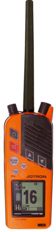
5.1 Product image
Figure 1 Tron TR30
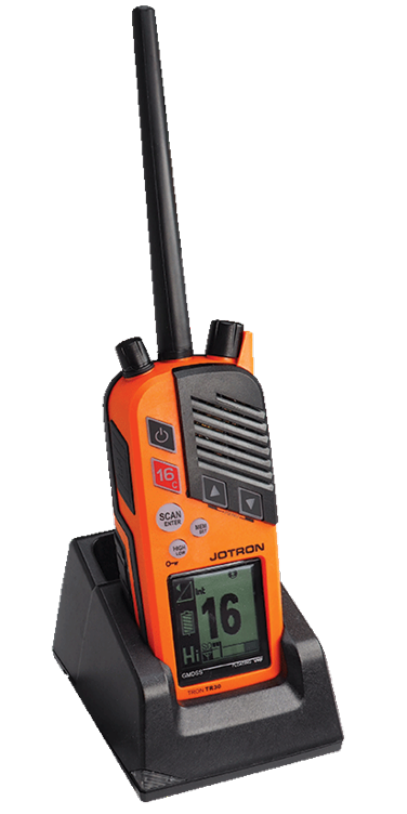
Page - 19 -
Figure 2 Tron TR30 in the battery charger
Page - 20 -
6 Emergency battery and
emergency test battery
safety instructions
Under EC, European Chemical Agency (ECHA) and US, Occupational Safety and Health
Admin (OSHA) legislation this product is classified as a manufactured article, which
does not release or otherwise result in exposure to a hazardous chemical under the
normal conditions of use. Therefore, this product is exempt from the requirement of a
dedicated Material Safety Data Sheet (MSDS) or Safety Data Sheet (SDS).
The following information is included in this manual as guided safety instructions.
Product name: Emergency battery
Type no.: FR6
Lithium metal content: 2 x 1.96 gram lithium pr battery
Approximate weight: 100 grams
Chemical system: Lithium Iron Disulphide
Designed for recharge: No
Below are instructions for keeping the radio log and the radio operator's obligation
according to national and international regulation:
1. The radio log shall be kept in accordance with requirements in the Radio
Regulation, SOLAS Convention, national regulations regarding radio
installations and the STCW Convention (STCW 95 including the STCW Code)
including relevant regulation regarding watch keeping on board passenger and
cargo ships.
Page - 21 -
2. Unauthorized transmissions and incidents harmful interference should, if
possible, be identified, recorded in the radio log and brought to the attention of
the Administration in compliance with the Radio Regulations, together with an
appropriate extract from the radio log (STCW Code BVIII/2 No. 32).
Testing of radio equipment and reserve source of energy should occur:
The below safety information is extracted from EVE Energy SDS
(sections 4, 5 & 6).
6.1 Hazards identification
The lithium thionyl chloride batteries used in the Tron TR30 and described herein are
sealed units.
Under normal conditions, the battery is hermetically sealed. These batteries are not
hazardous when used as intended and recommended.
Do not short circuit, recharge, puncture, incinerate, crush, immerse,
force discharge or expose to temperatures above the declared
operating temperature range of the product, otherwise you risk fire or
explosion.
Ingestion: Swallowing a battery can be harmful.
Inhalation: Contents of an open battery can cause
respiratory irritation.

Page - 22 -
Skin contact: Contents of an open battery can cause skin
irritation.
Eye contact: Contents of an open battery can cause severe
irritation.
6.2 First aid measures
Ingestion: Do not induce vomiting or consume food or drink.
Seek medical attention immediately.
Inhalation: Provide fresh air and seek medical attention.
Skin contact: Remove contaminated clothing and shoes and
wash skin with soap and water. Wash clothing and
shoes prior to reuse. If irritation occurs, seek
medical attention.
Eye contact: Immediately flush eyes thoroughly with water for
at least 15 minutes, lifting upper and lower lids,
until no evidence of the chemical remains. Seek
medical attention.
6.3 Fire fighting measures
In case of fire where lithium batteries are present, flood area with water or smother
with a Class D fire extinguisher appropriate for lithium metal, such as Lith-X. Water
may not extinguish burning batteries but will cool the adjacent batteries and control
spreading fire. Burning batteries will burn themselves out.
Virtually all fires involving lithium batteries can be controlled by flooding with water,
however, the contents of the battery will react with water and form hydrogen gas. In a
confined space, hydrogen gas can form an explosive mixture. In this situation, a

Page - 23 -
smothering agent is recommended. A smothering agent will extinguish burning lithium
batteries.
Any person responding to such an emergency should wear a self-
contained breathing apparatus.
Burning lithium iron disulphide batteries produces toxic and corrosive
lithium hydroxide fumes and sulfur dioxide gas.
6.4 Accidental release measures
To clean up a leaking battery:
Ventilation requirements: Room ventilation may be in areas where there are
open or leaking batteries.
Respiratory protection: Avoid exposure to electrolyte fumes from an
open or leaking battery.
Eye protection: Wear safety glasses with side shields if handling
an open or leaking battery.
Gloves: Use neoprene or natural rubber gloves when
handling an open or leaking battery. Battery
materials should be disposed of in a leak-proof
container.
6.5 Handling and storage
The Tron TR30 should be stored in a cool and well ventilated area. Elevated
temperatures can result in a reduction of battery life. In locations that handle large
quantities of lithium batteries, such as a warehouse, lithium batteries should be
isolated from unnecessary combustibles.

Page - 24 -
A battery that is installed backwards, disassembled, charged or is
exposed to water, fire or high temperatures can explode or leak
causing burns.
6.5.1 Transportation
Detailed support documentation regarding transportation
regulations for batteries in accordance with ICAO/IATA, IMDG code
and/or ADR/RID can be found at www.jotron.com, under Product
Safety Information (PSI) and/or statement in accordance with UN
test 38.3
Page - 25 -
7 Rechargeable battery safety
instructions
Under EC, European Chemical Agency (ECHA) and US, Occupational Safety and Health
Admin (OSHA) legislation this product is classified as a manufactured article, which
does not release or otherwise result in exposure to a hazardous chemical under the
normal conditions of use. Therefore, this product is exempt from the requirement of a
dedicated Material Safety Data Sheet (MSDS) or Safety Data Sheet (SDS).
The following information is included in this manual as guided safety instructions.
Product name: Rechargeable battery (LiPo 1550 mAh)
Type no.: GEP653759
Lithium metal content: 0.9 gram lithium pr battery and 11.47 What-Hour
rating(Kwh)
Approximate weight: 100 grams
Chemical system: Lithium Polymer
Designed for recharge: Yes
Below are instructions for keeping the radio log and the radio operator's obligation
according to national and international regulation:
1. The radio log shall be kept in accordance with requirements in the Radio
Regulation, SOLAS Convention, national regulations regarding radio
installations and the STCW Convention (STCW 95 including the STCW Code)
including relevant regulation regarding watch keeping on board passenger and
cargo ships.
Page - 26 -
2. Unauthorized transmissions and incidents harmful interference should, if
possible, be identified, recorded in the radio log and brought to the attention of
the Administration in compliance with the Radio Regulations, together with an
appropriate extract from the radio log (STCW Code BVIII/2 No. 32).
Testing of radio equipment and reserve source of energy should occur:
Monthly: Handheld VHF transceivers are to be tested using a test or rechargeable
battery.
The below safety information is extracted from Green Energy Battery
and MSDS info from Pony Test Lab's report (sections 4, 5 & 6).
7.1 Hazards identification
The lithium thionyl chloride batteries used in the Tron TR30 and described herein are
sealed units.
Under normal conditions, the battery is hermetically sealed. These batteries are not
hazardous when used as intended and recommended.
Do not short circuit, recharge, puncture, incinerate, crush, immerse,
force discharge or expose to temperatures above the declared
operating temperature range of the product, otherwise you risk fire or
explosion.

Page - 27 -
Ingestion: Swallowing a battery can be harmful.
Inhalation: Contents of an open battery can cause
respiratory irritation.
Skin contact: Contents of an open battery can cause skin
irritation.
Eye contact: Contents of an open battery can cause severe
irritation.
7.2 First aid measures
Ingestion: Do not induce vomiting or consume food or drink.
Seek medical attention immediately.
Inhalation: Provide fresh air and seek medical attention.
Skin contact: Remove contaminated clothing and shoes and
wash skin with soap and water. Wash clothing and
shoes prior to reuse. If irritation occurs, seek
medical attention.
Eye contact: Immediately flush eyes thoroughly with water for
at least 15 minutes, lifting upper and lower lids,
until no evidence of the chemical remains. Seek
medical attention.
7.3 Fire fighting measures
In case of fire where lithium batteries are present, use an extinguishing agent suitable
for the location and surrounding environment, such as CO₂.
A battery may burst and release hazardous decomposition products when exposed to
fire. Lithium ion batteries contain flammable electrolyte that may vent, ignite and

Page - 28 -
produce sparks when subjected to high temperatures (›150°C/302°F), when damaged
or abused (e.g. mechanical damage or electrical overcharging), may burn rapidly with
flare-burning effect; may ignite other batteries in close proximity.
Any person responding to such an emergency should wear a self-
contained breathing apparatus.
Burning lithium iron disulphide batteries produces toxic and corrosive
lithium hydroxide fumes and sulfur dioxide gas.
7.4 Accidental release measures
Personal precautions: Wear the proper personal protective equipment.
Keep unprotected individuals away. Ensure
adequate ventilation.
Emergency procedures: Remove ignition sources, evacuate the area.
Sweep up using a method that does not generate
dust. Collect as much of the spilled material as
possible, place the spilled material into an
appropriate disposal container. Keep spilled
material out of sewers, ditches and bodies of
water.
Environmental precautions: Do not allow material to be released into the
environment without proper governmental
permits.
Methods and materials for
containment and cleaning up:
All waste must refer to the United Nations, the
national and local regulations for disposal.
Page - 29 -
7.5 Handling and storage
The Tron TR30 should be stored in a cool and well ventilated area. Elevated
temperatures can result in a reduction of battery life. In locations that handle large
quantities of lithium batteries, such as a warehouse, lithium batteries should be
isolated from unnecessary combustibles.
A battery that is installed backwards, disassembled, charged or is
exposed to water, fire or high temperatures can explode or leak
causing burns.
7.5.1 Transportation
Detailed support documentation regarding transportation
regulations for batteries in accordance with ICAO/IATA, IMDG code
and/or ADR/RID can be found at www.jotron.com, under Product
Safety Information (PSI) and/or statement in accordance with UN
test 38.3
Page - 30 -
8 Functional description
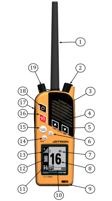
8.1 Tron TR30 components
An overview of the radio components.
Figure 3 Tron TR30 components
Page - 31 -
1 Antenna
2 Volume, squelch and monitor control
3 Loudspeaker
4 Up arrow button
5 Down arrow button
6 Mem set (memory button)
7 Emergency mode indicator
8 Channel designator
9 Microphone
10 Squelch andsignal strength indicator
11 Hi/medium/low (transmitter power indicator)
12 Battery charge indicator
13 Volume control indicator
14 High/Low button
15 Scan/Enter
16 Instant access channel 16 and call channel
17 Transmit button
18 On/off button
19 Jack cover (black knob)/External handset connector (inside)
Page - 32 -
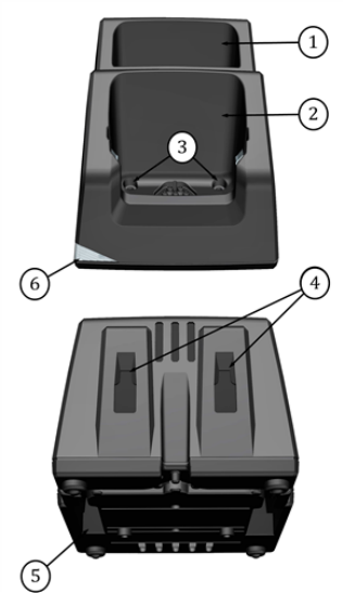
8.2 Battery charger components
An overview of the battery charger components.
Figure 4 Battery charger components
1 Battery charger storage
2 Battery charger bay
3 Table mounting holes (42.7mm spacing)
4 Wall mounting holes (36.0mm spacing)
5 Power input
6 LEDindicator
Page - 33 -
8.3 Antenna
The antenna for the Tron TR30 is fitted with a standard SMA connector. You can also
connect a remote antenna for a fixed application.
The Tron TR30 unit is not waterproof when the standard antenna is
not attached or if the antenna is not assembled correctly.
8.4 Emergency battery (GMDSS)
The emergency battery unit is a lithium battery. This battery is specially designed for
GMDSS emergency use, to preserve a long shelf and operating life, the battery cannot
be recharged. For safety reasons the battery and battery charger are designed such
that an emergency battery may be stored but not charged.
The emergency battery is a single use item. You must replace the
battery before the battery expiry date and/or if the protective seal on
the battery is broken.
It is safe to store the emergency battery in the charger.
Always bring a sealed emergency battery with the radio when
boarding a lifeboat or raft.
Page - 34 -
Doing any of the following could result in sever burn hazard or fire
explosion:
• Heating a lithium battery over 70 degrees celsius
• Attempting to recharge the battery.
• Crushing, disassembling or attempting to ignite or set flame to
the battery.
8.5 Battery endurance
Below is a list of the operation times of the battery and usage.
It is recommended you use medium or low power when possible in
order to maximize the operational time of the battery.
Battery type Hours of usage*
Standby time Multi-usage **
Emergency battery 70 12
Rechargeable battery 50 12
* The hours indicated are based on 2W (tested at -20 degrees
celsius).
** Emergency battery multi-usage hours have been tested in
accordance with 10:10:80 ratio (Send%:Listen%:Standby%).
** Rechargeable battery multi-usage hours have been tested in
Page - 35 -
accordance with 5:5:90 ratio (Send%:Listen%:Standby%).
For more information refer to the ETS 300 225 standard.
8.5.1 Battery charger
The RCH-30 battery charger can charge the radio and/or battery. In addition, the
charger also has one extra storage area for an emergency battery.
The battery charger is not waterproof and must therefore be
protected from elements.
The charger will not charge a battery if the battery temperature is
below 0˚C or above 40˚C.
In either case, the rechargeable battery should be left in the charger.
The charger automatically begins to charge when it reaches an
appropriate cell temperature for charging.
To reduce the charging time it is recommended that the battery is
changed at room temperature (15°C to 25°).
Page - 36 -
The battery charging indicator on the screen display shows the approximate status of
the battery and indicates when recharging is necessary. Leaving the radio switch on
will increase the charging time.

Page - 37 -
9 Technical specifications
9.1 Product specification
Overall:
Emergency mode
(emergency battery)
Channel spacing 25 kHz
Operating temperature range -20 to +55
Size (W/H/D) 61mm x 157mm x 40mm (Dept with belt clip
47mm)
Full buoyancy Yes
Weight Approximately 300 g
Receiver:
Emergency mode
(emergency battery)
Frequency range TX: 154-157.425MHz / RX: 156-162 MHz
Maximum usable sensitivity < 1 µV for 20dB SINAD
Adjacent channel rejection > 70dB
Blocking > 90dB
Spurious response > 70dB
Harmonic distortion* < 5%
Inter-modulation rejection > 68dB
Channel monitoring DW
Page - 38 -
Transmitter:
Emergency mode
(emergency battery)
Frequency range TX: 154-157.425MHz / RX: 156-162 MHz
Transmitter output power (fully
charged battery)
Low: 1W, High: 2W
Harmonics and spurious < 0.25 µW
Frequency error < +1.5 kHz
Adjacent channel power < -70dB
The nominal viewing distance is 0.8m.
Page - 39 -
10 Installation
Connect the adapter to the charger prior to first time use.
To install, do the following:
1. Connect the antenna.
When assembling the antenna to the radio, ensure you hold it
at the base while turning it clockwise. When the antenna starts
to resist turning, turn it another 90 degrees.
Holding the antenna anywhere but at the base during assembly
will damage it.
2. Insert the radio or battery into the provided battery charger.
Do not force the battery, the battery only fits into the battery
charger one way.
3. Ensure that the battery or radio is sitting properly in the charger.
4. Plug in the charger.

Page - 40 -
A yellow light indicates the unit is charging.
A green light indicates the battery is fully charged.
A red light indicates there is a fault.
5. Place the radio in a location away from direct sea spray, chemicals, oil and
vibration.
The Tron TR30 must be easily accessible at all times for testing and
maintenance.
There are two screw holes available such that the charger can be
securely mounted to a flat surface.
10.1 Changing the battery
To change the Tron TR30 battery, do the following:
1. Press the ON/OFF button to turn off the radio.
2. Press both the new battery release clips, to release the battery.
3. Gently pull the top of the battery backwards, away from the radio.
4. Put the lower end of the battery into the fixing track at the bottom of the radio.
5. Flip the battery into position, make sure the battery clips fully engage.

Page - 41 -
The radio is only watertight when the battery, antenna and jack cover
correctly assembled.
Battery replacement must be done in a dry environment or under
shelter.
Page - 42 -
11 Operation instructions
(GMDSS radio)
11.1 Emergency mode
When the emergency battery is connected, the radio starts in the emergency mode.
Only basic functionality is available to the user in this mode. This battery is for use in a
distress situation.
If the jack cover is removed, for example when using an accessory,
the radio is no longer waterproof.
The antenna and jack cover must be correctly assembled on the
radio in order for it to be completely waterproof.
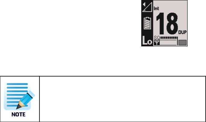
Function: Display screen:
Turning on a radio using an emergency battery. The circle in
the top right corner appears when the radio is in the
emergency mode.
1. Press and hold the power button for approximately 3 seconds to turn the radio
on.
The radio loads the following settings:
• Channel 16
• Max power level (2W)
• High volume
• Low squelch
Page - 43 -
11.2 Channel selection
Function:
Channel selection
1. Press or press and hold the up/down arrow buttons to change the channel.
When a emergency battery is connected, only GMDSS channels
are available.
For information regarding available and active VHF marine radio
channels and frequencies, please refer to ITU standards, with
reference to the current World Radio Conference (WRC) agreement.
For an overview, refer to the Navigation Center website
(www.navcen.uscg.gov, under Maritime Information, Maritime
Telecommunications)
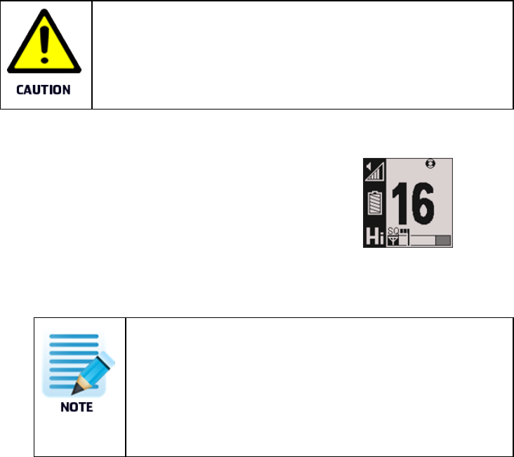
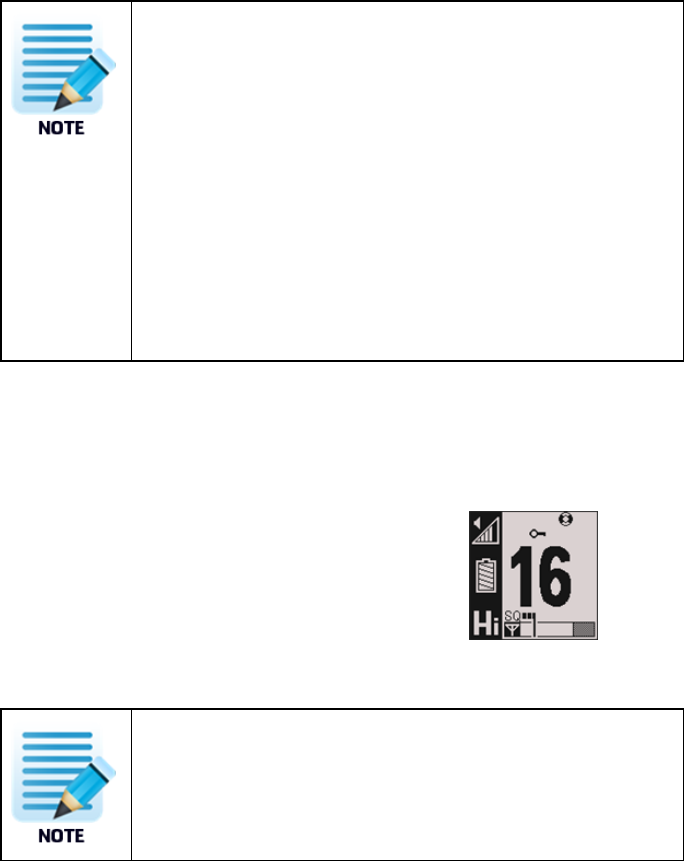
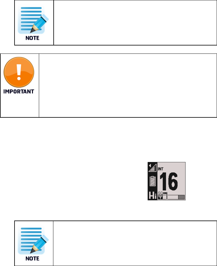
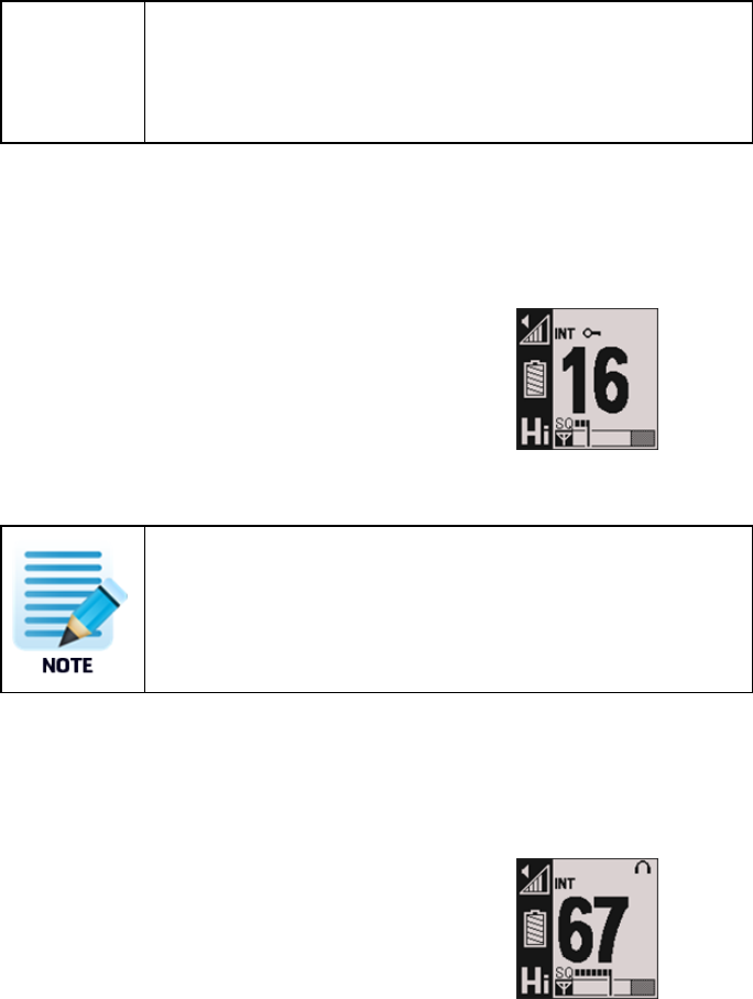
11.3 Channel 16 button
Function: Display screen:
Channel 16
1. Press the 16 button to jump directly to channel 16.
Page - 44 -
The transmit power will always be set to Hi power when using
the channel 16 button, even if you switch from another channel.
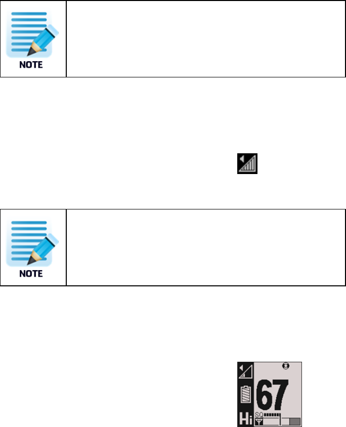
11.4 Volume adjustment
Function: Display screen:
Volume adjustment
1. Turn the knob to adjust the volume.
The volume symbol in the display indicates the volume level.
Ensure that you do not press the knob while adjusting the
volume.
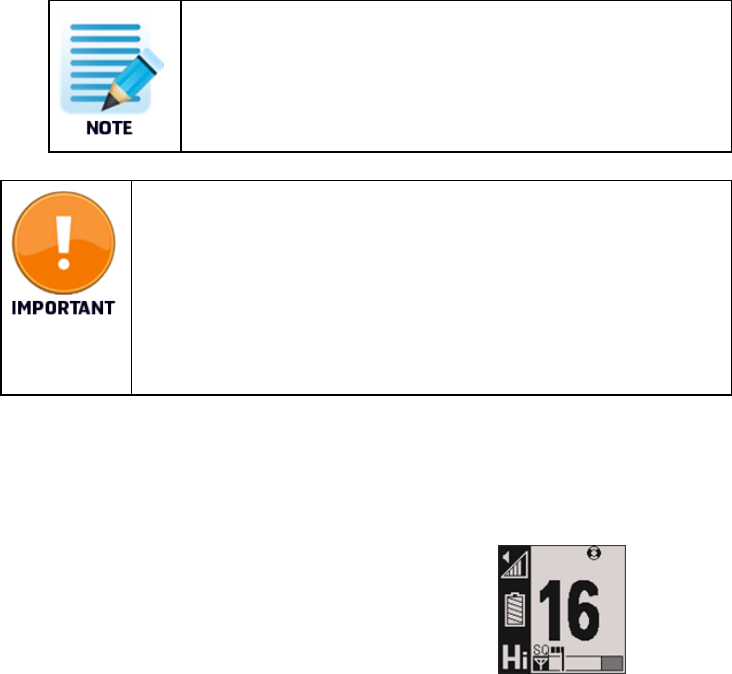
11.5 Squelch adjustment
Function: Display screen:
Squelch adjustment
1. Press and turn the knob clockwise to reduce sensitivity.
Page - 45 -
When the knob is pressed twice, it opens the squelch
immediately.
The squelch bar appears on the screen display indicating the
current active sensitivity level. When adjusted fully to the left,
the squelch is completely open, adjusting to the right lowers
the sensitivity.
The signal strength of the current channel appears on the bar
below the squelch bar. If the received signal is strong enough,
the squelch opens and voice is received. This is indicated by the
Rx symbol.
11.6 Lock and unlock
Function: Display screen:
Lock/Unlock
1. Press and hold the HI/LO button for 2 seconds to lock or unlock the radio.
A key symbol appears when the radio is locked.
Page - 46 -
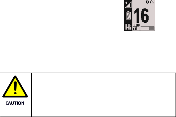
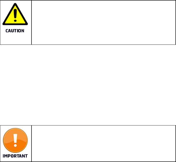
11.7 External accessories
Function: Display screen:
External accessories
The headphone symbol appears in the display screen when you connect an external
accessory, such as a headphone, microphone or external PTT.
Connector type: 3,5mm 4 pole jack.
When using an accessory, the radio is no longer waterproof.
The antenna and jack cover must be correctly assembled on the
radio in order for it to be completely waterproof, it is therefore not
recommended to use accessories while using the Tron TR30 in the
emergency mode.
11.8 Watch
When the radio is in the emergency mode, it can only check for signals or watch in one
way:
1. Dual watch
DW listens to the working channel and channel 16.
Page - 47 -
The radio will continue to watch channel 16 while receiving on other
channels.
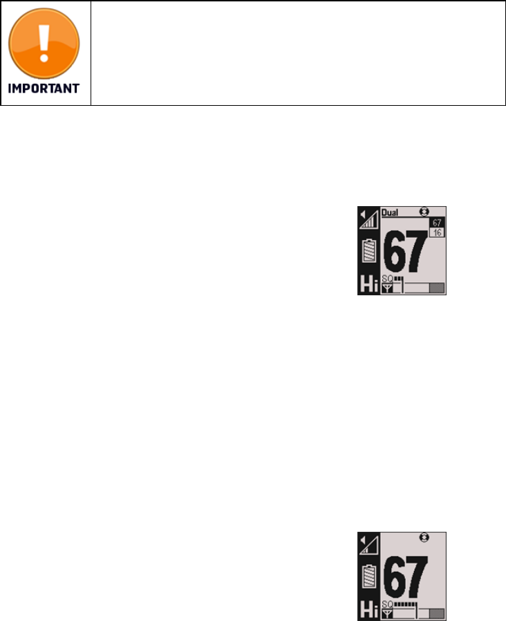
11.8.1 Dual watch
Function: Display screen:
Dual watch (DW)
The DW function allows the user to monitor channel 16 and
one selected channel alternately.
To activate or deactivate DW, do the following:
1. Press Scan to activate dual watch.
2. Press the up/down buttons to watch a second channel.
3. Press Scan a second time to deactive dual watch.
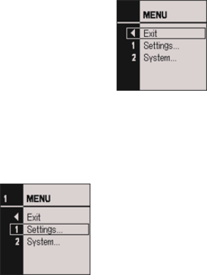
11.9 Menus
Menus: Display screen:
Page - 48 -
Press the up/down arrow buttons at the same time to enter/exit the menu system.
Use the up/down arrow buttons to navigate and select using Scan/Enter.
Exit: Display screen:
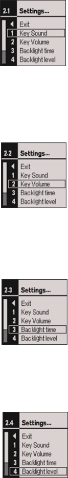
Settings: Display screen: Menu number:
Use this menu option to adjust the
following settings:
• Key sound
• Key volume
• Backlight time
• Backlight level
• Contast
• Key lock time
1
Key sound: Display screen: Menu number:
Page - 49 -
1
Key volume: Display screen: Menu number:
2
Backlight time: Display screen: Menu number:
3
Backlight level: Display screen: Menu number:
• fff, low, high (0,1,2) 4
Page - 50 -
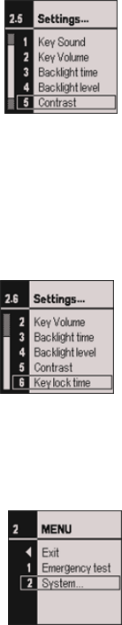
Contrast: Display screen: Menu number:
5
Key lock time: Display screen: Menu number:
6
System: Display screen: Menu number:
Use this menu option to access the
following information:
• Serial Number
• SW version
• HW version
2
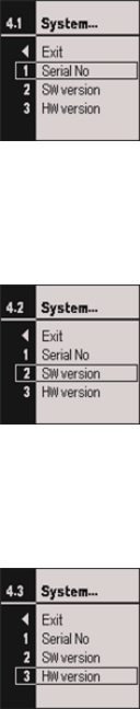
Serial Number: Display screen: Menu number:
Page - 51 -
1
SW Version: Display screen: Menu number:
2
HW Version: Display screen: Menu number:
3
Page - 52 -
12 Operation instructions
(Maritime VHF radio)
12.1 Regular radio mode
When the rechargeable battery is connected additional functionality is available. All
VHF channels are available with triple watch and custom channel scan. In addition,
three transmit power levels are also available.
Function Display
Turning on a radio using a rechargeable battery.
1. Press and hold the power button for approximately 3 seconds to turn the radio
on.
The radio loads settings based on previous usage.
12.2 Channel selection
Function:
Channel selection
Page - 53 -
1. Press or press and hold the up/down arrow buttons to change the channel.
When a primary battery is connected, only GMDSS channels are
available.
For information regarding available and active VHF marine radio
channels and frequencies, please refer to ITU standards, with
reference to the current World Radio Conference (WRC) agreement.
For an overview, refer to the Navigation Center website
(www.navcen.uscg.gov, under Maritime Information, Maritime
Telecommunications)
12.3 Channel 16 button
Function: Display screen:
Channel 16
1. Press the 16 button to jump directly to channel 16.
The transmit power will always be set to Hi power when using
the channel 16 button, even if you switch from another channel.
Page - 54 -
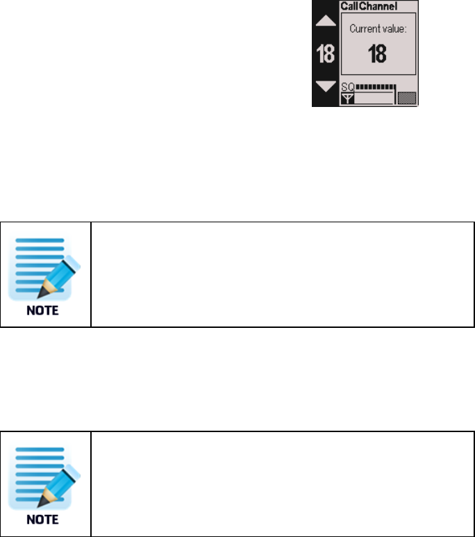
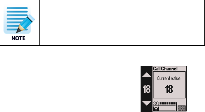
12.4 Call channel
Function: Display screen:
Call channel
To program a call channel, do the following:
1. Enable triple watch (TW).
2. Press and hold the channel 16 button for 2 seconds to enter the call channel.
The radio will go to the default call channel (Channel 9).
3. Press and hold the channel 16 button again to change the call channel.
4. Press up/down arrow buttons to select the desired channel.
5. Press and hold Mem until you hear a beep to save the channel.
The current value updates within approximately 2 seconds.
The desired call channel is marked with a C that appears on the
radio display.
6. Press the channel 16 button to close the menu.
Page - 55 -
To recall the desired channel, press the channel 16 button for 2
seconds.
7. Scan to exit the programming mode.
12.5 Custom channels
In the regular radio mode the Tron TR30 is capable of storing up to 20 custom
channels.
To view pre-programmed custom channels, select the Custom channel menu (menu
option 4).
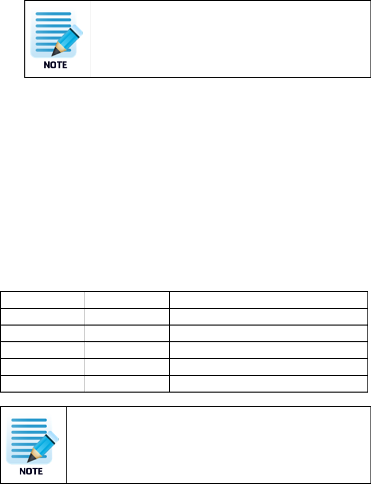
All custom channels are identified by a letter followed by a number. The letters can be
any of the following:
Channel letter: Channel ID: Channel type:
F "F" Fishing channel
L "L" Leisure channel
M "M" Yacht and leisure channels (UK only)
P "P" Private channel
W "W" Weather channel
The above custom channels must be programmed by your radio
supplier.
Page - 56 -
12.6 Volume adjustment
Function: Display screen:
Volume adjustment
1. Turn the knob to adjust the volume.
The volume symbol in the display indicates the volume level.
Ensure that you do not press the knob while adjusting the
volume.
12.7 Squelch adjustment
Function: Display screen:
Squelch adjustment
1. Press and turn the knob clockwise to reduce sensitivity.
When the knob is pressed twice, it opens the squelch
immediately.
The squelch bar appears on the screen display indicating the
current active sensitivity level. When adjusted fully to the left,
the squelch is completely open, adjusting to the right lowers
the sensitivity.
Page - 57 -
The signal strength of the current channel appears on the bar
below the squelch bar. If the received signal is strong enough,
the squelch opens and voice is received. This is indicated by the
Rx symbol.
12.8 Lock and unlock
Function: Display screen:
Lock/Unlock
1. Press and hold the HI/LO button for 2 seconds to lock or unlock the radio.
A key symbol appears when the radio is locked.
12.9 External accessories
Function: Display screen:
External accessories
Page - 58 -
The headphone symbol appears in the display screen when you connect an external
accessory, such as a headphone, microphone or external PTT.
Connector type: 3,5mm 4 pole jack.
When using an accessory, the radio is no longer waterproof.
The antenna and jack cover must be correctly assembled on the
radio in order for it to be completely waterproof, it is therefore not
recommended to use accessories while using the Tron TR30 in the
emergency mode.
12.10 Watch
When the radio is in the regular VHF mode, it can check for signals or watch in three
ways:
1. Dual watch
2. Triple watch
3. Scan
The radio will continue to watch channel 16 while receiving on other
channels.
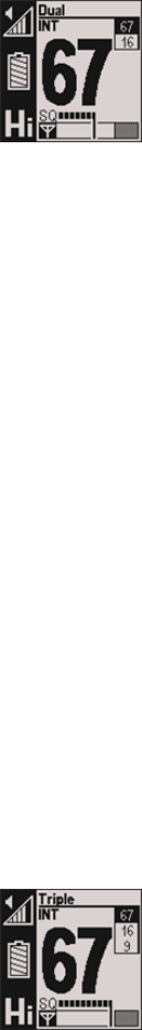
12.10.1 Dual watch
Function: Display screen:
Page - 59 -
Dual watch (DW)
The DW function allows the user to monitor channel 16 and
one selected channel alternately.
The channel search indicator is visible on the display,
however, the channels do not appear in real time.
To select DW, do the following:
1. Press the up/down arrow buttons at the same time to enter the menu.
2. Using the arrow buttons, select Settings.
3. Using the arrow buttons, select DW/TW.
4. Using the arrow buttons, select DW.
5. If the radio is not already set to DW, then select SAVE.
To activate or deactivate DW, do the following:
1. Press Scan to activate dual watch.
2. Press the up/down buttons to watch a second channel.
3. Press Scan a second time to deactive dual watch.
12.10.2 Triple watch
Function: Display:
Triple watch
The TW function allows the user to monitor channel 16 and
one selected channel alternately.
The channel search indicator is visible on the display,
Page - 60 -
however, the channels do not appear in real time.
To select TW, do the following:
1. Press the up/down arrow buttons at the same time to enter the menu.
2. Using the arrow buttons, select Settings.
3. Using the arrow buttons, select DW/TW.
4. Using the arrow buttons, select TW.
5. If the radio is not already set to TW, then select SAVE.
To activate or deactivate TW, do the following:
1. Press Scan to activate triple watch.
2. Press the up/down buttons to watch a second channel.
3. Press Scan a second time to deactive triple watch.
After choosing TW, you can turn on/off triple watch by pressing
Scan again.
Function: Display:
Call channel programming
To program a call channel, do the following:
Page - 61 -
1. Press and hold 16 for 2 seconds to enter call channel.
2. Press and hold 16 again to enter the call channel programming screen.
3. Press up/down arrow buttons to select the desired channel.
4. Press and hold Mem until you hear a beep.
The current value updates within approximately 2 seconds.
5. Press Scan to exit the programming mode.
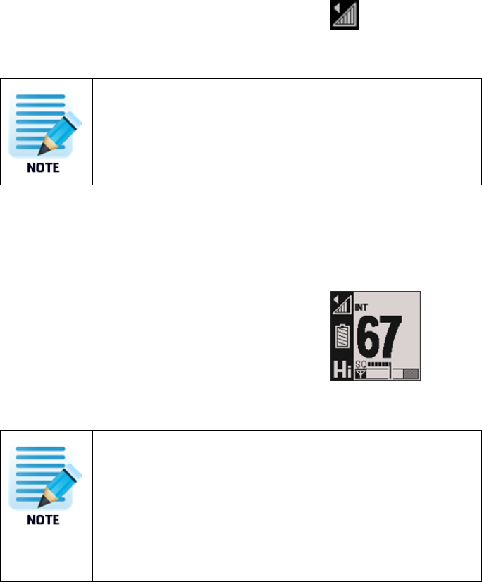
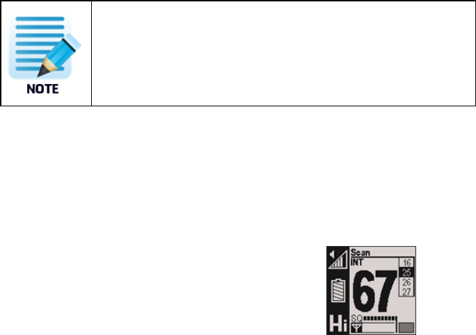
12.10.3 Scan
Function: Display screen:
Scan
All stored channels can be browsed by pressing the Mem
button. Stored channels are displayed with an M.
The channel search indicator is visible on the display,
however, the channels do not appear in real time.
The radio watches a pre-programmed set of 12 channels maximum.
To activate or deactivate Scan, do the following:
1. Press and hold Scan for 2 seconds to activate and short click to deactivate.
Page - 62 -
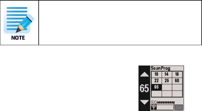
When scan is active the scan program screen opens.
Function: Display screen:
Visual method
The signal strength of the selected channel appears on the
signal strength bar.
You can store and delete memory channels for scanning in two ways, do one of the
following:
• Quick method, to be done when scan is not active.
• Visual method, to be done when scan is active.
Quick method:
1. Press the Scan button to deactivate all Scan, DW or TW functions.
2. Navigate to the channel you want to store or delete from the memory.
3. Press and hold Mem for 2 seconds to store or delete the selected channel from
memory.
Visual method:
1. Press and hold the Scan button for 2 seconds to activate Scan.
2. Press and hold the Scan button for 2 seconds again to enter the scan program
screen.
Page - 63 -
3. Use the up/down arrow buttons to select the desired channel.
4. Press and hold Mem until you hear a beep to add or remove the current channel
(wait approximately 2 seconds).
5. Press Scan to exit programming mode.
6. Press and hold Scan for 2 seconds to activate Scan.
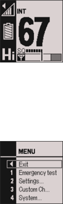
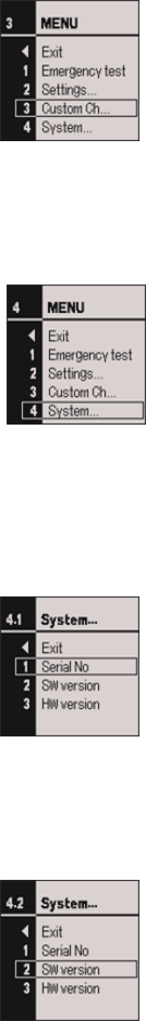
12.11 Menus
Menus: Display screen:
Press the up/down arrow buttons at the same time to enter/exit the menu system.
Use the up/down arrow buttons to navigate and select using Scan/Enter.
Exit: Display screen:
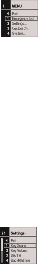
Emergency test: Display screen: Menu number:
Page - 64 -
1
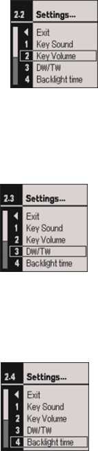
Settings: Display screen: Menu number:
Use this menu option to adjust the
following settings:
• Key sound
• Key volume
• DW/TW
• Backlight time
• Backlight level
• Contrast
• Key lock time
• Channel set
2
Key sound: Display screen: Menu number:
1
Page - 65 -
Key volume: Display screen: Menu
number:
2
DW/TW: Display screen: Menu number:
3
Backlight time: Display screen: Menu number:
4
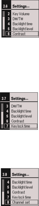
Backlight level: Display screen: Menu number:
• fff, low, high (0,1,2) 5
Page - 66 -
Contrast: Display screen: Menu number:
6
Key lock time: Display screen: Menu number:
7
Channel set: Display screen: Menu number:
8
Custom channel: Display screen: Menu number:
Page - 67 -
3
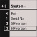
System: Display screen: Menu number:
Use this menu option to access the
following information:
• Serial Number
• SW version
• HW version
4
Serial Number: Display screen: Menu number:
1
SW Version: Display screen: Menu number:
2
Page - 68 -
HW Version: Display screen: Menu number:
3
Page - 69 -
13 Maintenance
The following maintenance should be completed.
The Tron TR30 is a sealed waterproof radio, and does not contain any
user serviceable parts inside.
This radio must never be opened by anyone other than an authorized
Jotron agent. Unauthorized disassembly will void your warranty.
13.1 Taking care of a Tron TR30
The lifetime of any equipment depends on how well you take care of it. The Tron TR30
is constructed to endure in a rough maritime environment. Regular inspection is
important to detect error symptoms and prevent potentially serious problems.
Recommended inspection tips:
• Clean the radio (externally) in fresh water only if it has been immersed in sea
water.
Ensure that the antenna and jack cover are assembled
correctly, if not the radio is not waterproof.
• Inspect the battery connection pins, the gasket and the lock/release device
regularly .
• Inspect the housing for defects regularly. This is important as defects can affect
water sealing.

Page - 70 -
13.2 Regular testing
It is important to perform regular testing of equipment to ensure proper operation,
such that you know it is in good working order in case of a potential distress situation.
Testing is completed by using the emergency test mode functionality within the radio.
To activate or deactivate the emergency test mode, do the following:
1. Select Emergency test from the menu.
2. Select ON
3. Select SAVE
4. Exit the menu to enable the mode
5. Select OFF
6. Select SAVE
7. Exit the menu to disable the mode
Testing should occur monthly if the radio is used regularly and at least once yearly
when stored on a lifeboat or raft.
Ensure you have an extra test battery available for use during testing
to avoid using a sealed lithium battery.
When testing the GMDSS radio, use the test battery included in your
purchase.
When testing the combined GMDSS and VHF Maritime radio, use the
rechargeable battery included in your purchase.
Page - 71 -
13.3 Cleaning of dirt and oil
To clean away dirt and oil from the radio wash it with warm water (no higher than 45
degrees celsius) and mild dish soap. Finish by rinsing with fresh water.

Page - 72 -
14 Test and maintenance
records
Below is an overview of all test and control details.
Date B/N/T* Signature Insp
*B=New battery, N=New Tron TR30 , T=Test.

Page - 73 -
15 Channels and frequencies
15.1 GMDSS
Channel
Number
TX/RX
(MHz)
Channel
number
TX/RX
(MHz)
Channel
number
TX/RX
(MHz)
6 156.300 14 156.700 71 156.575
8 156.400 15 156.750* 72 156.625
9 156.450 16 156.800 73 156.675
10 156.500* 17 156.850* 74 156.725
11 156.550* 67 156.375 77 156.875
12 156.600 68 156.425 87 157.375
13 156.650 69 156.475 88 157.425
* Low power mode with TX transmit power limited to 1W

Page - 74 -
15.2 International
Channel
Number
TX
(MHz)
RX
(MHz)
Channel
Number
TX
(MHz)
RX
(MHz)
Channel
number
TX
(MHz)
RX
(MHz)
1 156.050 160.650 19 156.950 161.550 68 156.425 156.425
2 156.100 160.700 20 157.000 161.600 69 156.475 156.475
3 156.150 160.750 21 157.050 161.650 71 156.575 156.575
4 156.200 160.800 22 157.100 161.700 72 156.625 156.625
5 156.250 160.850 23 157.150 161.750 73 156.675 156.675
6 156.300 156.300 24 157.200 161.800 74 156.725 156.725
7 156.350 160.950 25 157.250 161.850 77 156.875 156.875
8 156.400 156.400 26 157.300 161.900 78 156.925 161.525
9 156.450 156.450 27 157.350 161.950 79 156.975 161.575
10 156.500* 156.500 28 157.400 162.000 80 157.025 161.625
11 156.550* 156.550 60 156.025 160.625 81 157.075 161.675
12 156.600 156.600 61 156.075 160.675 82 157.125 161.675
13 156.650 156.650 62 156.125 160.725 83 157.175 161.775
14 156.700 156.700 63 156.175 160.775 84 157.225 161.825
15 156.750* 156.750 64 156.225 160.825 85 157.275 161.875
16 156.800 156.800 65 156.275 160.975 86 157.325 161.925
17 156.850* 156.850 66 156.325 160.925 87 157.375 157.375
18 156.900 161.500 67 156.375 156.375 88 157.425 157.425
* Low power mode with TX transmit power limited to 1W
Page - 75 -
16 Warranty
All Jotron products are warranted against factory defects in materials and/or
workmanship.
The warranty period for the Tron TR30 radio is valid for 2 years from the date the
product is shipped from Jotron.
During this warranty period Jotron will repair or when necessary replace a product at no
cost, including the costs of labor, materials and return transportation from Jotron or a
Jotron subsidiary (according to delivery terms: DAP Incoterms 2010 by regular freight
to "place" (airport)).
Jotron reserves the right to decide whether a defective product falls within the terms
and conditions of the warranty.
The warranty is only valid as long as service and battery replacement have been
carried out by an authorized Jotron agent or distributor. In addition, the warranty will
not apply in the instance that the product has been accidentally damaged, misused,
tampered with and/or is dysfunctional as a result of services or modifications
performed by and unauthorized person or in an unauthorized facility.
Jotron is not liable for consequential or special damages and cannot be held
responsible for any damages caused due to incorrect usage of the equipment, breach
of procedures, or the failure of any specific component or other part of the
equipment.
For product support contact: support@jotron.com
For repair requirements contact: repair@jotron.com

Page - 76 -
16.1 Warranty claims
Warranty claims can be submitted during the warranty period, all claims will be
appropriately handled according to the warranty agreement specified for this product.
Prior to returning your product for repair under a warranty claim, you must do the
following:
• Submit a warranty claim in writing to Jotron. Send a claim to: repair@jotron.com.
• If you are required to return a defective product for repair, you must attain a
return material authorization (RMA) number. Register to obtain a RMA number
under Support/RMA request at: www.jotron.com.
• Return your defective product ,your RMA number must be included as a
reference within the shipping documentation.
Service agent obligations during a warranty claim:
• Supply a replacement product from own stock, if available.
• When agreed, will return the defective product to Jotron.
• Ensure that all electronic products are shipped individually in an antistatic bag or
is covered with a Jotron plastic cover.
16.2 Service
All services such as testing, installation, programming, replacement, marking and
battery exchange are provided by an authorized Jotron service agent.
Improper service or maintenance may destroy the functionality
and/or performance of this product

Page - 77 -
Jotron does not accept any responsibility for the dismantling or
reassembling of a Tron TR30 that occurs externally from a Jotron
authorized facility and/or is handled by someone other than an
authorized, trained and certified person.
Any costs related to the above mentioned services, including
transportation connection with returning and man hours for repairing
a product will not be assumed by Jotron and must be covered by the
customer.
Jotron distributors and service agents stock the most commonly required spare parts.
16.3 Service agents
Jotron subsidiary companies:
Jotron Asia Pte. Ltd.
Changi Logistics Center
19 Loyang Way # 04-26
Singapore 508724
Tel: +65 65426350
Fax: +65 65429415
E-mail: sales@jotron.com
Jotron USA, Inc.
10645 Richmond Avenue,
Suite 170
Houston, TX 77042
USA
Tel: +1 713 268 1061
Fax: +1 713 268 1062
E-mail: sales@jotron.com
Jotron UK Ltd.
Crosland Park
Cramlington
NE23 1LA
United Kingdom
Tel: +44 1670 712000
Fax: +44 1670 590265
E-mail: sales@jotron.com

Page - 78 -
17 Optional accessories
Below is a list of additional optional accessories available for the Tron TR30 , both the
GMDSS and Maritime VHF radios.
Part Number: Part Name: 83446 87950
81341 Speaker microphone X X
83426 Test battery (orange) X
89449 Carry case X X
31030 Headset X X

Page - 79 -
18 Spare parts
Keep the original packaging. If the Tron TR30 needs to be shipped for servicing, it is
required to be shipped within the same packaging as when the product was first
received.
Part Number: Part Name: 83446 87950
83427 Antenna kit (including cover for jack plug) X X
83428 Belt clip and wrist strap kit X X
87685 RCH-30 Battery charger X
87086 Emergency GMDSS battery (orange) X X
87087 Rechargeable LiPo 1550mAh battery
(black)
X
89502 Switching power supply 100-240V/18V-
0.83A
X
Ensure that all spare parts being fitted to the Tron TR30 are original
spare parts manufactured or approved by Jotron.
Any use of counterfeit spare parts will deviate from the product type
approval certificates.
Page - 80 -
19 Recycling and disposal
The Tron TR30 is not to be disposed as normal waste and must be handled in
accordance with the applicable federal, state and local waste disposal regulations in
the country where the equipment is used.
Page - 81 -
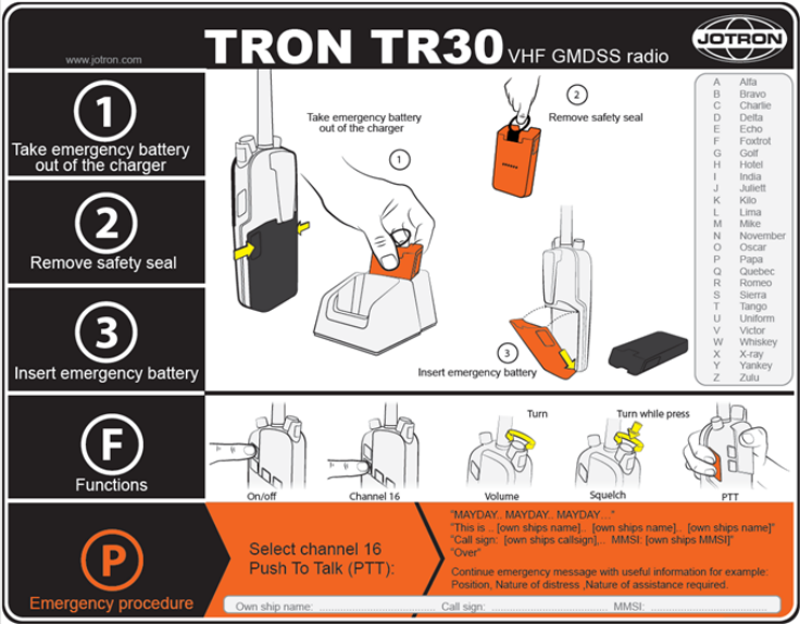
20 Emergency instructions
This is an overview of how to operate a Tron TR30 during an emergency.
Figure 5 Emergency instructions overview

www.jotron.com
Tron TR30 - v.A