Jvc Ca Vsdt6R Users Manual VS DT6 9R(B)_EN
VS-DT6R VS-DT6R, VS-DT7R, VS-DT9R LVT0853-009B English,
VS-DT9R VS-DT9R LVT0853-009B English,
VS-DT7R VS-DT7R LVT0853-009B English,
CA-VSDT9R to the manual 94bc35e7-152d-4189-83a2-3de3fe1c66ca
2015-01-26
: Jvc Jvc-Ca-Vsdt6R-Users-Manual-325563 jvc-ca-vsdt6r-users-manual-325563 jvc pdf
Open the PDF directly: View PDF ![]() .
.
Page Count: 32
COMPACT COMPONENT SYSTEM
For Customer Use:
Enter below the Model No. and Serial No.
which are located either on the rear, bot-
tom or side of the cabinet. Retain this
information for future reference.
Model No.
Serial No.
INSTRUCTIONS
LVT0853-009B
[B]
VS-DT6R/VS-DT7R/VS-DT9R
Consists of CA-VSDT6R and SP-VSDT6
Consists of CA-VSDT7R and SP-VSDT6
Consists of CA-VSDT9R and SP-VSDT9
COMPACT COMPONENT SYSTEM
COMPACT COMPONENT SYSTEM
STANDBY/ON
PLAY MODE
REPEAT
FM MODE
TREBLEBASS
SET
CANCEL
SLEEPDIMMER
DISPLAYAHB PRO
DISPLAY
MODE
FM/AM
PTY
SEARCH
PTY
SELECT
TA/NEWS
/INFO
COLOR
CLOCK
/TIMER OPEN/
CLOSE
VOLUME
MD/AUX
123
6
9
10
10
7
45
8
+
STANDBY/ON
PLAY MODE
REPEAT
FM MODE
TREBLEBASS
SET
CANCEL
SLEEPDIMMER
DISPLAYAHB PRO
DISPLAY
MODE
FM/AM
PTY
SEARCH
PTY
SELECT
TA/NEWS
/INFO
CLOCK
/TIMER OPEN/
CLOSE
VOLUME
MD/AUX
123
6
9
10
10
7
45
8
+
CA-VSDT9R
CA-VSDT6R
CA-VSDT7R
SP-VSDT6 SP-VSDT6
SP-VSDT9 SP-VSDT9
VS-DT6-7-9R[B].book Page 1 Friday, March 15, 2002 6:42 PM
G-1
Warnings, Cautions and Others
IMPORTANT for the U.K.
DO NOT cut off the mains plug from this equipment. If the plug
fitted is not suitable for the power points in your home or the
cable is too short to reach a power point, then obtain an appro-
priate safety approved extension lead or consult your dealer.
BE SURE to replace the fuse only with an identical approved
type, as originally fitted.
If nontheless the mains plug is cut off ensure to remove the fuse
and dispose of the plug immediately, to avoid a possible shock
hazard by inadvertent connection to the mains supply.
If this product is not supplied fitted with a mains plug then follow
the instructions given below:
IMPORTANT:
DO NOT make any connection to the terminal which is marked
with the letter E or by the safety earth symbol or coloured green
or green-and-yellow.
The wires in the mains lead on this product are coloured in
accordance with the following code:
Blue :Neutral
Brown :Live
As these colours may not correspond with the coloured mark-
ings identifying the terminals in your plug proceed as follows:
The wire which is coloured blue must be connected to the termi-
nal which is marked with the letter N or coloured black.
The wire which is coloured brown must be connected to the ter-
minal which is marked with the letter L or coloured red.
IF IN DOUBT - CONSULT A COMPETENT ELECTRICIAN.
Caution — %
%%
% switch!
Disconnect the mains plug to shut the power off completely (the
%
%%
% goes off).
The %
%%
% switch in any position does not disconnect the mains
line.
•When the unit is on standby, the %
%%
% lights red.
•When the unit is turned on, the operation lamps light red.
The power can be remote controlled.
CAUTION
To reduce the risk of electrical shocks, fire, etc.:
1 Do not remove screws, covers or cabinet.
2 Do not expose this appliance to rain or moisture.
IMPORTANT FOR LASER PRODUCTS
REPRODUCTION OF LABELS
1 CLASSIFICATION LABEL, PLACED ON EXTERIOR SURFACE
2 WARNING LABEL, PLACED INSIDE THE UNIT
1 CLASS 1 LASER PRODUCT
2CAUTION: Invisible laser radiation when open and inter-
lock failed or defeated. Avoid direct exposure to beam.
3CAUTION: Do not open the top cover. There are no user
serviceable parts inside the Unit; leave all servicing to qual-
ified service personnel.
CAUTION
1. Do not block the ventilation openings or holes.
(If the ventilation openings or holes are blocked by a news-
paper or cloth, etc., the heat may not be able to get out.)
2. Do not place any naked flame sources, such as lighted
candles, on the apparatus.
3. When discarding batteries, environmental problems must
be considered and local rules or laws governing the dis-
posal of these batteries must be followed strictly.
4 Do not expose this apparatus to rain, moisture, dripping or
splashing and that no objects filled with liquids, such as
vases, shall be placed on the apparatus.
Caution: Proper Ventilation
To avoid risk of electric shock and fire, and to prevent damage,
locate the apparatus as follows:
1 Top: No obstructions and open spacing.
2 Sides/ Front/ Back: No obstructions should be placed in the
areas shown by the dimensions below.
3 Bottom: Place on the level surface. Maintain an adequate
air path for ventilation by placing on a stand with a height of
10 cm or more.
CAUTION
■
■■
■About the Internal Cooling Fan
This unit includes an internal cooling fan, so as to allow for high-
power operation within a small space.
This fan comes on when the sound level is set high, and may
also come on even at low sound levels if the internal temperature
rises. To ensure effective fan operation, please leave at least
1 cm clearance on each side of the unit.
CLASS 1
LASER PRODUCT
CAUTION: Invisible laser
radiation when open and
interlock failed or defeated.
AVOID DIRECT EXPOSURE
TO BEAM. (e)
ADVARSEL: Usynlig laser-
stråling ved åbning, når
sikkerhedsafbrydere er ude
af funktion. Undgåudsæt-
telse for stråling. (d)
VARNING: Osynlig laser-
strålning när denna del är
öppnad och spärren är
urkopplad. Betrakta ej
strålen. (s)
VARO : Avattaessa ja
suojalukitus ohitettaessa
olet alttiina näkymättö-
mälle lasersäteilylle.
Älä katso säteeseen. (f)
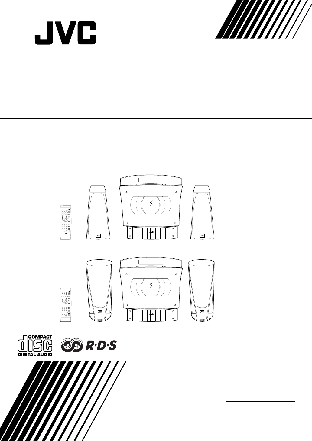
10 cm
15 cm
15 cm
15 cm
1 cm 1 cm
10 cm
15 cm
15 cm
15 cm
1 cm 1 cm
COMPACT COMPONENT SYSTEM
COMPACT COMPONENT SYSTEM
Front view
(Vertical position) (Horizontal position)
VS-DT6-7-9R[B]_Warning.fm Page 1 Tuesday, March 26, 2002 5:46 PM
G-2
SAFETY INSTRUCTIONS
“SOME DOS AND DON’TS ON THE SAFE USE OF EQUIPMENT”
This equipment has been disigned and manufactured to meet international safety standards but, like any electrical
equipment, care must be taken if you are to obtain the best results and safety is to be assured.
✮✮✮✮✮✮✮✮✮✮✮✮✮✮✮✮✮✮✮✮✮✮✮✮✮✮✮✮✮✮✮✮✮✮✮✮✮✮✮✮✮✮✮✮✮✮✮
Do read the operating instructions before you attempt to use the equipment.
Do ensure that all electrical connections (including the mains plug, extension leads and interconnections between
pieces of equipment) are properly made and in accordance with the manufacturer’s instructions. Switch off and with-
draw the mains plug when making or changing connections.
Do consult your dealer if you are ever in doubt about the installation, operation or safety of your equipment.
Do be careful with glass panels or doors on equipment.
✮✮✮✮✮✮✮✮✮✮✮✮✮✮✮✮✮✮✮✮✮✮✮✮✮✮✮✮✮✮✮✮✮✮✮✮✮✮✮✮✮✮✮✮✮✮✮
DON’T continue to operate the equipment if you are in any doubt about it working normally, or if it is damaged in any
way–switch off, withdraw the mains plug and consult your dealer.
DON’T remove any fixed cover as this may expose dangerous voltages.
DON’T leave equipment switched on when it is unattended unless it is specifically stated that it is designed for unat-
tended operation or has a standby mode.
Switch off using the switch on the equipment and make sure that your family know how to do this.
Special arrangements may need to be made for infirm or handicapped people.
DON’T use equipment such as personal stereos or radios so that you are distracted from the requirements of traffic
safety. It is illegal to watch television whilst driving.
DON’T listen to headphones at high volume as such use can permanently damage your hearing.
DON’T obstruct the ventilation of the equipment, for example with curtains or soft furnishings.
Overheating will cause damage and shorten the life of the equipment.
DON’T use makeshift stands and NEVER fix legs with wood screws — to ensure complete safety always fit the man-
ufacturer’s approved stand or legs with the fixings provided according to the instructions.
DON’T allow electrical equipment to be exposed to rain or moisture.
ABOVE ALL
— NEVER let anyone, especially children, push anything into holes, slots or any other opening in the case -
this could result in a fatal electrical shock.;
— NEVER guess or take chances with electrical equipment of any kind
— it is better to be safe than sorry!
VS-DT6-9R(B)_EN.book Page 2 Thursday, January 17, 2002 1:26 PM
1
Introduction
Thank you for purchasing the JVC Compact Component System.
We hope it will be a valued addition to your home, giving you years of enjoyment.
Be sure to read this instruction manual carefully before operating your new stereo system.
In it you will find all the information you need to set up and use the system.
If you have a query that is not answered by the manual, please contact your dealer.
Features
Here are some of the things that make your System both powerful and simple to use.
■With the slot-loading CD mechanism, you can choose to place the System either vertically or horizontally.
■The controls and operations have been redesigned to make them very easy to use, freeing you to
just enjoy the music.
• With JVC’s COMPU PLAY you can turn on the System and automatically start the Radio or
CD Player with a single touch.
■The System incorporates Active Hyper Bass PRO circuitry to faithfully reproduce low frequency sounds.
■A 45-station preset capability (30 FM and 15 AM (MW/LW)) in addition to auto-seek and manual tuning.
■CD options that include repeat, random and program play.
■Timer functions; Daily Timer and Sleep Timer.
■The System is compatible with RDS (Radio Data System) broadcasting.
• The Enahanced Other Networks data enables you to standby for desired information.
• The PTY Search function searches for programmes in the category you wish.
In addition, Radio Text can be displayed using data sent by station.
■You can connect various external units, such as an MD recorder.
■The system can play CD-R and CD-RW after they have been finalized.
■You can play back your original CD-R or CD-RW recorded in Music CD format. (However they may not be played back
depending on their characteristics or recording conditions.)
How This Manual Is Organized
• Basic information that is the same for many different functions - e.g. setting the volume - is given in the section
‘Basic Operations’, and not repeated under each function.
• The names of buttons/controls and display messages are written in all capital letters: e.g. FM/AM, “CD NO DISC”.
• System functions are written with an initial capital letter only: e.g. Normal Play.
Use the table of contents to look up specific information you require.
We have enjoyed making this manual for you, and hope it serves you in enjoying the many features built into your System.
WARNINGS
•DO NOT PUT ANYTHING ON THE PANEL. IF THE SYSTEM IS OPERATED WITH SOMETHING PUT
ON THE PANEL, IT WILL BE DAMAGED WHEN YOU TRY TO OPEN THE PANEL.
•SUPPLIED SPEAKERS ARE EXCLUSIVELY FOR THIS SYSTEM. USING WITH OTHER DEVICES WILL
DAMAGE THE SPEAKERS.
IMPORTANT CAUTIONS
1Installation of the System
• Select a place which is level, dry and neither too hot nor too cold. (Between 5°C and 35°C or 41°F and 95°F.)
• Leave sufficient distance between the System and a TV.
• Do not use the System in a place subject to vibrations.
2Power cord
• Do not handle the power cord with wet hands!
• Some power is always consumed as long as the power cord is connected to the wall outlet.
• When unplugging the System from the wall outlet, always pull the plug, not the power cord.
3Malfunctions, etc.
• There are no user serviceable parts inside. In case of system failure, unplug the power cord and consult your dealer.
• Do not insert any metallic object into the System.
• Do not insert your hand between the Panel and the main body when the Panel is being closed.
VS-DT6-9R(B)_EN.book Page 1 Thursday, January 17, 2002 1:26 PM

2
Table of Contents
Introduction ........................................................................................................ 1
Features ...................................................................................................................................... 1
How This Manual Is Organized .................................................................................................1
WARNINGS .............................................................................................................................. 1
IMPORTANT CAUTIONS .......................................................................................................1
Getting Started ................................................................................................... 3
Accessories................................................................................................................................. 3
How To Put Batteries In the Remote Control ............................................................................ 3
Connecting the FM Antenna ...................................................................................................... 4
Connecting the AM (MW/LW) Antenna ................................................................................... 5
Connecting the Speakers ............................................................................................................ 6
Connecting a Subwoofer ............................................................................................................ 7
Connecting External Equipment ................................................................................................7
Connecting an MD Recorder, etc (Digital Output) ....................................................................8
Connecting the AC Power Cord................................................................................................. 8
Installing the Unit on the Stand.................................................................................................. 8
Installing the Equipment on the Wall......................................................................................... 9
Changing the Display and Control Buttons Settings................................................................ 10
Using the Remote Control........................................................................................................11
COMPU Play............................................................................................................................ 11
Basic Operations ............................................................................................. 12
Turning the Power On and Off................................................................................................. 12
Adjusting the Brightness (DIMMER)...................................................................................... 12
Changing the Color (COLOR) (VS-DT9R only)..................................................................... 13
Adjusting the Volume .............................................................................................................. 13
Reinforcing the Bass Sound (AHB PRO) ................................................................................ 14
Tone Control (BASS/TREBLE)............................................................................................... 14
Showing the Time (DISPLAY)................................................................................................ 14
Using the Tuner................................................................................................ 15
Tuning In a Station................................................................................................................... 15
Presetting Stations.................................................................................................................... 16
To Change the FM Reception Mode ........................................................................................17
Receiving FM Stations with RDS ............................................................................................17
Using the CD Player......................................................................................... 20
To Insert a CD .......................................................................................................................... 20
To Unload a CD ....................................................................................................................... 21
Basics of Using the CD Player — Normal Play.......................................................................21
Programming the Playing Order of the Tracks ........................................................................ 21
Random Play ............................................................................................................................ 22
Repeating Tracks...................................................................................................................... 22
Child Lock................................................................................................................................ 22
Using External Equipment .............................................................................. 23
Listening to External Equipment..............................................................................................23
Recording the System’s Source to External Equipment .......................................................... 23
Using the Timers.............................................................................................. 24
Setting the Clock ...................................................................................................................... 24
Setting the Daily Timer............................................................................................................ 25
Setting the SLEEP Timer .........................................................................................................26
Care And Maintenance .................................................................................... 27
Troubleshooting............................................................................................... 28
Specifications....................................................................................Back cover
VS-DT6-9R(B)_EN.book Page 2 Thursday, January 17, 2002 1:26 PM

3
Getting Started
Accessories
Make sure that you have all of the following items, which are supplied with the System.
Power Cord (1)
AM Loop Antenna (1)
Remote Control (1)
Batteries (2)
FM Wire Antenna (1)
Speaker Cords (2)
Stand (1) (for Center Unit)
Legs (2) (for Stand)
Screw (1) (for Stand)
Paper Pattern (1)
If any of these items are missing, contact your dealer immediately.
How To Put Batteries In the Remote Control
Match the polarity (+ and –) on the batteries with the + and – markings in the battery compartment.
CAUTION:
•Handle batteries properly.
■To avoid battery leakage or explosion:
• Remove batteries when the Remote Control will not be used for a long time.
• When you need to replace the batteries, replace both batteries at the same time with new ones.
• Do not use an old battery with a new one.
• Do not use different types of batteries together.
R6P(SUM-3)/AA(15F)
VS-DT6-9R(B)_EN.book Page 3 Thursday, January 17, 2002 1:26 PM
4
Getting Started
CAUTION:
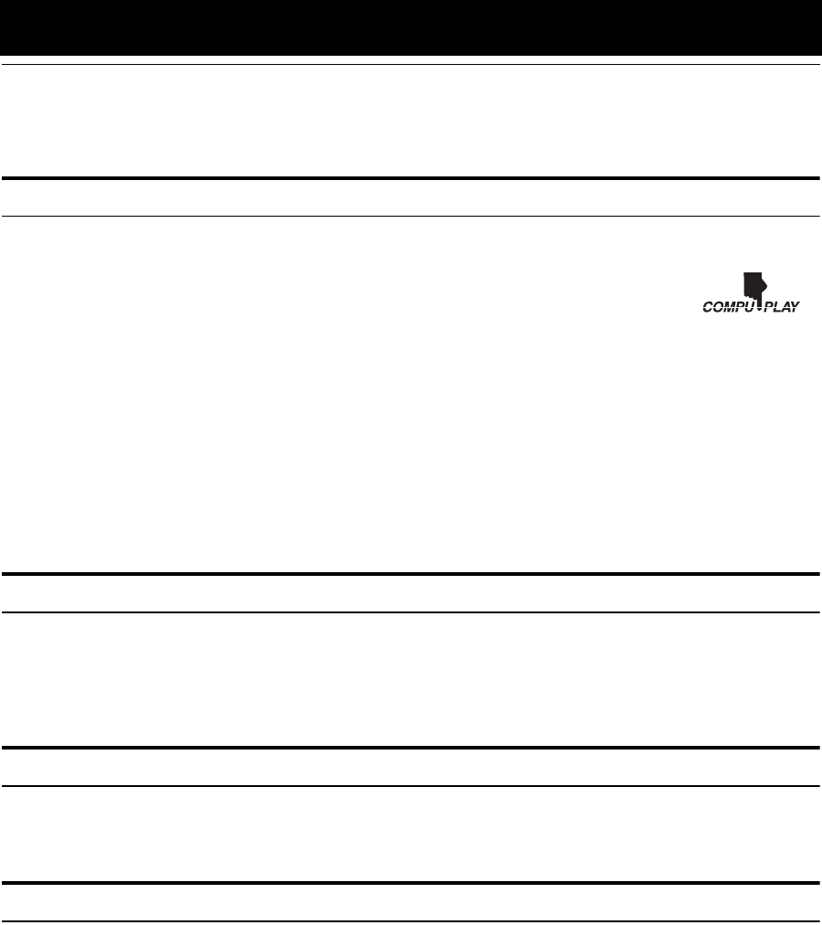
•Make all connections before plugging the System into an AC power outlet.
(Only if you install the Center Unit vertically)
• To place the Center Unit vertically, the Stand and Legs must be
attached. (See page 8.) To make connections, let the cords pass in
the holes of the Stand as shown in the diagram before attaching the
Stand and Legs.
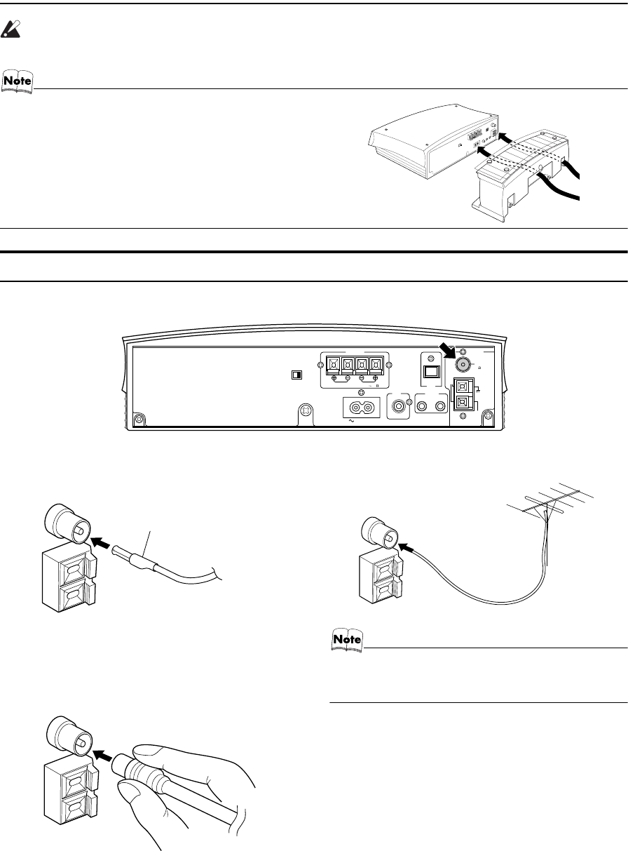
Connecting the FM Antenna
Rear Panel of the Center Unit
Using the Supplied Wire Antenna
Using the Coaxial Type Connector
(Not Supplied)
A 75 Ω antenna with coaxial type connector (IEC or DIN45
325) should be connected to the FM 75 Ω COAXIAL termi-
nal.
If reception is poor, connect the outdoor antenna.
• Before attaching a 75 Ω coaxial lead (the kind with a
round wire going to an outdoor antenna), disconnect the
supplied FM Wire Antenna.
ANTENNA
OUT IN
SPEAKERS
AC IN
SPEAKER IMPEDANCE 4 16
AM
EXT
FM
(75 )
COAXIAL
AM
LOOP
RL
MD/AUX
SUB
WOOFER
CD DIGITAL
OUT
HV
DISP.SET
FM wire antenna (supplied)
Coaxial cable
FM outdoor
antenna
(Not supplied)
VS-DT6-9R(B)_EN.book Page 4 Thursday, January 17, 2002 1:26 PM
5
Getting Started
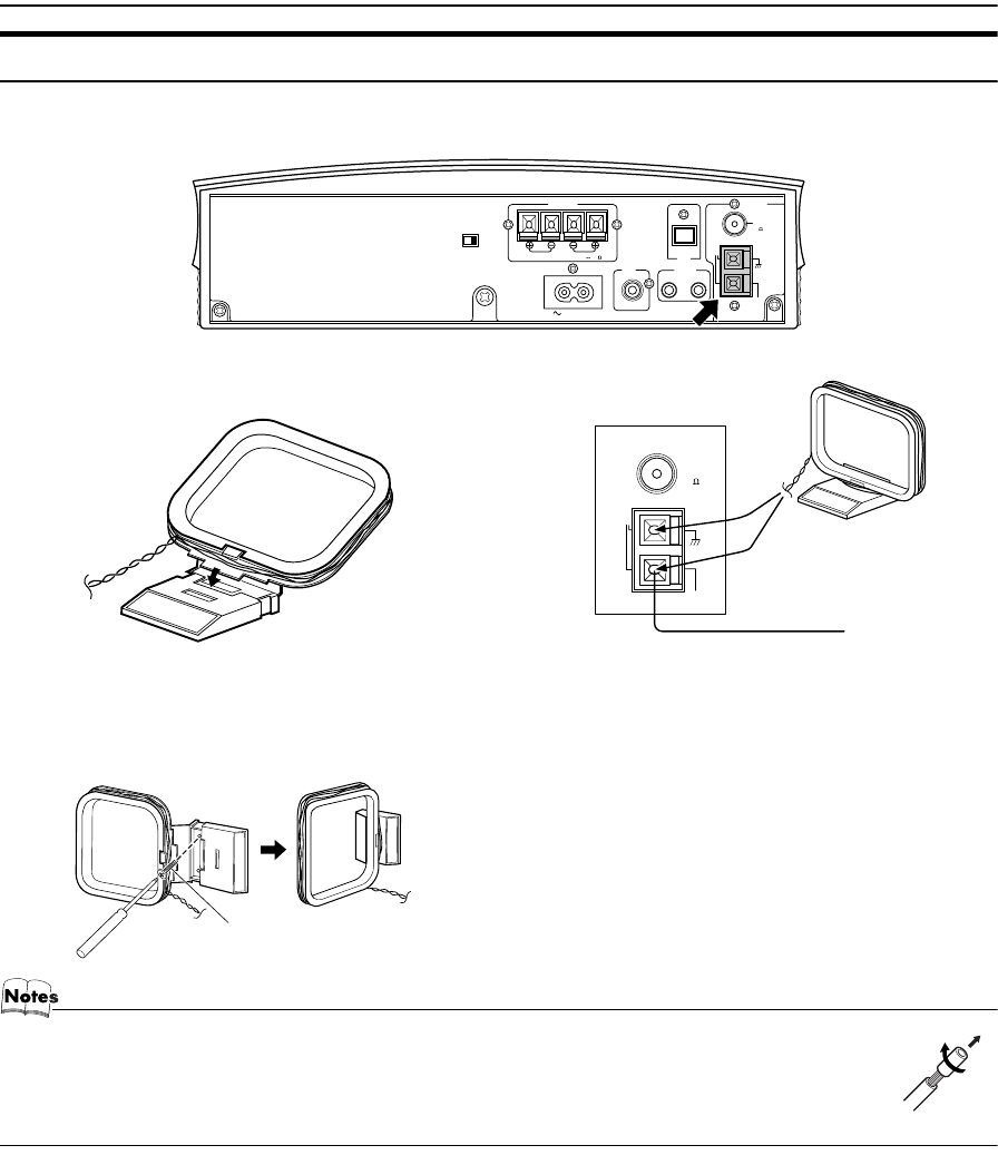
Connecting the AM (MW/LW) Antenna
Rear Panel of the Center Unit
•The AM loop antenna can be attached to a wall.
• If the AM loop antenna wire is covered with vinyl, remove the vinyl by twisting it as shown in the diagram.
• Make sure the antenna conductors do not touch any other terminals, connecting cords and power cord.
This could cause poor reception.
• If reception is poor, connect an outdoor single vinyl-covered wire to the AM EXT terminal. (Keep the AM loop
antenna connected.)
ANTENNA
OUT IN
SPEAKERS
AC IN
AM
EXT
FM
(75 )
COAXIAL
AM
LOOP
RL
MD/AUX
SUB
WOOFER
CD DIGITAL
OUT
HV
DISP.SET SPEAKER IMPEDANCE 4 16
Attach the AM loop to its base by snapping the tabs on
the loop into the slot in the base.
AM loop antenna (Supplied)
AM
EXT
FM
(75 )
COAXIAL
AM
LOOP
ANTENNA
Turn the loop until you have the best reception.
Outdoor single vinyl-
covered wire
(not supplied)
Screw (not supplied)
VS-DT6-9R(B)_EN.book Page 5 Thursday, January 17, 2002 1:26 PM
6
Getting Started
CAUTION:
•Make all connections before plugging the System into an AC power outlet.
•Handling the speakers
As this is a precision instrument, handle it carefully so as to protect it from shocks.
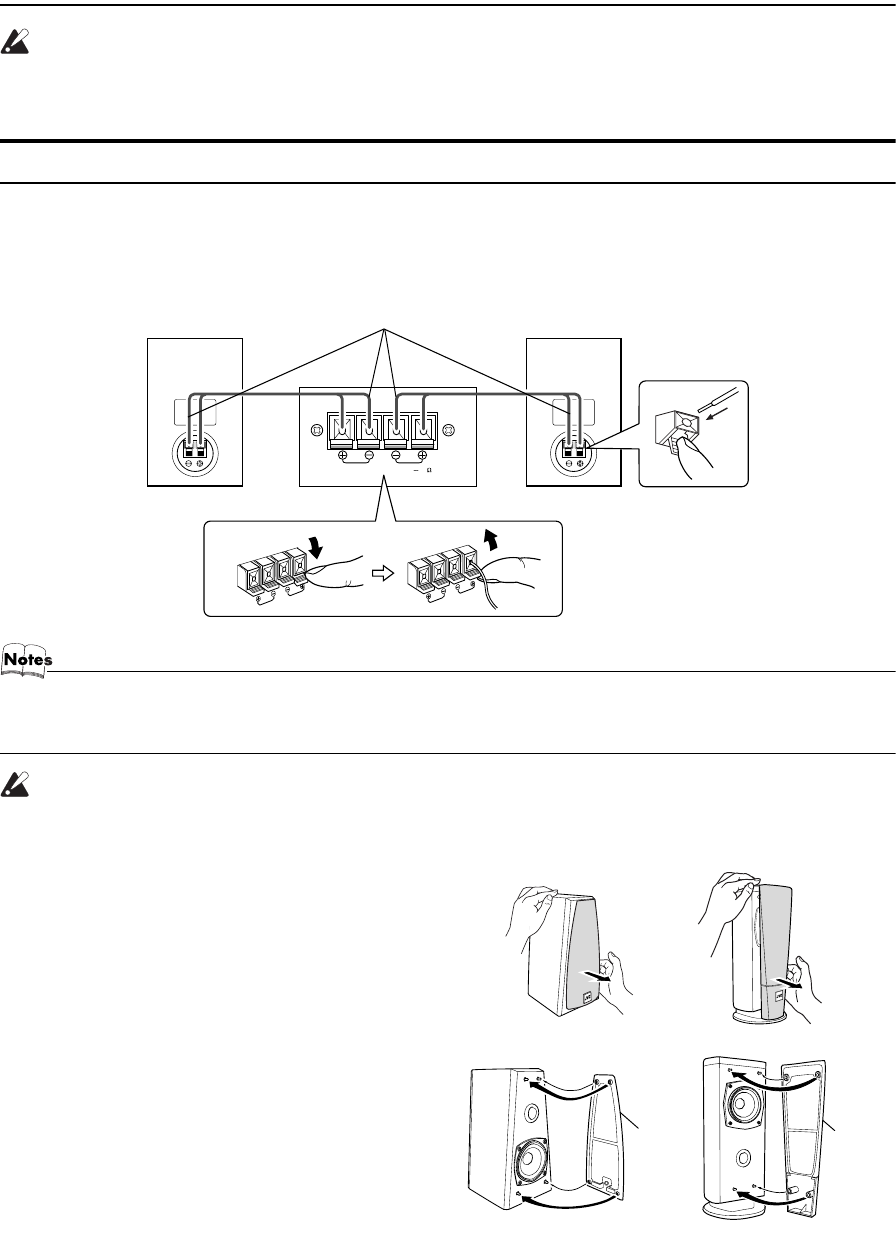
Connecting the Speakers
These speakers are exclusively for this system. Using with other devices will damege the speakers.
1. Open each of the terminals to connect the speaker wire leads.
2. Connect the speaker cords between the Speaker terminals of the Unit and the terminals of the Speakers.
Connect the cords with a black line to the (–) terminals and cords without a black line to the (+) terminals.
3. Close each of the terminals to securely connect the cords.
• Since both speakers are the same, you can put either one to the right or left side.
• Do not connect other speakers to the Unit. The difference of the load impedance causes failures.
• Do not use the supplied speakers in parallel with other speakers.
CAUTION:
•Although the speaker SP-VSDT9 has internal magnetic shielding, a TV may display irregular
colors if located near the speakers. If this happens, set the speakers away from the TV.
Removing the speaker grilles
The speaker grilles can be removed.
When removing:
1. Pull the bottom towards you with your fingers.
2. Also pull the top towords you.
When attaching the speaker grilles:
Attach the speaker grilles as shown in the diagram.
SPEAKER IMPEDANCE 4 16
SPEAKERS
RL
Right side (rear view) Left side (rear view)Marked with a black line
Speaker
grille
(SP-VSDT6) (SP-VSDT9)
Speaker
grille
(SP-VSDT6) (SP-VSDT9)
VS-DT6-9R(B)_EN.book Page 6 Thursday, January 17, 2002 1:26 PM
7
Getting Started
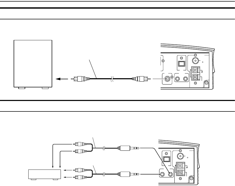
Connecting a Subwoofer
Connect a signal cord (not supplied) between the System’s SUBWOOFER terminal and the input terminal of an external sub-
woofer.
Connecting External Equipment
Connect signal cords (not supplied) between the System’s MD/AUX-OUT/IN terminals and the output/input terminals of the
external MD recorder, tape deck, etc.
You can then listen to the external source through the System or record the System’s CD player or tuner to the external unit.
ANTENNA
OUT IN
AM
EXT
FM
(75 )
COAXIAL
AM
LOOP
MD/AUX
SUB
WOOFER
CD DIGITAL
OUT
Subwoofer (not suipplied)
Signal cord (not supplied)
ANTENNA
OUT IN
AM
EXT
FM
(75 )
COAXIAL
AM
LOOP
MD/AUX
CD DIGITAL
OUT
Signal cord (not supplied)
MD recorder or tape deck
(not supplied)
Pin-plug x 2
Pin-plug x 2
Signal cord (not supplied)
Stereo mini-plug
Stereo mini-plug
VS-DT6-9R(B)_EN.book Page 7 Thursday, January 17, 2002 1:26 PM

8
Getting Started
Connecting an MD Recorder, etc (Digital Output)
Remove the cap and connect an optical digital cord (not supplied) between the System’s CD DIGITAL OUT terminal and the
input terminal of the MD recorder, etc.
You can record the digital output signal from the System’s CD Player to the MD recorder, etc.
Connecting the AC Power Cord
Firmly insert the supplied AC power cord into the AC inlet on the back of the Unit.
CAUTIONS:
•ONLY USE THE JVC POWER CORD PROVIDED WITH THIS SYSTEM
TO AVOID MALFUNCTION OR DAMAGE TO THE SYSTEM.
•BE SURE TO UNPLUG THE POWER CORD FROM THE OUTLET
WHEN GOING OUT OR WHEN THE SYSTEM IS NOT IN USE FOR AN
EXTENDED PERIOD OF TIME.
Installing the Unit on the Stand
You can place the Unit vertically by attaching the supplied Stand.
• Avoid an unstable place when placing the Unit vertically. Select a place on the level surface.
Attach the Stand to the Unit and tighten the screw. Attach the Legs to the Stand.
CD DIGITAL
OUT
MD recorder, etc. (not supplied)
Optical digital cord (not supplied)
Cap
AC IN
Power cord
Screw (supplied)
Stand (supplied)
Legs (supplied)
Back of the Leg
VS-DT6-9R(B)_EN.book Page 8 Thursday, January 17, 2002 1:26 PM
9
Getting Started
Installing the Equipment on the Wall
The Center Unit and Speakers can be attached to a wall.
CAUTIONS:
Attachment to a wall
•The Center Unit weighs approximately 4.3 kg. When its buttons are operated, an additional force will be
applied to it in the downward direction. Therefore, sufficient care must be taken when attaching to a wall
to prevent any accidents caused by the Center Unit’s falling off the wall.
•Before attaching the Center Unit to the wall, check the wall and other related aspects, and verify whether
the strength of the wall will be sufficient not only to support the weight of the Center Unit itself but also
to withstand the additional downward force which will be applied to it during operation. (Do not attach
the Center Unit to a plywood or plasterboard wall. The Center Unit may fall and sustain damage as a re-
sult.) If you do not know the strength of the wall and other aspects, consult a qualified service person
(such as a qualified constructor).
•The screws needed for attachment are not supplied. Use screws which are compatible with the strength
and material of the pillar or wall.
•When attaching the Center Unit, the screws must be secured tightly in all three locations. Attaching the
Center Unit to the wall by making only one or two holes for the screws makes for an unstable attachment
and causes a safety hazard as the Center Unit may fall down.
Location of attachment to a wall
•Care is required in selecting a location for attaching the Center Unit to the wall. Injury to personnel, or
damage to the Center Unit, may result if the Center Unit is attached in a location which interferes with
daily activities or a location that the users are liable to knock their bodies or heads against.
•Avoid a location above a bed, sofa, water tank, sink, etc. or in a passage.
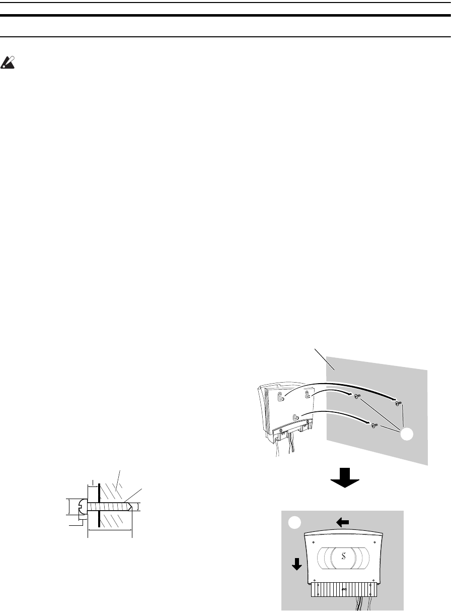
Example of attachment (Center Unit)
The procedure below is intended merely to illustrate how the
Center Unit can be attached to a wall and does not make any
guarantees for safety while using the Center Unit on a wall.
Take into account such factors as the material and strength of
the wall, the status of the reinforcing material, and the possible
changes that will take place over time.
• The cords must be connected to the Center Unit before
attaching to a wall. (See page 4.)
1. Select the place where the Center Unit is to be attached.
2. Mount three screws (not supplied) on the wall. (See the dia-
gram below for the details of the size.)
• The supplied paper pattern will assist in determining the
positions of the screws.
3. Hook the Center Unit onto the attached screws.
4. Slide the Center Unit to the side, and secure it.
• Adjust the screws if the Center Unit is not attached firmly.
COMPACT COMPONENT SYSTEM
4
1
2
3
Slide to left, then down.
6 - 9 mm
6 - 7 mm
3 mm
20 - 30 mm
Within 3 mm
Screw (not supplied)
Wall
VS-DT6-7-9R[B].book Page 9 Friday, March 15, 2002 6:42 PM
10
Getting Started
• Do not place anything on top of the Center Unit. Doing so may cause the Center Unit to fall, causing malfunctioning and/or injury.
• Do not climb onto the Center Unit or hang from it. Doing so may damage the Center Unit and/or cause injury. Special care
must be taken in this respect when there are small children in the home.
• Avoid sandwiching the cords between the Center Unit and wall. This may upset the Center Unit’s balance, causing the Center
Unit to fall.
• Make sure that the cords will not interfere with daily activities and that the users will not trip over them. Do not pull the con-
nected cords with excessive force.
• Check regularly that none of the screws are loose.
• In the event that the Center Unit has fallen, turn off the power, disconnect its power plug from the power outlet, and contact
your dealer for an inspection and repairs. Continued use of the Center Unit may result in a fire or electric shocks.
• Do not place valuables (breakables) underneath the location where the Center Unit is attached. They will be damaged if the
Center Unit should fall.
• The manufacturer accepts absolutely no liability for any accidents or damage resulting from inadequate assembly or mount-
ing, insufficient strength of attachment, misuse or abuse, or natural disasters.
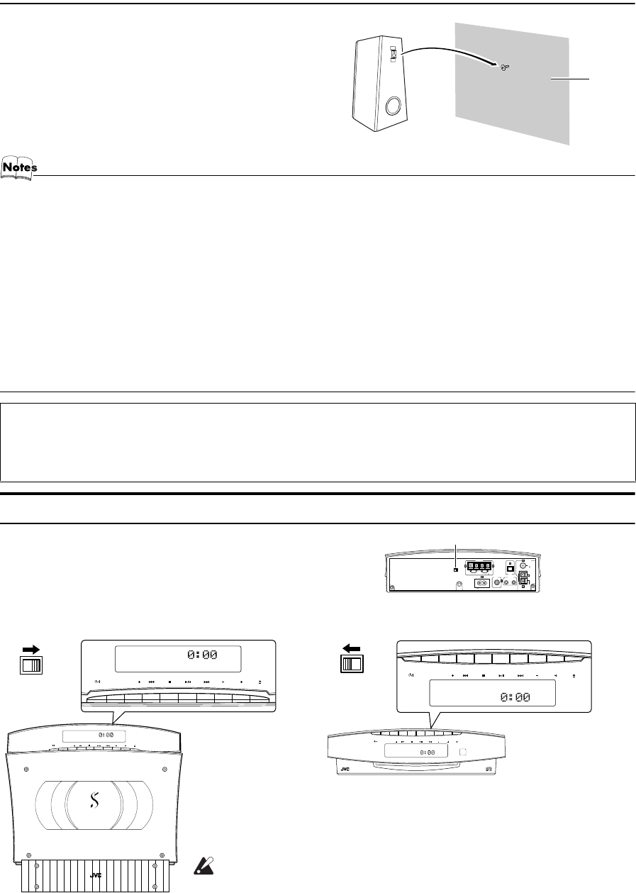
Changing the Display and Control Buttons Settings
You can change the direction of the characters and symbols on the dis-
play and the assignment of the functions to each control button on the
Unit. Change the settings depending on whether the Unit is placed ver-
tically or horizontally. The factory setting is “V”.
Example of attachment (Speakers) (SP-VSDT6 only)
The speakers can be attached to a wall.
Attach a screw (not supplied) on the wall, then hook the speaker
onto the screw.
Now you can plug the AC power cord into the wall outlet, and your System is at your
command!
Before operating, verify that the display shows the clock. If malfunctions may occur, re-
connect the power cord.
When the Unit is placed vertically
Set the DISP.SET switch to “V”.
When the Unit is placed horizontally
Set the DISP.SET switch to “H”.
Wall
ANTENNA
OUT IN
SPEAKERS
SPEAKER IMPEDANCE 4 16
AC IN
AM
EXT
FM
(75 )
COAXIAL
AM
LOOP
RL
MD/AUX
SUB
WOOFER
CD DIGITAL
OUT
HV
DISP.SET
DISP.SET
SOURCE PRESET VOL
COMPACT COMPONENT SYSTEM
SOURCE PRESET VOL
HV
DISP.SET
COMPACT COMPONENT SYSTEM
SOURCE PRESET VOL
SOURCE PRESET VOL
HV
DISP.SET
CAUTION:
•Be sure to turn off the System when changing the settings.
VS-DT6-9R(B)_EN.book Page 10 Thursday, January 17, 2002 1:26 PM
11
Getting Started
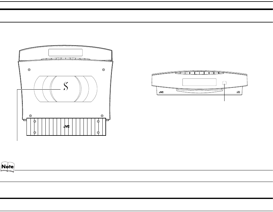
Using the Remote Control
The Remote Control makes it easy to use many of the functions of the System from a distance of up to 7 m away.
The remote sensor at which you need to point the Remote Control differs depending on whether the Unit is placed vertically
or horizontally.
• Make sure that the "DISP.SET" switch on the rear of the Unit is set correctly.
COMPU Play
JVC’s COMPU PLAY feature lets you control the most frequently used System functions with a single touch.
With One Touch Operation you can play a CD, turn on the radio, or listen to an external equipment with a single press of the
play button for that function. One Touch Operation turns the power on for you, then starts the function you have specified. If
the System is not ready (no CD in place), the System still powers on so you can insert a CD.
How One Touch Operation works in each case is explained in the section dealing with that function.
The COMPU PLAY buttons are:
On the Remote Control
3/8 button
FM/AM button
MD/AUX button
On the Unit
3/8 button
SOURCE button
•The indicators for the buttons are invisible in Standby mode.
Check the position of the buttons while the System is turned on.
COMPACT COMPONENT SYSTEM
Remote sensor (when the Unit is placed vertically)
Remote sensor (when the Unit is placed horizontally)
• The maximum operating distance becomes short when
the Panel is opened.
COMPACT COMPONENT SYSTEM
VS-DT6-9R(B)_EN.book Page 11 Thursday, January 17, 2002 1:26 PM
12
Basic Operations
Turning the Power On and Off
Turning the System On
Press the % button.
The display comes on and “HELLO” is displayed once. The
operation indicators light on the Panel. (The Panel opens
automatically if the Unit is placed vertically and the
DISP.SET switch on the rear of the Unit is set to “V”.)
The System comes on ready to continue in the mode it was
in when the power was last turned off.
■For example, if the last thing you were doing was listen-
ing to a CD, you are now ready to listen to a CD again. If
you wish, you can change to another source.
■If you were listening to the Tuner last, the Tuner comes
on playing the station it was last set to.
Turning the System Off
Press the % button again.
The Panel closes if it has been opened.
“GOOD BYE” is displayed and the display goes out, except
for the clock display. The % indicator (red) remains lit and the
rest of the operation indicators go out.
■Some power is always consumed even though power is
turned off (called Standby Mode).
■To switch off the System completely, unplug the AC
power cord from the wall outlet. When you unplug the
AC power cord, the clock will be reset to 0:00 after about
20 minutes.
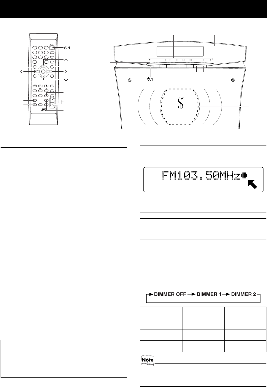
Adjusting the Brightness
(DIMMER)
(Using the Remote Control)
You can adjust the brightness of the backlighting for the dis-
play and the illumination on the cover.
When the System is Turned On
Each time you press the DIMMER button on the Remote
Control, the brightness of the backlighting and the illumina-
tion on the cover change as follows:
• When the System is turned off once, then turned on again,
the brightness setting will be restored to the previous one
since the setting is stored in memory.
SOURCE PRESET VOL
COMPACT COMPONENT SYSTEM
VOL +/–
STANDBY/ON
PLAY MODE
REPEAT
FM MODE
TREBLEBASS
SET
CANCEL
SLEEPDIMMER
DISPLAYAHB PRO
DISPLAY
MODE
FM/AM
PTY
SEARCH
PTY
SELECT
TA/NEWS
/INFO
COLOR
CLOCK
/TIMER OPEN/
CLOSE
VOLUME
MD/AUX
123
6
9
10
10
7
45
8
+
VOLUME +/–
DIMMER
TREBLE
BASS
AHB PRO
DISPLAY
COLOR
% indicator
Panel
Illumination
(VS-DT9R
only)
Operation indicators
Power Save Mode
You can reduce the power consumption in standby mode.
Press the DISPLAY button on the Remote Control when
the System is turned off.
•The clock display goes out.
CD-in indicator
While a disc is loaded on the Unit, the CD-in indicator is
lit on the display.
•The CD-in indicator lights while using the Tuner or
external equipment and does not light during CD oper-
ations.
Display Backlighting Illumination
DIMMER OFF Bright Bright
DIMMER 1 Slightly Dark Slightly Dark
DIMMER 2 Dark Off
STEREO
VS-DT6-9R(B)_EN.book Page 12 Thursday, January 17, 2002 1:26 PM
13
Basic Operations
Changing the Color (COLOR)
(VS-DT9R only)
(Using the Remote Control)
You can change the color of the illumination on the Unit.
1Press the % button to turn on the Sys-
tem.
2Press the COLOR button on the Remote
Control.
“RANDOM COLOR” is displayed.
3Press the or button to select the
setting of your choice.
The color changes as follows:
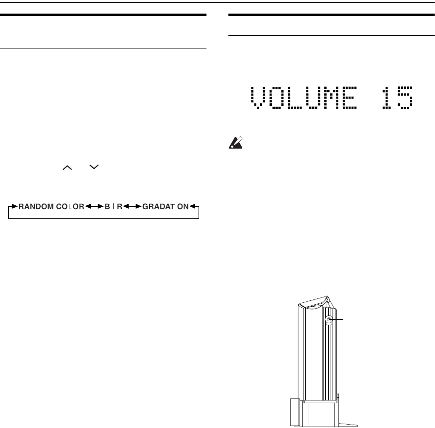
Adjusting the Volume
To increase the volume, press the VOLUME + button on the
Remote Control (or VOL + button on the Unit).
To decrease the volume, press the VOLUME – button on
the Remote Control (or VOL – button on the Unit).
You can adjust the volume level between 0 and 50.
CAUTION:
•DO NOT turn off the System with the vol-
ume set to an extremely high level; other-
wise a sudden blast of sound could
damage your hearing, speakers and/or
headphones when you turn on the System
or start playing any source next time.
REMEMBER you cannot adjust the volume
level while the System is in standby mode.
For private listening
Connect a pair of headphones to the PHONES jack. No
sound comes out of the speakers.
Be sure to turn down the volume before connecting or put-
ting on headphones.
RANDOM COLOR: The color changes randomly.
B | R:
(Blue) (Red)
The color between blue and
red is selectable in 16 steps
using the > or < button.
GRADATION: The color changes gradually
between blue and red.
(Blue) (Red)
PHONES
PHONES
VS-DT6-9R(B)_EN.book Page 13 Thursday, January 17, 2002 1:26 PM

14
Basic Operations
Reinforcing the Bass Sound
(AHB PRO)
(Using the Remote Control)
You can reinforce the bass sound to maintain rich, full bass
at low volume.
To get the effect, press the AHB (Active Hyper Bass)
PRO button.
The “AHB PRO” indicator lights up on the display.
To cancel the effect, press the button again.
The “AHB PRO” indicator goes out.
Tone Control (BASS/TREBLE)
(Using the Remote Control)
You can control the tone by changing the bass and treble.
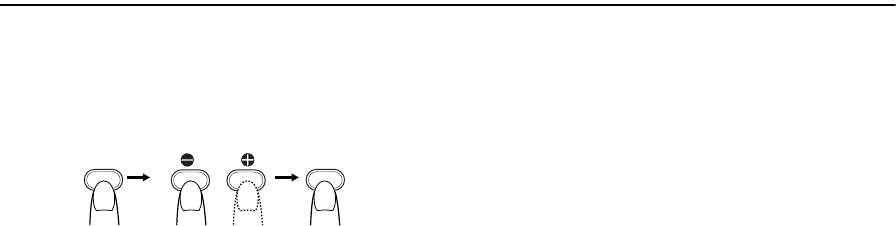
BASS Control
You can adjust the bass level (low frequency range level)
between –5 and +5. (0: Flat)
1Press the BASS button
on the Remote Control.
2Press the or button
on the Remote Control to
adjust the bass level.
TREBLE Control
You can adjust the treble level (high frequency range level)
between –5 and +5. (0: Flat)
1Press the TREBLE button
on the Remote Control.
2Press the or button
on the Remote Control to
adjust the treble level.
• Press the or button within 5 seconds to adjust the
level after pressing the BASS or TREBLE button.
Showing the Time (DISPLAY)
(Using the Remote Control)
You can show the current time on the display.
To display the clock, press the DISPLAY button on the
Remote Control.
To return to the previous mode, press the same button
again.
• To let the clock work, you need to set the clock first. (See
“Setting the Clock” on page 24.)
BASS
SET
TREBLE
SET
VS-DT6-9R(B)_EN.book Page 14 Thursday, January 17, 2002 1:26 PM
15
Using the Tuner
You can listen to FM and AM (MW/LW) stations. Stations
can be tuned in manually, automatically, or from preset
memory storage.
■Before listening to the radio:
•Make sure that both the FM and AM (MW/LW)
antennas are correctly connected. (See page 4 and 5).
One Touch Radio
Just press the FM/AM button on the Remote Control to turn
on the System and start playing the station you were last
tuned to.
■You can switch from any other sound source to the radio
by pressing the FM/AM button on the Remote Control (or
the SOURCE button on the Unit).
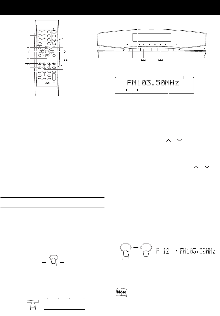
Tuning In a Station
1Press the FM/AM button.
The Band and Frequency you were last tuned to appear
on the display.
(If the last station was selected using the preset number,
the preset number appears first.)
Each time you press the button, the band alternates be-
tween FM and AM (MW/LW).
●Using the SOURCE button on the Unit
Each time you press the button, the sound source
changes.
2Select a station using one of the follow-
ing methods.
●Manual Tuning
Press the 4 or ¢ ( or ) button repeatedly to
move from frequency to frequency until you find the
station you want.
OR
●Auto Tuning
If you press and hold the 4 or ¢ ( or ) but-
ton for one second or more, the frequency changes
down, or up, automatically until a station is found.
OR
●Preset Tuning using the Remote Control
(Possible only after presetting stations)
Select the desired preset number using the Number
buttons on the Remote Control. (For the preset num-
ber more than 10, press the +10 button then the Num-
ber button.) After 1 second the display will show the
preset number’s band and frequency.
Example:
Press the +10 button then the 2 button continuously.
The preset number 12 “P12” appears.
●Preset Tuning using the Unit
Press the PRESET+ button to select the desired preset
number.
Its band and frequency are displayed.
• In AM broadcast, reception sensitivity will be changed by
turning the AM loop antenna. Turn the AM loop antenna
for best reception.
STEREO MONO RDS [TA NEWS INFO]
STANDBY/ON
PLAY MODE
REPEAT
FM MODE
TREBLEBASS
SET
CANCEL
SLEEPDIMMER
DISPLAYAHB PRO
DISPLAY
MODE
FM/AM
PTY
SEARCH
PTY
SELECT
TA/NEWS
/INFO
COLOR
CLOCK
/TIMER OPEN/
CLOSE
VOLUME
MD/AUX
123
6
9
10
10
7
45
8
+
FM MODE
PTY SELECT
TA/NEWS/INFO
PTY SEARCH
FM/AM
DISPLAY
MODE
SET
+10
Band display, Frequency display, Preset channel
FM mode indicators
* When the System is in use, the display shows other items as well.
For simplicity, we show here only the items described in this section.
RDS indicator
SOURCE PRESET VOL
SOURCE
PRESET+
Number
Buttons
FMAM
FM/AM
(on the Remote Control)
SOURCE
FM AM MD/AUX
(on the Unit)
10+ 2
(After 1 second)
VS-DT6-9R(B)_EN.book Page 15 Thursday, January 17, 2002 1:26 PM
16
Using the Tuner
Presetting Stations
(Using the Remote Control)
You can preset up to 30 FM stations and up to 15 AM (MW/
LW) stations.
• Preset numbers may have been set to factory test fre-
quencies prior to shipment. This is not a malfunction. You
can preset the stations you want into memory by following
one of the presetting methods below.
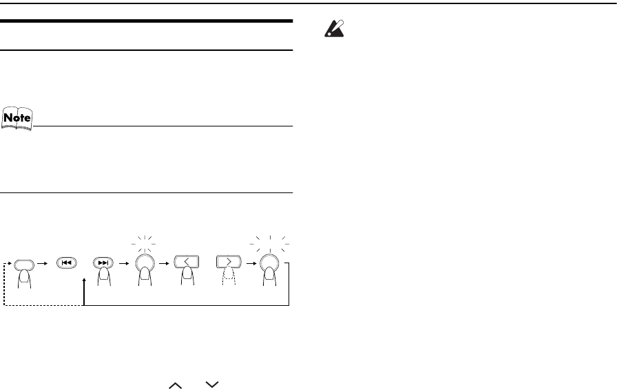
Manual Presetting
1Select a band by pressing the FM/AM
button.
2Press the 4 or ¢ ( or ) button to
tune in a station.
3Press the SET button.
“SET” will blink for 5 seconds.
Within 5 seconds, proceed to the next step.
When the display returns to the one set in step 2 after 5
seconds, press the SET button again.
4Press the > or < button within 5 seconds
to select the preset number.
> or < button: Increase or decrease the preset
number by 1.
Pressing and holding the button
will rapidly increase or decrease
the preset number.
5Press the SET button within 5 seconds.
“STORED” appears and after 2 seconds, the display re-
turns to the broadcast frequency display.
6Repeat above steps 1 to 5 for each sta-
tion you want to store in memory with a
preset number.
To change the preset stations, repeat the same
steps as above.
CAUTION:
•Even if the system is unplugged or if the
power failure occurs, the preset stations
will be stored for about 24 hours. However,
in case the preset stations are erased, you
will need to preset the stations again.
SET STORED
SETSET
FM/AM
When changing the
Band FM = 30, AM = 15
or
VS-DT6-9R(B)_EN.book Page 16 Thursday, January 17, 2002 1:26 PM

17
Using the Tuner
To Change the FM Reception
Mode
(Using the Remote Control)
When you are tuned into an FM stereo broadcast, the
“STEREO” indicator lights up and you can hear stereo ef-
fects.
If an FM stereo broadcast is hard to receive or noisy, you
can select Monaural mode. Reception improves, but you
lose stereo effect.
Press the FM MODE button on the Remote Control
so that the “MONO” indicator lights up on the dis-
play.
To restore the stereo effect, press the FM MODE button
on the Remote Control so that the “MONO” indicator goes off.
Receiving FM Stations with RDS
(Using the Remote Control)
You can use the RDS (Radio Data System) by using the Re-
mote Control.
RDS allows FM stations to send additional signals with
their regular programme signals. For example, the stations
send their station names, and information about what type
of programmes they broadcast, such as sports or music, etc.
This unit can receive the following types of RDS signals:
PS (Programme Service):
shows commonly known station names.
PTY (Programme Type):
shows types of broadcast programmes.
RT (Radio Text):
shows text messages the station sends.
What information can RDS signals provide?
The display shows RDS signal information that the station sends.
To show the RDS signals on the display
Press the DISPLAY MODE button while listening
to an FM station.
Each time you press the button, the display changes to show
information in the following order:
PS (Programme Service):
While searching, “WAIT PS” appears, then station name is
displayed. “NO PS” appears if no signal is sent.
PTY (Programme Type):
While searching, “WAIT PTY” appears, then broadcast
programme type is displayed. “NO PTY” appears if no sig-
nal is sent.
RT (Radio Text):
While searching, “WAIT RT” appears, then a text message
sent by the station is displayed. “NO RT” appears if no signal
is sent.
Station Frequency:
Station frequency (non-RDS service)
• If searching finishes at once, “WAIT PS”, “WAIT PTY” and
“WAIT RT” will not appear on the display.
• If you press the DISPLAY MODE button while listening to
an AM (MW/LW) station, the display only shows station
frequency.
• RDS is not available for AM (MW/LW) broadcasts.
MONO
FM MODE
PS PTY RT Frequency
DISPLAY
MODE
VS-DT6-9R(B)_EN.book Page 17 Thursday, January 17, 2002 1:26 PM
18
Using the Tuner
To search for a programme by PTY
codes
One of the advantages of the RDS service is that you can locate
a particular kind of programme by specifying the PTY codes.
To search for a programme using PTY or TA codes:
1Press the PTY SEARCH button once
while listening to an FM station.
“PTY SELECT” appears on the display.
2Select the PTY code using the PTY
SELECT 9 or ( button on the Remote
Control.
Each time you press the button, the display shows a cat-
egory in the following order:
None ↔ News ↔ Affairs ↔ Info ↔ Sport ↔
Educate ↔ Drama ↔ Culture ↔ Science ↔
Varied ↔ Pop M ↔ Rock M ↔ Easy M ↔
Light M ↔ Classics ↔ Other M ↔ Weather ↔
Finance ↔ Children ↔ Social ↔ Religion ↔
Phone In ↔ Travel ↔ Leisure ↔ Jazz ↔
Country ↔ Nation M ↔ Oldies ↔ Folk M ↔
Document ↔ TEST ↔ Alarm ! ↔ None
3Press the PTY SEARCH button within
10 seconds again.
While searching, the display alternates between
“SEARCH” and the selected PTY code.
The unit searched 30 preset stations and stops when it
finds a station of the category you have selected, then
tunes into that station.
To continue searching after the first stop,
press the PTY SEARCH button again while the display indi-
cations blink.
If no programme is found, “NOT FOUND” appears on the
display.
To stop searching at any time during the process,
press the PTY SEARCH button to stop search operation.
Descriptions of the PTY Codes
News: News
Affairs: Topical programme expanding on the cur-
rent news or affairs
Info: Programmes on medical service, weather
forecasts, etc.
Sport: Sports events
Educate: Educational programmes
Drama: Radio plays
Culture: Programmes on national or regional culture
Science: Programmes on natural sciences and tech-
nology
Varied: Other programmes like comedies or cere-
monies
Pop M: Pop music
Rock M: Rock music
Easy M: Middle-of-the-road music (usually called
“easy listening”)
Light M: Light music
Classics: Classical music
Other M: Other music
Weather: Weather information
Finance: Reports on commerce, trading, the Stock
Market, etc.
Children: Entertainment programmes for children
Social: Programmes on social activities
Religion: Programmes dealing with any aspect of be-
lief or faith, or the nature of existence or
ethics
Phone In: Programmes where people can express their
views either by phone or in a public forum
Travel: Programmes about travel destinations,
package tours, and travel ideas and opportu-
nities
Leisure: Programmes concerned with recreational
activities such as gardening, cooking, fish-
ing, etc.
Jazz: Jazz music
Country: Country music
Nation M: Current popular music from another nation
region, in that country’s language
Oldies: Classic pop music
Folk M: Folk music
Document: Programmes dealing with factual matters,
presented in an investigative style
TEST: Test broadcasts
Alarm !: Emergency broadcasts
None: No programmes
PTY
SELECT
PTY
SEARCH
PTY
SEARCH
VS-DT6-9R(B)_EN.book Page 18 Thursday, January 17, 2002 1:26 PM
19
Using the Tuner
To temporarily switch to a broadcast
programme of your choice
“Enhanced Other Networks” is another convenient RDS
service that allows this unit to switch temporarily to a
broadcast programme of your choice (NEWS, TA or INFO)
from the currently selected station, except if you are listen-
ing to a non-RDS station (all AM (MW/LW) stations or
some FM stations).
•If an FM station does not broadcast “Enhanced Other
Networks” information, “Enhanced Other Networks”
cannot be activated.
To select a programme type
1Press the TA/NEWS/INFO button while
listening to an FM station.
Each time you press the button, the display shows a pro-
gramme type in the following order:
TA: Traffic Announcement
NEWS: News
INFO: Programmes on medical service,
weather forecast, etc.
TA NEWS: TA or NEWS
NEWS INFO: NEWS or INFO
TA INFO: TA or INFO
TA NEWS INFO: TA, NEWS or INFO
OFF: Off
•The selected programme type indicator lights up on
the display, and the unit enters “Enhanced Other
Networks” Standby mode.
Case 1:If there is no station broadcasting the type
of programme you have selected
The broadcast station being currently heard will continue to
be heard.
«
When a station starts broadcasting the programme you have
selected, this unit automatically switches to the station. The
programme type (TA, NEWS or INFO) indicator starts
blinking.
«
When the programme is over, this unit goes back to the cur-
rently selected station, but still remains in “Enhanced Other
Networks” Standby mode.
Case 2:If there is a station broadcasting the type
of programme you have selected
This unit tunes to the station broadcasting the programme.
The programme type (TA, NEWS or INFO) indicator starts
blinking.
«
When the programme is over, this unit goes back to the cur-
rently selected station, but still remains in “Enhanced Other
Networks” Standby mode.
• If the “Enhanced Other Networks” is in standby mode and
the function (CD, MD/AUX) switch is changed or the pow-
er is switched off, then the “Enhanced Other Networks”
mode will be released. When the band is set to AM (MW/
LW), the “Enhanced Other Networks” is not activated.
When the band is set to FM again, the “Enhanced Other
Networks” will be set to standby mode.
• When the “Enhanced Other Networks” is being operated
(i.e. the selected programme type is being received from
the broadcast station) and if the DISPLAY MODE or PTY
SELECT 9 or ( button is operated, the station will not
switch back to the current selected station even after the
programme ends. The programme type indicator remains
in the display, indicating that the “Enhanced Other Net-
works” is in standby mode.
• When the alarm signal is detected by “Enhanced Other
Networks”, the station broadcasting the alarm is received
with priority. “Alarm !” is not displayed.
• When the programme type (TA, NEWS or INFO) indicator
is blinking, it is not possible to change stations.
CAUTION:
•When the sound alternated intermittently
between the station tuned in by the “En-
hanced Other Networks” function and the
current selected station, cancel the “En-
hanced Other Networks” mode. This does
not constitute malfunction of the unit.
TA NEWS INFOOFF
TA NEWS INFO TA NEWS
TA INFO NEWS INFO
VS-DT6-9R(B)_EN.book Page 19 Thursday, January 17, 2002 1:26 PM
20
Using the CD Player
You can use Normal, Random, Program or Repeat Play. Re-
peat Play can repeat all the tracks or just one of the tracks
on the CD.
Here are the basic things you need to know to play a CD and
locate the different tracks on it.
This unit has been designed to play back the following
CDs.
•CD
•CD-R
•CD-RW
When playing a CD-R or CD-RW
You can play back finalized CD-R or CD-RW record-
ed music CD format.
■You can play back CD-R or CD-RW like CD.
■Some CD-R or CD-RW may not be played back on
this unit because of their disc characteristics, damage
or stain on them, or if the player lens is dirty.
■The reflection factor of CD-RW is lower than that of
other CD, possibly causing CD-RW to take longer to
read.
The Quickest Way To Start a CD Is With the One
Touch Operation
■Press the 3¥8 button on the Remote Control.
• The power is automatically turned on. If a CD is already
inserted, it will start playing from the first track.
• If no CD is inserted, “CD NO DISC” appears on the dis-
play and the CD Player remains in Stop mode.
To Insert a CD
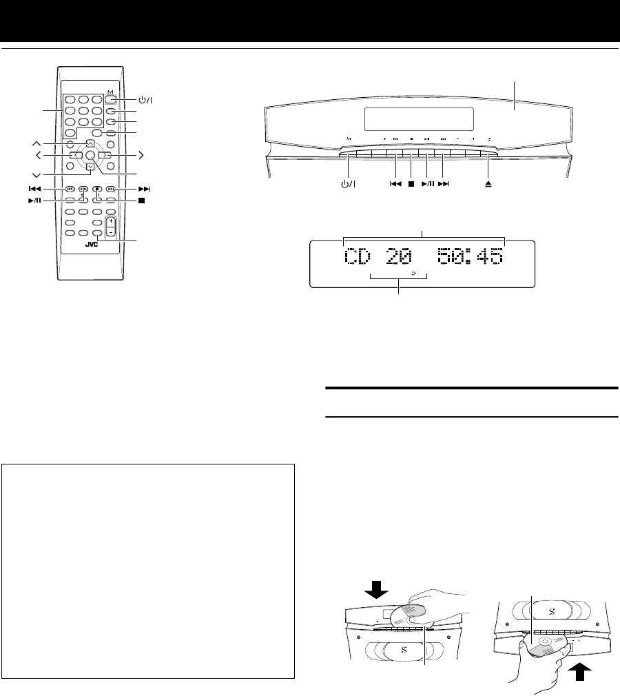
1Press the % button.
(When the Unit is placed vertically)
The Panel opens automatically.
(When the Unit is placed horizontally)
To open the Panel, press the 0 button on the Unit or the
OPEN/CLOSE button on the Remote Control.
2Insert a CD into the loading slot, with its
label side front or up as shown below.
■An 8 cm (3'') CD cannot be played back in this Unit. (Do
not attempt to insert an 8 cm (3'') CD using an adapter.
Doing so will damage the Unit.)
■If the CD cannot be read correctly (because it is scratched
or loaded upside down, for example), “CANNOT PLAY”
appears on the display.
■You can insert a CD while listening to the other source.
PROGRAM RANDOM ALL
STANDBY/ON
PLAY MODE
REPEAT
FM MODE
TREBLEBASS
SET
CANCEL
SLEEPDIMMER
DISPLAYAHB PRO
DISPLAY
MODEFM/AM
PTY
SEARCH
PTY
SELECT
TA/NEWS
/INFO
COLOR
CLOCK
/TIMER
OPEN/
CLOSE
VOLUME
MD/AUX
123
6
9
10
10
7
45
8
+
PLAY MODE
OPEN/CLOSE
REPEAT
SET
+10
Play mode indicators
Track number, Playing time, Preset number
* When the System is in use, the display shows other items as well.
For simplicity, we show here only the items described in this section.
Panel
SOURCE PRESET VOL
Number
buttons
SOURCE PRESET VOL
COMPACT COMPONENT SYSTEM
COMPACT COMPONENT SYSTEM
SOURCE PRESET VOL
Label side (when the Unit
is placed vertically)
Label side (when the Unit
is placed horizontally)
VS-DT6-7-9R[B]_2.fm Page 20 Tuesday, March 19, 2002 2:05 PM

21
Using the CD Player
CAUTIONS:
•DO NOT try to open or close the Panel by
hands as it will be damaged. Press the
OPEN/CLOSE button on the Remote Con-
trol to open or close the Panel.
•DO NOT try to insert another CD when a CD
has been already loaded on the Unit. Doing
so will damage the CDs and the Unit.
•DO NOT apply any shock to the Panel when
it is open.
•DO NOT clean the Panel when it is open.
To Unload a CD
Press the 0 button on the Unit to eject a CD. The CD is
ejected automatically, then take out the CD.
Basics of Using the CD Player
— Normal Play
To Play a CD
1Insert a CD.
2Press the 3¥8 button.
The first track of the CD begins playing.
•The CD Player automatically stops when the last
track of the CD has finished playing.
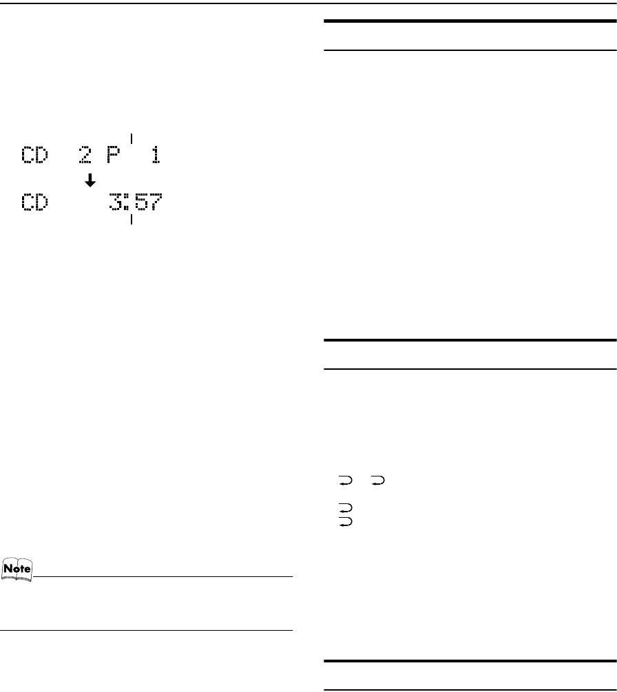
To stop playing the CD, press the 7 button.
The following information for the CD is displayed.
To stop playing and remove the CD, press the 0 but-
ton on the Unit.
To pause, press the 3¥8 button. The playback time blinks
on the display.
To cancel pause, press the same button again. Play con-
tinues from the point where it was paused.
To Select a Track or Passage within a Track
In the stop mode or during playback, press the Number but-
ton on the Remote Control to select the track you want.
•The selected track starts playing.
•For the track number more than 10, press the +10
button then the Number button.
OR
During playback, press the 4 or ¢ button to select the
track you want.
•The selected track starts playing.
•Press the ¢ button once to skip to the beginning of
the next track.
•Press the 4 button to skip to the beginning of the
track being played. Press twice quickly to skip to the
beginning of the previous track.
Search Play
Holding down the 4 or ¢ button, during playback, will
fast forward/backwards the CD so you can quickly find a
particular passage in the track you are listening to.
• The < or > and or buttons on the Remote Control
operate same as the
4
or
¢
button does.
Programming the Playing Order
of the Tracks
(Using the Remote Control)
You can program the playing order of the tracks.
■You can program up to 32 tracks in any desired order in-
cluding the same tracks.
■You can only make a program when the CD Player is
stopped.
1Insert a CD.
2Press the 3/8 button.
3Press the 7 button to stop the CD.
4Press the PLAY MODE button on the
Remote Control until the “PROGRAM”
indicator lights up.
(To be continued on the next page)
SOURCE PRESET VOL
COMPACT COMPONENT SYSTEM
COMPACT COMPONENT SYSTEM
SOURCE PRESET VOL
(when the Unit is placed
vertically)
(when the Unit is placed
horizontally)
Track number Playback time
Total track number Total playback time
PLAY MODE
PROGRAM
VS-DT6-7-9R[B].book Page 21 Friday, March 15, 2002 6:42 PM
22
Using the CD Player
5Press the Number button to select the
track to program.
Each time you press the Number button, the selected
track is added to the program.
•For the track number more than 10, press the +10
button then the Number button.
6Repeat step 5 to select the other tracks
for the program.
You can see the total playback time of programmed
tracks on the display.
7Press the 3/8 button.
The System plays the tracks in the order you have pro-
grammed them.
■You can skip to a particular program track by pressing the
4 or ¢ button during Program Play.
■To stop playing, press the 7 button once.
To confirm the programmed tracks while the CD
player is stopped, each time press the 4 or ¢ but-
ton; the tracks making up the program will successively be
displayed in the programmed order.
To exit the program mode once, while the CD Player
is stopped, press the PLAY MODE button to light off the
“PROGRAM” indicator.
• If the total playback time of the programmed tracks ex-
ceeds 99 minutes 59 seconds, “– – : – –” will appear on
the display.
To Modify the Program
Modify the contents of the program while the CD Player is
stopped.
Each time you press the CANCEL button, the last track in
the program is deleted. To add new tracks to the end of the
program, repeat above step 5.
•To delete the all tracks in the program, press the CANCEL
button for over 2 seconds.
Random Play
(Using the Remote Control)
The tracks will play in no special order when you use this
mode.
•To enter Random Play mode, stop playback first.
1Press the PLAY MODE button on the
Remote Control until the “RANDOM”
indicator lights.
2Press the 3/8 button.
The tracks are played in random order.
To skip a track during playback, press the ¢ button
to jump to the next track in the random sequence. Press the
4 button to jump back to the start of a track being played.
To exit Random Play mode, while the CD Player is
stopped, press the PLAY MODE button to light off the
“RANDOM” indicator and carry out Normal Play.
Repeating Tracks
(Using the Remote Control)
You can repeat all tracks or individual track, as many times
as you like.
Press the REPEAT button on the Remote Control.
The Repeat indicator changes with each press of the button,
as shown below.
=ALL=blank display = (back to the
beginning)
: Repeats one track.
ALL: In Normal Play mode, repeats all the tracks.
In Program Play mode, repeats all the tracks
in the program.
In Random Play mode, repeats all the tracks
in random order.
To exit Repeat mode, press the REPEAT button until the
Repeat indicator on the display goes out.
■Repeat mode remains in effect even when you change the
play mode.
Child Lock
You can prevent the unwanted CD ejection by locking.
•Before proceeding, check the position of the ¢ button
on the Unit, then turn off the System.
To Lock the CD Ejection
Hold down the ¢ button and press the % button on the
Unit.
“LOCKED” appears on the display.
To Release the Lock
Perform the same procedure when you locked.
“UNLOCKED” appears on the display.
PROGRAM
PROGRAM
Program order number
Total playback time of the programmed tracks
(After 2 seconds)
VS-DT6-9R(B)_EN.book Page 22 Thursday, January 17, 2002 1:26 PM
23
Using External Equipment
Listening to External Equipment
You can listen to external equipment such as MD recorder,
cassette deck or other auxiliary.
■First make sure that the external equipment is properly
connected to the System. (See page 7).
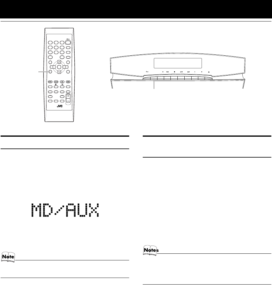
1Press the MD/AUX button.
“MD/AUX” appears on the display.
●On the Unit, press the SOURCE button until “MD/
AUX” appears on the display.
2Start playing the external equipment.
• For operation of the external equipment, refer to its In-
structions.
Recording the System’s Source
to External Equipment
You can record the System’s source to external equipment
which is connected to the MD/AUX-IN/OUT or CD DIGI-
TAL OUT terminals of the System, such as cassette deck or
MD recorder, etc.
■First make sure that the external equipment is properly
connected to the System. (See page 7).
1Play the System’s CD Player or tune in
to a station.
■The recording level is not affected by the VOLUME level
set by the System. Also it is not affected by the sound ef-
fects.
• For operation of the external equipment, refer to its In-
structions.
• While using the tuner, no signals come out from the CD
DIGITAL OUT terminal.
STANDBY/ON
PLAY MODE
REPEAT
FM MODE
TREBLEBASS
SET
CANCEL
SLEEPDIMMER
DISPLAYAHB PRO
DISPLAY
MODE
FM/AM
PTY
SEARCH
PTY
SELECT
TA/NEWS
/INFO
COLOR
CLOCK
/TIMER OPEN/
CLOSE
VOLUME
MD/AUX
123
6
9
10
10
7
45
8
+
MD/AUX
SOURCE PRESET VOL
SOURCE
VS-DT6-9R(B)_EN.book Page 23 Thursday, January 17, 2002 1:26 PM
24
Using the Timers
The timers let you control listening functions automatically.
Setting the Clock
(Using the Remote Control)
•When you plug the AC power cord into the wall outlet,
the time indication “0:00” blinks on the display.
• The clock must be correctly set for the timers to work.
1Press the %
%%
% button.
2Press the CLOCK/TIMER button on the
Remote Control.
The hour digit of the time indication rapidly blinks on
the display.
3Press the ¢ or 4 button on the
Remote Control to set the hour.
Pressing the ¢ button moves the time forwards and
pressing the 4 button moves it backwards. Hold
down the button to move the time rapidly.
4Press the SET button.
The minute digits of the time indication rapidly blink on
the display.
5Press the ¢ or 4 button to set the
minute.
6Press the SET button.
The selected time is set and the seconds start counting
from 0.
CAUTION:
•If there is a power failure, the clock loses its
setting after about 20 minutes. “0:00”
blinks on the display and the clock must be
reset.
• The clock may gain or lose one to two minutes per month.
• The or button operates same as the
¢
or
4
button does.
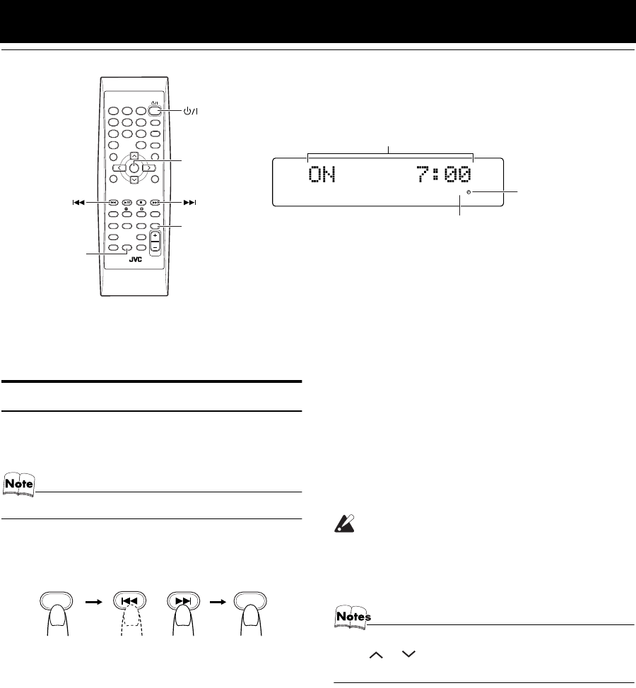
SLEEP
Timer indicator
* When the System is in use, the display shows other items as well.
For simplicity, we show here only the items described in this section.
SLEEP indicator
ON time, OFF time, Source, Volume
STANDBY/ON
PLAY MODE
REPEAT
FM MODE
TREBLEBASS
SET
CANCEL
SLEEPDIMMER
DISPLAYAHB PRO
DISPLAY
MODE
FM/AM
PTY
SEARCH
PTY
SELECT
TA/NEWS
/INFO
COLOR
CLOCK
/TIMER OPEN/
CLOSE
VOLUME
MD/AUX
123
6
9
10
10
7
45
8
+
SET
SLEEP
CLOCK
/TIMER
CLOCK
/TIMER CLOCK
/TIMER
VS-DT6-9R(B)_EN.book Page 24 Thursday, January 17, 2002 1:26 PM
25
Using the Timers
Setting the Daily Timer
(Using the Remote Control)
Once you have set the Daily Timer, the timer will be acti-
vated at the same time every day.
The Timer indicator ( ) on the display shows that the Dai-
ly Timer you have set is in effect.
•When the Timer Indicator ( ) is displayed, the timer is
activated.
•When the Timer Indicator ( ) is not displayed, the timer
is deactivated.
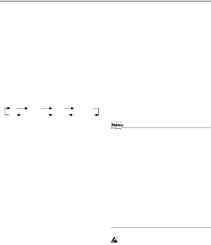
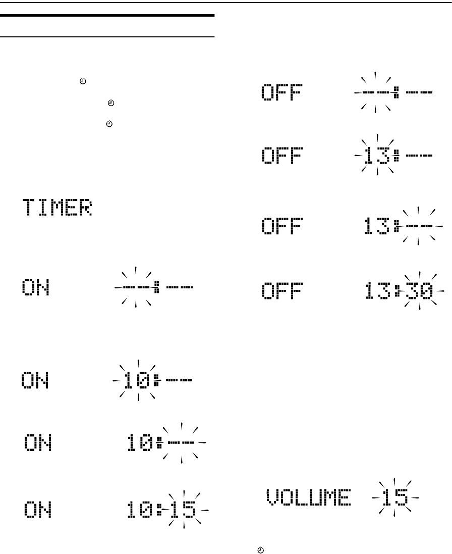
1Setting the ON time (Example: 10:15).
1. Press the CLOCK/TIMER button on the Remote
Control.
“TIMER” appears on the display.
•When the clock is not set, “0:00” appears on the dis-
play. Set the clock first.
2. Press the CLOCK/TIMER button again. The hour
digit of the “ON” time blinks on the display.
Press the ¢ or 4 button on the Remote Control
to set the hour you want the Unit to come on.
Pressing the ¢ button moves the time forwards and
pressing the 4 button moves it backwards. Hold
down the button to move the time rapidly.
3. Press the SET button.
The minute digits of the ON time blink on the display.
Set the minute you want the Unit to come on, using
the ¢ or 4 button.
2Setting the OFF time (Example: 13:30).
1. Press the SET button.
The hour digit of the OFF time blinks on the display.
(The same time as the ON time will be automatically
set.)
Set the hour you want the Unit to be turned off, using
the ¢ or 4 button.
2. Press the SET button.
The minute digits of the OFF time blink on the dis-
play.
Set the minute you want the Unit to be turned off, us-
ing the ¢ and 4 buttons.
3Selecting the music source.
1. Press the SET button.
The “TUNER” or “CD” blinks on the display.
2. Press the ¢ or 4 button to select the music
source you want to listen to.
The display changes as shown below.
TUNERÔCDÔ(back to the beginning)
4Setting the volume level.
1. Press the SET button.
The current volume setting blinks on the display.
2. Press the ¢ or 4 button to select the volume level.
-- :The current volume level will be used.
0 to 50 :When the timer is turned on, the Volume
will be automatically set to the selected
level.
5Press the SET button.
The timer setting is completed and the Timer indicator
( ) appears on the display. The display shows the
each setting of the Timer and returns to the display be-
fore you set the Timer.
(To be continued on the next page)
VS-DT6-9R(B)_EN.book Page 25 Thursday, January 17, 2002 1:26 PM
26
Using the Timers
6Before turning off the System, prepare
the music source selected in step 3.
TUNER: Tune in to the desired station.
CD: Insert a CD. (Playback will start from the first
track at Timer on.)
7Press the %
%%
% button to turn off the Sys-
tem.
In standby mode, you can see the Timer indicator ( )
on the display.
•When the timer turns on, the Timer indicator starts
blinking and the prepared source in step 6 will be
played.
To confirm the timer setting
Press the CLOCK/TIMER button, then press the SET
button. Each setting appears on the display.
To cancel the timer
Press the CLOCK/TIMER button, then press the CAN-
CEL button. The Timer
indicator ( ) goes out.
To re-activate the cancelled timer
Press the CLOCK/TIMER button, then press the SET
button.
The Timer
indicator ( ) appears.
To change the timer setting
Repeat the setting procedure from the beginning.
CAUTION:
•If the System is unplugged, or a power fail-
ure occurs, the timer setting will be lost.
You will need to reset the clock first, then
the timer.
Setting the SLEEP Timer
(Using the Remote Control)
Use the Sleep Timer to turn the System off after a certain
number of minutes when it is playing. By setting the Sleep
Timer, you can fall asleep to music and know that your Sys-
tem will turn off by itself rather than play all night.
■You can only set the Sleep Timer when the System is on
and a source is playing.
1Play a CD or tune in to the desired sta-
tion.
2Press the SLEEP button on the Remote
Control.
The “SLEEP” indicator lights up.
■When the clock is not set, “0:00” appears on the dis-
play. Set the clock at first.
3Set the length of time you want the
source to play before shutting off.
•Each time you press the SLEEP button, it changes
the number of minutes shown on the display in this
sequence:
10 = 20 = 30 = 60 = 90 = 120 = Cancelled =
(back to the beginning)
The selected number of minutes for the Sleep Timer will
disappear five seconds later and the display returns to the
original one before setting the Sleep Timer. (The display is
dimmed.)
The System is now set to turn off after the number of min-
utes you set.
To Confirm the Sleep Time:
When the SLEEP button is pressed, the remaining sleep
time is displayed. Wait until the display returns to the orig-
inal display.
To Cancel the SLEEP Timer Setting:
Press the SLEEP button until the “SLEEP” indicator goes
out on the display.
Turning off the System also cancels the SLEEP Timer.
■If you are setting the Daily Timer, the System will be
turned on at the set time to wake you up.
VS-DT6-9R(B)_EN.book Page 26 Thursday, January 17, 2002 1:26 PM
27
Care And Maintenance
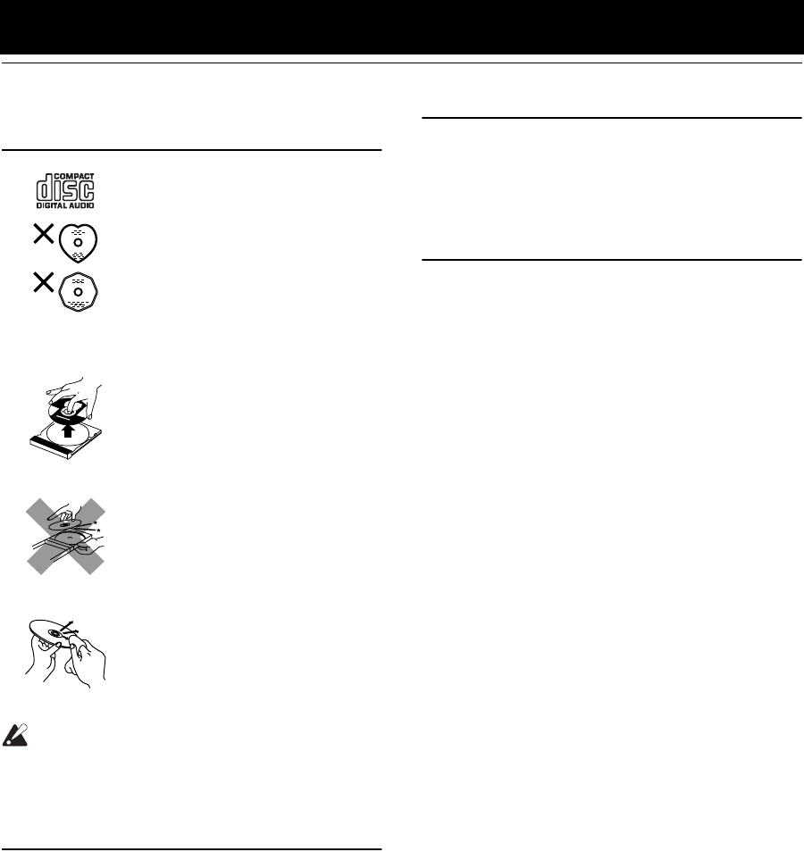
Handle your CDs carefully, and they will last a long time.
Compact Discs
CAUTION:
•Do not use any solvent (for example, con-
ventional record cleaner, spray thinner,
benzine, etc.) to clean a CD.
Moisture Condensation
Moisture may condense on the lens inside the System in the
following cases:
•After turning on heating in the room.
•In a damp room.
•If the System is brought directly from a cold to a warm
place.
Should this occur, the System may malfunction. In this
case, leave the System turned on for a few hours until the
moisture evaporates, unplug the AC power cord, and then
plug it in again.
General Notes
In general, you will have the best performance by keeping
your CDs and the mechanism clean.
•Store CDs in their cases, and keep them in cabinets or on
shelves.
•Keep the System’s Panel closed when not in use.
Cleaning the unit
•Stains on the unit
Should be wiped off with a soft cloth. If the unit is heavily
stained, wipe it with a cloth soaked in water-diluted neu-
tral detergent and wrung well, then wipe clean with a dry
cloth.
•Since the unit may deteriorate in quality, become dam-
aged or get its paint peeled off, be careful about the fol-
lowings.
- DO NOT wipe it with a hard cloth.
- DO NOT wipe it strong.
- DO NOT wipe it with thinner or benzine.
- DO NOT apply any volatile substance such as insecti-
cides to it.
- DO NOT allow any rubber or plastic to remain in con-
tact with it for a long time.
•Only CDs bearing this mark can
be used with this System. How-
ever, continued use of irregular
shape CDs (heart-shape, octago-
nal, etc.) can damage the System.
•Do not stick a paper tape or a seal
on the reading side or the label
side.
If you do so, the CD may not be
unloaded, or the System can be
damaged.
•Remove the CD from its case by
holding it at the edges while press-
ing the case’s center hole lightly.
•Do not touch the shiny surface of
the CD, or bend the CD.
•Put the CD back in its case after
use to prevent warping.
•Be careful not to scratch the sur-
face of the CD when placing it
back in the case.
•Avoid exposure to direct sunlight,
temperature extremes, and moisture.
•A dirty CD may not play cor-
rectly. If a CD does become dirty,
wipe it with a soft cloth in a
straight line from center to edge.
VS-DT6-7-9R[B].book Page 27 Friday, March 15, 2002 6:42 PM
28
Troubleshooting
•If you are having a problem with your System, check this
list for a possible solution before calling for service.
•If you cannot solve the problem from the hints given
here, or the System has been physically damaged, call a
qualified person, such as your dealer, for service.
Symptom Possible Cause Action
No sound is heard. •Connections are incorrect, or loose.
•Headphones are connected.
•Check all connections and make
corrections. (See pages 4 to 8.)
•Disconnect the headphones.
Poor radio reception •The antenna is disconnected.
•The AM Loop Antenna is too close to the
System.
•The FM Wire Antenna is not properly
extended and positioned.
•Reconnect the antenna securely.
•Change the position and direction of the
AM Loop Antenna.
•Extend FM Wire Antenna to the best
reception position.
The CD skips. The CD is dirty or scratched. Clean or replace the CD.
The CD does not play. The CD is upside down. Put the CD in with the label side up.
Unable to operate the Remote Control. •The path between the Remote Control
and the sensor on the Unit is blocked.
•The batteries have lost their charge.
•Remove the obstruction.
•Replace the batteries.
Operations are disabled. The built-in microprocessor has
malfunctioned due to external electrical
interference.
Unplug the System then plug it back in.
“CD NO DISC” appears.
There is no disc loaded.
Insert a disc.
“CANNOT PLAY” or
“UNFINALIZ”
appears.
•The CD-R or CD-RW that hasn’t yet been
finalized (including blank discs) has been
inserted.
•The disc has been inserted with its label
side down.
•Insert a CD-R or CD-RW that has been
finalized.
•Remove the disc and insert it with the
label side front or up. (See page 20.)
The characters and symbols on the display
appear upside down.
The DISP.SET switch on the rear panel of
the Center Unit has not been set correctly.
Set the DISP.SET switch correctly. (See
page 10.)
VS-DT6-7-9R[B].book Page 28 Friday, March 15, 2002 6:42 PM
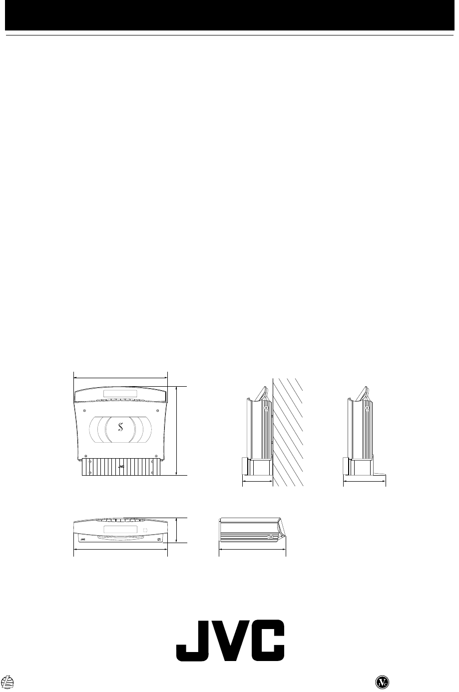
29
Specifications
Amplifier
Output Power 38 W (19 W + 19 W) at 4 Ω (Max.)
30 W (15 W + 15 W) at 4 Ω
(10 % THD)
Input Sensitivity/Impedance (1 kHz)
MD/AUX IN 500 mV/47 kΩ
Output Sensitivity/Impedance (1 kHz)
MD/AUX OUT 500 mV/5 kΩ
CD DIGITAL OUT –21 dBm - –15 dBm
(Optical out)
Speaker terminals 4 Ω- 16 Ω
Subwoofer out 440 mV/6 kΩ
Phones 16 Ω - 1 kΩ
0 - 15 mW/ch output into 32 Ω
CD Player
Signal-To-Noise Ratio 100 dB (typical)
Wow And Flutter Unmeasurable
Tuner
FM Tuner
Tuning Range 87.5 MHz - 108.0 MHz
AM Tuner
Tuning Range (MW) 522 kHz - 1 629 kHz
(LW) 144 kHz - 288 kHz
Power Specifications
Power Requirements AC 230 V ~ , 50 Hz
Power Consumption 36 W (power on mode)
2.5 W (power save mode)
Center Unit
Dimensions*
(CA-VSDT6R/CA-VSDT7R/CA-VSDT9R)
325 mm
✕
86 mm
✕
237 mm (W/H/D)
Mass*
(CA-VSDT6R/CA-VSDT7R)
Approx. 3.9 kg
(CA-VSDT9R) Approx. 4.0 kg
* without Stand and Legs
Speaker Specifications (each unit)
SP-VSDT6
Speakers 8 cm cone
Impedance 4 Ω
Dimensions 124 mm ✕ 255 mm ✕ 124 mm (W/H/D)
Mass 1.4 kg
SP-VSDT9
Speakers 8 cm cone
Impedance 4 Ω
Dimensions 125 mm ✕ 293 mm ✕ 129 mm (W/H/D)
Mass 1.4 kg
Accessories
Power Cord (1)
AM Loop Antenna (1)
Remote Control (1)
Batteries R6P (SUM-3)/AA (15F) (2)
FM Wire Antenna (1)
Speaker Cords (2)
Stand (1) (for Center Unit)
Legs (2) (for Stand)
Screw (1) (for Stand)
Paper Pattern (1)
Dimensions for Installation (CA-VSDT6R/CA-VSDT7R/CA-VSDT9R)
Design and specifications are subject to change without notice.
COMPACT COMPONENT SYSTEM
PHONESPHONES
COMPACT COMPONENT SYSTEM
PHONES
325 mm
325 mm 237 mm
301.5 mm
140 mm
86 mm
105.5 mm
Vertical Position
Horizontal Position
(On the wall) (With Legs)
VICTOR COMPANY OF JAPAN, LIMITED
0302MNMIDEJEM
EN
VS-DT6-7-9R[B]_3.fm Page 29 Wednesday, March 27, 2002 6:04 PM
