Jvc Gr Dvl9000 Instruction Manual
GR-DVL9000 - Instruction Manual GR-DVL9000-en Free User Guide for JVC Camcorder, Manual - page1
2015-08-19
: Jvc Jvc-Gr-Dvl9000-Instruction-Manual-787459 jvc-gr-dvl9000-instruction-manual-787459 jvc pdf
Open the PDF directly: View PDF ![]() .
.
Page Count: 88
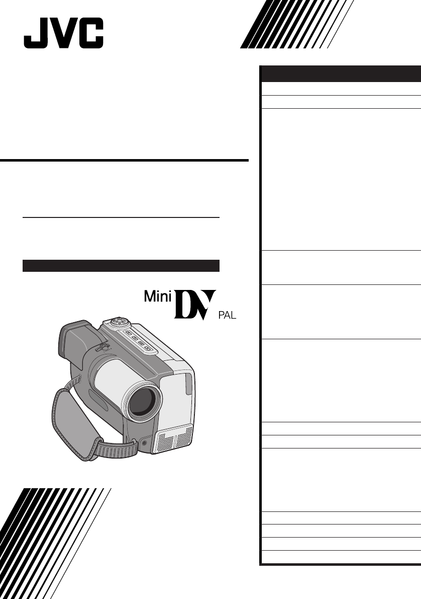
GR-DVL9000
DIGITAL VIDEO CAMERA
LYT0130-001A
INSTRUCTIONS
Please visit our CyberCam Homepage on
the World Wide Web and answer our
Consumer Survey (in English only):
http://www.jvc-victor.co.jp/index-e.html
CONTENTS
ABOUT DV
5
PROVIDED ACCESSORIES
6
GETTING STARTED
8
Charging The Battery Pack..................... 8
Installing The Battery Pack .................... 9
Indoor Use ..................................... 10
Using The Power Pack........................ 10
Date/Time Settings ........................... 11
Loading/Unloading A Cassette .............. 12
Recording Mode Setting ...................... 13
Grip Strap Attachment........................ 14
Tripod Mounting ............................... 14
Shoulder Strap Attachment .................. 15
Dioptre Adjustment ........................... 15
Remote Control Unit .......................... 16
Operation Mode ............................... 17
RECORDING
18
Basic Recording ................................ 18
Advanced Features ............................ 25
PLAYBACK
50
Basic Playback ................................. 50
Advanced Features ............................ 52
Basic Connections ............................. 56
Advanced Connections ........................ 58
EDITING
60
Dubbing ......................................... 60
Digital Dubbing ................................ 61
Brand Setting .................................. 62
Random Assemble Editing .................... 63
For More Accurate Editing .................... 66
Audio Dubbing ................................. 68
Insert Editing................................... 69
TROUBLESHOOTING
70
AFTER USE
75
CONTROLS, INDICATIONS
AND CONNECTORS
76
LCD Monitor/Viewfinder Indications
During Recording ............................ 79
LCD Monitor Indications During Playback .... 80
Warning Indications ........................... 81
CAUTIONS
82
SPECIFICATIONS
84
GLOSSARY OF TERMS
85
INDEX
86
2 EN
Connection to the mains supply in the United
Kingdom.
DO NOT cut off the mains plug from this equipment.
If the plug fitted is not suitable for the power
points in your home or the cable is too short to
reach a power point, then obtain an appropriate
safety approved extension lead or consult your
dealer.
BE SURE to replace the fuse only with an
identical approved type, as originally fitted,
and to replace the fuse cover.
If nontheless the mains plug is cut off ensure to
remove the fuse and dispose of the plug
immediately, to avoid a possible shock hazard
by inadvertent connection to the mains supply.
If this product is not supplied fitted with a mains
plug then follow the instructions given below:
DO NOT make any connection to the Larger
Terminal coded E or Green.
The wires in the mains lead are coloured in
accordance with the following code:
Blue to N (Neutral) or Black
Brown to L (Live) or Red
If these colours do not correspond with the
terminal identifications of your plug, connect as
follows:
Blue wire to terminal coded N (Neutral) or
coloured black.
Brown wire to terminal coded L (Live) or
coloured Red.
If in doubt — consult a competent electrician.
Dear Customer,
Thank you for purchasing this Digital Video Camera. Before use, please read the safety information and
precautions contained in the following pages to ensure safe use of this product.
Using This Instruction Manual
•All major sections and subsections are listed in the Table Of Contents (Z cover page).
•Notes appear after most subsections. Be sure to read these as well.
•Basic and advanced features/operation are separated for easier reference.
It is recommended that you . . .
.... refer to “Controls, Indications and Connectors”
(Z pgs. 76 – 81) and familiarize yourself with button locations, etc. before use.
.... read thoroughly the Safety Precautions that follow. They contain extremely important information
regarding the safe use of your new camcorder.
SAFETY PRECAUTIONS
You are recommended to carefully read the cautions on pages 82 and 83 before use.
Warning on lithium cell battery
The battery used in this device may present a
fire or chemical burn hazard if mistreated. Do
not recharge, disassemble, heat above 100°C or
incinerate.
Replace battery with Maxell, Panasonic
(Matsushita Electronic), Sanyo or Sony CR2025;
use of another battery may present a risk of fire
or explosion.
nDispose of used battery properly.
nKeep away from children.
nDo not disassemble and do not dispose of in
fire.
CAUTIONS:
nTo prevent shock, do not open the cabinet.
No user serviceable parts inside. Refer
servicing to qualified personnel.
nWhen you are not using the AC Power
Adapter/Battery charger for a long period of
time, it is recommended that you disconnect
the power cord from AC outlet.
WARNING:
TO PREVENT FIRE OR SHOCK
HAZARD, DO NOT EXPOSE
THIS UNIT TO RAIN OR
MOISTURE.
IMPORTANT
EN 3
This unit is produced to comply with Standard
IEC Publ. 65.
NOTES:
●
The rating plate (serial number plate) and
safety caution are on the bottom and/or the
back of the main unit.
●
The rating plate (serial number plate) of the
AC Power Adapter/Charger is on its bottom.
This camcorder is designed to be used with
PAL-type colour television signals. It cannot be
used for playback with a television of a different
standard. However, live recording and LCD
monitor/viewfinder playback are possible
anywhere. Use the BN-V814U battery pack
and, to recharge it, the provided multi-voltage
AC Power Adapter/Charger. (An appropriate
conversion adapter may be necessary to
accommodate different designs of AC outlets in
different countries.)
SOME DO’S AND
DON’TS ON THE SAFE
USE OF EQUIPMENT
This equipment has been designed and manufac-
tured to meet international safety standards but,
like any electrical equipment, care must be taken if
you are to obtain the best results and safety is to be
assured.
DO read the operating instructions before you
attempt to use the equipment.
DO ensure that all electrical connections (including
the mains plug, extension leads and intercon-
nections between pieces of equipment) are
properly made and in accordance with the
manufacturer’s instructions. Switch off and
withdraw the mains plug when making or
changing connections.
DO consult your dealer if you are ever in doubt
about the installation, operation or safety of
your equipment.
DO be careful with glass panels or doors on
equipment.
DON’T continue to operate the equipment if you are in
any doubt about it working normally, or if it is
damaged in any way — switch off, withdraw
the mains plug and consult your dealer.
DON’T remove any fixed cover as this may expose
dangerous voltages.
DON’T leave equipment switched on when it is
unattended unless it is specifically stated that it
is designed for unattended operation or has a
standby mode. Switch off using the switch on
the equipment and make sure that your family
knows how to do this. Special arrangements
may need to be made for infirm or handi-
capped people.
DON’T use equipment such as personal stereos or
radios so that you are distracted from the
requirements of road safety. It is illegal to watch
television whilst driving.
DON’T listen to headphones at high volume, as such
use can permanently damage your hearing.
DON’T obstruct the ventilation of the equipment, for
example with curtains or soft furnishings.
Overheating will cause damage and shorten the
life of the equipment.
DON’T use makeshift stands and NEVER fix legs with
wood screws — to ensure complete safety
always fit the manufacturer’s approved stand or
legs with the fixings provided according to the
instructions.
DON’T allow electrical equipment to be exposed to
rain or moisture.
ABOVE ALL
— NEVER let anyone especially children push anything
into holes, slots or any other opening in the case —
this could result in a fatal electrical shock;
— NEVER guess or take chances with electrical
equipment of any kind — it is better to be safe than
sorry!
nThis camcorder is designed exclusively for
the digital video cassette. Only
cassettes marked can be used with this
unit.
Before recording an important scene . . .
.... make sure you only use cassettes with the Mini
DV mark.
.... remember that this camcorder is not compatible
with other digital video formats.
.... remember that this camcorder is intended for
private consumer use only. Any commercial use
without proper permission is prohibited. (Even if
you record an event such as a show, perform-
ance or exhibition for personal enjoyment, it is
strongly recommended that you obtain
permission beforehand.)
IMPORTANT:
nNever use any AC Power Adapter/Battery
Charger other than the one provided with this
camcorder.
nIf you lose the provided AC Power Adapter/
Battery Charger or if it malfunctions, please
consult your nearest JVC service dealer.

4 EN
About Batteries
DANGER! Do not attempt to take the batteries
apart, or expose them to flame or excessive heat, as
there is a risk of fire or explosion.
WARNING! Do not allow the battery terminals, or
the battery itself, to come in contact with metals, as
this can result in a short circuit and possibly start a
fire.
The Benefits Of Lithium-Ion Batteries
Lithium-ion battery packs are small but possess a
large power capacity. However, when the battery
pack becomes cool in an environment subject to
cold temperatures (below 10°C), the battery pack
has a characteristic that its usage time becomes
shorter and may cease to function. If this happens,
place the battery pack in your pocket or other
warm, protected place for a short time, then re-
attach it to the camcorder. As long as the battery
pack itself is not cold, it should not affect perform-
ance.
(If you’re using some kind of heating pad, make
sure the battery pack does not come in direct
contact with the pad.)
SAFETY PRECAUTIONS
Do not point the lens or the viewfinder directly into
the sun. This can cause eye injuries, as well as lead
to the malfunctioning of internal circuitry. There is
also a risk of fire or electric shock.
CAUTION! The following notes concern possible
physical damage to the camcorder and to the user.
When carrying, be sure to always attach and use
the provided hand strap. Hold the camcorder firmly
in your hand, with the strap securely around your
wrist. Carrying or holding the camcorder by the
viewfinder and/or the LCD monitor can result in
dropping the unit, or in a malfunction.
Take care not to get your finger caught in the
cassette cover. Do not let children operate the
camcorder, as they are particularly susceptible to
this type of injury.
Do not use a tripod on unsteady or unlevel surfaces.
It could tip over, causing serious damage to the
camcorder.
Lithium-ion is vulnerable in colder temperatures.
EN 5
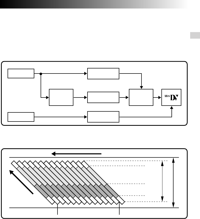
The digital video camera converts incoming audio and video signals into digital form for recording.
A video signal is composed of a luminance signal (Y) and colour signals (R-Y and B-Y). These signals are
identified and recorded digitally (Digital Component Recording). The A/D (Analogue to Digital) converter
samples the Y signal at 13.5 MHz, and R-Y and B-Y at 6.75 MHz, and changes them to an 8-bit quantum signal.
Sound sampled at 48 kHz is changed to a 16-bit quantum signal, and sound sampled at 32 kHz is converted
to a 12-bit signal.
NOTE:
The data recorded on a tape is digital, but the output of the this camcorder is analogue.
ABOUT DV
3Audio Area
The digital audio signal is recorded here.
4ITI (Insert and Tracking
Information) Area
Insert editing and post-recording editing
tracking signals are recorded here.
1Sub-Code Area
The Time Code and Date/Time data are
written here, separate from the video
data. This enables you to display the date
and time during playback, even if they
weren’t displayed while recording.
2Video Area
The digital video signal is recorded here.
Lens
Mic
A/D
conversion
Chromatic
Analysis
12 tracks/frame
VIDEO Luminance Signal (Y)
A/D
conversion
A/D
conversion
AUDIO
Recording by
rotating head
helical scan
Tape direction
Sub-Code Area
Video Area
Audio Area
ITI Area
Head tracking
direction
5.24 mm
6.35 mm
Signal
compression
Colour Difference
Signal (R-Y/B-Y)
Chrominance (C)
This camcorder separates the data into blocks, writing one block of each data type on each track of the tape.
6 EN
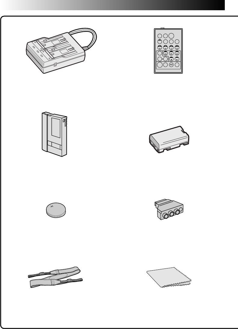
TW
PROVIDED ACCESSORIES
Remote control unit
RM-V711U
AC Power Adapter/Charger
AA-V80EK or AA-V80EA
Battery pack BN-V814U
MiniDV Cassette Tape 30 min
(DVM-30) M-DV30ME
Cable adapter
(Provided only with U.K. models)
Lithium battery CR2025 for remote
control unit (For function confirmation)
Shoulder Strap Cleaning cloth
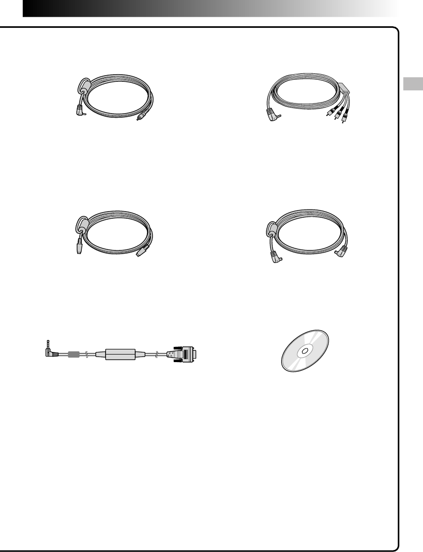
EN 7
S-VIDEO cable DC cord
Editing cable
(ø 3.5 mini-plug, 2 poles)
JLIP-PC connection cable CD-ROM
The CD ROM contains
the following
3 software programmes:
•JLIP Video Capture
•JLIP Video Producer
•MGI PhotoSuite SE
VIDEO/AUDIO cable
(camcorder to TV or VCR,
ø 3.5 mini-plug 4 RCA plug)
8 EN
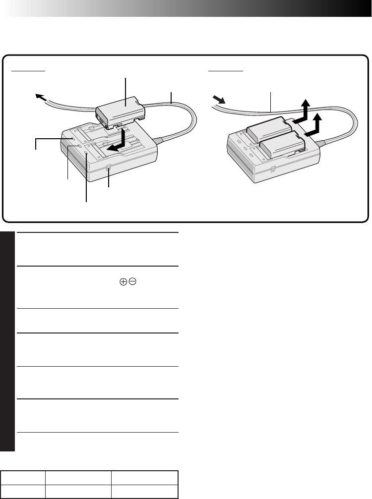
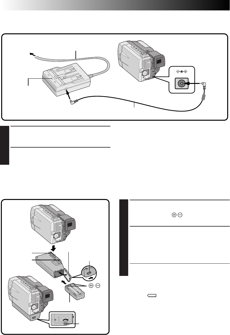
Charging The Battery Pack
You can charge one battery pack at a time, or two consecutively.
GETTING STARTED
ATTACH
NOTES:
●
If you connect the camcorder’s DC cord to the
adapter during battery charging, power is
supplied to the camcorder and charging stops.
●
When using the AC Power Adapter/Charger, be
sure to use the supplied power cord only.
●
The AC Power Adapter/Charger is for use with the
BN-V814U Battery Pack only.
●
When charging the Battery Pack for the first time
or after a long storage period, the Charger
Indicator may not light. In this case, remove the
Battery Pack from the AC Power Adapter/Charger,
then try charging again.
●
Since the AC Power Adapter/Charger processes
electricity internally, it becomes warm during use.
Be sure to use it only in well-ventilated areas.
●
If the battery operation time remains extremely
short even after having been fully charged, the
battery is worn out and needs to be replaced.
Please purchase a new one.
To AC outlet Power cord
Charger indicator 2
Power lamp
Charger
indicator 1
DETACH
1
SUPPLY POWER TO CHARGER
Plug the AC Adapter/Charger’s power cord in
to an AC outlet. The power lamp comes on.
2
ATTACH BATTERY/BATTERIES
Attach while making sure the marks are
facing down and aligned with the correspond-
ing marks on the AC Power Adapter/Charger.
• The Charger Indicator (1 or 2) begins blinking to
indicate charging has started.
3
CONFIRM STATUS
When the charger indicator stops blinking but
stays lit, charging is finished.
• If two batteries are attached to the charger, they
will be charged in the order that they were
attached.
4
DETACH BATTERY/BATTERIES
Slide the battery or batteries in the direction of
the arrow and lift off.
• Remember to unplug the AC Adapter/Charger’s
power cord from an AC outlet.
Battery pack BN-V814U
AC Power
Adapter/Charger
AA-V80EK or
AA-V80EA
BATTERY ONE TWO
BN-V814U Approx. 110 min. Approx. 220 min.
DC OUT jack
Power cord
CHARGING TIME
EN 9
Charging Environment
Perform charging where the temperature is between 10° and 30°C. (20° to 25°C is the ideal temperature range for
charging.) If the environment is too cold, charging may be incomplete.
Continuous Shooting
Continuous shooting is possible (See table below for recording time) under the following conditions:
•A BN-V814U Battery Pack is in use
•The temperature is approximately 20°C
However, . . .
•If the temperature is below 10°C, or
•If zoom or Record-Standby are engaged or LCD monitor is used repeatedly, continuous shooting capability
is reduced significantly. Before extended use, it is recommended that you prepare enough battery packs to
cover 3 times the planned shooting time.
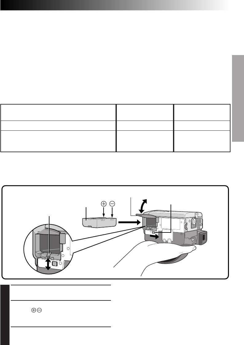
Installing The Battery Pack
The battery pack does not charge while in the camcorder. Before installation, make sure the battery pack has
been charged fully.
1
OPEN BATTERY COVER
Slide the open switch.
2
INSERT CHARGED BATTERY
Insert the mark end of the battery first until
you hear a click. The hook rises. Inserting the
battery backwards will result in malfunction.
3
CLOSE BATTERY COVER
Battery
Battery cover
Hook
Open switch (BATTERY)
NOTES:
●
To remove the battery, turn off the camcorder,
open the battery cover and push down the hook.
●
Be careful not to drop the battery pack.
●
The hook is tight to prevent the battery from
dropping.
No. of batteries to supply power
Using one battery installed in the camcorder
Using two batteries; one in the camcorder and
one in the Power Pack (optional) attached to the
camcorder
Approximate recording time (unit: min)
LCD monitor off/
Viewfinder on
100
180
LCD monitor on/
Viewfinder off
80
140
10 EN
1
INSERT CHARGED BATTERY
Open the battery cover while pressing the
knob and insert the end of the battery
first. Close the battery cover.
2
ATTACH TO CAMCORDER
Align the connector and screw on the Power
Pack while inserting the camcorder connector.
Turn the spring-loaded screw head at the
Power Pack's bottom inward and turn it
clockwise to attach.
•To detach the Power Pack, turn the screw
counterclockwise.
NOTES:
●
When the battery remaining power indicator
appears as , that means the battery power is
close to nil. When the battery power is exhausted,
power turns off automatically.
●
Each time you start shooting, the camcorder
chooses the battery pack that has more remaining
power, and uses that as the power supply. That
means both battery packs will be exhausted at
roughly the same time.
GETTING STARTED
(Cont.)
1
SUPPLY POWER TO ADAPTER
Plug the AC Adapter/Charger’s power cord in
to an AC outlet.
2
SUPPLY POWER TO CAMCORDER
Connect the AC Adapter to the camcorder.
Indoor Use
When using the camcorder indoors, you can use the AC Adapter instead of a battery.
SS
DC-IN
Power lamp
When power is
supplied, the
power lamp lights.
AC Power
Adapter/Charger
Connector is
under the cover
Connector
To AC outlet Power cord
DC cord
Core
Filter
Knob
Battery cover
Screw
Using The Power Pack
For extended use, prepare the optional Power Pack CU-V810, which can be loaded with one battery pack.
This Power Pack can be used together with the battery installed in the camcorder.
NOTE:
When using the provided DC cord, make sure you
connect the end of the cable with the core filter to
the camcorder. The core filter improves perform-
ance of equipment.
Screw head
To DC OUT jack
Battery
Mark
EN 11
A
M
5S
OFF
P
L
A
Y
ON SCREEN OFF
ONDISPLAY
DATE / TIME 1 . 1 . 00
0 : 00
4
RETURN
REC MODE
WIDE MODE OFF
AGC
40X
SP
ZOOM
DIS
GAIN UP
TO DATE / TIME MENU
TO SYSTEM MENU
4
END
ON
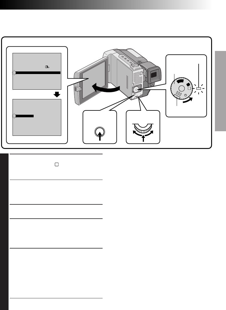
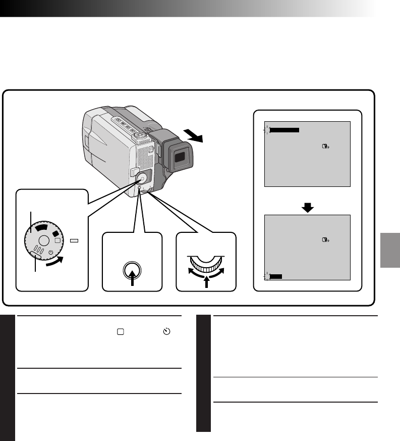
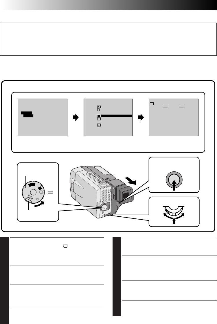
Date/Time Settings
Date and time will automatically be recorded on tape at all times. It is your choice to display it or not during
playback (Z pg. 54).
1
SELECT OPERATION MODE
Set the Power Dial to “
M
” while pressing down
the lock button located on the dial, and open
the LCD monitor fully.
•The power lamp comes on and the camcorder
is turned on.
•The LCD monitor can be tilted upward up to
180 degrees and downward up to 90 degrees.
2
ACCESS RECORDING MENU
Press MENU. The Recording Menu appears.
3
ACCESS DATE/TIME MENU
Move the pointer and highlight bar to “TO
DATE/TIME MENU” by rotating the Select Dial.
Press the Select Dial and the Date/Time Menu
appears.
4
INPUT DATE AND TIME
Move the pointer and highlight bar to “DATE/
TIME” by rotating the Select Dial. Press the
Select Dial and “day” is highlighted and begins
blinking.
Rotating the Select Dial to the right or left, input
the day. Press the Select Dial. Repeat the
procedure to input the month, year, hour and
minute.
•Press the Select Dial twice when the pointer
and highlight bar are set to “RETURN” to exit.
LCD monitor
MENU button
Recording Menu
Date/Time Menu
Lock button
Power Dial
Power lamp
Select Dial
Regarding Built-in Rechargeable Battery
To store the date/time in memory, a rechargeable
clock lithium battery is integrated in the camcorder.
While the camcorder is connected to an AC outlet
using the AC Power Adapter/Charger, or while the
battery pack installed in the camcorder continues to
supply power to the camcorder, the clock lithium
battery is always charged. However, if the
camcorder is not used for approx. 3 months, the
clock lithium battery will become discharged and
the date/time stored in memory will be lost. When
this occurs, first connect the camcorder to an AC
outlet using the AC Power Adapter/Charger etc. for
over 24 hours to charge the clock lithium battery.
Then perform the date/time setting before using the
camcorder.
It is also possible to use the camcorder without the
date/time setting.
NOTE:
If you don’t exit the Date/Time Menu, the clock
display will not move but the camcorder’s internal
clock continues to operate. Once you close the
menu, the date and time begin operation from the
current date and time, with no delay or loss.
12 EN
GETTING STARTED
(Cont.)
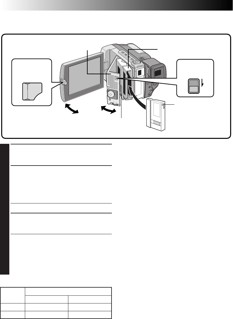
Loading/Unloading A Cassette
The camcorder needs to be powered up to load or eject a cassette.
NOTES:
●
It takes a few seconds for the cassette holder to
open. Do not apply force.
●
If you wait a few seconds and the cassette holder
does not open, close the cassette cover and try
again.
●
Be careful not to get your fingers caught in the
holder when it’s closing. If this happens, the
holder will open automatically after a few
seconds.
●
When the camcorder is suddenly moved from a
cold place to a warm environment, wait a short
time before opening the cover.
●
Closing the cassette cover before the cassette
holder comes out may cause damage to the
camcorder.
●
When shooting again after already shooting a
scene, a blank portion is recorded on the tape or
a previously recorded scene is erased (recorded
over) if you open the cassette cover, regardless of
whether the cassette holder comes out or not. See
page 20 for information about recording from the
middle of a tape.
** To protect valuable recordings . . .
.... slide the erase protection switch on the back of
the tape in the direction of “SAVE”. This prevents
this tape from being recorded over. If you decide
later that you do want to record on this tape, slide
the switch back to “REC” before loading the tape.
PUSH HERE
Cassette cover
Make sure the window
side is facing out.
Cassette holder
Erase protection switch**
PUSH-OPEN
button
1
OPEN LCD MONITOR
Press the PUSH-OPEN button and open the
LCD monitor up to an angle of 90 degrees.
2
OPEN CASSETTE COVER
Turn on the power, then slide the OPEN/EJECT
switch in the direction of the arrow. The
cassette cover releases. Open the cover in the
direction of the arrow until it locks. The holder
opens automatically.
•Do not touch internal components.
3
INSERT/REMOVE TAPE
Insert or remove a tape and press “PUSH
HERE” to close the cassette holder.
•Once the cassette holder is closed, it recedes
automatically. Wait until it recedes
completely before closing the cassette cover.
•When the battery’s charge is low, you may
not be able to close the cover. Do not apply
force. Replace the battery with a fully
charged one before continuing.
TAPE Recording mode
SP LP
DVM-30 Approx. 30 min. Approx. 45 min.
DVM-60 Approx. 60 min. Approx. 90 min.
Recording time
OPEN/EJECT
switch
EN 13
SP SP LP
REC MODE
WIDE MODE OFF
AGC
40X
SP
ZOOM
DIS
GAIN UP
TO DATE / TIME MENU
TO SYSTEM MENU
4
END
ON
REC MODE
WIDE MODE OFF
AGC
40X
SP
ZOOM
DIS
GAIN UP
TO DATE / TIME MENU
TO SYSTEM MENU
4
END
ON
A
M
5S
OFF
P
L
A
Y
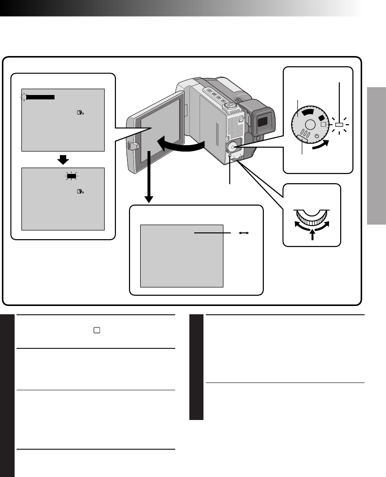
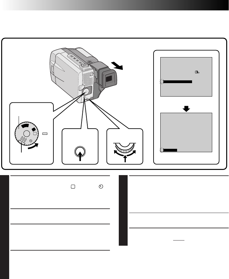
Recording Mode Setting
Set depending on your preference.
1
SELECT OPERATION MODE
Set the Power Dial to “
M
” while pressing down
the lock button located on the dial.
2
OPEN LCD MONITOR
Open the LCD monitor fully.
The power lamp comes on and the camcorder
is turned on.
•The LCD monitor turns on/off automatically
when it is opened/closed at approx. 90 degrees
while the Power Dial is set to any operation
mode (except “OFF”).
•The LCD monitor can be tilted upward up to
180 degrees and downward up to 90 degrees.
3
ACCESS RECORDING MENU
Press MENU. The Recording Menu appears.
4
SET RECORDING MODE
First move the pointer and highlight bar to
“REC MODE” by rotating the Select Dial. Press
the Select Dial and the parameter “SP” or “LP”
is highlighted. Select “SP” or “LP” by rotating
the Select Dial. Press the Select Dial twice to
exit from the Recording Menu.
•Insert Editing or Audio Dubbing is impossible
on a tape recorded in the LP mode.
•“LP” (Long Play) is more economical,
providing 1.5 times the recording time.
NOTES:
●
If the recording mode is switched during
recording, the playback picture will be blurred at
the switching point.
●
It is recommended that tapes recorded in the LP
mode on this camcorder be played back on this
camcorder.
●
During playback of a tape recorded on another
camcorder, blocks of noise may appear or there
may be momentary pauses in the sound.
Recording Menu
Recording mode indicator
LCD monitor
Lock button
Power dial
Power lamp
MENU button Select Dial
14 EN
1
3
2
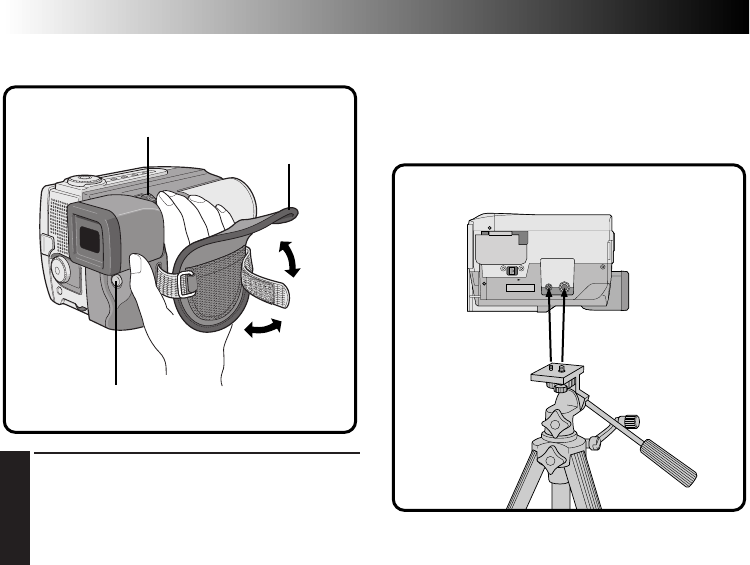
Grip Strap Attachment Tripod Mounting
Align the tripod’s screw with the mounting socket on
the bottom of the camcorder.
The camcorder can be mounted on a tripod even
with the Power Pack attached.
1
ADJUST LENGTH
Open the pad 1. Adjust so that your thumb
and fingers can easily operate the START/STOP
button and the zoom switch. Position the pad
so that it contacts the back of your hand 2,
then re-attach it 3.
START/STOP
Zoom switch
Pad
Bottom of the camcorder
GETTING STARTED
(Cont.)
EN 15
21
1
2
PAUSE
A
M
5S
OFF
P
L
A
Y
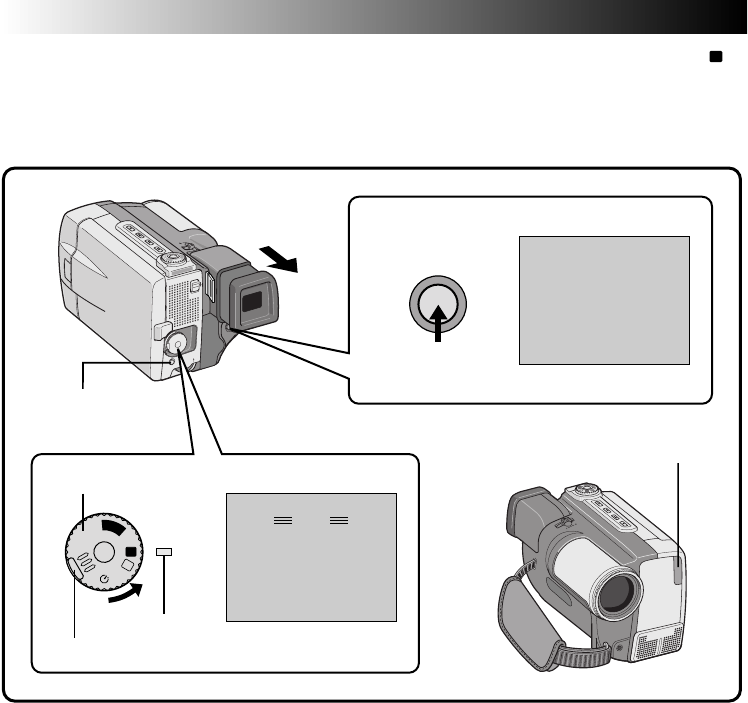
Dioptre Adjustment
Adjust the viewfinder display for best viewing.
1
SELECT OPERATION MODE
Set the Power Dial to “
A
” or “
M
”.
2
TURN ON CAMCORDER
Pull out the viewfinder fully.
3
ADJUST DIOPTRE
Slide the dioptre adjust lever located on the
bottom of the viewfinder.
•Slide in either direction, while looking at the
viewfinder display, until it looks best to you.
Dioptre adjust lever
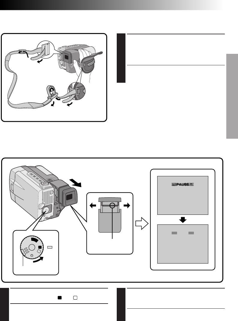
Shoulder Strap Attachment
When transporting the camcorder, it is convenient to use the shoulder strap.
1
ATTACH SHOULDER STRAP
As shown in 1 and 2 of the illustration,
thread the strap through the eyelets and the
buckles. Pull the strap to make sure it is
attached to the camcorder firmly.
•If the strap is not attached correctly and the
camcorder drops, the camcorder may become
damaged.
Lock button
16 EN
GETTING STARTED
(Cont.)
TW
Remote Control Unit
You can use the RM-V711U to control the camcorder. When using the remote control, be sure to point it at
the remote sensor. The transmitted beam effective area for indoor use is approx. 5 m. The transmitted beam
may not be effective or may cause incorrect operation if the remote sensor is directly exposed to sunlight or
powerful lighting.
Installing The Battery
The RM-V711U uses one lithium battery (CR2025).
1
PULL OUT BATTERY HOLDER
Pull out in the direction of the arrow while
pressing the knob as shown.
2
INSERT BATTERY IN HOLDER
Insert the battery in the holder, and be sure to
have the “+” mark visible.
3
RE-INSERT HOLDER
Slide the holder back in until you hear a click.
•Read the caution concerning lithium batteries
(Z pg. 2).
Operation Buttons
(Z pg. 52, 60, 68, 69)
Up Button (Z pg. 52)
INSERT Button (Z pg. 69)
Down Button (Z pg. 52)
AUDIO MONITOR Button
(Z pg. 68)
MBR SET Button (Z pg. 62)
A. DUB Button (Z pg. 68)
START/STOP Button (Z pg. 69)
PAUSE IN connector (Z pg. 63)
EFFECT ON/OFF Button
(Z pg. 53)
EFFECT Button
(Z pg. 53)
FADE/WIPE Button
(Z pg. 64)
Left/Right Buttons
(Z pg. 52)
SLOW Rewind/Forward
Buttons (Z pg. 51)
SHIFT Button (Z pg. 52, 62)
DISPLAY Button (Z pg. 60)
Zoom Buttons (Z pg. 52)
Knob
R.A. EDIT Buttons (Z pg. 65)
EN 17
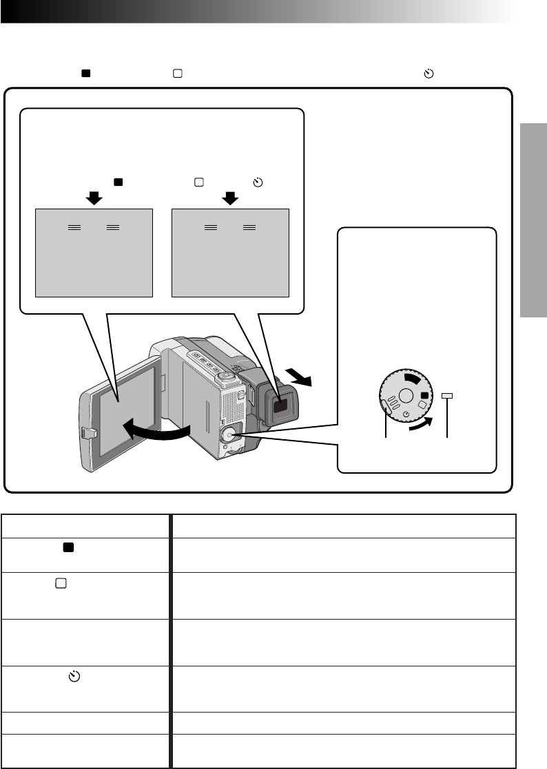
Power Dial Position Function
Allows you to record using NO special effects or manual adjust-
ments. Suitable for standard recording.
Allows you to set various recording functions using the Menus. If you
want more creative capabilities than Full Auto recording, try this
mode.
Allows you to record in 5-second clips to keep the action moving.
Other menu settings are the same as Full Auto mode, however
manually adjusted White Balance Adjustment settings are effective.
Allows you (camcorder operator) to become part of the scene once
the camcorder is set. This mode is similar to the Self-Timer on film
cameras.
Allows you to play back a recording, Z pg. 50 – 59.
Allows you to switch off the camcorder. After setting to this position,
Manual Focus and Exposure Control are automatically reset to "AUTO".
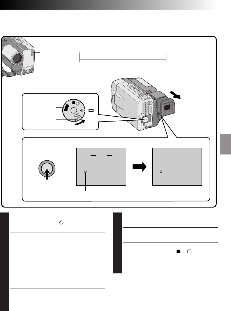
Self-Timer:
Operation Mode
Tuning the Power Dial allows you to choose the appropriate operation mode among the following modes:
Full Auto mode (
A
), Manual mode (
M
), 5 second mode recording (5S), Self-Timer mode ( ) and “PLAY”.
F . AUTO
PAUSE
MANUAL
PAUSE
A
M
5S
OFF
P
L
A
Y
According to the Power Dial position you have
selected, “F.AUTO” or “MANUAL” appears in the
upper left corner.
When set to
“
M
”, “5S” or “ ”When set to “
A
”
Full Auto:
A
Manual:
M
5 second mode recording: 5S
Playback: PLAY
Lock button Power lamp
To turn on the camcorder, first
turn the Power Dial to any
operation mode except “OFF”,
then pull out the viewfinder fully
or open the LCD monitor. When
turning the Power Dial from
“OFF” to any other position,
press and hold the lock button
located on the dial.
OFF
18 EN
You should already have performed the necessary preparations (Z pgs. 8 – 17). Set the Power Dial to “
A
”
and try recording that way before attempting to use more advanced features.
NOTE:
Before starting recording, make sure you set the date and time (
Z
pg. 11). Even if they don’t appear during
recording, you can display them during playback (
Z
pg. 55).
PAUSE
444
REC
PAUSE
A
M
5S
OFF
P
L
A
Y
Lock button
Power Dial
Display
Display
Record-Standby
During recording
Power lamp
START/STOP
button
RECORDING
Basic Recording
ON/OFF
Tally lamp

EN 19
1
SELECT OPERATION MODE
Set the Power Dial to “
A
” while pressing down
the lock button located on the dial.
2
PULL OUT VIEWFINDER OR OPEN
LCD MONITOR
Pull out the viewfinder fully or open the LCD
monitor to approx. 90° degrees.
•The lens cover opens, the power lamp comes
on and the scene you're aimed at appears.
•The Record-Standby mode is engaged.
3
START RECORDING
When “PAUSE” appears, press START/STOP. A
beep signals the start of recording and the tally
lamp comes on.
4
STOP RECORDING
Press START/STOP again to stop recording.
•The camcorder re-enters Record-Standby mode.
5
END RECORDING
When you’re finished recording, push back the
viewfinder or close the LCD monitor until it
clicks; the lens cover closes and the power
lamp goes out.
•When transporting, make sure the viewfinder
is pushed back and the LCD monitor is
closed and locked.
•To turn power on again, pull out the
viewfinder or open the LCD monitor.
OR
Set the Power Dial to “OFF”.
•When turning to “OFF”, it is not necessary to
press down the lock button.
NOTES:
●
The image will not appear simultaneously in the
LCD monitor and the viewfinder. No image
appears on the LCD monitor when the viewfinder
is pulled out. It is not possible to shoot using both
LCD monitor and viewfinder. However, during
Interface Shooting (
Z
pg. 23) the image appears
simultaneously in the LCD monitor and the
viewfinder.
●
If 5 minutes elapse in the Record-Standby mode,
power shuts off automatically to conserve energy
and protect the heads. To turn the camcorder on
again, push back and pull out the viewfinder
again or close and re-open the LCD monitor. As
long as you don’t take out the tape you were
using or play it back, you can continue from
where you left off with no noticeable brake on the
recorded video.
●
When a blank portion is left between recorded
scenes on the tape, the time code is interrupted
and errors may occur when editing the tape.
Continue recording from where you stop so there
are no gaps by following "Recording from the
middle of a tape" (
Z
pg. 20).
●
Record-Standby means that a tape is loaded and
the camcorder is ready to record.
●
During recording, sound is not heard from the
speaker. If you want to hear the sound, connect
optional headphones to the headphones jack. The
sound volume at this point is the same as the level
it was adjusted during playback.
●
To make the indications disappear, press and hold
the ON/OFF button for more than approx. 1
second. However, it is impossible to remove the
tape running indicator “
444
” and warning
indications and so on (
Z
pg. 81).
●
Use the viewfinder when under direct sunlight or
when reflections make it difficult to see the LCD
monitor.
20 EN
A
M
5S
OFF
P
L
A
Y
A
M
5S
OFF
P
L
A
Y
1
SELECT OPERATION MODE
Turn the Power Dial to “PLAY” while pressing
down the lock button located on the dial.
•The power lamp comes on.
2
PULL OUT VIEWFINDER OR OPEN
LCD MONITOR
Pull out the viewfinder fully or open the LCD
monitor to approx. 90° degrees.
3
START SEARCH
Press
4
/6, then press
2
or
3
. Watch in the
viewfinder or the LCD monitor for the spot
where you want to begin recording.
4
ENGAGE STILL MODE
Once you find the spot at which you want to
start recording, press
4
/6 twice to engage the
Still mode.
5
START RECORDING
Turn the Power Dial to any operation mode
except “PLAY” and “OFF”, then press START/
STOP.
•Start recording from a point prior to the end
of the last recording. A few seconds of the
end of the last recording will be erased.
NOTE:
If you start recording from the end of the previous
recording leaving no blank space, there may be
situations where a clean transition is not possible.
Recording From The Middle Of A Tape
When removing a tape on which you were recording, or when you resume recording on a tape after playing
back the recording previously made (without taking the tape out between recordings), perform this proce-
dure.
RECORDING
Basic Recording (Cont.)
Stop button
Play/Pause button
Lock button
Power Dial
START/STOP
button
Rewind button
Power lamp
Fast-forward button
EN 21
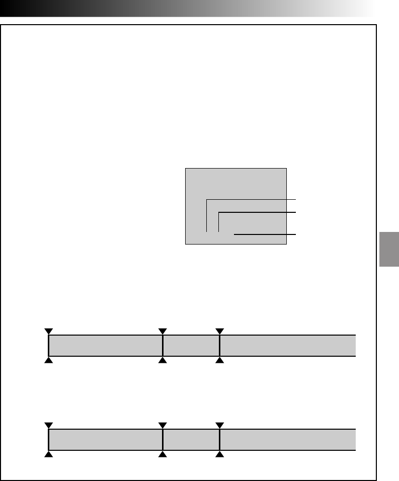
Time Code
During recording, a time code is recorded on the tape. This code is to confirm the location of the
recorded scene on the tape during playback.
If recording starts from a blank portion, the time code begins counting from “00:00:00”
(minute:second:frame). If recording starts from the end of a previously recorded scene, the time code
continues from the last time code number.
To perform Random Assemble Editing (Z pg. 63), time code is necessary. If during recording a blank
portion is recorded partway through the tape, the time code is interrupted. When recording is resumed,
the time code starts counting up again from “00:00:00”. This means the camcorder may record the same
time codes as those existing in a previously recorded scene. To prevent leaving a blank portion on a
tape, perform the procedure in “Recording From The Middle of A Tape” (Z pg. 20) in the following
cases;
•After playing back the recorded tape, when
you shoot again.
•When power shuts off during shooting.
•When a tape is removed and re-inserted
during shooting.
•When shooting using a partially recorded tape.
•When shooting on a blank portion located
partway through the tape.
•When shooting again after already shooting a
scene and opening/closing the cassette cover.
NOTES:
●
The Time Code cannot be reset.
●
During fast-forwarding and rewinding, time code indication does not move smoothly.
Shooting start point
Newly recorded sceneBlankAlready recorded scene
Time code
05:43:21 Time code
00:00:00
Tape
Time code
00:00:00
Shooting start pointShooting stop point
TC 12 : 34 : 24
Display
When blank portion is recorded on a tape
Shooting start point
Time code
05:43:21 Time code
05:44:00
Tape
Time code
00:00:00
Shooting start pointShooting start point
Proper recording
Latest sceneNew sceneAlready recorded scene
Frames
(25 frames = 1 second)
Seconds
Minutes
Time code is displayed
during playback.
22 EN
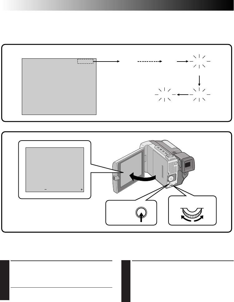
LCD Monitor/Viewfinder Indications
You can make the LCD monitor/Viewfinder
indications appear/disappear.
1
PRESS ON/OFF BUTTON
When you do not want the indications to
appear, press the ON/OFF button for longer
than approximately 1 second. Certain
indications disappear.
Press again for longer than approx. 1 second to
make the indicaitons reappear.
NOTE:
It is impossible to make the tape running indicator
and warnings etc. disappear from the LCD monitor
or the viewfinder. For the indications that can be
removed,
Z
pg. 79.
Brightness Control
You can adjust the brightness of the LCD monitor by
rotating the Select Dial.
1
ADJUST BRIGHTNESS
Rotate the Select Dial to the right or left until
the brightness indicator moves and the LCD
monitor reaches its appropriate brightness.
•The brightness indication appears in the LCD
monitor.
90 min
REC 89 min 3 min 2 min
1 min0 min
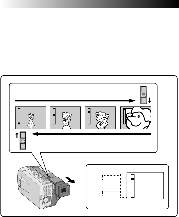
Tape Remaining Indicator
The time remaining on the tape is automatically monitored and displayed (Z pg. 79). When the tape ends,
“TAPE END” appears. If the indications are turned off, the tape remaining indicator appears when remaining
time reaches 2 minutes.
blinking
blinkingblinking
– – – – – – – – – –
6
BRIGHT
RECORDING
Basic Recording (Cont.)
Display
ON/OFF
button
Select Dial
EN 23
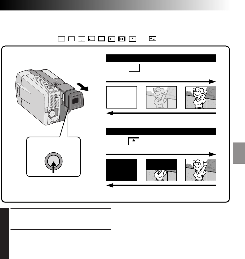
Interface Shooting
The person you are shooting can view himself/
herself in the LCD monitor, and you can even shoot
yourself while viewing your own image in the LCD
monitor.
1
TILT LCD MONITOR UPWARD
Open the LCD monitor and tilt it upward to
180 degrees so that it faces forward.
2
START RECORDING
Point the lens towards the subject (yourself
when self-recording) and start shooting.
•During Interface Shooting, the “Tape Running”
indicator and warning indications (Z pg. 81)
are the only ones that are shown; they appear
reversed in the display as they would when
viewing a mirror, but are not reversed in the
recording.
NOTE:
The tape remaining indicator does not appear
during interface shooting. However, when the
remaining time reaches 2 minutes, the indicator
appears showing the remaining time:
– – –
(blinking)
– –
(blinking)
–
(blinking)
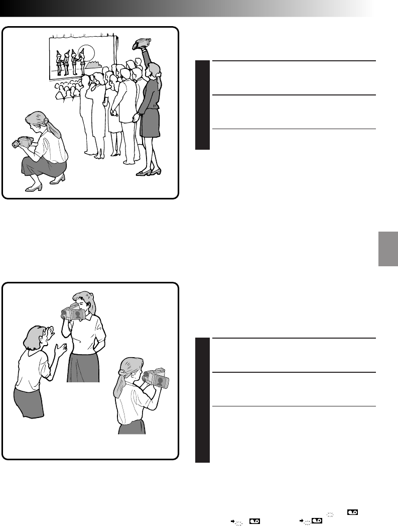
Journalistic shooting
In some situations different angles of shooting may
be required for more dramatic results.
1
OPEN LCD MONITOR
Make sure the viewfinder is pushed back and
the LCD monitor is fully open (approx. 90°).
2
TILT LCD MONITOR
Tilt the LCD monitor in the most convenient
direction.
•The LCD monitor can rotate almost full circle
(270°: 90° downward, 180° upward).
Self-recording
24 EN
T
D
W
T
D
W
T
D
W
T
D
W
T
D
W
W
T
W
T
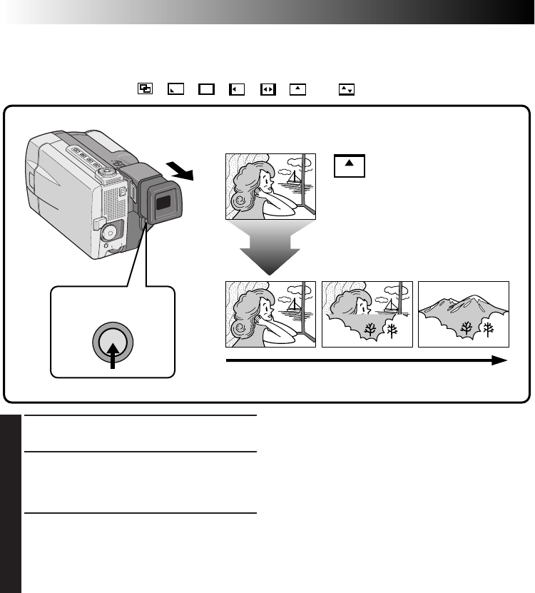
Zoom
Select any one of the three powers of magnification and get “closer” to the subject (Z pg. 33).
Simply set the zoom switch to either zoom in (towards “T”) or zoom out (towards “W”). The zoom speed is
variable — the quicker you set the zoom switch, the quicker the zoom action.
NOTES:
●
Zoom magnification of over 10X is done through Digital image processing, and is therefore called Digital
Zoom.
●
During Digital Zoom, the quality of image may suffer.
●
Digital zoom cannot be used while the Video Echo effect (
Z
pg. 43), the Picture Wipe/Dissolve function
(
Z
pg. 38) or the 5SD mode (
Z
pg. 26) are activated.
●
Macro shooting (as close as approx. 1.5 cm to the subject) is possible when the zoom switch is set all the
way to “W”.
Zoom display
Zoom in (T: Telephoto)
Zoom out (W: Wide angle)
Zoom switch
Digital zoom zone
10X (optical)
zoom zone
RECORDING
Basic Recording (Cont.)
EN 25
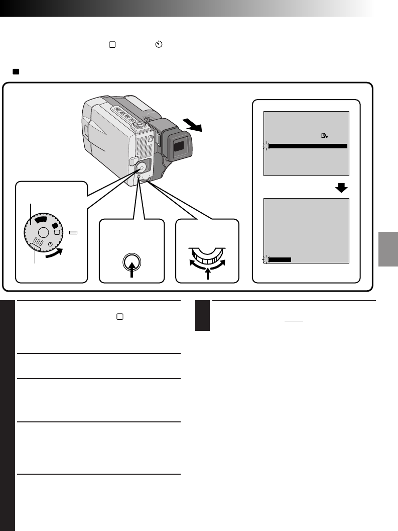
Displaying The Date And Time During Recording
When the Power Dial is set to “
M
”, “5S” or “ ”, you can choose whether to display the date and time
during recording or not. You must first set the date and time (see “Date/Time Settings” Z pg. 11). Set
“DISPLAY” to “ON” in the Date/Time Menu. The Date/Time is always displayed when the Power Dial is set
to “
A
”.
1
SELECT OPERATION MODE
First turn the Power Dial to “
M
” while pressing
down the lock button located on the dial,
make sure the LCD monitor is open fully or the
viewfinder is pulled out.
2
ACCESS RECORDING MENU
Press MENU. The Recording Menu appears.
3
ACCESS DATE/TIME MENU
Move the pointer and highlight bar to “TO
DATE/TIME MENU” by rotating the Select Dial.
Press it and the Date/Time Menu appears.
4
SELECT FUNCTION
Move the pointer and highlight bar to
“DISPLAY” by rotating the Select Dial, then
press it. The pointer stops blinking, indicating
that the function has been selected.
5
SET FUNCTION PARAMETERS
Cycle through the available settings of the
selected functions by rotating the Select Dial
and stop when the one you want is displayed.
Then press it and the pointer and highlight bar
automatically move to “RETURN”.
6
CLOSE RECORDING MENU
Press the Select Dial twice. Selection is
complete and the menu disappears.
NOTES:
●
Connect the camcorder to a TV and set “ON
SCREEN” to “ON” in the Date/Time Menu. The
display appears on the connected TV .
●
The Indicator/Display function overrides these
settings. Even if you have set “ON SCREEN” to
“ON”, pressing the ON/OFF button for longer
than 1 second removes the indications from the
screen. Pressing it for longer than 1 second again
makes the indications re-appear.
REC MODE
WIDE MODE OFF
AGC
40X
SP
ZOOM
DIS
GAIN UP
TO DATE / TIME MENU
TO SYSTEM MENU
4
END
ON
ON SCREEN OFF
ONDISPLAY
DATE / TIME 1 . 1 . 00
0 : 00
RETURN
4
A
M
5S
OFF
P
L
A
Y
Display
Recording Menu
Date/Time Menu
MENU button/
ON/OFF button
Power Dial
Lock button
Select Dial
RECORDING
Advanced Features
26 EN
4
END 5-SECOND MODE RECORDING
Set the Power Dial to the “
A
”, “
M
” or “OFF”
position.
To Take A Snapshot In The 5-Second Mode . . .
.... turn the Progressive Dial to any Snapshot mode
and instead of pressing START/STOP in step 3,
press the Progressive Button. The camcorder
records a 5-second still with the shutter sound
(Z pg. 28). But when the Scene is set to
animation (Z pg. 35) this function is not
available.
NOTE:
When “SCENE” is set to “ANIM.” in the System
Menu, the 5-second recording funcion is not
available. Animation recording of a 1/8-second clip
is taken instead (
Z
pg. 35).
1
SELECT OPERATION MODE
Turn the Power Dial to “5S” while pressing
down the lock button located on the dial.
2
PULL OUT VIEWFINDER OR OPEN
LCD MONITOR
Pull out the viewfinder fully. “5S MODE”
appears.
3
ENGAGE 5S MODE
Then press START/STOP. The tally lamp lights
and beep sounds to indicate the start of
recording, and after 5 seconds the camcorder
enters Record-Standby mode.
•If you press and hold START/STOP within 5
seconds after recording starts, Record-
Standby mode is not engaged.
Scene (5-second recording)
Record a vacation or an important event in 5-second clips to keep the action moving. The 5-Second
function may also be activated during Full Auto operation. But the White Balance remains in the previously
adjusted condition. While the 5-Second mode is activated, Fade/Wipe (Z pg. 36), P.AE/Effects (Z pg. 42)
and other manual operations cannot be performed.
REC
MANUAL
PAUSE
MODE5S
PAUSE
MANUAL
MODE5S
REC
444
A
M
5S
OFF
P
L
A
Y
Dissolves during 5 second mode recording
Before performing the following procedure, make sure that the Digital
Image Stabilizer (DIS) is set to “OFF” (Z pg. 31).
Select “5SD” at the System Menu (Z pg. 34). “5SD
MODE” appears in step 2 below. Record one
5-second clip, and the image at the end of the clip is
stored. If you record the next clip within 5 minutes,
the previous scene dissolves as the new scene appears.
• If you turn the power off, the stored image will be
lost.
Display
Record-Standby
After 5 sec.
Power Dial
Lock button
RECORDING
Advanced Features (Cont.)
START/STOP button
EN 27
MANUAL
PAUSE – – – MANUAL REC
444
A
M
5S
OFF
P
L
A
Y
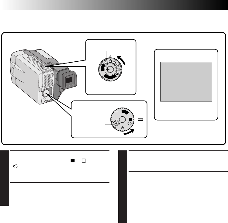
Self-Timer
Once the camcorder is set, the camcorder operator can become part of the scene in a more natural way
adding the final touch to a memorable picture.
1
SELECT OPERATION MODE
Turn the Power Dial to “ ” while pressing
down the lock button located on the dial.
2
PULL OUT VIEWFINDER OR OPEN
LCD MONITOR
Pull out the viewfinder fully.
•The camcorder enters the Record-Standby
mode.
•You can tilt the LCD monitor upward to 180
degrees so that it faces forward and view
yourself while self-recording (with the
viewfinder pushed back).
3
ENGAGE SELF-TIMER MODE
Press START/STOP.
After 15 seconds, the beep sounds and
recording begins.
4
STOP SELF-TIMER RECORDING
Press START/STOP.
•The camcorder re-enters Record-Standby
mode.
5
END SELF-TIMER RECORDING
Set the Power Dial to the “
A
”, “
M
” or “OFF”
position.
•When turning to “OFF”, it is not necessary to
press down the lock button.
To Take A Snapshot In The Self-Timer Mode . . .
.... in step 3, turn the Progressive Dial to any
Snapshot mode, then press the Progressive
Button (Z pg. 28). After approx. 15 seconds, a
snapshot will be taken.
NOTE:
When the Progressive Dial is set to “VIDEO”, the
Self-Timer records using the Progressive Mode.
Power Dial
Display
During recording
Lock button
START/STOP button
Self-Timer indication
After
15 sec.
When the START/
STOP button is
pressed, the tally
lamp changes as
shown at right:
Blinks quickly
(Self-Timer shooting
starts soon)
Stops blinking and
stays on
(Self-Timer shooting
starts)
Begins blinking
(Self-Timer starts)
After approx. 15 sec.
¥¥
4
28 EN
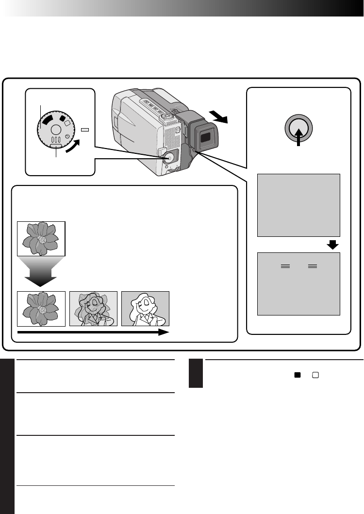
RECORDING
Advanced Features (Cont.)
1
SELECT OPERATION MODE
First turn the Power Dial to “
A
”, “
M
”, “5S” or
“ ” while pressing down the lock button
located on the dial. Make sure the viewfinder
is pulled out or the LCD monitor is open fully.
2
SELECT PRO SNAPSHOT MODE
Choose the appropriate mode among six Pro
Snapshot modes (Z pg. 29) by turning the
Progressive Dial (SNAPSHOT Dial).
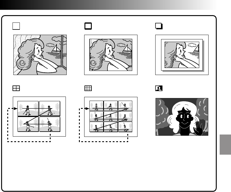
Pro Snapshot
Use your camcorder like a regular camera and take a snapshot, or several of them in succession.
S
N
A
P
S
H
O
T
V
I
D
E
O
PHOTO
A
M
5S
OFF
P
L
A
Y
Power Dial
Lock button
Display
During snapshot
3
TAKE PRO SNAPSHOT
Press the Progressive Button (SNAPSHOT
Button).
If you press during Record-Standby . . .
.... “PHOTO” appears and a still image will be
recorded for approx. 6 seconds, then the
camcorder re-enters the Record-Standby
mode.
If you press during Recording . . .
.... “PHOTO” appears and a still image will be
recorded for approx. 6 seconds, then the
normal recording resumes.
To Perform Pro Snapshot Recording During
Progressive Video Recording (
Z
pg. 44) . . .
.... turn the Progressive Dial to the Pro Snapshot
mode you want, then press the Progressive
Button. To end recording, set the Progressive
Dial to “VIDEO” again, then press the Progres-
sive Button.
Progressive Button
Progressive Dial
EN 29
Motor Drive mode:
Keeping the Progressive Button pressed provides an
effect similar to serial photography. (The interval
between the still pictures: approx. 0.7 seconds.)
To Remove The Shutter Sound . . .
.... When you don't want to hear the shutter sound,
set BEEP/TALLY to “OFF” in the system menu
(Z pg. 35). Though the sound is not heard
from the speaker, it is recorded on the tape.
Progressive Mode:
This mode enables recording a jitter-free still image
with superior quality, using the Progressive Scan
CCD (Z pg. 30).
The Progressive Mode is activated during Pro
Snapshot recordings (except Multi-Analyzer 4 & 9)
and Progressive Video Recording (Z pg. 44).
A recorded high-resolution still image can be
transferred to a personal computer and processed
using the provided software, or can be printed out
using the optional digital printer GV-DT1.
NOTE:
During playback as well, all Pro Snapshot modes
except Nega/Posi mode are available. The shutter
sound is not heard.
Pro Snapshot mode
with no frame* u
Pro Snapshot mode
with frame* uPin-Up mode u
Multi-Analyzer 4** Multi-Analyzer 9** Nega/Posi mode* u
*: There is a momentary camera shutter-type blackout together with the sound effect of a shutter
closing, which is recorded together with the image.
** : This will be disabled when P.AE/Effects other than “SHUTTER” are activated.
u: Recorded with Progressive mode.
30 EN
RECORDING
Advanced Features (Cont.)
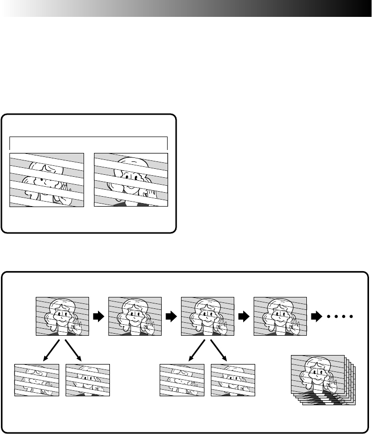
Description of Progressive Scan CCD
Progressive Scan is a special image sensing method which, unlike conventional interlace scanning, is able to
pick up all the lines of picture information in one Scan. Since the Progressive Scan CCD is capable of
outputting 50 full Frames* per second — twice the amount of conventional systems — it is able to deliver a
high quality picture even when its output signal is converted to a format that can be viewed on a TV screen.
* A PAL TV screen image is composed of 25 Frames per second. 1 Frame is made up of 2 Fields.
1. Regular shooting of moving images
1 Frame
Scan BScan A
Odd-number Field Even-number Field
Scan A Scan B
Skip
Scan D
Odd-number
Field Odd-number
Field
Skip
25 Frames per second
Records 25 odd and 25 even image Fields, for a
total of 50 per second. Since there is a time lag
between an odd and even Field, when they are
combined to make 1 Frame the part of the image
that is moving appears as image jitter. However,
during normal playback, the moving picture looks
smooth and natural.
2. Progressive mode shooting of moving images
(Progressive Video Recording Z pg. 44)
Scan C
Scan A is recorded, divided into an odd- and even-number Field, and then Scan B is skipped. Scans C and
D are handled in the same way as Scans A and B, as illustrated above, thereby recording 25 Frames per
second.
Since each recorded odd- and even-number Field originates from the same Scan there is no time lag
between them, and so when they are combined into a Frame and a still image is displayed on a TV or PC
monitor the picture does not look jittery. However, when moving images are played back, the picture can
look unnatural.
3. Pro Snapshot recording (Z pg. 28)
When the Progressive button is pressed, the current frame will be recorded for about 6 seconds in the
Progressive mode (except when a Multiple picture mode is being used).
Even-number
Field Even-number
Field
EN 31
REC MODE
WIDE MODE OFF
AGC
40X
SP
ZOOM
DIS
GAIN UP
TO DATE / TIME MENU
TO SYSTEM MENU
4
END
ON
REC MODE
WIDE MODE OFF
AGC
40X
SP
ZOOM
DIS
GAIN UP
TO DATE / TIME MENU
TO SYSTEM MENU
4
END
ON
A
M
5S
OFF
P
L
A
Y
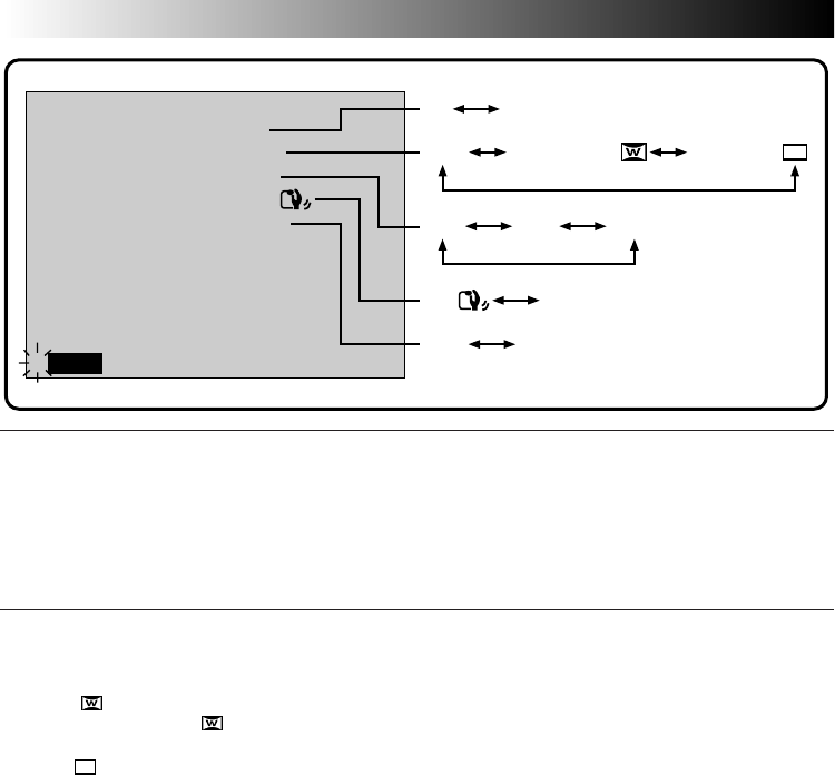
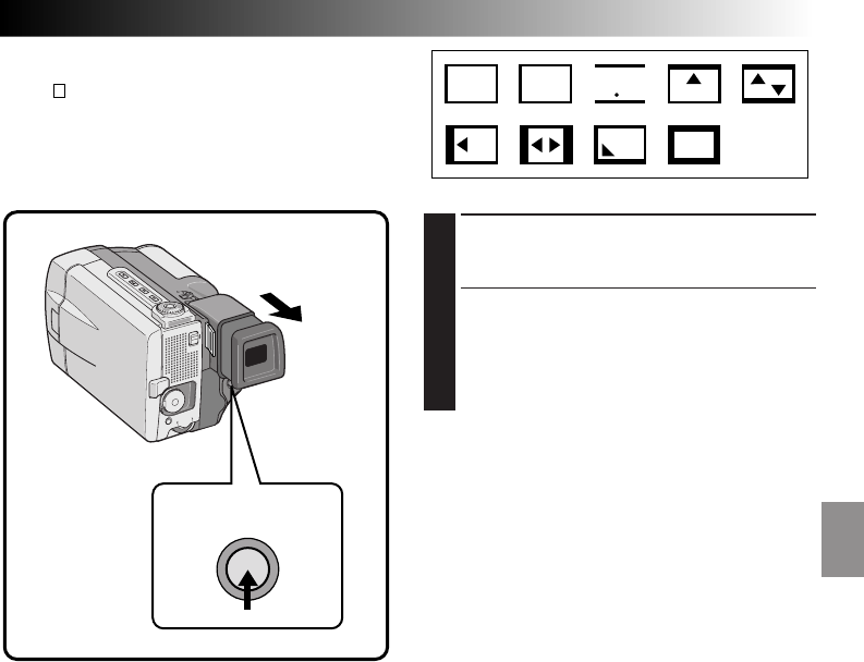
Menus
The Recording Menu allows you to set these functions:
Recording Mode, Wide Mode, Zoom Magnification, Digital Image Stabilizer, Gain Up, Date/Time Menu,
System Menu
. The following selection procedure applies to
Recording Mode, Wide Mode, Zoom Magnifica-
tion, Stabilization and
Gain Up
.
Please refer to pages 32, 33 for details.
1
SELECT OPERATION MODE
First turn the Power Dial to “
M
”, “5S” or “ ”
while pressing down the lock button located
on the dial, make sure the LCD monitor is
open fully or the viewfinder is pulled out.
2
ACCESS RECORDING MENU
Press MENU. The Recording Menu appears.
3
SELECT FUNCTION
Move the pointer and highlight bar to the
desired function by rotating the Select Dial,
then press it. The pointer stops blinking,
indicating that the function has been selected.
Display
Recording Menu
4
SET FUNCTION PARAMETERS
Cycle the available settings of the selected
function by rotating the Select Dial. Stop when
the one you need is displayed. Then press it,
the pointer and highlight bar automatically
move to “END”.
•To set the parameters for a different function,
repeat steps 3 and 4.
5
CLOSE RECORDING MENU
Press the Select Dial. Selection is complete and
the menu disappears.
MENU button
Power Dial
Lock button
Select Dial
32 EN
REC MODE (Recording mode)
You can change the tape recording speed. LP tape speed is slower than SP, allowing LP to record 1.5 times
longer than SP. If you have shot in SP mode Audio Dubbing and Insert Editing will be possible later.
NOTE:
Tapes shot in LP mode are recommended to be played back on this unit. Playback may not be successful on
other units.
WIDE MODE
This recording mode is compatible with wide-screen TVs (16:9 aspect ratio). When using this mode, please
refer to your wide-screen TV’s instruction manual.
SQUEEZE –For playback on TVs with an aspect ratio of 16:9. Naturally expands the image to fit the
screen without distortion. appears. During playback/recording on 4:3 TVs/LCD monitor/viewfinder, the
image is elongated vertically.
CINEMA –Inserts black bands at the top and bottom of the screen. During playback on wide-screen TVs,
the black bands at the top and bottom of the screen are cut and the screen ratio becomes 16:9. During
playback/recording on 4:3 TVs/LCD monitor/viewfinder, black bands are inserted at the top and bottom of
the screen and the image appears like a letterboxed 16:9 movie.
OFF–Select “OFF” when you don’t want to use either of the above modes.
A discriminating signal is automatically recorded when you select either “SQUEEZE” or “CINEMA” for
recording. If your wide TV has the automatic discriminating function, connect an S-Video cable between S2
connector on the TV and the S-Video output connector on the camcorder. During playback, the image is
naturally expanded to fit the wide screen, with no proportional distortion.
If your wide screen TV has no S2 connector, automatic signal discrimination can not be performed, and it
should be done manually.
NOTES:
●
When playing back through a video cassette recorder, or to a wide-screen TV, that does not have the
automatic discriminating function, change the setting on the TV manually.
●
When playing back a tape recorded in Squeeze and Cinema, Squeeze cannot be distinguished from
Cinema during fast-forward or rewind.
●
During Full-Auto operation, both Squeeze and Cinema modes are unusable.
REC MODE
WIDE MODE OFF
ON
AGC
40X
SP
ZOOM
DIS
GAIN UP
TO DATE / TIME MENU
TO SYSTEM MENU
END
4
ON
OFFON
OFF AGC
10X 40X
SP LP
OFF CINEMA
SQUEEZE
100X
RECORDING
Advanced Features (Cont.)

EN 33
ZOOM (Zoom magnification)
You can select 10X, 40X, or 100X maximum zoom magnifications.
10X–Optical zoom that does not degrade the quality of the recording.
40X–Electronic processing (Digital zoom) that lets you get closer up.
100X–Electronically-processed images at 100-times magnification.
NOTES:
●
Even if 40X or 100X is selected, Digital zoom (magnification of over 10X) cannot be used while the Video
Echo effect (
Z
pg. 43), the Picture Wipe/Dissolve function (
Z
pg. 38) or the 5SD mode (
Z
pg. 26) are
activated.
●
During Full-Auto mode, 40X is selected automatically.
DIS (Digital Image Stabilizer)
When recording while holding the camcorder in your hand, or when shooting a subject with little or no
contrast, subtle hand movements will cause shakiness in the recorded image.
ON –Compensates for relatively small shakes that occur when shooting close up. “ ” appears during
recording.
OFF–When shooting with the camcorder in a fixed position or on a tripod, set the Stabilizer to “OFF”.
If you leave it on and then move or turn the camera to follow a moving subject, unnecessary compensation
occurs and this can result in an unnatural recorded image.
NOTES:
●
Even if the stabilizer is set to “OFF” in Manual mode, it is automatically set to “ON” in Full Auto Mode.
●
The Stabilizer cannot compensate for drastic hand movements while shooting.
●
The Stabilizer will not work if the scene has little or no contrast.
●
The “ ” indicator appears blinking if the Stabilizer cannot be used.
GAIN UP
Bright, natural recordings can be taken even in areas with low or poor lighting.
AGC–This is the factory setting, and is automatically activated during Auto operation. The overall appear-
ance is jagged, but the image is bright.
OFF–Select this setting when lighting is not a problem. Enables recording of the actual brightness you see.
34 EN
ON
OFF
32kHz
06
5SSCENE
BEEP / TALLY
WIND CUT
SOUND MODE
ID NUMBER
RETURN
4
REC MODE
WIDE MODE OFF
ON
AGC
40X
SP
ZOOM
DIS
GAIN UP
TO DATE / TIME MENU
TO SYSTEM MENU
4
END
A
M
5S
OFF
P
L
A
Y
1
SELECT OPERATION MODE
First turn the Power Dial to “
M
”, “5S” or “ ”
while pressing down the lock button located
on the dial, make sure the LCD monitor is
open fully or the viewfinder is pulled out.
2
ACCESS RECORDING MENU
Press MENU. The Recording Menu appears.
3
ACCESS SYSTEM MENU
Move the pointer and highlight bar to “TO
SYSTEM MENU” by rotating the Select Dial,
then press it. The System Menu appears.
4
SELECT FUNCTION
Place the pointer and highlight bar to the
desired function by rotating the Select Dial,
then press it. The pointer stops blinking,
indicating that the function has been selected.
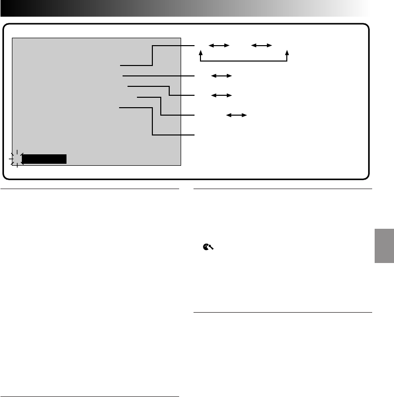
System Menu
The System Menu allows you to set the following functions:
Scene, Beep/Tally, Wind Cut, Sound Mode and
ID numbers.
System Menu
5
SET FUNCTION PARAMETERS
Rotate the Select Dial to cycle through the
available settings for the selected function, and
stop when the desired setting appears. Then
press it, and the pointer and highlight bar
automatically move to “RETURN”.
•To set the parameters for a different function,
repeat steps 4 and 5.
6
CLOSE SYSTEM MENU
Press the Select Dial twice. Setting is complete
and the System Menu disappears.
Display
Recording Menu
Power Dial
RECORDING
Advanced Features (Cont.)
MENU button
Lock button
Select Dial
EN 35
ON
OFF
32kHz
06
5SSCENE
BEEP / TALLY
WIND CUT
SOUND MODE
ID NUMBER
RETURN
4
32kHz 48kHz
5S ANIM.
ON OFF
ON OFF
5SD
SCENE (5-Second Mode) (Z pg. 26)
5S–Pressing START/STOP allows you to take a 5-
second “clip”. Press repeatedly for a succession of
short recordings.
5SD–If you record a 5-second clip within 5 minutes
after the previous one, the end of the old scene
dissolves and is replaced by the new scene over a
2-second period.
ANIM. (Animation)–Each time you press START/
STOP, a 1/8-second recording is taken. By using an
inanimate object and changing its position between
shots, you can record the subject as though it’s
moving.
•
Animation is not available in the LP mode. If you
tried to record in the LP mode after setting ANIM.,
the recording mode indicator "LP" begins to blink,
and recording goes on in the SP mode.
NOTE:
During use of SCENE effect, focus (
Z
pg. 45) and
exposure control (
Z
pg. 46) enter Full Auto
operation.
BEEP/TALLY
The beep sounds when the power is turned on or
off, and at the beginning and end of recording.
Tally lamp lights up during recording.
The following three Pro Snapshot modes (Z pg. 28)
have a shutter sound effect: Pro Snapshot mode
with no frame, Pro Snapshot mode with frame and
Nega/Posi mode.
ON–To activate the beep/shutter sounds and tally
lamp.
OFF–To turn off the beep/shutter sounds and tally
lamp. Even though not heard while shooting,
shutter sound is recorded on the tape.
NOTE:
Beep/Tally is automatically turned on during Full
Auto operation.
This number is necessary when connecting
the camcorder to a computer [01 to 99].
WIND CUT
When activated, this mode helps cut down on noise
created by wind.
ON–When shooting in high winds, noise is
automatically reduced.
•“ ” appears.
•The quality of the sound will change. This is normal.
OFF–This function is disabled.
NOTE:
The Wind Cut mode is disabled during Full Auto
operation.
SOUND MODE
Sound signals can be sampled at 32 kHz or 48 kHz.
32 kHz–The camcorder is factory-preset for 32 kHz.
This setting enables recording of stereo sound on
four separate channels, and is recommended for use
when performing Audio Dubbing.
48 kHz–This setting enables recording of stereo
sound on two separate channels.
NOTE:
A tape recorded at 48 kHz cannot be used for Audio
Dubbing.
36 EN
MANUAL
PAUSE
WH
FOCUS
EXPOSURE AUTO
OFF
OFF
AUTO
AUTO
W. BALANCE
FADER
/ WIPE
P. AE
/ EFFECT
RETURN
4
FADER / WIPE
FADER–BLACK
FADER–B.W
WIPE–SHUTTER
RANDOM
OFF
FADER–WHITE
P
R
?
W
H
B
K
B W
WIPE–CORNER
SEL.
4
A
M
5S
OFF
P
L
A
Y
RECORDING
Advanced Features (Cont.)
FADE/WIPE Effects
1
SELECT OPERATION MODE
First turn the Power Dial to “
M
” while pressing
down the lock button located on the dial, make
sure the LCD monitor is open fully or the
viewfinder is pulled out.
2
ACCESS MANUAL MODE ITEM
MENU
Press the Select Dial.
3
ACCESS FADER/WIPE MENU
Move the pointer and highlight bar to “FADER/
WIPE” by rotating the Select Dial and then press
it. The Fader/Wipe Menu appears.
4
SELECT EFFECT
Move the pointer and highlight bar to the desired
effect by rotating the Select Dial, then press it.
•The Fader/Wipe Menu disappears and the effect
is reserved. The indicator representing the
selected effect appears.
5
START RECORDING
Press START/STOP to start recording and activate
fade- or wipe- in
OR . . .
END RECORDING
Press START/STOP to end recording and activate
fade- or wipe- out.
6
TO CANCEL FADE/WIPE EFFECTS
In step 4, move the pointer and highlight bar to
“OFF”. Press the Select Dial.
Lock button
Power Dial
Display
Fader/Wipe MenuManual Mode Item Menu
START/STOP button
Select Dial
IMPORTANT:
●
When the Digital Image Stabilizer is activated, the Fade/Wipe Effects are not available.
●
If certain P.AE/Effects (
Z
pg. 42) are activated or if the Progressive Dial is set to "VIDEO", some Fade/
Wipe Effects cannot be used. If you select a Fade/Wipe Effect that is unusable in the current situation,
the indication blinks.
Use these to spice up the transition from one scene to the next. You can also vary transitions from scene to
scene. Refer to pages 36 – 41 for Fade/Wipe effects and techniques.
Select any one effect from the Fader/Wipe Menu.
EN 37
Fades and Wipes
A scene gradually appears on a black or white screen (Fade In/Wipe In), or disappears, leaving a black or
white screen (Fade Out/Wipe Out). Select Fade or Wipe at the Fader/Wipe Menu (Z pg. 36).
Select any one effect from
W
H
,
B
K
,
B W
, , , , , , and of the Fader/Wipe Menu.
1
ACTIVATE FADE IN OR WIPE IN
Press START/STOP to start recording, and the
Fade In or Wipe In occurs automatically.
2
ACTIVATE FADE OUT OR WIPE OUT
When you want to stop recording the scene,
press START/STOP. Before the camcorder
enters the Record-Standby mode, the Fade Out
or Wipe Out occurs automatically.
FADE
WIPE
Example
W
H
FADER – WHITE
Example WIPE – SCROLL
Fade Out
Wipe In
NOTE:
You can extend the length of a fade or wipe by
pressing and holding the START/STOP button.
Fade In
Wipe Out
START/STOP button
38 EN
RECORDING
Advanced Features (Cont.)
P
Picture Wipe/Dissolve
Combine the Picture Wipe and Dissolve functions for a professional transition effect. There are 6 Picture
Wipe effects and 1 Dissolve effect. Select the Picture Wipe effect at the Fader/Wipe Menu (Z pg. 36).
Select any one effect from
P
,
P
,
P
,
P
,
P
,
P
and
P
of the Fader/Wipe Menu.
1
START RECORDING
Press START/STOP.
2
ENGAGE RECORD-STANDBY MODE
Press START/STOP when one scene is finished.
The point at which the scene ended is stored in
memory.
3
RESUME RECORDING
If you start recording a new scene within 5
minutes of the end of the previous recording
(without having turned the camcorder’s power
off), the previous scene wipes out, revealing
the new scene.
The next scene gradually wipes in over the
previous scene.
NOTES:
●
If you turn off the power after having finished
recording a scene, the stored point is erased.
This disables the Picture Wipe/Dissolve
combination. When this happens, the Picture
Wipe/Dissolve indicator blinks. Try recording
again, but don’t turn the power off when you’re
finished. Please be advised that power also shuts
off automatically if 5 minutes elapse in the
Record-Standby mode. The camcorder stores the
end point of the last recorded scene, and you can
use Picture Wipe/Dissolve between the last scene
and the next one.
●
The sound at the end of the last recorded scene is
not stored.
Wipe In
Within 5 minutes . . .
WIPE – SCROLL
Example
Previous scene end
START/STOP button
EN 39
Random Variations
When
R
?
is selected, the camcorder chooses one of
the fades/wipes at random.
1
START RECORDING
Press START/STOP. The camcorder does the
rest, selecting an effect at random.
•The recording starts with a Fade In or Wipe
In. If you press START/STOP during record-
ing, Record-Standby mode is preceded by a
Fade Out or Wipe Out; when you resume
recording, it begins with a Fade In or Wipe
In.
NOTE:
The Picture Wipe/Dissolve feature is not available
when Random Fader is activated.
W
H
B
K
B W
START/STOP button

40 EN
MENU EFFECT
Fade in or out with a white screen.
Fade in or out with a black screen.
Fade in to a colour screen from a black and white screen, or
fade out from colour to black and white.
Wipe in on a black screen from the upper right to the lower left
corner, or wipe out from lower left to upper right, leaving a black
screen.
The scene starts in the centre of a black screen and wipes in
toward the corners, or comes in from the corners, gradually
wiping out to the centre.
Wipe in from right to left, or wipe out from left to right.
Wipe in as the two halves of a black screen open to the left and
right, revealing the scene, or wipe out and the black screen
reappears from left and right to cover the scene.
The scene wipes in from the bottom to the top of a black screen,
or wipes out from top to bottom, leaving a black screen.
Wipe in toward the centre of a black screen from the top and
bottom, or wipe out from the centre toward the top and bottom,
leaving a black screen.
RECORDING
Advanced Features (Cont.)
FADER AND WIPE MENU
W
H
FADER — WHITE
B
K
FADER — BLACK
B W
FADER — B.W
WIPE — CORNER
WIPE — WINDOW
WIPE — SLIDE
WIPE — DOOR
WIPE — SCROLL
WIPE — SHUTTER
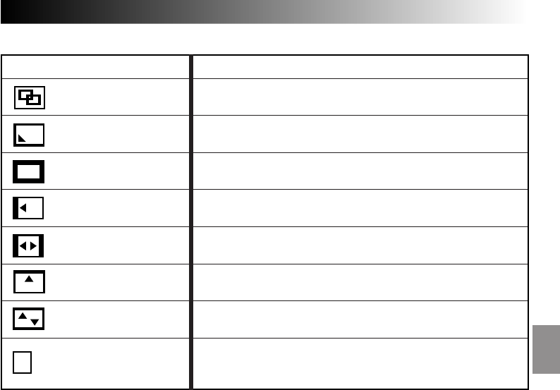
EN 41
MENU EFFECT
The new scene gradually appears as the old one gradually
disappears.
The new scene wipes in over the previous one from the upper
right corner to the lower left corner.
The next scene gradually wipes in from the centre of the screen
toward the corners, covering the previous scene.
The next scene gradually wipes in over the previous one from
right to left.
The previous scene wipes out from the centre to the right and
left, like a door being pushed open to reveal the next scene.
The new scene wipes in over the last one from the bottom of the
screen to the top.
The new scene wipes in over the previous one from the center
toward the top and bottom of the screen.
When this function is activated, the camcorder randomly selects
the effect used in scene transition (from the Fade and Wipe
effects).
P
DISSOLVE
P
WIPE — CORNER
P
WIPE — WINDOW
P
WIPE — SLIDE
R
?RANDOM
P
WIPE — SHUTTER
P
WIPE — DOOR
P
WIPE — SCROLL
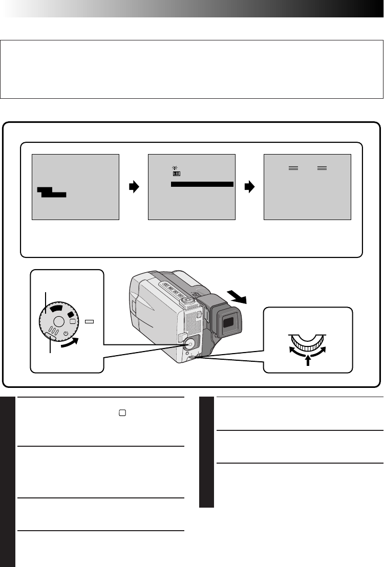
42 EN
RECORDING
Advanced Features (Cont.)
•The P.AE/Effect Menu disappears and the
selected mode is activated. The symbol of the
selected mode appears.
5
START RECORDING
Press START/STOP. The image begins with the
selected effect.
6
DISABLE P.AE/EFFECT
To turn off the selected effect, re-access the
P.AE/Effect Menu and move the pointer and
highlighlt bar to “OFF” by rotating the Select
Dial. Then press it.
NOTE:
P.AE/Effects can be changed during recording or
during Record-Standby.
P.AE/Effects
FOCUS
EXPOSURE AUTO
OFF
OFF
AUTO
AUTO
W. BALANCE
FADER
/ WIPE
P. AE
/ EFFECT
RETURN
4
P. AE / EFFECT
SHUTTER
SHUTTER
SLOW SHUTTER
VIDEO ECHO
OFF
SHUTTER
1/250
1/50
1/100 1/250
1/50
1/100
SHUTTER
1/500 1/500
SEL.
4
A
M
5S
OFF
P
L
A
Y
PAUSE
1/50
Display
Manual Mode Item Menu The indicator for the selected
mode appears, and the selected
mode is engaged.
P.AE/EFFECT Menu
1
SELECT OPERATION MODE
First turn the Power Dial to “
M
” while pressing
down the lock button located on the dial,
make sure the LCD monitor is open fully or the
viewfinder is pulled out.
2
ACCESS MANUAL MODE ITEM
MENU
Press the Select Dial and move the pointer and
highlight bar to "P.AE/EFFECT" by rotating the
Select Dial.
3
ACCESS P.AE/EFFECT SELECT MENU
Press the Select Dial. The P.AE/Effect Menu
appears.
4
SELECT EFFECT
Move the pointer and highlight bar to the
desired effect by rotating the Select Dial, then
press it.
Lock button
Power Dial
Select Dial
IMPORTANT:
●
When the Digital Image Stabilizer is activated, the P. AE/Effects other than "SHUTTER" are not available.
●
If certain Fades or Wipes (
Z
pg. 36 – 41) are activated or if the Progressive Dial is set to "VIDEO", some
P.AE/Effects cannot be used. If you select a P.AE/Effect that is unusable in the current situation, the
effect’s symbol begins flashing.
You can choose any one of the effects from the P.AE/Effect Menu.
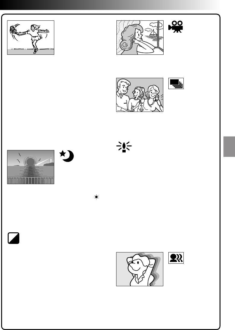
EN 43
B
/
W
SHUTTER
(Variable Shutter
(Speed)
1/50–The shutter speed is fixed at 1/50th of a
second. Black bands that usually appear when
shooting a TV screen become narrower.
1/100–The shutter speed is fixed at 1/100th of a
second. The flickering that occurs when shooting
under a fluorescent light or mercury-vapour lamp
is reduced.
1/250, 1/500–These settings allow fast-moving
images to be captured one frame at a time, for
vivid, stable slow-motion playback. The faster the
shutter speed, the darker the picture becomes.
Use the shutter function under good lighting
conditions.
TWILIGHT
Makes evening scenes look more natural.
White Balance (Z pg. 48) is initially set to ,
but can be changed to your desired setting. Also
when Twilight is chosen, the manual focus
indication appears.
Like classic black and white films, your footage is
shot in B/W. Used together with the Cinema
mode, it enhances the “classic film” effect.
Recorded scenes have a brownish tint like old
photos. Combine this with the Cinema mode for
a classic look.
CLASSIC FILM
STROBE
Your recording looks like a series of consecutive
snapshots.
The Shutter Speed is set to 1/25 sec. to double
the sensitivity.
You can light dark subjects or areas even brighter
than they would be under good natural lighting.
SEPIA
MONOTONE
NOTES:
●
When using Slow Shutter, the image takes on a
strobe-like effect.
●
Use Slow Shutter only in dark areas.
●
The Manual Focus indication may appear and
flash when Slow Shutter is in use.
●
If the image is out of focus, adjust manually. It
is also recommended that you use a tripod, if
possible.
Adds a “ghost” to the subject, giving your
recording a “fantasy” feeling.
VIDEO ECHO
Gives recorded scenes a strobe effect.
SLOW SHUTTER
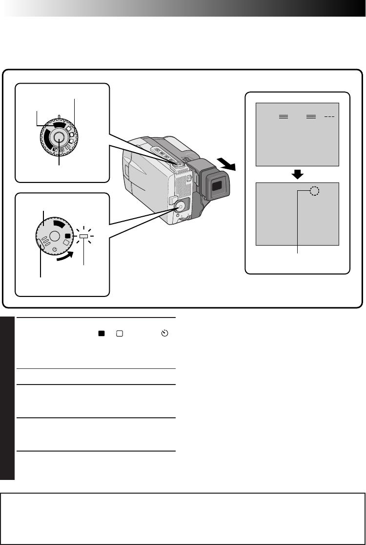
44 EN
RECORDING
Advanced Features (Cont.)
PAUSE
35 min
25 . 12 . 98
17 : 46
444
RECPS
F. AUTO
F. AUTO
S
N
A
P
S
H
O
T
V
I
D
E
O
A
M
5S
OFF
P
L
A
Y
Progressive Video Recording
If an image is recorded using the Progressive Mode, it is possible to play back a jitter-free still image with
superior quality. A high-resolution still image can also be processed on a personal computer or can be
printed out (Z pg. 58, 59).
Display
To Perform Pro Snapshot Recording during
Progressive Video Recording . . .
.... First turn the Progressive Dial to the Pro
Snapshot Mode you want, then press the
Progressive Button. To end recording, turn the
Progressive Dial to “VIDEO”, then press the
Progressive Button again.
NOTES:
●
To perform Progressive Video Recording, the
Progressive Button should be pressed during
Record-Standby; it cannot be activated during
recording.
●
If START/STOP is pressed instead of the Progres-
sive Button, the camcorder starts recording using
the operation mode to which the Power Dial is set
at that moment (
Z
pg. 17). “PS” disappears.
1
SELECT OPERATION MODE
Turn the Power Dial to “
A
”, “
M
”, “5S” or “ ”
while pressing down the lock button located
on the dial. Make sure the LCD monitor is
open fully or the viewfinder is pulled out.
•The power lamp comes on.
2
SELECT PROGRESSIVE MODE
Turn the Progressive Dial to “VIDEO”.
“PS” (Progressive Mode Display) comes on.
3
START RECORDING
Press the Progressive Button located on the
Progressive Dial. The tally lamp comes on.
4
END RECORDING
Press the Progressive Button. The camcorder
enters Record-Standby mode.
VIDEO mode
Progressive Dial
Progressive Button
Lock button
Power Dial
Power lamp
Progressive mode display
IMPORTANT:
●
When an image recorded using the Progressive Mode is played back, the image may not look natural.
●
When the Progressive Dial is set to “VIDEO”, Wipe/Dissolve (
Z
pg. 41) Effects and some P.AE/Effects
(
Z
pg. 43) cannot be used.
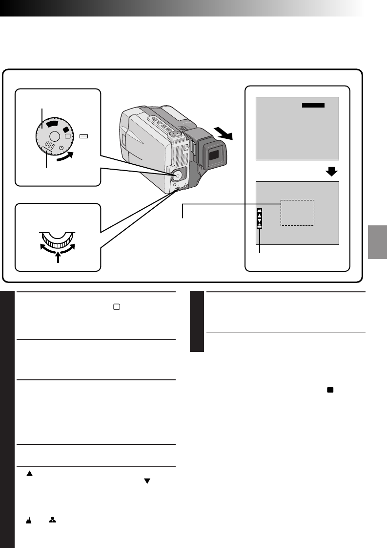
EN 45
FOCUS
FOCUS
EXPOSURE AUTO
OFF
OFF
AUTO
MANUAL
W. BALANCE
FADER
/ WIPE
P. AE
/ EFFECT
RETURN
4
A
M
5S
OFF
P
L
A
Y
Manual Focus Adjustment
The camcorder, in most cases, adjusts the focus from approx. 1.5 cm to infinity automatically. However,
when focusing is difficult or when the subject is not in the middle of the LCD monitor or the viewfinder,
adjust the focus manually. Factory preset is “AUTO”.
Display
5
END ADJUSTMENT OF FOCUS
Press the Select Dial. Focus adjustment is
complete. The indication changes from
“FOCUS” to “MANUAL”.
•If you want to reset the focus, repeat from
step 2.
To Change To Auto Focus . . .
.... Rotate the Select Dial to display “AUTO” then
press it in step 3. The manual focus indicators
disappear. Or set the Power Dial to “
A
”.
NOTES:
●
When “FOCUS” is not displayed, Manual Focus
Adjustment is not available. To make it appear,
press ON/OFF for longer than 1 second or repeat
from step 2.
●
Manual focus is recommended in the following
situations:
•
When shooting a flat wall, a blue sky or an
object with little or no contrast.
•
When wire or other obstacles come between the
camcorder and the subject.
•
When shooting objects with a detailed design or
pattern.
•
When shooting under flourescent or flickering
lighting.
1
SELECT OPERATION MODE
First turn the Power Dial to “
M
” while pressing
down the lock button located on the dial,
make sure the LCD monitor is open fully or the
viewfinder is pulled out.
2
ACCESS MANUAL MODE ITEM
MENU
Press the Select Dial. The Manual Mode Item
Menu appears.
3
ACCESS MANUAL FOCUS
Move the pointer and highlight bar to “FOCUS”
by rotating the Select Dial, then press it. Rotate
the Select Dial to display “MANUAL”, then
press it. The Manual Mode Item Menu disap-
pears and “FOCUS” is displayed in the upper
left corner. The focus is locked at this point.
4
ADJUST FOCUS
Rotate the Select Dial.
•“ ” blinks while rotating the Select Dial to the
right to focus on faraway targets, and “ ”
blinks while rotating the Select Dial to the left to
focus on closer targets. Press the Select Dial at
your desired focus.
•When the focus reaches its near or far limit, the
“” or “ ” will begin blinking.
•When focus cannot be adjusted manually, try
zooming in or out, then try the manual focus
adjustment again.
Manual Mode Item
Menu
Manual focus indicator
Focus zone
(Focus is adjusted at the
centre of the screen)
Lock button
Power Dial
Select Dial
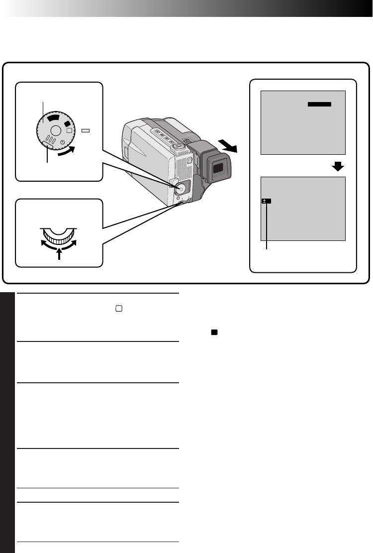
46 EN
1
SELECT OPERATION MODE
First turn the Power Dial to “
M
” while pressing
down the lock button located on the dial,
make sure the LCD monitor is open fully or the
viewfinder is pulled out.
2
ACCESS MANUAL MODE ITEM
MENU
Press the Select Dial. The Manual Mode Item
Menu appears.
3
ACCESS EXPOSURE CONTROL
Move the pointer and highlight bar to “EXPO-
SURE” by rotating the Select Dial, then press it.
Rotate the Select Dial to display “MANUAL”,
then press it. The Manual Mode Item Menu
disappears and “EXP.” and the Exposure
Control indicator are displayed.
4
ADJUST EXPOSURE
Rotate the Select Dial to the right/left to
brighten or darken the image. Press the Select
Dial at your desired exposure.
• The adjustment range is from –6 to +6.
5
END ADJUSTRMENT OF EXPOSURE
Press the Select Dial. Exposure adjustment is
complete. The indication “EXP.” changes to
“MANUAL”.
• If you want to reset the exposure, repeat step 2.
Exposure Control
Usually this is adjusted automatically. However, when the background is too bright or too dark in compari-
son with the subject, the exposure could be corrected manually. Factory preset is “AUTO”.
FOCUS
EXPOSURE MANUAL
OFF
OFF
AUTO
AUTO
W. BALANCE
FADER
/ WIPE
P. AE
/ EFFECT
RETURN
4
EXP.
0
A
M
5S
OFF
P
L
A
Y
Manual Mode Item
Menu
Display
Exposure control indicator
Lock button
Power Dial
Select Dial
To Return To Automatic Exposure Control . . .
.... Rotate the Select Dial to display “AUTO” then
press it in step 3. The Exposure Control
indicator disappears. Or set the Power Dial to
“
A
”.
NOTES:
●
When “EXP.” is not displayed, Manual Exposure
Control is not available. To make it appear, press
ON/OFF for longer than 1 second or repeat from
step 2.
●
Manual exposure adjustment is recommended in
the following situations:
•
When shooting using reverse lighting or when
the background is too bright.
•
When shooting on a reflective natural back-
ground such as at the beach or when skiing.
•
When the background is overly dark or the
subject light.
Brightness control of the LCD monitor
To adjust the brightness of the LCD monitor, rotate
the Select Dial (Z pg. 22). Note that the actual
recorded image's brightness can not be changed by
rotating this dial.
RECORDING
Advanced Features (Cont.)
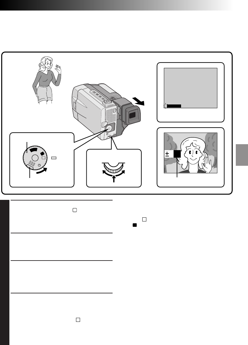
EN 47
1
SELECT OPERATION MODE
First turn the Power Dial to “
M
” while pressing
down the lock button located on the dial,
make sure the LCD monitor is open fully or the
viewfinder is pulled out.
2
ACCESS MANUAL MODE ITEM
MENU
Press the Select Dial. The Manual Mode Item
Menu appears.
3
ACCESS EXPOSURE CONTROL
Move the pointer and highlight bar to “EXPO-
SURE” by rotating the Select Dial and then
press it. Rotate the Select Dial to display
“MANUAL”, then press it. “EXP.” is displayed.
4
CENTER SUBJECT, LOCK IRIS
Adjust zoom so that the subject fills the LCD
monitor or the viewfinder, then press and hold
the Select Dial for over 2 seconds. The
exposure setting display and “ L” appear,
indicating that the iris is locked.
Press the Select Dial. The indication displayed
in the upper left corner changes from “EXP.” to
“MANUAL”.
Iris Lock
Use this function when shooting a moving subject, when zooming, when the subject changes its distance
(thus its size in the LCD monitor or the viewfinder), or when you want to lock the brightness level.
When the subject is close, keep the iris locked. Even when the subject moves away from you, the image will
not darken.
To Return To Automatic Iris Control . . .
.... Rotate the Select Dial to display “AUTO” then
press it in step 3. The Exposure Control indicator
and “ L” disappear. Or set the Power Dial to
“
A
”.
NOTES:
Iris lock is recommended in the following situa-
tions:
●
When shooting on a reflective natural background
such as at the beach or when skiing.
●
When shooting objects under a spotlight.
●
When the subject is backing away.
●
When zooming.
To lock the exposure control and the iris . . .
.... After step 3, adjust the exposure rotating the
Select Dial. Then lock the iris in step 4. For
automatic locking, rotate the Select Dial to
display "AUTO", then press it in step 3. The iris
becomes automatic after about 2 seconds.
Iris
Works like the pupil of the human eye. In a well-lit
environment, the human pupil contracts to keep too
much light from enterintg. In low lighting, the pupil
dilates to allow more light in.
FOCUS
EXPOSURE MANUAL
OFF
OFF
AUTO
AUTO
W. BALANCE
FADER
/ WIPE
P. AE
/ EFFECT
RETURN
4
0 L
A
M
5S
OFF
P
L
A
Y
Power Dial
Lock button
Display
Manual Mode Item Menu
Iris lock indicator
Select Dial
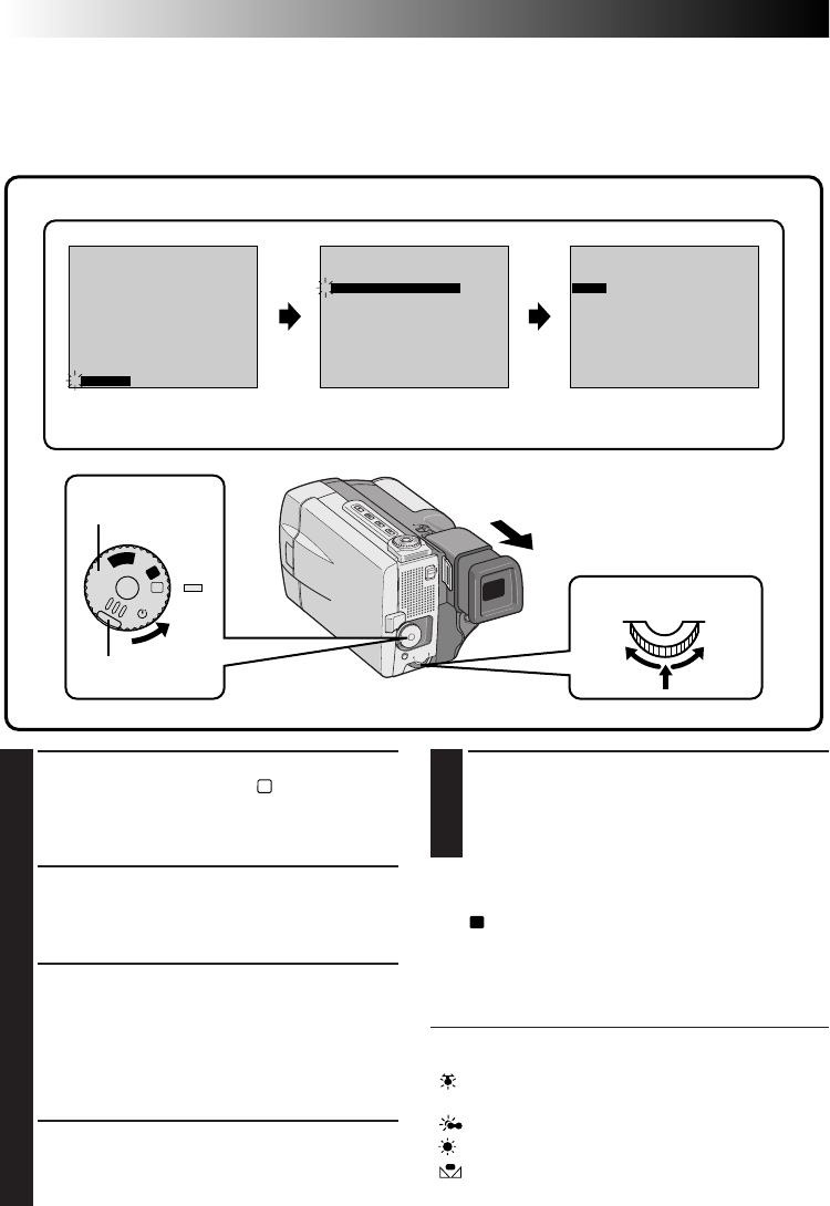
48 EN
White Balance Adjustment
A term that refers to the correctness of colour reproduction under various lighting. If the white balance is
correct, all other colours will be accurately reproduced.
The white balance is usually adjusted automatically. However, the more advanced camcorder operator
would prefer to control this function manually and achieve a more professional colour/tint reproduction.
FOCUS
EXPOSURE AUTO
OFF
OFF
AUTO
AUTO
W. BALANCE
FADER
/ WIPE
P. AE
/ EFFECT
RETURN
4
FOCUS
EXPOSURE AUTO
OFF
OFF
AUTO
AUTO
W. BALANCE
FADER
/ WIPE
P. AE
/ EFFECT
RETURN
4
W . BAL .
AUTO
A
M
5S
OFF
P
L
A
Y
1
SELECT OPERATION MODE
First turn the Power Dial to “
M
” while pressing
down the lock button located on the dial,
make sure the LCD monitor is open fully or the
viewfinder is pulled out.
2
ACCESS MANUAL MODE ITEM
MENU
Press the Select Dial. The Manual Mode Item
Menu appears.
3
ACCESS WHITE BALANCE ADJUST-
MENT
Move the pointer and highlight bar to
“W.BALANCE” by rotating the Select Dial.
Then press it. The Manual Mode Item menu
disappears and “W.BAL.” appears in the upper
left corner and “AUTO” appears on the screen.
4
SET FUNCTION PARAMETERS
Cycle through the available settings of the
selected functions by rotating the Select Dial,
and stop when the one you want is displayed.
5
CLOSE WHITE BALANCE ADJUST-
MENT
Press the Select Dial again. Selection is
complete. The indication “W. BAL.” changes to
“MANUAL”.
To Return To Automatic White Balance . . .
.... select “AUTO” in step 3. Or set the Power Dial to
“
A
”.
NOTE:
White balance cannot be used when P.AE/Effects
Sepia or Monotone are activated.
AUTO–The white balance is adjusted automatically.
This is the factory preset position.
“”– When using a video light or other similar
type of lighting.
“”– When shooting outdoors on a cloudy day.
“ ”– When shooting outdoors on a sunny day.
“”– When shooting with the white balance
already having been set on the subject
(Z pg. 49).
Display
Manual Mode Item Menu White Balance Adjustment
Power Dial
Lock button
Select Dial
RECORDING
Advanced Features (Cont.)
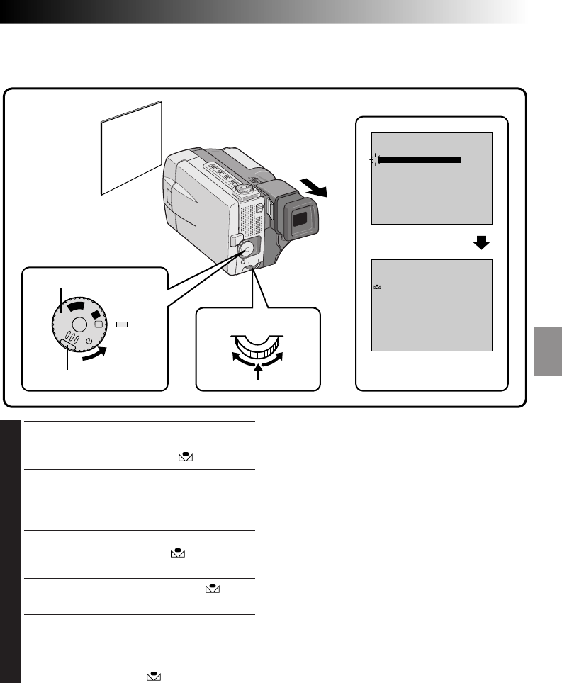
EN 49
FOCUS
EXPOSURE AUTO
OFF
OFF
AUTO
AUTO
W. BALANCE
FADER
/ WIPE
P. AE
/ EFFECT
RETURN
4
PAUSE
MANUAL
A
M
5S
OFF
P
L
A
Y
To Change The Tint For Recording . . .
.... In step 2, substitute coloured paper for white. The
white balance is adjusted based on the colour,
changing the tint. Red paper — deeper green;
blue paper — orange; yellow paper — deeper
purple.
NOTES:
●
A subject can be shot under various types of
lighting conditions indoors (natural, flourescent,
candlelight, etc.). Because the colour temperature
is different depending on the light source, the tint
of the subject will differ depending on the white
balance settings. Use this function for a more
natural result.
●
Once you adjust white balance during Manual
White Balance operation, the setting is retained
even if the power is turned off or the battery
removed.
Manual White Balance Operation
If the camera is operating in manual mode, perform a Manual White Balance when shooting under various
types of lighting
1
SELECT OPERATION MODE
Follow steps 1 through 4 of the white balance
adjustment (Z pg. 48), select “ MAN.”.
2
SET MANUAL WHITE BALANCE
Hold a sheet of plain white paper in front of
the subject. Adjust zoom or position yourself
so that the white paper fills the screen.
3
ENTER SETTING
Press the Select Dial until the begins
blinking.
•When the setting is completed, the stops
blinking.
4
EXIT MANUAL WHITE BALANCE
ADJUSTMENT
Press the Select Dial. The indication “W.BAL.”
changes to “MANUAL” and only the Manual
White Balance indicator is displayed.
Display
Manual Mode
Item Menu
Power Dial
White paper
Manual White Balance
Adjustment
Lock button
Select Dial
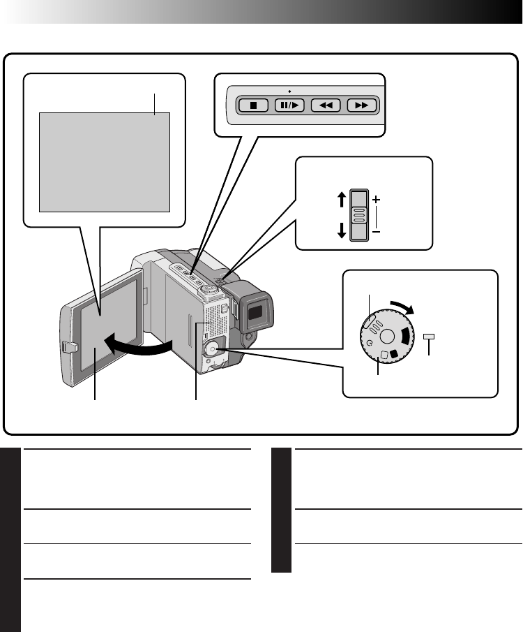
50 EN
W
T
4
VOL.
A
M
5S
OFF
P
L
A
Y
You can watch what you’ve recorded in the LCD monitor.
1
SELECT OPERATION MODE
Turn the Power Dial to “PLAY” while pressing
down the lock button located on the dial. The
Power lamp comes on.
2
OPEN LCD MONITOR
Open the LCD monitor.
•When the viewfinder is pulled out, the LCD
monitor cannot be used.
3
REWIND TAPE
Press
2
.
2
is displayed. If you rewind all
the way to the end of the tape, it stops
automatically.
PLAYBACK
Basic Playback
Power Dial
Lock button
Tape running indicator
LCD monitor
Power lamp
Speaker
Volume switch
4
VIEWING RECORDING
Press 6/
4
.
4
appears and the recorded
footage can be viewed. The sound is heard
from the speaker.
5
END PLAYBACK
Press 5. Set the Power Dial to “OFF”.
•When turning to “OFF”, it is not necessary to
press down the lock button.

EN 51
To Perform High-Speed Search . . .
.... press
2
or
3
after pressing 6/
4
. The tape
will move at approximately 9 times the normal
playback speed. Watch in the LCD monitor and,
when you reach the spot you want to see, press
6/
4
and normal playback resumes.
.... during playback, press and hold
2
or
3
. The
search continues as long as you hold the
button. Once you release it, normal playback
resumes.
.... a slight mosaic effect appears on screen during
High-Speed Search. This is not a malfunction.
Playback Sound
You can hear sound from the speaker or using
headphones connected to the headphones connector
during playback. To adjust the sound volume, slide
the VOL. switch. The sound volume indication is
displayed. Slide the VOL. switch towards “+” to turn
up the volume, or towards “–” to turn it down.
Still Playback
To temporarily stop playback, press 6/
4
. Press
again to resume playback. If still playback contin-
ues for more than about 3 minutes, the camcorder’s
Stop mode is automatically engaged. After 5
minutes in the stop mode, the camcorder’s power is
automatically turned off.
Slow-Motion Playback
●To perform Slow-motion playback, the remote
control is necessary.
●To change from normal to slow-motion playback,
press the Pause button at the point where you
want to start playback in slow motion, point the
remote control at the remote sensor, and press the
remote’s Slow Rewind or Slow Forward button.
After playing back in slow motion for about 10 to
20 seconds, normal playback resumes. Speed is 1/
10 times normal. To stop slow-motion playback in
progress, press the Play button.
●During slow-motion playback, due to digital
image processing, the picture may take on a
mosaic effect.
●After the Slow Rewind or Slow Forward button is
pressed, the still image may be displayed for a
few seconds, then the screen may become blue
back for a few seconds. This is not a malfunction.
●There may be a small margin between the slow-
motion playback start point you chose and the
start point at which the camcorder actually begins
playback in slow motion.
NOTES:
●
The sound is not available during High-Speed
Search.
●
Copy guarded tapes cannot be played back. The
screen becomes blue back.
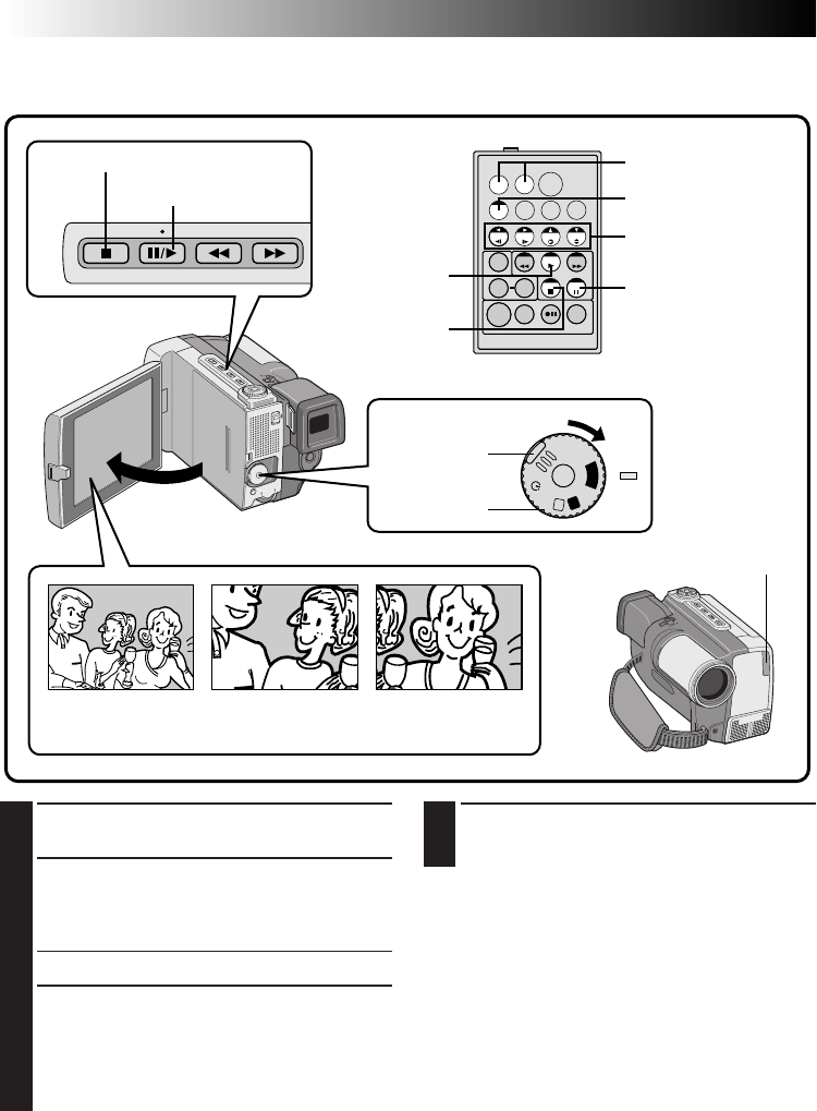
52 EN
TW
A
M
5S
OFF
P
L
A
Y
4
END ZOOM
Press and hold W until magnification returns to
normal. Or, press STOP and then press PLAY.
NOTES:
●
Zoom can also be used during slow-motion and
still playback.
●
If the Video Echo effect (
Z
pg. 53) is selected
during playback zoom, playback zoom is
cancelled.
●
During digital image processing, the quality of the
image may suffer.
1
FIND THE SCENE OF INTEREST
Press the Play button to start playback.
2
ACTIVATE ZOOM
Press the zoom buttons (T/W) on the remote
control. Make sure the remote control is
pointed at the camcorder's remote sensor.
•Pressing T zooms in.
3
LOCATE PORTION OF MAGNIFIED
SCENE
You can move the image on screen around to
find a particular portion of the picture. While
holding down SHIFT, press § (Left),
© (Right), ¶ (Up) and Ä (Down).
Playback Zoom
The recorded pictures can be magnified up to 10X at any time during playback.
Press T Press © (Right) to
move image
Normal playback
PAUSE
Left/Right/Up/
Down buttons
Zoom buttons
SHIFT
STOP
PLAY
PLAYBACK
Advanced Features
Lock button
RM-V711U
(provided)
Power Dial
Play button
Remote sensor
Stop button
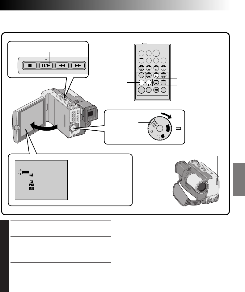
EN 53
TW
P. AE / EFFECT
STROBE
VIDEO ECHO
CLASSIC FILM
MONOTONE
SEPIA
4
5
1
2
3
OFF
4
B
/
W
A
M
5S
OFF
P
L
A
Y
1
START PLAYBACK
Press the Play button (
4
).
2
ACCESS P.AE/EFFECT SELECT MENU
Point the remote control at the camcorder’s
remote sensor and press EFFECT. The P.AE/
EFFECT Select Menu appears.
3
SELECT P.AE/EFFECT
Move the pointer and highlight bar to the
desired effect by pressing EFFECT. The selected
function is activated and after 2 seconds the
menu disappears.
NOTES:
●
To deactivate the selected effect, press EFFECT
ON/OFF on the remote control. Pressing it again
re-activates the selected effect.
●
Repeat from step 2 when you want to change the
selected effect.
●
When a Playback Effect is activated, Pro Snapshot
modes (
Z
pg. 29) are not possible.
The effects that can be used during playback are
Classic Film, Monotone, Sepia, Strobe and Video
Echo
. The effects work the same in playback as they
did in recording. Refer to page 43 for more
information.
Playback Effects
These effects allow you to be creative with the playback picture. You can use any one of the 5 effects.
EFFECT EFFECT ON/OFF
P.AE/EFFECT Select Menu
(Playback)
PLAY
Lock button
RM-V711U
(provided)
Power Dial
Remote sensor
Play button
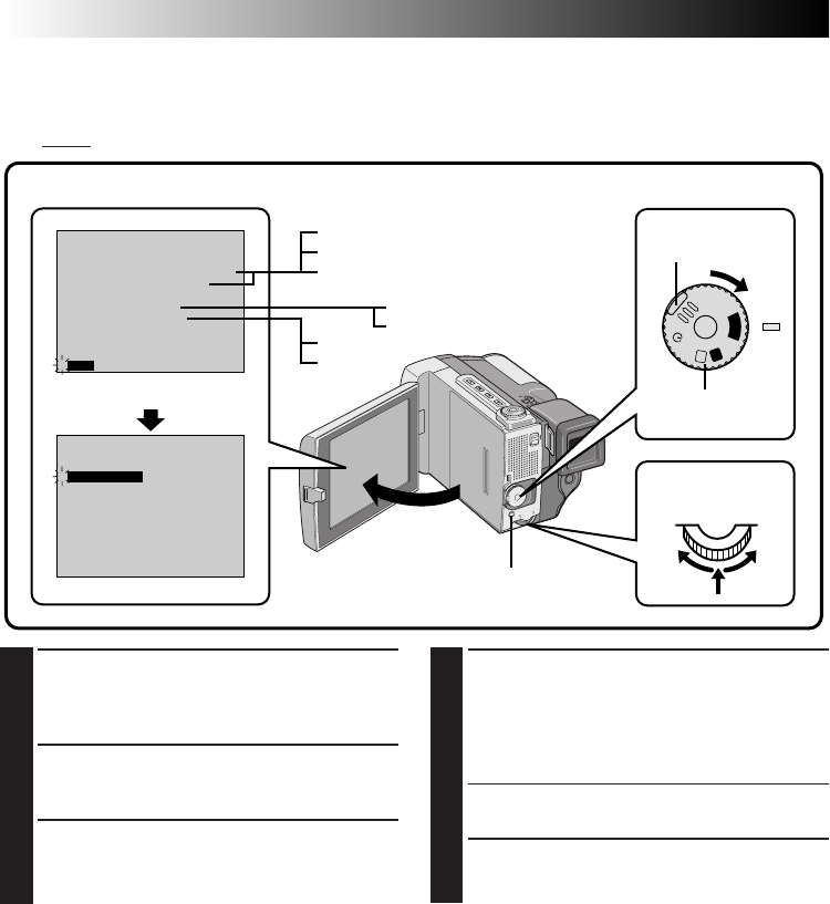
54 EN
PLAYBACK
Advanced Features (Cont.)
SOUND1
0 . 0
ON
OFF ON
OFF
ON
OFF
FULL SOUND
SOUND2
SOUND1
FULL SOUND
48kHz MODE
32kHz MODE
DISPLAY
TIMECODE
SYNCHRO
END
4
SOUND1
0 . 0
ON
OFF
FULL SOUND48kHz MODE
32kHz MODE
DISPLAY
TIMECODE
SYNCHRO
END
4
A
M
5S
OFF
P
L
A
Y
Playback Menu
The Playback Menu allows you to set the following functions:
Playback Sound (32 kHz, 48 kHz), Synchro Comp, Display
and
Time Code
. The following procedure applies
to all except
Synchro Comp
(Z pg. 66, 67).
4
SET FUNCTION PARAMETERS
Rotate the Select Dial to cycle through the
available settings for the selected function, and
stop when the desired setting appears. Then
press the Select Dial, and the pointer and
highlight bar automatically move to “END”.
•To set parameters for other functions, repeat
steps 3 and 4.
5
CLOSE MENU
Press the Select Dial again, and the menu
disappears.
1
SELECT OPERATION MODE
First turn the Power Dial to “PLAY” while
pressing down the lock button located on the
dial. Open the LCD monitor fully.
2
ACCESS PLAYBACK MENU
Press MENU. The Playback Menu appears in
the LCD monitor and on the connected TV.
3
SELECT FUNCTION
Move the pointer and highlight bar to the
desired function by rotating the Select Dial.
Press the Select Dial to activate.
Playback Menu
Display
Power Dial
Lock button
Select Dial
MENU button
EN 55
RECORDING SOUND DISPLAY OUTPUT SOUND
32 kHz FULL SOUND
SOUND 1 Stereo sound
SOUND 2
48 kHz FULL SOUND Stereo sound
SOUND 1 “L” sound is output on both channels
SOUND 2 “R” sound is output on both channels
Playback Sound
During playback, the camcorder detects the sound mode in which the recording was made, and plays the
sound back. Select the type of sound to accompany your playback picture. (32 kHz is preset to “SOUND 1”
and 48 kHz is preset to “FULL SOUND”.)
When watching a tape recorded at 32 kHz, if you want to change the output sound, access the Playback
Menu and, in step 3 on page 54, select “32kHz MODE” and set it for “FULL SOUND”, “SOUND 1” or
“SOUND 2”. When playing back a tape recorded at 48kHz, set in the same manner. For information on
output sound during Audio Dubbing, see page 68.
NOTES:
●
You can also use the RM-V711U remote control’s AUDIO MONITOR Button to change the output sound
(without having to access the Playback Menu). Make sure you point the remote control at the camcorder’s
remote sensor.
●
During playback, the camcorder detects the sound mode in which the recording was made. This detection
cannot be made during fast-forward or rewind. During playback the sound mode is displayed in the upper
left corner.
TIME CODE
(Displaying The Time Code During Playback)
You can display the Time Code on screen during
playback. This is especially useful for editing. This
function is preset to “OFF”. To turn it on, select
“TIME CODE” at the Playback Menu and change
the setting (Z pg. 54).
ON– The Time Code is displayed on the playback
screen.
OFF–The Time Code does not appear.
DISPLAY
(Displaying the Date During Playback)
If the time has been set, the date is automatically
recorded separately from the recorded video signal.
You can display or remove the date anytime during
playback. This function is preset to “ON”. To turn it
off, select “DISPLAY” at the Playback Menu and
change the setting (Z pg. 54).
ON– The date is displayed on the playback screen.
OFF–The date is not displayed.
TC 12 : 34 : 24 25 . 12 . 98
10 : 35
Display
Minutes
Seconds
Frames*
*25 frames = 1 second
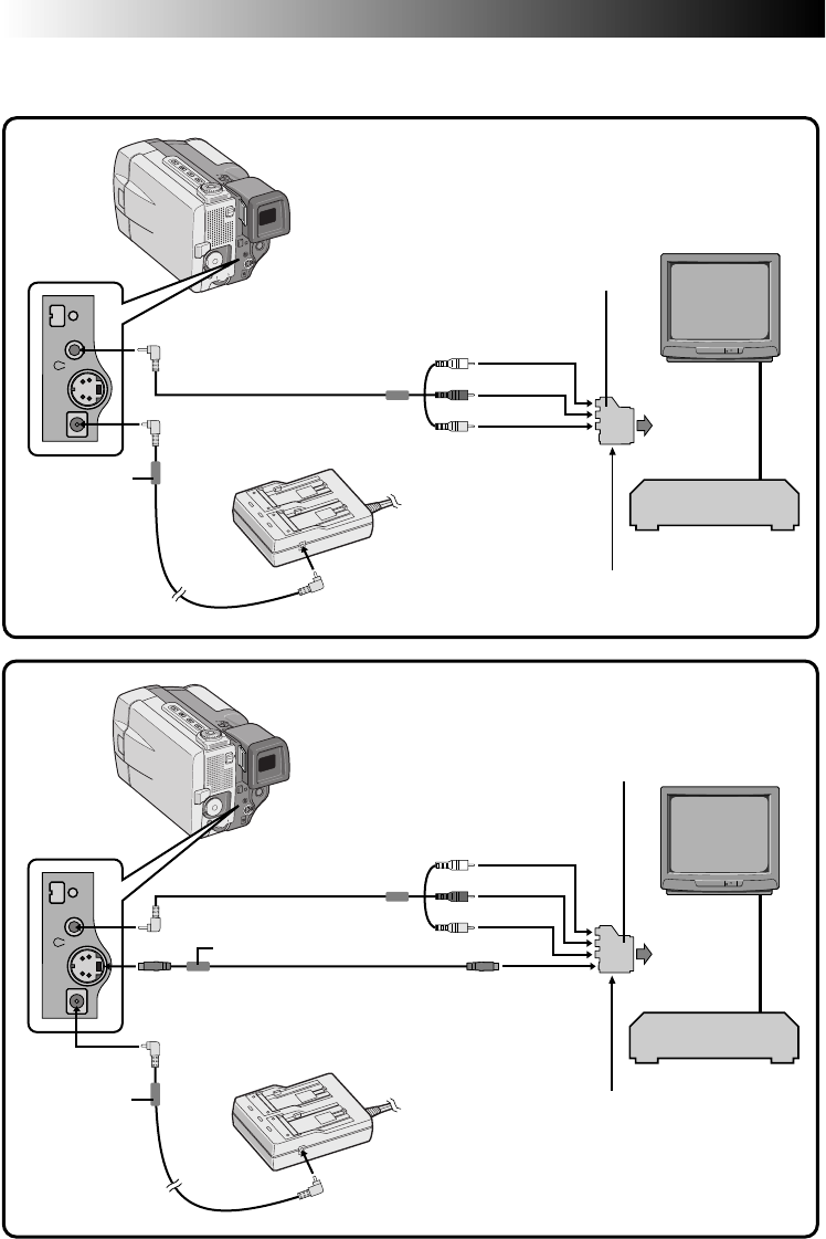
56 EN
PLAYBACK
Basic Connections
VCR/TV Connection
Please refer to your VCR and/or TV instruction manual(s) when connecting.
1
Yellow to VIDEO
White to AUDIO L
Red to AUDIO R
2
DC cord AC Power
Adapter/Charger
VIDEO/AUDIO
cable (provided)
To DC OUT jack
AC Power
Adapter/Charger
VCR
Core filter
Connection to a TV or VCR equipped with a
SCART connector compatible only with
regular video signal
Connection to a TV or VCR equipped wiht a
SCART connector compatible with Y/C signal
To VIDEO IN
connector
To AV OUT connector
To DC IN jack
To AUDIO IN
connector (L/R)
VIDEO OUT select switch
(Set to CVBS)
VCR
Cable adapter
(provided only with U.K. models)
Core filter
To AUDIO IN connector
(L/R)
To VIDEO IN connector
To S-VIDEO OUT
connector To S-VIDEO IN
connector
To DC IN jack
DC cord
Core filter
To
TV or VCR
To
TV or VCR
VIDEO OUT select switch (set to Y/C)
Cable adapter
(provided only with U.K. models)
S-VIDEO cable
(provided)
VIDEO/AUDIO
cable (provided)
To AV OUT connector
To DC OUT jack
Connector is
under the cover.
Connector is
under the cover.
Yellow to VIDEO
White to AUDIO L
Red to AUDIO R
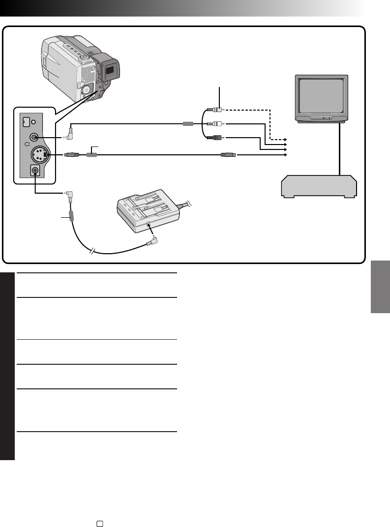
EN 57
3
1
CONFIRM POWER-OFF STATUS
Make sure the camcorder’s power is off.
2
CONNECT CAMCORDER TO TV OR VCR
Pull out the connector cover and open it.
Connect as shown in the illustration 1, 2 or 3
(Z pg. 56, 57).
If Using A VCR . . . go to step 3.
If not . . . go to step 4.
3
CONNECT VCR OUTPUT TO TV INPUT
Refer to your VCR’s instruction manual.
4
TURN ON POWER
Turn the Power Dial to “PLAY” while pressing
down the lock button located on the dial and
turn on the TV/VCR.
5
SELECT TV’S VIDEO MODE
Set the TV to the channel or mode appropriate
for video playback.
To choose whether or not the following displays
appear on the connected TV . . .
•Date/Time, Time Code
.... set to “ON” or “OFF” in the Playback Menu
(Z
pg. 54).
•Playback Sound Mode Display
.... set the Power Dial to “
M
”, press the MENU
button, and set “ON SCREEN” in the Date/
Time Menu (Z
pg. 11) to “ON” or “OFF”.
Then set the Power Dial back to “PLAY”.
Connection to a TV or VCR equipped with an
S-VIDEO IN and/or A/V input (RCA type)
connectors
AC Power
Adapter/Charger
VCR
NOTES:
●
Never connect any other VIDEO/AUDIO cable
than the provided VIDEO/AUDIO cable to the
camcorder’s AV OUT connector.
●
When using the provided DC cord, S-VIDEO
cable or editing cable, make sure you connect the
end of the cable with the core filter to the
camcorder. The core filter improves performance
of equipment.
●
If TV/VCR is equipped with only one audio
connector, use a conversion plug (commercially
available).
●
Make sure you adjust the TV sound volume to its
minimum level to avoid a sudden burst of sound
when the camcorder is turned on.
●
To keep the camcorder's display from appearing
on the TV screen during playback, press the ON/
OFF button for longer than 1 second.
●
For customers in the U.K.; Set the VIDEO OUT
select switch of the cable adapter as required:
Y/C: When connecting to a TV or VCR which
accepts Y/C signals and uses an S-VIDEO cable.
CVBS: When connecting to a TV or VCR which
does not accept Y/C signals and uses an audio/
video cable.
●
While the VIDEO/AUDIO cable is connected to
the AV OUT jack, sound cannot be heard from
the speaker.
To DC OUT jack
DC cord
Core filter
Core filter
Connect when the
S-VIDEO cable is not used
S-VIDEO cable
(provided)
To S-VIDEO
OUT connector
To AV OUT connector
To DC IN jack
To
TV or VCR
VIDEO/AUDIO
cable (provided)
To S-VIDEO IN
connector
To VIDEO IN
connector
To AUDIO IN
connector (L/R)
Yellow to VIDEO
White to AUDIO L
Red to AUDIO R
Connector is
under the cover.
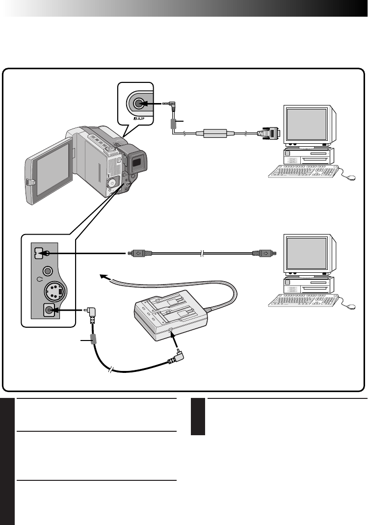
58 EN
PLAYBACK
Advanced Connections
4
TURN ON POWER
Turn the camcorder's Power Dial to "PLAY"
while pressing down the lock button located
on the dial and turn on the PC.
NOTES:
●
When transferring still images, never use the
battery pack installed in the camcorder as the
power supply. Use the provided AC Power
Adapter/Charger.
●
Never connect the JLIP-PC connection cable and
the DV cable simultaneously to the camcorder.
Connect only the cable you wish to use to the
camcorder.
●
The date/time information cannot be captured into
PC.
●
Also refer to the instruction manuals of the provided
Software and the DV connector-equipped capture
board.
Connection To A Personal Computer
This camcorder can transfer still images to a personal computer by using the provided software when
connected as shown in the illustration below. It is also possible to transfer still images to a personal compu-
ter with a DV connector-equipped capture board installed.
1
CONFIRM POWER-OFF STATUS
Make sure the camcorder and PC are turned
off.
2
CONNECT CAMCORDER TO PC
Pull out the connector cover and open it.
Connect the camcorder to a PC using the cable
according to your PC type as shown in the
illustration.
3
SUPPLY POWER
Connect the camcorder to the AC Power
Adapter/Charger using the DC cord, then plug
the AC Power Adapter/Charger's power cord
into an AC outlet.
JLIP (DIGITAL STILL)
output connector
To RS-232C
To AC outlet
JLIP-PC connection cable
(provided)
DV cable (optional) To DV
connector
AC Power
Adapter/Charger
(provided)
To DC OUT jack
PC with DV
connector-
equipped
capture board
To DV OUT
connector
PC
To DC IN
jack
DC cord
Core filter
Core filter
Connector is
under the cover.
Connector is under
the cover.
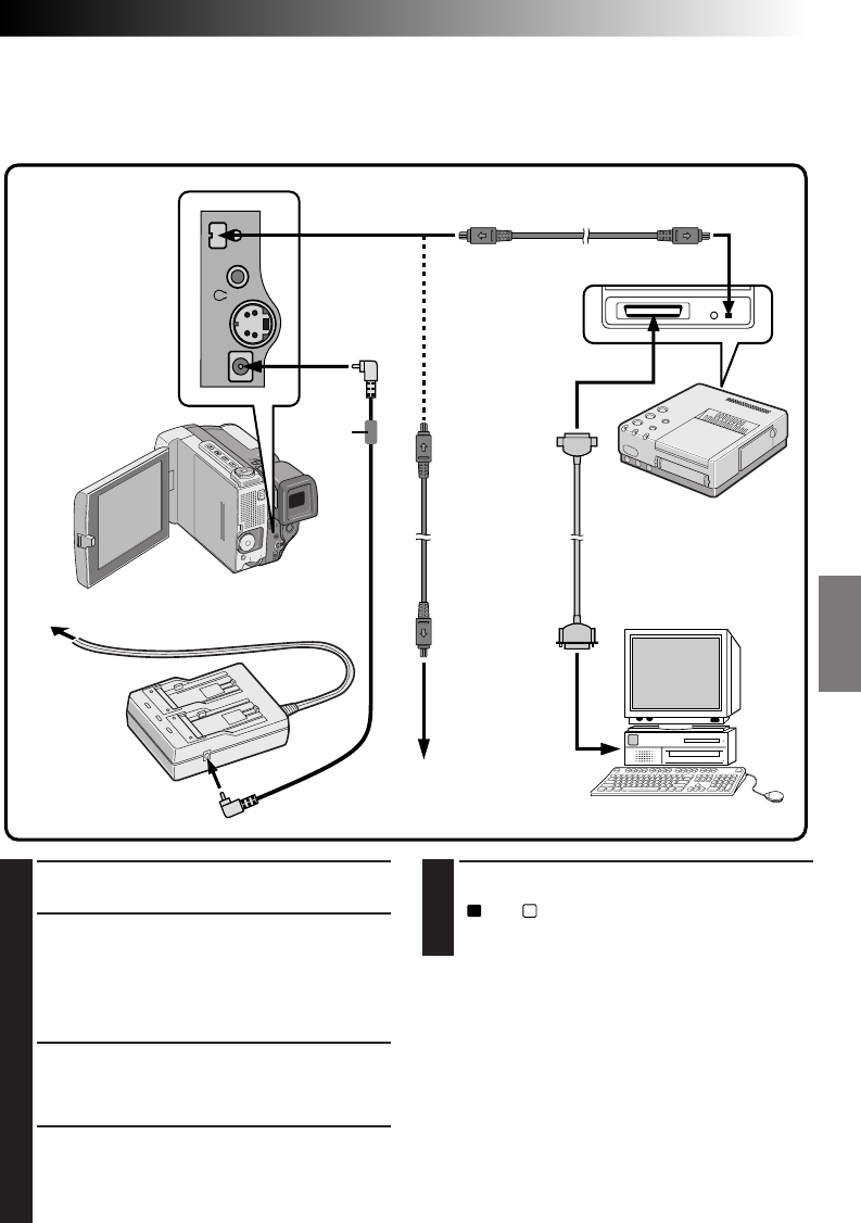
EN 59
To DV OUT
connector
To PARALLEL
(PRINTER)
connector
To DC IN jack
To DC OUT jack
AC Power
Adapter/
Charger
To DV
connector
DV cable
(optional)
Digital Printer
To PARALLEL connector
To DV OUT
connector
To
DV IN connector
To AC outlet
Video unit equipped with
a DV input connector
Printer cable
(commercially available)
2 way-Parallel Interface
PC
5
TURN ON POWER
Turn the camcorder's Power Dial to “PLAY”,
“
A
” or “
M
” while pressing down the lock
button located on the dial and turn on the
other units.
NOTES:
●
You cannot use the battery pack installed in the
camcorder as the power supply since a digital
signal is output from the DV OUT connector only
when using the AC Power Adapter/Charger.
●
When using the camcorder for dubbing, be sure to
use it as a player. The camcorder's DV connector
is only for output.
●
Also refer to the instruction manuals of the
connected units.
1
CONFIRM POWER-OFF STATUS
Make sure all the units are turned off.
2
CONNECT CAMCORDER TO PRINTER
OR VIDEO UNIT EQUIPPED WITH DV
INPUT CONNECTOR
Pull out the connector cover and open it. Make
connections to the device you want to connect to
using the DV cable, as shown in the illustration.
3
CONNECT PRINTER TO PC
Connect the printer cable to the printer's
PARALLEL connector and the PC's PARALLEL
(PRINTER) connector.
4
SUPPLY POWER
Connect the camcorder to the AC Power
Adapter/Charger using the DC cord, then plug
the AC Power Adapter/Charger's power cord
into an AC outlet.
Connection To A Video Unit Equipped With A DV Connector
Connection to the Digital Printer GV-DT1 (optional) allows you to print out the images or to transfer the
captured image from the Digital Printer to a personal computer. It is also possible to copy recorded scenes
from the camcorder onto another video unit equipped with a DV connector. This function is called Digital
Dubbing (Z pg. 61), which offers virtually no image or sound deterioration.
DV cable (optional)
Core
filter
Connector is
under the cover.
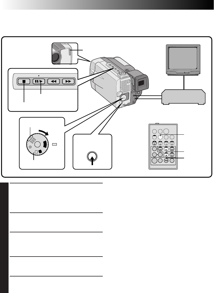
60 EN
TW
A
M
5S
OFF
P
L
A
Y
Dubbing
You can copy recorded scenes from the camcorder onto a videotape. Refer to your VCR’s instruction manual
for details.
NOTES:
●
You can use Playback Zoom (
Z
pg. 52) or
Playback Effects (
Z
pg. 53) in step 2.
●
Before you start dubbing, make sure that the
indications do not appear on the connected TV. If
they do appear during dubbing, they are being
recorded onto the new tape.
To clear the Playback Sound Mode Display, press
DISPLAY on the RM-V711U Remote Control.
●
Select “DISPLAY” and “TIME CODE” from the
Playback Menu (
Z
pg. 54) to show or hide the
Date/Time and the Time Code on the recording.
●
To show or hide all indications, press the
ON/OFF button on the camcorder for longer than
1 second.
1
MAKE CONNECTIONS
Connect the camcorder to your VCR as shown
in the illustration on pages 56, 57.
Please also refer to your VCR's instruction
manual before dubbing.
2
START PLAYBACK
Press the Play button (
4
) to play back the
source tape.
3
START RECORDING
While watching on the connected TV, engage
your VCR’s record mode from the spot on the
source tape you want to begin recording.
4
PAUSE RECORDING
Engage your VCR’s pause mode to stop
recording a segment.
5
END RECORDING
Press the Stop button (5) to stop the source
tape, and engage the VCR’s stop mode.
EDITING
Play button
Stop button
ON/OFF button
PLAY
DISPLAY
STOP
RM-V711U
(provided)
VCR
(Recording deck)
Power Dial
Lock button
Remote sensor
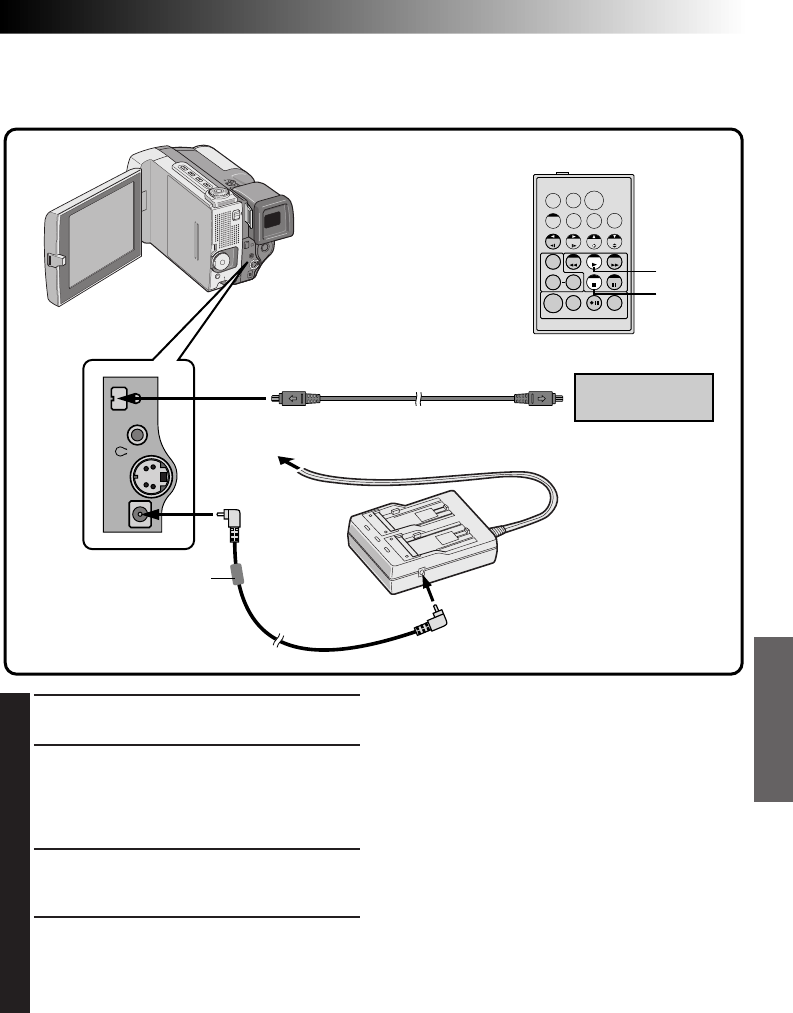
EN 61
TW
Digital Dubbing
It is also possible to copy recorded scenes from the camcorder onto other video unit equipped with a DV
connector. Since digital signal is sent, there is little if any image or sound deterioration.
NOTES:
●
You cannot use the battery pack installed in the
camcorder as the power supply since a digital
signal is output from the DV OUT connector only
when using the AC Power Adapter/Charger.
●
When using the camcorder for dubbing, be sure
to use it as a player. The camcorder's DV
connector is only for output.
●
If a blank portion is played back during dubbing,
an unusual image may be dubbed.
●
Even though the DV cable is connected correctly,
sometimes the image may not appear in step 3. If
the above occurs, turn off power and make
connections again. 1
●
The image with Fade/Wipe Effects and P.AE/
Effects is not output from the DV OUT connector.
Only the original playback image is output from
it.
1
CONFIRM POWER-OFF STATUS
Make sure the camcorder's power is off.
2
MAKE CONNECTIONS
Pull out the connector cover and open it.
Connect the camcorder to your video unit
equipped with a DV connector using the DV
cable (optional) as shown in the illustration.
3
START PLAYBACK
Press the Play button (
4
) to play back the
source tape.
4
START RECORDING
While watching the playback on the LCD
monitor, engage the DV connector-equipped
video unit's record mode from the spot on the
source tape you want to begin recording.
AC Power
Adapter/Charger
DC cord
Video unit equipped
with DV connector
RM-V711U
(provided)
To DV
connector
To DV OUT
connector DV cable (optional)
PLAY
STOP
To AC outlet
Core filter
To DC IN jack
To DC OUT jack
Connector is
under the cover.
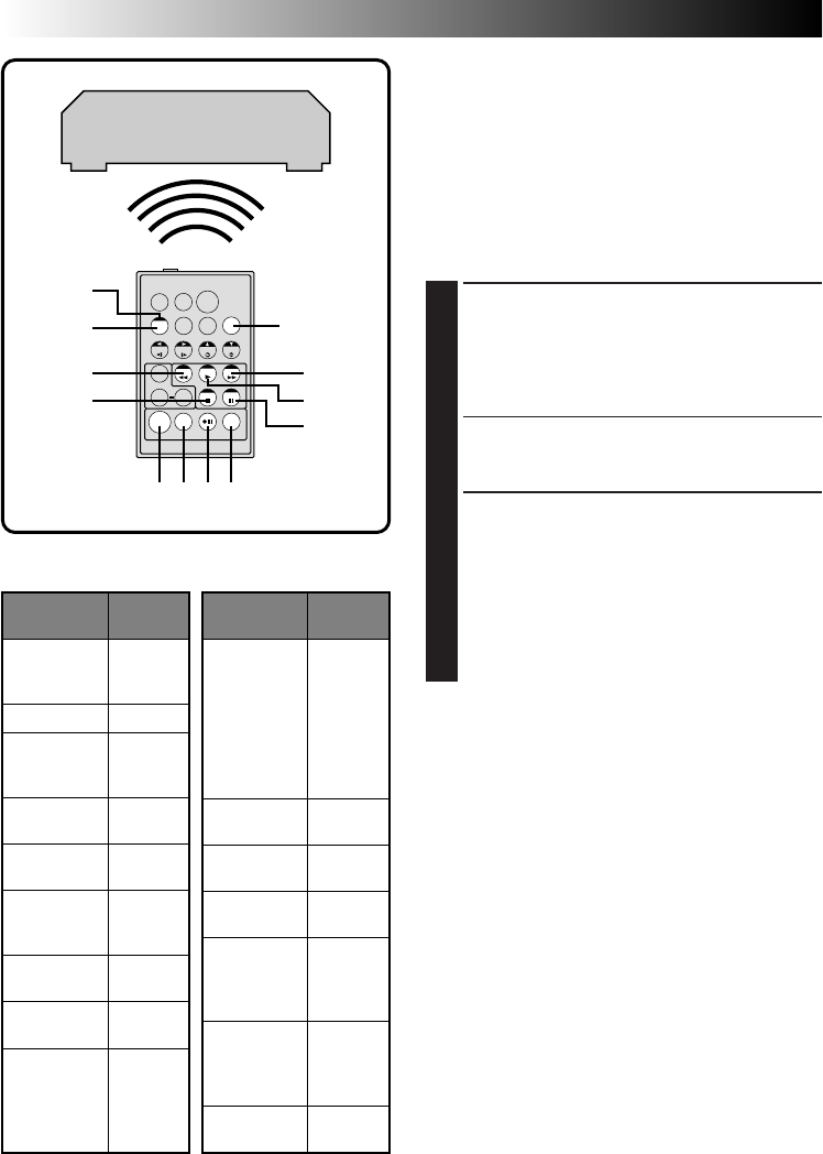
62 EN
TW
3
1
6
789`
5
4
2
VCR CODE LIST
VCR BRAND
NAME
BUTTONS
(A) (B)
6 2
6 4
7 7
MITSUBISHI 6 7
6 8
NEC 3 7
3 8
GRUNDIG 1 4
3 4
HITACHI 6 6
6 3
PANASONIC 1 3
1 7
1 1
9 4
1 8
JVC 9 1
9 6
9 3
BLAUPUNKT
AKAI
9 7
9 8
3 2
FERGUSON
1 3
VCR BRAND
NAME
BUTTONS
(A) (B)
SANYO 3 6
3 5
SHARP 1 5
1 `
TOSHIBA 6 9
6 1
SONY 6 5
6 `
3 9
3 1
THOMSON,
TELEFUNKEN,
SABA,
NORDMENDE
9 1
9 6
9 7
3 2
SELECO,
REX
9 1
9 6
PHILIPS 1 9
9 5
1 1
9 4
9 1
9 6
1 2
3 3
A
B
C
MBR SET
SHIFT
RM-V711U
(provided)
Brand Setting
Before you can perform Random Assemble Editing
(Z pg. 63 – 65), or control the VCR using the
RM-V711U remote control, you must set the VCR
brand.
SET REMOTE/VCR CODE
Before operation, make sure the lithium battery is
installed in the remote control RM-V711U
(Z pg. 16).
1
SET REMOTE TO OPERATE VCR
Turn off the power to the VCR and point the
remote towards the VCR’s infrared sensor.
Then, referring to the VCR CODE LIST on the
left, press and hold MBR SET, and press button
(A) and then (B).
•The code is automatically set once you
release the MBR SET button, and the VCR’s
power comes on.
2
OPERATE THE VCR
Make sure the VCR’s power is on. Then, while
holding SHIFT, press the button on the remote
for the desired function. The functions the
remote can control are PLAY, STOP, PAUSE, FF,
REW and VCR REC STBY (you don’t need to
press SHIFT for this one).
You’re now ready to try Random Assemble
Editing.
IMPORTANT
Although the MBR is compatible with JVC VCRs
and those of many other makers, it may not work
with yours or may offer limited functions.
NOTES:
●
If the VCR’s power doesn’t come on in step 1, try
another code from the VCR CODE LIST.
●
Some brands of VCR don’t come on automati-
cally. In this case, turn the power on manually
and try step 2.
●
If the RM-V711U is not able to control the VCR,
use the controls on the VCR.
●
When the remote control's battery runs out, the
VCR brand you have set will be erased.
In that case, replace the old battery with a new
one to reset the VCR brand.
VCR (Recording deck)
EDITING
(Cont.)
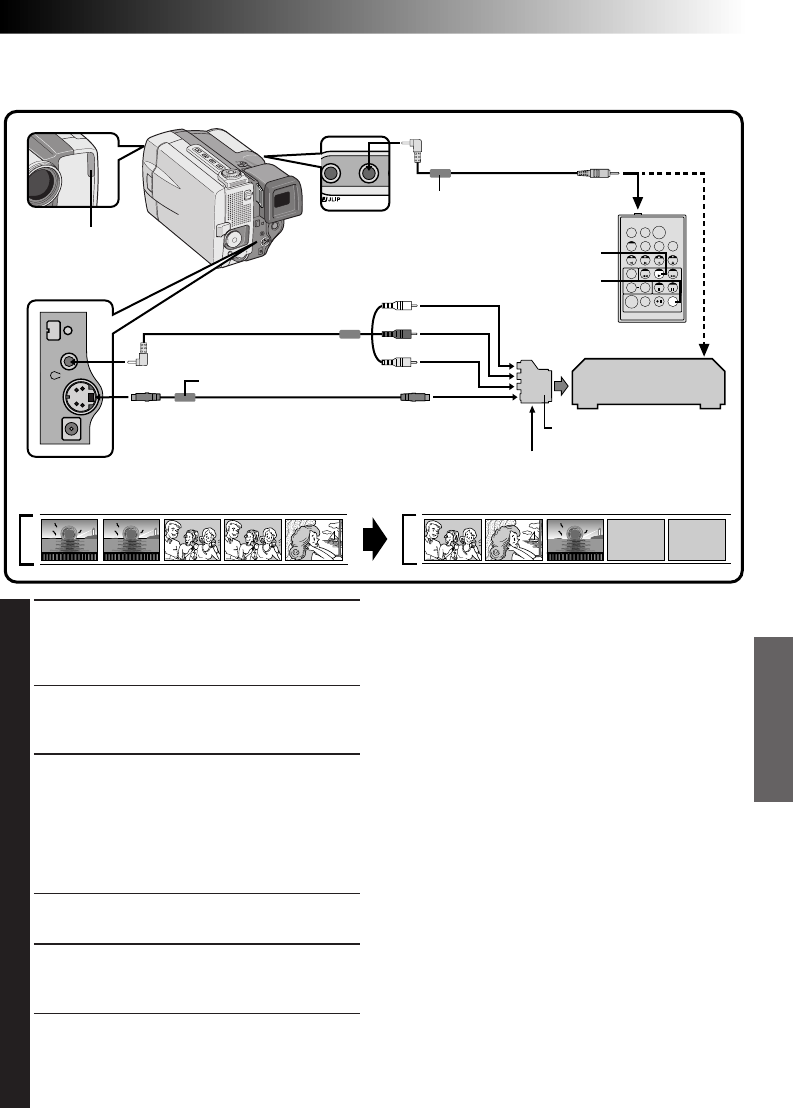
EN 63
TW
Random Assemble Editing
Using the RM-V711U remote control, you can use P.AE/Effects and make an original edited tape.
1
MAKE CONNECTIONS
Make sure that the playback picture and sound
are available on the connected TV (Z pg. 56,
57).
•Connections should be made while the power
is off. Making connections with the power on
can lead to electrical shock or malfunctions.
2
START SOURCE PLAYBACK
First turn the Power Dial to “PLAY” while
pressing down the lock button located on the
dial. Press PLAY and then press R.A. EDIT ON/
OFF on the remote control. Make sure to point
the remote control at the camcorder’s remote
sensor.
•The Random Assemble Editing Menu appears
on the TV screen or the LCD monitor.
3
EXECUTE FADE/WIPE IN
(IF NECESSARY)
Press FADE/WIPE on the remote control.
•Cycle through the effects by pressing
repeatedly, and stop when the one you want
is displayed.
•You can’t use a Picture Wipe/Dissolve at the
beginning of Program 1.
Source tape (Camcorder) New tape (VCR)
NOTES:
●
When using a JVC VCR with a remote pause
terminal, connect the EDIT jack on the camcorder to
the VCR’s remote pause terminal using an editing
cable.
●
If you use a JVC VCR not equipped with a remote
pause terminal or a non-JVC VCR, connect the
camcorder's EDIT jack to the remote control's remote
pause connector using an editing cable.
●
For customers in the U.K.; Set the VIDEO OUT select
switch of the cable adapter as required:
Y/C: When connecting to a TV or VCR which accepts
Y/C signals and uses an S-VIDEO cable.
CVBS: When connecting to a TV or VCR which does
not accept Y/C signals and uses an audio/video
cable.
●
Before Random Assemble Editing, make sure the
indications don't appear on the TV monitor. If they
appear during Random Assemble Editing, they will be
recorded onto the new tape. To clear the Playback
Sound Mode Display, press DISPLAY on the RM-
V711U Remote Control. Select “DISPLAY” and “TIME
CODE” from the Playback Menu (
Z
pg. 54) to show
or hide the Date/Time and the Time Code on the
recording. To show or hide all indications except for
the Random Assemble Editing Menu, press ON/OFF
on the camcorder for longer than 1 second. When
Random Assemble Editing starts, its indications
disappear and are not recorded on the new tape.
VCR
(Recording deck)
To remote
pause connecter
To AV OUT connector To
VIDEO IN
connector
To S-VIDEO
IN connector Cable adapter (provided
only with U.K. models)
If your VCR has the 21-pin
AV input connector (SCART),
use the provided cable
adapter.
To AUDIO IN
connector (L/R)
To EDIT jack
Core filter
Remote sensor
To S-VIDEO OUT
connector
VIDEO OUT select switch (Y/C or CVBS)
RM-V711U
Editing cable
(provided)
PLAY
R.A. EDIT
ON/OFF
VIDEO/AUDIO cable
(provided)
S-VIDEO cable
(provided)
Core filter
CONTINUED ON NEXT PAGE
Yellow to VIDEO
White to AUDIO L
Red to AUDIO R
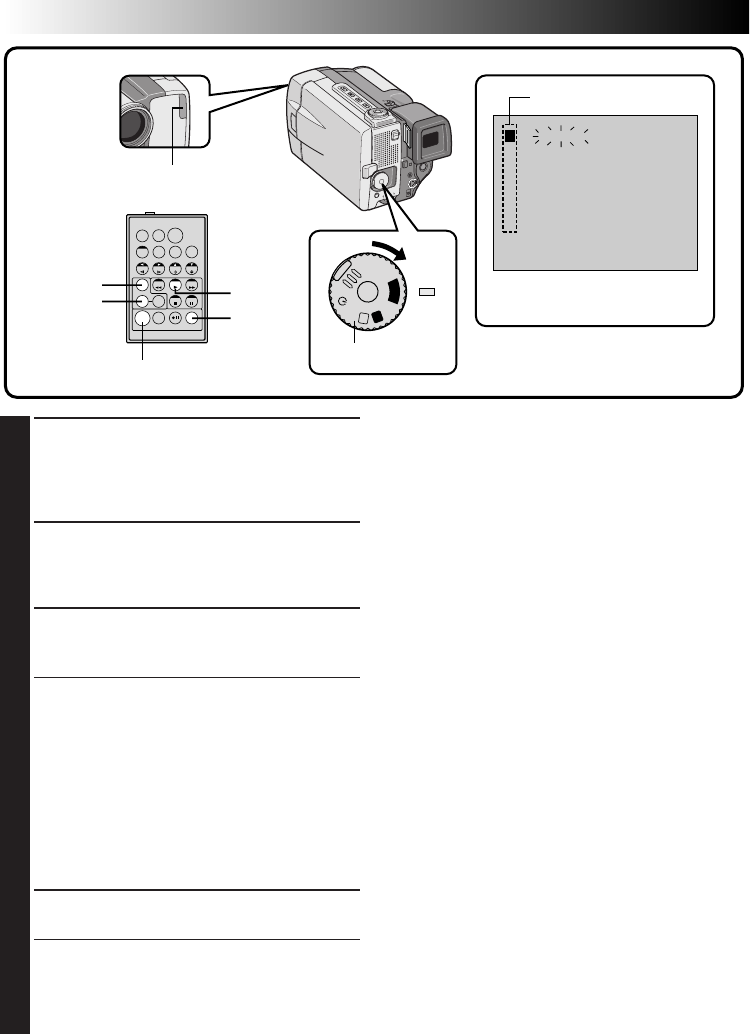
64 EN
TW
1 –– –– : ––
~
2
~
3
~
4
~
5
~
6
~
7
~
8
~
TIME CODE
IN OUT MODE
–– : ––
00 : 00
TOTAL
A
M
5S
OFF
P
L
A
Y
4
SET EDIT-IN POINT
At the beginning of the scene, press EDIT IN/
OUT on the remote control. The Edit-In
position appears on the Random Assemble
Editing Menu.
5
SET EDIT-OUT POINT
At the end of the scene, press EDIT IN/OUT.
The Edit-Out position appears on the Random
Assemble Editing Menu.
6
USE FADE WIPE ON SCENE
TRANSITION (IF NECESSARY)
Press FADE/WIPE.
•Cycle through the effects by pressing
repeatedly, and stop when the one you want
is displayed.
•If you select a Fade/Wipe effect for an
Edit-Out point, the effect is automatically
applied to the following Edit-In point.
•You can’t use a Picture Wipe/Dissolve at the
end of the last scene.
•When you use Fade/Wipe effects, that time is
included in the total time (this does not apply
to Picture Wipe/Dissolve).
7
USE P.AE/EFFECT (IF NECESSARY)
Press EFFECT.
•Cycle through the effects by pressing
repeatedly, and stop when the one you want
is displayed.
•You can use Classic Film, Monotone, Sepia,
Strobe or Video Echo effects.
NOTES:
●
When the source tape has more than 2 identical
time codes (
Z
pg. 21), the camcorder may not
find the Edit-In point you chose and a malfunc-
tion may occur.
●
When choosing a scene, set Edit-In and Edit-Out
points so that there’s a relatively large difference
between them.
●
If the search time for an in-point exceeds 5
minutes, the recording deck’s Record-Standby
mode will be cancelled and editing will not take
place.
●
If there are blank portions before or after the
Edit-In and Edit-Out points, a blue-backed screen
may be included in the edited version.
●
Since time codes register time only as accurately
as seconds, the time code total time may not
match the total program time exactly.
●
Turning off the camcorder’s power erases all
registered Edit-In and Edit-Out points.
●
If you use Sepia or Monotone P.AE/Effects, you
can’t use the Dissolve or Black & White Fader. In
this case the Dissolve or Black & White indicator
begins blinking. Once the next Edit-In point is
registered, the effect is turned off. To combine
these effects, use Sepia or Monotone during
recording, then use Dissolve or Black & White
Fader during Random Assemble Editing.
●
During Digital Dubbing, Fade/Wipe Effects and
P.AE/Effects are not available.
PLAY
R.A.EDIT
ON/OFF
EDIT IN/OUT
EFFECT
FADE/WIPE Random Assemble
Editing Menu
Program
RM-V711U
(provided)
Power Dial
Remote sensor
EDITING
(Cont.)
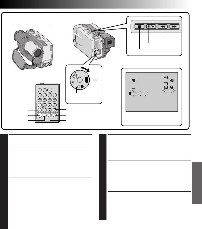
EN 65
TW
4
1 00 : 25
~
02 : 05 ––
2 07 : 18
~
08 : 31 ––
3 –– 03 : 33
~
05 : 53
4 09 : 30
~
13 : 15
5 15 : 55
~
16 : 20 –– ––
6 –– –– : ––
~
7
~
8
~
TIME CODE
IN OUT MODE
16 : 30
9 : 39
TOTAL
W
H
B
/
W
P
P
A
M
5S
OFF
P
L
A
Y
8
REGISTER ADDITIONAL SCENES
Repeat steps 4 – 7 (Z pg. 64).
•To change previously registered points, press
CANCEL on the remote control. The
registered points disappear, one at a time,
from the most recently registered point.
•If you're not using Fade/Wipe or P.AE/Effects,
repeat steps 4 and 5 only.
9
PREPARE SOURCE TAPE
Rewind the tape in the camcorder to the
beginning of the scene you want to edit and
press the Pause button (6).
10
ENGAGE VCR'S RECORD-PAUSE
MODE
Point the remote control towards the VCR’s
remote sensor and press VCR REC STBY, or
manually engage the VCR’s Record-Pause
mode.
11
START EDITING
Press the START/STOP button on the
camcorder. Editing proceeds as programmed,
right through to the end of the last registered
scene.
•When dubbing is complete, the camcorder
enters the Pause mode, and the recorder
enters its Record-Standby mode.
•If you don’t register an Edit-Out point, the
tape will be dubbed all the way to the end
automatically.
12
STOP EDITING
Engage the Stop modes for the camcorder and
the VCR.
To make the R.A. Edit counter display disap-
pear, press R.A. EDIT ON/OFF on the remote
control.
EDIT IN/OUT
EFFECT
FADE/WIPE
R.A. EDIT ON/OFF
PAUSE
Random Assemble Editing menu
VCR REC STBY
CANCEL
NOTES:
●
Pressing R.A. EDIT ON/OFF on the remote control clears all settings registered during Random Assemble
Editing.
●
When the editing cable is connected to the Pause terminal during dubbing, make sure the remote control
is pointed at the VCR’s sensor, and that the path between the two is unobstructed.
●
If, during Random Assemble Editing, you press any button on the camcorder, its Record-Standby mode is
automatically engaged.
●
Random Assemble Editing may not function properly when using a tape including several duplicated Time
Codes. (
Z
pg. 21).
RM-V711U
(provided) Power Dial
Remote Sensor
Rewind button
Stop button
Pause button
START/STOP button
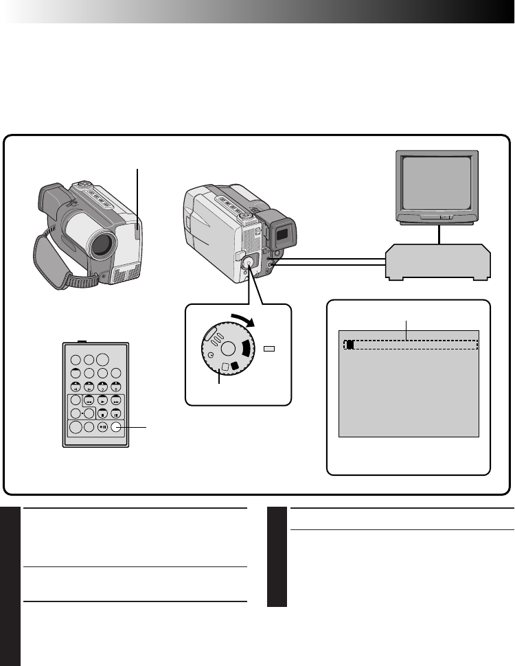
66 EN
3
PLAY BACK DUBBED SCENE
•If any images from the scene prior to the
transition you chose for your Edit-In point
were recorded, that means your VCR moves
quickly from Record-Pause to Record mode.
•If the scene you tried to dub starts in
progress, the VCR is slow to start recording.
For More Accurate Editing
Some VCRs make the transition from Record-Standby to Record mode faster than others. Even if you begin
editing for the camcorder and the VCR at exactly the same time, you may lose scenes you wanted, or find
that you’ve recorded scenes you didn’t want. For a cleanly edited tape, confirm and adjust the timing of the
camcorder against your VCR.
Diagnosing VCR’s against Camcorder Timing
1
PREPARE FOR R.A. EDIT
Play back the tape in the camcorder, then point
the remote control at the camcorder’s remote
sensor and press R.A. EDIT ON/OFF.
•“Random Assemble Editing Menu” appears
on the TV screen.
2
CHOOSE A SCENE
Perform Random Assemble Editing on Program
1 only. In order to check VCR and camcorder
timing, select the beginning of a scene
transition as your Edit-In point.
TW
1 –– –– : ––
~
2
~
3
~
4
~
5
~
6
~
7
~
8
~
TIME CODE
IN OUT MODE
–– : ––
00 : 00
TOTAL
A
M
5S
OFF
P
L
A
Y
Random Assemble Editing Menu
VCR
(Recording deck)
R.A.EDIT ON/OFF
Program 1
RM-V711U (provided)
Remote sensor
Power Dial
EDITING
(Cont.)
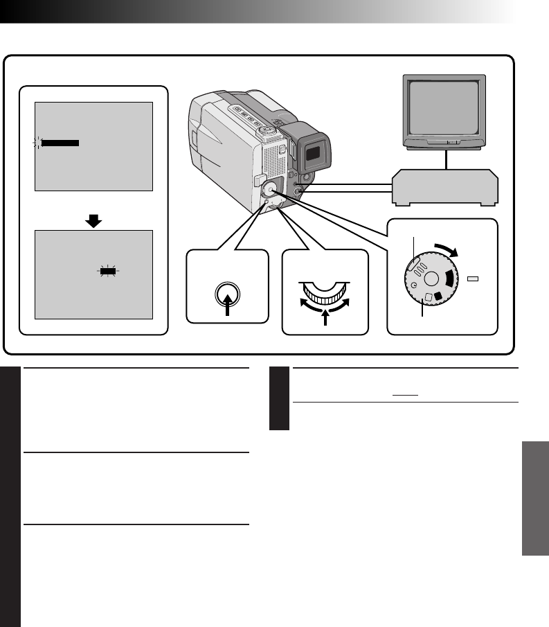
EN 67
7
CLOSE MENU
Press the Select Dial twice.
•Now perform Random Assemble Editing
beginning with step 2 on page 63.
NOTES:
●
Before performing actual Random Assemble
Editing, do a few Random Assemble Editing trial
runs to check whether the value you have input is
appropriate or not, and make adjustments
accordingly.
●
Depending on the recorder, there may be
situations where the timing difference cannot be
fully corrected.
4
ACCESS PLAYBACK MENU
Point the remote control at the camcorder’s
remote sensor and press R.A. EDIT ON/OFF to
make the Random Assemble Editing menu
disappear, then press MENU. The Playback
Menu appears on the TV screen.
5
SELECT FUNCTION
Move the pointer and highlight bar to
“SYNCHRO” by rotating the Select Dial, then
press it. The value for “SYNCHRO” is high-
lighted.
6
INPUT CORRECTION DATA
Based on the diagnostics performed (Z pg. 66),
you can now increase the VCR’s speed by
rotating the Select Dial to the right. You can
also slow down the VCR’s speed by rotating the
Select Dial to the left. The adjustment range is
from –1.3 to +1.3 seconds, in 0.1-second
increments.
SOUND1
0 . 0
ON
OFF
FULL SOUND48kHz MODE
32kHz MODE
DISPLAY
TIMECODE
SYNCHRO
END
4
SOUND1
0 . 0
ON
OFF
FULL SOUND48kHz MODE
32kHz MODE
DISPLAY
TIMECODE
SYNCHRO
END
4
A
M
5S
OFF
P
L
A
Y
Adjustment of VCR‘s against Camcorder Timing
VCR
(Recording deck)
Playback Menu
Power Dial
Lock button
Select DialMENU button
Display
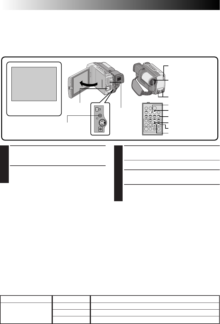
68 EN
Audio Dubbing
The audio track can be customized only when recorded on the 32 kHz mode (Z pg. 35).
NOTES:
●
Audio Dubbing is not possible on a tape recorded at 48 kHz, on a tape recorded in the LP mode or on a
blank portion of a tape.
●
To perform Audio Dubbing while watching in the television, make connections (
Z
pg. 56, 57).
TW
6e
1
FIND EDIT-IN POINT
Play back the tape to locate the point where
editing will start, then press PAUSE.
2
ENGAGE AUDIO DUB STANDBY
While holding A. DUB on the remote control,
press PAUSE. “6e” appears.
RECORDING SOUND DISPLAY OUTPUT SOUND
32 kHz FULL SOUND Original and new tracks are combined and output in stereo.
SOUND 2 New track is output on both “L” and “R” channels in stereo.
SOUND 1 Original track is output on both “L” and “R” channels in stereo.
Speaker
3
BEGIN DUBBING
Press PLAY, then begin “narrating”.
•Speak into the microphone.
4
PAUSE DURING DUBBING
Press PAUSE.
5
STOP DUBBING
Press STOP.
Audio Dub Standby
Stereo microphone
Power Dial
Remote sensor
RM-V711U
(provided)
PLAY
STOP
PAUSE
A.DUB
AUDIO MONITOR
DISPLAY
External microphone
input connector
(Located beneath
the cover.)
NOTES:
●
Audio dubbing is possible using an optional microphone connected to the external microphone input
connector (MIC).
●
While an optional microphone is connected, the built-in microphone is disabled.
●
When editing onto a tape that was recorded at 32 kHz, the old and new soundtracks are recorded separately.
●
To select the desired sound for playback, press AUDIO MONITOR on the remote control.
●
If you dub onto a blank space on the tape, the sound may be disrupted. Make sure you only edit recorded
areas.
●
If feedback or howling occurs during TV Playback, move the camcorder’s microphone away from the TV,
or turn down the TV’s volume.
●
Sound is not heard from the speaker during Audio Dubbing. To hear sound, connect optional headphones
to the AV OUT (headphones) connector.
●
If you change from 32 kHz to 48 kHz in mid-recording and then use the tape for Audio Dubbing, it is not
effective from the point where 48 kHz recording began.
●
During Audio Dubbing, when the tape moves to scenes recorded in the LP mode, scenes recorded at 48 kHz
or a blank portion, Audio Dubbing stops and “ERROR! REFER MANUAL” appears.
AV OUT
(headphones)
connector
EDITING
(Cont.)
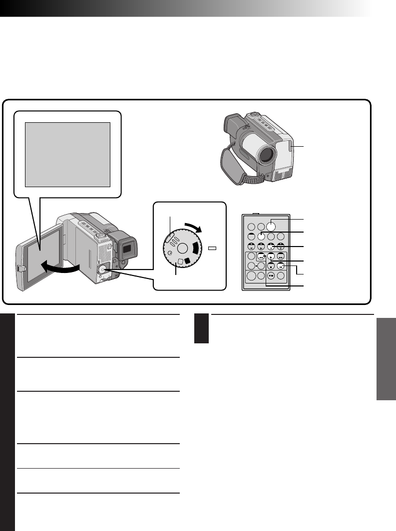
EN 69
TW
TC 12 : 34
6w
A
M
5S
OFF
P
L
A
Y
Insert Editing
You can record a new scene into a previously recorded tape, replacing a section of the original recording
with minimal picture distortion at the in- and out-points. The original audio remains unchanged.
NOTES:
●
Insert Editing is not possible on a tape recorded in the LP mode or on a blank portion of a tape.
●
To perform Insert Editing while watching in the television, make connections (
Z
pg. 56, 57)
1
FIND EDIT OUT POINT
Playback the tape to locate the point where
you want to stop editing. Confirm the time
code at this point (Z pg. 55).
2
FIND EDIT IN POINT
Press REW until the point is located, then press
PAUSE.
3
PREPARE FOR INSERT EDITING
Press and hold INSERT on the remote control,
then press PAUSE. “6w” and the Time Code
(min.:sec.) appear and the camcorder enters
Insert-Pause mode.
4
START RECORDING
Press START/STOP to begin editing.
•Confirm the insert at the time code you
checked in step 1.
5
PAUSE DURING EDITING
Press START/STOP. The camcorder re-enters
Insert Pause mode. Press again to resume
editing.
Power Dial
START/STOP
DISPLAY
INSERT
PLAY
PAUSE
REW(IND)
6
STOP EDITING
Press STOP while the camcorder is in the
Insert-Pause mode.
NOTES:
●
P.AE/Effects (
Z
pg. 42) can be used to spice up
the scenes being edited during Insert Editing.
●
To display the Time Code during Insert Editing,
(
Z
pg. 54).
●
When performing Insert Editing, the tape’s Video
Area and Sub-Code Area (
Z
pg. 6) are rewritten,
so the date and time information changes.
●
If you perform Insert Editing onto a blank space
on the tape, the audio and video may be
disrupted. Make sure you only edit recorded
areas.
●
During Insert Editing, when the tape moves to
scenes recorded in the LP mode or a blank
portion, Insert Edting stops and “ERROR! REFER
MANUAL” appears.
Remote sensor
RM-V711U (provided)
Lock button
70 EN
SYMPTOM POSSIBLE CAUSES CORRECTIVE ACTION
1.
No power is supplied.
2.
“SET DATE/TIME!”
appears.
3.
Recording cannot be
performed.
4.
There is no playback
picture.
5.
Some functions are not
available using the MENU
button.
6.
Some functions are not
available using the Select
Dial.
7.
The focus does not adjust
automatically.
8.
The cassette won’t load
properly.
9.
Play, Rewind and
Fast-Forward functions
don’t work.
1.
•The power is not connected
properly.
•The battery is dead.
•The LCD monitor is not
open fully or the viewfinder
is not pulled out when
recording.
2.
•The built-in rechargeable
clock lithum battery is
discharged and the
previously set date/time is
erased.
3.
•The tape’s record safety tab
is set to “SAVE”.
•The Power Dial is set to
“PLAY”.
•“TAPE END” appears.
•The cassette's cover is open.
4.
•The camcorder is not getting
power, or some other
malfunction exists.
5.
•The Power Dial is set to
“
A
”.
6.
•The Power Dial is set to
“
A
”, “5S” and “ ”.
7.
•Focus is set to “MANUAL”.
•The recording was done in a
dark place, or the contrast
was low.
•The lens is dirty or covered
with condensation.
8.
•The cassette is in the wrong
position.
•The battery’s charge is low.
9.
•The Power Dial is not set to
“PLAY”.
1.
•Connect the AC Adapter
securely (Z pg. 10).
•Replace the dead battery
with a fully charged one
(Z pg. 9).
•Open the LCD monitor
fully or pull out the
viewfinder. The LCD
monitor turns on/off when
it is opened/closed at
approx. 90° while the
Power Dial is set to any
position except “OFF” if the
viewfinder is not fully
pulled out.
2.
•Connect the camcorder to
an AC outlet using the AC
Power Adapter/Charger etc.
for over 24 hours to charge
the clock lithum battery
(Z pg. 11).
3.
•Set the tape’s record safety
tab to “REC” (Z pg. 12).
•Set the Power Dial to “
A
”,
“
M
”, “5S” or “ ”
(Z pg. 17).
•Replace with new cassette
(Z pg. 12).
•Close the cassette's cover.
4.
•Turn the camcorder’s power
off and on again (Z pg. 19).
5.
•Set the Power Dial to any
position except “
A
”
(Z pg. 17).
6.
•Set the Power Dial to any
position except “
A
”, “5S”
and “ ” (Z pg. 17).
7.
•Set Focus to “AUTO”
(Z pg. 45).
•Clean the lens and check
the focus again (Z pg. 75).
8.
•Set it in the right position
(Z pg. 12).
•Install a fully charged
battery (Z pg. 8).
9.
•Set the Power Dial to
“PLAY” (Z pg. 50).
If, after following the steps in the chart below, the problem still exists, please consult your nearest JVC
dealer.
TROUBLESHOOTING

EN 71
SYMPTOM POSSIBLE CAUSES CORRECTIVE ACTION
10.
The tape is moving, but
there’s no picture.
11.
In the 5-Second mode,
recording ends before
5 seconds have elapsed.
12.
Pro Snapshot mode
cannot be used.
13.
Digital Zoom doesn’t
work.
14.
P.AE/Effects and Fade/
Wipe Effects don’t work.
15.
The Black & White Fader
doesn’t work.
16.
The Dissolve function
doesn’t work.
17.
Scene transition does not
go as expected.
10.
•Your TV has AV input
terminals, but is not set to
its VIDEO mode.
•The cassette’s cover is open.
11.
•The 5-Second mode in the
System Menu is set to
“ANIM.”.
12.
•The Squeeze mode is
selected.
13.
•10X optical zoom is selected.
•The Video Echo effect is
activated.
•Picture Wipe or Dissolve
are being used in a scene
transition.
•5-Second recording was
done with the Power Dial
set to “5S”, and with “5SD”
selected in the System Menu.
•Pro Snapshot was attempted
during Digital Zoom.
14.
•The Power Dial is set to
“
A
”.
•The Power Dial is set to
“5S”.
15.
•The Sepia or Monotone
effects are activated.
16.
•P.AE/Effects Sepia,
Monotone or Slow are
activated.
•The Squeeze mode is
selected.
•The previously selected
P.AE/Effect was changed
after the last selected scene
for editing was registered.
17.
•When using “Picture Wipe/
Dissolve” (Z pg. 38) or
“Dissolves during 5 second
mode recording” (Z pg. 26),
there is a delay of a fraction
of a second between the
previous record stop-point
and the Dissolve start-point.
This is normal, but this slight
delay becomes especially
noticeable when shooting
fast-moving subject or
during rapid panning.
10.
•Set the TV to the mode or
channel appropriate for
video playback (Z pg. 56,
57).
•Close the cassette's cover
(Z pg. 12).
11.
•Select “5S” or “5SD” in the
System Menu (Z pg. 35).
12.
•Disengage the Squeeze
mode (Z pg. 32).
13.
•Turn off the Video Echo
effect (Z pg. 43).
•Wait until the Picture Wipe
or Dissolve effects are
completed (Z pg. 38).
•Change the setting of either
the System Menu or the
Power Dial (Z pg. 34).
•Do not attempt to take a
Pro Snapshot when
performing Digital Zoom
(Z pg. 26).
14.
•Set the Power Dial to “
M
”
(Z pg. 17).
•Change the setting of the
Power Dial.
15.
•Turn off Sepia and
Monotone (Z pg. 42).
16.
•Turn off Sepia and
Monotone before adding
Dissolve to a scene
transition (Z pg. 42).
•Make sure that the Squeeze
mode in the Recording
Menu is set to “OFF”
(Z pg. 32).
•Make sure you have
selected the P.AE/Effects
you want before starting
editing (Z pg. 42).
17.
————
CONTINUED ON NEXT PAGE

72 EN
SYMPTOM POSSIBLE CAUSES CORRECTIVE ACTION
18.
•The last selected editing
scene is ending.
•At the end of the last
selected scene for editing,
the Power Dial was set to
“OFF”.
•The power is off.
19.
•The Slow Shutter effect is
activated.
•The Squeeze or Cinema
mode is selected in the
Recording Menu.
20.
•When shooting in the dark,
the unit becomes highly
sensitive to light and the
image takes on an effect
similar to Slow Shutter.
21.
•The Picture Wipe or
Dissolve functions are in use.
•The Squeeze mode is
selected in the Recording
Menu.
•A Fade-In or Fade-Out is in
progress (White Fader, Black
Fader or Black & White
Fader).
22.
•The Picture Wipe or
Dissolve functions are in
use.
23.
•The Sepia or Monotone
effects are activated.
24.
•This is a result of
exceedingly high contrast,
and is not a malfunction.
25.
•This is not a malfunction.
18.
•Select Picture Wipe or
Dissolve before beginning
recording. The effects are
then automatically
activated (Z pg. 38).
•Do not turn off the
camcorder’s power after
setting Edit-In and Edit-Out
points, as they will all be
erased (Z pg. 38).
•The camcorder
automatically shuts off
after 5 minutes have
elapsed in the Record-
Standby mode. Make
sure you continue
operations within
5 minutes after engaging
Record-Standby mode
(Z pg. 38).
19.
•Make sure the Squeeze
mode, Cinema mode, or
Slow Shutter effect is not
activated when preparing
to use the Picture Wipe
function
(Z pg. 32, 43).
20.
•If you want the lighting to
look more natural, set
GAIN UP to “AGC” or
“OFF” in the Recording
Menu (Z pg. 32).
21.
•Make sure the Squeeze
mode is set to “OFF”
(Z pg. 32).
•Do not try to use the Video
Echo effect during a
Fade-In or Fade-Out
(Z pg. 36).
22.
•Do not try to use the
Classic Film or Strobe
effects during a scene
transition (Z pg. 43).
23.
•Turn off Sepia or Monotone
before setting White
Balance (Z pg. 42).
24.
————
25.
————
18.
The Picture Wipe and
Dissolve functions don’t
work.
19.
The Picture Wipe function
doesn’t work.
20.
Even when Slow Shutter
isn't selected, the image
looks like it is activated.
21.
The Video Echo effect
doesn’t work.
22.
There is no strobe when
the Classic Film and
Strobe effects are
activated.
23.
White Balance cannot be
activated.
24.
When shooting a subject
illuminated by bright
light, vertical lines appear.
25.
When the screen is under
direct sunlight during
shooting, the screen becomes
red or black for an instant.
TROUBLESHOOTING
(Cont.)

EN 73
SYMPTOM POSSIBLE CAUSES CORRECTIVE ACTION
26.
•If Audio Dubbing or Insert
Editing have been performed
repeatedly on the same
portion of the tape,
disturbance to the sound
and picture may result.
27.
•“DISPLAY” is set to “OFF” in
the Date/Time Menu.
•Interface shooting is
performed.
28.
•“ON SCREEN” is set to
“OFF” in the Date/Time
Menu.
29.
•You have made the
indicators disappear.
30.
•
In places subject to low
temperature, images become
dark due to the characteristics
of the LCD monitor. When
this happens, the displayed
colours differ from those that
are actually recorded. This is
not a defect of the camcorder.
•
When the LCD monitor's
fluorescent light reaches the
end of its service life, images
on the LCD monitor become
dark. Consult your nearest JVC
dealer.
31.
•The light used to illuminate
the LCD monitor causes it to
become hot.
32.
•This may occur when the
surface or the edge of the
LCD monitor is pressed.
33.
•The speaker volume is too
great.
34.
————
26.
•Use a new, or infrequently
used, tape for Audio
Dubbing and Insert Editing
(Z pg. 68, 69).
27.
•Set “DISPLAY” to “ON” in
the Date/Time Menu
(Zpg. 11).
•During interface shooting,
the date/time does not
appear (Z pg. 23).
•Press the ON/OFF button
for longer than 1 second to
make the indicators appear
(Z pg. 22).
28.
•Set “ON SCREEN” to “ON”
in the Date/Time Menu
(Z pg. 25).
•Press the ON/OFF button
for longer than 1 second to
make the indicators appear
(Z pg. 22).
29.
•Press the ON/OFF button
for longer than 1 second to
make the indicators appear
(Z pg. 22).
30.
•Adjust the brightness and
angle of the LCD monitor
(Z pg. 22, 23).
31.
•Close the LCD monitor to
turn it off or set the Power
Dial to “OFF”, and let the
unit cool down (Z pg. 19).
32.
————
33.
•Turn the speaker volume
down (Z pg. 51).
34.
•Wipe them gently with soft
cloth. Wiping strongly can
cause damage.
26.
There are disturbances in
audio and video.
27.
During recording, the
date/time does not
appear.
28.
The indicators and
messages do not appear
on screen.
29.
The indicators do not
appear on the LCD
monitor or in the
viewfinder.
30.
Images on the LCD
monitor appear dark or
whitish.
31.
The rear of the LCD
monitor is hot.
32.
The indicators and the
image colour on the LCD
monitor are not clear.
33.
Images on the LCD
monitor are jittery.
34.
The LCD monitor and the
lens have become dirty
(ex. fingerprints).
CONTINUED ON NEXT PAGE

74 EN
SYMPTOM POSSIBLE CAUSES CORRECTIVE ACTION
35.
•Certain FADE/WIPE, P.AE/
Effects, DIS and other
functions that cannot be
used together are selected at
the same time.
36.
•The LCD monitor or the
viewfinder is made with
high-precision technology.
However, black spots or
bright spots of light (red,
green or blue) may appear
constantly on the LCD
monitor or the viewfinder.
These spots are not recorded
on the tape. This is not due
to any defect of the unit.
(Effective dots: more than
99.99 %)
37.
•During playback of the
unrecorded portion, High-
speed Search and still
playback, LCD monitor
indications appear distorted.
This is not a defect.
38.
————
39.
•A malfunction of some kind
has occurred. In this case
the camcorder’s functions
become unusable.
40.
•The temperature of the
battery is extremely high/low.
•Charging is difficult in
places subject to extremely
high/low temperatures.
41.
•This occurs when recording in
the LP mode is not available.
After the indicator blinks, the
recording mode switches to
“SP” and recording goes on.
42.
•The viewfinder is pulled out.
•The LCD monitor's
brightness setting is too
dark.
43.
•This is not a malfunction.
35.
•Re-read the sections
covering FADE/WIPE, P.AE/
Effects and DIS
(Z pgs. 33, 36 – 43).
36.
————
37.
————
38.
•
Check the section of the
manual that explains LCD
monitor/viewfinder
indications (
Z
pgs. 79 – 81).
39.
•
Remove the power supply
(battery pack, etc.) and press
RESET button, and wait a few
minutes for the indication to
clear. When it does, you can
resume using the camcorder.
If the indication remains
even though you repeat the
above two or three times,
please consult your nearest
JVC dealer.
40.
•To protect the battery, it is
recommended to charge it
in places with a tempera-
ture of 10°C to 30°C
(Z pg. 9).
41.
————
42.
• Push the viewfinder back in.
•Adjust the brightness of the
LCD monitor (Z pg. 22).
• If the monitor is tilted
upward 180 degrees, open
the monitor fully (Z pg. 23).
43.
• By recording with Digital
Image Stabilizer set to “ON”
(Z pg. 33) this can be
avoided.
35.
The LCD monitor
indications blink.
36.
Coloured bright spots
appear all over the LCD
monitor or the viewfinder.
37.
The LCD monitor
indications are distorted.
38.
An unusual mark appears
in the LCD monitor or the
viewfinder.
39.
An error indication
(E01 — E07) appears in
the LCD monitor or the
viewfinder.
40.
The charge indicator on
the AC Power Adapter/
Charger does not light.
41.
The recording mode
indicator “LP” blinks on
the LCD monitor or the
viewfinder.
42.
Picture does not appear
on the LCD monitor.
43.
When the image is
printed from the printer, a
black bar appears at the
bottom of the screen.
TROUBLESHOOTING
(Cont.)
EN 75
1
REMOVE POWER SUPPLY
Remove the battery pack or disconnect the AC
Power Adapter/Charger (Z pg. 8, 9).
2
CLEAN EXTERIOR
Wipe gently with a soft cloth.
•Put cloth in diluted mild soap and wring it
well to wipe off heavy dirt. Then wipe again
with a dry cloth.
3
CLEAN LENS
Blow it with a blower brush, then wipe gently
with lens cleaning paper.
4
PULL OUT VIEWFINDER
Pull out the viewfinder fully.
5
CLEAN VIEWFINDER
Use a small screwdriver to lift the viewfinder
eject knob up and clean the viewfinder with a
lens blower or a soft cloth.
AFTER USE
6
PUSH VIEWFINDER BACK IN
Return the viewfinder eject knob to its original
position and push the viewfinder back in.
7
OPEN LCD MONITOR
Open the LCD monitor fully.
8
CLEAN LCD MONITOR
With soft cloth, gently wipe the LCD monitor
in a semicircular pattern. Avoid using too
much pressure as this will smear the monitor
screen, making it much more difficult to clean.
9
CLOSE LCD MONITOR
NOTES:
●
Avoid using strong cleaning agents such as
benzine or alcohol. This may damage the unit's
body or cause malfunction.
●
When using a cleaner or chemically treated cloth
refer to the cautions of each product.
Cleaning The Camcorder
Battery cover
LCD monitor Viewfinder eject knob
Battery pack Open switch (BATTERY)
Hook
76 EN
S
N
A
P
S
H
O
T
V
I
D
E
O
!
3
1
25
6
7
8 9
&
*
(
r
) q w e
0
@
#
$
^
%
4
CONTROLS, INDICATIONS AND CONNECTORS
Connector cover
Pull this out to open.

EN 77
%Progressive Dial (PROGRESSIVE)
(Z pg. 28, 44)
Turn for Progressive Video Recording or Pro
Snapshot Recording.
^Progressive Button (Z pg. 28, 44)
When this button is pressed, the camcorder starts
Progressive Mode Recording (high resolution).
When pressed during playback, a playback
snapshot is taken.
&OPEN/EJECT switch (Z pg. 12)
Slide the switch down when loading/unloading a
tape.
*Speaker (Z pg. 50)
During playback, the sound can be heard.
(PUSH-OPEN Button (Z pg. 12)
Press to open the LCD monitor.
)Power dial (Z pg. 18)
Turning the camcorder on/off, recording or
playback is possible.
qMENU button (Z pg. 31)
Press this button to make the Menu appear.
ON/OFF button (Z pg. 22)
Press and hold this button for more than approx.
1 second to make the indications appear on the
LCD monitor or the viewfinder.
wFunction Navigator Dial (Select Dial)
(Z pg. 22, 31)
Adjusts the brightness of the LCD monitor or
selects the Menu etc. Referred to in this manual
as “Select Dial”.
eSTART/STOP button (Z pg. 18)
Starts recording or stops recording to make the
camcorder enter the record-standby mode.
rViewfinder (Z pg. 15)
Pull out when recording.
1Zoom switch or volume switch (VOL.)
(Z pg. 24, 50)
Adjusts zoom during recording or the sound
volume during playback.
2Grip strap (Z pg. 14)
3Tally lamp
Lights during recording.
4Remote sensor (Z pg. 52)
Receives the signal from the remote control.
When using the remote control, point it at the
remote sensor.
5Lens cover
Opens when the viewfinder is pulled out or the
LCD monitor is opened fully.
6Stereo microphone (Z pg. 68)
For use when recording or audio dubbing.
7External microphone input connector
(MIC) (Stereo) (Z pg. 68)
An optional microphone can be connected.
8JLIP (Joint Level Interface Protocol)
(DIGITAL STILL) output connector
(Z pg. 58)
Outputs the digital still image to a personal
computer.
9EDIT jack
Using an editing cable, connect to the remote
control or VCR (Z pg. 63)
0RESET button (Z pg. 74)
When a malfunction occurs, press this button
after removing the power supply (battery etc.).
Pressing this button also resets the date/time or
various settings.
!Stop button (5) (Z pg. 50)
Stops playback of the tape.
@Play/Pause button (6/
4
) (Z pg. 50)
Plays back or stops the tape temporarily.
#Fast-Forward button (
3
) (Z pg. 50)
Fast-Forwards the tape.
$Rewind button (
2
) (Z pg. 50)
Rewinds the tape.
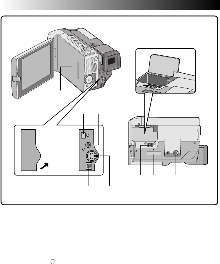
78 EN
t
y
po
REW
Q
u i
tLCD monitor (Z pg. 22)
The image appears during recording or play-
back.
yCassette cover (Z pg. 12)
uDV OUT connector (Z pg. 58, 59, 61)
Connect to a video unit equipped with a DV
connector.
iVideo/audio output connector or head-
phones connector ( /AV-OUT)
(Z pg. 56, 57, 68)
The provided VIDEO/AUDIO cable (ø3.5) can
be connected to a television etc. Using optional
headphones, you can listen to the sound.
However, headphones equipped with volume
control cannot be used.
oDC IN jack (Z pg. 10)
The DC cord of an AC Power Adapter can be
connected.
pS OUT (S2 OUT) connector
(Z pg. 56, 57, 63)
Connect to a video unit equipped with an S-
Video connector.
QBattery cover (Z pg. 9)
Open the battery cover to insert the battery.
WBattery cover open switch (BATTERY)
(Z pg. 9)
Slide in the direction of the arrow to open the
battery cover.
EPower Pack (MULTI) connector
(Z pg. 10)
Attach to the Power Pack (optional).
RTripod mounting socket (Z pg. 14)
Bottom of the
camcorder
Connector cover
Pull this out to
open.
CONTROLS, INDICATIONS AND CONNECTORS
(Cont.)
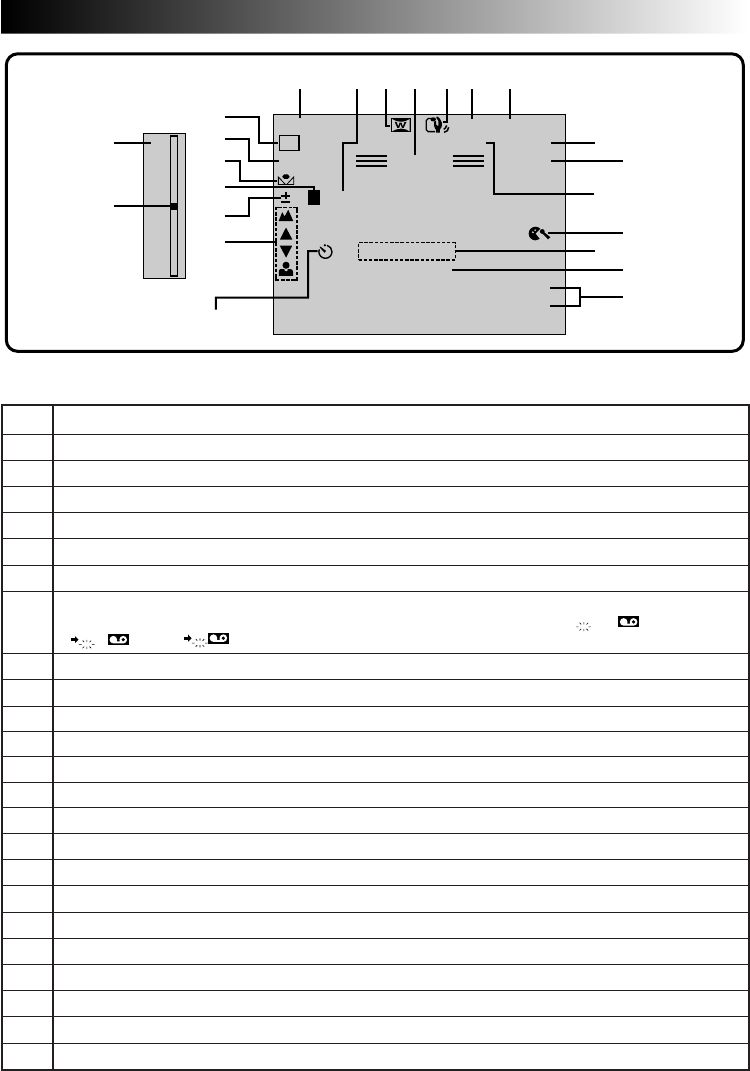
EN 79
LP 35 min
PAUSE
MODE
32kHz 25 . 12 . 98
17 : 46
5S
SOUND
444
RECPS
0 L PHOTO
W
H
1/250
D
T
W
1*2*3 5 6*7*4*
8*
0*
9
@*#
!
^
*
&
(
)
q
%*
e
w
$*
MANUAL
No. FUNCTION
1*Displays the operation mode position. (Z pg. 17)
2*Appears when taking a Pro Snapshot. (Z pg. 28)
3Appears when in the Squeeze or Cinema mode. (Z pg. 32)
4*Appears when in the Record-Standby mode. (Z pg. 18)
5Appears when Digital Image Stabilizer is engaged. (Z pg. 33)
6*Displays the recording mode (SP or LP). (Z pg. 13)
7*Displays the tape remaining time. During Interface Shooting (Z pg. 23), when the tape
remaining time reaches 2 minutes, this indication is shown as follows;
– – –
2 min.
– – 1 min. – 0 min.
8*Appears during recording. (Z pg. 18)
9Appears while the tape is running. (Z pg. 18)
0*Appears when Progressive Video Recording is selected. (Z pg. 44)
!Appears when the wind cut mode is engaged to cut down on noise created by wind. (Z pg. 35)
@*Displays the 5 second mode recording or animation recording mode. (Z pg. 26)
#Displays the sound mode for approx. 5 seconds after turning on the camcorder. (Z pg. 35)
$*Displays the date/time. (Z pg. 25)
%*Appears during self-timer recording. (Z pg. 27)
^Appears when the focus is adjusted manually. (Z pg. 45)
&Appears when the exposure is adjusted. (Z pg. 46)
*Appears when the iris is locked. (Z pg. 47)
(Appears when the white balance is adjusted. (Z pg. 48)
)Displays the selected P.AE/Effect. (Z pg. 42)
qDisplays the selected Fade/Wipe effect. (Z pg. 36)
wAppears when Digital Zoom is activated. (Z pg. 33)
eAppears during zooming. (Z pg. 25)
LCD Monitor/Viewfinder Indications During Recording
*:Pressing ON/OFF for longer than 1 second lets you remove indications marked with * from the screen.
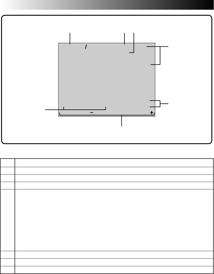
80 EN
SOUND1
32kHz LP
PS
25 . 12 . 98
17 : 46
– – – – – – – – – –
TC 01 : 28 : 15
6
4
6w
VOLUME
1 2 3
4
5
7
6
LCD Monitor/Viewfinder Indications During Playback
No. FUNCTION
1Displays the sound mode. (Z pg. 55)
2Displays the recording mode of the tape being played back.
3Appears during playback of scenes recorded in the Progressive Mode.
4Appears while a tape is running.
4
: Playback
3
: Fast-Forward/High-speed search
2
: Rewind/High-speed search
6
4
: Forward slow-motion
6
1
: Reverse slow-motion
6: Pause
w: Insert
e: Audio Dubbing
5Displays the date/time. (Z pg. 55)
6Displays the brightness of the LCD monitor or the speaker volume. (Z pg. 22, 50)
7Displays the time code. (Z pg. 55)
CONTROLS, INDICATIONS AND CONNECTORS
(Cont.)
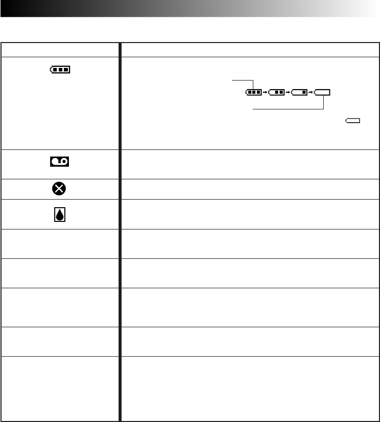
EN 81
ERROR!
REFER MANUAL
INDICATIONS FUNCTION
Displays the battery remaining power.
Remaining power level: high
Remaining power level: exhausted
As the battery power comes close to nil, the battery indicator
blinks. When the battery power is exhausted, power turns off
automatically.
Appears when no tape is loaded, or when the erase
protection tab is set to “SAVE”. (Z pg. 12)
Appears if dirt is detected on the heads during recording.(Z pg. 83)
Appears if condensation occurs. When this indication is displayed,
the camcorder turns off automatically.
Appears for 10 seconds after power is turned on if there's no tape
loaded.
Appears when the tape ends during recording
or playback. (Z pg. 22)
●Appears when the date/time is not set. (Z pg. 11)
●Appears when the built-in rechargeable battery is
discharged and the previously set date/time is erased. (Z pg. 11)
●Appears when Audio Dubbing is unavailable. (Z pg. 68)
●Appears when Insert Editing is unavailable. (Z pg. 69)
The error indications (E01 — E07) show what type of malfunction has
occured. When an error indication appears, the camcorder turns off
automatically. Press the reset button after removing the power supply
(battery, etc.), and wait a few minutes for the indication to clear.
When it does, you can resume using the camcorder. If the indication
remains, consult your nearest JVC dealer. (Z pg. 74)
Warning Indications
TAPE!
TAPE END
SET DATE/TIME!
E01 — E07

82 EN
Battery Packs
The supplied battery pack is a
lithium-ion battery. Before
using the supplied battery pack
or an optional battery pack, be
sure to read the following
cautions:
1. To avoid hazard . . .
.... do not burn.
.... do not short-circuit the terminals.
.... do not modify or disassemble.
.... do not expose the battery to temperatures
exceeding 60°C, as this may cause the
battery to overheat, explode or catch fire.
.... use only specified chargers.
2. To prevent damage and prolong service life . . .
.... do not subject to unnecessary shock.
.... charge in an environment where tempera-
tures are within the tolerances shown in the
chart below. This is a chemical reaction type
battery—cooler temperatures impede
chemical reaction, while warmer tempera-
tures can prevent complete charging.
.... store in a cool, dry place. Extended exposure
to high temperatures will increase natural
discharge and shorten service life.
.... fully charge and then fully discharge the
battery once a year when storing the battery
pack over a long period time.
.... remove from charger or powered unit when
not in use, as some machines use current
even when switched off.
NOTES:
●
It is normal for the battery pack to be warm after
charging, or after use.
Temperature Range Specifications
Charging ................................ 10°C to 35°C
Operation .............................. 0°C to 40°C
Storage .................................. –10°C to 30°C
●
Recharging time is based on room temperature of
20°C.
●
The lower the temperature, the longer recharging
takes.
How To Handle A CD-ROM
•Take care not to soil or scratch the mirror surface
(opposite to the printed surface). Do not write
anything or put a sticker on either the front or
back surface. If the CD-ROM gets dirty, gently
wipe it with a soft cloth outward from the centre
hole using a circular motion.
•Do not use conventional disc cleaners or cleaning
spray.
•Do not bend the CD-ROM or touch its mirror
surface.
•Do not store your CD-ROM in a dusty, hot or
humid environment. Keep it away from direct
sunlilght.
CAUTIONS
Terminals
Cassettes
To properly use and store your cassettes, be sure to
read the following cautions:
1. During use . . .
.... make sure the cassette bears the Mini DV
mark.
.... be aware that recording onto prerecorded
tapes automatically erases the previously
recorded video and audio signals.
.... make sure the cassette is positioned properly
when inserting.
.... do not load and unload the cassette
repeatedly without allowing the tape to run
at all. This slackens the tape and can result in
damage.
.... do not open the front tape cover. This
exposes the tape to fingerprints and dust.
2. Store cassettes . . .
.... away from heaters or other heat sources.
.... out of direct sunlight.
.... where they won’t be subject to unnecessary
shock or vibration.
.... where they won’t be exposed to strong
magnetic fields (such as those generated by
motors, transformers or magnets).
.... vertically, in their original cases.
Main Unit
1. For safety, DO NOT . . .
.... open the camcorder’s chassis.
.... disassemble or modify the unit.
.... short-circuit the terminals of the battery pack.
Keep it away from metallic objects when not
in use.
.... allow inflammables, water or metallic objects
to enter the unit.
.... remove the battery pack or disconnect the
power supply while the power is on.
.... leave the battery pack attached when the
camcorder is not in use.
2. Avoid using the unit . . .
.... in places subject to excessive humidity or
dust.
.... in places subject to soot or steam such as
near a cooking stove.
.... in places subject to excessive shock or
vibration.
.... near a television set.
.... near appliances generating strong magnetic
or electric fields (speakers, broadcasting
antennas, etc.).
.... in places subject to extremely high (over
40°C) or extremely low (under 0°C) tempera-
tures.
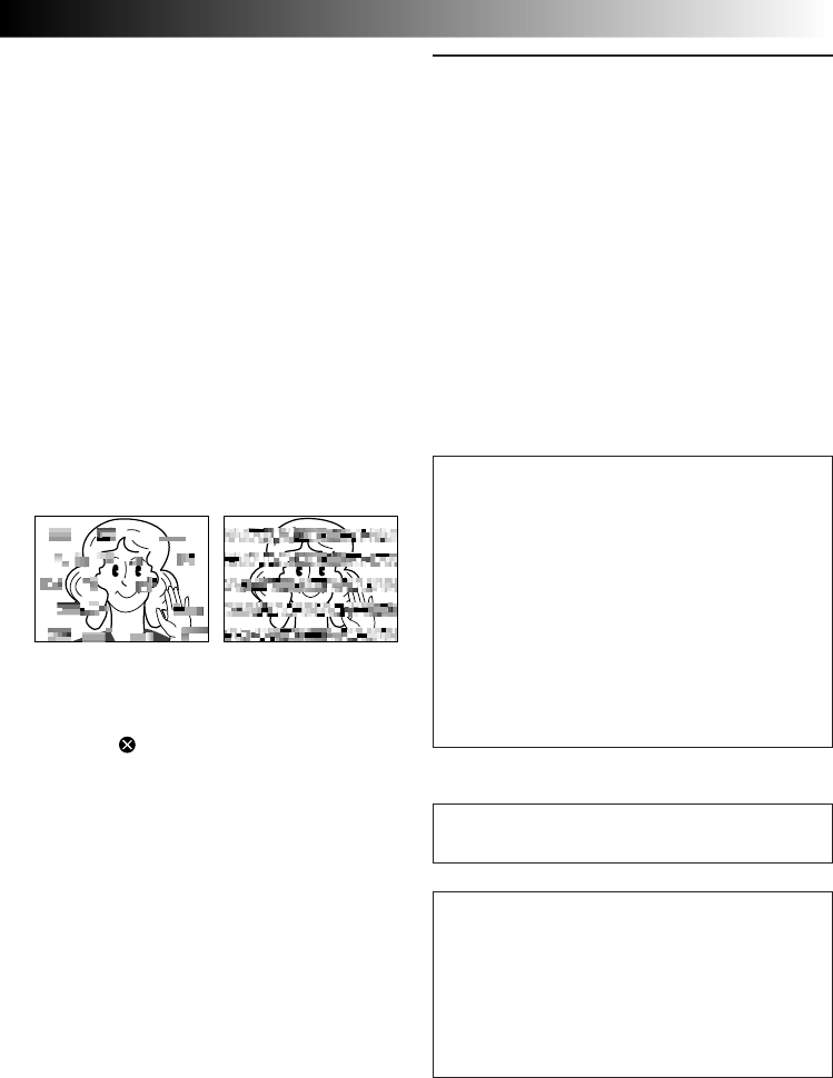
EN 83
3. DO NOT leave the unit . . .
.... in places of over 50°C (122°F).
.... in places where humidity is extremely low
(below 35%) or extremely high (above 80%).
.... in direct sunlight.
.... in a closed car in summer.
.... near a heater.
4. To protect the unit, DO NOT . . .
.... allow it to become wet.
.... drop the unit or strike it against hard objects.
.... subject it to shock or excessive vibration
during transportation.
.... keep the lens directed at extremely bright
objects for long periods.
.... expose the lens to direct sunlight.
.... carry it by holding the LCD monitor or the
viewfinder.
.... swing it excessively when using the hand
strap or the grip.
.... swing the soft camera case excessively when
the camcorder is inside it.
5. Dirty heads can cause the following problems:
•No picture and no sound during playback
(blueback).
•Blocks of noise appear during playback.
•During recording, the Head Clog Warning
indicator “ ” appears.
In such cases, use the optional Cleaning
Cassette. Insert it and play back. If the cassette is
used more than once consecutively, damage to
the video heads may result. After the camcorder
plays back for about 20 seconds, it stops
automatically. Also refer to the Cleaning
Cassette’s instructions.
If, after using the Cleaning Cassette, the
problems still exist, consult your nearest JVC
dealer.
Mechanical moving parts used to move the
video heads and video tape tend to become dirty
and worn out over time. In order to maintain a
clear picture at all times, periodic check-ups are
recommended after using the unit for about
1,000 hours. For periodic check-ups please
consult your nearest JVC dealer.
LCD monitor
1. To prevent damage to the LCD monitor,
DO NOT . . .
.... push it strongly or apply any shocks.
.... place the camcorder with the LCD monitor
on the bottom.
2. To prolong service life . . .
.... avoid rubbing it with coarse cloth.
3. Be aware of the following phenomena for LCD
monitor use.
These are not malfunctions . . .
•While using the camcorder, the surface around the
LCD monitor and/or the back of the LCD monitor
may heat up.
•If you leave power on for a long time, the surface
around the LCD monitor becomes hot.
About moisture condensation . . .
●You have observed that pouring a cold liquid
into a glass will cause drops of water to form
on the glass‘ outer surface. This same
phenomenon occurs on the head drum of a
camcorder when it is moved from a cool
place to a warm place, after heating a cold
room, under extremely humid conditions or
in a place directly subjected to the cool air
from an air conditioner.
●Moisture on the head drum can cause severe
damage to the video tape, and can lead to
internal damage to the camcorder itself.
Serious malfunctioning
If malfunctioning occurs, stop using the unit
immediately and consult your local JVC dealer.
The camcorder is a microcomputer-controlled
device. External noise and interference (from a
TV, a radio, etc.) might prevent it from function-
ing properly. In such cases, first disconnect its
power supply unit (battery pack, AC Power
Adapter/Battery Charger, etc.) and press the
RESET button and then re-connect it and
proceed as usual from the beginning.

84 EN
SPECIFICATIONS
CAMCORDER
General
Power : DC 6.3 V (using AC Adapter)
DC 7.2 V (using Battery)
Power consumption : 6.3 W (viewfinder on), 8.2 W (LCD monitor on)
Format : DV Format (SD mode)
Signal format : PAL Standard
Video signal recording format : Digital Component Recording
Cassette : MINI DV Cassette
Tape Speed : SP: 18.8 mm/s
LP: 12.5 mm/s
Maximum recording time : SP: 60 min.
LP: 90 min. (using DVM-60 cassette)
Pickup : 1/3" CCD (Progressive Scan CCD)
Lens : F1.2, f = 5 to 50 mm, 10:1 Power Zoom Lens
Filter diameter : ø58 mm (when using the optional lens adapter GL-V5842U)
LCD monitor : 4", 112,000 pixel TFT/LCD panel
Viewfinder : 0.55" colour LCD, 113,000 pixel
Operating temperature : 0 to 40°C
Operating humidity : 35 to 80%
Storage temperature : –20 to 50°C
Dimensions : 86 (W) x 86 (H) x 145 (D) mm
Weight : Approx. 670 g (without cassette and battery)
Approx. 780 g (incl. cassette and battery)
Video
Output : 1 Vp-p, 75 Ω unbalanced, analogue output
(via ø3.5 mm AV output jack)
S VIDEO output : Y: 1 Vp-p, 75 Ω, analogue output
C: 0.29 Vp-p, 75 Ω, analogue output
DV output : 4-pin, IEEE1394 compliant, digital output
Digital still output : ø3.5 mm, 4-pole, mini-head jack
(compatible with RC-5325 plug)
Audio
Output : –8 dBs, 1 kΩ analogue output
(via ø3.5 mm AV output jack)
Headphone output : Stereo
(via ø3.5 mm AV output jack)
External microphone input : –62 dBs, high impedance unbalanced with
ø3.5 mm (STEREO)
Speaker : Monaural
AC ADAPTER/CHARGER
Power : AC 110 to 240 V`, 50/60 Hz
Power consumption : 20 W
Output power : DC 7.2 V , 1.2 A (charge)
: DC 6.3 V , 1.8 A (VTR)
Operating temperature : 0°C to 40°C (when charging, 10°C to 35°C)
Dimensions : 94 mm (W) x 36 mm (H) x 122 mm (D)
Weight : Approx. 380 g (AA-V80EK)
Approx. 330 g (AA-V80EA)
Specifications shown are for SP mode unless otherwise indicated. E & O.E. Design and specifications
subject to change without notice.

EN 85
GLOSSARY OF TERMS
Iris
Works like the pupil of the human eye. In a well-lit environment, the human pupil contracts to keep too
much light from entering. In low lighting, the pupil dilates to allow more light in.
Colour temperature
A measurement in Kelvin degrees which indicates the colour contents of a light source; bluish light has a
higher colour temperature than reddish light. To reproduce white as white under different types of lighting,
the chrominance signal must be adjusted to match the light source’s colour temperature.
(See “White Balance”.)
AC Adapter
Used when charging the battery. Or, when connected directly to the camcorder, it can be used as a power
supply.
Auto focus
Focus can be set for automatic adjustment, for beginners who find the adjustment difficult.
On-screen display
Displays in the viewfinder or the LCD monitor can be shown on a connected TV.
Strobe
In the early days of movie making, 1-second strobes were uncommon, so movies didn’t have the smooth
movement they have today. This function gives movies the old-film flicker effect.
Record-Standby
Engage this mode by pressing START/STOP during Stop or Record modes. It means that the camcorder, or
your VCR, is paused and ready to record.
CCD (Charge coupled device)
Solid-state imaging device used in camcorders as the camera’s image pickup; analogous to the eye’s retina
except that picture information is output as electric signals.
Dew sensor
If condensation forms inside the unit due to a temperature change, the indicator appears in the viewfinder or
the LCD monitor, and the camcorder becomes unusable.
Digital zoom
10X Optical zoom image is taken and digitally processed to provide 40X or 100X magnified images.
Digital Image Stabilizer
When shooting while holding the camcorder in your hand, even if you think you’re perfectly still, there is
slight movement. This function compensates for that movement.
Fade
An effect used in scene transitions. Like movies or TV, the scene gradually goes black or white (fade out), or
comes in from a black or white screen (fade in).
White balance
A term that refers to the correctness of colour reproduction under various lighting. If the white balance is
correct, all other colours will be accurately reproduced.
Wipe
An effect used in scene transitions. A scene disappears as though it’s being wiped off the screen (wipe out),
or appears as though it’s wiped on (wipe in).

86 EN
INDEX
A
Animation ............................................... Z pg. 35
Audio Dubbing ....................................... Z pg. 68
Auto Focus .............................................. Z pg. 45
Auto Shut off ........................................... Z pg. 19
B
Battery .................................................... Z pg. 8
Battery Low ............................................. Z pg. 81
Beep/Tally ............................................... Z pg. 35
C
Charging ................................................. Z pg. 8
Cleaning The Camcorder ........................ Z pg. 75
Connections ........................ Z pg. 10, 56 – 59, 61
D
Date/Time Display ............................ Z pg. 25, 55
Date/Time Settings .................................. Z pg. 11
Digital Dubbing ...................................... Z pg. 61
Digital Image Stabilizer ........................... Z pg. 33
Digital Zoom .......................................... Z pg. 33
Dubbing ........................................... Z pg. 60, 61
E
Editing .............................................. Z pg. 60, 61
Exposure Control .................................... Z pg. 46
F
5SD ........................................................ Z pg. 26
5-Second Mode ...................................... Z pg. 26
Fade-In/Out ............................................ Z pg. 37
Focus Adjustment .................................... Z pg. 45
I
Insert Editing ........................................... Z pg. 69
Iris .......................................................... Z pg. 47
Iris Lock .................................................. Z pg. 47
L
LCD monitor/Viewfinder
indications ...................................... Z pg. 79 – 81
Lithium Battery ............................... Z pg. 2, 3, 82
Loading A Tape ....................................... Z pg. 12
M
Motor Drive Mode .................................. Z pg. 29
O
On-Screen Menus ..................... Z pg. 31 – 35, 53
Operation Mode ..................................... Z pg. 17
P
P.AE/Effects ........................................ Z pg. 42, 43
Photo Frame ........................................... Z pg. 29
Playback Zoom ....................................... Z pg. 52
Power (AC/Battery).............................. Z pg. 9, 10
Progressive Video Recording ................... Z pg. 44
Pro Snapshot Mode ................................. Z pg. 28
R
Random Assemble Editing ............... Z pg. 63 – 67
Record Safety Tab ................................... Z pg. 12
Record-Standby ...................................... Z pg. 19
Recording Format ................................... Z pg. 6
Remote Control ....................................... Z pg. 16
S
Self-Timer ............................................... Z pg. 27
Set VCR Brand ........................................ Z pg. 62
Slow Motion Playback ............................ Z pg. 51
Slow Shutter............................................ Z pg. 43
Sound Mode ........................................... Z pg. 35
Squeeze .................................................. Z pg. 32
Still Playback .......................................... Z pg. 51
Strobe ..................................................... Z pg. 43
T
Tapes ...................................................... Z pg. 12
Time Code .......................................... Z pg. 6, 21
W
White Balance .................................. Z pg. 48, 49
Wide Mode ............................................. Z pg. 32
Wipe In/Out ............................................ Z pg. 37

EN 87
MEMO

GR-DVL9000
COPYRIGHT© 1998 VICTOR COMPANY OF JAPAN, LTD. EK/EA Printed in Japan
0398HOV*UN*VP
VICTOR COMPANY OF JAPAN, LIMITED
