Jvc Hr S7700Ek Users Manual
2015-01-26
: Jvc Jvc-Hr-S7700Ek-Users-Manual-326001 jvc-hr-s7700ek-users-manual-326001 jvc pdf
Open the PDF directly: View PDF ![]() .
.
Page Count: 64
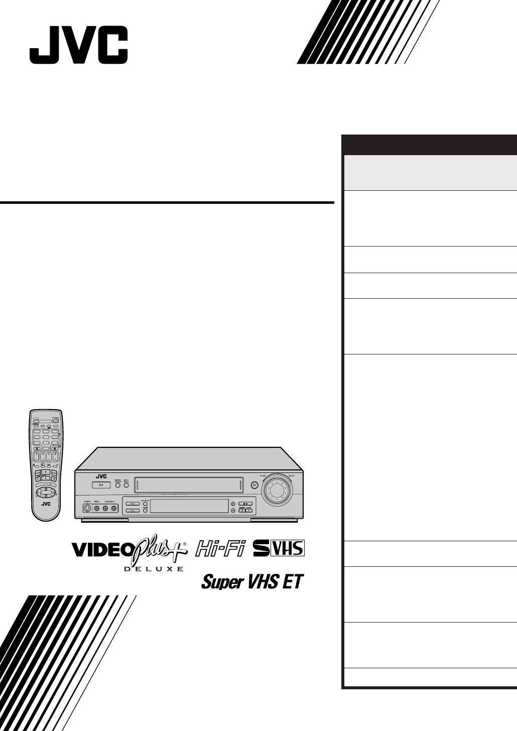
HR-S7700EK
HR-S7722EK
VIDEO CASSETTE RECORDER
INSTRUCTIONS
LPT0318-001A
625
T
V
P
R
+
T
V
P
R
–
T
V
–
T
V
+
TV
0000
STOP
FIN
MENU
OK
TV/VCR
DAILY/QTDN.
VPS/PDC
AUX
?
WEEKLY/HEBDO
PROG 30 SEC
– –:– –
AUDIO
123
465
789
0
DATE
START
DEBUT
PR
2
4
1
3
E
N
T
E
R
/
E
N
T
R
E
E
EXPRESS
CONTENTS
SAFETY FIRST 2
Safety Precautions.............................2
Some Do's And Don'ts .....................4
QUICK SET UP GUIDE 5
CHECK THE CONTENTS ..................5
INSTALLATION ................................6
AUTO SET UP .................................. 8
PRESET DOWNLOAD ......................9
T-V LINK 11
T-V Link Functions .......................... 11
SATELLITE RECEIVER CONTROL 12
Satellite Receiver Control Setting ....12
BASIC OPERATIONS 14
Playback .........................................14
Recording .......................................16
VIDEO Plus+® Timer Programming ...18
Express Timer Programming ............20
ADVANCED OPERATIONS 24
Playback Picture Adjustment .......... 24
Selecting The Sound You Want ....... 25
Looking For The Scene You Want ...26
Recording According To Tape
Type................................................27
Playback/Recording According
To Tape Characteristics ...................28
Automatic Satellite Programme
Recording .......................................30
Minimizing Picture Degradation
While Editing .................................. 32
Edit From A Camcorder................... 33
Edit To Or From Another Video
Recorder .........................................34
Audio Dubbing ............................... 37
Insert Editing ...................................38
Other Functions ..............................40
SYSTEM CONNECTIONS 44
Connection To A Stereo System ......44
SUBSIDIARY SETTINGS 45
VIDEO Plus+® Setup .......................45
Video Channel Set ..........................46
Tuner Set.........................................48
Clock Set ........................................55
SUBSIDIARY INFORMATION 56
Questions And Answers ..................56
Troubleshooting ..............................57
Index ..............................................59
SPECIFICATIONS Back Cover
2
SAFETY FIRST
Safety Precautions
Blue to N (Neutral) or Black
Brown to L (Live) or Red
625
IMPORTANT
nPlease read the various precautions on page 2 – 4 of this instruction manual before installing or operating the
recorder.
nIt should be noted that it may be unlawful to re-record pre-recorded tapes, records, or discs without the consent
of the owner of copyright in the sound or video recording, broadcast or cable programme and in any literary,
dramatic, musical, or artistic work embodied therein.
IMPORTANT
Connection to the mains supply in the United Kingdom.
DO NOT cut off the mains plug from this equipment. If the plug fitted is not suitable for the power points in your
home or the cable is too short to reach a power point, then obtain a proper safety approved extension lead/
adapter or consult your dealer.
In the unlikely event of the plug fuse failing be sure to replace the fuse only with an identical approved type, as
originally fitted, and to replace the fuse cover. If the fuse fails again consult your nearest JVC dealer.
If nonetheless the mains plug is cut off remove the fuse and dispose of the plug immediately, to avoid a possible
shock hazard by inadvertent connection to the mains supply.
If this product is not supplied fitted with a mains plug then follow the instructions given below:
DO NOT make any connection to the Larger Terminal coded E or Green.
The wires in the mains lead are coloured in accordance with the following code:
If these colours do not correspond with the terminal identifications of your plug, connect as follows:
Blue wire to terminal coded N (Neutral) or coloured Black.
Brown wire to terminal coded L (Live) or coloured Red.
If in doubt — consult a competent electrician.
The rating plate and the safety caution are on the rear of the unit.
WARNING: DANGEROUS VOLTAGE INSIDE
WARNING: TO PREVENT FIRE OR SHOCK HAZARD, DO NOT EXPOSE THIS UNIT TO RAIN
OR MOISTURE.
nCassettes marked "S-VHS" and "VHS" can be used with this video cassette recorder. However, S-VHS recordings are possible only
with cassettes marked "S-VHS".
By using the S-VHS ET function, it is possible to record and play back with S-VHS picture quality on VHS cassettes with this
recorder.
nVIDEO Plus+ and PlusCode are registered trademarks of Gemstar Development Corporation. The VIDEO Plus+ system is manufac-
tured under license from Gemstar Development Corporation.
3
Video tapes recorded with this video recorder in the LP (Long Play) mode cannot be played back on a single-
speed video recorder.
The STANDBY/ON button does not completely shut off mains power from the unit, but switches operating
current on and off. " " shows electrical power standby and " " shows ON.
Failure to heed the following precautions may result in damage to the recorder, remote control or video
cassette.
1. DO NOT place the recorder . . .
... in an environment prone to extreme temperatures or humidity.
... in direct sunlight.
... in a dusty environment.
... in an environment where strong magnetic fields are generated.
... on a surface that is unstable or subject to vibration.
2.DO NOT block the recorder’s ventilation openings.
3.DO NOT place heavy objects on the recorder or remote control.
4.DO NOT place anything which might spill on top of the recorder or remote control.
5.AVOID violent shocks to the recorder during transport.
MOISTURE CONDENSATION
Moisture in the air will condense on the recorder when you move it from a cold place to a warm place, or under
extremely humid conditions—just as water droplets form in the surface of a glass filled with cold liquid. Moisture
condensation on the head drum will cause damage to the tape. In conditions where condensation may occur, keep
the recorder turned on for a few hours to let the moisture dry.
CAUTION
nWhen you are not using the recorder for a long period of time, it is recommended that you disconnect the
power cord from the mains outlet.
nDangerous voltage inside. Refer internal servicing to qualified service personnel. To prevent electric shock or
fire hazard, remove the power cord from the mains outlet prior to connecting or disconnecting any signal lead
or aerial.

4
This equipment has been designed and manufactured to meet international safety standards but, like any
electrical equipment, care must be taken if you are to obtain the best results and safety is to be assured.
DO read the operating instructions before you attempt to use the equipment.
DO ensure that all electrical connections (including the mains plug, extension leads and interconnec-
tions between pieces of equipment) are properly made and in accordance with the manufacturer's
instructions. Switch off and withdraw the mains plug when making or changing connections.
DO consult your dealer if you are ever in doubt about the installation, operation or safety of your equip-
ment.
DO be careful with glass panels or doors on equipment.
DON'T continue to operate the equipment if you are in any doubt about it working normally, or if it is
damaged in any way — switch off, withdraw the mains plug and consult your dealer.
DON'T remove any fixed cover as this may expose dangerous voltages.
DON'T leave equipment switched on when it is unattended unless it is specifically stated that it is de-
signed for unattended operation or has a standby mode. Switch off using the switch on the
equipment and make sure that your family knows how to do this. Special arrangements may need
to be made for infirm or handicapped people.
DON'T use equipment such as personal stereos or radios so that you are distracted from the requirements
of road safety. It is illegal to watch television whilst driving.
DON'T listen to headphones at high volume, as such use can permanently damage your hearing.
DON'T obstruct the ventilation of the equipment, for example with curtains or soft furnishings. Overheat-
ing will cause damage and shorten the life of the equipment.
DON'T use makeshift stands and NEVER fix legs with wood screws — to ensure complete safety always
fit the manufacturer's approved stand or legs with the fixings provided according to the instruc-
tions.
DON'T allow electrical equipment to be exposed to rain or moisture.
ABOVE ALL...
—NEVER let anyone especially children push anything into holes, slots or any other opening in the
case — this could result in a fatal electrical shock;
—NEVER guess or take chances with electrical equipment of any kind — it is better to be safe than
sorry!
Some Do's And Don'ts On The Safe
Use Of Equipment
SAFETY FIRST (cont.)
5
QUICK SET UP GUIDE
T
V
P
R
+
T
V
P
R
–
T
V
–
T
V
+
TV
0000
STOP
FIN
MENU
OK
TV/VCR
DAILY/QTDN.
VPS/PDC
AUX
?
WEEKLY/HEBDO
PROG 30 SEC
– –:– –
AUDIO
123
465
789
0
DATE
START
DEBUT
PR
2
4
1
3
E
N
T
E
R
/
E
N
T
R
E
E
EXPRESS
STEP
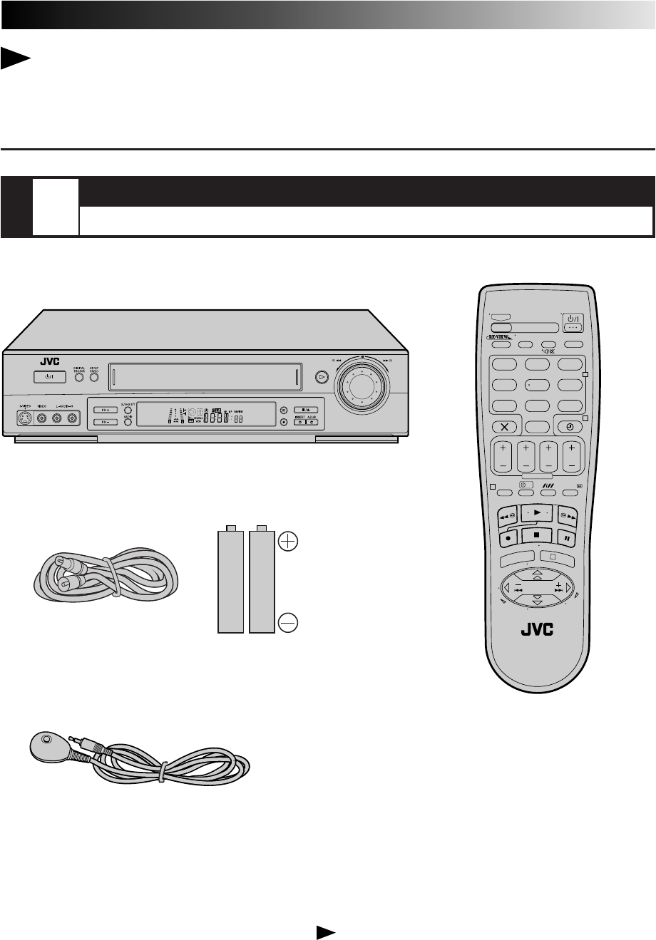
1CHECK THE CONTENTS
CHECK ALL THE CONTENTS SHOWN BELOW
Dear Customer,
Thank you for purchasing this JVC Video Cassette Recorder.
Please use this QUICK SET UP GUIDE to help you to set up your video cassette
recorder.
Video Cassette Recorder
Infrared Remote Control Unit
RF Cable
"AA" Batteries (x 2)
You are now ready to install your video recorder.
Satellite Controller
6
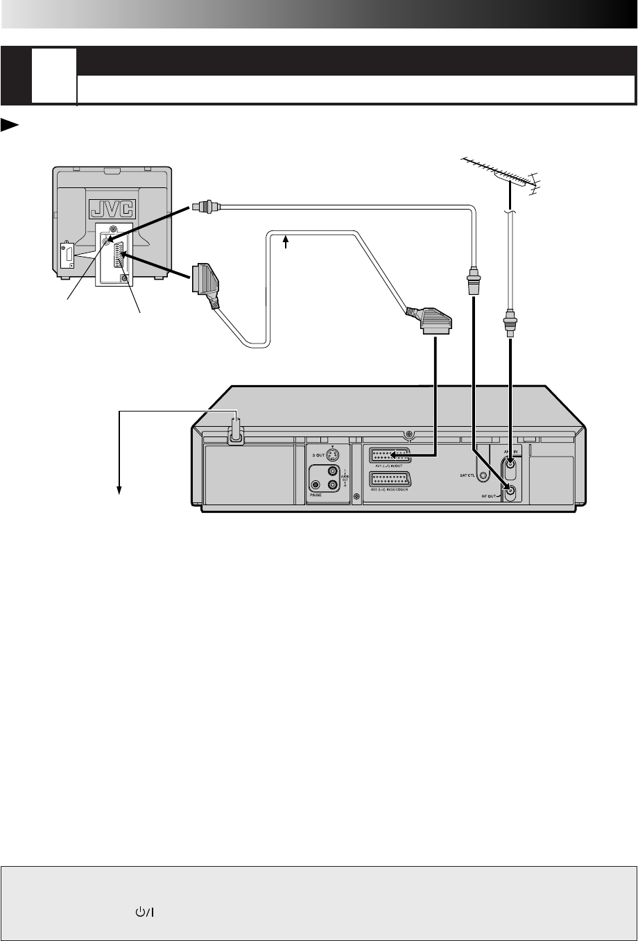
AV CONNECTION
To connect to a TV with 21-pin AV input connector (SCART) . . .
1– Connect the aerial, recorder and TV as per “RF CONNECTION”.
2– Connect an optional SCART cable between the AV1 (L-1) IN/
OUT socket on the rear panel of the recorder and the TV’s 21-
pin AV input connector (SCART).
NOTES:
●
The AV1 (L-1) IN/OUT connector accepts and delivers either
a composite signal (regular video signal) or a Y/C signal (a
signal in which the luminance and chrominance signals are
separated). If your TV's 21-pin AV input connector (SCART) is
compatible with the Y/C signal, set "L-1 OUTPUT" to
"S-VIDEO" after the connection and the initial settings are
completed (
Z
pg. 36). You can obtain high-quality S-VHS
pictures. (For connection, be sure to use a 21-pin SCART
cable that is compatible with the Y/C signal.)
●
Set your TV to the VIDEO (or AV), Y/C, or RGB mode
according to the type of your TV's SCART connector.
●
For switching the TV's mode, refer to the instruction manual
of your television.
●
To obtain high-quality S-VHS pictures, you can also use the
S-VIDEO CONNECTION described on page 7.
STEP
2INSTALLATION
CONNECT VIDEO RECORDER TO TV
Place the recorder on a stable, flat surface.
Make this connec-
tion if your TV has
a 21-pin AV input
connector (SCART) in
order to reduce the
possibility of interference.
And if you are using a stereo
TV, you will need this cable
in order to enjoy stereo
playback of videotapes.
RF CONNECTION
To connect to a TV with NO 21-pin AV input connector
(SCART) . . .
1– Disconnect the TV aerial cable from the TV.
2– Connect the TV aerial cable to the ANT. IN jack on the rear
panel of the recorder.
3– Connect the provided RF cable between the RF OUT jack on
the rear panel of the recorder and the TV’s aerial connector.
ATTENTION
nDo NOT Plug the mains power cord into a mains outlet until all connections are completed.
nDo NOT press the button on the recorder or on the remote control to turn on the recorder's
power before you start the Auto Set Up procedure described on page 8.
21-pin AV input connector
(SCART)
Aerial connector
Back of TV
21-pin SCART Cable (not provided)
RF Cable (provided)
TV Aerial Cable
(not provided)
Mains Power
Cord
Back of Recorder
Mains outlet
QUICK SET UP GUIDE (cont.)
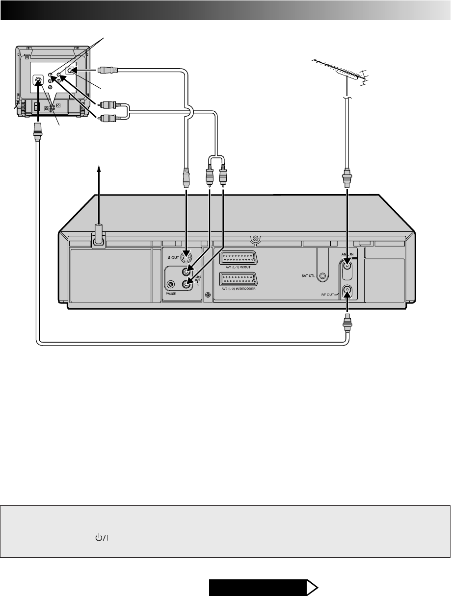
7
NOTES:
●
You can obtain high-quality S-VHS pictures.
●
With S-VIDEO connection, you cannot use the Preset
Download function. (
Z
pg. 9)
●
If your television is not stereo-capable, use the recorder's
AUDIO OUT connectors to connect to an audio amplifier for
Hi-Fi stereo sound reproduction. (
Z
pg. 44)
●
To operate the recorder with your TV using the S-VIDEO
connection, set your TV to the VIDEO (or AV mode).
●
For switching the TV's mode, refer to the instruction manual
of your television.
ATTENTION
nDo NOT Plug the mains power cord into a mains outlet until all connections are completed.
nDo NOT press the button on the recorder or on the remote control to turn on the recorder's
power before you start the Auto Set Up procedure described on page 8.
Go to Step 3 – AUTO SET UP
AFTER YOU FINISH THIS STEP
Mains outlet
Mains Power Cord
Back of Recorder
Aerial connector
RF Cable (provided)
Back of TV
S-Video cable
(not provided)
Audio cable
(not provided)
S-VIDEO IN connector
AUDIO IN connectors
S-VIDEO CONNECTION
To connect to a TV with S-VIDEO/AUDIO IN connectors . . .
1– Connect the aerial, recorder and TV as per "RF CONNEC-
TION" (Z pg. 6).
2– Connect the recorder's S OUT connector to the TV's
S-VIDEO IN connector.
3– Connect the recorder's AUDIO OUT connectors to the TV's
AUDIO IN connectors.
8
?
– –:– –
123
465
789
0
2
4
1
3
QUICK SET UP GUIDE (cont.)
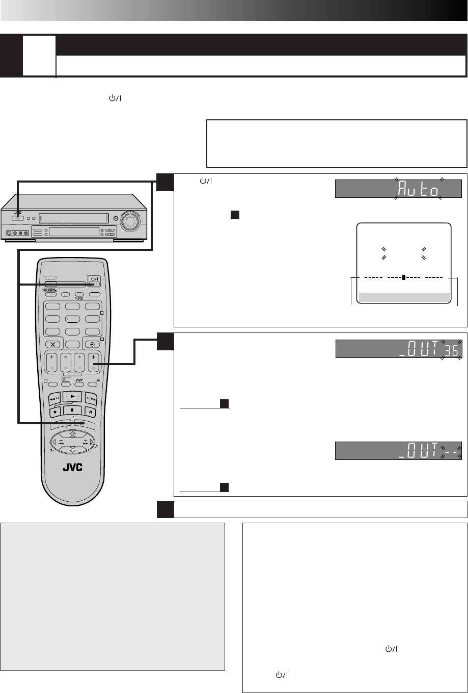
STEP
3AUTO SET UP
SET THE TUNER CHANNELS, CLOCK, GUIDE PROGRAM NUMBERS AND VIDEO CHANNEL*
The Auto Set Up function sets the tuner channels, clock, the VIDEO Plus+ assigned Guide Program numbers and the video channel*
automatically the first time the button on the recorder or on the remote is pressed to turn on the recorder after the mains power
cord has been plugged into a mains outlet.
Before performing the following procedure, make sure that:
nthe TV aerial cable is connected to the recorder.
nthe mains power cord is plugged into the mains outlet.
nbatteries have been installed in the remote control.
1
ATTENTION
Once you have performed Auto Set Up, all the stored
stations, Guide Program numbers and the video channel
remain in the recorder's memory and the recorder will not
perform Auto Set Up again. If there is a power cut and the
recorder's memory backup expires you only need to reset
the clock. (Z pg. 55)
If you have moved to a different area, perform each setting
as required.
nVideo Channel setting (for RF connection users) Z pg. 46
nTuner setting Z pg. 48
nClock setting Z pg. 55
If a new station begins broadcasting in your area, perform
tuner setting (Z pg. 48) and, if necessary, video channel
setting (Z pg. 46).
0
+++
Beginning End
* Useful if you have connected the video recorder to
your TV via RF connection (
Z
pg. 6). Video
Channel (RF output channel) is the channel on
which your TV receives picture and sound signals
from the video recorder through the RF cable.
NOTES:
●
Auto channel set function takes place first; it assigns
automatically all receivable stations in your area.
●
Auto clock set function sets the clock automatically.
●
During auto channel set, the recorder recognizes each
station name of the detected stations and stores them in
the recorder's memory, then automatically sets the VIDEO
Plus+ assigned Guide Program numbers for those stations
according to the broadcast area.
●
For RF connection users: The video recorder detects the
channels which are not occupied by local stations and
selects one channel automatically for your Video Channel
that is located in the middle of more than 5 vacant channels.
●
If there is a power cut or if you press or MENU while
Auto Set Up is in progress, Auto Set Up will be inter-
rupted; be sure to turn off the recorder power once and
press to turn the power back on in order to re-start
Auto Set Up.
AUTO SET
PLEASE WAIT
[MENU] : EXIT
3
Press OK to finish Auto Set Up and refer to page 10 to check the results.
●
If you have connected the video
recorder to your TV via the provided
RF cable only (RF connection) —
the channel that is shown on the display panel is your Video Channel.
To view picture signals from the video recorder, set your TV to the Video
Channel. — Refer to the instructions supplied with your TV set for how to do
this.
Go to item
3
.
●
If you have connected the video recorder to your TV via both the provided RF
cable and a 21-pin SCART cable (AV connection)
—
you do not need the video channel so you have to set the video channel to off.
Press PR – until the display panel
shows "_OUT– –" to set the Video
Channel to off.
To view picture signals from the video recorder, set your TV to its AV mode.
— Refer to the instructions supplied with your TV set for how to do this.
Go to item
3
.
2
Press . If "Auto" appears on the display
panel, press OK or
#
. "Auto" blinks; do
NOT press any button on the recorder or
remote control until the display panel shows either the display as illustrated
below in item
2
or "– – :– –". Auto Set Up usually takes about 4 – 12 minutes;
the duration varies by area.
●If "– –:– –" appears on the display panel,
refer to page 10.
●With the AV or S-VIDEO connection
(Z pg. 6, 7), if the TV is turned on and set to its
AV mode, the AUTO SET screen will appear.
●When you have connected the video recorder
to a TV offering T-V Link via the AV connec-
tion (Z pg. 6) and the TV is turned on, the
recorder automatically performs the Preset
Download (Z pg. 9) even if you select
"Auto" for Auto Set Up function.
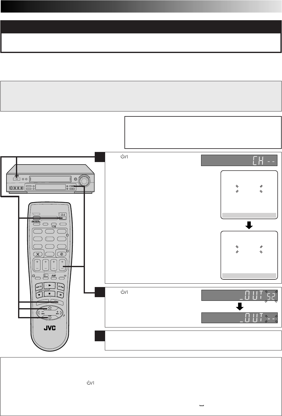
9
PRESET DOWNLOAD
SET THE TUNER CHANNELS BY DOWNLOADING FROM YOUR TV, CLOCK AND GUIDE PROGRAM
NUMBERS
Before performing the following procedure, make sure that:
nthe TV aerial cable is connected to the recorder and a 21-pin
SCART cable is connected between your TV and the recorder.
nthe mains power cord is plugged into the mains outlet.
nbatteries have been installed in the remote control.
1
Press to turn off the recorder. Press
and hold down STOP on the recorder
until the display panel shows the display
as illustrated on the right. Press PR – until
the display panel shows "_OUT– –" to set
the Video Channel to off.
2
Press . If "Auto" appears on the display
panel, Press %fi to select "CH – –" and
press OK or
#
. Preset position on the
display panel increases from "CH1";
do NOT press any button on the recorder
or remote control until the display panel
shows either the display as illustrated on
page 8 or "– – :– –".
●If "– –:– –" appears on the display panel, refer
to page 10.
●If you are using the on-screen display, the T-V
LINK screen will appear. Then the GUIDE
PROG SET screen will appear during Guide
Program number set.
●If you press any button on the recorder or
remote control while downloading is in
progress, this process will be interrupted and
you will need to start again. See NOTES below.
When you connect the recorder and your TV via fully-wired 21-pin SCART cable (Z pg. 6), you can set the recorder's tuner channels
by downloading preset data from your TV instead of using the Auto Set Up function (Z pg. 8). After downloading is completed, the
recorder sets the clock and the VIDEO Plus+ assigned Guide Program numbers automatically.
For details, refer to the instruction manual for your TV.
NOTES:
●
In areas where no TV station transmits the PDC signal, the recorder cannot perform either auto clock set or auto Guide Program
number set.
●
If there is a power cut, or if you press or MENU while downloading or set up is in progress, it will be interrupted; be sure to
turn off the recorder power once and try again from the beginning.
●
Auto clock may not function properly depending on reception conditions.
●
When you perform Preset Download, be sure to use fully-wired 21-pin SCART cable.
●
On this recorder, the characters available for station names (ID) are A–Z, 0–9, –, *, + and (space). The names of some
downloaded stations may differ from those on your TV (
Z
pg. 52).
ATTENTION
You can use this function only with a TV offering T-V Link, etc.*
* Compatible with TVs offering T-V Link, EasyLink, Megalogic, SMARTLINK, Q-Link, DATA LOGIC or NexTView Link via fully-wired 21-pin
SCART cable. The degree of compatibility and available functions may differ by system.
T-V LINK
PLEASE WAIT
[MENU] : EXIT
GUIDE PROG SET
PLEASE WAIT
[MENU] : EXIT
3
Press OK to exit Video Channel Set mode.
To view picture signals from the video recorder, set your TV to its AV mode.
— Refer to the instructions supplied with your TV set for how to do this.
?
– –:– –
123
465
789
0
2
4
1
3
10
IMPORTANT
nIn certain reception conditions, station names may not be stored correctly, and auto Guide Program Number Set may not work
properly. If the Guide Program numbers are not set properly, when you timer-record a TV programme using the VIDEO Plus+
system, the recorder will record a TV programme of a different station. When programming the timer using the VIDEO Plus+
system, be sure to check that the preset position corresponding to the broadcasting station you wish to record has been
selected (Z pg. 18, "VIDEO Plus+ Timer Programming").
nYour video recorder memorizes all detected stations even if reception of some of them is poor. In these cases picture quality
may be poor. To delete those stations which have an unacceptable picture Z "Delete A Channel" on page 51.
nIf any of the above problems occur, refer to pages 50 – 52 to input station names (Z "Set Stations") or delete unnecessary
stations (Z "Delete A Channel"). You can also change station preset positions (Z "Change Station Preset Position").
nFor RF connection users: In certain reception conditions, the Video Channel may not be set correctly and interference may
appear in the TV picture while the recorder's power is on. Set your Video Channel manually. Z pg. 46, "Video Channel Set".
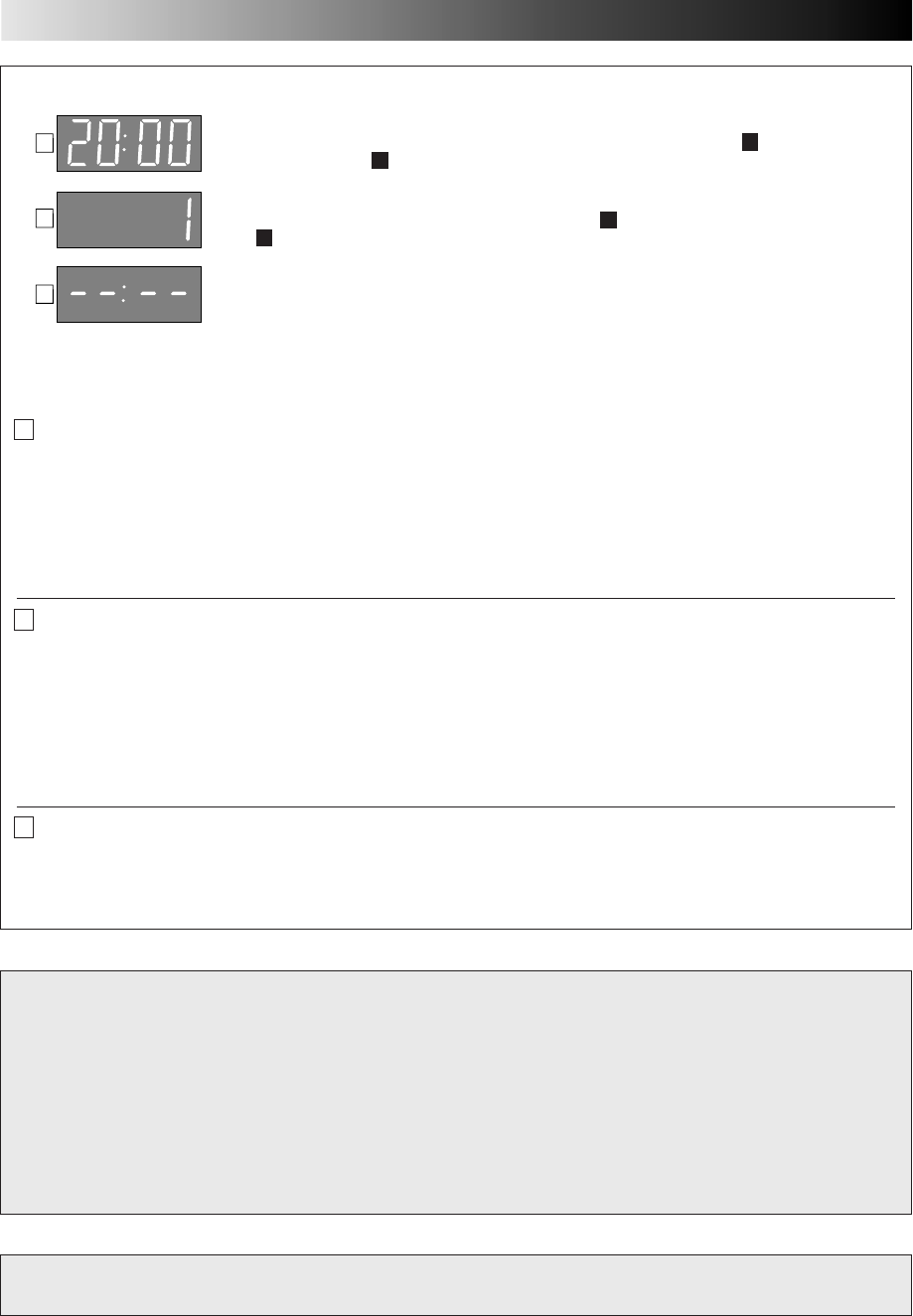
Auto Set Up/Preset Download results appear on the display panel
When neither auto channel set nor auto clock set has been completed successfully, "– –:– –"
will be displayed.
* You can check if the Guide Program numbers have been set correctly when you perform VIDEO Plus+ Timer Programming
(Z pg. 18); if the correct preset position number is displayed in step 3, this confirms that the Guide Program number for the
PlusCode number you enter in step 2 has been set correctly.
A If both auto channel set and auto clock set have been performed successfully:
1Turn on the TV and select its VIDEO channel or AV mode, then make sure that all necessary stations have been stored in the
recorder's memory by using the PR button(s).
●If station names (ID — Z pg. 53) have also been stored in the recorder's memory, the station name will be displayed at the
top left corner of the screen for about 5 seconds each time the recorder is tuned to a different station.
●If you want to set the tuner manually such as to add or skip channels, to change preset positions, or to set or change station
names, see pages 50 – 52.
Now you have finished the basic set up and can use your recorder for both playback and recording.
B If auto channel set has succeeded but auto clock set has not:
1Turn on the TV and select its VIDEO channel or AV mode, then make sure that all necessary stations have been stored in the
recorder's memory by using the PR button(s).
●If station names (ID — Z pg. 53) have also been stored in the recorder's memory, the station name will be displayed at the
top left corner of the screen for about 5 seconds each time the recorder is tuned to a different station.
●If you want to set the tuner manually such as to add or skip channels, to change preset positions, or to set or change station
names, see pages 50 – 52.
2Perform "Clock Set" on page 55.
Now you have finished the basic set up and can use your recorder for both playback and recording.
C If both auto channel set and auto clock set have failed:
1Make sure that the TV aerial cable is connected properly to the recorder (for RF connection), or that the 21-pin SCART cable
is connected properly between TV and the recorder (for AV connection). Turn off the recorder power once, then turn the
recorder power back on again.
2Perform "Auto Set Up" on page 8 or "Preset Download" on page 9.
If you have any difficulty with the above procedures call the JVC Customer Service Hot Line
on 020 8208 7654
A
B
C
When both auto channel set and auto clock set have been completed successfully the
correct current time will be displayed after the OK button is pressed in item
3
on page 8 or
after performing item
1
on page 9.
When auto channel set has been completed successfully but auto clock set has not, "(PR)1"
will be displayed after the OK button is pressed in item
3
on page 8 or after performing
item
1
on page 9.
QUICK SET UP GUIDE (cont.)
11
T-V LINK
T-V Link
Functions
When you connect the recorder and your TV via a fully-wired
21-pin SCART cable (Z pg. 6), the following functions are
available. You can use these functions only with a TV offering
T-V Link, etc.*
For details, refer to the instruction manual for your TV.
* Compatible with TVs offering T-V Link, EasyLink, Megalogic,
SMARTLINK, Q-Link, DATA LOGIC or NexTView Link via fully-
wired 21-pin SCART cable. The degree of compatibility and
available functions may differ by system.
NexTView Link
You can download the EPG (Electronic Programme Guide)
information from your TV for timer-programming on the
recorder.
For details, refer to the instruction manual for your TV.
TV Auto Power On
You can turn on the TV and set it to video mode automatically
whenever you play a tape.
For details, refer to the instruction manual for your TV.
VCR Auto Standby
You can use your TV's remote control to turn off the recorder.
For details, refer to the instruction manual for your TV.
Direct Rec
You can start recording the programme that you are watching
on your TV with simple operation. Press and hold RECORD and
press PLAY on the remote control, or press RECORD on the
recorder.
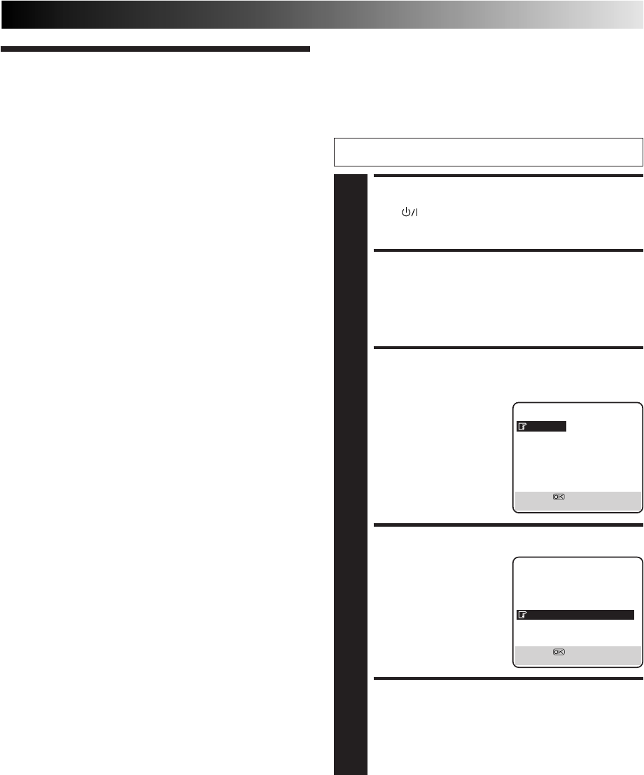
Follow the procedure below to use this function.
TURN ON THE RECORDER
1
Press .
ACCESS MAIN MENU
SCREEN
2
Press MENU.
ACCESS MODE SET
SCREEN
3
Press %fi to move the
highlight bar (pointer) to
"MODE SET", then press
OK or
#
.
SELECT DIRECT REC MODE
4
Press %fi to move the
highlight bar (pointer) to
"DIRECT REC", then press
OK or
#
to set to "ON".
RETURN TO NORMAL
SCREEN
5
Press MENU.
NOTES:
●
If "DIRECT REC" is set to "OFF", the RECORD button functions
as described in "Recording" (
Z
pg. 16).
●
During the Direct Rec, "– –" appears on the display panel.
●
When you perform T-V LINK functions, be sure to use a fully-
wired 21-pin SCART cable.
●
Direct Rec is not possible with a scrambled broadcast.
●
To record a scrambled broadcast, set "DIRECT REC" to "OFF"
and follow the procedure described in "Recording" on
page␣ 16.
●
Retake function (
Z
pg. 43) does not work during Direct Rec.
MAIN MENU
MODE SET
AUTO CH SET
MANUAL CH SET
OUTPUT/INPUT SET
INITIAL SET
T
[5∞] =
[MENU] : EXIT
MODE SET
B. E. S. T. ON
PICTURE CONTROL AUTO
AUTO TIMER OFF
O. S. D. ON
DIRECT REC ON
AUTO SP=LP TIMER OFF
DIGITAL 3R ON
NEXT PAGE
[5∞] =
[MENU] : EXIT
Turn on the TV and select the VIDEO channel (or AV mode).
12
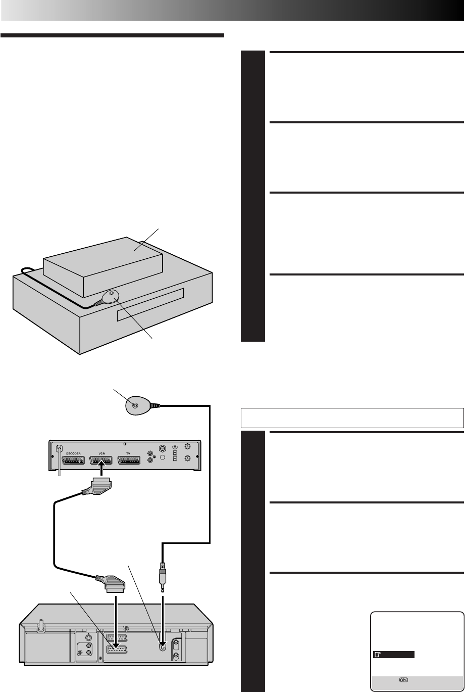
Installing Satellite Controller
SITUATE SATELLITE
CONTROLLER
1
Place the Satellite Controller so that the path between
its transmitter and the satellite receiver’s remote sensor
is unobstructed.
ATTACH SATELLITE
CONTROLLER
2
Fix securely using the adhesive strip attached on the
back of the Satellite Controller.
MAKE CONNECTIONS
3
Be sure to connect the recorder’s AV2 (L-2) IN/DECODER
connector to the satellite receiver’s 21-pin SCART connector.
NOTE:
When connecting your satellite receiver, refer to its
instruction manual.
CONNECT SATELLITE CON-
TROLLER TO RECORDER
4
Connect the Satellite Controller to the SAT CTL
connector on the rear panel.
Satellite
Receiver
Control Setting
The following procedure is required if you receive satellite
channels through a satellite receiver. Around 20 seconds before
VIDEO Plus+ timer recording (Z pg. 18) or Express timer
programming (Z pg. 20) starts, the recorder sets its input mode
to "L-2" and automatically switches the satellite receiver’s
channels using the provided Satellite Controller.
Your recorder
Back of Recorder
Satellite receiver
Satellite Controller
Satellite receiver
Satellite Controller
(suggested locations)
Transmitter
AV2 (L-2) IN/DECODER
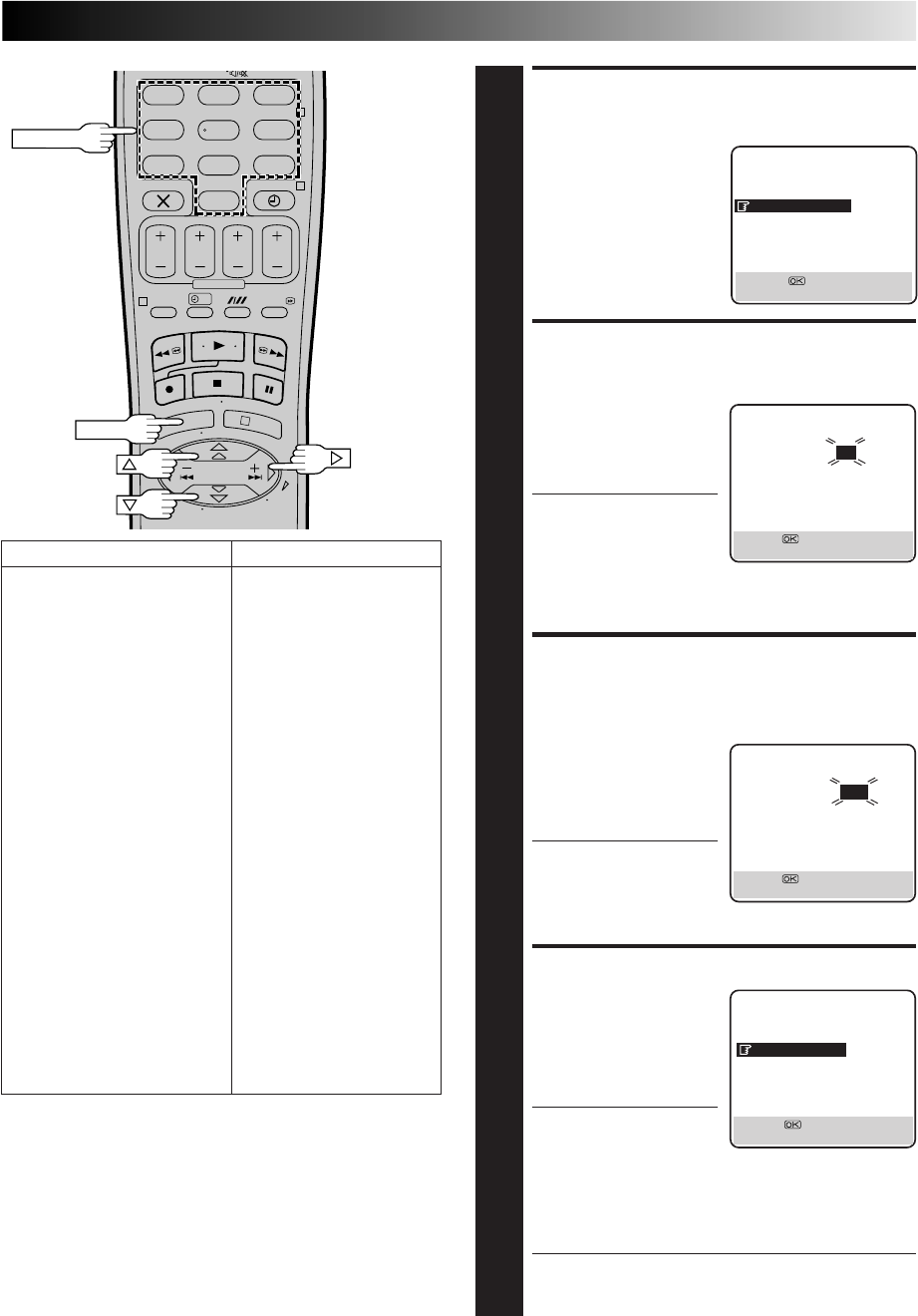
SATELLITE RECEIVER CONTROL
TURN ON SATELLITE
RECEIVER
1
Turn on the satellite receiver’s power.
ACCESS MAIN MENU
SCREEN ON RECORDER
2
Press MENU.
ACCESS INITIAL SET
SCREEN
3
Press %fi to move the
highlight bar (pointer) to
“INITIAL SET”, then press
OK or
#
.
MAIN MENU
MODE SET
AUTO CH SET
MANUAL CH SET
OUTPUT/INPUT SET
INITIAL SET
T
[5∞] =
[MENU] : EXIT
Setting satellite receiver's
brand and channel
After installation, set the satellite receiver’s brand and channel
correctly; otherwise, the Satellite Controller cannot work correctly.
Turn on the TV and select the VIDEO channel (or AV mode).
SAT CTL
21-pin SCART
cable
13
?
123
465
789
0
2
4
1
3
MENU
NUMBER
ACCESS SAT CONTROL
SET SCREEN
4
Press %fi to move the
highlight bar (pointer) to
“SAT CONTROL SET”,
then press OK or
#
.
ENTER SATELLITE
RECEIVER’S BRAND
5
Press the appropriate
NUMBER keys to enter the
brand code from the list in
the left column, then press
OK.
●If the brand code you
entered is invalid, the
code field is reset. Enter
the correct brand code
again.
●If the recorder is in playback or recording mode, you
cannot set the brand code.
SELECT SATELLITE
RECEIVER’S CHANNEL FOR
TESTING
6
Press the appropriate
NUMBER keys to enter
one of the channel
positions on the satellite
receiver, then press OK.
●You can select the
channel position
between 1 to 999.
●After pressing OK, the
recorder enters the Test mode.
CHECK RESULT OF TEST
7
If the satellite
receiver’s channel
number has been
changed to the same
channel as you set in
step 6...
Press %fi to move the
highlight bar (pointer) to
“CHANGED TO ...”, then
press OK or
#
to finish the
Sat Control Set mode.
If the satellite receiver’s channel number has not
been changed correctly...
Press %fi to move the highlight bar (pointer) to “NOT
CHANGED”, then press OK or
#
. Then perform the
procedure again from step 5.
SATELLITE TUNER BRAND CODE
JVC 73
AMSTRAD 60, 61, 62, 63, 92
CANAL SATELLITE 81
CANAL + 81
D-BOX 85
ECHOSTAR (VIA DIGITAL) 82
FINLUX 68
FORCE 89
GALAXIS 88
GRUNDIG 64, 65
HIRSCHMANN 64, 78
ITT NOKIA 68
JERROLD 75
KATHREIN 70, 71
LUXOR 68
MASCOM 93
MASPRO 70
NOKIA 87
PACE 65, 67, 74, 86, 92
PANASONIC 74
PHILIPS 66, 84
RFT 69
SAGEM 83
SALORA 68
SIEMENS 64
SKYMASTER 69
TPS 83
TRIAX 91
WISI 64
SAT CONTROL SET
BRAND : – –
[0–9] =
[MENU] : EXIT
SAT CONTROL SET
SAT PROG : – – –
[0–9] = : TEST
[MENU] : EXIT
SAT CONTROL SET
SAT PROG : 111
CHANGED TO 111
NOT CHANGED
[5∞] =
[MENU] : EXIT
INITIAL SET
CLOCK SET
GUIDE PROG SET
SAT CONTROL SET
[5∞] =
[MENU] : EXIT
NOTES:
●
The Satellite Controller may not work with all types of
satellite receiver.
●
For some satellite receivers, you need to set its channel input
mode to 2-digit.
●
If your satellite receiver has more than two channel mode, be
sure to set to "All Channel Mode". For details, refer to the
instruction manual of the satellite receiver.
●
When selecting the satellite receiver's channel (
Z
step 6),
signals from the remote control may interfere with signals
transmitted from the Satellite Controller. In this case, move
the remote control as close to the recorder's infrared beam
receiving window as possible.
14
BASIC OPERATIONS
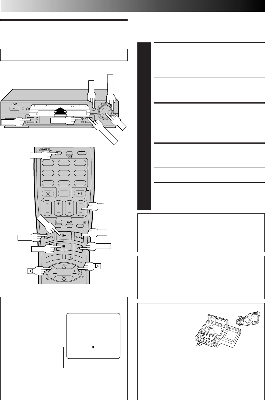
Playback
The easiest, most basic operation possible with your video
recorder is tape playback. Already-recorded signals on a video
tape are read by your video recorder and displayed on your TV
just like a TV programme.
LOAD A CASSETTE
1
Make sure the window side is up, the rear label side is
facing you and the arrow on the front of the cassette is
pointing towards the recorder. Don’t apply too much
pressure when inserting.
●The recorder power comes on automatically and the
counter is reset to 0:00:00.
●If the record safety tab has been removed, playback
begins automatically.
FIND PROGRAMME START
POINT
2
If the tape is advanced past the start point, press REW
or turn the SHUTTLE ring to the left. To go forward,
press FF or turn the SHUTTLE ring to the right.
START PLAYBACK
3
Press PLAY. "BEST" appears blinking in the recorder's
display panel during automatic tracking (Z pg. 28).
●Playback picture quality of LP recordings will not be
as high as SP recordings.
STOP PLAYBACK
4
Press STOP on the remote or STOP/EJECT on the
recorder’s front panel. Then press STOP/EJECT to
remove the cassette.
Turn on the TV and select the VIDEO channel (or AV mode).
?
– –:– –
123
465
789
0
2
4
1
3
PLAY
STOP
3
4
1
REW
2
FF
2
Usable cassettes
●Compact VHS
camcorder recordings
can be played on this
video recorder. Simply
place the recorded
cassette into a VHS
Cassette Adapter and it
can be used just like any full-sized VHS cassette.
●This video recorder can record on regular VHS and
Super VHS cassettes. While only VHS signals can be
recorded on regular VHS cassettes*, both VHS and Super
VHS signals can be recorded and played back using
Super VHS cassettes.
* By using the S-VHS ET function, it is possible to record
and play back with S-VHS picture quality on VHS
cassettes with this recorder.
3
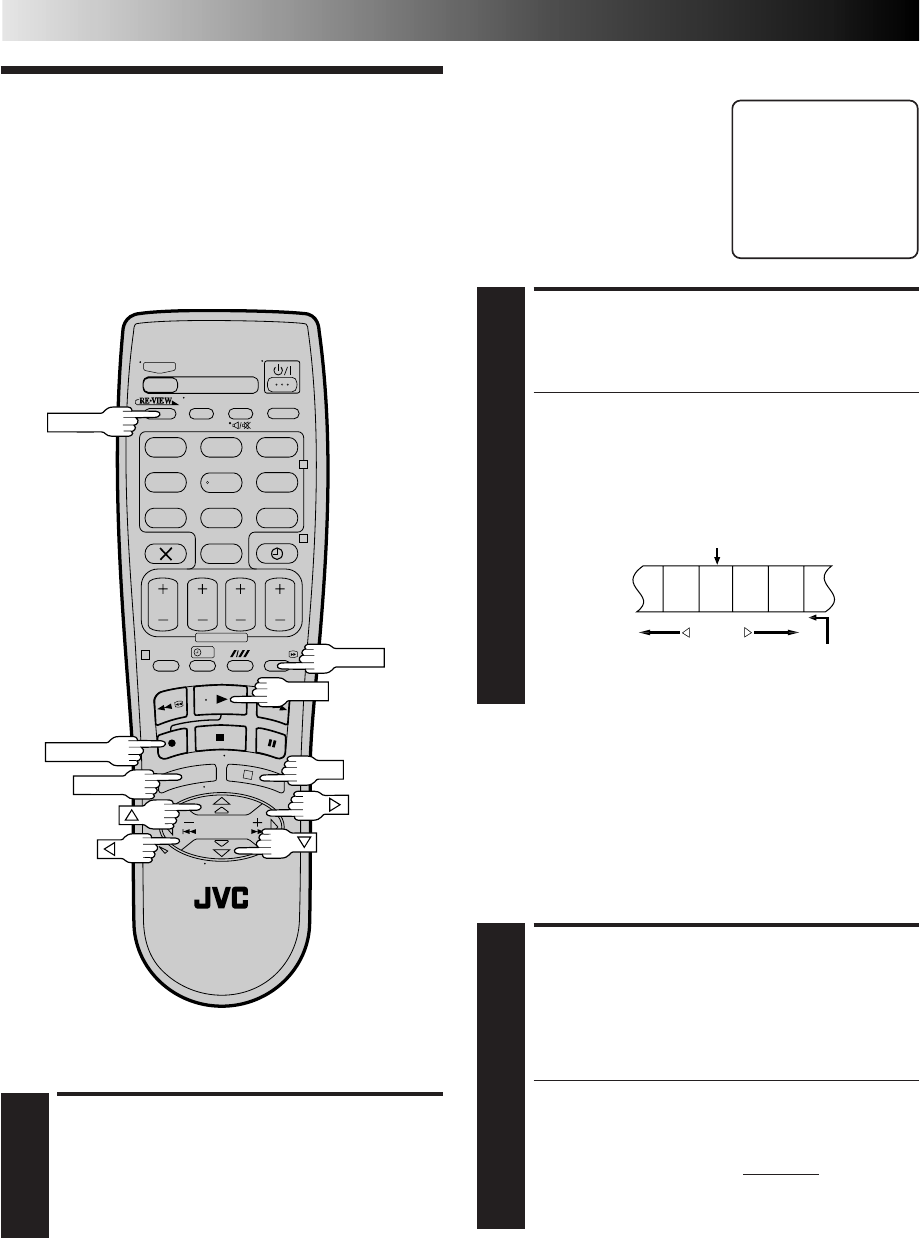
4
Tape Position Indicator
The tape position indicator
appears on screen when,
from the Stop mode, you
press FF, REW or perform an
Index Search. The position of
“5” in relation to “0”
(beginning) or “+” (end)
shows you where you are on
the tape.
”O.S.D.” (Z pg. 40) must
be set to “ON”, or the
indicator will not appear.
NOTE:
Depending on the type of tape used, there may be times
when the indication is not correct.
3
1:23:45
REMAIN 2:35
0
+++
Beginning End
INFORMATION
When using the AV connection (Z pg. 6), initiating playback
causes the VCR indicator to light and the TV to automatically
enter AV mode. To return the TV to TV mode after playback
is complete, press TV/VCR so that the VCR indicator turns off.
* Depending on the type of TV used, TV/VCR button does
not always function as described above.
2
PLAY
SHUTTLE
TV/VCR
PR+/–
PR
Clean the video heads using a dry cleaning
cassette — JVC TCL-2U — when:
●Rough, poor picture appears while a tape is played back.
●The picture is unclear or no picture appears.
●"USE CLEANING CASSETTE" appears on the screen (only
with "O.S.D." set to "ON" (Z pg. 40.)
JOG
STOP/EJECT
PAUSE
PAUSE
15
ATTENTION
●In the high-speed search, still, slow-motion or frame-by-
frame playback mode,
●the picture will be distorted.
●noise bars will appear.
●there will be a loss of colour with a tape recorded in LP
mode.
●Picture may not appear during high-speed search with a
tape recorded in LP mode.
●When normal playback resumes from search, still, slow
motion or frame-by-frame playback, the picture may
jitter vertically momentarily depending on the type of TV
being used.
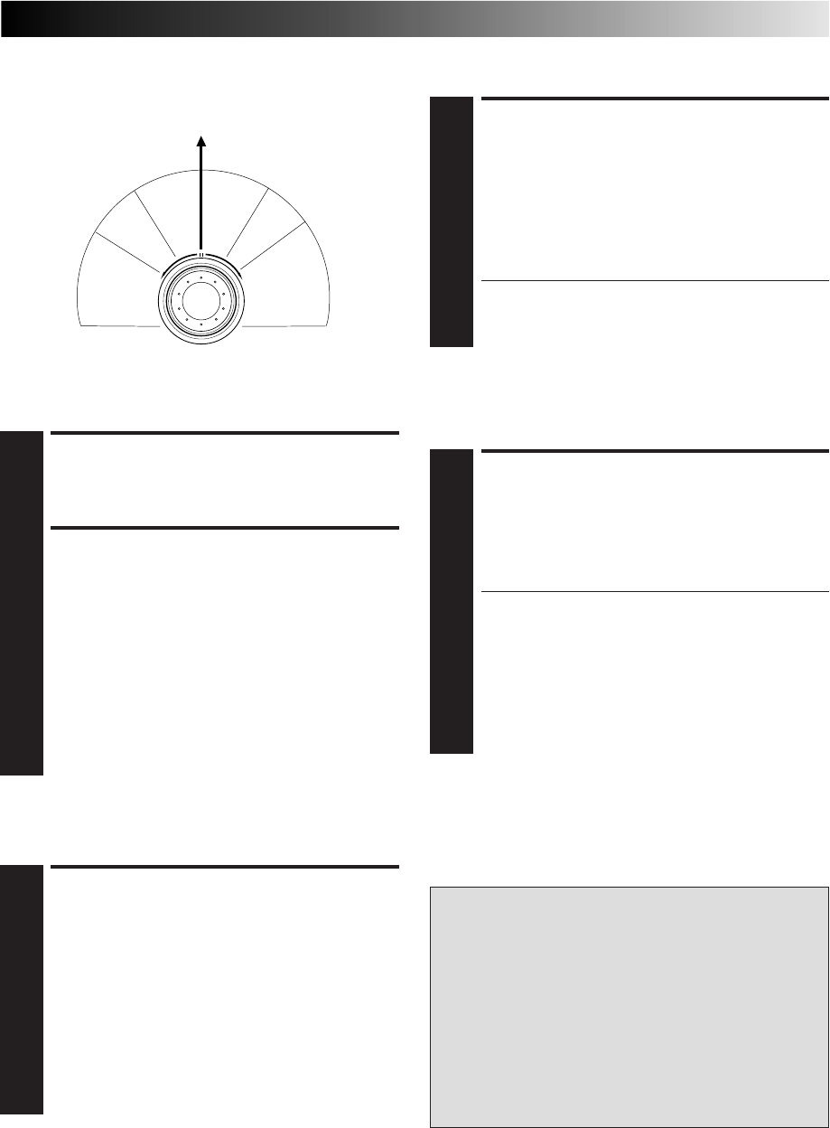
Slow Motion
ACTIVATE SLOW-MOTION
PLAYBACK
1
During playback or still picture, turn the SHUTTLE ring
to the right for forward slow motion, or to the left for
reverse slow motion (refer to the illustration above).
OR
During still picture, press and hold PAUSE for 2
seconds, then release. Press and release again to return
to still picture.
OR
During still picture, press and hold
@
or
#
. Release to
return to still picture.
To resume normal playback, press PLAY.
Still Picture/Frame-By-Frame
Playback
PAUSE DURING PLAYBACK
1
Press PAUSE. If there is vertical jitter, use the PR buttons
to correct the picture.
ACTIVATE FRAME-BY-FRAME
PLAYBACK
2
Turn the JOG dial to the right for forward frame-by-
frame playback, or to the left for reverse frame-by-frame
playback.
OR
Press PAUSE. Each time PAUSE is pressed the tape will
advance one frame.
OR
Press
@
or
#
. Each time one of these buttons is pressed
the tape will move one frame in the direction of the
arrow.
To resume normal playback, press PLAY.
NOTE:
Refer to the SHUTTLE ring illustration below as you read the
following procedures.
R
e
v
e
r
s
e
R
e
v
e
r
s
e
R
e
v
e
r
s
e
S
l
o
w
P
l
a
y
F
o
r
w
a
r
d
s
e
a
r
c
h
p
l
a
y
s
l
o
w
m
o
t
i
o
n
s
e
a
r
c
h
Still
High-Speed (Turbo) Search
ACTIVATE HIGH-SPEED
SEARCH
1
During playback or still, turn the SHUTTLE ring all the
way to the right for forward high-speed search, or to the
left for reverse high-speed search. Releasing SHUTTLE
resumes still picture playback.
●For forward high-speed search, turn the SHUTTLE
ring all the way to the right and release it within 1
second.
●For reverse high-speed search, turn the SHUTTLE ring
all the way to the left and release it within 1 second.
OR
During playback or still picture, press FF for forward
high-speed search, or REW for reverse high-speed
search.
To resume normal playback, press PLAY.
NOTE:
For short searches, press and hold FF or REW during playback or
still picture. When released, normal playback resumes.
ACTIVATE VARIABLE-SPEED
SEARCH
1
During playback or still, turn the SHUTTLE ring to the
right for forward variable-speed search, or to the left for
reverse variable-speed search (refer to the illustration on
the left).
OR
During playback, press
@
or
#
.
●The more times you press, the faster the playback
picture moves.
●To decrease speed, press the button for the opposite
direction.
To resume normal playback, press PLAY.
Variable-Speed Search
16
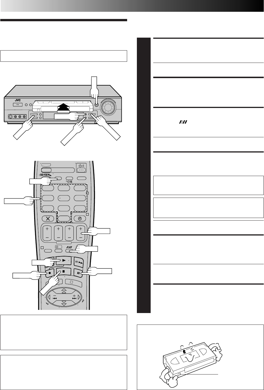
TV signals being received by the recorder’s built-in tuner can be
recorded onto a video tape. You can “capture” a TV programme
using your video recorder.
BASIC OPERATIONS (cont.)
Recording
Turn on the TV and select the VIDEO channel (or AV mode).
LOAD A CASSETTE
1
Insert a cassette with the record safety tab intact (See
below).
●The counter is reset to 0:00:00 and the recorder
power comes on automatically.
CHOOSE A PROGRAMME
2
Press PR +/– or the NUMBER keys to select the preset
you wish to record.
SET TAPE SPEED
3
Press SP/LP ( ). Check the SP/LP indicator on the
recorder display panel to confirm the selected tape
speed.
●Picture quality of LP recordings will not be as high as
on SP recordings.
START RECORDING
4
Press and hold RECORD and press PLAY on the remote
control, or press RECORD on the recorder.
● You can not change the preset whilst recording is in
progress. To change the preset, see step 5.
PAUSE/RESUME
RECORDING
5
Press PAUSE. Press PLAY to resume recording.
● During the Record Pause mode, you can change the
preset by pressing the PR +/– buttons or the NUMBER
keys.
STOP RECORDING
6
Press STOP on the remote control or STOP/EJECT on
the recorder. Then press STOP/EJECT to remove the
cassette.
?
– –:– –
123
465
789
0
2
4
1
3
PAUSE
5
4,5
RECORD
4
STOP
6
NUMBER
3
1
2
2
PLAY
5
6
5
RECORD
4
2
Accidental erasure prevention
●To prevent accidental recording on a recorded cassette,
remove its safety tab. To record on it later, cover the hole
with adhesive tape.
Record safety tab
B.E.S.T. takes place at the beginning of both the
first SP and the first LP recording after inserting the
cassette (Z pg. 28).
Recording Resume Function
If there is a power cut during recording (or Instant Timer
Recording or timer recording), the recording will resume
automatically when power is restored to the recorder
unless the recorder's memory backup has expired.
SP/LP
PLAY
INFORMATION
When using the AV connection (Z pg. 6), you can switch
between TV mode and AV mode by pressing TV/VCR.
* Depending on the type of TV used, TV/VCR button does
not function as described above.
If "DIRECT REC" is set to "ON", the programme
that appears on the TV screen will be recorded
(Z pg. 11). (Only with a TV offering T-V Link)
TV/VCR
PR+/–
PR+/–
PAUSE
STOP/EJECT
17
?
– –:– –
123
465
789
0
2
4
1
3
Record One Programme
While Watching Another
Elapsed Recording Time
Indication
You can check the exact time of a recording.
Tape Remaining Time
DISPLAY REMAINING TIME
1
Press – –:– – until the time remaining on the tape
appears.
●The display panel shows the tape remaining time
with " " displayed.
●By pressing the – –:– – button, you can change the
display to show the counter reading, preset position*,
clock time or tape remaining time.
* Preset position is not displayed during playback.
NOTE:
Depending on the type of tape used, there may be times when
the tape remaining time reading may not appear right away, or
is not correct. "– –:– –" may sometimes appear, or the display
may blink on occasion.
SET COUNTER DISPLAY
1
Press – –:– – until a counter reading appears on the
display panel.
RESET COUNTER
2
Press 0000 before starting recording or playback.
●The counter is reset to “0:00:00” and shows the exact
elapsed time as the tape runs.
SELECT PRESET TO WATCH
1
Once recording is in progress, all you need to do is to
set the preset controls on the TV for the station you
wish to view.
●The programme selected with the TV’s preset controls
appears on the TV screen while the one selected with
the recorder's PR buttons is recorded on the tape.
Instant Timer Recording (ITR)
This easy method allows you to record for any length of time
from 30 mins. to 6 hours (selectable in 30-min. increments),
and shuts off the recorder after recording is finished.
START RECORDING
1
Press RECORD on the recorder.
ENGAGE ITR MODE
2
Press RECORD again. " " blinks and 0:30 appears on
the front display panel.
SET RECORDING
DURATION
3
If you want to record for more than 30 minutes, press
RECORD to extend the time. Each press extends
recording time by 30 minutes.
NOTE:
You can only perform ITR using the RECORD button on the
recorder's front panel.
RECORD
0000
– –:– –
PR+/–
PR
18
?
– –:– –
123
465
789
0
2
4
1
3
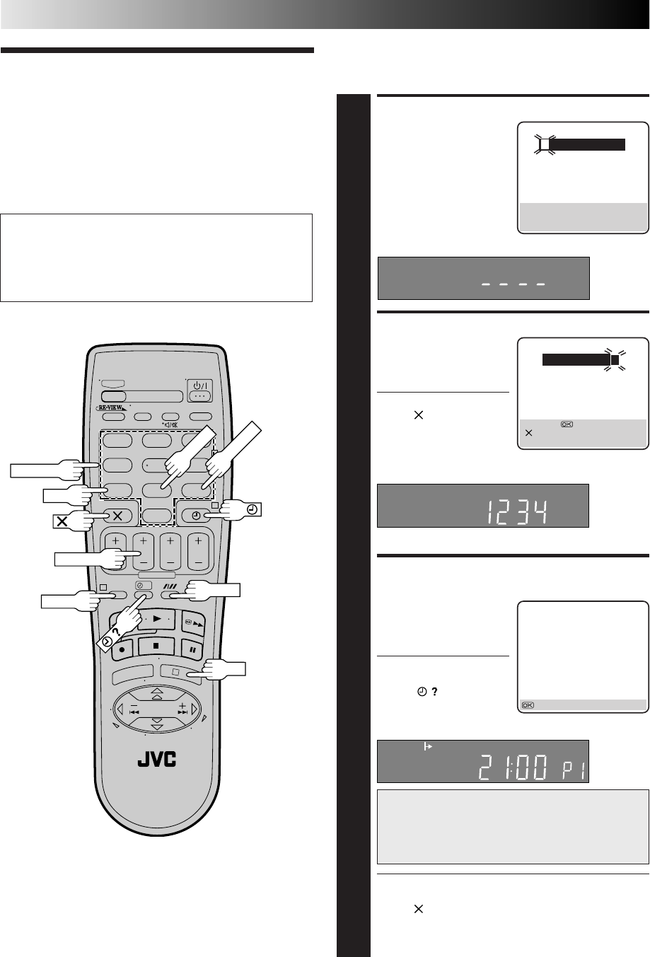
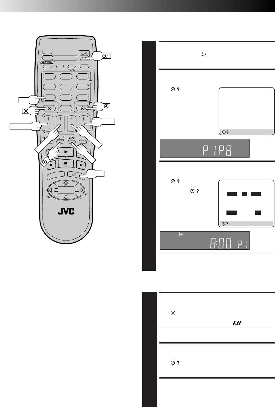
ACCESS VIDEO PLUS+ SCREEN
1
Press PROG.
The front display panel looks like this:
ENTER PLUSCODE NUMBER
2
Press the NUMBER keys to
enter the PlusCode
number of the programme
you wish to record.
●If you make a mistake,
press and input the
correct number.
The PlusCode number you enter appears on the front
display panel:
The display panel shows only a 4-digit number.
ACCESS VIDEO PLUS+ PROGRAM
SCREEN
3
Press OK, and the VIDEO
Plus+ Program screen
appears (if you’re just
starting out, “P1” appears).
The display panel shows the
programme start time.
Pressing changes the
display to the programme
stop time, then the date and
preset position.
IMPORTANT
Make sure the preset position number you wish to
record is displayed; if not, see "VIDEO Plus+ Setup"
on page 45 and set the Guide Program number for
that PlusCode number correctly.
●If the number you entered is invalid, "ERROR" appears
on the screen and "Err" appears on the display panel.
Press and input a valid PlusCode number.
●If the "GUIDE PROG SET" screen appears, see
"ATTENTION – Regarding Guide Program Number
Set" on page 19.
VIDEO Plus+
Timer
Programming
Before performing the VIDEO Plus+ Timer Programming:
●Make sure that the recorder's built-in clock is set
properly.
●Insert a cassette with the safety tab in place. The recorder
will come on automatically.
●Turn on the TV and select the VIDEO channel (or AV mode).
With the VIDEO Plus+ system, timer programming is greatly
simplified because each TV programme has a corresponding
code number which your recorder is able to recognise.
BASIC OPERATIONS (cont.)
OK
3,6
PROG
1,6
NUMBER
5
2
PDC
7
WEEKLY
DAILY
STOP+/–
VIDEO PLUS+
[0 – 9] = VIDEO PLUS+
[+/–] : EXPRESS PROGRAMING
[PROG] : EXIT
SP
VIDEO PLUS+
12345678
[0 – 9] =
[] : DELETE
[PROG] : EXIT
– P1 –
VIDEO PLUS+ 123456789
START STOP
21:00 =22:00
SP VPS/PDC OFF
DATE TV PROG
25.12 1
BBC 1
: OK
4
SP/LP
19
SET TAPE SPEED
4
Press SP/LP ( ) to set the tape speed.
SET PDC MODE
5
Press PDC to select "ON" or "OFF".
If "VPS/PDC ON" is displayed on the screen or "VPS/
PDC" is lit on the display panel, PDC is set to ON.
If "VPS/PDC OFF" is displayed on the screen or "VPS/
PDC" is not lit on the display panel, PDC is set to OFF.
Z "PDC Recording" in the column below.
●VPS (Video Programme System) recording is not
currently available in the U.K. and not possible with
this recorder.
RETURN TO NORMAL SCREEN
6
Press PROG or OK. "PROGRAM COMPLETED" appears
on the screen for about 5 seconds, then normal screen
appears. If the timer programme is overlapped with
another one that was already set, "PROGRAM
OVERLAPPED" appears on screen and "Err" appears on
the front display panel. (Z pg. 23)
●Repeat steps 1 – 6 for each additional programme.
ENGAGE RECORDER’S TIMER
MODE
7
Press ‰ (TIMER). The recorder turns off automatically
and ‰ appears on the display panel.
●To disengage the timer, press ‰ (TIMER) again.
NOTES:
●
To Change The Stop Time . . .
. . . press STOP +/– after pressing OK in step 3. You can
compensate for anticipated programme schedule delays this
way.
●
To Timer-Record Weekly Or Daily Serials . . .
. . . after pressing OK in step 3, press WEEKLY (NUMBER key
“9”) for weekly serials or DAILY (NUMBER key “8”) for daily
serials (Monday – Friday). Either "WEEKLY" or "DAILY"
appears on the screen. Pressing the button again makes the
corresponding indication disappear.
●
You can programme this recorder to timer-record as many as 8
programmes. If you try to programme the recorder to record a
ninth, "PROGRAM FULL" appears on screen and "FULL"
appears on the front display panel. To record the extra
programme, you must first cancel any unnecessary
programmes (
Z
pg. 22).
●
It is not possible to timer-record a TV programme with a
PlusCode number which starts with "0".
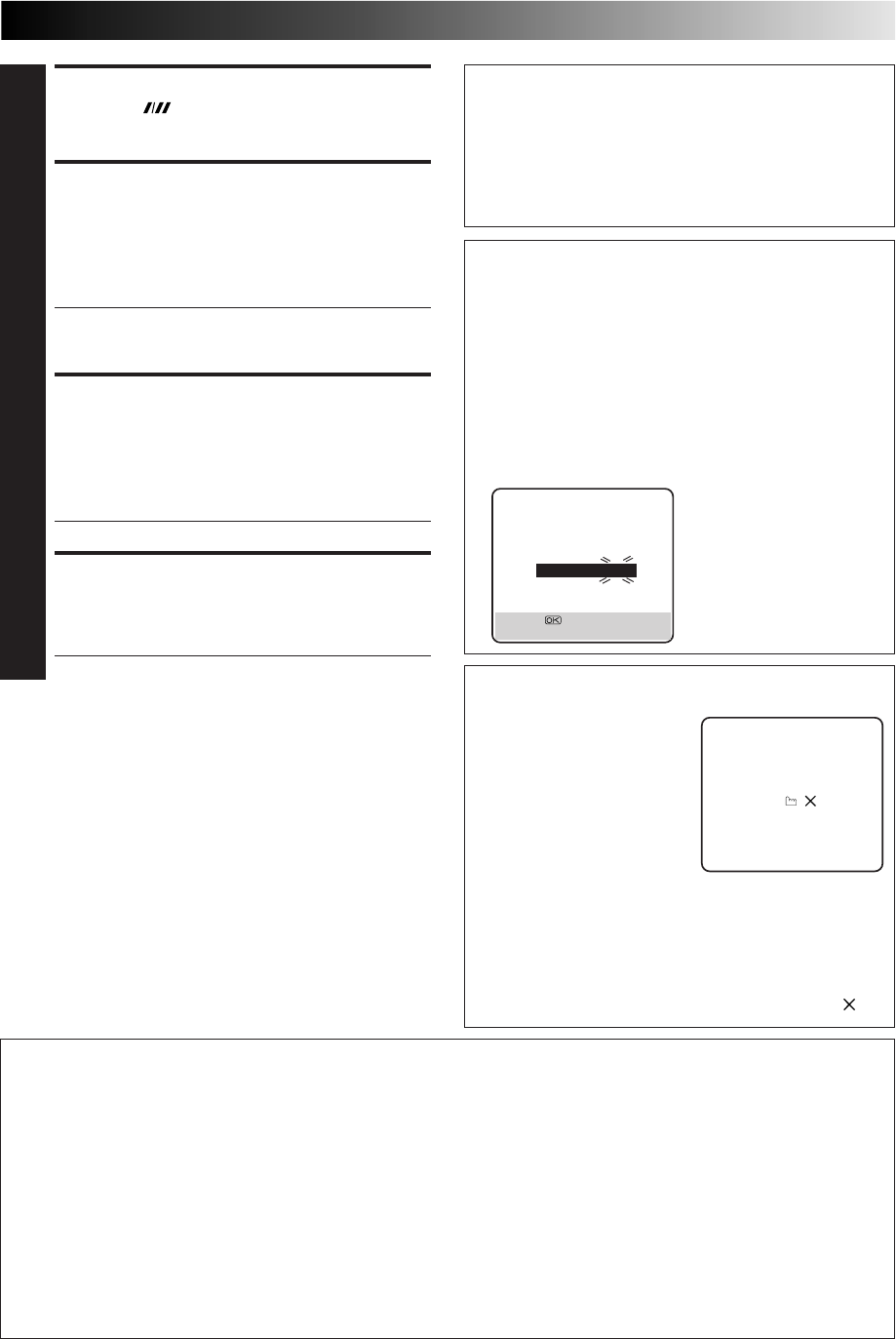
ATTENTION
Regarding Guide Program Number Set
"GUIDE PROG SET" appears after performing step 3 if the
Guide Program number for the PlusCode number you
entered has not been set.
●If you want to set the Guide Program number for the
satellite broadcast station, press the NUMBER key "0" to
change "TV PROG" to "SAT". Press %fi to input the preset
position number on which your recorder or satellite
receiver receives that station, then press OK or
#
to set
the Guide Program Number. The VIDEO Plus+ Program
screen appears.
(Ex.) To timer-record a BBC2
programme with the VIDEO
Plus+ system.
* If your recorder receives
BBC2 on the preset position
2, press OK or
#
after
entering "2" using %fi
buttons.
Satellite Receiver Users
To timer-record a satellite broadcast using the VIDEO Plus+
system:
1Perform "Satellite Receiver Control Setting" (Z pg. 12).
2Perform steps 1 – 7. In step 3, the display panel shows
"L2" for the preset position. In step 5, you cannot set
PDC to ON.
3Leave the satellite receiver's power on.
Now available from some TV stations, PDC (Programme Delivery Control) is a service designed to assure safe, accurate timer
recording. With this system, special code signals are transmitted together with the audio/video signals. These code signals
control your video recorder and have precedence over the advertised times which you may have preset into the timer. This
means that your recorder will start and stop recording when the preset TV programmes actually start and end — even if the
broadcast time of a preset TV programme is changed from what has been advertised. PDC is currently available nationally on
BBC1, BBC2, Ch.4 and Ch.5, except from a few small relay transmitters. Ch.3 operates a PDC service in some areas. All
channels intend to offer this service in due course. Check your TV programme listing guide for latest information. If the channel
you intend to record does not offer a PDC service your recorder will not start recording if PDC has been selected. Be sure to set
PDC to "OFF" if PDC is not available on your selected channel (Z step 5 above).
NOTES:
●
PDC recording is also possible when a satellite receiver or a cable system is connected to AV2 (L-2) IN/DECODER on your
recorder.
●
PDC recording is also possible via the AV1 (L-1) IN/OUT connector.
PDC Recording
Timer Warning
– WARNING–
TIMER RECORDING
TO START SOON
[ ]
If you have programmed your
recorder to timer-record a
programme or a series of
programmes, a warning
appears on the screen to tell
you that the recording is due
to start in 5 minutes.
NOTES:
●
The warning only appears if you’re not in the Timer
mode at the time.
●
If this recorder is being used as the player for tape
dubbing, the warning screen will be recorded on the
tape in the other video recorder.
The warning blinks for the entire 5 minutes leading up to
the start of timer recording. To clear the display, press .
GUIDE PROG SET
GUIDE PROG TV PROG
2 – –
[5∞] = [0]:SAT
[PROG] : EXIT
20
?
– –:– –
123
465
789
0
2
4
1
3
OK
WEEKLY
7
9
DAILY
6
Express Timer
Programming
BASIC OPERATIONS (cont.)
If you don’t know the PlusCode number for the programme you
wish to record, use the following procedure to set your recorder
to timer-record the programme.
START+/–
2,3
4
PROG
1,9
ACCESS VIDEO PLUS+
SCREEN
1
Press PROG.
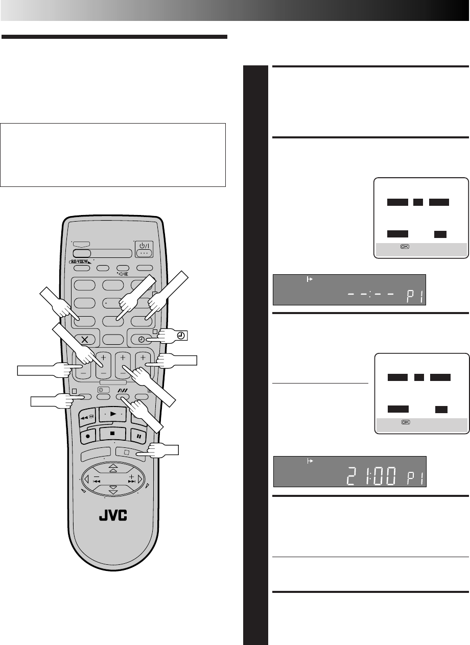
ACCESS PROGRAMME
SCREEN
2
Press START +/–. (If you’re
just starting out, “P1”
appears.)
The front display panel looks like this:
ENTER PROGRAMME
START TIME
3
Press START +/– to enter
the time you want
recording to start.
●Press and hold START
+/– to move in 30-
minute increments, or
press and release
repeatedly to move 1
minute at a time.
The front display panel looks like this:
ENTER PROGRAMME STOP
TIME
4
Press STOP +/– to enter the time you want recording to
stop.
●Press and hold STOP +/– to move in 30-minute
increments, or press and release repeatedly to move 1
minute at a time.
ENTER PROGRAMME DATE
5
Press DATE +/– to enter the date on which you wish to
record. (The current date first appears on screen. The
date you enter will appear in its place.)
Before performing Express Timer Programming:
●Make sure that the recorder's built-in clock is set
properly.
●Insert a cassette with the safety tab in place. The recorder
will come on automatically.
●Turn on the TV and select the VIDEO channel (or AV mode).
STOP+/–
DATE+/–
5
8
PDC
10
SP/LP
– P1 –
START STOP
– –:– – =– –:– –
SP VPS/PDC OFF
DATE TV PROG
– –.– – – –
[+/–] = [0]:SAT
[PROG] : EXIT
– P1 –
START STOP
21:00 =– –:– –
SP VPS/PDC OFF
DATE TV PROG
– –.– – – –
[+/–] = [0]:SAT
[PROG] : EXIT
SP
SP
PR+/–
21
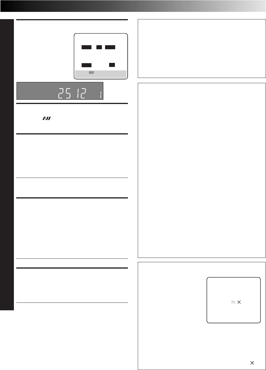
ENTER PRESET POSITION
6
Press PR +/– to enter the
preset position corre-
sponding to the broadcast-
ing station you wish to
record.
SET TAPE SPEED
7
Press SP/LP ( ) to set the tape speed.
SET PDC MODE
8
Press PDC to select "ON" or "OFF".
If "VPS/PDC ON" is displayed on the screen or "VPS/
PDC" is lit on the display panel, PDC is set to ON.
If "VPS/PDC OFF" is displayed on the screen or "VPS/
PDC" is not lit on the display panel, PDC is set to OFF.
Z "PDC Recording" in the right column.
●VPS (Video Programme System) recording is not
currently available in the U.K. and not possible with
this recorder.
RETURN TO NORMAL
SCREEN
9
After confirming all information is correct, press PROG
or OK. "PROGRAM COMPLETED" appears on the
screen for about 5 seconds, then normal screen
appears. If the timer programme is overlapped with
another one that was already set, "PROGRAM
OVERLAPPED" appears on screen and "Err" appears on
the front display panel. (Z pg. 23)
●Repeat steps 1 – 9 for each additional programme.
ENGAGE RECORDER’S
TIMER MODE
10
Press ‰ (TIMER). The recorder turns off automatically
and ‰ appears on the display panel.
●To disengage the timer, press ‰ (TIMER) again.
To Timer-Record Weekly Or Daily Serials . . .
. . . anytime during steps 2 through 9, press WEEKLY (NUMBER
key “9”) for weekly serials or DAILY (NUMBER key “8”) for
daily serials (Monday – Friday). Either "WEEKLY" or "DAILY"
appears on the screen. Pressing the button again makes the
corresponding indication disappear.
Satellite Receiver Users
To timer-record a satellite broadcast using Express Timer
Programming:
1Perform "Satellite Receiver Control Setting" (Z pg. 12).
2Perform steps 1 – 10. In step 6, press the NUMBER key
"0" to change "TV PROG" to "SAT". The display panel
shows "L2" for the preset position. Then press PR +/– to
enter the preset position for the satellite broadcast. In
step 8, you cannot set PDC to ON.
3Leave the satellite receiver's power on.
NOTE:
You can programme this recorder to timer-record as many as 8
programmes. If you try to programme the recorder to record a
ninth, "PROGRAM FULL" appears on screen and "FULL" appears
on the front display panel. To record the extra programme, you
must first cancel any unnecessary programmes (
Z
pg. 22).
Now available from some TV stations, PDC (Programme
Delivery Control) is a service designed to assure safe,
accurate timer recording. With this system, special code
signals are transmitted together with the audio/video
signals. These code signals control your video recorder and
have precedence over the advertised times which you may
have preset into the timer. This means that your recorder
will start and stop recording when the preset TV
programmes actually start and end — even if the broadcast
time of a preset TV programme is changed from what has
been advertised. PDC is currently available nationally on
BBC1, BBC2, Ch.4 and Ch.5, except from a few small relay
transmitters. Ch.3 operates a PDC service in some areas.
All channels intend to offer this service in due course.
Check your TV programme listing guide for latest informa-
tion. If the channel you intend to record does not offer a
PDC service your recorder will not start recording if PDC
has been selected. Be sure to set PDC to "OFF" if PDC is
not available on your selected channel.
(Z step 8 in the left column).
NOTES:
●
Set the start time (PDC time) exactly as advertised in the
TV listing. A different time than advertised will result in
no recording.
●
PDC recording is also possible when a satellite receiver or
a cable system is connected to AV2 (L-2) IN/DECODER on
your recorder.
●
PDC recording is also possible via the AV1 (L-1) IN/OUT
connector.
PDC Recording
Timer Warning
If you have programmed your
recorder to timer-record a
programme or a series of
programmes, a warning
appears on the screen to tell
you that the recording is due
to start in 5 minutes.
NOTES:
●
The warning only appears if you’re not in the Timer
mode at the time.
●
If this recorder is being used as the player for tape
dubbing, the warning screen will be recorded on the
tape in the other video recorder.
The warning blinks for the entire 5 minutes leading up to
the start of timer recording. To clear the display, press .
– P1 –
START STOP
21:00 =22:00
SP VPS/PDC OFF
DATE TV PROG
25.12 1
BBC 1
[+/–] = [0]:SAT
[PROG] : EXIT
SP
– WARNING–
TIMER RECORDING
TO START SOON
[ ]
22
?
– –:– –
123
465
789
0
2
4
1
3
BASIC OPERATIONS (cont.)
Check, Cancel And Replace
Programmes
DISENGAGE TIMER MODE
1
Press ‰, then press .
ACCESS PROGRAMME CHECK
SCREEN/DISPLAY
2
Press .
ACCESS PROGRAMME SCREEN/
DISPLAY
3
Press again to check
more information. Each
time you press , the
next programme's
information appears.
●The display panel shows the programme start time.
Pressing OK changes the display to the programme
stop time, then the date and the preset position.
To cancel or replace a programme...
CANCEL OR REPLACE A
PROGRAMME
4
Press to cancel a programme. To replace a
programme, press the appropriate button: START+/–,
STOP+/–, DATE+/–, PR+/–, SP/LP ( ), PDC.
●You can change "TV PROG" to "SAT" for the preset
position by pressing the NUMBER key "0".
RETURN TO NORMAL SCREEN/
DISPLAY
5
Press as many times as necessary. If there are still
some programmes to be recorded, go on to step 6.
RETURN TO TIMER MODE
6
Press ‰.
NOTE:
You can also check the programmes on the display panel even
if the recorder's power is off (unless the recorder is in the Power
Save mode
Z
pg. 41) or the recorder is in the Timer mode;
however, it is not possible to cancel or replace the programmes.
OK
SP/LP
PDC
START+/–
DATE+/–
– P1 –
START STOP
8:00 =10:00
SP VPS/PDC OFF
DATE TV PROG
24.12 3
ITV
[] : NEXT
START STOP CH DATE
18
:
00 10
:
00 3 24
.
12
210
:
00 10
:
45 2 25
.
12
311
:
30 13
:
00 1 25
.
12
4
5
6
7
8
[] : NEXT
SP
STOP+/–
PR+/–
23
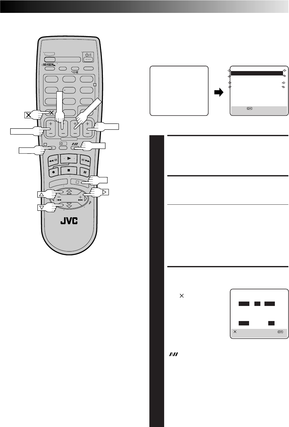
When programmes overlap
each other
If "PROGRAM OVERLAPPED" appears, you have another
programme overlapping the programme you have just made.
The Program Check screen appears and conflicting programmes
will start blinking.
EX. Programme 1 (you have just made) and
Programme 4 overlap each other.
CONFIRM OVERLAPPING
PROGRAMMES
1
Overlapping programmes blink on the screen.
SELECT PROGRAMME TO
MODIFY
2
Press %fi, then press OK or
#
.
●You can only select one of the overlapping
programmes.
NOTE:
If you do not mind this overlap, press PROG to finish
the timer programme setting. The programme with the
lower programme number will be recorded and the
other one will not be recorded correctly. Without doing
anything for about 1 minutes, the recorder will finish
the timer programming.
CANCEL OR CHANGE
PROGRAMME SETTING
3
To cancel a programme,
press when the Program
screen you do not want is
shown. "PROGRAM
COMPLETED" appears on
the screen for about 5
seconds, then normal
screen appears.
To change a programme,
press the appropriate
button: START+/–, STOP+/–, DATE +/–, PR +/–, SP/LP
() and/or PDC when the Program screen on which
you want to make changes is shown, then press OK.
"PROGRAM COMPLETED" appears on the screen for
about 5 seconds, then normal screen appears.
NOTE:
If the overlap is not yet solved or another overlap
occurs with the timer programme setting made last after
making correction on a programme, the conflicting
programmes will be shown on the Program Check
screen again. Repeat the above steps again until the
overlap is solved.
START STOP CH DATE
18
:
00 10
:
00 3 24
.
12
210
:
00 10
:
45 2 25
.
12
311
:
30 13
:
00 1 25
.
12
4
5
6
7
8
[] : NEXT
PROGRAM OVERLAPPED
START STOP CH DATE
18
:
00 10
:
00 3 24
.
12
210
:
00 10
:
45 2 25
.
12
311
:
30 13
:
00 1 25
.
12
49
:
00 10
:
00 92 DAILY
5
6
7
8
[5∞] =
[PROG] : EXIT
?
– –:– –
123
465
789
0
2
4
1
3
PROG
– P1 –
START STOP
8:00 =10:00
SP VPS/PDC OFF
DATE TV PROG
24.12 3
ITV
[] : DELETE [+/–] =
[PROG] : EXIT
PR+/–
SP/LP
OK
DATE+/–
STOP+/–
START+/–
24
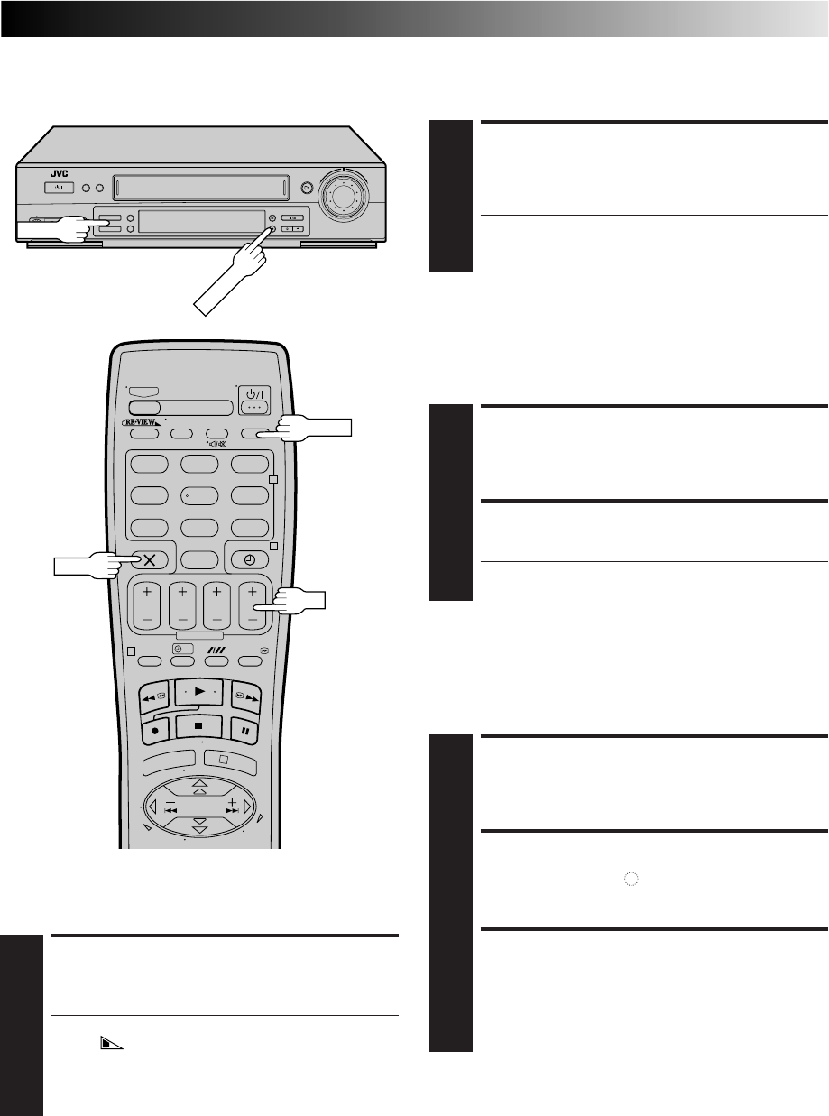
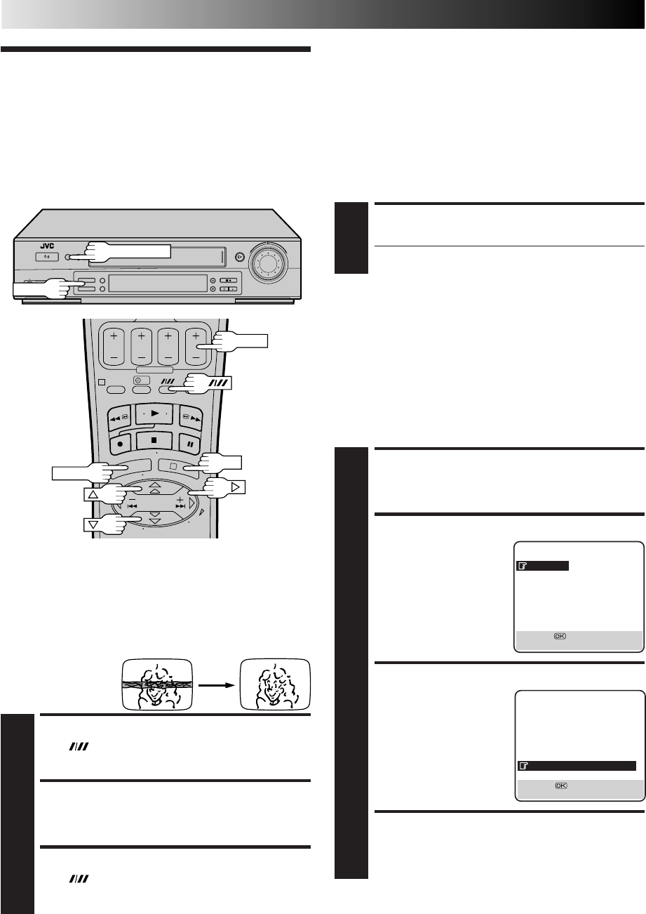
Your video recorder is equipped with automatic tracking control. For
most tapes this will automatically adjust the tracking to suit the
particular tape you are playing. In some circumstances it may be
necessary to make manual tracking adjustments. This is usually only
associated with old or worn tapes or recordings made on old or worn
recorders. If the automatic tracking control fails to operate correctly
you will see noise bars across the picture as shown on the left below.
To correct this you can
override the automatic
control and adjust the
tracking manually by
pressing the PR buttons.
OVERRIDE AUTOMATIC TRACKING
1
Press on the remote to engage manual tracking.
ADJUST TRACKING MANUALLY
2
Press PR + or – to adjust tracking.
RETURN TO AUTOMATIC TRACKING
3
Press on the remote to re-engage automatic
tracking.
NOTE:
When a new tape is inserted, the recorder returns to the
automatic tracking mode automatically.
Playback
Picture
Adjustment
?
1
3
Manual Tracking
PR+/–
PR+/–
ADVANCED OPERATIONS
DIGITAL TBC/NR
Digital 3R
Digital 3R picture system applies edge correction to the luminance
signal to enhance detail.
ACCESS MAIN MENU SCREEN
1
Press MENU.
ACCESS MODE SET SCREEN
2
Move the highlight bar
(arrow) to "MODE SET" by
pressing %fi, then press
OK or
#
.
SELECT DIGITAL 3R SET MODE
3
Move the highlight bar
(arrow) to "DIGITAL 3R"
by pressing %fi, then press
OK or
#
to set to "ON".
RETURN TO NORMAL SCREEN
4
Press MENU.
NOTES:
●
Normally it is recommendable to keep "DIGITAL 3R" set to "ON".
●
Depending on the type of tape being used, picture quality
may sometimes be better with "DIGITAL 3R" set to "OFF".
●
If you use the recorder as the source player for editing, be
sure to set "DIGITAL 3R" to "OFF" before starting.
MAIN MENU
MODE SET
AUTO CH SET
MANUAL CH SET
OUTPUT/INPUT SET
INITIAL SET
[5∞] =
[MENU] : EXIT
Digital TBC/NR
Your video recorder is equipped with a Digital TBC (Time Base
Corrector) that removes jitter from fluctuating video signals to
deliver a stable picture even with old tapes and rental cassettes.
The on/off of Digital 3-DNR (Noise Reduction) which cuts noise
and enables clear picture reproduction is also linked to this
function.
* The default setting is "ON".
We recommend that you use the Digital TBC feature when...
... playing back a tape recorded on a camcorder.
... playing back a tape repeatedly used.
... using this video recorder as the player for editing.
ACTIVATE DIGITAL TBC/NR
1
Press DIGITAL TBC/NR so that the button lights up.
●To turn off DIGITAL TBC/NR, press DIGITAL TBC/NR
again so that the light goes off.
NOTES:
●
If you play back a tape recorded under poor TV reception
condition, there may be cases where the picture becomes
more stable with Digital TBC/NR set to off.
●
When Digital TBC/NR is set to on, if you play back a tape
where certain types of signals are recorded (using a PC or
some character generators), the playback picture may be
distorted. If this is the case, turn off Digital TBC/NR.
MODE SET
B. E. S. T. ON
PICTURE CONTROL AUTO
AUTO TIMER OFF
O. S. D. ON
DIRECT REC ON
AUTO SP=LP TIMER OFF
DIGITAL 3R ON
NEXT PAGE
[5∞] =
[MENU] : EXIT
OK
MENU
25
?
– –:– –
123
465
789
0
2
4
1
3
Selecting The
Sound You
Want
AUDIO
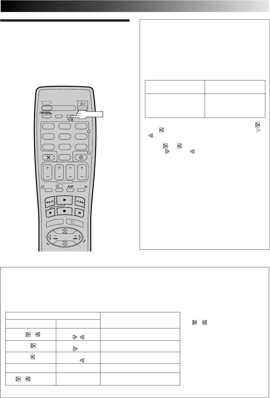
Soundtrack Selection
Your video recorder is capable of recording three soundtracks (HI-FI L, HI-FI R and NORM) and will play back the one you
select.
During Playback
Pressing AUDIO on the remote control changes the soundtrack being played back as follows:
TRACK
Recorder's Front Panel On-Screen Display USE
+ HI FI For Hi-Fi stereo tapes
LR
HI FI For main audio of Bilingual tapes
L
HI FI For sub audio of Bilingual tapes
R
NORM NORM For audio-dubbed tapes
+ + NORM HI FI For audio-dubbed tapes
NORM
NOTES:
●
" + " should normally be
selected. In this mode, Hi-Fi stereo
tapes are played back in stereo, and
the normal audio track is played
back automatically for tapes with
only normal audio.
●
For instructions on recording
NICAM stereo and bilingual
programmes, see above.
●
Bilingual programmes are not
currently broadcast in the U.K.
●
"O.S.D." must be set to "ON" or the
on-screen displays will not appear
(
Z
pg. 40).
Receiving NICAM Stereo
And Bilingual Programmes
Your recorder is equipped with a Digital stereo sound
decoder (NICAM), making reception of stereo and
bilingual broadcasts possible.
When the recorder is tuned to a different station, the type
of broadcast being received will be displayed on the TV
screen for a few seconds.
●To listen to a stereo programme, press AUDIO until " "
and " " appear on the front display panel or "HI FI L
R" appears on the screen.
●To listen to a bilingual programme, press AUDIO until
either " " or " " appears on the front display panel or
"HI FI L " or "HI FI R" appears on the screen (as
required).
●To listen to the Standard (regular monaural) audio while
receiving a NICAM broadcast, press AUDIO until
"NORM" appears on the front display panel or on the
screen.
NOTES:
●
The NICAM audio programme will be recorded on the
Hi-Fi audio track, and the Standard audio programme on
the normal audio track.
●
If the quality of stereo sound being received is poor, the
broadcast will be received in monaural with better quality.
●
Before playing back a programme recorded in stereo, or a
bilingual programme, refer to "Soundtrack Selection" (See
below).
●
"O.S.D." must be set to "ON" or the on-screen displays
will not appear (
Z
pg. 40).
Type of Broadcast On-screen Display
Being Received
Regular Monaural (none)
NICAM Stereo ST NICAM
NICAM Bilingual BIL. NICAM
NICAM Monaural NICAM
26
ADVANCED OPERATIONS (cont.)
?
– –:– –
123
465
789
0
2
4
1
3
Index Search
Your recorder automatically marks
index codes at the beginning of
each recording. This function gives
you quick access to any one of 9
index codes in either direction.
NOTE:
Before starting, make sure the
recorder is in the Stop mode.
ACTIVATE INDEX SEARCH
1
Press
@
or
#
(™ or £). “™ 1” or “£ 1” is
displayed on screen and search begins in the corre-
sponding direction.
●To access index codes 2 through 9, press
@
or
#
repeatedly until the correct index number is dis-
played.
Ex.: To locate the beginning of B from the current
position, press
@
twice.
To locate the beginning of D from the current
position, press
#
once.
●When the specified index code is located, playback
begins automatically.
Current position
Index number
AB C D E F
–2 –1 1 2 3
£ 2
Looking For
The Scene
You Want
SKIP OVER UNWANTED
SECTIONS
1
Press 30 SEC 1 to 4 times during playback. Each press
initiates a 30-second period of fast-motion playback.
Normal playback resumes automatically.
NOTE:
To return to normal playback during a Skip Search, press PLAY.
Skip Search
30 SEC
Instant ReView
Simply by pressing a single button, the recorder power comes
on, rewinds, and begins playback of the last timer-recorded
programme. If you have several programmes recorded, you can
easily access any of them.
NOTE:
Before starting, make sure that the recorder is off and that the
Timer mode is disengaged.
ACTIVATE INSTANT
REVIEW
1
Press REVIEW. The recorder power comes on and the
recorder searches for the index code indicating the start
of the last timer-recorded programme. Once it’s found,
playback begins automatically.
●The front display panel tells you how many
programmes have been timer-recorded. If you have,
for example, 3 programmes, “REVIEW” and "3"
appear and blink. To watch the first of the 3
programmes, press REVIEW three times. The recorder
searches and begins playback automatically. You can
access a programme as far as 9 index codes away
from the current tape position.
NOTES:
●
Instant ReView is not possible while the recorder is in the
Timer mode.
●
The number of recorded programmes will not be displayed on
the front display panel after Auto Satellite Prog recording
(
Z
pg. 30).
REVIEW
OK
MENU
RECORD
PLAY
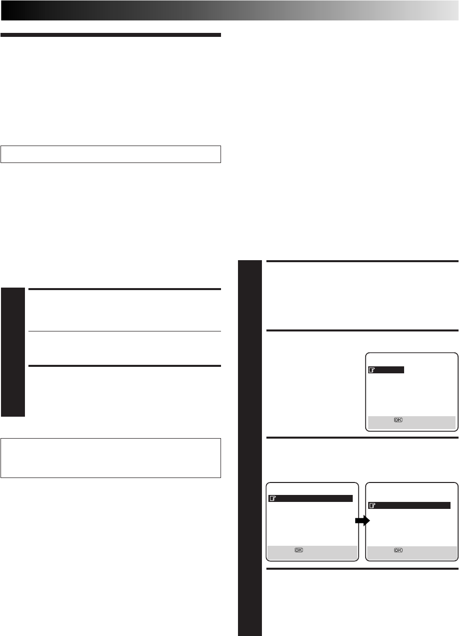
27
Super VHS (S-VHS),
S-VHS ET and VHS
Your recorder can record in S-VHS, S-VHS ET or VHS.
To record in S-VHS:
Perform the steps 1 – 4 below to set "S-VHS" to "ON".
Then, insert a cassette marked "S-VHS", the S-VHS indicator will
light on the display panel.
The S-VHS recording mode will be selected.
To record in S-VHS ET on a VHS cassette:
See "Super VHS ET (S-VHS ET)" in the left column.
To record in VHS:
Insert a cassette marked "VHS".
If the S-VHS ET button on the recorder is lit and the S-VHS ET
mode is activated, press S-VHS ET. The button's light goes off.
The VHS recording mode will be automatically selected
regardless of the S-VHS mode setting.
To record in VHS on an S-VHS cassette:
Insert the cassette marked "S-VHS", the S-VHS indicator will
light on the display panel.
Then, perform the steps 1 – 4 below to set the "S-VHS" to "OFF";
the S-VHS indicator will go out.
The VHS recording mode will be selected.
ACCESS MAIN MENU
SCREEN
1
Press MENU.
ACCESS MODE SET SCREEN
2
Move the highlight bar
(pointer) to "MODE SET"
by pressing %fi, then press
OK or
#
.
SELECT S-VHS MODE
3
Move the highlight (pointer) to "S-VHS" by pressing
%fi, then press OK or
#
to select "ON" or "OFF".
RETURN TO NORMAL
SCREEN
4
Press MENU.
NOTE:
When playing back a tape that has been recorded in S-VHS or
S-VHS ET, the S-VHS indicator lights on the display panel
regardless of the "S-VHS" mode setting.
Recording
According To
Tape Type
MAIN MENU
MODE SET
AUTO CH SET
MANUAL CH SET
OUTPUT/INPUT SET
INITIAL SET
[5∞] =
[MENU] : EXIT
Turn on the TV and select the VIDEO channel (or AV mode).
MODE SET
B. E. S. T. ON
PICTURE CONTROL AUTO
AUTO TIMER OFF
O. S. D. ON
DIRECT REC ON
AUTO SP=LP TIMER OFF
DIGITAL 3R ON
NEXT PAGE
[5∞] =
[MENU] : EXIT
PREVIOUS PAGE
POWER SAVE OFF
S-VHS ON
[5∞] =
[MENU] : EXIT
Super VHS ET (S-VHS ET)
— Recording on VHS tapes
with S-VHS quality
This function allows you to record in SP mode on VHS tapes with
S-VHS picture quality. Tapes recorded using this function can be
played back on a recorder equipped with the S-VHS ET function.
●You can activate this function only before you start recording
on a VHS tape.
●Before recording, make sure that "B.E.S.T." is set to "ON".
(Z pg. 28)
ENGAGE S-VHS ET MODE
1
Press S-VHS ET on the recorder's front panel. The
S-VHS ET button lights up.
●The S-VHS indicator lights up on the front display panel.
●To disengage the S-VHS ET mode, press S-VHS ET.
The button's light goes off.
START RECORDING
2
Press and hold RECORD and press PLAY on the remote
control, or press RECORD on the recorder.
NOTES:
●
Use of high grade tapes is essential for S-VHS ET record-
ings. On some tapes, picture quality will not improve
even if the S-VHS ET function is used. Check the record-
ing quality before you start important recordings.
●
You cannot activate the S-VHS ET function ...
... while recording is in progress.
... while timer-recording or Instant Timer Recording
(
Z
pg. 17) is in progress.
... while B.E.S.T. (
Z
pg. 28) is in progress.
●
S-VHS ET does not work ...
... with S-VHS tapes.
... with recordings in LP mode.
●
To keep the highest quality recording and playback pictures
over a long period of time, S-VHS recording on S-VHS tapes
is recommended.
●
You can play back S-VHS ET recordings on most S-VHS
recorders and on VHS recorders equipped with SQPB (S-VHS
QUASI PLAYBACK) function. (Notice: some recorders are not
compatible with this function.)
●
On some tapes noise may appear when playing back a tape
recorded with this function. (If playback picture becomes
blurred or interrupted, use a cleaning cassette.)
●
In the high-speed search, still, slow-motion or frame-by-frame
playback modes (
Z
pg. 15), noise may appear. If these
modes are used frequently on a tape recorded with the S-VHS
ET function, the tape may be damaged and the picture may
be deteriorated.
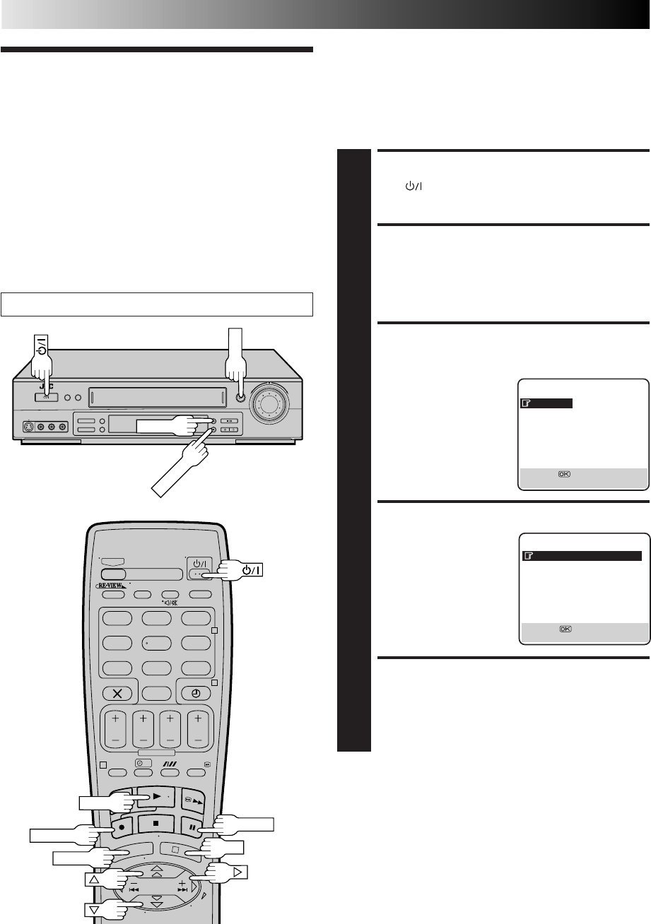
28
?
– –:– –
123
465
789
0
2
4
1
3
ADVANCED OPERATIONS (cont.)
Playback/
Recording
According To
Tape Charac-
teristics
The B.E.S.T. (Biconditional Equalised Signal Tracking) system
checks the condition of the tape in use during recording and
playback, and compensates to provide the highest-possible
recording and playback pictures. The default setting for both
recording and playback is “ON”.
B.E.S.T. Picture System
TURN ON THE RECORDER
1
Press .
ACCESS MAIN MENU
SCREEN
2
Press MENU.
ACCESS MODE SET
SCREEN
3
Press %fi to move the
highlight bar (pointer) to
"MODE SET", then press
OK or
#
.
SELECT B.E.S.T. MODE
4
Press %fi to move the
highlight bar (pointer) to
"B.E.S.T.", then press OK
or
#
to set to "ON" or
"OFF".
RETURN TO NORMAL
SCREEN
5
Press MENU.
PLAY
PAUSE
PLAY
OK
MENU
RECORD
RECORD
Turn on the TV and select the VIDEO channel (or AV mode).
MAIN MENU
MODE SET
AUTO CH SET
MANUAL CH SET
OUTPUT/INPUT SET
INITIAL SET
[5∞] =
[MENU] : EXIT
MODE SET
B. E. S. T. ON
PICTURE CONTROL AUTO
AUTO TIMER OFF
O. S. D. ON
DIRECT REC ON
AUTO SP=LP TIMER OFF
DIGITAL 3R ON
NEXT PAGE
[5∞] =
[MENU] : EXIT
PAUSE
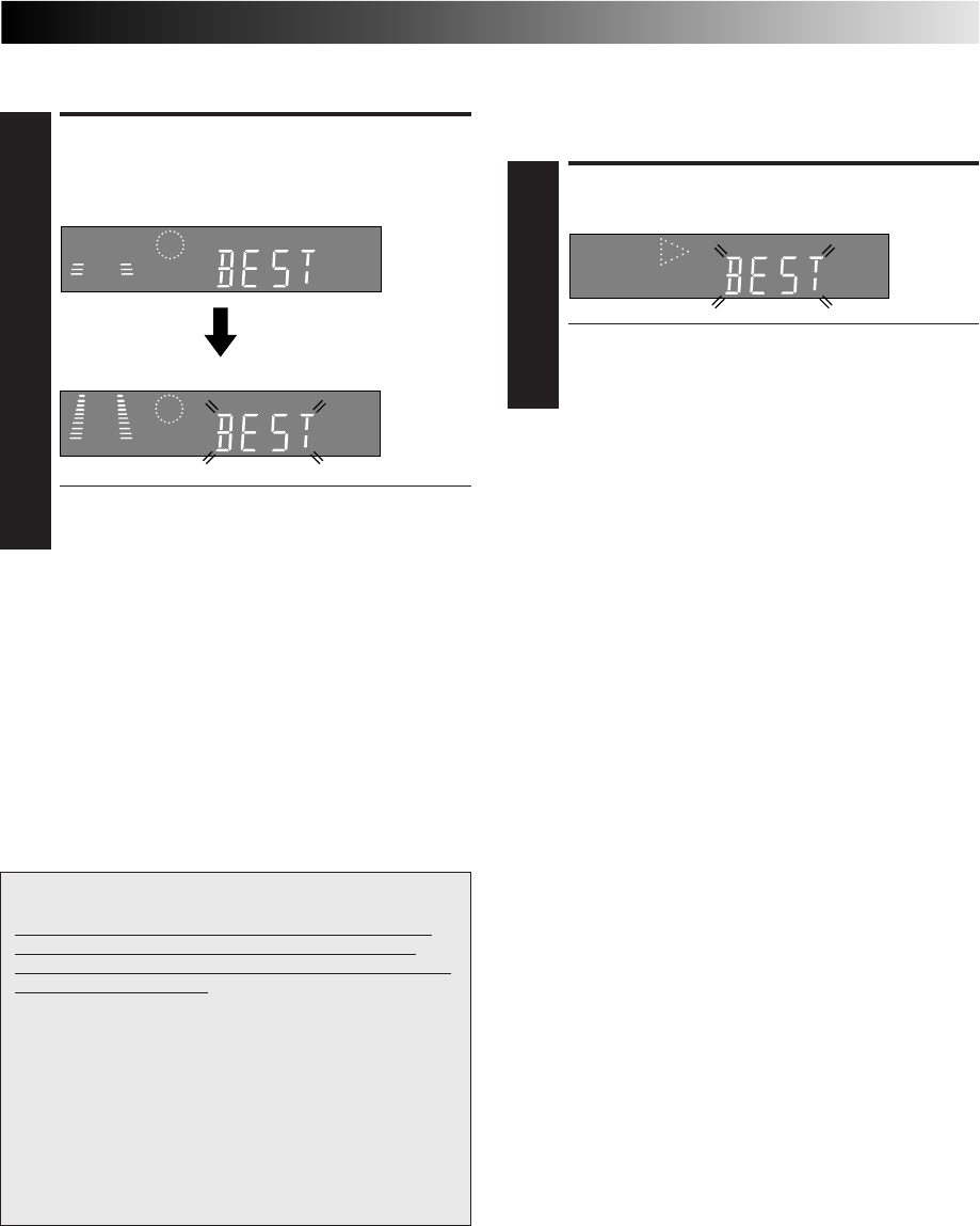
29
Recording
START RECORDING
1
Press and hold RECORD and press PLAY on the remote,
or press RECORD on the recorder.
DURING B.E.S.T.
B.E.S.T. COMPLETE
●The recorder spends approximately 7 seconds
assessing the condition of the tape, then begins
recording.
NOTES:
●
The B.E.S.T. system works for both SP and LP modes only after
a tape has been inserted and the Record mode is first
initiated. It does not work during recording.
●
The B.E.S.T. system does not work while Auto Satellite Prog
recording is in progress (
Z
pg. 30).
●
In the case of timer recording, the B.E.S.T. system works
before recording is initiated.
●
Once the cassette is ejected, the B.E.S.T. data is cancelled.
The next time the cassette is used for recording, B.E.S.T. is re-
performed.
●
Pressing the recorder's RECORD button while "BEST" is
displayed does not start Instant Timer Recording (
Z
pg. 17).
Playback
The recorder assesses the quality of the tape once you initiate
playback.
START PLAYBACK
1
Press PLAY.
●The recorder adjusts the playback picture quality
based on the quality of the tape in use.
●B.E.S.T. is active during Auto Tracking. “BEST”
appears blinking on the recorder’s display panel.
NOTES:
●
When watching a tape recorded with “B.E.S.T.” set to “ON”,
it is recommended that you leave B.E.S.T. on during playback
as well.
●
When watching a rental tape or one recorded on another
video recorder, or when using this recorder as the player for
editing, set B.E.S.T. to your preference by performing steps 1
through 5 on page 28.
●
"BEST" only appears at the beginning of automatic tracking.
Even though it doesn't appear after that, the B.E.S.T. function
is operative.
ATTENTION
Since the B.E.S.T. system works before recording actually
starts, there is a delay of approximately 7 seconds after
RECORD and PLAY on the remote are pressed, or RECORD
on the recorder is pressed. To make sure you record the
desired scene or programme in its entirety, first perform the
following steps:
1) Press and hold PAUSE and press RECORD to engage the
RECORD PAUSE mode.
●
The recorder then automatically checks the condition
of the tape and, after approximately 7 seconds, re-
enters RECORD PAUSE.
2) Press PLAY when you are ready to start recording.
●
If you want to bypass the B.E.S.T. system and begin
recording immediately, set “B.E.S.T.” to “OFF” in step
4 on page 28.
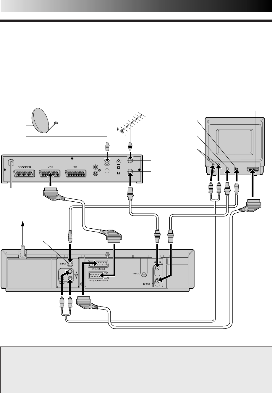
30
This facility allows you to record automatically a satellite programme which is timer-programmed on your external satellite receiver.
Connect a satellite receiver to the recorder's AV2 (L-2) IN/DECODER connector and programme the timer on the satellite receiver;
the recorder starts recording when the signals input from the satellite receiver to the AV2 (L-2) IN/DECODER connector, and when
there is no input signals the recorder stops recording and the power shuts off.
Automatic Satellite
Programme Recording
NOTE:
Refer to the instructions supplied with your satellite receiver.
Mains outlet
TV Aerial cable Aerial
connector
Satellite Receiver Unit
Satellite Cable
Outdoor Unit Aerial Back of TV
21-pin AV input
connector (SCART)
RF OUT
ANT. IN
Back of Recorder
ADVANCED OPERATIONS (cont.)
IMPORTANT
When you set "L-2 SELECT" to "SAT" (Z pg. 36), it is possible to view a satellite broadcast with the TV set to its AV mode even if
the recorder is turned off. When the recorder is in Stop mode or recording, press TV/VCR on the remote control to turn off the
VCR indicator on the display panel.
●If you turn on the recorder when the satellite receiver's power is off, nothing appears on the TV screen. In this case, turn on
the satellite receiver, or set the TV to its TV mode, or press TV/VCR on the remote control to set the recorder to the video
mode.
S-VIDEO IN
connector
AUDIO IN
connector
S OUT
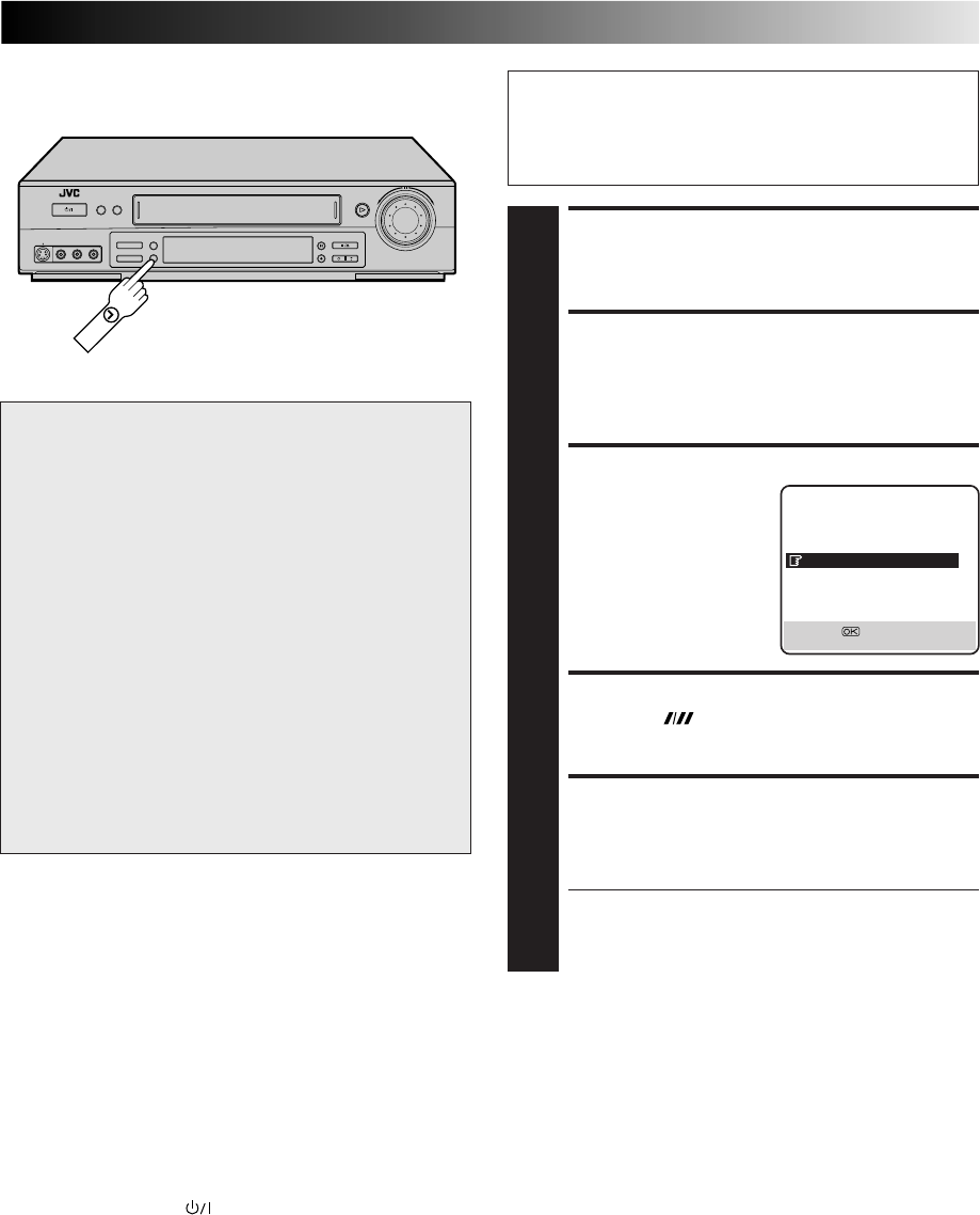
31
ATTENTION
●Be sure not to turn on the satellite receiver before the
programme is executed; otherwise, the recorder will start
recording when the satellite receiver's power is turned on.
●If you have connected another appliance other than a
satellite receiver to the AV2 (L-2) IN/DECODER
connector, be sure not to engage the Auto Satellite Prog
Rec mode; otherwise, the recorder will start recording
when the connected appliance's power is turned on.
●Auto Satellite Prog recording and timer-recording cannot
be done at the same time.
●When you press and hold the recorder's SAT‰ button to
engage the Auto Satellite Prog Rec mode, if the SAT‰
button does not light but instead blinks quickly even
though your satellite receiver's power is off, Auto Satellite
Prog Recording will not work properly with that satellite
receiver*.
If this is the case, perform "Express Timer Programming"
(Z pg. 20) to timer-record a satellite programme.
* Some satellite receivers output signals even if the power is off.
Auto Satellite Prog Recording is not possible with those satellite
receivers.
Before performing the following steps:
●Make sure the satellite receiver is connected to the
recorder's AV2 (L-2) IN/DECODER connector. (Z pg. 30)
●Programme the timer on the satellite receiver.
●Insert a cassette with the safety tab in place.
ACCESS MAIN MENU SCREEN
1
Press MENU.
ACCESS OUTPUT/INPUT SET
SCREEN
2
Move the highlight bar (pointer) to "OUTPUT/INPUT
SET" by pressing %fi, then press OK or
#
.
SELECT L-2 SELECT MODE
3
Move the highlight bar
(pointer) to "L-2 SELECT",
by pressing %fi, then press
OK or
#
to set to "SAT" or
"A/V". Then press MENU.
SET TAPE SPEED
4
Press SP/LP ( ) to set the tape speed.
ENGAGE AUTO SATELLITE PROG
REC MODE
5
Press and hold SAT‰ for about 2 seconds. The button
lights up and the recorder turns off automatically.
●To disengage the Auto Satellite Prog Rec mode, press
SAT‰. The light goes off.
●If the recorder's power is off, it is not possible to
engage the Auto Satellite Prog Rec mode.
NOTES:
●
Auto Satellite Prog recording is possible with the AV2 (L-2) IN/DECODER connector only.
●
When the Auto Satellite Prog Rec mode is engaged or the recorder's power is turned off after Auto Satellite Prog recording is
finished, the recorder will not enter the Timer mode even though "AUTO TIMER" is set to "ON".
●
After Auto Satellite Prog recording, the number of recorded programmes will not be displayed on the front display panel for the
Instant ReView function (
Z
pg. 26).
●
For timer programming of the satellite receiver, refer to the instruction manual of the satellite receiver.
●
Auto Satellite Prog recording is not possible if your satellite receiver does not have a timer.
●
The SAT
‰
button blinks while Auto Satellite Prog recording is in progress.
●
Pressing the recorder's button while Auto Satellite Prog recording is in progress turns off the recorder's power and disengages
the Auto Satellite Prog Rec mode.
●
If there is more than one satellite programme you wish to record with Auto Satellite Prog Recording, it is not possible to set a
different tape speed for each; the tape speed selected in step 4 will apply to all the programmes for Auto Satellite Prog recording.
●
The B.E.S.T. system (
Z
pg. 28) does not work while Auto Satellite Prog recording is in progress.
●
Just Clock (
Z
pg. 55) does not work when the Auto Satellite Prog Rec mode is engaged.
●
Depending on the type of satellite receiver, the recorder may not record a short portion at the beginning of the programme or may
record slightly longer than the actual length of the programme.
●
If you engage the Auto Satellite Prog Rec mode when the satellite receiver's power is on, the recorder will not start Auto Satellite
Prog recording even though the SAT
‰
button blinks. When the satellite receiver shuts off once and is turned back on again, the
recorder starts recording.
●
You can also record a programme from your cable system in the same way if the system has a timer and is connected to the
recorder's AV2 (L-2) IN/DECODER connector.
SAT
OUTPUT/INPUT SET
L-1 OUTPUT VIDEO
L-1 INPUT VIDEO
L-2 SELECT SAT
L-2 INPUT VIDEO
[5∞] =
[MENU] : EXIT
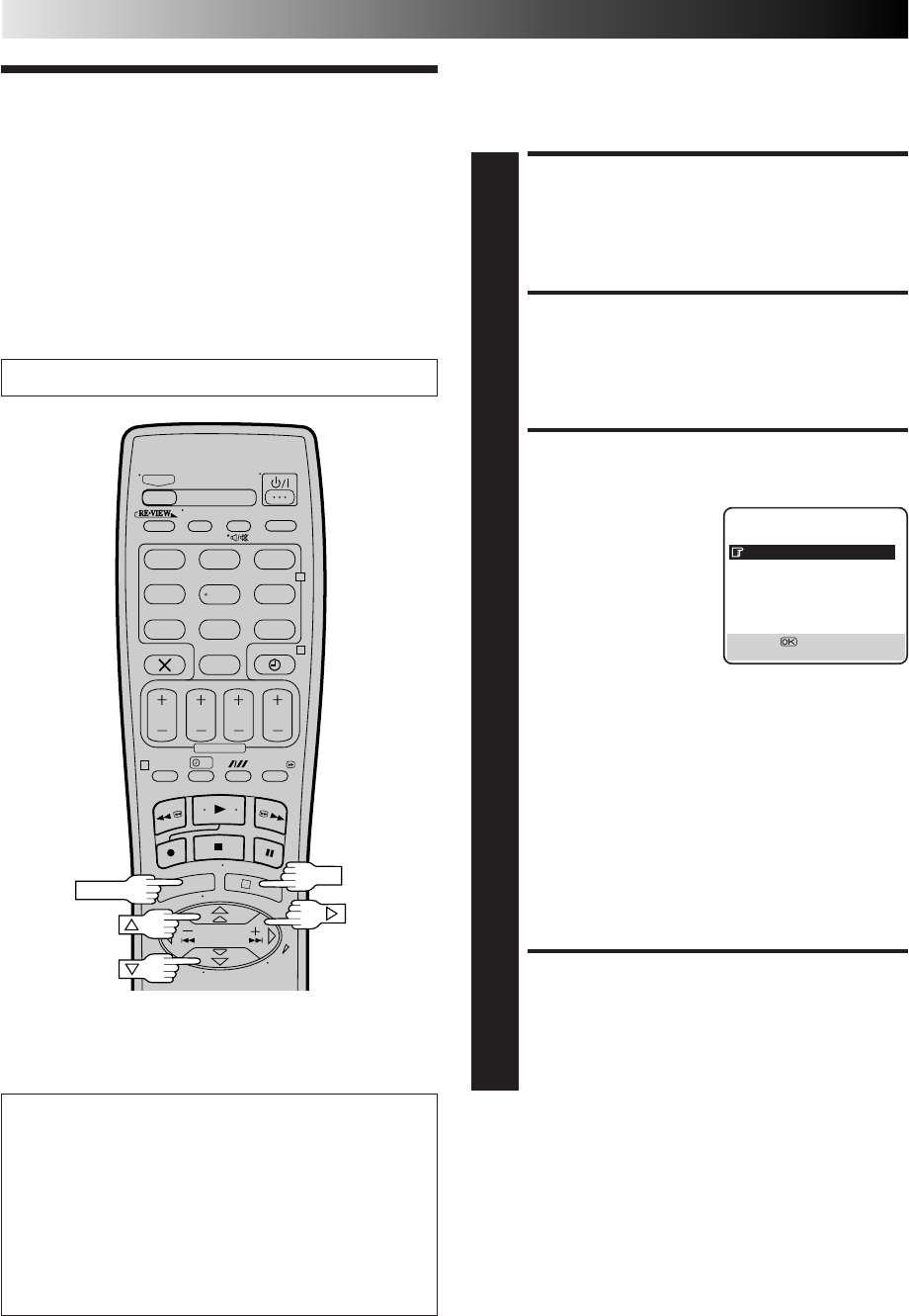
32
ADVANCED OPERATIONS (cont.)
Minimizing
Picture
Degradation
While Editing
Turn on the TV and select the VIDEO channel (or AV mode).
?
– –:– –
123
465
789
0
2
4
1
3
OK
MENU
Picture Control
This feature helps you to adjust the playback picture quality
according to your preference. *The default setting is "AUTO."
ACCESS MAIN MENU
SCREEN
1
Press MENU.
ACCESS MODE SET
SCREEN
2
Move the highlighted bar (pointer) to "MODE SET" by
pressing %fi, then press OK or
#
.
SELECT PICTURE
CONTROL SET MODE
3
Move the highlighted bar
(pointer) to "PICTURE
CONTROL" by pressing
%fi, then press OK or
#
to
select the desired mode.
AUTO: Provides
optimised picture
benefits of B.E.S.T.
Picture System.
Normally select
"AUTO".
EDIT: Minimizes picture degradation during editing
(recording and playback).
SOFT: Reduces image coarseness when viewing
overplayed tapes containing a lot of noise.
SHARP: Clearer, sharper-edged picture when viewing
images with lots of flat, same-coloured surfaces
such as cartoons.
NOTES:
●
When you select "EDIT", "SOFT" or "SHARP", the
selected mode will not change until you select again.
●
When you select "EDIT" to dub tapes, be sure to
select "AUTO" after you finish dubbing the tapes.
RETURN TO NORMAL
SCREEN
4
Press MENU.
NOTES:
●
When "B.E.S.T." is "OFF", "PICTURE CONTROL" switches
automatically from "AUTO" to "NORM".
●
Select "EDIT" when you are dubbing tapes. Refer to page 33
or 34.
MODE SET
B. E. S. T. ON
PICTURE CONTROL AUTO
AUTO TIMER OFF
O. S. D. ON
DIRECT REC ON
AUTO SP=LP TIMER OFF
DIGITAL 3R ON
NEXT PAGE
[5∞] =
[MENU] : EXIT
Advantages Of S-VHS
Video Recorders
You can edit from VHS to S-VHS, S-VHS to VHS, or, from
S-VHS to S-VHS.
●From VHS to S-VHS: Record VHS playback signals in the
S-VHS mode. Although the picture quality is inherently
limited by that of the original, the edited tape has better
picture quality than those made by VHS-to-VHS editing.
●From S-VHS to VHS: Because the picture quality of the
source material is very high, the edited tape has better
picture quality than those made by VHS-to-VHS editing.
●From S-VHS to S-VHS: All signals will be transferred with
minimum degradation.
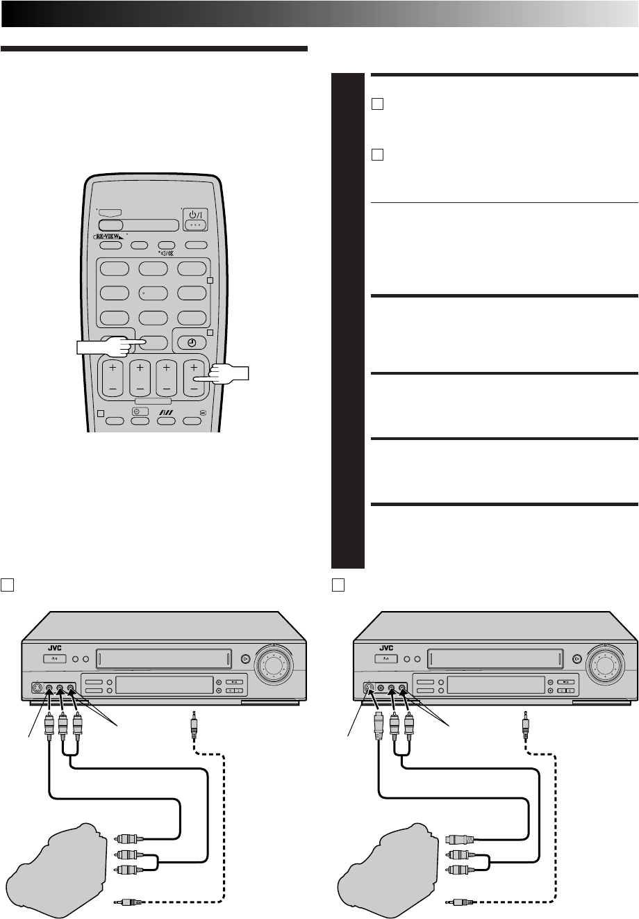
33
?
– –:– –
123
465
789
0
2
4
1
Edit From
A Camcorder
AUX
PR
You can use a camcorder as the source player and your video
recorder as the recorder.
MAKE CONNECTIONS
1
A
If the camcorder has no S-VIDEO output connector...
... connect the camcorder’s AUDIO/VIDEO OUT
connectors to the recorder’s front panel AUDIO/
VIDEO input connectors.
B
If the camcorder has an S-VIDEO output connector...
... connect the camcorder’s S-VIDEO OUT and
AUDIO OUT connectors to the recorder’s front
panel S-VIDEO and AUDIO input connectors.
●When using a monaural camcorder, connect its
AUDIO OUT connector to the AUDIO L input
connector on your recorder.
●When a Master Edit Control-equipped JVC camcorder
is used, the camcorder is capable of controlling the
recorder. Refer to the camcorder’s instruction manual
for operating procedure.
SET RECORDER’S INPUT MODE
2
Press AUX and/or PR to select "F-1" for the AUDIO/
VIDEO input connectors, or "S-1" for the AUDIO/
S-VIDEO input connectors, depending on the connec-
tors being used.
SET EDIT MODE
3
See "Picture Control" on page 32.
START CAMCORDER
4
Engage its Play mode.
START RECORDER
5
Engage its Record mode.
Mini-Plug Cable
(not provided)
(JVC camcorder
only)
VIDEO OUT
EDIT
Camcorder
VIDEO
input
Recorder
To rear panel PAUSE
connector
AUDIO OUT
Video Cable (not provided)
Player
AUDIO input
A If the camcorder has no S-VIDEO output connector...
Mini-Plug Cable
(not provided)
(JVC camcorder
only)
S-VIDEO OUT
EDIT
Camcorder
S-VIDEO
input
Recorder
To rear panel PAUSE
connector
AUDIO OUT
Audio Cable (not provided)
Player
B If the camcorder has an S-VIDEO output connector...
AUDIO input
S-Video Cable (not provided)
Audio Cable (not provided)
NOTES:
●
All necessary cables can be obtained from your dealer.
●
You can also use another video recorder as the player instead
of a camcorder.
●
When you select "EDIT" to dub tapes in step 3, be sure to
select "AUTO" (or "NORM" when "B.E.S.T." is set to "OFF")
after you finish dubbing the tapes.
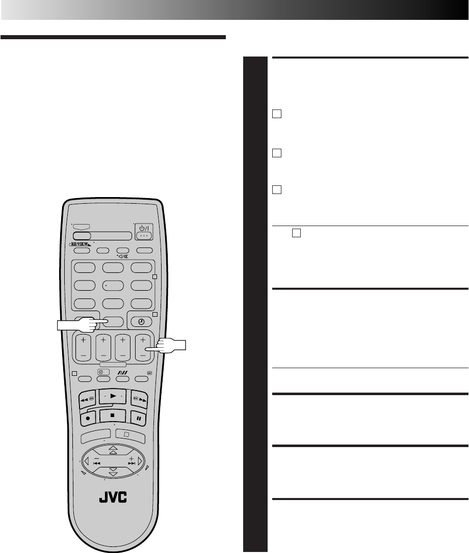
34
?
– –:– –
123
465
789
0
2
4
1
3
Edit To Or
From Another
Video
Recorder
You can use your video recorder as the source player or as the
recording deck.
MAKE CONNECTIONS
1
Connect the player’s 21-pin SCART connector to the
recorder’s 21-pin SCART connector as illustrated on
page 35.
A
When Using Your Video Recorder As The Source
Player ...
... connect its AV1 (L-1) IN/OUT connector to the
recording deck.
B
When Using Your Video Recorder As The Recording
Deck ...
... connect its AV2 (L-2) IN/DECODER or AV1 (L-1)
IN/OUT connector to the source player.
C
If Another Recorder Is Compatible With The Y/C
Signal ...
... connect your recorder
's
AV1 (L-1) IN/OUT
connector to another recorder.
With C connection ...
●When using your recorder as the recording deck, set
"L-1 INPUT" to "S-VIDEO" and "L-2 SELECT" to "A/V"
(Z pg. 36).
●When using your recorder as the source player, set
"L-1 OUTPUT" to "S-VIDEO" (Z pg. 36).
SET RECORDING DECK’S
INPUT MODE
2
Set to AUX. With this video recorder, press AUX and/or
PR to select “L-1” for the AV1 (L-1) IN/OUT connector,
or “L-2” for the AV2 (L-2) IN/DECODER connector,
depending on the connector being used.
● When using the AV2 (L-2) IN/DECODER connector,
set "L-2 SELECT" to the appropriate mode. (Z pg. 36)
SET EDIT MODE
3
See "Picture Control" on page 32.
START SOURCE PLAYER
4
Engage its Play mode.
START RECORDING DECK
5
Engage its Record mode.
PR
AUX
ADVANCED OPERATIONS (cont.)
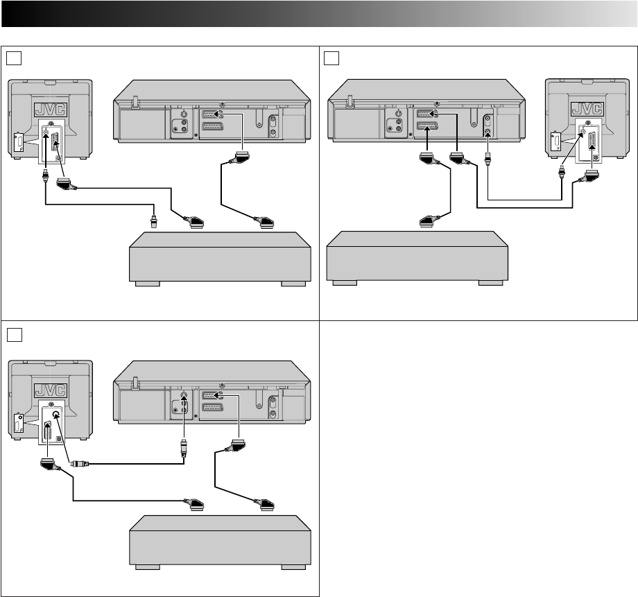
35
RF Cable
(provided)
21-pin SCART Cable
(not provided)
Player Your recorder Recorder Your recorderTV Receiver TV Receiver
RF Cable
(provided)
21-pin SCART Cable
(not provided)
VIDEO
CHAN-
NEL or
AV mode
VIDEO
CHANNEL
or AV mode
Another recorderAnother recorder
Recorder Player
A B
NOTES:
●
All necessary cables can be obtained from your dealer.
●
For Y/C signal input/output, be sure to use a 21-pin SCART cable that is compatible with the Y/C signal.
●
When you select "EDIT" to dub tapes in step 3, be sure to select "AUTO" (or "NORM" when "B.E.S.T." is set to "OFF") after you
finish dubbing the tapes.
●
When you use this recorder as the player for editing, be sure to set "O.S.D." to "OFF" before starting (
Z
pg. 40).
●
If you are using another recorder with S-Video and Audio input/output connectors, you can connect those connectors to this
recorder's S-VIDEO IN/S OUT and AUDIO IN/OUT connectors.
When Using Your Video Recorder As The Source Player ...
... connect its rear panel S OUT and AUDIO OUT connectors to the recording deck's S-Video and Audio input connectors.
When Using Your Video Recorder As The Recording Deck ...
... connect its front panel S-VIDEO and AUDIO input connectors to the source player's S-Video and Audio output connectors.
Then, set the recorder's input mode to "S-1".
Another recorder
Recorder
Player
Your recorder
TV Receiver
21-pin SCART Cable
(not provided)
S-Video Cable
(not provided)
C

36
ADVANCED OPERATIONS (cont.)
OUTPUT/INPUT SET
L-1 OUTPUT VIDEO
L-1 INPUT VIDEO
L-2 SELECT A/V
L-2 INPUT VIDEO
[5∞] =
[MENU] : EXIT
L-2 SELECT/INPUT Setting
The AV2 (L-2) IN/DECODER connector accepts either a composite signal (regular video signal) or a Y/C signal (a signal in which
the luminance and chrominance signals are separated). Set "L-2 SELECT" to the appropriate mode depending on the type of unit
connected to the rear panel AV2 (L-2) IN/DECODER connector of this recorder. Set "L-2 INPUT" to the appropriate mode
depending on the output signals of the connected unit.
1Press MENU to access the Main Menu screen.
2Press %fi to move the highlight bar (pointer) to "OUTPUT/INPUT SET", then press OK or
#
.
3Press %fi to move the highlight bar (pointer) to "L-2 SELECT" or "L-2 INPUT".
4For "L-2 SELECT"
Press OK or
#
to select "A/V", "DECODER" or "SAT".
a–A/V : To use this recorder as the recording deck with the player connected to the
AV2 (L-2) IN/DECODER connector, or to use the satellite receiver con-
nected to the AV2 (L-2) IN/DECODER connector.
b–DECODER : To use a decoder connected to the AV2 (L-2) IN/DECODER connector.
c–SAT : To view a satellite programme with the TV set while the recorder is turned
off. (Z pg. 30)
For "L-2 INPUT"
Press OK or
#
to select "VIDEO" or "S-VIDEO".
a–VIDEO : If a connected device's output is compatible only with regular video
signals, set to "VIDEO".
b–S-VIDEO : If a connected device's output is compatible with Y/C signals, set to
"S-VIDEO". This setting will let you take advantage of higher-quality S-VHS
pictures. (For connection, be sure to use a 21-pin SCART cable that is
compatible with the Y/C signal.)
5Press MENU to return to normal screen.
●If you have a satellite receiver or a decoder connected to the AV2 (L-2) IN/DECODER connector, be sure to set "L-2 SELECT"
back to appropriate mode after editing.
●If you're not connecting a satellite receiver or a decoder to the AV2 (L-2) IN/DECODER connector, leave "L-2 SELECT" set to
"A/V".
●The default setting is "A/V"; if the recorder's memory backup has expired due to a power cut or because the AC was removed
from the recorder, "A/V" will be automatically selected when the power is restored to the recorder. If you are using a satellite
receiver or a decoder, be sure to set "L-2 SELECT" back to appropriate mode.
●When "L-2 SELECT" is set to "SAT", "SAT" appears on screen or display panel instead of "L-2" or "L2".
●If "L-2 SELECT" is set to "DECODER", it is impossible to set "L-2 INPUT" to "S-VIDEO".
●If "L-1 OUTPUT" is set to "S-VIDEO", it is impossible to set "L-2 SELECT" to "DECODER".
L-1 OUTPUT/INPUT Setting
The AV1 (L-1) IN/OUT connector accepts and delivers either a composite signal (regular video signal) or a Y/C signal (a signal in
which the luminance and chrominance signals are separated). Set "L-1 OUTPUT" and "L-1 INPUT" to the appropriate mode
depending on the type of unit connected to the rear panel AV1 (L-1) IN/OUT connector of this recorder.
1Press MENU to access the Main Menu screen.
2Press %fi to move the highlight bar (pointer) to "OUTPUT/INPUT SET", then press OK or
#
.
3Press %fi to move the highlight bar (pointer) to "L-1 OUTPUT" or "L-1 INPUT".
4For "L-1 OUTPUT"
Press OK or
#
to select "VIDEO" or "S-VIDEO".
a–VIDEO : If a connected device's input is compatible only with regular video signals,
set to "VIDEO".
b–S-VIDEO : If a connected device's input is compatible with Y/C signals, set to
"S-VIDEO". This setting will let you take advantage of higher-quality
S-VHS pictures. (For connection, be sure to use a 21-pin SCART cable that
is compatible with the Y/C signal.)
For "L-1 INPUT"
Press OK or
#
to select "VIDEO" or "S-VIDEO".
a–VIDEO : If a connected device's output is compatible only with regular video
signals, set to "VIDEO".
b–S-VIDEO : If a connected device's output is compatible with Y/C signals, set to
"S-VIDEO". This setting will let you take advantage of higher-quality
S-VHS pictures. (For connection, be sure to use a 21-pin SCART cable that
is compatible with the Y/C signal.)
5Press MENU to return to normal screen.
●If "L-1 OUTPUT" is set to "S-VIDEO", it is impossible to set "L-1 INPUT" to "S-VIDEO".
●If "L-2 SELECT" is set to "DECODER", it is impossible to set "L-1 INPUT" to "S-VIDEO".
OUTPUT/INPUT SET
L-1 OUTPUT VIDEO
L-1 INPUT VIDEO
L-2 SELECT A/V
L-2 INPUT VIDEO
[5∞] =
[MENU] : EXIT
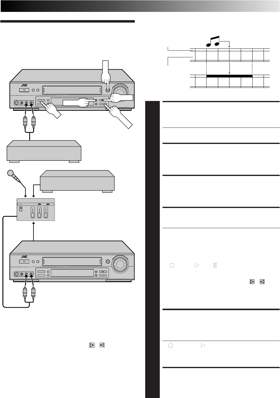
37
Audio dubbing replaces the normal audio sound of a previously
recorded tape with a new soundtrack.
Audio Dubbing
Original sound
AUDIO OUT
Audio mixer
MAKE CONNECTIONS
1
Connect an audio component to the AUDIO L + R
connectors on the recorder's front panel.
●When connecting monaural equipment, use only the
recorder's AUDIO L connector.
SET INPUT MODE
2
Press AUX and/or PR so that "F-1" or "S-1" appears in
place of a channel number.
LOCATE START POINT
3
Press PLAY to start playback of the tape in your
recorder, and press PAUSE when you find the point
where you want to start dubbing.
ENGAGE AUDIO DUBBING
4
Press A. DUB.
●It is possible to take the original sound recorded on
the tape in your recorder and mix it with other
sounds from a microphone, CD player etc. To
perform this audio dubbing with audio mixing,
connect as in the diagram on the left.
●Your recorder enters the Audio Dubbing Pause mode.
(" " blinks, " " and " " light up on the front display
panel.)
●To perform audio dubbing with audio mixing, press
AUDIO on the remote control to select "
+
(L+R)"
at this point.
* Audio dubbing with audio mixing is not possible if
you're using a monaural audio component, or if
you don't have an audio mixer.
START DUBBING
5
Engage the audio component's Play mode, then press
PLAY to start the tape in your recorder. Audio dubbing
begins at this point.
●"" blinks and " " is displayed on the front display
panel.
●To stop dubbing temporarily, press PAUSE. Press
PLAY to resume dubbing.
END AUDIO DUBBING
6
Press STOP to stop the tape in your recorder, and
engage the audio component's Stop mode.
Audio-dubbed tape
CD Player, etc.
Mixer
output
Pre-recorded tape
Normal audio track
Video/Hi-Fi audio
track
NOTES:
●
When monitoring the sound during Audio Dubbing, the
normal soundtrack is automatically selected. If you wish to
hear the mixed sound (Hi-Fi + Normal soundtracks), press
AUDIO on the remote control to select " + (L+R) +
NORM" (
Z
pg. 25).
●
Audio dubbing stops automatically when the counter reaches
"0:00:00", and the recorder enters the Play mode. Check the
counter reading before dubbing.
●
Audio dubbing is also possible using the rear panel AV1 (L-1) IN/
OUT or AV2 (L-2) IN/DECODER connector. When using these
connectors, make sure to select the correct input mode in step 2.
●
Audio dubbing cannot be performed on a cassette that has
had its record safety tab removed.
●
When playing back an audio-dubbed tape, press AUDIO on
the remote control to select the soundtrack you wish to hear
(
Z
pg. 25).
CD Player, etc.
PR
PLAY
PAUSE
A. DUB
STOP
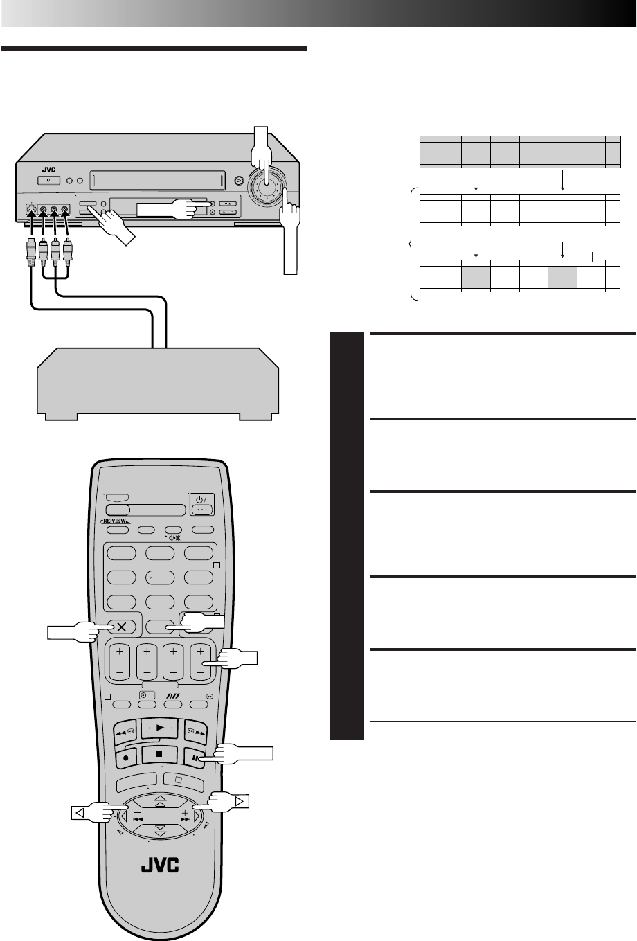
38
Insert editing replaces part of the recorded scene with new
material. Both the picture and Hi-Fi audio soundtrack are
replaced with new ones, while the normal audio soundtrack
remains unchanged. If you wish to change the normal audio
track as well, use the audio dubbing function simultaneously.
Use your video recorder as the recorder.
Insert Editing
ADVANCED OPERATIONS (cont.)
MAKE CONNECTIONS
1
Connect the player's VIDEO OUT or S-VIDEO OUT
and AUDIO OUT connectors to your recorder's VIDEO
or S-VIDEO and AUDIO input connectors on the front
panel.
SET INPUT MODE
2
Press AUX and/or PR so that "F-1" for the VIDEO/
AUDIO input connectors or "S-1" for S-VIDEO/AUDIO
input connectors appears in place of a channel number.
LOCATE END POINT
3
Load the recording cassette into your recorder, and play
it back to determine the edit-out point (the end of the
segment to be replaced) using the SHUTTLE ring or the
JOG dial or pressing
@ #
and PAUSE.
RESET THE COUNTER
4
Press 0000 to change the counter display to "0:00:00".
LOCATE START POINT
5
Determine the edit-in point (the beginning of the
segment to be replaced) using the SHUTTLE ring or the
JOG dial or pressing
@ #
and PAUSE.
●Be sure to engage the Still mode at the edit-in point.
Before insert editing
After insert editing
Source tape
Recorded tape Normal audio
track
Player
Audio/Video signal
Another recorder
Video/Hi-Fi
audio track
S-Video signal
Recorder Your recorder
?
– –:– –
123
465
789
0
2
4
1
3
0000
PR
PAUSE
AUX
PR
PAUSE
JOG
SHUTTLE
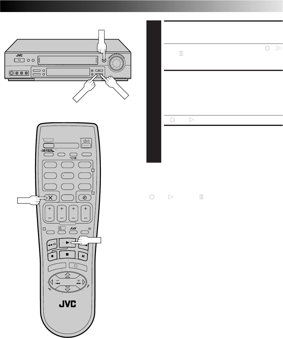
39
ENGAGE INSERT EDITING
6
Press INSERT.
●Your recorder enters the Insert-Pause mode. (" ", " "
and " " light up on the front display panel.)
●The TV screen changes from the still picture to the
input source you are going to record.
START EDITING
7
Load the source cassette and play back the segment
that is to be inserted. When you reach the start of the
section of the source tape that you wish to insert, press
PLAY to start the tape in your recorder; Insert Editing
begins at this point.
●"" and " " are displayed on the front display panel.
END INSERT EDITING
8
At counter "0:00:00", Insert Editing will stop automati-
cally while the tape continues running in the Play
mode. If you wish to stop Insert Editing before the
specified edit-out point, press 0000.
FOR AV INSERT EDITING
If you want to replace the picture, Hi-Fi audio soundtrack and
normal audio soundtrack all at the same time...
...
In step 6 above, after you press INSERT, press A. DUB also.
(" " and " " blink and " " lights up on the front display
panel.)
NOTES:
●
Suitable leads can be obtained from your dealer.
●
Insert editing is not possible with cassettes whose safety tab
has been removed.
●
When insert editing is performed on a tape that has been
recorded on another video recorder, the inserted portion may
appear distorted.
●
In insert editing, the recording speed (SP/LP) is determined by
the previous recording to be replaced. If the previous
recording's speed changes within a single edit, the inserted
picture will be distorted at the switching point.
●
A small portion of the recording which precedes an insert edit
may become erased.
●
Insert Editing is also possible using the rear panel AV1 (L-1) IN/
OUT or AV2 (L-2) IN/DECODER connector. When using these
connectors, make sure to select the correct input mode in step
2.
?
– –:– –
123
465
789
0
2
4
1
3
A. DUB
PLAY
INSERT
PLAY
0000
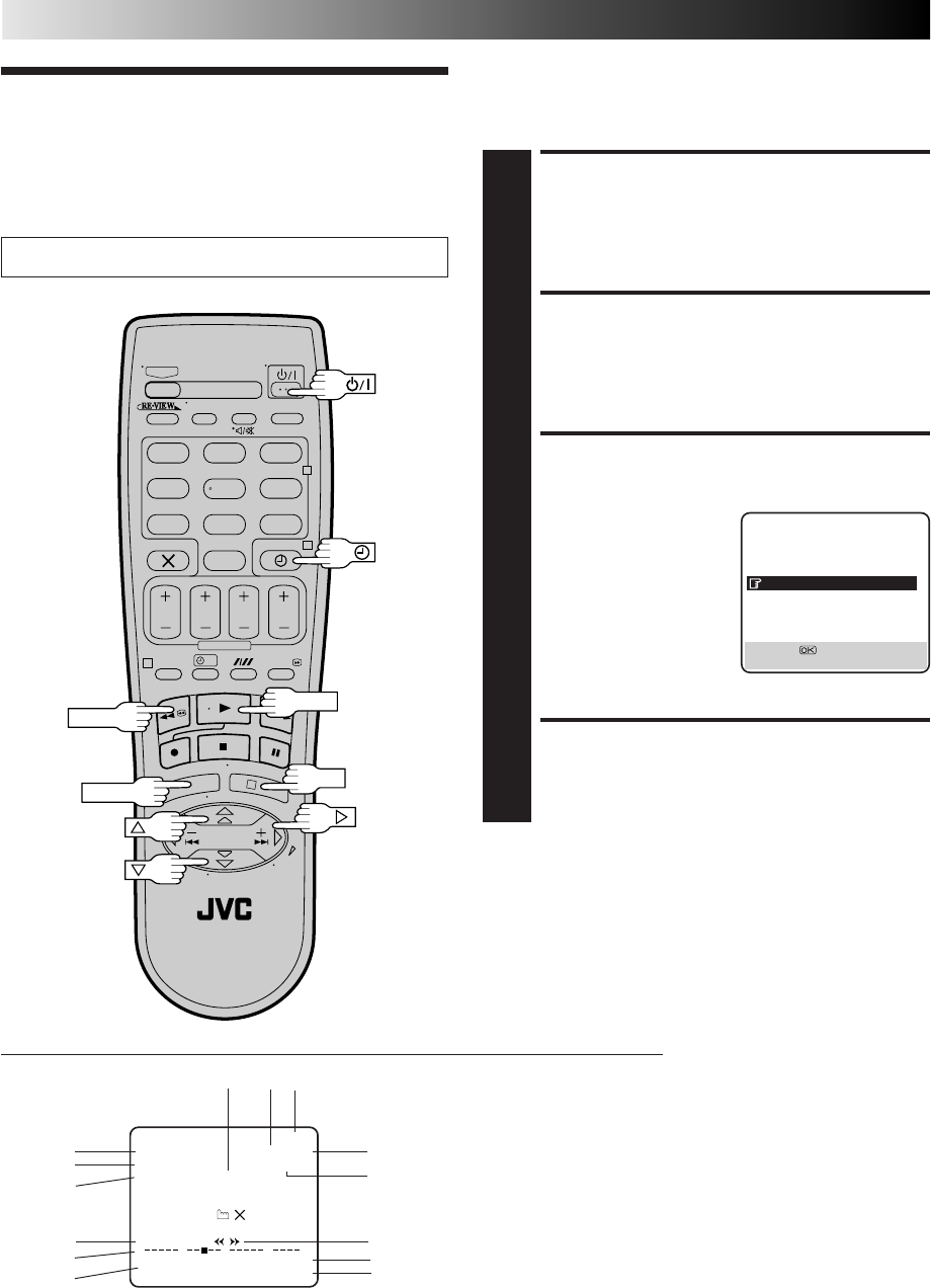
40
ADVANCED OPERATIONS (cont.)
?
– –:– –
123
465
789
0
2
4
1
3
OK
MENU
Turn on the TV and select the VIDEO channel (or AV mode).
On-Screen Display
NOTES:
●
When you use this recorder as the player for editing, be sure
to set "O.S.D." to "OFF" before starting.
●
During playback, the operation mode indicators may
sometimes be disturbed depending on the type of tape being
used.
You can choose whether or not to have various operational
indicators appear on screen, by setting this function ON or OFF.
ACCESS MAIN MENU
SCREEN
1
Press MENU.
ACCESS MODE SET
SCREEN
2
Move the highlight bar (pointer) to "MODE SET" by
pressing %fi, then press OK or
#
.
ENABLE/DISABLE
ON-SCREEN DISPLAY
3
The default setting is
“ON”, so if you want on-
screen displays, leave the
setting as it is and go to
step 4. If you don’t want
the displays to appear,
press %fi to move the
highlight bar (pointer) to
"O.S.D." and press OK
or
#
to set “O.S.D.” to
“OFF”.
RETURN TO NORMAL
4
Press MENU.
Other
Functions
1– Operation mode indicators
2– Tape speed SP/LP/EP (EP is for NTSC playback only)
3– NTSC playback display (Z pg. 43)
4– Tape direction
5– Counter display
6– Tape remaining time indicator (Z pg. 17)
7– Audio mode display (Z pg. 25)
8– Tape position indicator (Z pg. 14)
9– Type of Broadcast (Z pg. 25)
10– Current day/month/year
11– Clock display
12– Channel position number and station name/Aux. indicator
(L-1, L-2, SAT*, F-1 or S-1)
* When "L-2 SELECT" is set to "SAT" (
Z
pg. 36), "SAT"
appears instead of "L-2".
13– Timer warning display (Z pg. 19, 21)
14– Cassette loaded mark
The superimposed indication on the TV screen tells you what the recorder is doing.
MODE SET
B. E. S. T. ON
PICTURE CONTROL AUTO
AUTO TIMER OFF
O. S. D. ON
DIRECT REC ON
AUTO SP=LP TIMER OFF
DIGITAL 3R ON
NEXT PAGE
[5∞] =
[MENU] : EXIT
q6
PR. 12 ABCD ]SP
21 : 00 NTSC=PAL
24. 12. 00 – WARNING–
TIMER RECORDING
TO START SOON
[ ]
ST
HI FI –1 : 23 : 45
NORM REMAIN 1 : 00
0+++
+
1
14
12
11
10
9
8
7
5
6
2
13
4
3
REW
PLAY
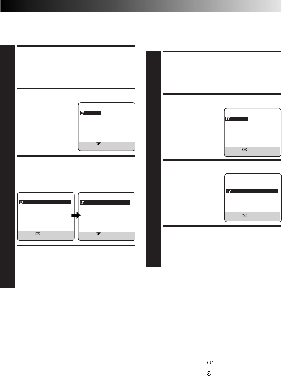
41
Power Save Mode
You can reduce the power consumption while the recorder is
turned off.
ACCESS MAIN MENU
SCREEN
1
Press MENU.
ACCESS MODE SET SCREEN
2
Press %fi to move the
highlight bar (pointer) to
"MODE SET", then press
OK or
#
.
SELECT POWER SAVE
MODE
3
Press %fi to move the highlight bar (pointer) to
"POWER SAVE", then press OK or
#
to set to "ON".
RETURN TO NORMAL
SCREEN
4
Press MENU.
NOTES:
●
During Power Save, the display panel will be turned off.
●
The Just Clock function (
Z
pg. 55) does not work while the
Power Save mode is engaged.
●
While the recorder is in the Power Save mode, the picture
may be distorted momentarily when you turn on/off the
recorder.
●
Power Save does not work when ...
... the recorder is in the Timer mode.
... the recorder's power is turned off after timer-recording (or
Instant Timer Recording).
... the Auto Satellite Prog Recording mode is engaged
(
Z
pg. 30).
... "L-2 SELECT" is set to "DECODER" or "SAT" (
Z
pg. 36).
MAIN MENU
MODE SET
AUTO CH SET
MANUAL CH SET
OUTPUT/INPUT SET
INITIAL SET
[5∞] =
[MENU] : EXIT
PREVIOUS PAGE
POWER SAVE ON
S-VHS ON
[5∞] =
[MENU] : EXIT
MODE SET
B. E. S. T. ON
PICTURE CONTROL AUTO
AUTO TIMER OFF
O. S. D. ON
DIRECT REC ON
AUTO SP=LP TIMER OFF
DIGITAL 3R ON
NEXT PAGE
[5∞] =
[MENU] : EXIT
Auto Timer
When "AUTO TIMER" is set to "ON" the timer is automatically
engaged when the recorder power is turned off and automati-
cally disengaged when the recorder is powered back on.
ACCESS MAIN MENU
SCREEN
1
Press MENU.
ACCESS MODE SET SCREEN
2
Press %fi to move the
highlight bar (pointer) to
"MODE SET", then press
OK or
#
.
SELECT MODE
3
Press %fi to move the
highlight bar (pointer) to
"AUTO TIMER", then press
OK or
#
to select either
"ON" or "OFF".
RETURN TO NORMAL
SCREEN
4
Press MENU.
NOTE:
For safety, when "AUTO TIMER" is set to "OFF", all other
recorder functions are disabled while the Timer mode is
engaged. To disengage the timer, press
‰
(TIMER).
MAIN MENU
MODE SET
AUTO CH SET
MANUAL CH SET
OUTPUT/INPUT SET
INITIAL SET
[5∞] =
[MENU] : EXIT
Next Function Memory
The Next Function Memory "tells" the recorder what to do
after rewinding. Before continuing, make sure the recorder
is in the Stop mode.
a– For Automatic Start Of Playback After Tape Rewind . . .
. . . press REW, then press PLAY within 2 seconds.
b– For Automatic Power Off After Tape Rewind . . .
. . . press REW, then press within 2 seconds.
c– For Automatic Timer Standby After Tape Rewind . . .
. . . press REW, then press (TIMER) within 2 seconds.
MODE SET
B. E. S. T. ON
PICTURE CONTROL AUTO
AUTO TIMER ON
O. S. D. ON
DIRECT REC ON
AUTO SP=LP TIMER OFF
DIGITAL 3R ON
NEXT PAGE
[5∞] =
[MENU] : EXIT
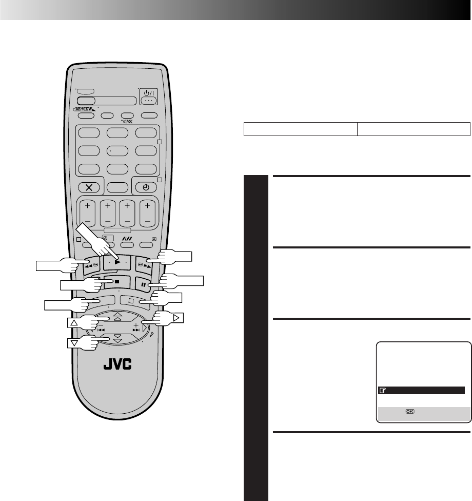
42
?
– –:– –
123
465
789
0
2
4
1
3
FF
REW
STOP
PAUSE
PLAY
ADVANCED OPERATIONS (cont.)
Auto SP→LP Timer
If, when timer-recording in SP mode, there is not enough tape to
record the entire programme, the recorder automatically
switches to LP mode to allow complete recording.
For Example . . .
Recording a programme of 210 minutes in length onto a 180-
minute tape
NOTES:
●
The Auto SP
→
LP Timer feature is not available during ITR
(Instant Timer Recording), and the feature will not work
properly with any tapes longer than E-180 or with some tapes
of shorter lengths.
●
If you have programmed the recorder to timer-record 2 or more
programmes, the second programme and those thereafter may
not fit on the tape if you set "AUTO SP
→
LP TIMER" to "ON". In
this case, make sure the mode is not engaged, then set the tape
speed manually during timer programming.
●
In order to ensure that the recording fits on the tape, this
feature may leave a short non-recorded section at the end of
the tape.
●
There may be some picture noise and sound disturbance at
the point on the tape where the recorder switches from SP to
LP mode.
●
If you perform timer recording with both PDC and the Auto
SP
→
LP Timer activated, and the programme goes beyond its
originally scheduled length, there may be times when the
programme cannot be recorded in its entirety.
Total 210 minutes
Approximately 150 minutes Approximately 60 minutes
SP mode LP mode
Make sure you set "AUTO SP→LP TIMER" to "ON" at the Mode
Set screen before the timer-recording starts.
ACCESS MAIN MENU
SCREEN
1
Press MENU.
ACCESS MODE SET
SCREEN
2
Press %fi to move the highlight bar (pointer) to "MODE
SET", then press OK or
#
.
SELECT MODE
3
Press %fi to move the
highlight bar (pointer) to
"AUTO SP→LP TIMER",
then press OK or
#
to select
"ON".
RETURN TO NORMAL
SCREEN
4
Press MENU.
MODE SET
B. E. S. T. ON
PICTURE CONTROL AUTO
AUTO TIMER OFF
O. S. D. ON
DIRECT REC ON
AUTO SP=LP TIMER ON
DIGITAL 3R ON
NEXT PAGE
[5∞] =
[MENU] : EXIT
OK
MENU
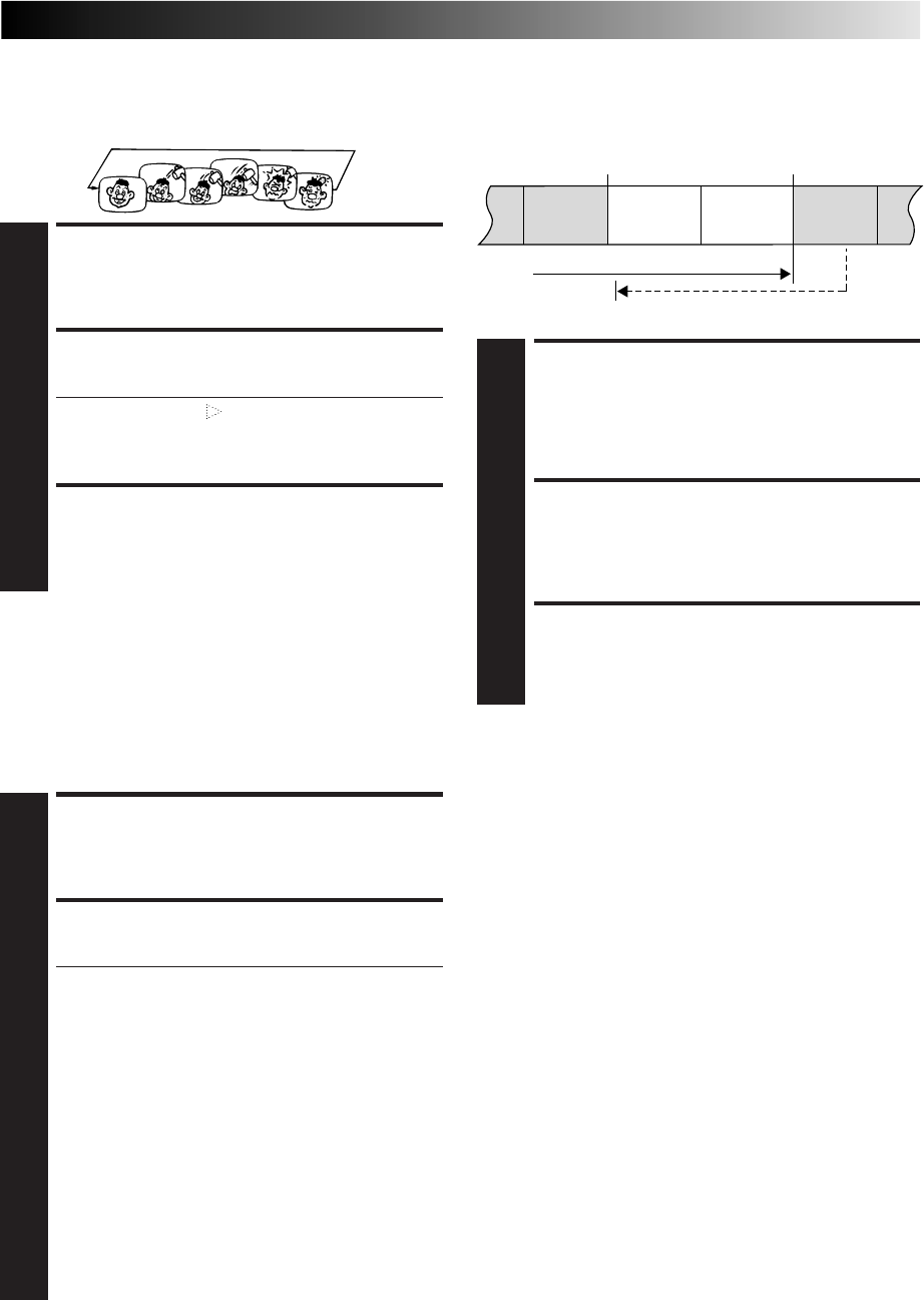
43
Repeat Playback
Your video recorder can automatically play back the whole tape
100 times repeatedly.
START PLAYBACK
1
Press PLAY.
ACTIVATE REPEAT PLAYBACK
2
Press PLAY and hold for over 5 seconds, then release.
●The Play indicator ( ) on the display panel blinks
slowly.
●The tape plays 100 times automatically, and then
stops.
STOP PLAYBACK
3
Press STOP at any time to stop playback.
NOTE:
Pressing PLAY, REW, FF or PAUSE also stops Repeat Playback.
NTSC Playback
Your video recorder is equipped with NTSC circuitry that can
play back NTSC tapes.
LOAD A CASSETTE
1
Insert a cassette recorded in NTSC.
START PLAYBACK
2
Press PLAY.
●"NTSC→PAL" appears on the screen for about 5
seconds.
●Some TVs shrink the picture vertically and place
black bars at the top and bottom of the screen. This is
not a malfunction on the part of either the video
recorder or the TV.
●The picture may roll up and down. This can be
corrected using the V-HOLD control found on some
TVs. (This cannot be corrected if the TV does not
have a V-HOLD control.)
●The counter and tape remaining time readings will be
incorrect.
●During search, still, or frame-by-frame playback, the
picture will be distorted, and there may be a loss of
colour.
●Depending on the type of TV, the top and bottom
portions of superimposed displays may be cut off
during NTSC playback.
Retake
You can cut out unnecessary parts of a TV programme while
you're recording it.
ENGAGE RECORD-PAUSE
MODE
1
Press PAUSE during recording.
LOCATE START POINT
2
Turn the JOG dial to the left or right (or hold down
REW or FF) and release it when you reach the point
where you want to resume recording.
* Your recorder returns to the Record-Pause mode.
RESUME RECORDING
3
Press PLAY when you wish to resume recording.
NOTE:
Retake function does not work during Direct Rec (
Z
pg. 11).
End of programme
Programme
Beginning of programme
Programme
Recorded part
Go back to end of programme to cut out
unnecessary part
Unnecessary
part Unnecessary
part
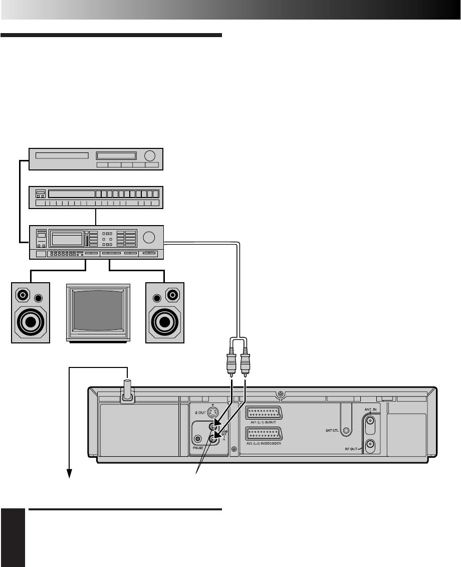
44
I
I
I
I
I
I
I
I
I
I
I
I
I
I
I
I
I
I
I
I
I
I
I
I
I
I
I
I
I
I
I
I
I
I
I
I
I
I
I
I
I
I
I
Connection To
A Stereo
System
These instructions enable you to connect your video recorder to
your Hi-Fi stereo system (if you have one) and listen to the
soundtrack through the stereo.
SYSTEM CONNECTIONS
MAKE CONNECTIONS
1
Connect the AUDIO OUT L and R connectors on your
video recorder to the AUX IN or TAPE MONITOR
terminals on your stereo system's receiver or amplifier.
NOTES:
●
When connecting your recorder's audio output connectors to
a stereo amplifier, make sure you connect L and R correctly.
●
If you can receive NICAM TV broadcasts in your area, this
recorder can record them independently of the TV set and
play them back through the connected stereo system.
●
When listening to sound through the connected stereo
system, turn the TV's volume down completely.
CAUTIONS:
●This recorder has a dynamic range of more than 80 dB with
regards to its Hi-Fi audio capability. It is recommended that
you check the maximum level if you are going to listen to the
Hi-Fi audio signals through a stereo amplifier. A sudden surge
in the input level to the speakers may damage them.
●Some speakers and televisions are specially shielded to
prevent television interference. If both are of the non-shielded
type, do not place the speakers adjacent to the TV set as this
can adversely affect the video playback picture.
AUX IN or TAPE MONITOR
Television
Back of Recorder
Speaker Speaker
CD Player
FM Tuner
Stereo Amplifier
Audio Cable
(not provided)
Mains outlet AUDIO OUT
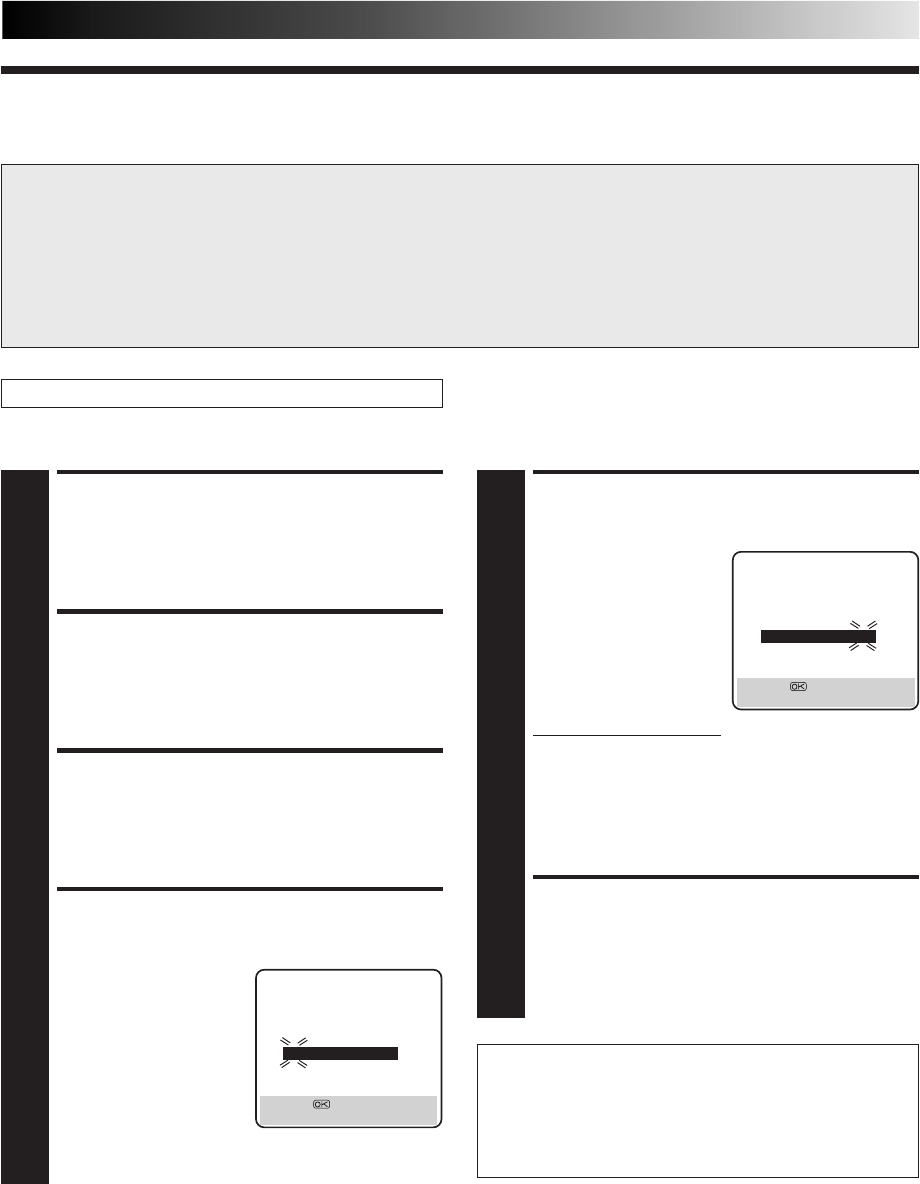
45
VIDEO Plus+ Setup
IMPORTANT
Normally, Auto Set Up (Z pg. 8), Preset Download (Z pg. 9) or Auto Channel Set (Z pg. 48) sets the Guide Program Numbers
automatically. You need to set the Guide Program Numbers manually only in the following cases.
●
When timer-programming with the VIDEO Plus+ system, the preset position, where the station you wish to record is received
on your recorder, is not selected or when you add a channel after Auto Set Up or Auto Channel Set has taken place.
— Set the Guide Program Number for that station manually.
●
When you wish to timer-record a satellite programme with the VIDEO Plus+ system.
— Set the Guide Program Numbers for all satellite broadcasts received on your satellite receiver.
Turn on the TV and select the VIDEO channel (or AV mode).
Guide Program Number Set
ACCESS MAIN MENU
SCREEN
1
Press MENU.
ACCESS INITIAL SET
SCREEN
2
Press %fi to move the highlight bar (pointer) to
"INITIAL SET", then press OK or
#
.
ACCESS GUIDE PROG SET
SCREEN
3
Press %fi to move the highlight bar (pointer) to "GUIDE
PROG SET", then press OK or
#
.
ENTER GUIDE PROG
NUMBER
4
Press %fi to enter the
Guide Program number for
the desired station as shown
in the TV listings. Then
press OK or
#
.
(Ex.) When inputting the
Guide Program
number 4 for CH4.
ENTER RECEIVING PRESET
POSITION NUMBER
5
Press the NUMBER key "0"
to select "TV PROG" or
"SAT". Then press %fi to
input the number of the
preset position on which
the Guide Program
number's broadcast is
received by the recorder or
the satellite receiver. Then
press OK or
#
.
●To timer-record a
satellite programme with
VIDEO Plus+, you need
to install the provided Satellite Controller and
perform the procedure described in "Satellite
Receiver Control Setting" (Z pg. 12).
● Repeat steps 4 and 5 as necessary.
RETURN TO NORMAL
SCREEN
6
Press MENU.
(Ex.) If CH4 is received on
preset position 4.
Guide Program Number
"Guide Program (GUIDE PROG) number" refers to the
assigned TV station numbers, according to broadcast area, for
the VIDEO Plus+ timer recording. The Guide Program
numbers can be found in most TV listings.
GUIDE PROG SET
GUIDE PROG TV PROG
45
[
5
∞
] = [0] : SAT
[MENU] : EXIT
GUIDE PROG SET
GUIDE PROG TV PROG
44
CH4
[5∞] = [0] : SAT
[MENU] : EXIT
SUBSIDIARY SETTINGS
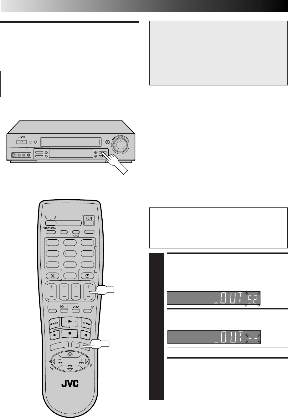
46
?
– –:– –
123
465
789
0
2
4
1
3
SUBSIDIARY SETTINGS (cont.)
Video
Channel Set
Video Channel (RF Output Channel) is the channel on
which your TV receives picture and sound signals from the
video recorder through the RF cable.
With AV or S-VIDEO
Connection
ACCESS VIDEO CHANNEL
SET MODE
1
Press and hold down STOP on the recorder until the
display panel shows the following.
SET VIDEO CHANNEL
2
Press PR – until the display panel shows "–OUT– –".
●Now the video channel is set to off.
EXIT VIDEO CHANNEL SET
MODE
3
Press OK.
To view picture signals from the video recorder, set
your TV to its AV mode. Refer to the instructions
supplied with your TV set for how to do this.
●
If you have connected the video recorder to
your TV via both the provided RF cable and a
21-pin SCART cable (AV connection), or via
the provided RF cable, an S-Video cable and
an audio cable (S-VIDEO connection), you do
not need the video channel so you have to set
the video channel to off. — Go to "With AV or
S-VIDEO Connection" below.
●
If you have connected the video recorder to your
TV via the provided RF cable only (RF connection),
you have to set the correct video channel
—
Go to
"With RF Connection" on page 47.
Before performing the following procedure, make
sure that:
nthe mains power cord is plugged into the mains outlet.
nthe video recorder is turned off and there is no cassette
inserted in the recorder.
nbatteries have been installed in the remote control.
OK
IMPORTANT
Perform the following steps only if —
— Video Channel Set has not been done correctly by the
Auto Set Up function (Z pg. 8).
— interference appears in the TV picture after you have
moved to a different area or a new station has started
broadcasting in your area.
— you change the connection between your recorder and
TV from RF connection to AV or S-VIDEO connection,
or vice versa.
PR
STOP
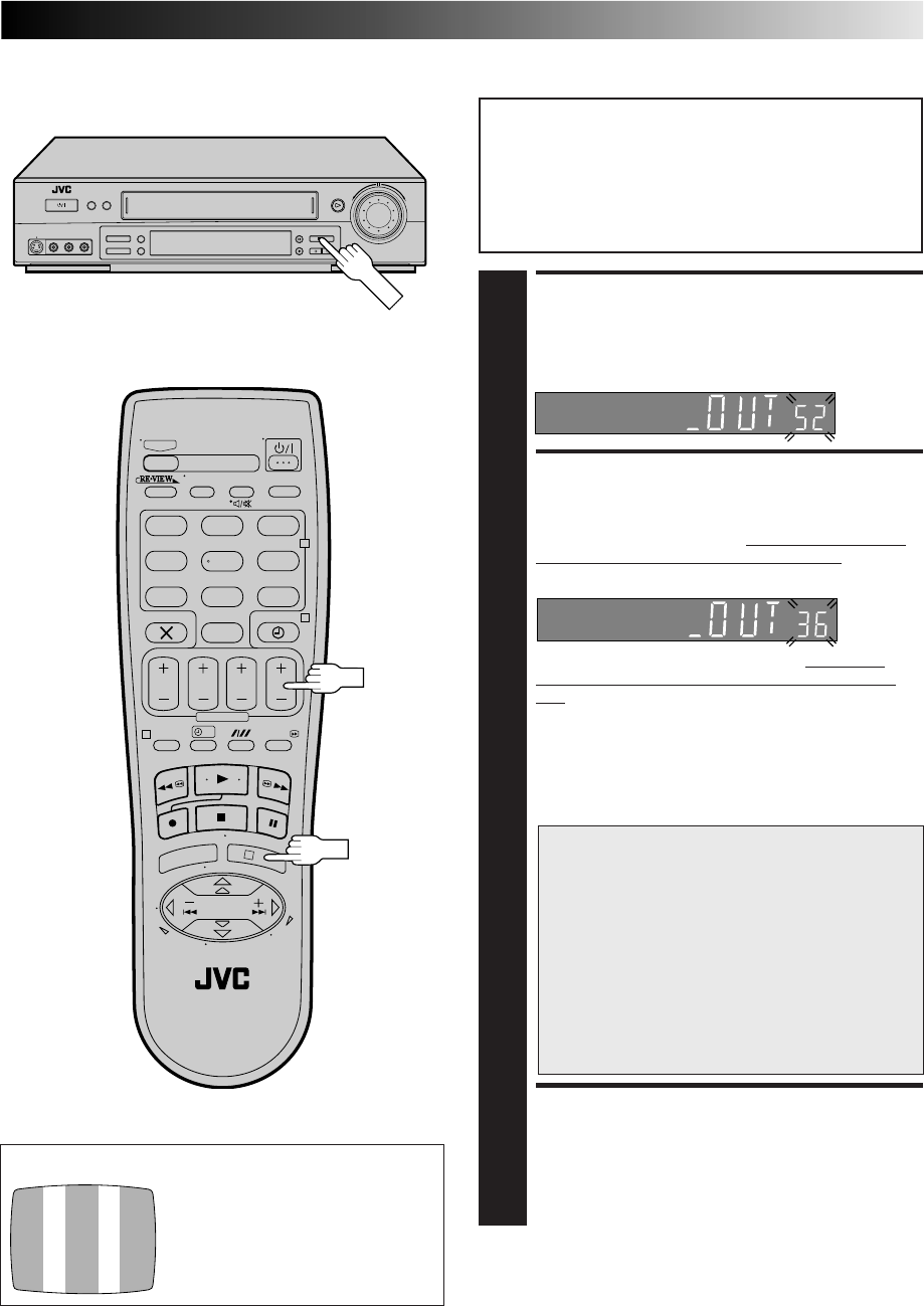
47
Before performing the following procedure, make
sure that:
nthe mains power cord is plugged into the mains outlet.
nthe video recorder is turned off and there is no cassette
inserted in the recorder.
nthe connected TV is turned on.
nbatteries have been installed in the remote control.
ACCESS VIDEO CHANNEL
SET MODE
1
Press and hold down STOP on the recorder until the
display panel shows the following.
SET VIDEO CHANNEL
2
Press PR+ or – to set the video recorder to a vacant
channel between 22 and 69 which is not occupied by
any local station in your area. Refer to list on page 54
for details of broadcast stations in your area.
Then set your TV to UHF channel 36. (Refer to the
instructions supplied with your TV set for how to do
this.)
●If the two vertical white bars appear clearly on the
screen as shown in the illustration at bottom left, go
to step 3.
●If the two vertical white bars do not appear clearly,
re-set the video recorder to another vacant channel
and try again.
IMPORTANT
●
If you set the video recorder to a channel which
is occupied by a local station or has
neighbouring channels that are occupied by
local stations, the picture reception quality will
be affected and some interference noise will
appear on the TV screen. Be sure to select a
vacant channel which has no broadcast on
neighbouring channels.
●
If you cannot obtain the two vertical white bars
clearly with any channel between 22 and 69,
consult your JVC dealer.
EXIT VIDEO CHANNEL SET
MODE
3
Press OK.
(Ex.) If channel 36 is available in your area
TEST SIGNAL
The channel on which the screen on
the left appears clearly in step 2 is
your Video Channel. To view picture signals from the video recorder, set
your TV to the Video Channel.
With RF Connection
?
– –:– –
123
465
789
0
2
4
1
3
OK
PR
STOP
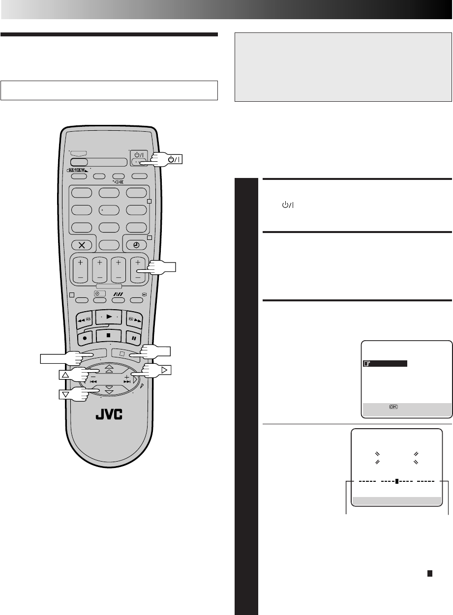
48
?
– –:– –
123
465
789
0
2
4
1
3
OK
MENU
SUBSIDIARY SETTINGS (cont.)
Tuner Set IMPORTANT
Perform the following steps only if —
— Auto Channel Set has not been set correctly by Auto Set
Up function (Z pg. 8) or Preset Download (Z pg. 9).
— you have moved to a different area or if a new station
starts broadcasting in your area.
Turn on the TV and select the VIDEO channel (or AV mode).
Your recorder needs to memorise all necessary stations in preset
positions in order to record TV programmes. Auto Channel Set
automatically assigns all receivable stations in your area to call
them up by using the PR buttons without going through any
vacant channel.
TURN ON THE RECORDER
1
Press .
ACCESS MAIN MENU
SCREEN
2
Press MENU.
PERFORM AUTO CHANNEL
SET
3
Move the highlight bar
(pointer) to "AUTO CH
SET" by pressing %fi, then
press OK or
#
.
●When you have
connected the video
recorder to a TV
offering T-V Link via
the AV connection
(Z pg. 6) and the TV
is turned on, the
recorder automati-
cally performs the
Preset Download
(Z pg. 9) even if
you select "AUTO
CH SET".
●The Auto Set screen
appears, and remains
on screen while the recorder searches for receivable
stations. As Auto Channel Set progresses, the " "
mark on the screen moves from left to right. Wait
until the screen as shown in step 4 appears.
●Auto Channel Set usually takes about 4 – 12 minutes;
the duration varies by area.
0
+++
End
Beginning
Auto Channel Set
MAIN MENU
MODE SET
AUTO CH SET
MANUAL CH SET
OUTPUT/INPUT SET
INITIAL SET
[5∞] =
[MENU] : EXIT
AUTO SET
PLEASE WAIT
[MENU] : EXIT
PR
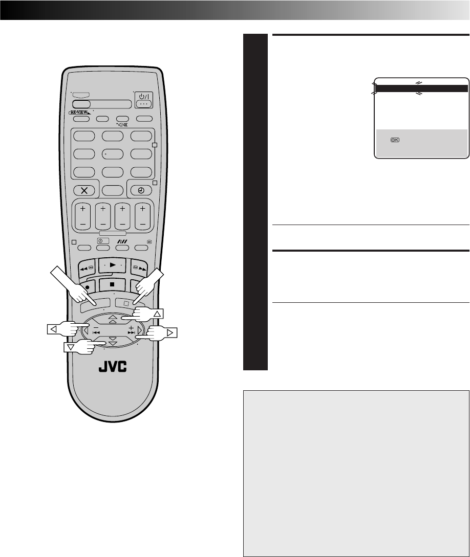
49
?
– –:– –
123
465
789
0
2
4
1
3
VIEW CONFIRMATION
SCREEN
4
After "SCAN COMPLETED"
is displayed on the screen
for about 5 seconds, a
Confirmation screen
looking like the one on the
right appears. The stations
your recorder located
appear on a Confirmation
screen — preset positions
(PR), channels (CH) and
station names (ID – Z pg. 53). The blueback screen
and the programme currently being broadcast by the
station which is blinking appear alternately for 8
seconds each.
To view the next page, use the %fi
@ #
button on the
remote control.
●The Guide Program numbers will also be set
automatically during Auto channel Set.
RETURN TO NORMAL
SCREEN
5
Press MENU.
●Using the Confirmation screen, you can skip or add
preset positions, enter station names and perform
other operations. Refer to pages 50 – 54 for the
procedures.
●Depending on reception conditions, the stations may,
on occasion, not be stored in order, and the station
names may not be stored correctly.
IMPORTANT
● In certain reception conditions, station names may not be
stored correctly, and auto Guide Program Number Set
may not work properly. If the Guide Program numbers
are not set properly, when you timer-record a TV
programme using the VIDEO Plus+ system, the recorder
will record a TV programme of a different station. When
programming the timer using the VIDEO Plus+ system,
be sure to check that the preset position corresponding to
the broadcasting station you wish to record has been
selected (Z pg. 18, "VIDEO Plus+ Timer Programming").
● Your video recorder memorizes all detected stations even
if reception of some of them is poor. In these cases
picture quality may be poor. To delete those stations
which have an unacceptable picture Z "Delete A
Channel" on page 51.
NOTES:
●
Fine tuning is performed automatically during Auto Channel
Set. If you wish to perform it manually, refer to page 51.
●
If, for any reason, you perform Auto Channel Set when the
aerial cable is not connected properly, "SCAN COMPLETED
-NO SIGNAL-" appears on the screen in step 4. When this
happens, make sure of the aerial connection and press OK;
Auto Channel Set will take place again.
PR CH ID PR CH ID
01 26 BBC1 08 ––––
02 33 BBC2 09 ––––
03 23 ITV 10 ––––
04 30 CH4 11 ––––
05 37 CH5 12 ––––
06 –––– 13 ––––
07 –––– 14 ––––
[5
∞ ]
= : EDIT
= [X] : DELETE
[MENU] : EXIT
5
5
5
OK
MENU
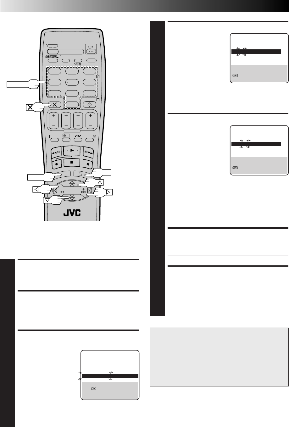
50
?
– –:– –
123
465
789
0
2
4
1
3
SUBSIDIARY SETTINGS (cont.)
Storing Channels Manually
To store channels that were not stored during Auto Set Up
(Z pg. 8), Preset Download (Z pg. 9) or Auto Channel Set
(Z pg. 48).
ACCESS MAIN MENU
1
Press MENU.
ACCESS CONFIRMATION
SCREEN
2
Press %fi to move the highlight bar (pointer) to
“MANUAL CH SET”, then press OK or
#
. The Confir-
mation screen appears.
SELECT POSITION
3
Press %fi
@ #
until an
open position in which
you want to store a
channel begins blinking,
then press OK. The Manual
Channel Set screen
appears.
NUMBER
(Ex.) To store in position 6.
The blueback screen and the
programme currently being
broadcast by the selected channel
appear alternately for 8 seconds
each.
The blueback screen and the
programme currently being
broadcast by the selected channel
appear alternately for 8 seconds
each.
5
5
PR CH ID PR CH ID
01 26 BBC1 08 ––––
02 33 BBC2 09 ––––
03 23 ITV 10 ––––
04 30 CH4 11 ––––
05 37 CH5 12 ––––
06 –––– 13 ––––
07 –––– 14 ––––
[5
∞ ]
= : EDIT
= [X] : DELETE
[MENU] : EXIT
OK
MENU
ATTENTION
Guide Program numbers are not set when channels are
stored manually. If an attempt is made at timer program-
ming with the VIDEO Plus+ system in this state, the
“GUIDE PROG SET” screen appears; set the Guide
Program numbers on this screen. Z “ATTENTION –
Regarding Guide Program Number Set” on page 19.
Or perform “Guide Program Number Set” (Z pg. 45).
The blueback screen and the
programme currently being
broadcast by the selected channel
appear alternately for 8 seconds
each.
SELECT BAND
4
Press %fi to change the
band between CH (regular)
and CC (cable), then
press
#
.
INPUT CHANNEL
5
Press the NUMBER keys to
input the channel number
you want to store.
●To input the registered
station name (ID – Z
pg. 53), press
#
until
"– – –␣ –" (ID setting)
begins blinking, then
press %fi.
●For fine tuning
adjustment, press
#
until "+/–" begins
blinking, then press
%fi. While tuning,
"+" or "–" appears.
●When "L-2 SELECT" is set to "A/V" or "SAT", the
"DECODER" setting cannot be changed (Z pg. 36).
ENTER NEW CHANNEL
INFORMATION
6
Press OK and the Confirmation screen appears.
●Repeat steps 3 through 6 as necessary.
CLOSE CONFIRMATION SCREEN
7
Press MENU.
●To change positions, see "Change Station Preset
Position" (Z pg. 51).
●If you wish to set station names other than the ones
registered in your recorder, Z "Set Stations (B)" on
page 52.
PR CH ID FINE DECODER
06 CH21
– –␣ – –
+/– OFF
[5∞] : SELECT
[ ] : CURSOR +=
: OK
[MENU] : EXIT
∞
∞
PR CH ID FINE DECODER
06 CH01
– –␣ – –
+/– OFF
[5∞] : SELECT
[ ] : CURSOR +=
: OK
[MENU] : EXIT
∞
∞
51
Perform steps 1 and 2 of "Storing Channels Manually" on
page 50 to access the Confirmation screen before continuing.
Change Station Preset
Position
SELECT ITEM
1
Press %fi
@ #
until the item you want to move begins
blinking. Then press OK and the station name (ID) and
its channel (CH) number begin blinking.
SELECT NEW POSITION
2
Press %fi
@ #
to move the station to the new preset
position, then press OK.
Example: If you moved the station in position 4 to
position 2, the stations originally in positions
2 and 3 each move down one space.
●Repeat steps 1 and 2 as necessary.
CLOSE CONFIRMATION SCREEN
3
Press MENU.
SELECT ITEM
1
Press %fi
@ #
until the item you want to delete begins
blinking.
DELETE CHANNEL
2
Press .
●The item directly beneath the cancelled one moves
up one line.
●Repeat steps 1 and 2 as necessary.
CLOSE CONFIRMATION SCREEN
3
Press MENU.
Delete A Channel
Perform steps 1 and 2 of "Storing Channels Manually" on
page 50 to access the Confirmation screen before continuing.
Perform steps 1 and 2 of "Storing Channels Manually" on
page 50 to access the Confirmation screen before continuing.
SELECT CHANNEL TO FINE-TUNE
1
Press %fi
@ #
until the channel you want to tune begins
blinking.
ACCESS MANUAL
CHANNEL SET SCREEN
2
Press OK twice. The Manual Channel Set screen
appears.
PERFORM TUNING
3
Press
#
until "+/–" begins blinking, then press %fi until
the picture is clearest. Then press OK.
●The Confirmation screen appears.
●Repeat steps 1 through 3 as necessary.
CLOSE CONFIRMATION SCREEN
4
Press MENU.
Fine-Tuning Channels
Already Stored
PR CH ID PR CH ID
01 26 BBC1 08 ––––
02 23 ITV 09 ––––
03 30 CH4 10 ––––
04 33 BBC2 11 ––––
05 37 CH5 12 ––––
06 –––– 13 ––––
07 –––– 14 ––––
[5
∞ ] : MOVE
: MANUAL CH SET
[MENU] : EXIT
PR CH ID PR CH ID
01 26 BBC1 08 ––––
02 33 BBC2 09 ––––
03 23 ITV 10 ––––
04 30 CH4 11 ––––
05 37 CH5 12 ––––
06 –––– 13 ––––
07 –––– 14 ––––
[5
∞
] : MOVE =
[MENU] : EXIT
5
5
5
5
SELECT DECODER MODE
1
Set "L-2 SELECT" to "DECODER" (Z pg. 36).
ACCESS CONFIRMATION
SCREEN
2
Perform steps 1 and 2 of "Storing Channel Manually" on
page 50.
SELECT POSITION
3
Press %fi
@ #
to select the channel position broadcast-
ing scrambled programmes, then press OK twice.
CHANGE DECODER SETTING
4
Press
#
until "OFF" (decoder setting) begins blinking,
and set it to "ON" by pressing %fi.
RETURN TO CONFIRMATION
SCREEN
5
Press OK.
●Repeat steps 3 through 5 as necessary.
CLOSE CONFIRMATION SCREEN
6
Press MENU.
When Receiving A
Scrambled Broadcast
NOTE:
Scrambled programmes are not currently broadcast in the U.K.
52
SUBSIDIARY SETTINGS (cont.)
SELECT STATION NAME
CHARACTER
1
Press
#
until the first letter
of the station name begins
blinking.
ENTER NEW CHARACTER
2
Press %fi to cycle through the characters (A–Z, 0–9, –,
*, +, (space) ) and stop when the desired character
is indicated, then press
#
to enter. Enter the remaining
characters the same way (maximum of 4).
After entering all characters, press OK.
●The Confirmation screen appears.
●If you make a mistake, press
@
until the incorrect
character begins blinking. Then enter the correct
character by pressing %fi.
CLOSE CONFIRMATION
SCREEN
3
Press MENU.
Set Stations (B)
Perform steps 1 and 2 of "Storing Channels Manually" on
page 50 to access the Confirmation screen before continuing.
SELECT ITEM
1
Press %fi
@ #
until the item you want begins blinking.
ACCESS MANUAL
CHANNEL SET SCREEN
2
Press OK twice.
SELECT NEW STATION
3
Press
#
until the station
name (ID) begins blinking,
then press %fi until the
new station’s name (ID)
you want to store begins
blinking.
Registered station names
(Z pg. 53) appear as you
press %fi.
SWITCH STATIONS
4
Press OK.
●The Confirmation screen appears.
●Repeat steps 1 through 4 as necessary.
CLOSE CONFIRMATION
SCREEN
5
Press MENU.
Set Stations (A)
Set station names that are registered in your recorder.
Perform steps 1 and 2 of "Storing Channels Manually" on
page 50 to access the Confirmation screen and then
perform steps 1 and 2 of "Set Stations (A)" on the left before
continuing.
Set station names other than the ones registered in your
recorder.
PR CH ID FINE DECODER
06 CH45
– –␣ – –
+/– OFF
[5∞] : CHANGE ID
[ ] : CURSOR +=
: OK
[MENU] : EXIT
∞
∞
PR CH ID FINE DECODER
06 CH45 BBC1 +/– OFF
[5∞] : A-Z, 0-9
[ ] : CURSOR +=
: OK
[MENU] : EXIT
∞
∞
NOTE:
The characters available for the station name (ID) are A–Z, 0–9,
–, *, +, (space) (maximum of 4).

53
TV Station And ID List
STATION NAME ID*
Anglia TV ANGL
ARD ARD
ARTE ARTE
BBC Group BBC
BBC1 BBC1
BBC2 BBC2
Berlin 1 BLN1
Berlin 2 BLN2
Border TV BORD
Bayern1 BR1
Bayern3 BR3
BRT1 BRT1
BRT2 BRT2
Children Ch CHLD
Canal + CH+
CNN CNN
Channel TV CHNL
Central TV CNTR
Channel 4 CH 4
Channel 5 CH 5
DRS DRS
DR TV DRTV
DSF DSF
Euronews EURN
Euronews EURO
Eurosports EURS
France1 FR1
France2 FR2
France3 FR3
Granada TV GRNA
Grampian TV GRMP
Hessen1 HR1
Hessen3 HR3
HRT HRT
HTV HTV
ITV Network ITV
Kabelkanal KABL
London LNDN
MDR MDR
MTV MTV
Nord3 N3
NDR1 NDR1
NDR3 NDR3
NED1 NED1
NED2 NED2
NED3 NED3
Network 2 NET2
NRK NRK
N-TV N-TV
Offener Kanal OKAN
ORF1 ORF1
ORF2 ORF2
ORF3 ORF3
OWL 3 OWL3
Premiere PRMI
PR07 PR07
RAI1 RAI1
RAI2 RAI2
RAI3 RAI3
RB1 RB1
RB3 RB3
Rikisutvarpid-S RKPS
RTBF 1 RTB1
RTBF 2 RTB2
RTE 1 RTE1
RTL RTL
RTL 2 RTL2
RTP RTP
STATION NAME ID*
SAT SAT
SAT 1 SAT1
Scottish TV SCOT
SC4 SC4
SDR SDR
SDR1 SDR1
SFB1 SFB1
SFB3 SFB3
SKY SKY
Sky One SKY1
Sky Net SKYN
Sport SPRT
SR 1 SR1
Super RTL SRTL
STV Test STVT
STV 1 STV1
STV 2 STV2
Suedwest3 SWR
SWF 1 SWF1
Schweiz4 SWZ4
TYNE TEES TEES
Text TEXT
TF1 TF1
TNT int TNT
TRT int TRT
TSI TSI
TSR TSR
TSW TSW
TVE TVE
TV Polonia TVPA
TVP 1 TVP1
TVP 2 TVP2
TVS TVS
TV2 TV2
TV5 TV5
Tele Zurich TZUR
Ulster TV ULST
Veronica VERN
VIVA VIVA
VIVA2 VIV2
VOX VOX
VTM VTM
VT4 VT4
West1 WDR1
West3 WDR3
YLE 1 YLE1
YLE 2 YLE2
Yorkshire TV YORK
ZDF ZDF
Zurich 1 ZUR1
3SAT 3SAT
* The "ID" abbreviation is what is shown on-screen in lieu of the
station name. The "ID" abbreviation is listed in the Confirma-
tion screen and is displayed on the TV screen each time the
recorder is tuned to a different station.

54
SUBSIDIARY SETTINGS (cont.)
TV Station Channel Number Guide
Only the main stations are listed. There are in addition many relay stations, and full lists are available from the BBC
and ITV.
BBC1 BBC2 ITV CH4 CH5
London & South-East
Bluebell Hill ......................... 40 46 43 65 —
Crystal Palace....................... 26 33 23 30 37
Dover ................................... 50 56 66 53 —
Heathfield ............................ 49 52 64 67 —
Oxford ................................. 57 63 60 53 49
South-West
Beacon Hill .......................... 57 63 60 53 —
Caradon Hill ........................ 22 28 25 32 —
Huntshaw Cross ................... 55 62 59 65 67
Redruth ................................ 51 44 41 47 37
Stockland Hill ...................... 33 26 23 29 —
Channel Islands
Fremont Point....................... 51 44 41 47 —
South
Hannington .......................... 39 45 42 66 35
Midhurst............................... 61 55 58 68 —
Rowridge.............................. 31 24 27 21 —
West
Mendip ................................ 58 64 61 54 37
East
Sandy Heath......................... 31 27 24 21 39
Sudbury................................ 51 44 41 47 35
Tacolneston .......................... 62 55 59 65 52
Midlands
Ridge Hill ............................. 22 28 25 32 35
Sutton Coldfield ................... 46 40 43 50 37
The Wrekin .......................... 26 33 23 29 35
Waltham .............................. 58 64 61 54 35
North
Belmont ............................... 22 28 25 32 56
Emley Moor.......................... 44 51 47 41 37
BBC1 BBC2 ITV CH4 CH5
North-West
Caldbeck .............................. 30 34 28 32 56
Winter Hill ........................... 55 62 59 65 48
North-East
Bilsdale West Moor .............. 33 26 29 23 35
Chatton ................................ 39 45 49 42 —
Pontop Pike .......................... 58 64 61 54 68
Scotland
Angus ................................... 57 63 60 53 —
Black Hill ............................. 40 46 43 50 37
Sandale ................................ 22 ————
Caldbeck .............................. — 34 28 32 56
Creigkelly ............................. 31 27 24 21 48
Darvel .................................. 33 26 23 29 35
Durris ................................... 22 28 25 32 67
Eitshal .................................. 33 26 23 29 —
Keelylang Hill ...................... 40 46 43 50 —
Knock More ......................... 33 26 23 29 —
Rosemarkie .......................... 39 45 49 42 67
Rumster Forest...................... 31 27 24 21 —
Selkirk .................................. 55 62 59 65 52
Wales
Blaenplwyf ........................... 31 27 24 21 56
Carmel ................................. 57 63 60 53 —
Llanddona ............................ 57 63 60 53 —
Moel-y-Parc ......................... 52 45 49 42 —
Presely ................................. 46 40 43 50 37
Wenvoe ................................ 44 51 41 47 —
Northern Ireland
Brougher Mountain .............. 22 28 25 32 —
Divis .................................... 31 27 24 21 37
Limavady ............................. 55 62 59 65 —
For customers in the U.K.
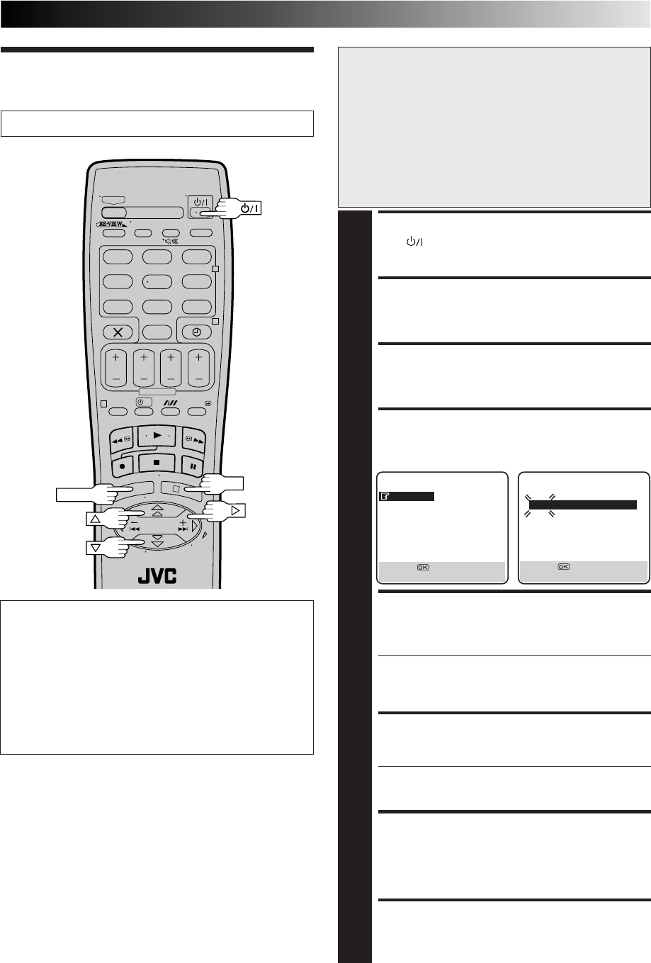
55
?
– –:– –
123
465
789
0
2
4
1
3
Just Clock
The Just Clock function provides accurate time keeping
through automatic adjustments at regular intervals, by
reading data from a PDC signal.
The Just Clock option can be set "ON" or "OFF" at the
Clock Set screen (the default setting is "ON"). Press OK
until the Just Clock setting begins blinking, then press %fi
to change the setting.
IMPORTANT: If you turn the Just Clock function off, the
accuracy of your recorder’s built-in clock may be im-
paired, which could adversely affect timer recording.
TURN THE RECORDER ON
1
Press .
ACCESS MAIN MENU SCREEN
2
Press MENU.
ACCESS INITIAL SET SCREEN
3
Move the highlight bar (pointer) to "INITIAL SET" by
pressing %fi, then press OK or
#
.
ACCESS CLOCK SET SCREEN
4
Move the highlight bar (pointer) to "CLOCK SET" by
pressing %fi, then press OK or
#
. The Clock Set screen
appears.
SET DATE AND TIME
5
Press %fi to set the time, then press OK or
#
. The "date"
display begins blinking. Repeat the same procedure to
set the date and year.
●When you set the time, press and hold %fi to
change the time by 30 minutes.
●When you set the date, press and hold %fi to
change the date by 15 days.
SET JUST CLOCK
6
The default setting is “ON”. Set as desired by pressing
%fi, then press OK or
#
.
●For the Just clock function, Z "Just Clock" on the left.
●If you set to “OFF”, you can disregard the next step as
you won’t be able to receive regular clock adjustments.
SET CLOCK DATA SOURCE PRESET
7
The recorder is preset to receive clock setting and
adjustment data from preset position 1. Press %fi to set
the preset position to the number representing the
station transmitting clock setting data (BBC1, BBC2,
etc.), then press OK or
#
.
START CLOCK OPERATION
8
Press MENU.
Clock Set
Turn on the TV and select the VIDEO channel (or AV mode).
NOTES:
●
Just Clock (when set to "ON") adjusts the recorder's built-in
clock every hour, except for 23:00, 0:00, 1:00 and 2:00.
●
Just Clock is not effective when . . .
– the recorder’s power is on.
– the recorder is in the Timer mode.
– a difference of more than 3 minutes exists between the
built-in clock’s time and the actual time.
– the recorder is in the Auto Satellite Prog Rec mode
(
Z
pg. 30)
– "L-2 SELECT" is set to "SAT". (
Z
pg. 36)
●
If Just Clock is set to "ON", the recorder’s clock is automati-
cally adjusted at the start/end of Summer Time.
●
Just Clock may not function properly in poor reception
conditions.
IMPORTANT
If you performed Auto Set Up (Z pg. 8), Preset Download
(Z pg. 9) or Auto Channel Set (Z pg. 48), without ever
having set the clock previously, the recorder's built-in
clock is also set automatically.
Perform the following steps only if —
— Auto Clock Set has not been performed correctly by
Auto Set Up, Preset Download or Auto Channel Set.
or
— the recorder's memory backup has expired.
or
— you want to change Just Clock setting (Z "Just Clock" in
the left column).
INITIAL SET
CLOCK SET
GUIDE PROG SET
SAT CONTROL SET
[5∞] =
[MENU] : EXIT
CLOCK SET
TIME DATE YEAR
0: 00 01 . 01 00
JUST CLOCK: ON
TV PR. : 1
[5∞] =
[MENU] : EXIT
OK
MENU

56
PLAYBACK
Q. What happens if the end of the tape is reached
during playback or search?
A. The tape is automatically rewound to the beginning.
Q. Can the video recorder indefinitely remain in the
still mode?
A. No. It stops automatically after 5 minutes to protect
the heads.
Q. During search, slow, still and frame-by-frame
playback, I can’t hear any audio. What’s the
problem?
A. This is normal.
Q. When returning from multi-speed search to normal
playback, the picture is disturbed. Should I be
concerned about this?
A. No, it is normal.
Q. Noise bars appear during multi-speed search. What’s
the problem?
A. This is normal.
Q. Sometimes, during Index Search, the video recorder
can’t find the programme I want to see. Why not?
A. There may be index codes too close together.
ATTENTION
This recorder contains microcomputers. External electronic noise or interference could cause malfunctioning. In such cases,
switch the recorder off and unplug the mains power cord. Then plug it in again and turn the recorder on. Take out the cassette.
After checking the cassette, operate the unit as usual.
RECORDING
Q. When I pause and then resume a recording, the end
of the recording before the pause is overlapped by
the beginning of the continuation of recording. Why
does this happen?
A. This is normal. It reduces distortion at the pause and
resume points.
Q. Can the video recorder indefinitely remain in the
Record-Pause mode?
A. No. The video recorder shuts off automatically after 5
minutes to protect the heads.
Q. What happens if the tape runs out during recording?
A. The video recorder automatically rewinds it to the
beginning or, if Timer Recording, the cassette is
ejected.
TIMER RECORDING
Q. " " and "‰" remain lit on the display panel. Is there
a problem?
A. No. This is a normal condition for a timer recording
in progress.
Q. Can I programme the timer while I’m watching a
tape or a TV broadcast?
A. You won’t see the picture as it is replaced by the on-
screen menu, but the audio from the program or tape
you’re viewing can be heard.
Questions And Answers
SUBSIDIARY INFORMATION

57
Before requesting service for a problem, use this chart to see if you can correct the trouble yourself. Small problems are often easily
corrected, and this can save you the trouble of sending your video recorder off for repair.
POSSIBLE CAUSE
●The mains power cord is disconnected.
●“‰“ is displayed on the display
panel with Auto Timer set to "OFF".
●The batteries are discharged.
SYMPTOM
1. No power is applied to the recorder.
2. The clock is functioning properly,
but the recorder cannot be powered.
3. The remote control won’t function.
CORRECTIVE ACTION
Connect the mains power cord.
Press the ‰ button to turn the “‰“
indicator off.
Replace the dead batteries with new
ones.
SYMPTOM
1. The tape does not run during
recording.
2. The tape will not rewind or fast-
forward.
CORRECTIVE ACTION
Press PLAY to turn the “ “ indicator
off.
Check the cassette.
SYMPTOM
1. The playback picture does not
appear while the tape is running.
2. Noise appears during visual search.
3. Noise appears during normal
playback.
4. The playback picture is blurred or
interrupted while TV broadcasts are
clear or "USE CLEANING
CASSETTE" message appears on the
screen.
5. Breaks are noticeable in Hi-Fi
soundtrack.
POSSIBLE CAUSE
●If you’re using the RF connection . . .
. . . the TV receiver’s channel selector
is not set to the VIDEO channel.
. . . the recorder's VIDEO channel
has not been correctly set.
●If you’re using the AV or S-VIDEO
connection, the TV receiver is not set
to the AV mode.
●This is normal.
●The automatic tracking mode is
engaged.
●The video heads may be dirty.
●Automatic tracking is engaged.
CORRECTIVE ACTION
If you are using the RF connection . . .
. . . set the TV receiver to the VIDEO
channel. (Z pg. 8)
. . . Perform "Video Channel Set"
(Z pg. 46)
If you are using the AV or S-VIDEO
connection, set the TV to its AV mode.
Try manual tracking (Z pg. 24).
Use a dry cleaning cassette JVC
TCL-2U or consult your JVC dealer.
Engage and adjust tracking manually
(Z pg. 24) or press AUDIO to
change the soundtrack to "NORM"
(Z␣ pg.␣ 25).
POSSIBLE CAUSE
●““ is displayed on the display
panel.
●The tape is already fully rewound or
fast-forwarded.
CORRECTIVE ACTION
Insert a cassette, or using adhesive
tape, reseal the slot where the tab
was removed.
Set to the desired preset.
POSSIBLE CAUSE
●There is no cassette loaded, or the
cassette loaded has had its Record
Safety tab removed.
●“L-1”, “L-2”, “SAT”, “F-1” or “S-1”
has been selected as the input
mode.
SYMPTOM
1. Recording cannot be started.
2. TV broadcasts cannot be recorded.
Troubleshooting
POWER
TAPE TRANSPORT
PLAYBACK
RECORDING

58
SUBSIDIARY INFORMATION (cont.)
CORRECTIVE ACTION
Re-perform the clock and/or timer
settings.
Press ‰ and confirm that “‰“ is
displayed on the display panel.
Timer programming can’t be
performed while a timer recording is
in progress. Wait until it finishes.
Load a cassette with the Record
Safety tab intact, or cover the hole
using adhesive tape.
Remove the cassette and cover the hole
with adhesive tape, or insert a cassette
with the Record Safety tab intact.
Check the programmed data and re-
programme as necessary, then press
‰ again.
The programme may not have been
recorded in its entirety. Next time make
sure you have enough time on the tape
to record the entire programme.
Refer to "Guide Program Number Set"
and re-perform the procedure (Z pg. 45).
SYMPTOM
1. Timer recording won’t work.
2. Timer programming is not possible.
3. “‰“ and “]“ on the display
panel won’t stop blinking.
4. The cassette is automatically
ejected, and “‰“ and “]“ on the
display panel won’t stop blinking.
5. “‰“ blinks for 10 seconds and the
Timer mode is disengaged.
6. The cassette is automatically
ejected, the power shuts off and
“‰“ and “]“ won’t stop
blinking.
7. The VIDEO Plus+ system does not
timer-record properly.
POSSIBLE CAUSE
●The clock and/or the timer have
been set incorrectly.
●The timer is not engaged.
●Timer recording is in progress.
●The timer is engaged but there’s no
cassette loaded.
●The loaded cassette has had its
Record Safety tab removed.
●‰ has been pressed when there are
no programs in memory, or the timer
record information has been
programmed incorrectly.
●The end of the tape was reached
during timer recording.
●The recorder’s preset positions have
been set incorrectly.
CORRECTIVE ACTION
Position the camcorder so its
microphone is away from the TV.
Turn the TV’s volume down.
If you need the skipped channels,
restore them (Z pg. 50).
Press PAUSE to pause the recording,
change presets, then press PLAY to
resume recording.
Perform manual setting again.
Turn off the recorder once and connect
the TV aerial cable to the recorder
properly, then turn on the recorder
again. The recorder will try Auto Set
Up again (Z pg. 8).
Turn off the recorder once and connect
the fully-wired 21-pin SCART cable to
the recorder properly, then turn on the
recorder again. Then perform Preset
Download again (Z pg. 9).
SYMPTOM
1. Whistling or howling is heard from
the TV during camcorder record-
ing.
2. When scanning channels, some of
them are skipped over.
3. The preset cannot be changed.
4. Channel settings that were made
manually seem to have changed or
disappeared.
5. No channels are stored in the
recorder's memory.
POSSIBLE CAUSE
●The camcorder’s microphone is too
close to the TV.
●The TV’s volume is too high.
●Those channels have been desig-
nated to be skipped.
●Recording is in progress.
●After the manual settings were
made, Auto Channel Set was
performed.
●The TV aerial cable was not
connected to the recorder when
Auto Set Up was performed.
●The fully-wired 21-pin SCART cable
was not connected between TV and
the recorder when Preset Download
was performed.
3. Tape-to-tape editing is not possible.
4. Camcorder recording is not
possible.
●The source (another video recorder,
camcorder) has not been properly
connected.
●All necessary power switches have
not been turned on.
●The input mode is not correct.
●The camcorder has not been
properly connected.
●The input mode is not correct.
Confirm that the source is properly
connected.
Confirm that all units’ power switches
are turned on.
Set the input mode to “L-1”,“L-2”,
“F-1” or “S-1”.
Confirm that the camcorder is
properly connected.
Set the input mode to “L-1”,“L-2”,
“F-1” or “S-1”.
OTHER PROBLEMS
TIMER RECORDING
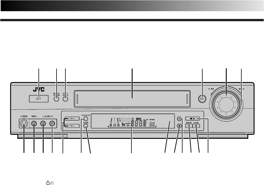
59
FRONT VIEW
1 2 3 45
*
^
0#
6
7
9
8q
&)(!@ $ %
1STANDBY/ON Button turns recorder on/off
(loading a cassette also turns power on).
2DIGITAL TBC/NR Button enables/disables
Digital TBC/NR. Z pg. 24
3SP/LP Button selects tape speed. Z pg. 16
4Cassette Loading Slot is where cassette is
inserted; door closes, "cassette loaded" indicator
lights up on front display panel.
5PLAY Button plays back tape Z pg. 14; cancels
Pause, Still, Slow, Search modes. Z pg. 15
6JOG Dial plays back frame by frame during Still
or Play mode. Z pg. 15
7SHUTTLE Ring rewinds or fast-forwards tape
during Stop mode Z pg. 14; performs forward
and reverse slow-motion and search during Still
or Play mode. Z pg. 15
8S-VIDEO Input Connector enables S-VIDEO
connection to camcorder or second recorder.
Z pg. 33
9VIDEO Input Connector enables easy connection
of video output from another recorder or
camcorder for editing. Z pg. 33
0AUDIO Input Connector [L] enables easy
connection of audio output (mono) from an-
other recorder, camcorder or other source for
editing. Z pg. 33
!AUDIO Input Connector [R] enables easy
connection of audio output (Hi-Fi) from another
recorder, camcorder or other source for editing.
Z pg. 33
Index
@PR +/– Buttons select a preset position.
Z pg. 16
#S-VHS ET Button enables/disables S-VHS ET
mode; lights up during S-VHS ET mode.
Z pg. 27
$SAT‰ Button enables/disables the Auto Satellite
Prog Rec mode; lights up during Auto Satellite
Prog Rec mode; blinks while Auto Satellite Prog
recording is in progress. Z pg. 31
%Display Panel provides clear view of various
displays and indicators. Z pg. 61
^Infrared Beam Receiving Window is where
remote control should be aimed when in use.
&RECORD Button starts regular recording (press
once), Instant Timer Recording (press twice);
sets duration of ITR. Z pg. 16, 17
*PAUSE Button stops tape temporarily during
recording Z pg. 16; stops tape temporarily
during playback; plays back frame by frame
with each additional press. Z pg. 15
(INSERT Button engages Insert Editing mode.
Z pg. 39
)A. DUB Button engages Audio Dubbing mode.
Z pg. 37
qSTOP/EJECT Button stops tape; ejects tape
during Stop mode. Z pg. 14
* Attach the provided connector cover when you do not use the front panel connectors.
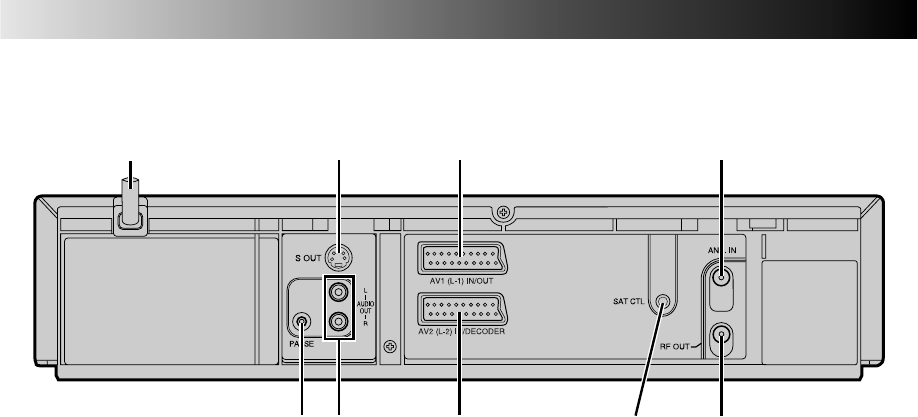
60
1
98
32 4
5 7
6
1Mains Power Cord supplies power to recorder.
Z pg. 6
2S OUT Connector enables S-VIDEO connection
to TV or second recorder. Z pg. 7, 34
3AV1 (L-1) IN/OUT Connector enables AV
connection to TV or second recorder; input
recordable when "L-1" selected. Z pg. 6, 34
4ANT. IN Connector enables connection of
aerial. Z pg. 6
5Remote PAUSE Connector enables connection
to second recorder equipped with R.A. Edit
connector, or to JVC camcorder equipped with
Master Edit Control, for easy editing. Z pg. 33
REAR VIEW
SUBSIDIARY INFORMATION (cont.)
6AUDIO OUT (L/R) Connectors enable
connection of audio cassette recorder, TV or
second video recorder for dubbing. Z pg. 44
7AV2 (L-2) IN/DECODER Connector enables
connection of satellite receiver, decoder or
second recorder; input recordable when "L-2"
selected. Z pg. 30, 34
8SAT CTL Connector enables connection of the
provided Satellite Controller for timer recording
with a satellite receiver. Z pg. 12
9RF OUT Connector enables connection to
aerial terminal of TV receiver. Z pg. 6
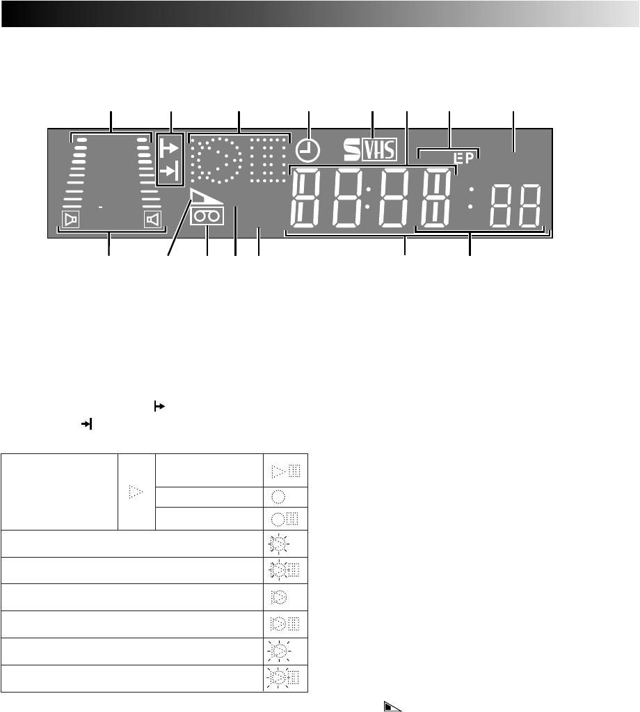
61
1B.E.S.T. Picture System Display lights from
bottom to top while B.E.S.T. is active. Z pg. 28
Audio Level Indicator displays audio input and
output levels.
2Programme Time Indicators show the
programme start time ( ) and the programme
stop time ( ) for timer-recording. Z pg. 20
3Symbolic Mode Indicators
4"Timer" Indicator lights when ‰ has been
pressed to engage Timer mode. Z pg. 19, 21
5S-VHS Indicator lights when a cassette marked
S-VHS is inserted with S-VHS mode set to "ON",
when an S-VHS-recorded tape or S-VHS ET-
recorded tape is played back, or when S-VHS ET
mode is engaged. Z pg. 27
6Channel Display shows preset position where
the station currently being received is stored.
Clock Display shows current time. Z pg. 10
7Tape Speed Indicators display mode of record-
ing; light during Record or Play mode. Z pg. 16
* EP is only for NTSC playback.
8Instant REVIEW Indicator blinks after timer-
recording and shows how many programmes
have been timer-recorded. Z pg. 26
9Audio Mode Indicator displays audio output
mode currently selected. Z pg. 25
0Tape Remaining Time Indicator displays time
remaining on tape when certain buttons are
pressed. Z pg. 17
!"Cassette Loaded" Mark lights once a cassette is
inserted; remains lit until cassette ejected.
@PDC Indicator lights when PDC has been
engaged for timer recording. Z pg. 19, 21
* VPS (Video Programme System) recording is not
currently available in the U.K. and not possible with
this recorder.
#VCR Indicator lights when the video recorder is
in the video mode. At this point, the TV auto-
matically enters AV mode. Z pg. 14
$Counter shows time elapsed since playback or
recording began.
With displayed, shows time remaining from
current tape position to end of tape (Z pg. 17).
Counter, Preset Position*, Clock and Tape
Remaining Time Display appear alternately
when – –:– – (Display) is pressed.
* Preset Position is not displayed during playback.
%Mode shows external input mode selected (L-1,
L-2, SAT*, F-1 or S-1).
* When "L-2 SELECT" is set to "SAT" (
Z
pg. 36), "SAT"
appears instead of "L-2".
DISPLAY PANEL
REVIEW
SP
VPS/PDC
+8
4
0
6
15dB
NORM
@
!0 $%9
1 5 6 873 42
VCR
#
STILL:
SLOW:
RECORD:
RECORD PAUSE:
PLAY:
FF/REW VARIABLE
SEARCH:
AUDIO DUBBING:
AUDIO DUBBING PAUSE:
INSERT:
INSERT PAUSE:
AV INSERT:
AV INSERT PAUSE:
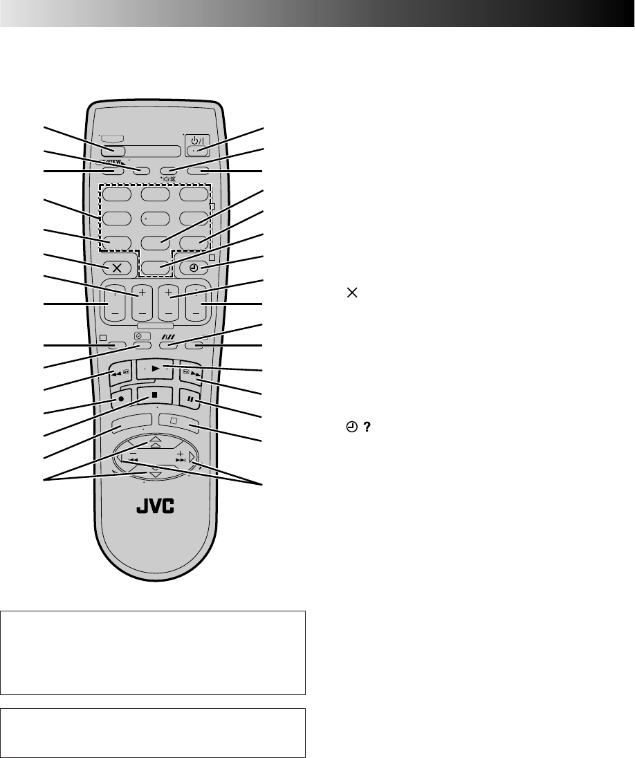
62
REMOTE CONTROL 1TV Button enables remote control of connected
TV. Z "Operating JVC TVs" on page 63
2TV/VCR Button switches connected TV's mode
between TV and AV. Z pg. 14 and "Operating
JVC TVs" on page 63
3REVIEW Button "reviews" timer-recorded
programme. Z pg. 26
4NUMBER Keys are used in preset position
selection Z pg. 16, VIDEO Plus+ timer pro-
gramming Z pg. 18.
5PDC Button enables/disables PDC recording.
Z pg. 19, 21
* VPS (Video Programme System) recording is not
currently available in the U.K. and not possible with
this recorder.
6 Button cancels timer-programme. Z pg. 22
0000 Button resets counter to 0:00:00. Z pg. 17
7STOP +/– Button inputs programme Stop Time.
Z pg. 20
8START +/– Button accesses Regular Program
screen; inputs programme Start Time. Z pg. 20
9PROG Button accesses VIDEO Plus+ Program
screen. Z pg. 18
0 Button accesses Program screens/displays
to check the programme that you have pro-
grammed (next programme's information
screen/display appears each time button is
pressed). Z pg. 22
!Rewind [REW] Button rewinds tape ; initiates
reverse high-speed search. Z pg. 14, 15
@Record Button — same as button on recorder.
Z pg. 16, 17
#Stop Button — same as button on recorder.
Z pg. 14
$MENU Button accesses Menu screen. Z pg. 11
%%fi Button is used for selection in on-screen
menus. Z pg. 11
TV PR +/– selects the connected TV's/ satellite
receiver's channel. Z "Operating JVC TVs" on
page 63
SUBSIDIARY INFORMATION (cont.)
T
V
P
R
+
T
V
P
R
–
T
V
–
T
V
+
TV
0000
STOP
FIN
MENU
OK
TV/VCR
DAILY/QTDN.
VPS/PDC
AUX
?
WEEKLY/HEBDO
PROG 30 SEC
– –:– –
AUDIO
123
465
789
0
DATE
START
DEBUT
PR
2
4
1
3
E
N
T
E
R
/
E
N
T
R
E
E
EXPRESS
t
u
p
2
7
6
1
8
3
9
4
0
!
@
#
$
^
&
w
e
r
o
i
%Q
5
y
q
)
(
*
Buttons with a small dot on the left side of the
name can also be used to operate your JVC TV
while holding down the TV button.
Z "Operating JVC TVs" on page 63.
This remote control transmits A code signals
only; it is not applicable to B code signals.
63
^STANDBY/ON Button — same as button on
recorder.
&AUDIO Button changes output sound mode.
Z pg. 25
(TV Muting) Button mutes sound of
connected TV. Z "Operating JVC TVs" in the
right column.
*– –:– – (Display) Button switches display
between clock time, tape remaining time,
counter readings and preset position*. Z pg. 17
* Preset position is not displayed during playback.
(DAILY Button enables timer recording of daily
serials. Z pg. 19, 21
)WEEKLY Button enables timer recording of
weekly serials. Z pg. 19, 21
qAUX Button selects recorder's auxiliary input
mode. Z pg. 33, 34
w‰ (TIMER) Button engages timer-standby
mode. Z pg. 19, 21
eDATE +/– Button inputs date of programme for
timer recording. Z pg. 20
rPR +/– Button — same as button on recorder.
Z pg. 16
tAuto Tracking Button ( ) enables/disables
auto tracking mode during playback Z pg. 24
SP/LP Button selects tape speed. Z pg. 16
y30 SEC Button initiates a 30-second period of
fast-motion playback. Z pg. 26
uPlay Button — same as button on recorder.
Z pg. 14, 15
iFast Forward [FF] Button fast-forwards tape;
initiates forward high-speed search. Z pg. 14, 15
oPause Button — same as button on recorder.
Z pg. 15, 16
pOK Button enters selections made in on-screen
menus. Z pg. 11
Q
@ #
Button initiates functions such as Index
Search Z pg. 26, variable-speed search, frame
by frame playback. Z pg. 15
TV +/– Button controls volume of connected
TV. Z "Operating JVC TVs" in the right
column.
How To Use
The remote control can operate most of your video recorder's
functions, as well as basic functions of JVC TV sets. (See
below.)
●Point the remote control toward the sensor window.
●The maximum operating distance of the remote control
is about 8 m.
Operating JVC TVs
To operate your TV, while holding down the TV button,
press the corresponding button: STANDBY/ON , TV/
VCR, TV PR +/–, TV +/–, (TV Muting).
NOTES:
●
When inserting the batteries, be sure to insert in the
correct directions as indicated under the battery cover.
●
Depending on the type of JVC TV, there may be cases
where some or all functions cannot be operated using the
remote control.
●
If the remote control doesn't work properly, remove its
batteries, wait a short time, replace the batteries and then
try again.

GENERAL
Power requirement : AC 220 V – 240 V`,
50 Hz/60 Hz
Power consumption
Power on : 23 W
Power off : 5.2 W
Temperature
Operating : 5°C to 40°C
Storage : –20°C to 60°C
Operating position : Horizontal only
Dimensions (WxHxD) : 400 mm x 94 mm x 344 mm
Weight : 4.2 kg
Format : S-VHS/VHS PAL standard
Maximum recording time
(SP) : 240 min. with E-240 video
cassette
(LP) : 480 min. with E-240 video
cassette
VIDEO/AUDIO
Signal system : PAL-type colour signal and
CCIR monochrome signal,
625 lines/50 fields
Recording system : DA4 (Double Azimuth) helical
scan system
Signal-to-noise ratio : 45 dB
Horizontal resolution : 250 lines (VHS)
400 lines (S-VHS)
Frequency range : 70 Hz to 10,000 Hz
(Normal audio)
20 Hz to 20,000 Hz
(Hi-Fi audio)
Input/Output : 21-pin SCART connectors
(IN/OUT x 1,
IN/DECODER x 1)
RCA connectors
(VIDEO IN x 1, AUDIO IN x 1,
AUDIO OUT x 1)
S-Video connectors
(IN x 1, OUT x 1)
TUNER/TIMER
TV channel storage
capacity : 99 positions
(+AUX position)
Tuning system : Frequency synthesized tuner
Channel coverage :
VHF 44.5 MHz –
143 MHz/
143 MHz – 470 MHz
UHF 470
MHz
– 862 MHz
Aerial output : UHF channels 22 – 69
(Adjustable)
Memory backup time : Approx. 60 min.
ACCESSORIES
Provided accessories : RF cable,
Satellite Controller,
Infrared remote control unit,
"AA" battery x 2,
S-VHS ET labels
Specifications shown are for SP mode unless otherwise
specified.
E.& O.E. Design and specifications subject to change without
notice.
SPECIFICATIONS
HR-S7700/7722EK
COPYRIGHT © 2000 VICTOR COMPANY OF JAPAN, LTD. EK Printed in Japan
0300IYV
*
ID
*
VP
VICTOR COMPANY OF JAPAN, LIMITED
