Jvc Hr S9400E Users Manual
HR-S9400EH to the manual 8c93fb62-3439-f064-0511-8bc551918d63
2015-01-26
: Jvc Jvc-Hr-S9400E-Users-Manual-326272 jvc-hr-s9400e-users-manual-326272 jvc pdf
Open the PDF directly: View PDF ![]() .
.
Page Count: 64
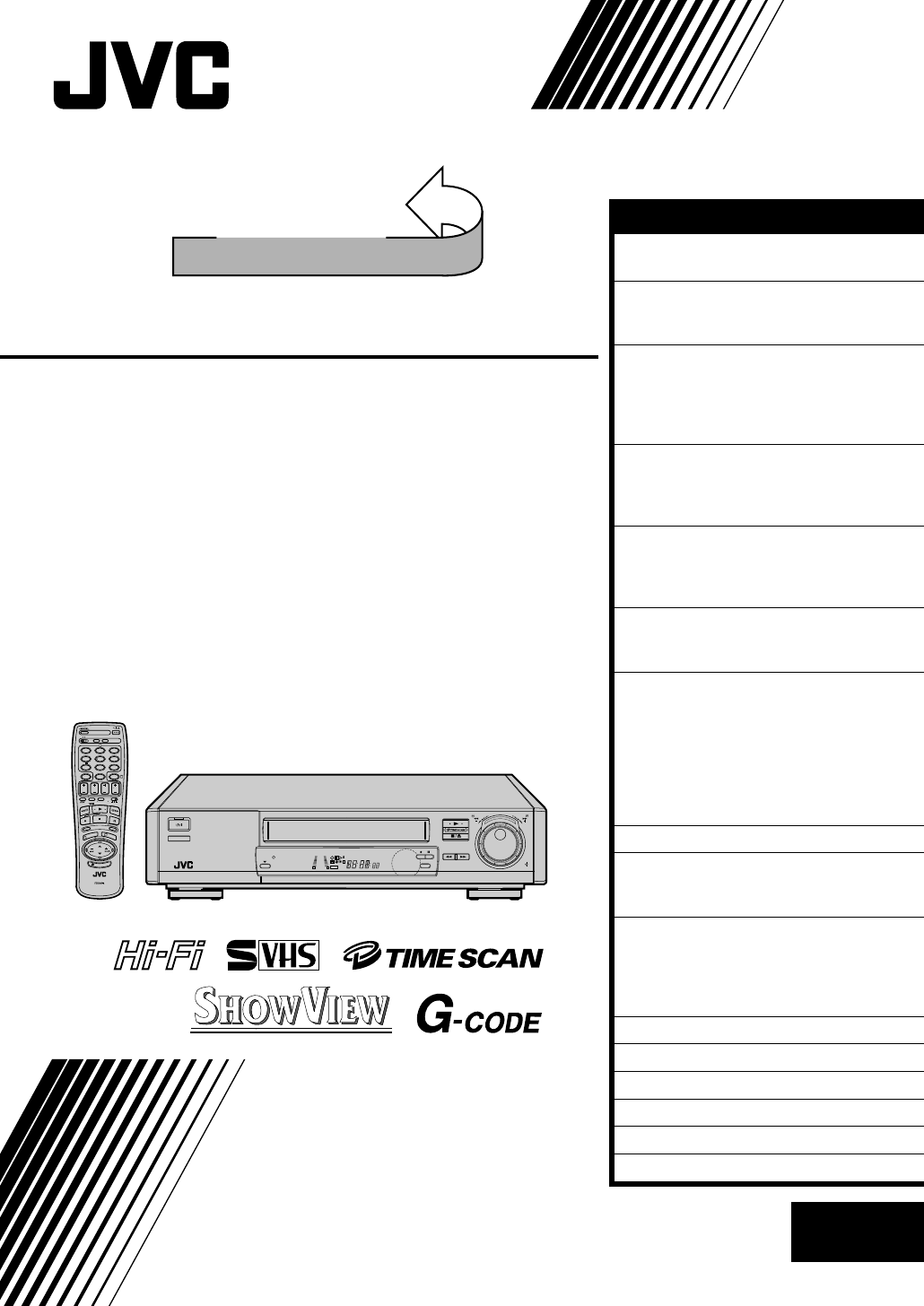
HR-S9400E/EH
VIDEO CASSETTE RECORDER
INSTRUCTIONS
LPT0002-070B
SEE
AUTO SET UP
ON REAR SIDE
SEE
AUTO SET UP
ON REAR SIDE
625
AUTO SP/LP
TIMER
TIMER
STANDBY/ON
SP/LP
8
S
L
O
W
S
L
O
W
REW FF
TV PROG/
JOG
SHUTTLE
+8
4
0
6
10
–20dB
NORM
LR
M
VCR
SP
LP
REMAIN
REVIEW
S
C
E
N
E
F
I
N
D
E
R
P
R
O
G
C
H
E
C
K
T
V
V
O
L
.
C.MEMORY DISPLAY
DAILY
AUX
ADD TIME
C.RESET
CANCEL
DATESTOP
START
AUDIO MONITOR (MONITOR)
TV/VCR TV SAT VCR
TIMER
WEEKLY
A
12
45
3
6
8
0
79
B
PUSH JOG
MULTI BRAND
REMOTE CONTROL UNIT
TV
PROG
P
R
O
G
/
M
E
N
U
O
K
EXPRESS PROGRAMMING
2
4
1
3
I
L
L
U
M
I
G
U
I
D
E
EN
CONTENTS
SAFETY FIRST 2
Safety Precautions.............................2
INSTALLING YOUR NEW RECORDER 3
Basic Connections ............................3
S-VIDEO Connection........................4
INITIAL SETTINGS 6
Auto Set Up ......................................6
Language ..........................................9
Video Channel Set ..........................10
SHOWVIEW Setup.............................12
PLAYBACK 14
Basic Playback................................14
Playback Features ...........................15
TimeScan........................................20
RECORDING 23
Basic Recording..............................23
Recording Features .........................24
On-Screen Displays ........................27
TIMER RECORDING 28
SHOWVIEW Timer Recording............28
Regular Timer Programming ...........30
EDITING 34
Preparation For Editing ...................34
Edit To Or From Another Video
Recorder.........................................36
Edit From A Camcorder ..................38
Audio Dubbing...............................39
Insert Editing...................................40
Random Assemble Editing ..............42
INFORMATION ON J TERMINAL 44
SYSTEM CONNECTIONS 45
Connecting/Using A Decoder .........45
Connecting/Using A Stereo System ...46
SPECIAL FEATURES 48
TV Multi-Brand Remote
Control ...........................................48
Satellite Tuner Multi-Brand
Remote Control ..............................49
TUNER SET 50
CLOCK SET 55
TROUBLESHOOTING 57
QUESTIONS AND ANSWERS 59
INDEX 60
SPECIFICATIONS 63
ENGLISH
2 EN
SAFETY FIRST
Failure to heed the following precautions may result in
damage to the recorder, remote control or video
cassette.
1. DO NOT place the recorder . . .
... in an environment prone to extreme temperatures or
humidity.
... in direct sunlight.
... in a dusty environment.
... in an environment where strong magnetic fields are
generated.
... on a surface that is unstable or subject to vibration.
2. DO NOT block the recorder’s ventilation openings.
3. DO NOT place heavy objects on the recorder or remote
control.
4. DO NOT place anything which might spill on top of the
recorder or remote control.
5. AVOID violent shocks to the recorder during transport.
MOISTURE CONDENSATION
Moisture in the air will condense on the recorder when you
move it from a cold place to a warm place, or under extremely
humid conditions—just as water droplets form in the surface of
a glass filled with cold liquid. Moisture condensation on the
head drum will cause damage to the tape. In conditions where
condensation may occur, keep the recorder turned on for a few
hours to let the moisture dry.
ABOUT HEAD CLEANING
Accumulation of dirt and other particles on the video heads
may cause the playback picture to become blurred or inter-
rupted. Be sure to contact your nearest JVC dealer if such
troubles occur.
IMPORTANT
nPlease read the various precautions on this page before
installing or operating the recorder.
nIt should be noted that it may be unlawful to re-record
pre-recorded tapes, records, or discs without the consent
of the owner of copyright in the sound or video record-
ing, broadcast or cable programme and in any literary,
dramatic, musical, or artistic work embodied therein.
Safety Precautions
The STANDBY/ON button does not completely shut
off mains power from the unit, but switches operating
current on and off. " " shows electrical power standby
and " " shows ON.
Video tapes recorded with this video recorder in the LP
(Long Play) mode cannot be played back on a single-speed
video recorder.
nCassettes marked "S-VHS" and "VHS" can be used with this
video cassette recorder. However, S-VHS recordings are
possible only with cassettes marked "S-VHS".
nWith this recorder, the G-Code system is identified as
"SHOWVIEW" and is operated using the "SHOWVIEW" on
screen menu.
SHOWVIEW is a registered trademark of Gemstar Development
Corporation. The SHOWVIEW system is manufactured under
licence from Gemstar Development Corporation.
G-Code is a trademark of Gemstar Development Corporation.
The G-Code system is manufactured under license from
Gemstar Development Coporation.
nCertain audio features of this product manufactured under a
license from Desper Products, Inc. Spatializert is a trademark
owned by Desper Products, Inc.
625
CAUTION
nWhen you are not using the recorder for a long period of
time, it is recommended that you disconnect the power
cord from the mains outlet.
nDangerous voltage inside. Refer internal servicing to
qualified service personnel. To prevent electric shock or
fire hazard, remove the power cord from the mains
outlet prior to connecting or disconnecting any signal
lead or aerial.
WARNING
There are two different types of SECAM colour systems:
SECAM-L, used in FRANCE (also called SECAM-West), and
SECAM-B, used in Eastern European countries (also called
SECAM-East).
1.This recorder can also receive SECAM-B colour
television signals for recording and playback.
2.Recordings made of SECAM-B television signals produce
monochrome pictures if played back on a video recorder
of SECAM-L standard, or do not produce normal colour
pictures if played back on a PAL video recorder with
SECAM-B system incorporated (even if the TV set is
SECAM-compatible).
3.SECAM-L prerecorded cassettes or recordings made with
a SECAM-L video recorder produce monochrome
pictures when played back with this recorder.
4.This recorder cannot be used for the SECAM-L standard.
Use a SECAM-L recorder to record SECAM-L signals.
For Italy:
"It is declared that this product, brand JVC, conforms to the
Ministry Decree n. 548 of 28 Aug.'95 published in the
Official Gazette of the Italian Republic n. 301 of 28 Dec.'95"
The rating plate and the safety caution are on the rear of the unit.
WARNING: DANGEROUS VOLTAGE INSIDE
WARNING: TO PREVENT FIRE OR SHOCK HAZARD, DO NOT EXPOSE THIS UNIT TO RAIN OR
MOISTURE.
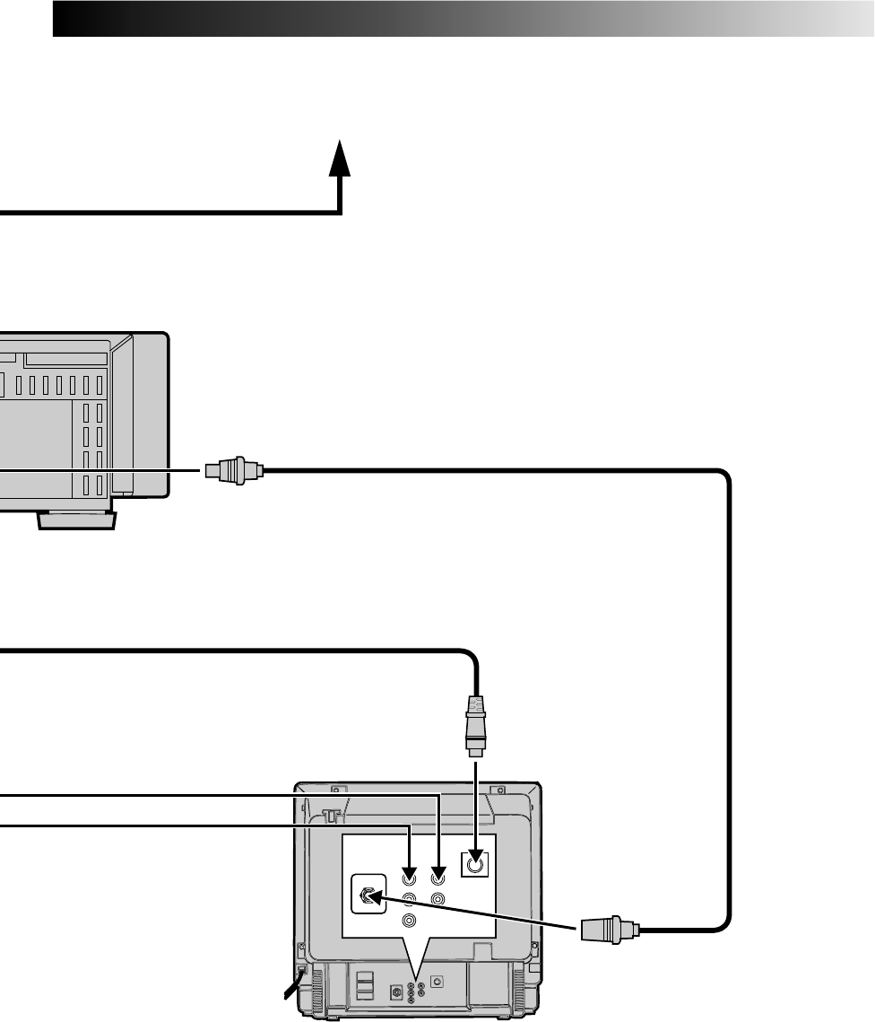
EN 3
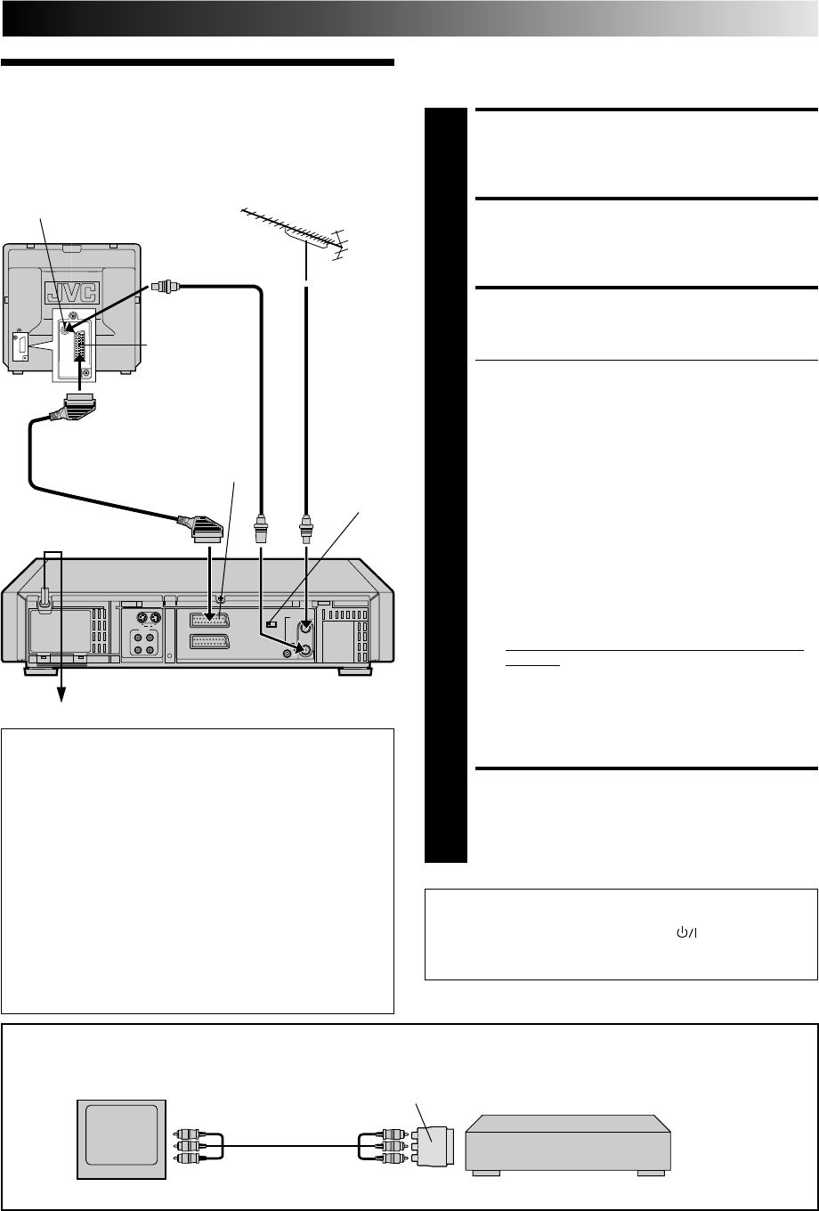
Basic
Connections
It's essential that your video recorder be properly connected.
Follow these steps carefully. THESE STEPS MUST BE COMPLETED
BEFORE ANY VIDEO OPERATION CAN BE PERFORMED.
INSTALLING YOUR NEW RECORDER
CHECK CONTENTS
1
Make sure the package contains all of the accessories
listed in “Specifications” (Z pg. 63).
SITUATE RECORDER
2
Place the recorder on a stable, horizontal surface.
CONNECT RECORDER TO TV
3
The connection method you use depends on the type of
TV you have.
RF CONNECTION
●
To Connect To A TV With NO AV Input Terminals . . .
a– Disconnect the TV aerial cable from the TV.
b– Connect the TV aerial cable to the ANT. IN jack
on the rear panel of the recorder.
c– Connect the provided RF cable between the RF
OUT jack on the rear panel of the recorder and the
TV’s aerial terminal.
Before operating the recorder, make sure the TV’s
channel is set to the VIDEO channel (Z pg. 10).
AV CONNECTION
●
To Connect To A TV With AV Input Terminals . . .
a– Connect the aerial, recorder and TV as per “RF
CONNECTION”.
b– Connect an optional SCART cable between the
AV1 IN/OUT socket on the rear panel of the
recorder and the TV’s 21-pin SCART connector.
If you are using this recorder in Australia or New
Zealand, see "For Customers in Australia and New
Zealand" on this page.
c– Choose the appropriate AV1 output signal (Z "AV1
OUTPUT SIGNAL SELECTION" on this page).
S-VIDEO CONNECTION
●
If you have a TV with S-VIDEO input terminals, see
"S-VIDEO Connection" on page 4.
CONNECT RECORDER TO MAINS
4
Plug the end of the mains power cord into a mains
outlet.
For Customers in Australia and New Zealand
Connect an optional AV cable between the TV's AV-IN terminals and the AV1 IN/OUT connector on the rear panel of the
recorder via the provided output cable adapter as illustrated.
Recorder
AV cable
(Not provided)
Output cable adapter (Provided)
To AV-IN
terminals To AV1 IN/OUT
connector
TV
AV1 OUTPUT SIGNAL SELECTION
The AV1 IN/OUT connector accepts only a composite
signal (regular video signal), but can deliver either a
composite video signal or a Y/C signal (a signal in which
the luminance and chrominance signals are separated)
according to the setting of the rear panel AV1 OUT switch.
●If your TV's SCART connector is compatible only with
the regular video signal, set this switch to COMP.
●If your TV's SCART connector is compatible with the Y/C
signal, set this switch to Y/C. You will better enjoy high-
quality S-VHS pictures.
IMPORTANT:
●Set your TV to the VIDEO (or AV), Y/C, or RGB mode
according to the type of your TV's SCART connector.
●For switching the TV's mode, refer to the instruction
manual of your television.
AV1 IN/OUT
21-pin SCART
connector
Mains Power Cord
Aerial terminal
Back of TV
RF Cable
(provided)
AV1 OUT
switch
TV Aerial
Cable
21-pin
SCART
Cable
Rear view
Mains outlet
After you plug the mains power cord into a mains outlet, the
Country Set display appears on the TV screen and/or on the
recorder's front display panel when the button on the
recorder/remote control is pressed for the first time to power
on the recorder; go to page 6 to perform Auto Set Up.
4 EN
AV1 IN/OUT
RF OUT
AV2 IN/DECODER
PAUSE/
R.A.EDIT
AV1 OUT
ANT.IN
COMP.
Y/C
RR
LL
AUDIO
S
IN
IN
OUT
OUT
INSTALLING YOUR NEW RECORDER (cont.)
CONNECT RECORDER TO
TV
1
a– Connect the aerial, recorder and TV as per "Basic
Connections" (Z pg. 3).
b–Connect the recorder's S OUT terminal to the TV's S-
VIDEO IN terminal.
c–Connect the recorder's AUDIO OUT terminals to the
TV's AUDIO IN terminals.
CONNECT RECORDER TO
MAINS
2
Plug the end of the mains power cord into a mains
outlet.
For TV sets with an S-VIDEO input terminal:
S-VIDEO Connection
IMPORTANT:
To operate the recorder with your TV using the S-VIDEO
connection, set your TV to the VIDEO (or AV mode).
AUDIO OUT
Mains outlet
Mains Power Cord
Audio cable (provided)
ANT.IN
RF OUT
S OUT
After you plug the mains power cord into a mains outlet, the
Country Set display appears on the TV screen and/or on the
recorder's front display panel when the button on the
recorder/remote control is pressed for the first time to power
on the recorder; go to page 6 to perform Auto Set Up.
NOTE:
If your television is not stereo-capable, use the recorder's
AUDIO OUT connectors to connect to an audio amplifier for
Hi-Fi stereo sound reproduction. (
Z
pg. 46)
EN 5
Rear view
RF Cable (provided)
Aerial or Cable
Back of TV
S-Video cable (provided)
6 EN
INITIAL SETTINGS
When the button on the recorder/remote control is pressed
for the first time to power on the recorder after you plug the
mains power cord into a mains outlet, the Country Set display
will appear on the TV screen and the recorder's front display
panel. By simply selecting your country*, the Auto Set Up
function sets the tuner channels, clock and Guide Program
numbers automatically.
*If you live in Belgium or Switzerland, you also need to select the
language you use.
You can refer to the front display panel and/or the on-screen
display to perform this procedure.
Before starting, make sure of the following:
●The TV aerial cable should be connected to the recorder.
●The recorder's mains power cord should be connected to
a mains outlet. Z pg. 3
●If you want to use the on-screen display, the TV should
be set to its AV mode (with AV or S-VIDEO connection
Z pg. 3 or 4) or UHF channel 36 (with RF connection
Z pg. 3).
Auto Set Up
Auto Channel Set/Auto
Clock Set/Auto Guide
Program Number Set
ATTENTION
Once you have performed Auto Set Up, even if the
recorder's memory backup has expired, all the stored
stations and their Guide Program numbers remain in the
recorder's memory and the recorder will not perform Auto
Set Up again. You only need to set the clock. (Z pg. 55)
If you have moved to a different area, perform each setting
as required.
● Tuner setting Z pg. 50
●Clock setting Z pg. 55
●SHOWVIEW Guide Program number setting Z pg. 12
If a new station starts broadcasting in your area, perform
both tuner setting (Z pg. 50) and SHOWVIEW Guide
Program number setting (Z pg. 12).
12
45
3
6
8
0
79
2
4
1
3
PUSH JOG
OK
International Telephone Country Code
SUOMI : 358 SUISSE : 41
PORTUGAL : 351 ITALIA : 39
DEUTSCHLAND : 49 ESPAÑA : 34
NORGE : 47 BELGIUM : 32
SVERIGE : 46 NEDERLAND : 31
DANMARK : 45 GREECE : 30
ÖSTERREICH : 43 OTHERS : - -
* Depending on the model, the selectable codes
may be limited.
8
••
•
•
••
••
••
•
••
•
•
••
••
••
•
CONTINUED ON NEXT PAGE.
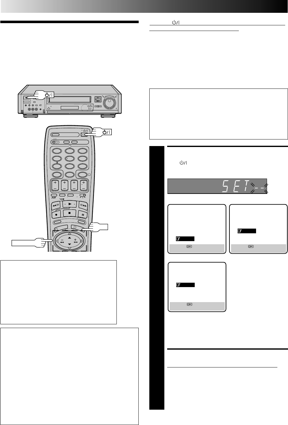
TURN ON THE RECORDER
1
Press on the recorder or remote control. The
Country Set display appears on the front display panel
and/or on the screen.
NOTE:
If you have connected your TV to the recorder with RF
connection and the on-screen display appearing on
UHF channel 36 looks distorted, perform this procedure
referring to the front display panel.
SELECT COUNTRY
2
If you are referring to the front display panel
Press PUSH JOG%fi to select your international
telephone country code of your country referring to the
chart in the left column.
● If you have selected a country code other than 32
(BELGIUM) or 41 (SUISSE), go to step 4.
● If you have selected 32 (BELGIUM) or 41 (SUISSE), go
to step 3.
SUOMI
NORGE
SVERIGE
DANMARK
OTHERS
[5∞] =
[MENU] : EXIT
For HR-S9400E For HR-S9400EH
* The on-screen display
differs for the HR-
S9400EH depending
upon the country in
which the product was
purchased.
PORTUGAL
ESPAÑA
BELGIUM
OTHERS
[5∞] =
[MENU] : EXIT
For HR-S9400EH
DEUTSCHLAND
ÖSTERREICH
SUISSE
ITALIA
NEDERLAND
GREECE
OTHERS
[5∞] =
[MENU] : EXIT
EN 7
If you are referring to the on-screen display
Press PUSH JOG%fi to move the highlight bar
(pointer) to your country's name.
● If you have selected a country other than BELGIUM
or SUISSE, go to step 4.
● If you have selected BELGIUM or SUISSE, go to step 3.
SELECT LANGUAGE
3
Press OK. the Language Set display appears on the front
display panel and/or on the screen.
If you are referring to the front display panel
Press PUSH JOG%fi to select your language code
referring to the chart in the left column.
If you are referring to the on-screen display
Press PUSH JOG%fi to move the highlight bar (pointer)
to the language of your choice.
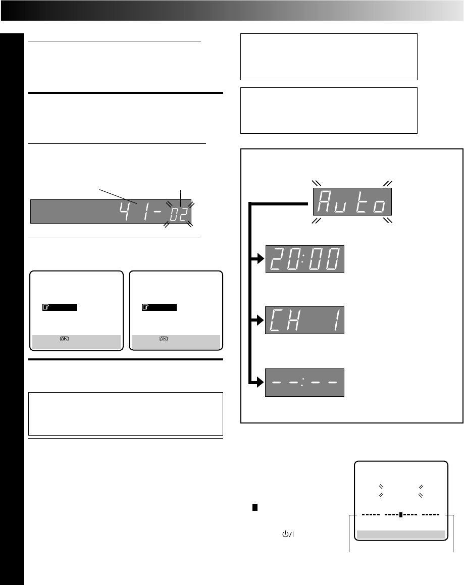
PERFORM AUTO SET UP
4
Press OK.
"Auto" appears on the display panel and blinks; do
NOT press any button on the recorder or remote
control until the display panel shows the current
time or "CH1" or "--:--". (Refer to box on this page.)
●Auto channel set function takes place first; it assigns
automatically all receivable stations in your area.
●Auto clock set function sets the clock automatically
by reading the clock setting data from a station
transmitting a PDC signal while auto channel set is
being performed.
●During auto channel set, the recorder recognizes each
station name of the detected stations and stores them
in the recorder's memory, then automatically sets
SHOWVIEW assigned Guide Program number for those
stations according to the broadcast area.
NOTE:
In the area where no TV station transmits a PDC signal,
the recorder can perform neither auto clock set nor
auto Guide Program number set.
(Ex.) DEUTSCH is selected for SUISSE
International telephone
country code Language code
For HR-S9400E For HR-S9400EH
Language Code for the HR-S9400E
ENGLISH : 01 ITALIANO : 04
DEUTSCH : 02 NEDERLANDS : 05
FRANCAIS : 03
Language Code for the HR-S9400EH
ENGLISH : 01 CASTELLANO : 04
DEUTSCH : 02 NEDERLANDS : 05
FRANCAIS : 03
●When auto channel set has
been completed success-
fully but auto clock set has
not, "CH" will be displayed.
●When neither auto
channel set nor auto clock
set has been completed
successfully, "--:--" will be
displayed.
●When both auto channel
set and auto clock set have
been completed success-
fully the correct current
time will be displayed.
● If Auto Set Up is completed, go to page 8.
Auto Set Up results appear on the front
display panel
NOTES:
●
If you are using the on-
screen display, the AUTO
SET screen will appear after
pressing OK in step 4. As
Auto Set Up progresses, the
" " mark on the screen
moves from left to right.
●
If there is a power cut, or if
you press or MENU
while Auto Set Up is in
progress, Auto Set Up will
be interrupted; be sure to
turn off the recorder power once and try again from step 1.
AUTO SET
PLEASE WAIT
[MENU] : EXIT
0
+++
Beginning End
NEDERLANDS
ITALIANO
FRANCAIS
DEUTSCH
ENGLISH
[5∞] =
[MENU] : ENDE
NEDERLANDS
CASTELLANO
FRANCAIS
DEUTSCH
ENGLISH
[5∞] =
[MENU] : ENDE

8 EN
INITIAL SETTINGS (cont.)
If both auto channel set and auto clock set have been performed successfully:
1Perform "Video Channel Set" on page 10.
2Turn on the TV and select its VIDEO channel or AV mode, then make sure that all necessary stations have been stored in the
recorder's memory by using the TV PROG button(s).
●If station names (ID — Z pg. 54) have also been stored in the recorder's memory, the station name will be displayed at the
top left corner of the screen for about 5 seconds when the recorder is tuned to a different station.
●If you want to set the tuner manually such as to add or skip channels, to change channel positions, or to set or change
station names, see pages 52 – 53.
3Perform "SHOWVIEW Setup" on page 12 to check if the Guide Program numbers have been set correctly.
If auto channel set has succeeded but auto clock set has not:
1Perform "Video Channel Set" on page 10.
2Turn on the TV and select its VIDEO channel or AV mode, then make sure that all necessary stations have been stored in the
recorder's memory by using the TV PROG button(s).
●If station names (ID — Z pg. 54) have also been stored in the recorder's memory, the station name will be displayed at the
top left corner of the screen for about 5 seconds when the recorder is tuned to a different station.
●If you want to set the tuner manually such as to add or skip channels, to change channel positions, or to set or change
station names, see pages 52 – 53.
3Perform "Clock Set" on page 55, then "SHOWVIEW Setup" on page 12 to check if the Guide Program numbers have been set
correctly.
If both auto channel set and auto clock set have failed:
1Make sure the TV aerial cable is connected properly to the recorder and turn off the recorder power once, then turn the
recorder power back on again.
●The Country Set display appears on the front display panel and/or on the screen; perform steps 2 and 4 on pages 6 – 7
again.
IMPORTANT
● Depending on the reception conditions, the station names may not be stored correctly, and auto Guide Program Number Set may
not work properly. If the Guide Program numbers are not set properly, SHOWVIEW timer recording (Z pg. 28) will not work
correctly; be sure to check if the Guide Program numbers have been set correctly (Z pg. 12, "SHOWVIEW Setup").
●Since your video recorder memorizes all detected stations even if the reception condition is poor, some of those stored stations
may produce a noisy picture. To delete those stations, Z "Delete A Channel" on page 52.
INFORMATION
Language for the on-screen display
Auto Set Up also selects the language automatically for the on-screen display depending on the Country setting you have made
in step 2 on page 6 (unless you have selected BELGIUM or SUISSE), as shown below.
SUOMI [SUOMI SVERIGE [SVENSKA ESPAÑA [CASTELLANO
PORTUGAL [ENGLISH DANMARK [DANSK NEDERLAND [NEDERLANDS
DEUTSCHLAND [DEUTSCH ÖSTERREICH [DEUTSCH GREECE [ENGLISH
NORGE [NORSK ITALIA [ITALIANO OTHERS [ENGLISH
If you want to change the language setting manually, Z "Language" on page 9.
Just Clock
Your recorder is equipped with the Just Clock function which provides accurate time keeping through automatic adjustments at
regular intervals, by reading data from a PDC signal. If you want to take advantage of this function, simply set it to "ON".
Z "Just Clock" on page 55.
EN 9
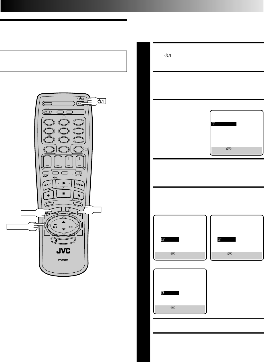
Language This recorder offers you the choice to view on-screen messages
in 10 different languages. Though Auto Set Up selects the
language automatically (Z pg. 8), you can change the language
setting manually using this procedure as required.
TURN ON THE RECORDER
1
Press .
ACCESS MAIN MENU
2
Press MENU twice.
ACCESS COUNTRY SET SCREEN
3
Press PUSH JOG%fi to
move the highlight bar
(pointer) to "AUTO CH
SET", then press OK.
SELECT COUNTRY
4
Press PUSH JOG%fi to move the highlight bar (pointer)
to your country's name, then press OK. The Language
Set screen appears.
SELECT LANGUAGE
5
Press PUSH JOG%fi to move the highlight bar (pointer)
to the language of your choice.
●You do not have to press OK; pressing OK starts Auto
Channel Set.
RETURN TO NORMAL SCREEN
6
Press MENU.
●Be sure to set your Video Channel before performing
Language setting (Z pg. 10).
●Turn on the TV and select the VIDEO channel (or AV mode).
12
45
3
6
8
0
79
2
4
1
3
PUSH JOG
MENU OK
MAIN MENU
MODE SET
AUTO CH SET
MANUAL CH SET
GUIDE PROG SETT
CLOCK SET
JLIP ID NO. SET
R.A. EDIT
[5∞] =
[MENU] : EXIT
For HR-S9400EH For HR-S9400EH
* The on-screen display
differs for the HR-
S9400EH depending
upon the country in
which the product was
purchased.
DANSK
SUOMI
NORSK
SVENSKA
ENGLISH
[5∞] =
[MENU] : EXIT
NEDERLANDS
CASTELLANO
FRANCAIS
DEUTSCH
ENGLISH
[5∞] =
[MENU] : EXIT
NEDERLANDS
ITALIANO
FRANCAIS
DEUTSCH
ENGLISH
[5∞] =
[MENU] : EXIT
For HR-S9400E
10 EN
Video
Channel Set
INITIAL SETTINGS (cont.)
Video Channel (RF Output Channel) is the channel on
which your TV receives picture and sound signals from the
video recorder through the RF cable.
8
••
•
•
••
••
••
•
••
•
•
••
••
••
•
12
45
3
6
8
0
79
2
4
1
3
OK
If you have connected the video recorder to your TV
via the provided RF cable only (RF connection) – Go to
"With RF Connection" below.
If you have connected the video recorder to your TV
via both the provided RF cable and a 21-pin SCART
cable (AV connection) or via the provided RF cable, the
provided S-Video cable and the provided audio cable
(S-VIDEO connection) – Go to "With AV or S-VIDEO
Connection" on next page.
TEST SIGNAL
The channel on which the screen to
the left appear clearly in step 2 is
your Video Channel.
To view picture signals from the video recorder, set
your TV to the Video Channel.
STOP
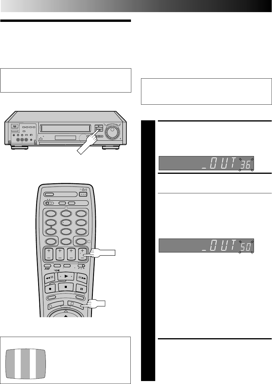
TV PROG
ACCESS VIDEO CHANNEL
SET MODE
1
Hold down STOP on the recorder until the display
panel shows the following.
SET VIDEO CHANNEL
2
Set your TV to UHF channel 36.
●If the two vertical white bars appear clearly on the
screen as shown in the illustration at bottom left, go
to step 3.
●If the two vertical white bars do not appear clearly,
press TV PROG + or – to set the video recorder to a
vacant channel between 22 and 69 which is not
occupied by any local station in your area.
Then set your TV to UHF channel 50 and check if the
two vertical white bars appear clearly on the screen; if
so, go to step 3. If not, re-set the video recorder to
another vacant channel and try again.
NOTES:
●
If you set the video recorder to a channel which is
occupied by a local station or has neighbouring
channels that are occupied by local stations, the
picture reception quality will be affected and some
interference noise will appear on the TV screen. Be
sure to select a vacant channel which has no
broadcast on neighbouring channels.
●
If you cannot obtain the two vertical white bars
clearly with any channel between 22 and 69, consult
your JVC dealer.
EXIT VIDEO CHANNEL SET
MODE
3
Press OK.
With RF Connection
(Ex.) If channel 50 is available in your area
IMPORTANT:
Before performing the following steps, make sure the
recorder's power is off and there is no cassette inserted in
the recorder.
EN 11
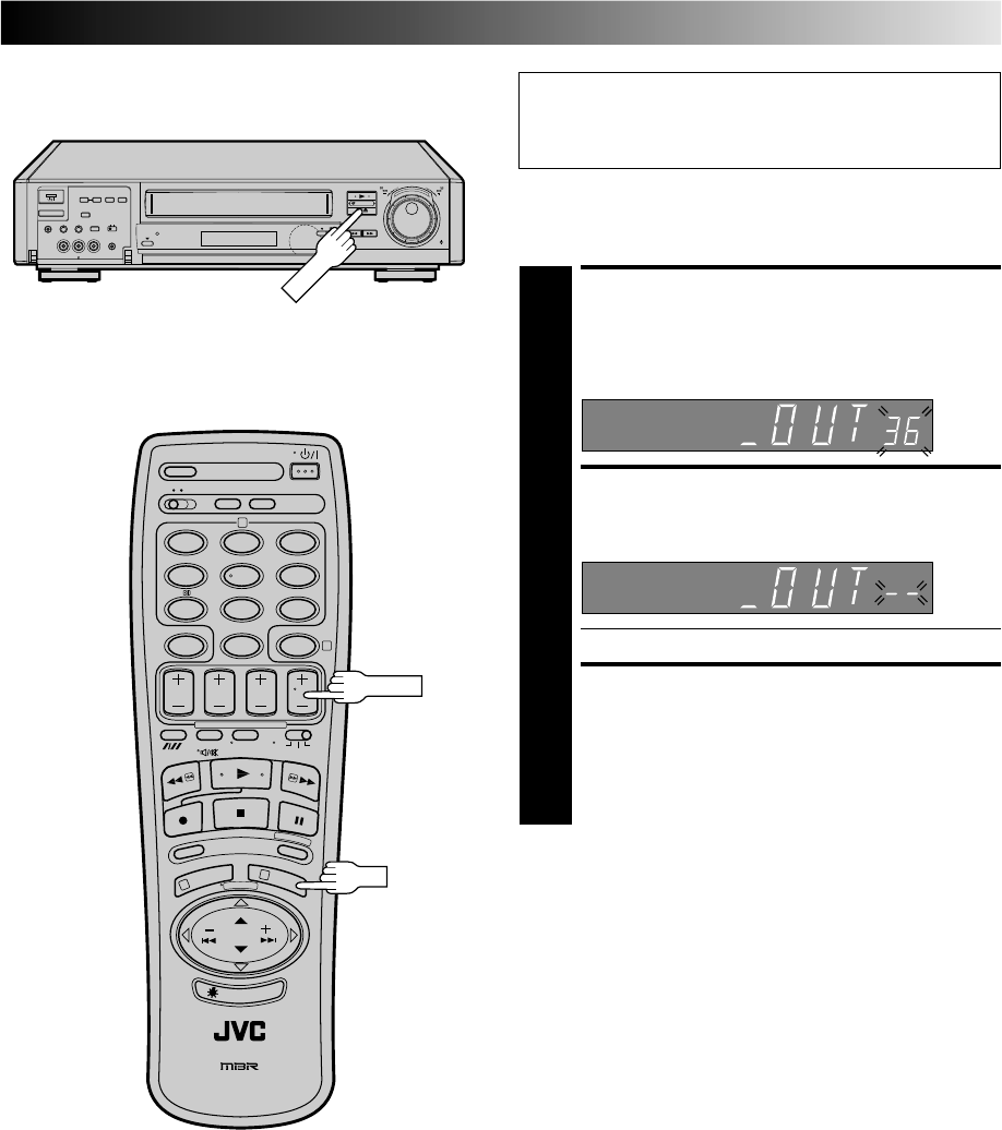
IMPORTANT:
Before performing the following steps, make sure the
recorder's power is off and there is no cassette inserted in
the recorder.
With AV Or S-VIDEO
Connection
8
••
•
•
••
••
••
•
••
•
•
••
••
••
•
12
45
3
6
8
0
79
2
4
1
3
OK
STOP
TV PROG
ACCESS VIDEO CHANNEL
SET MODE
1
Hold down STOP on the recorder until the display
panel shows the following.
SET VIDEO CHANNEL
2
Press TV PROG – until the display panel shows
"–OUT– –".
●Now the video channel is set to off.
EXIT VIDEO CHANNEL SET
MODE
3
Press OK.
To view picture signals from the video recorder, set
your TV to its AV mode.
12 EN
INITIAL SETTINGS (cont.)
SHOWVIEW
Setup
With SHOWVIEW, timer programming is greatly simplified
because each TV programme has a corresponding code number
which your recorder is able to recognise.
NOTE:
“Guide Program (GUIDE PROG) Number” refers to the assigned
TV station numbers, according to broadcast area, for S
HOW
V
IEW
timer recording.
IMPORTANT
Perform the following procedure after Auto Set Up on page 6
and/or the channel setting steps on pages 50 – 53, and after the
Clock Set procedure on page 55.
After setting the Guide Program Numbers, the station names and
channel positions may be incorrect if you stored or skipped
channels. In this case, re-perform Guide Program Number setting.
Turn on the TV and select the VIDEO channel (or AV mode).
MAKE LIST OF STORED
STATION NAMES AND
CHANNEL POSITIONS
1
(Ex.)
ACCESS MAIN MENU
SCREEN
2
Press MENU twice.
ACCESS GUIDE PROG SET
SCREEN
3
Press PUSH JOG %fi to move the highlight bar
(pointer) to "GUIDE PROG SET", then press OK.
The Guide Prog. Set screen appears.
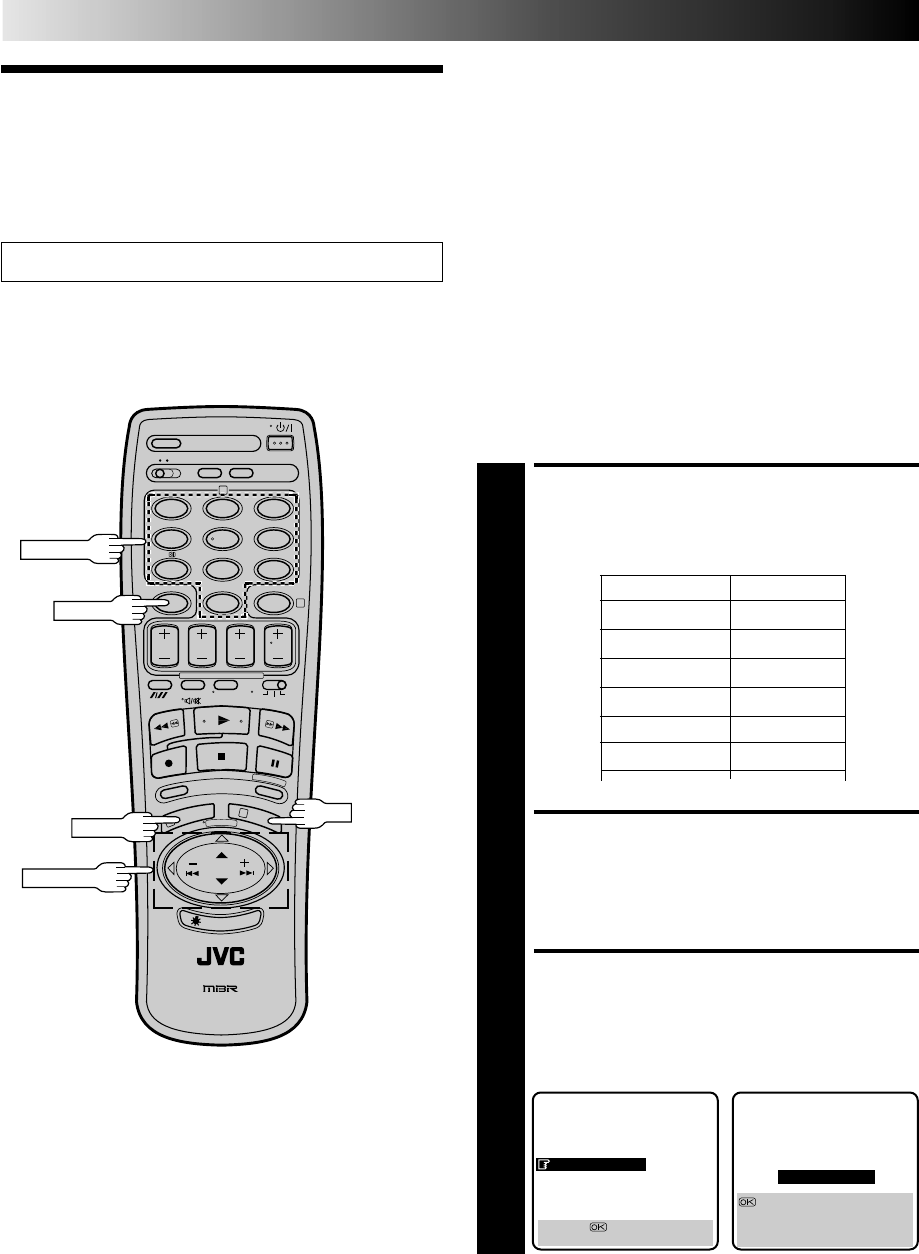
Channel position Station name
1 ARD
2 ZDF
3 WDR
Guide Program Number Set
MAIN MENU
MODE SET
AUTO CH SET
MANUAL CH SET
GUIDE PROG SET
CLOCK SET
JLIP ID NO. SET
R.A. EDIT
[5∞] =
[MENU] : EXIT
5
GUIDE PROG SET
GUIDE PROG TV PROG
11
: AUTO SET BY SHOWVIEW
[ ]: MANUAL SET
[5∞] : ?
[MENU] : EXIT
* For Customers in Australia and New Zealand:
With this recorder, the G-Code system is identified as
"SHOWVIEW".
12
45
3
6
8
0
79
2
4
1
3
NUMBER
OK
CANCEL
PUSH JOG
MENU

EN 13
ENTER SHOWVIEW
NUMBER
4
Press OK, and a cursor
appears above “GUIDE
PROG”. Then, using the
NUMBER keys, input the
SHOWVIEW number (found
in most TV listings) of a
program scheduled to be
broadcast on each station
on the list from step 1,
starting at the top. If you
enter the wrong number,
press CANCEL to backspace
and input the correct number.
CONFIRM CHANNEL
POSITION NUMBER
4
5
Press OK and the display
under “TV PROG” begins
blinking.
If the blinking number
under “TV PROG” agrees
with the channel
position . . .
. . . press OK.
If the numbers do not
agree . . .
. . . input the channel position using PUSH JOG%fi or
the NUMBER keys, then press OK.
●If you input the SHOWVIEW number of a program that
has already aired, “ERROR” appears on screen for a
few seconds. Input the correct SHOWVIEW number.
●Repeat steps 4 and 5 as necessary.
CLOSE MENU
6
Press MENU and selection is complete.
If you already know the Guide Program number for a station . . .
1– After step 3, press PUSH JOG .
●The GUIDE PROG number begins blinking.
2– Enter the Guide Program number using the NUMBER keys
or PUSH JOG%fi, then press PUSH JOG .
●The TV PROG number begins blinking.
3– Enter the channel position using the NUMBER keys or
PUSH JOG%fi, then press PUSH JOG .
●Repeat 2 and 3 as necessary.
4– Press MENU.
When Using A Satellite
Tuner
Preparation
1– Connect the satellite tuner to the AV2 IN/DECODER
connector on the rear of your recorder.
2– Set "AV2 SELECT" to "AV2" (Z pg. 35).
To Record Satellite Broadcasts . . .
1– Select the appropriate channel on the satellite tuner.
2– Set your recorder's input mode to "AUX2". (Z pg. 35)
3– Start recording (Z pg. 23, steps 3 – 6).
To Record Satellite Broadcasts Using SHOWVIEW Timer
Recording . . .
1– Set your recorder's input mode to "AUX2". (Z pg. 35)
2– Perform Guide Program Number setting.
●In step 5 in the left column, press NUMBER key "0" to set
"TV PROG" to "AUX2".
3– Perform SHOWVIEW Timer Recording (Z pg. 28).
To Record Satellite Broadcasts Using Regular Timer Recording . . .
1– In step 6 on page 31, press TV PROG +/– to set the channel
position to "AUX2".
NOTES:
●
When timer-recording a satellite programme, first set the
satellite tuner to the appropriate channel before the selected
programme begins and then set the satellite tuner's timer. If
your satellite tuner does not have a timer, leave it switched on.
●
If your recorder's front panel VIDEO and/or AUDIO connec-
tors are being used, they take priority and "AUX2" cannot be
selected. Make sure no cables are connected to the front
panel connectors when performing this procedure.
GUIDE PROG SET
12345
GUIDE PROG TV PROG
11
[0-9] =
[MENU] : EXIT
When entering a S
HOW
V
IEW
number for ZDF
%
%
%
GUIDE PROG SET
GUIDE PROG TV PROG
22
[5∞] =
[MENU] : EXIT
Satellite Antenna
Ex. 1 Ex. 2
Satellite
Tuner and
Decoder
TV Receiver
AV2 IN/
DECODER
For Customers in
Australia and
New Zealand:
When connecting
the AV cable, use
the input and/or
output cable
adapter.
Rear view
Satellite
Tuner
Aerial or Cable
14 EN
PLAYBACK
Basic
Playback
The easiest, most basic operation possible with your video
recorder is tape playback. Already-recorded signals on a video
tape are read by your video recorder and displayed on your TV
just like a TV programme.
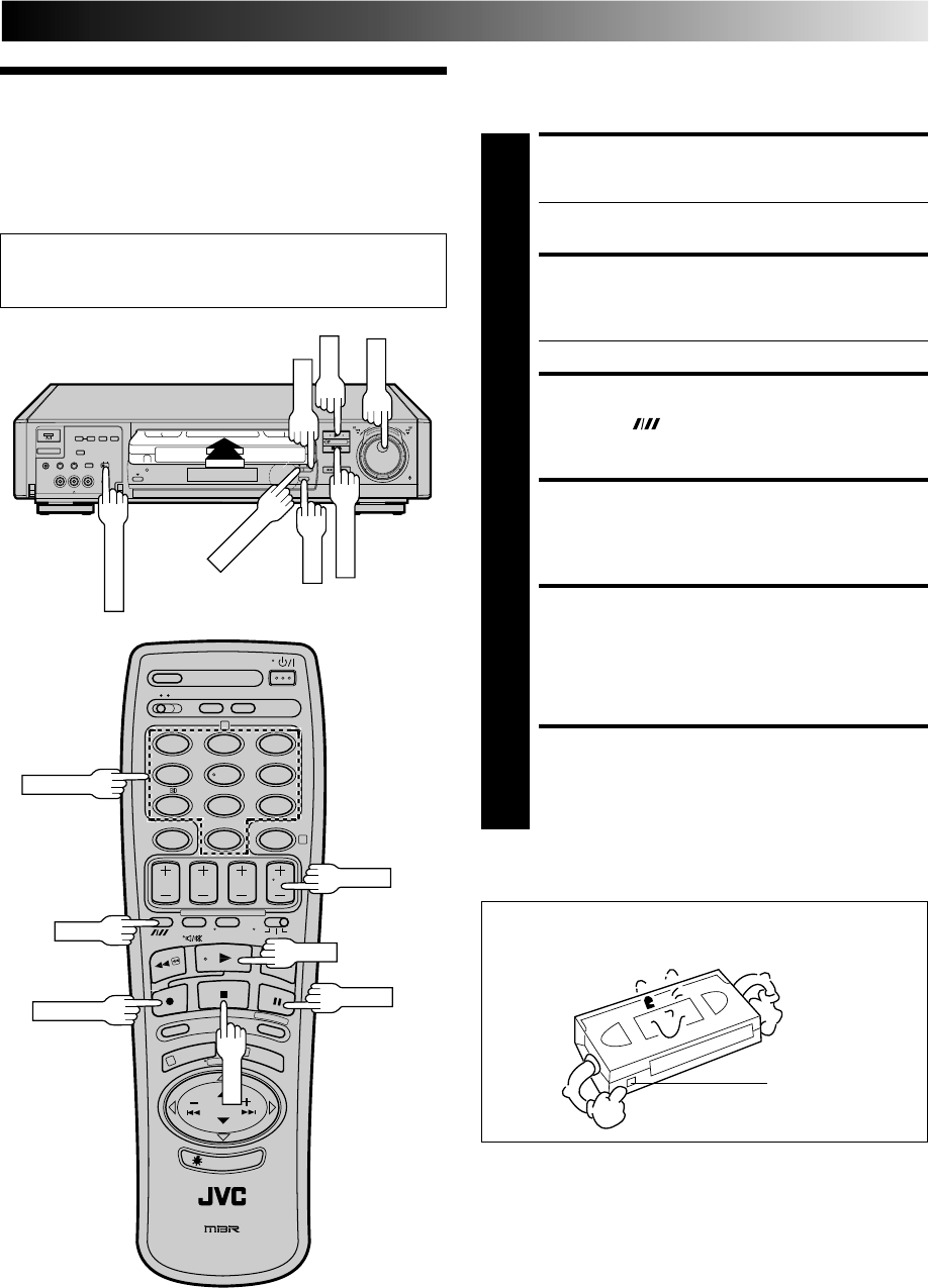
LOAD A CASSETTE
1
Make sure the window side is up, the rear label side is
facing you and the arrow on the front of the cassette is
point toward the recorder. Don’t apply too much
pressure when inserting.
●The recorder power comes on automatically and the
counter is reset to 0:00:00.
●If the record safety tab has been removed, playback
begins automatically.
FIND PROGRAMME START
POINT
2
If the tape is advanced past the start point, press REW or
turn the TIME SCAN SHUTTLE ring to the left.
To go forward, press FF or turn the TIME SCAN
SHUTTLE ring to the right.
START PLAYBACK
3
Press PLAY.
STOP PLAYBACK
4
Press STOP on the remote or STOP/EJECT on the
recorder’s front panel. Then press STOP/EJECT to
remove the cassette.
12
45
3
6
8
0
79
2
4
1
3
REW FF
PLAY
●Turn on the TV and select the VIDEO channel (or AV mode).
●Set the PAL/MESECAM switch to the appropriate position.
Z pg. 16
STOP
8
••
•
•
••
••
••
•
••
•
•
••
••
••
•
Usable cassettes
PLAY
STOP/EJECT
REW
FF
TIME SCAN SHUTTLE
PAL/MESECAM
●Compact VHS camcorder recordings can be played on
this video recorder. Simply place the recorded cassette
into a VHS Cassette Adapter and it can be used just like
any full-sized VHS cassette.
●This video recorder can record on regular VHS and
Super VHS cassettes. While only VHS signals can be
recorded on regular VHS cassettes, both VHS and Super
VHS signals can be recorded and played back using
Super VHS cassettes.
EN 15
Playback
Features
High-Speed (Turbo) Search
ACTIVATE HIGH-SPEED
SEARCH
1
During playback or still picture, press FF for forward
high-speed search, or REW for reverse high-speed
search.
To resume normal playback, press PLAY.
NOTES:
●
For short searches, press and hold FF or REW for over 2
seconds. When released, normal playback resumes.
●
Picture may not appear during search with an LP-recorded
tape.
●
In the search, still, or frame by frame playback mode, the
picture may be distorted, and there may be a loss of colour.
Still Picture/Frame-By-Frame
Playback
PAUSE DURING PLAYBACK
1
Press PAUSE. If there is vertical jitter, use the TV PROG
buttons to correct the picture.
●During still picture, the sound from the previous
3 seconds (approx.) will be played back repeatedly
(provided there was at least 6 seconds of normal
playback prior to engaging the still picture mode).
However, the TIME SCAN indicator will not light.
●"TIME SCAN AUDIO" must be set to "ON", or the
sound will not be heard. (Z pg. 22)
ACTIVATE FRAME-BY-FRAME
PLAYBACK
2
Turn the JOG dial to the right for forward frame-by-
frame playback, or to the left for reverse frame-by-frame
playback.
OR
Press PAUSE.
OR
Press PUSH JOG or .
To resume normal playback, press PLAY.
%
%
Take advantage of special functions possible with the recorder’s
controls or the remote control.
Slow Motion
ACTIVATE SLOW-MOTION
PLAYBACK
1
Turn the TIME SCAN SHUTTLE ring to the left or press
PUSH JOG during playback to decrease speed in the
forward direction. To play in reverse slow-motion (and
in reverse play mode), continue to turn the TIME SCAN
SHUTTLE ring to the left or press PUSH JOG after
selecting all the forward direction slow-motion modes.
OR
During still picture, turn the TIME SCAN SHUTTLE ring
to the right for forward slow motion, or to the left for
reverse slow motion.
OR
During still picture, press and hold PAUSE for 2
seconds, then release. Press and release again to return
to still picture.
OR
During still picture, press and hold PUSH JOG or .
Release to return to still picture.
To resume normal playback, press PLAY.
%
fi
%
%
8
••
•
•
••
••
••
•
••
•
•
••
••
••
•
0
4
1
3
PAUSE
PLAY
PUSH JOG
REW FF
TIME SCAN SHUTTLE
REW
FF
JOG
PAUSE
PLAY
TV PROG
16 EN
Manual Tracking
Your video recorder is equipped with automatic tracking
control. During playback, you can override this and adjust the
tracking manually by pressing the TV PROG buttons.
OVERRIDE AUTOMATIC
TRACKING
1
Press SP/LP ( ) on the remote to engage manual
tracking.
ADJUST TRACKING
MANUALLY
2
Press TV PROG + or – to adjust tracking.
RETURN TO AUTOMATIC
TRACKING
3
Press SP/LP ( ) on the remote to re-engage auto-
matic tracking.
NOTE:
When a new tape is inserted, the recorder enters the automatic
tracking mode automatically.
PLAYBACK (cont.)
8
••
•
•
••
••
••
•
••
•
•
••
••
••
•
12
45
3
6
8
0
79
2
4
1
3
REW FF
REVIEW
PUSH JOG
REW
FF
PAL/MESECAM
TV PROG
Colour System Selection
You can also record SECAM signals, or play back a MESECAM
tape on this recorder.
* MESECAM is the designation for tapes with SECAM signals
that have been recorded on a MESECAM-compatible PAL
video recorder.
●To record SECAM signals or play back a MESECAM tape, set
the PAL/MESECAM switch to "MESECAM".
●To record PAL signals or play back a PAL tape, set the PAL/
MESECAM switch to "PAL".
3R Picture
Your video recorder is equipped with the 3R Picture System.
During playback, 3R(= Resolution and Response Recovery
technology) maximises sense of resolution and sharpens image
edges to make playback picture look better focused.
EN 17
Index Search
Your recorder automatically marks
index codes at the beginning of
each recording. This function gives
you quick access to any one of 9
index codes in either direction.
NOTE:
Before starting, make sure the
recorder is in the Stop mode.
ACTIVATE INDEX SEARCH
1
Press PUSH JOG or (™ or £). “™ 1” or
“£ 1” is displayed on screen and search begins in
the corresponding direction.
●To access index codes 2 through 9, press PUSH JOG
or repeatedly until the correct index number is
displayed.
Ex.: To locate the beginning of B from the current
position, press PUSH JOG twice.
To locate the beginning of D from the current
position, press PUSH JOG once.
●When the specified index code is located, playback
begins automatically.
Current position
Index number
%
fi
%
fi
fi%
AB C D E F
–2 –1 1 2 3
%
%
£2
Instant ReView
Simply by pressing a single button, the recorder power comes
on, rewinds, and begins playback of the last timer-recorded
programme. If you have several programmes recorded, you can
easily access any of them.
NOTE:
Before starting, make sure that the recorder is off and that the
Timer mode is disengaged.
ACTIVATE INSTANT
REVIEW
1
Press REVIEW. The recorder power comes on and the
recorder searches for the index code indicating the start
of the last timer-recorded programme. Once it’s found,
playback begins automatically.
The front display panel tells you how many programmes
have been recorded. If you have, for example, 3
programmes, “REVIEW” and "3" appear and blink. To
watch the first of the 3 programmes, press REVIEW three
times. The recorder searches and begins playback
automatically. You can access a programme as far as 9
index codes away from the current tape position.
NOTE:
Instant ReView is not possible while the recorder is in the Timer
mode.
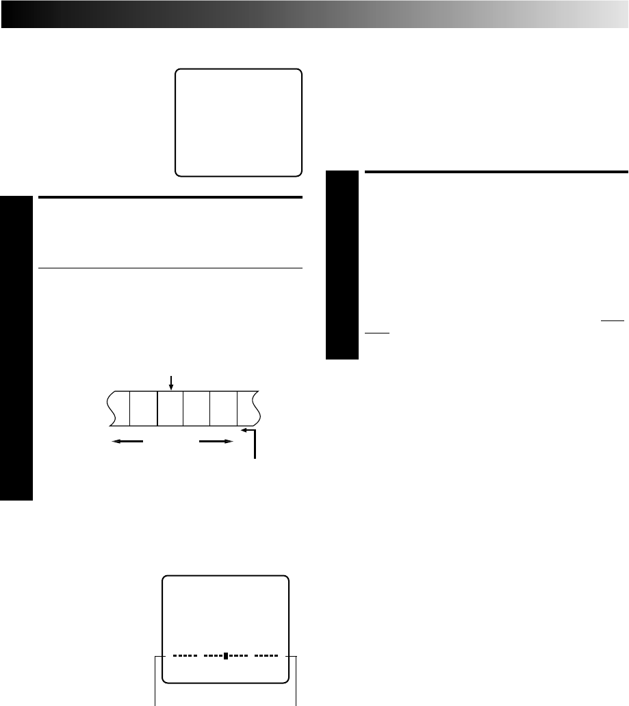
Tape Position Indicator
The tape position indicator
appears on screen when, from
the Stop mode, you press FF,
REW or perform an Index
Search. The position of “5” in
relation to “0” (beginning) or
“+” (end) shows you where you
are on the tape.
”O.S.D.” (Z pg. 27) must be
set to “ON”, or the indicator
will not appear.
NOTE:
Depending on the type of tape used, there may be times when
the indication is not correct.
3
1:23:45
REMAIN 2:35
0
+++
Beginning End
18 EN
PLAYBACK (cont.)
SpatializerW
Soundtrack Selection
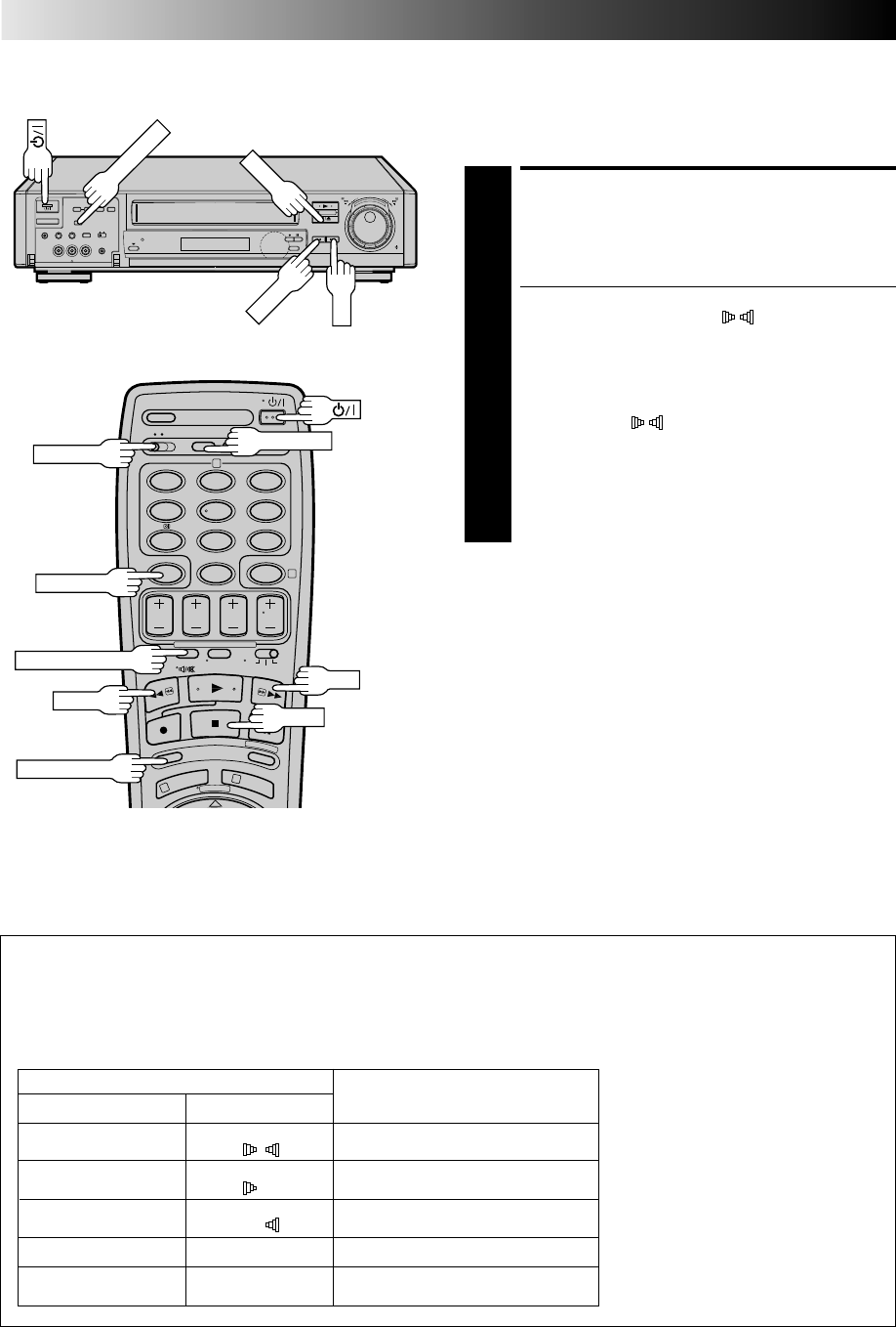
Your video recorder is capable of recording three soundtracks (HI-FI L, HI-FI R and NORM) and will play back the one you select.
During Playback
Pressing AUDIO MONITOR on the remote control changes the soundtrack being played back as follows:
TRACK
Recorder's Front Panel On-Screen Display USE
L + R HI FI For Hi-Fi stereo tapes
LR
LHI FI For main audio of Bilingual tapes
L
RHI FI For sub audio of Bilingual tapes
R
NORM NORM For audio-dubbed tapes
L + R + NORM HI FI For audio-dubbed tapes
NORM
NOTES:
●
"L + R" should normally be selected. In
this mode, Hi-Fi stereo tapes are played
back in stereo, and the normal audio
track is played back automatically for
tapes with only normal audio.
●
For instructions on recording stereo
and bilingual programmes, refer to
page 25.
●
"O.S.D." must be set to "ON" or the
on-screen displays will not appear
(
Z
pg. 27).
This feature expands sound field when you play back any stereo
source or view a stereo programme while recording it.
*SpatializerW has no effect on recording quality.
ACTIVATE SPATIALIZERW
1
Press SPATIALIZER; the current setting will be displayed
on the screen for about 5 seconds. Pressing
SPATIALIZER while the screen shows the display
changes the setting.
●To view a stereo programme such as movies or
music, select "SPATIALIZER " to create more
spacious sound.
●To view a monaural programme, select
"SPATIALIZER[ST" which simulates a stereo effect.
●Select "SPATIALIZER OFF" to turn off SpatializerW if
the sound becomes unnatural with either
"SPATIALIZER " or "SPATIALIZER[ST" selected.
●If your TV is equipped with 3D-PHONIC and if you
use both SpatializerW and 3D-PHONIC at the same
time, the sound may become unnatural; set either
function to "OFF".
●The setting will remain effective even though you
turn on/off the recorder.
NOTES:
●
Spatializer
W
is effective only with a stereo TV.
●
The setting cannot be changed during search, still, frame-by-
frame playback or slow motion mode.
●
When this recorder is used as the player for editing, the
recorded audio will correspond to the Spatializer
W
setting.
8
••
•
•
••
••
••
•
••
•
•
••
••
••
•
12
45
3
6
8
0
79
2
4
1
3
AUDIO MONITOR
C. MEMORY
A/B CODE
FF
REW STOP
C.RESET
FF
REW
SPATIALIZER
STOP
SCENE FINDER
EN 19
ACTIVATE SCENE FINDER
1
Press SCENE FINDER. The recorder starts forward
search for 5 seconds and then fast-forwards 10 minutes
on the counter. This cycle is repeated until the end of
the tape is reached.
●To start Scene Finder in the reverse direction, press
SCENE FINDER and then press the REW button
within 2 seconds. This cycle is repeated until the
beginning of the tape.
●During Scene Finder, the following indications appear
on the display panel:
STOP SCENE FINDER
2
Press STOP.
NOTES:
●
During Scene Finder search, you can also hear the tape
sound. During fast forward or rewind, you hear the current TV
sound instead.
●
During Scene Finder, the sound can be heard regardless of
"TIME SCAN AUDIO" setting.
Z
pg. 22.
●
Scene Finder does not function during Index Search.
This function helps you check contents of unlabeled recorded
tapes at the touch of a single button.
NOTE:
Scene Finder cannot be used when the recorder is in the Record
mode.
Scene Finder
10 minutes
on counter
FF REW FF REW FF REW
Search Search Search
5 seconds10 minutes
on counter
5 seconds 5 seconds
Remote A/B Code Switching
The remote control is capable of controlling two JVC video
recorders independently; one set to respond to the remote
control’s A code control signals and another set to respond to B
code control signals. The remote control is preset to send A
code signals because your video recorder is initially set to
respond to A code signals. You can easily modify your video
recorder to respond to B code signals.
REMOVE POWER SUPPLY
1
Unplug the mains power cord from the mains outlet.
SET A/B CODE SWITCH
2
Set to B.
RE-SUPPLY POWER
3
Plug the mains power cord back into the mains outlet.
TURN THE RECORDER ON
4
Press on the remote control. The recorder will now
only respond to B code signals.
NOTE:
Some TV sets may malfunction in response to the B mode. If
this happens, switch back to the A mode.
Counter Memory
Returns to the counter reading of “0:00:00” to conveniently find
a specific place on the tape automatically.
SET COUNTER MEMORY
1
Press C. RESET during playback at a point you wish to
locate later. The counter reads “0:00:00”. Then press
C.MEMORY, and “M” appears in front of the counter
digits.
ACTIVATE COUNTER
MEMORY
2
When you wish to return to the designated point, press
STOP and then REW or FF.
●The tape rewinds or fast-forwards and stops at about
0:00:00 automatically.
●To cancel Counter Memory, press C.MEMORY again.
Next Function Memory
You can set your recorder's power to go off automatically after
the tape is fully rewound. Before starting, make sure the
recorder is in the Stop mode.
For Automatic Power Off After Tape Rewind . . .
. . . press REW, then press within 2 seconds.
NOTE:
If you want the power to be turned off automatically when the
counter reads “0:00:00” (instead of at the beginning of the
tape), press C.MEMORY so that the “M” mark appears before
pressing REW.
20 EN
PLAYBACK (cont.)
TimeScan Your recorder is equipped with the TimeScan function. TimeScan
allows noise free pictures to be displayed on your TV screen in
the forward and reverse search modes. Audio will be played back
at normal speed during any of the TimeScan modes (Z pg. 21).
TimeScan allows you to view a program in search mode while
listening to the audio.
NOTES:
●
"TIME SCAN AUDIO" must be set to "ON", or the sound will
not be heard in TimeScan mode. (
Z
pg. 21)
●
The audio will not synchronize with the video in TimeScan
modes.
●
In Pause mode 3 seconds (approx.) of audio will be played
back repeatedly. (
Z
pg. 15)
●
In TimeScan search modes some of the audio information will
not be played so that the audio can keep up with the video.
12345
Audio signal during TimeScan
Sound of 1, 3 and 5 is heard.
Sound of 2 and 4 is not heard.
Output audio signal is normal (monaural) sound.
Playback tape
ACTIVATE VARIABLE-SPEED
SEARCH
1
During playback or still, turn the recorder's TIME SCAN
SHUTTLE ring. It remains at that position even after you
release it. Each time it passes a click position, the
playback speed changes.
(Refer to the chart on pg 21 for playback speeds).
OR
During playback, press PUSH JOG or .
●The more times you press, the faster the playback
picture moves.
●To decrease speed, press the button for the opposite
direction.
(Refer to the chart on pg 21 for playback speeds).
To resume normal playback, press PLAY.
Variable-Speed Search/
Reverse Play
%
%
8
••
•
•
••
••
••
•
••
•
•
••
••
••
•
12
45
3
6
8
0
79
2
4
1
3
PLAY
TIME SCAN INDICATOR
PUSH JOG
PLAY
TIME SCAN SHUTTLE
EN 21
Names of
special-effects
playback
Reverse Forward
Search Play Slow-Motion *Still Slow-Motion Play Search
-9x -7x -5x -3x -1x -1/6x -1/18x 0 1/18x 1/6x 1x 2x 3x 5x 7x 9x
-7x -3x -1/6x -1/18x 0 1/18x 1/6x 1x 2x 5x 9x
Audio is output. Audio is not Audio is Audio is not Audio is output.
output. output. output.
TimeScan
Speed LP
Speed SP
Audio output
* Still mode cannot be engaged using the remote control's PUSH JOG button. In the Still mode, the TIME
SCAN indicator does not light even though you can hear TimeScan audio.
●The recorder's TIME SCAN indicator lights during TimeScan.
●The speed is shown during TimeScan in the upper right corner of the TV screen for approx. 5 seconds. (The display may be
distorted.)
●To resume normal playback, press PLAY.
●When using the recorder's TIME SCAN SHUTTLE ring, the playback speed may not change depending on how far it is turned.
●Picture and audio may become distorted when the recording speed changes. When this happens, resume normal playback
once, and then try using TimeScan again.
●The picture may be noisy or there may be a loss of colour when you change the playback speed. (More noise will appear with
LP recordings.)
●Noise may appear or the upper part of the picture may be distorted during still, frame-by-frame playback, 2x search of LP
recordings, or depending on the tape being used.
●Picture may appear distorted in comparison to normal playback.
●In TimeScan mode there will be a time lag between the video and the audio and noise may appear in the audio signal.
●TimeScan sound quality will differ in comparison to normal playback.
●When the playback direction is reversed, it takes approximately 6 seconds until sound is heard.
●Picture will be monochrome with an LP-recorded MESECAM tape during TimeScan.
If you don't want to hear TimeScan audio, set "TIME SCAN AUDIO" to "OFF" (
Z
pg. 22).
22 EN
TimeScan Audio
The audio output can be set ON/OFF during TimeScan. Select
ON/OFF as required.
* The default setting is "ON".
ACCESS MAIN MENU
SCREEN
1
Press MENU twice.
ACCESS MODE SET
SCREEN
2
Move the highlight bar
(pointer) to "MODE SET"
by pressing PUSH JOG
%fi, then press OK.
SELECT MODE
3
Move the highlight
(pointer) to "TIME SCAN
AUDIO" by pressing PUSH
JOG %fi, then press PUSH
JOG to select "ON" or
"OFF".
RETURN TO NORMAL
SCREEN
4
Press MENU.
MAIN MENU
MODE SET
AUTO CH SET
MANUAL CH SET
GUIDE PROG SET
CLOCK SET
JLIP ID NO. SET
R.A. EDIT
[5∞] =
[MENU] : EXIT
5
12
45
3
6
8
0
79
2
4
1
3
PUSH JOG
OK
MENU
%
PLAYBACK (cont.)
MODE SET
AUTO TIMER : OFF
O. S. D. : ON
S-VHS : AUTO
EDIT : OFF
AV2 SELECT : AV2
TIME SCAN : ON
AUDIO
[5∞] = [ ] : ON/OFF
[MENU] : EXIT
EN 23
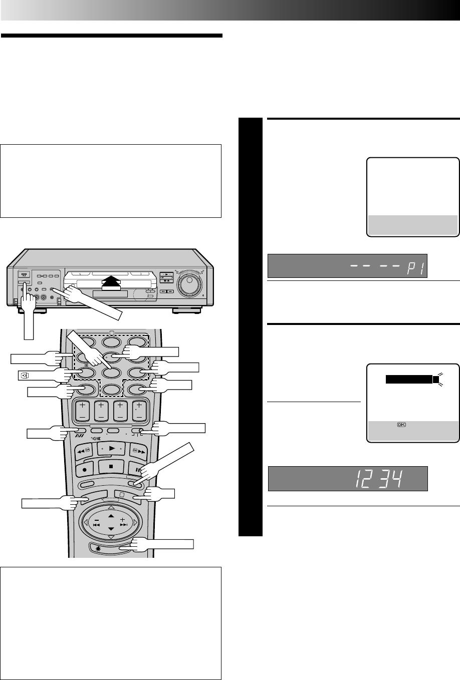
TV signals being received by the recorder’s built-in tuner can be
recorded onto a video tape. You can “capture” a TV programme
using your video recorder.
RECORDING
Basic
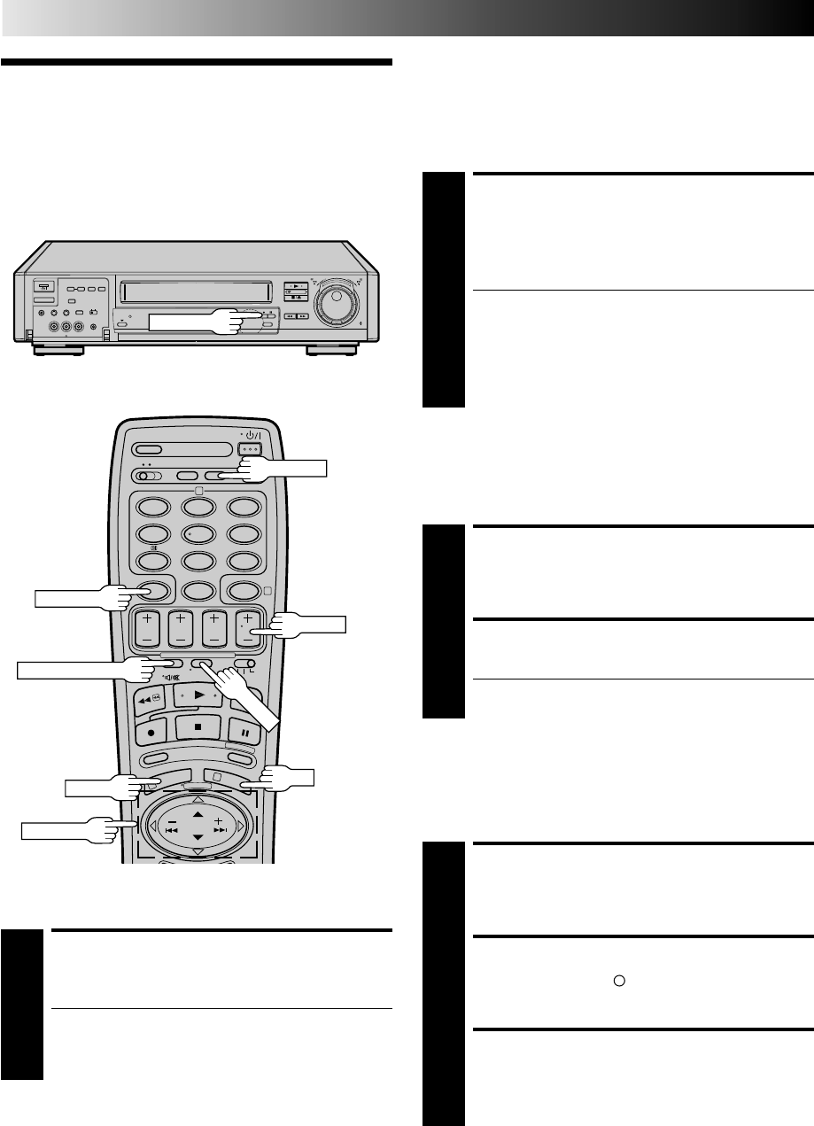
Recording LOAD A CASSETTE
1
Insert a cassette with the record safety tab intact.
●The counter is reset to 0:00:00 and the recorder
power comes on automatically.
CHOOSE A PROGRAMME
2
Press TV PROG +/– or the NUMBER keys to select the
channel you wish to record.
●The TV PROG dial can also be used to select a channel.
SET TAPE SPEED
3
Press SP/LP ( ). Check the SP/LP indicator on the
recorder display panel to confirm the selected tape
speed.
START RECORDING
4
Press and hold RECORD and PLAY on the remote
control, or press RECORD on the recorder.
PAUSE/RESUME
RECORDING
5
Press PAUSE. Press PLAY to resume recording.
STOP RECORDING
6
Press STOP on the remote control or STOP/EJECT on
the recorder. Then press STOP/EJECT to remove the
cassette.
●Turn on the TV and select the VIDEO channel (or AV mode).
●Set the PAL/MESECAM switch to the appropriate position.
Z pg. 16
12
45
3
6
8
0
79
2
4
1
3
8
••
•
•
••
••
••
•
••
•
•
••
••
••
•
PAUSE
NUMBER
STOP
PLAY
SP/LP
RECORD
●To prevent accidental recording on a recorded cassette,
remove its safety tab. To record on it later, cover the hole
with adhesive tape.
Record safety tab
Accidental erasure prevention
STOP/EJECT
PLAY
SP/LP
RECORD
PAUSE
PAL/MESECAM
TV PROG
TV PROG
24 EN
RECORDING (cont.)
Recording
Features
Record One Programme
While Watching Another
If your recorder is connected to the TV via AV connection, . . .
. . . press TV/VCR. The recorder's VCR indicator and the TV
broadcast being recorded disappear.
8
••
•
•
••
••
••
•
••
•
•
••
••
••
•
12
45
3
6
8
0
79
2
4
1
3
DISPLAY
C.RESET
TV/VCR
Tape Remaining Time
DISPLAY REMAINING TIME
1
Press DISPLAY until the time remaining on the tape
appears.
●By pressing the DISPLAY button, you can change the
display to show the counter reading, channel
position*, clock time or tape remaining time.
* channel position is not displayed during playback.
NOTE:
Depending on the type of tape used, there may be times when
the tape remaining time reading may not appear right away, or
is not correct. "- - : - -" may sometimes appear, or the display
may blink on occasion.
SELECT CHANNEL TO
WATCH
1
Once recording is in progress, all you need to do is to
set the channel controls on the TV for the station you
wish to view.
●The programme selected with the TV’s channel
controls appears on the TV screen while the one
selected with the recorder's TV PROG buttons is
recorded on the tape.
●If a decoder is connected to the recorder (Z pg. 45),
you can select a scrambled channel as well with the
TV channel controls.
Instant Timer Recording (ITR)
This easy method lets you record for from 30 minutes to 6 hours
(selectable in 30-min. increments), and shuts the recorder off
after recording is finished.
START RECORDING
1
Press RECORD on the recorder.
ENGAGE ITR MODE
2
Press RECORD again. " " blinks and 0:30 appears on
the front display panel.
SET RECORDING DURATION
3
If you want to record for more than 30 minutes, press
RECORD to extend the time. Each press extends
recording time by 30 minutes.
NOTE:
You can only perform ITR using the RECORD button on the
recorder's front panel.
Elapsed Recording Time
Indication
You can check the exact time of a recording.
SET COUNTER DISPLAY
1
Press DISPLAY until a counter reading appears on the
dispay panel.
RESET COUNTER
2
Press C. RESET before starting recording or playback.
●The counter is reset to “0:00:00” and shows the exact
elapsed time as the tape runs.
RECORD
AUDIO MONITOR
PUSH JOG
MENU OK
TV PROG
EN 25
Receiving Stereo And Bilin-
gual Programmes
Your recorder is equipped with a Sound-Multiplex decoder (A2) and,
if you own the HR-S9400EH, a Digital stereo sound decoder
(NICAM) as well, making reception of stereo and bilingual broad-
casts possible.
When the channel is changed, the type of broadcast being
received will be displayed on the TV screen for a few seconds.
To Record Stereo And Bilin-
gual Programmes (A2)
●Stereo programmes are automatically recorded in stereo on
the Hi-Fi audio track (with the normal audio track recording
mixed L and R channel sound).
●Bilingual programmes are automatically recorded in bilingual
on the Hi-Fi audio track. The main soundtrack will be recorded
on the normal audio track.
NOTES:
●
If the quality of stereo sound being received is poor, the
broadcast will be received in monaural with better quality.
●
Before playing back a programme recorded in stereo, or a
bilingual programme, refer to "Soundtrack Selection" (
Z
pg. 18).
Type of Broadcast On-screen Display
Being Received
A2 Stereo ST
A2 Bilingual BIL
Regular Monaural (none)
*NICAM Stereo ST NICAM
*NICAM Bilingual BIL NICAM
*NICAM Monaural NICAM
*Available with HR-S9400EH only.
To Record NICAM Stereo
And Bilingual Programmes
(HR-S9400EH only)
●The NICAM audio programme will be recorded on the Hi-Fi
audio track, and the Standard audio programme on the
normal audio track.
S-VHS (Super VHS) and VHS
Your recorder can record in either S-VHS or VHS.
To record in S-VHS;
●insert a cassette marked "S-VHS", the "S" (S-VHS) indicator
will light on the display panel.
●then, perform the steps 1 – 4 below to set the "S-VHS" to "AUTO".
The S-VHS recording mode will be selected.
To record in VHS;
●insert a cassette marked "VHS".
The VHS recording mode will be automatically selected
regardless of the S-VHS mode setting.
To record in VHS on an S-VHS cassette;
●insert the cassette marked "S-VHS", the "S" (S-VHS) indicator
will light on the display panel.
●then, perform the steps 1 – 4 below to set the "S-VHS" to
"OFF"; the "S" (S-VHS) indicator will go out.
The VHS recording mode will be selected.
ACCESS MAIN MENU
SCREEN
1
Press MENU twice.
ACCESS MODE SET
SCREEN
2
Move the highlight bar
(pointer) to "MODE SET"
by pressing PUSH JOG
%fi, then press OK.
SELECT MODE
3
Move the highlight
(pointer) to "S-VHS" by
pressing PUSH JOG %fi,
then press PUSH JOG to
select "AUTO" or "OFF".
RETURN TO NORMAL
SCREEN
4
Press MENU.
MAIN MENU
MODE SET
AUTO CH SET
MANUAL CH SET
GUIDE PROG SET
CLOCK SET
JLIP ID NO. SET
R.A. EDIT
[5∞] =
[MENU] : EXIT
5
%
MODE SET
AUTO TIMER :OFF
O. S. D. : ON
S-VHS :AUTO
EDIT :OFF
AV2 SELECT :AV2
TIME SCAN :ON
AUDIO
[5∞] = [ ] : AUTO/OFF
[MENU] : EXIT
●To listen to a stereo programme, press AUDIO MONITOR
until "L" and "R" appear on the front display panel.
●To listen to a bilingual programme, press AUDIO MONITOR
until either "L" or "R" appears on the front display panel (as
required).
●To listen to the Standard (regular monaural) audio while
receiving a NICAM broadcast, press AUDIO MONITOR until
"NORM" appears on the front display panel. (HR-S9400EH
only)
NOTE:
"O.S.D." must be set to "ON" or the on-screen displays will not
appear (
Z
pg. 27).
26 EN
RECORDING (cont.)
ADJUST AUDIO RECORDING
LEVEL
1
Turn Hi-Fi REC LEVEL in either direction.
●When the level indicator lights up to or near 0dB
with the loudest signal being applied, the recording
level is optimum.
NOTES:
●
Make sure that the "HI-FI L+R" position is selected with the
AUDIO MONITOR button.
Z
p. 18
●
Noise will increase if the recording level is too low, while
distortion will increase if the level is too high.
Hi-Fi Audio Recording LEVEL
Control
In most cases, setting the Hi-Fi audio recording level control to
the center position will provide satisfactory results. If necessary,
you can adjust the Hi-Fi audio recording level more precisely
by reffering to the audio level indicator on the front panel.
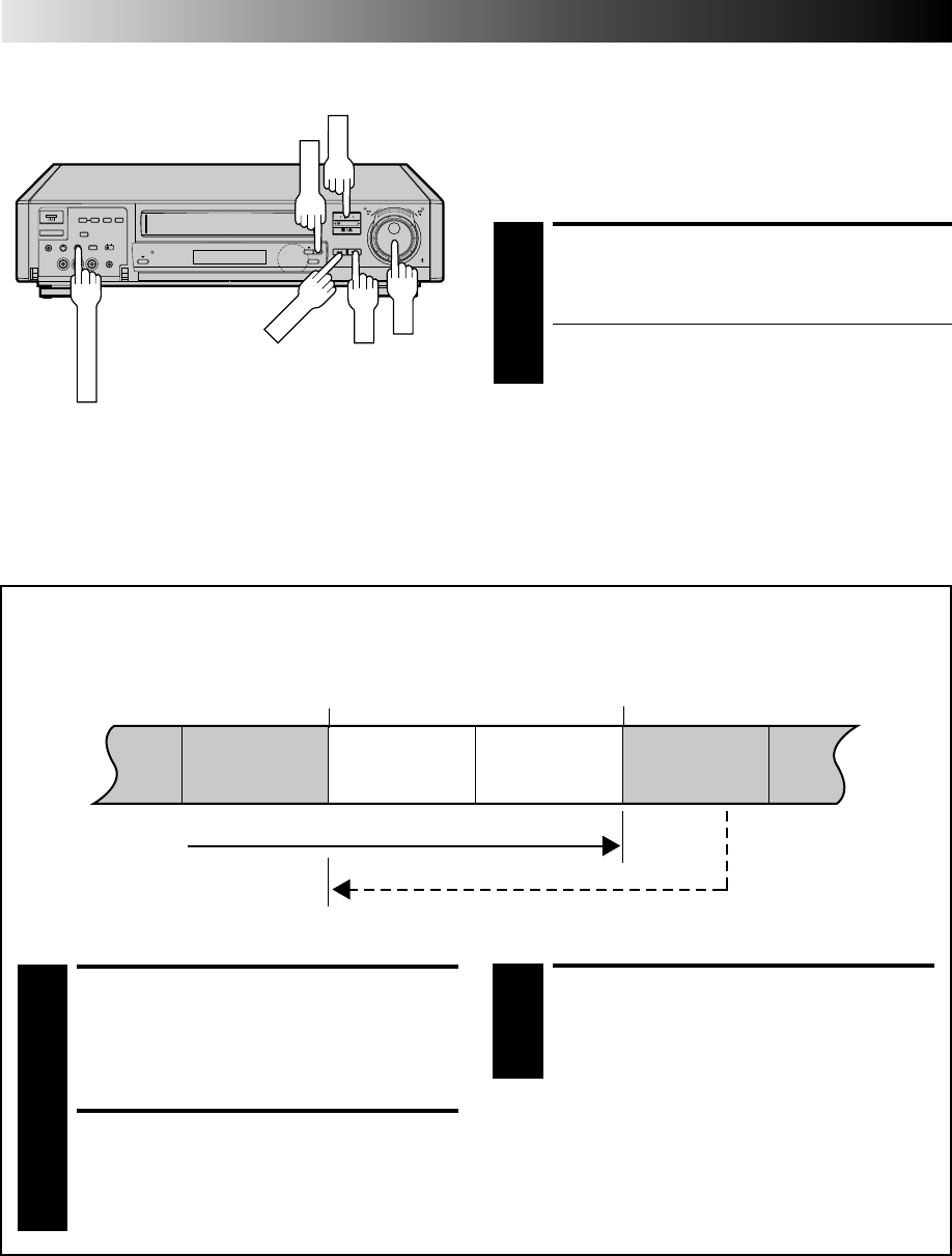
Retake
You can cut out unnecessary parts of a TV programme while you're recording it.
End of programme
Programme
Beginning of programme
Programme
Recorded part
RESUME RECORDING
3
Press PLAY when you wish to resume recording.
ENGAGE RECORD-PAUSE
MODE
1
Press PAUSE during recording.
LOCATE START POINT
2
Turn the JOG dial (or hold down REW or FF) and
release it when you reach the point where you want
to resume recording.
* Your recorder returns to the Record-Pause mode.
Go back to end of programme to cut out
unnecessary part
Unnecessary
part Unnecessary
part
8
••
•
•
••
••
••
•
••
•
•
••
••
••
•
Hi-Fi REC LEVEL
FF
REW
PAUSE
PLAY
JOG

EN 27
On-Screen
Displays
You can choose whether or not to have various operational
indicators appear on screen, by setting this function ON or OFF.
Messages appear in the selected language (Z pg. 8 or 9).
Turn on the TV and select the VIDEO channel (or AV mode).
TURN ON THE RECORDER
1
Press .
ACCESS MAIN MENU
SCREEN
2
Press MENU twice.
ACCESS MODE SET
SCREEN
3
Move the highlight bar (pointer) to "MODE SET" by
pressing PUSH JOG %fi, then press OK.
ENABLE/DISABLE
ON-SCREEN DISPLAY
4
The default setting is
“ON”, so if you want on-
screen displays, leave the
setting as it is and go to
step 5. If you don’t want
the displays to appear,
press PUSH JOG %fi to
move the highlight bar
(pointer) to "O.S.D." and
press PUSH JOG to set
“O.S.D.” to “OFF”.
RETURN TO NORMAL
5
Press MENU.
NOTES:
●
When you use this recorder as the player for editing, be sure
to set "O.S.D." to "OFF." before starting.
●
During playback, the operation mode indicators may be
disturbed depending on the type of tape being used.
1– Operation mode indicators
2– Channel position number and station name/Aux. indicator
(AUX1, AUX2, (S) or F-AUX)
3– Cassette loaded mark
4– Tape speed SP/LP
5– Clock display
6– Current day/month/year
7– Type of Broadcast (Z pg. 25)
8– Tape direction
9– Tape position indicator (Z pg. 17)
10– Counter display (including Counter Memory indicator)
11– Audio mode display (Z pg. 18)
12– Tape remaining time indicator (Z pg. 24)
13– Timer warning display (Z pg. 33)
14– SpatializerW indicator (Z pg. 18)
q6
PR. 12 ABCD ]SP
21 : 00
24. 12. 97 – WARNING–
TIMER RECORDING
TO START SOON
SPATIALIZER [CANCEL]
ST
HI FI M –1 : 23 : 45
NORM REMAIN 1 : 00
0
+++
+
13
2
5
6
7
9
11
14
10
12
8
4
13
12
45
3
6
8
0
79
2
4
1
3
PUSH JOG
OK
MENU
%
5
MODE SET
AUTO TIMER : OFF
O. S. D. : ON
S-VHS : AUTO
EDIT : OFF
AV2 SELECT : AV2
TIME SCAN : ON
AUDIO
[5∞] = [ ] : ON/OFF
[MENU] : EXIT
The superimposed indication on the TV screen tells you what the recorder is doing.
28 EN
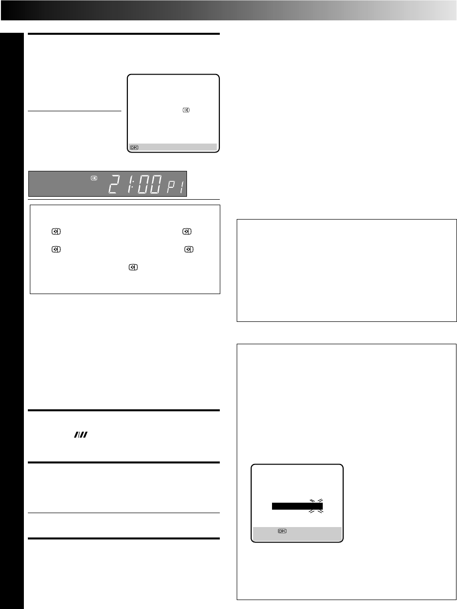
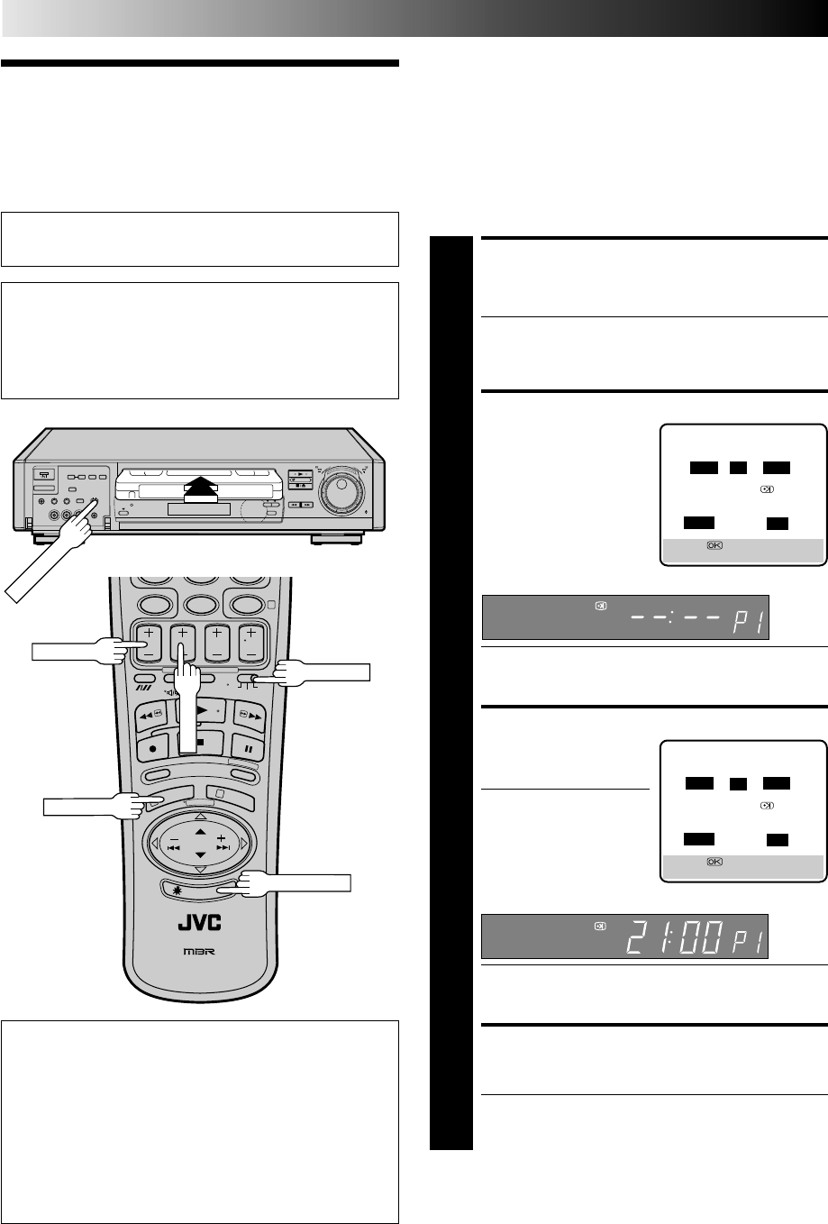
TIMER RECORDING
SHOWVIEW
Timer
Recording
During SHOWVIEW and regular timer programming, the Illumi-
Guide feature tells you which button on the remote control
must be pressed next by lighting it up. To use this feature, with
the TV/SAT/VCR switch set to "VCR", press ILLUMI GUIDE
before performing step 1. (PROG, REW, PLAY, FF light up at this
time.)
If you aren't going to use the Illumi-Guide feature, go directly to
step 1.
ACCESS TIMER PROGRAM-
MING SCREEN
1
Press PROG.
The front display panel looks like this:
●If you are using the Illumi-Guide feature, the following
buttons will light up: NUMBER keys (0–9), START +/–,
STOP +/–, DATE +/–, TV PROG +/–, MENU and
CANCEL.
ENTER SHOWVIEW
NUMBER
2
Press the NUMBER keys to
enter the SHOWVIEW
number of a programme
you wish to record.
●If you make a mistake,
press CANCEL to
backspace and then
input the correct number.
The SHOWVIEW number
you enter appears on the front display panel:
The display panel can only show 4 digits at a time.
●If you are using the Illumi-Guide feature, OK blinks
when the following buttons are lit: NUMBER keys (0–
9), CANCEL and MENU.
TIMER PROGRAMMING
[0 – 9] : SHOWVIEW
[+/–] : EXPRESS PROGRAMMING
[MENU] : MAIN MENU
SHOWVIEW
12345678
[0 – 9] =
[CANCEL] : DELETE
[MENU] : EXIT
Before performing SHOWVIEW timer recording:
●Be sure to read "SHOWVIEW Setup" (Z pg. 12).
●Insert a cassette with the safety tab in place. The recorder
will come on automatically.
●Turn on the TV and select the VIDEO channel (or AV mode).
●Set the PAL/MESECAM switch to the appropriate position.
Z pg. 16
* For Customers in Australia and New Zealand:
With this recorder, the G-Code system is identified as "SHOWVIEW".
8
••
•
•
••
••
••
•
••
•
•
••
••
••
•
12
45
3
6
8
0
79
2
4
1
3
OK
CANCEL
:PDC/VPS
ADD TIME
WEEKLY
TIMER
ILLUMI GUIDE
DAILY
NUMBER
SP/LP
TIMER
When Using The Illumi-Guide Feature
●Buttons light or blink on the remote control for
approximately 10 seconds. If the button or buttons extinguish
during timer programming, press ILLUMI GUIDE and the
button or buttons previously lit or blinking come back on. If
the button or buttons do not re-light or start blinking again,
press MENU and re-perform the timer programming
procedure from the beginning.
●If for some reason the remote control's signal is not received
by the video recorder, press MENU and re-perform the timer
programming procedure from the beginning.
PAL/MESECAM
TV/SAT/VCR
PROG CHECK
PROG/MENU
EN 29
ACCESS SHOWVIEW
PROGRAM SCREEN
3
Press OK, and the
SHOWVIEW Program screen
appears (if you’re just
starting out, “P1” appears).
The display panel shows
the programme start time.
Pressing PROG CHECK
changes the display to the
programme stop time, then
the date and channel position.
IMPORTANT
Be sure to confirm the setting of PDC/VPS recording.
●If " ON" is displayed on the screen or " " is lit
on the display panel, PDC/VPS is set to ON.
●If " OFF" is displayed on the screen or " " is
not lit on the display panel, PDC/VPS is set to OFF.
To change the setting, press : PDC/VPS
(NUMBER key "7").
Z "PDC/VPS Recording" on page 33.
●Make sure the channel position number you wish to
record is displayed; if not, see "SHOWVIEW Setup" on
page 12 and set the Guide Program number for that
SHOWVIEW number correctly.
●If the number you entered is invalid, "ERROR"
appears on the screen and "Err" appears on the
display panel. Press CANCEL to backspace and input
a valid SHOWVIEW number.
●If "ERROR=GUIDE PROG" appears on the screen, see
"ATTENTION – Regarding Guide Program Number
Set" in the right column.
●If you are using the Illumi-Guide feature, OK blinks.
SET TAPE SPEED
4
Press SP/LP ( ) to set the tape speed.
RETURN TO NORMAL
SCREEN
5
Press OK.
●Repeat steps 1 – 5 for each additional programme.
ENGAGE RECORDER’S
TIMER MODE
6
Press TIMER. The recorder turns off automatically.
NOTE:
To Delay The Stop Time . . .
. . . press ADD TIME (NUMBER Key "5") after pressing OK in
step 3. Each time you press, the Stop time is delayed by 5
minutes (meaning that 5 minutes of recording time is added).
You can easily compensate for anticipated programme schedule
delays this way.
To Timer-Record Weekly Or Daily Serials . . .
. . . after pressing OK in step 3, press WEEKLY (NUMBER key
“9”) for weekly serials or DAILY (NUMBER key “8”) for daily
serials (Monday–Friday). Either "WEEKLY" or "DAILY" appears
on the screen. Pressing the button again makes the correspond-
ing indication disappear.
You can programme this recorder to timer-record as many as 8
programmes. If you try to programme the recorder to record a
ninth, "PROGRAM FULL" appears on screen and "FULL" appears
on the front display panel. To record the extra programme, you
must first cancel any unnecessary programmes (Z pg. 32).
– P1 –
SHOWVIEW 123456789
START STOP
21:00 =22:00
SP ON
DATE TV PROG
25.12 1
ARD
: OK
SP
Satellite Tuner Users
To timer-record a satellite broadcast using SHOWVIEW:
● Before you start step 1, be sure to set the recorder's input
mode to "AUX2" (Z pg. 35). Do NOT change the input
mode until the selected programme has been timer-
recorded.
● Before the selected programme begins, select the
appropriate channel on the satellite tuner, and then set
the tuner's timer. If your satellite tuner does not have a
timer, leave the unit's power on.
ATTENTION
Regarding Guide Program Number Set
"ERROR=GUIDE PROG" appears after performing step 3 on
the previous page if the Guide Program number for the
SHOWVIEW number you entered has not been set.
●If the recorder is in the stop or rewind or fast-forward
mode, the following screen will appear with "– –" under
"TV PROG" blinking.
•Press the NUMBER keys or PUSH JOG %fi to input the
channel position number you recorder receives that
station on, then press OK.
•Press MENU, then try again from step 1.
●If the recorder is in a mode other than the above mentioned
modes, press MENU first and input the correct Guide
Program number for that SHOWVIEW number (Z pg. 12,
"SHOWVIEW Setup"), then try again from step 1.
GUIDE PROG SET
GUIDE PROG TV PROG
2 – –
[5∞] =
[MENU] : EXIT
(Ex.) To timer-record a ZDF
programme with SHOWVIEW
* If your recorder receives
ZDF on the channel
position 2, press OK after
entering "2".
30 EN
TIMER RECORDING(cont.)
Regular Timer
Programming
Remember, the clock must be set before you can
programme the timer (Z pg. 55).
If you don’t know the SHOWVIEW number for the programme
you wish to record, use the following procedure to set your
recorder to timer-record the programme. Or you can use the
Illumi-Guide feature, where the remote control tells you which
button to press next by lighting it up. To use the Illumi-Guide
feature, with the TV/SAT/VCR switch set to "VCR", press
ILLUMI GUIDE before performing step 1. (PROG, REW, PLAY,
FF light up at this time.)
If you aren't going to use the Illumi-Guide feature, go directly to
step 1.
Before performing the following steps:
●Insert a cassette with the safety tab in place. The recorder
will come on automatically.
●Turn on the TV and select the VIDEO channel (or AV mode).
●Set the PAL/MESECAM switch to the appropriate position.
Z pg. 16
ACCESS TIMER
PROGRAMMING SCREEN
1
Press PROG.
●If you are using the Illumi-Guide feature, the following
buttons will light up: NUMBER keys (0–9), START +/–,
STOP +/–, DATE +/–, TV PROG +/–, MENU and
CANCEL.
ACCESS PROGRAMME SCREEN
2
Press START +/–. (If you’re
just starting out, “P1”
appears.)
The front display panel looks like this:
●If you are using the Illumi-Guide feature, the following
buttons will light up: START +/–, STOP +/–, DATE +/–,
TV PROG +/– and MENU.
ENTER PROGRAMME START TIME
3
Press START +/– to enter
the time you want
recording to start.
●Press and hold START
+/– to move in 30-
minute increments, or
press and release
repeatedly to move 1
minute at a time.
The front display panel looks like this:
●If you are using the Illumi-Guide feature, the following
buttons remain lit: START +/–, STOP +/–, DATE +/–,
TV PROG +/– and MENU.
ENTER PROGRAMME STOP TIME
4
Press STOP +/– to enter the time you want recording to
stop.
●If you are using the Illumi-Guide feature, the following
buttons remain lit: START +/–, STOP +/–, DATE +/–,
TV PROG +/– and MENU.
– P1 –
START STOP
–:– – =–:– –
SP ON
DATE TV PROG
25.12 – –
[+/–] =
[MENU] : EXIT
SP
– P1 –
START STOP
21:00 =–:– –
SP ON
DATE TV PROG
25.12 – –
[+/–] =
[MENU] : EXIT
SP
When Using The Illumi-Guide Feature
●Buttons light or blink on the remote control for
approximately 10 seconds. If the button or buttons extinguish
during timer programming, press ILLUMI GUIDE and the
button or buttons previously lit or blinking come back on. If
the button or buttons do not re-light or start blinking again,
press MENU and re-perform the timer programming
procedure from the beginning.
●If for some reason the remote control's signal is not received
by the video recorder, press MENU and re-perform the timer
programming procedure from the beginning.
8
0
79
4
1
3
START+/–
STOP+/–
8
••
•
•
••
••
••
•
••
•
•
••
••
••
•
ILLUMI GUIDE
PAL/MESECAM
TV/SAT/VCR
PROG/MENU
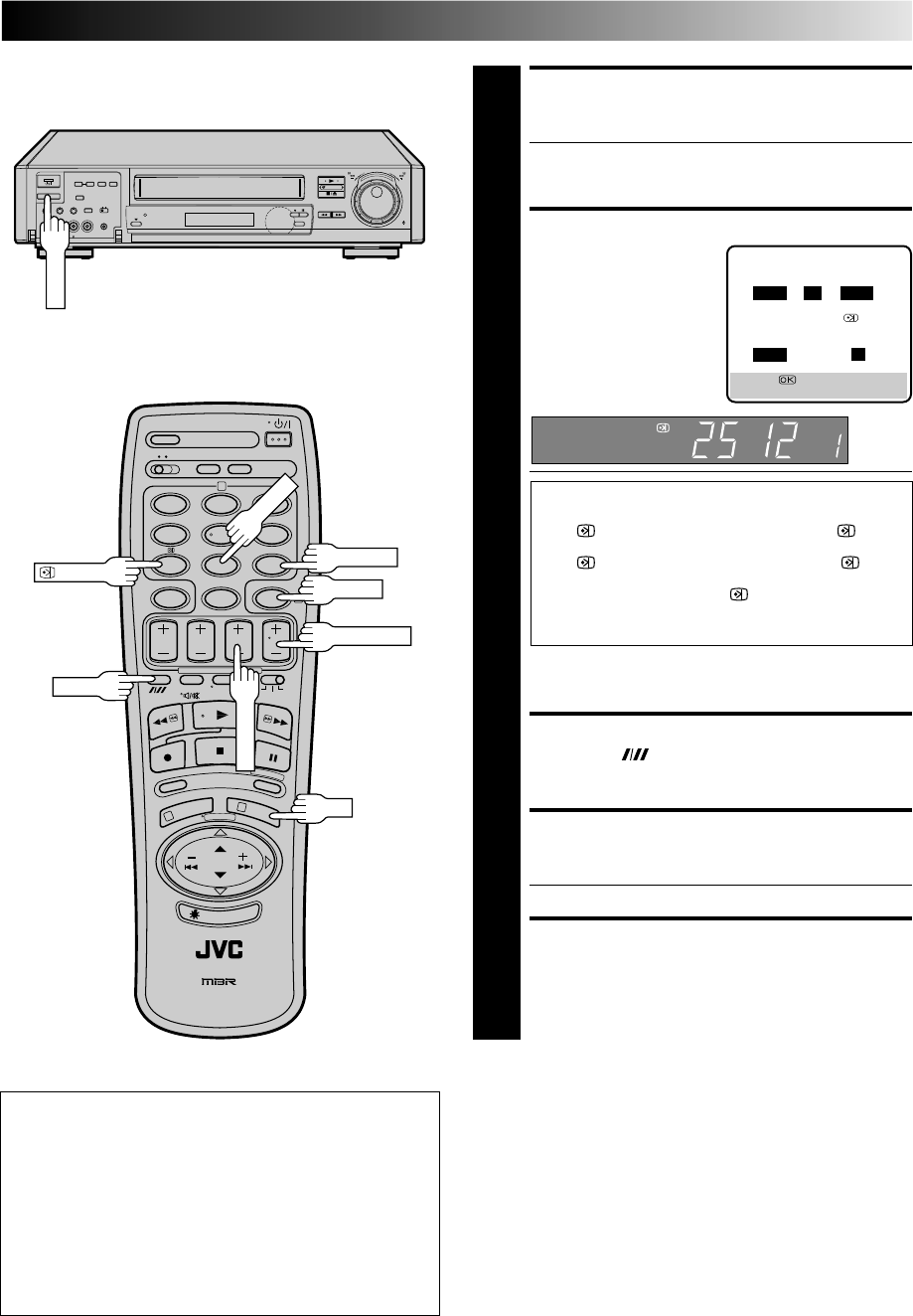
EN 31
ENTER PROGRAMME DATE
5
Press DATE +/–. (The current date appears on screen.
The date you enter appears in its place.)
●If you are using the Illumi-Guide feature, the following
buttons remain lit: START +/–, STOP +/–, DATE +/–,
TV PROG +/– and MENU.
ENTER CHANNEL POSITION
6
Press TV PROG +/–.
IMPORTANT
Be sure to confirm the setting of PDC/VPS recording.
●If " ON" is displayed on the screen or " " is lit
on the display panel, PDC/VPS is set to ON.
●If " OFF" is displayed on the screen or " " is
not lit on the display panel, PDC/VPS is set to OFF.
To change the setting, press : PDC/VPS
(NUMBER key "7").
Z "PDC/VPS Recording" on page 33.
●If you are using the Illumi-Guide feature, OK blinks
when the following buttons are lit: START +/–, STOP
+/–, DATE +/–, TV PROG +/– and MENU.
SET TAPE SPEED
7
Press SP/LP ( ) to set the tape speed.
RETURN TO NORMAL SCREEN
8
After confirming all information is correct, press OK
and the normal screen appears.
●Repeat steps 1–8 for each additional programme.
ENGAGE RECORDER’S TIMER
MODE
9
Press TIMER. The recorder turns off automatically.
To Timer-Record Weekly Or Daily Serials . . .
. . . anytime during steps 2 through 8, press WEEKLY (NUMBER
key “9”) for weekly serials or DAILY (NUMBER key “8”) for
daily serials (Monday–Friday). Either "WEEKLY" or "DAILY"
appears on the screen. Pressing the button again makes the
corresponding indication disappear.
8
••
•
•
••
••
••
•
••
•
•
••
••
••
•
12
45
3
6
8
0
79
2
4
1
3
DAILY
OK
WEEKLY
TIMER
:PDC/VPS
– P1 –
START STOP
21:00 =22:00
SP ON
DATE TV PROG
25.12 1
ARD 1
[+/–] =
[MENU] : EXIT
SP
SP/LP
DATE+/–
NOTE:
You can programme this recorder to timer-record as many as 8
programmes. If you try to programme the recorder to record a
ninth, "PROGRAM FULL" appears on screen and "FULL" appears
on the front display panel. To record the extra programme, you
must first cancel any unnecessary programmes (
Z
pg. 32).
Satellite Tuner Users
To timer-record a satellite broadcast using Regular Timer
Programming:
● Before you start step 1, be sure to set the recorder's input
mode to "AUX2" (Z pg. 35). Do NOT change the input
mode until the selected programme has been timer-
recorded. In step 6, you have to select "AUX2" as well.
● Before the selected programme begins, select the
appropriate channel on the satellite tuner, and then set
the tuner's timer. If your satellite tuner does not have a
timer, leave the unit's power on.
TIMER
TV PROG+/–
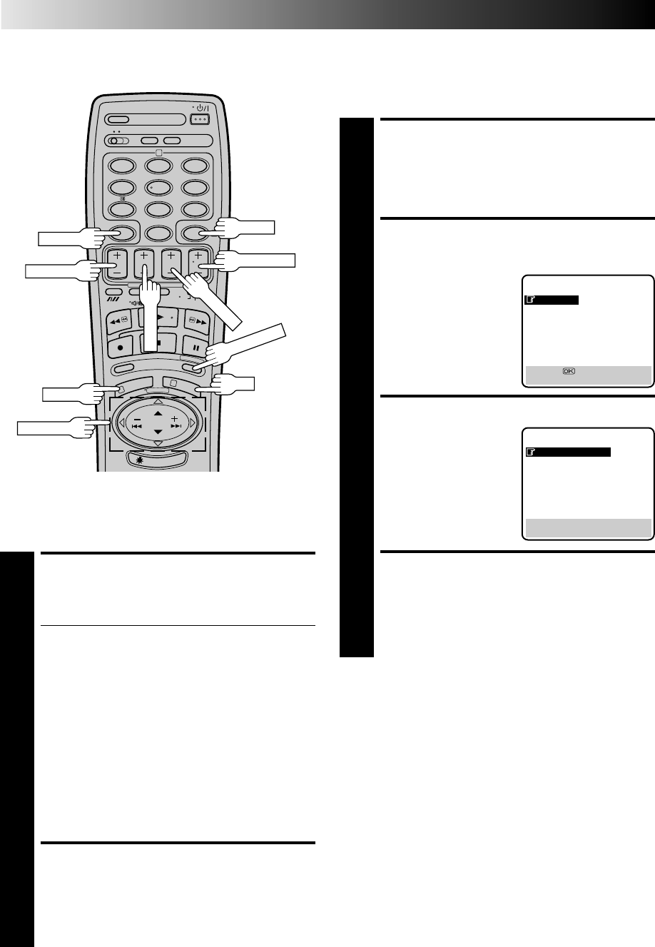
32 EN
12
45
3
6
8
0
79
2
4
1
3
OK
CANCEL
START+/–
DATE+/–
STOP+/–
Auto Timer
When the Auto Timer is set to ON the timer is automatically
engaged when the recorder power is turned off and automati-
cally disengaged when the recorder is powered back on.
ACCESS MAIN MENU
SCREEN
1
Press MENU twice.
ACCESS MODE SET
SCREEN
2
Press PUSH JOG %fi to
move the highlight bar
(pointer) to "MODE SET",
then press OK.
SELECT MODE
3
Press PUSH JOG to select
either "ON" or "OFF".
RETURN TO NORMAL
SCREEN
4
Press MENU.
NOTE:
For safety, when Auto timer is set to "OFF", all other recorder
functions are disabled while the Timer mode is engaged. To
disengage the timer, press TIMER.
%
MENU
5
MODE SET
AUTO TIMER : OFF
O. S. D. : ON
S-VHS : AUTO
EDIT : OFF
AV2 SELECT : AV2
TIME SCAN : ON
AUDIO
[5∞] = [ ] : ON/OFF
[MENU] : EXIT
MAIN MENU
MODE SET
AUTO CH SET
MANUAL CH SET
GUIDE PROG SET
CLOCK SET
JLIP ID NO. SET
R.A. EDIT
[5∞] =
[MENU] : EXIT
TIMER RECORDING (cont.)
TIMER
PUSH JOG
Check And Cancel
Programmes
ACCESS PROGRAMME
DISPLAY AND/OR SCREEN
1
Press PROG CHECK.
●The display panel shows the programme start time.
Pressing OK changes the display to the programme
stop time, then the date and channel position.
●If the recorder is turned on and the TV is set to its
VIDEO channel or AV mode, you can check program
information on screen as well.
●Each time you press PROG CHECK, the next
programme's information appears.
If All Information Is Correct . . .
. . . programming is completed.
If You Wish To Revise Data . . .
. . . with the recorder's power turned on, go to step 2.
If You Wish To Cancel A Program . . .
. . . with the recorder's power turned on, press CANCEL.
All information you input is deleted.
REVISE PROGRAMME
INFORMATION
2
Input the appropriate data using the START +/–, STOP
+/–, DATE +/– and TV PROG +/– buttons on the
remote control.
PROG CHECK
TV PROG+/–
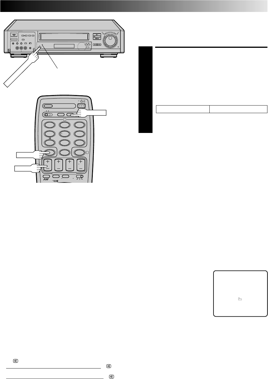
EN 33
Auto SP/LP Timer
If, when recording in SP mode, there is not enough tape to
record the entire programme, the recorder automatically
switches to LP mode to allow complete recording.
ENGAGE AUTO SP/LP
TIMER
1
Press AUTO SP/LP TIMER on the recorder front panel.
The AUTO SP/LP TIMER indicator lights up.
For Example . . .
Recording a programme of 210 minutes in length onto
a 180-minute tape
Make sure you press AUTO SP/LP TIMER before
performing timer programming.
NOTES:
●
The Auto SP/LP Timer feature is not available during ITR
(Instant Timer Recording), and the feature will not work
properly with any tapes longer than E-180 as well as some
tapes of shorter lenghs.
●
Even if, in step 1, you press AUTO SP/LP TIMER and the
indicator lights up, that doesn’t mean that the recorder will
automatically change from SP to LP mode during the course
of the recording. Watch the tape later to confirm.
●
If you have programmed the recorder to timer-record 2 or
more programs, the second programme and those thereafter
may not fit on the tape if you engage the Auto SP/LP Timer
mode. In this case, make sure the mode is not engaged, then
set the tape speed manually during timer programming.
●
There may be some noise at the point on the tape where the
recorder switches from SP to LP mode.
●
If you perform timer recording with both PDC/VPS and the
Auto SP/LP Timer activated, and the programme goes beyond
its originally scheduled length, there may be times when the
programme cannot be recorded in its entirety.
Approximately 150 minutes Approximately 60 minutes
Total 210 minutes
SP mode LP mode
Timer Warning
If you have programmed your
recorder to timer-record a
programme or a series of
programmes, a warning appears on
screen to tell you that the record-
ing is to start in 5 minutes.
NOTES:
●
The warning only appears if
you’re not in the Timer mode at
that time.
●
If this recorder is being used as the player for tape dubbing,
the warning screen is recorded on the tape in the other video
recorder.
The warning blinks for the entire 5 minutes leading up to the
start of timer recording. To clear the display, press CANCEL.
– WARNING–
TIMER RECORDING
TO START SOON
[CANCEL]
PDC/VPS Recording
Now available from some TV stations, PDC (Programme Delivery
Control) and VPS (Video Programme System) are service designed
to assure safe, accurate timer recording. With this system, special
code signals are transmitted together with the audio/video
signals. These code signals control your video recorder and have
precedence over advertised times you preset in the timer. This
means that your recorder will start and stop recording when the
preset TV programmes actually start and end — even if the
broadcast time of a preset TV programme is changed.
NOTES:
●
When you manually enter programmes (regular timer
programming), set the start time (PDC or VPS time) exactly as
advertised in the TV listing. A different time than advertised
will result in no recording.
●
PDC/VPS recording is not possible in areas where no TV
station transmits PDC or VPS signals.
●
PDC/VPS recording is also possible when a satellite tuner or a
cable system is connected to the AV2 IN/DECODER
connector on your recorder.
●
PDC/VPS recording is also possible via the AV1 IN/OUT
connector and the front panel connectors.
8
••
•
•
••
••
••
•
••
•
•
••
••
••
•
12
45
3
6
8
0
79
2
4
CANCEL
DISPLAY
START+
AUTO SP/LP TIMER
AUTO SP/LP TIMER indicator
How to check if the station being received transmits a
PDC/VPS signal
1Press DISPLAY until the channel position appears on the
display panel.
2Hold down START + for about 5 seconds.
●" " appears blinking on the display panel.
If a PDC/VPS signal is detected from the station
, " " will
stop blinking.
If no PDC/VPS signal is detected from the station
, " " will
blink at a slower rate.
3Press DISPLAY or START + again to return to normal display.

34 EN
Preparation
For Editing
●Turn on the TV and select the VIDEO channel (or AV mode).
●Set the PAL/MESECAM switch to the appropriate position.
Z pg. 16
Editing Mode Setting
You can minimize picture degradation while editing.
ACCESS MAIN MENU
SCREEN
1
Press MENU twice.
ACCESS MODE SET
SCREEN
2
Move the highlight bar
(pointer) to "MODE SET"
by pressing PUSH JOG
%fi, then press OK.
SELECT MODE
3
Move the highlight
(pointer) to "EDIT" by
pressing PUSH JOG %fi,
then press PUSH JOG to
select "ON".
RETURN TO NORMAL
SCREEN
4
Press MENU.
MAIN MENU
MODE SET
AUTO CH SET
MANUAL CH SET
GUIDE PROG SET
CLOCK SET
JLIP ID NO. SET
R.A. EDIT
[5∞] =
[MENU] : EXIT
5
%
MODE SET
AUTO TIMER : OFF
O. S. D. : ON
S-VHS : AUTO
EDIT : ON
AV2 SELECT : AV2
TIME SCAN : ON
AUDIO
[5∞] = [ ] : ON/OFF
[MENU] : EXIT
NOTE:
After you finish editing, be sure to set "EDIT" back to "OFF".
Advantages Of S-VHS
Video Recorders
8
••
•
•
••
••
••
•
••
•
•
••
••
••
•
12
45
3
6
8
0
79
2
4
1
3
PUSH JOG
MENU OK
EDITING
AV/S SELECT
PAL/MESECAM
NUMBER "0"
You can edit from VHS to S-VHS, S-VHS to VHS, or, from
S-VHS to S-VHS.
●From VHS to S-VHS (VIDEO-VIDEO connection): Record
VHS playback signals in the S-VHS mode. Although the
picture quality is inherently limited by that of the
original, the edited tape has better picture quality than
those made by VHS-to-VHS editing.
●From S-VHS to VHS (VIDEO-VIDEO connection):
Because the picture quality of the source material is very
high, the edited tape has better picture quality than those
made by VHS-to-VHS editing.
●From S-VHS to S-VHS (S-VIDEO connection): All signals
will be transferred without degradation.
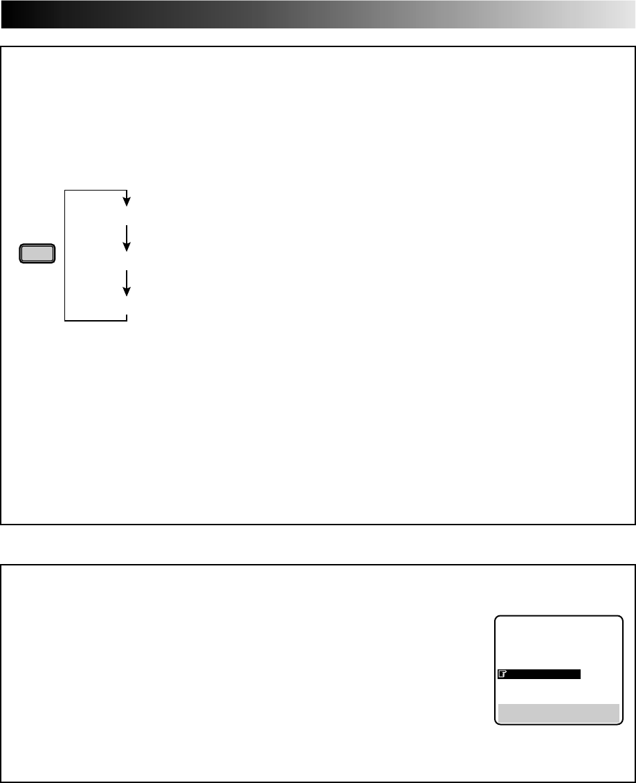
EN 35
To Select The External Input Mode
To record external audio and video signals;
1Press the remote control's NUMBER key "0".
2Press AV/S SELECT on the front of the recorder to select the appropriate external input mode.
●Pressing AV/S SELECT rotates the input mode as follows:
AV/S
SELECT
AV2 IN/DECORDER
AV1 IN/OUT
Connector
When using front panel input connectors:
Connector
NOTES:
●To record input signals from the AV2 IN/DECODER connector, set "AV2 SELECT to "AV2" (see below).
●Connections made to the front panel Video and Audio inputs automatically override the rear panel AUDIO/VIDEO input
connection. If you wish to edit with another machine connected to the rear input connector, make sure that there is nothing
connected to the front connectors.
●Use the L connector for monaural connection.
When using rear panel input connectors:
AU-1
AU-2
[S]
(on display panel)
(on display panel)
F-AU
(on screen)
AUX 1
AUX 2
(S)
(on screen)
F-AUX
Mode
Mode
AV2 SELECT Setting
1Press MENU twice to access the Main Menu screen.
2Press PUSH JOG %fi to move the highlight bar (pointer) to "MODE SET", then press OK.
3Press PUSH JOG %fi to move the highlight bar (pointer) to "AV2 SELECT".
4Press PUSH JOG to move the highlight bar (pointer) to your choice:
a–AV2 : To use this recorder as the recording deck with the player connected to the
AV2 IN/DECODER connector.
b–DECODER : To use a decoder connected to the AV2 IN/DECODER connector.
5Press MENU to return to normal screen.
●If you have a decoder, be sure to set "AV2 SELECT" back to "DECODER" after editing.
●If you're not using a decoder, leave "AV2 SELECT" set to "AV2".
●The default setting is "AV2"; if the recorder's memory backup has expired due to a power cut or because the AC was
removed from the recorder, "AV2" will be automatically selected when the power is restored to the recorder. If you are using
a decoder, be sure to set "AV2 SELECT" back to "DECODER".
5
fi
MODE SET
AUTO TIMER : OFF
O. S. D. : ON
S-VHS : AUTO
EDIT : OFF
AV2 SELECT : AV2
TIME SCAN : ON
AUDIO
[5∞] = [ ] : AV2/DECODER
[MENU] : EXIT
S IN, AUDIO IN L and R
VIDEO, AUDIO
L and R
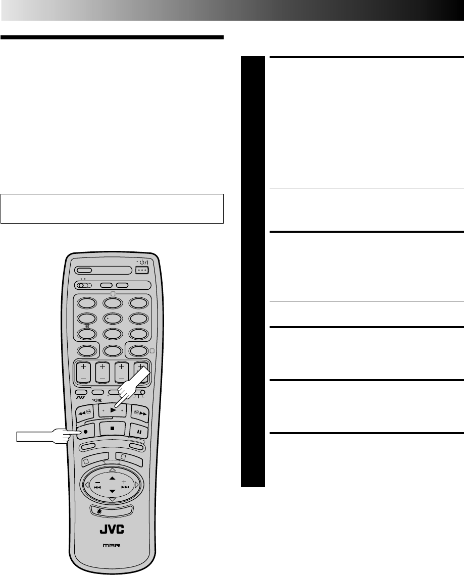
36 EN
EDITING (cont.)
Edit To Or
From Another
Video
Recorder
You can use your video recorder as the source player or the
recording deck.
MAKE CONNECTIONS
1
Connect the player’s 21-pin SCART (AV) connector to
the recorder’s 21-pin SCART (AV) connector as
illustrated on page 37.
When Using Your Video Recorder As The Source
Player . . .
. . . connect its AV1 IN/OUT connector to the recording
deck.
When Using Your Video Recorder As The Recording
Deck . . .
. . . . connect its AV2 IN/DECODER or AV1 IN/OUT
connector to the source player.
●If you are using another recorder with S-Video and
Audio input/output connectors, you can connect
them to this recorder's S-IN/S-OUT and AUDIO IN/
OUT connectors.
SET RECORDING DECK’S
INPUT MODE
2
Set to AUX. When using this recorder as the recording
deck, select the appropriate input mode. Z "To Select
The External Input Mode" on page 35.
●When using the AV2 IN/DECODER connector, make
sure "AV2 SELECT" is set to "AV2" (Z pg. 35).
SET EDIT MODE
3
See "Editing Mode Setting" on page 34.
START SOURCE PLAYER
4
Engage its Play mode.
START RECORDING DECK
5
Engage its Record mode.
NOTES:
●
All necessary cables can be obtained from your dealer.
●
Be sure to set "EDIT" back to "OFF" when you finish editing.
(
Z
pg. 34)
12
45
3
6
8
0
79
2
4
1
3
Set the PAL/MESECAM switch to the appropriate position.
Z pg. 16
PLAY
RECORD
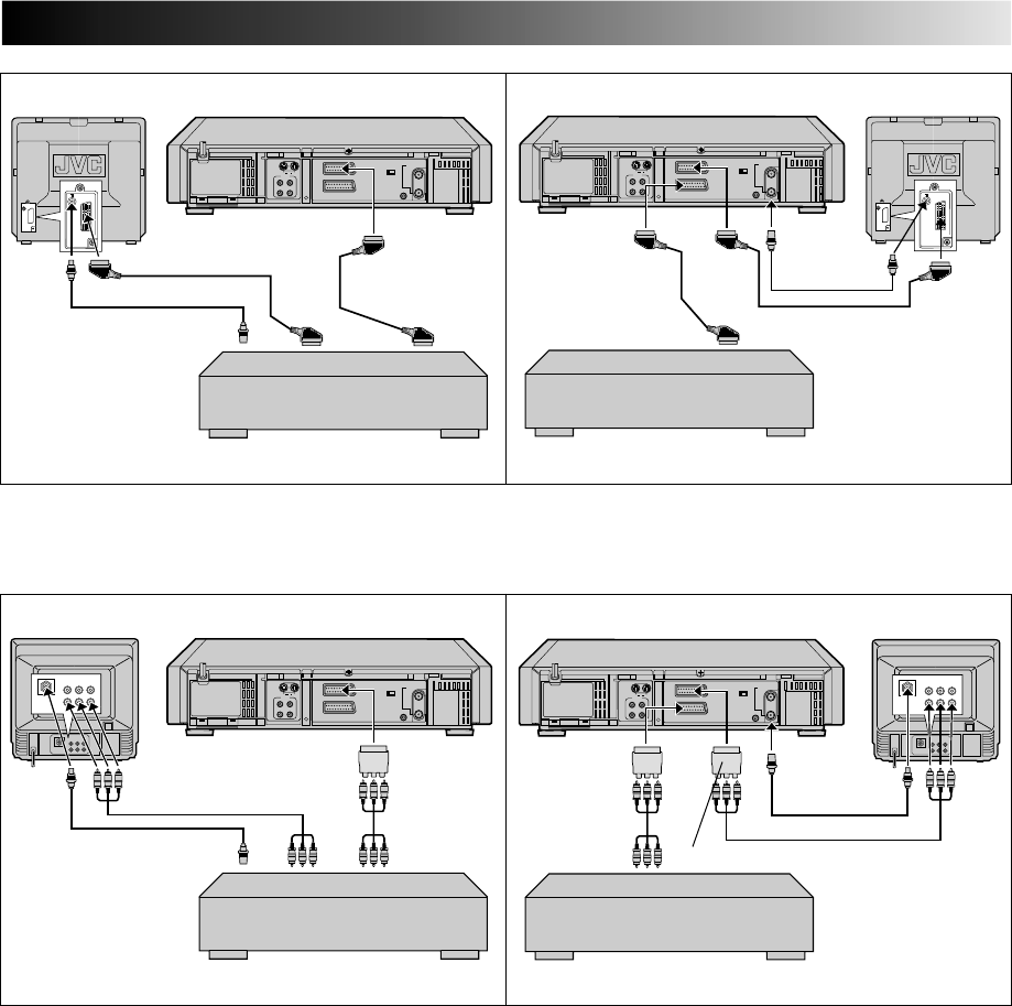
EN 37
Another recorder
RF Cable
(provided)
Another recorder
Recorder
21-pin SCART Cable
(not provided)
Player Your recorder Recorder Your recorderTV Receiver TV Receiver
RF Cable
(provided)
21-pin SCART
Cable
(not provided)
Player
VIDEO
CHAN-
NEL or
AV mode
VIDEO
CHAN-
NEL or
AV
mode
Another recorderAnother recorder
Recorder
Player Recorder Your recorderTV Receiver TV Receiver
Player
Your recorder
VIDEO
CHAN-
NEL or
AV
mode
For Customers in Australia and New Zealand:
When connecting the AV cable, use the input and/or output cable adapter as illustrated below.
Input cable
adapter
(provided)
Output cable
adapter
(provided)
Output cable adapter (provided)
RF Cable
(provided)
Audio/Video Cable
(not provided)
RF Cable
(provided)
VIDEO
CHAN-
NEL or
AV mode
Audio/Video
Cable
(not provided)
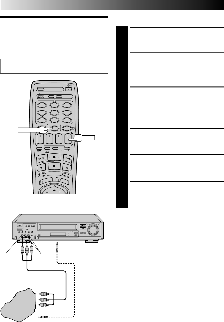
38 EN
You can use a camcorder as the source player and your video
recorder as the recorder.
Edit From A
Camcorder MAKE CONNECTIONS
1
Connect the camcorder’s AUDIO/VIDEO OUT
connectors to the recorder’s front panel AUDIO/VIDEO
input connectors.
●When using a monaural camcorder, connect its
AUDIO OUT connector to the AUDIO IN L input
connector on your recorder.
●When a Master Edit Control-equipped JVC camcorder
is used, the camcorder is capable of controlling the
recorder. Refer to the camcorder’s instruction manual
for operating procedure.
SET RECORDER’S INPUT
MODE
2
Press NUMBER key “0” or TV PROG so that “F-AU”
appears in place of a channel position number.
●Refer to "To Select The External Input Mode" on page
35.
SET EDIT MODE
3
See "Editing Mode Setting" on page 34.
START CAMCORDER
4
Engage its Play mode.
START RECORDER
5
Engage its Record mode.
EDITING (cont.)
Set the PAL/MESECAM switch to the appropriate position.
Z pg. 16
8
••
•
•
••
••
••
•
••
•
•
••
••
••
•
Recorder
AUDIO OUT
VIDEO OUT
EDIT
Player
VIDEO
input AUDIO
input
12
45
3
6
8
0
79
2
4
1
3
NUMBER "0"
Camcorder
Mini-Plug Cable
(not provided)
(JVC camcorder
only)
Audio Cable (provided)
Video Cable (Not provided)
To rear panel PAUSE/
R.A.EDIT connector
TV PROG
NOTE:
Be sure to set "EDIT" back to "OFF" when you finish editing.
(
Z
pg. 34)
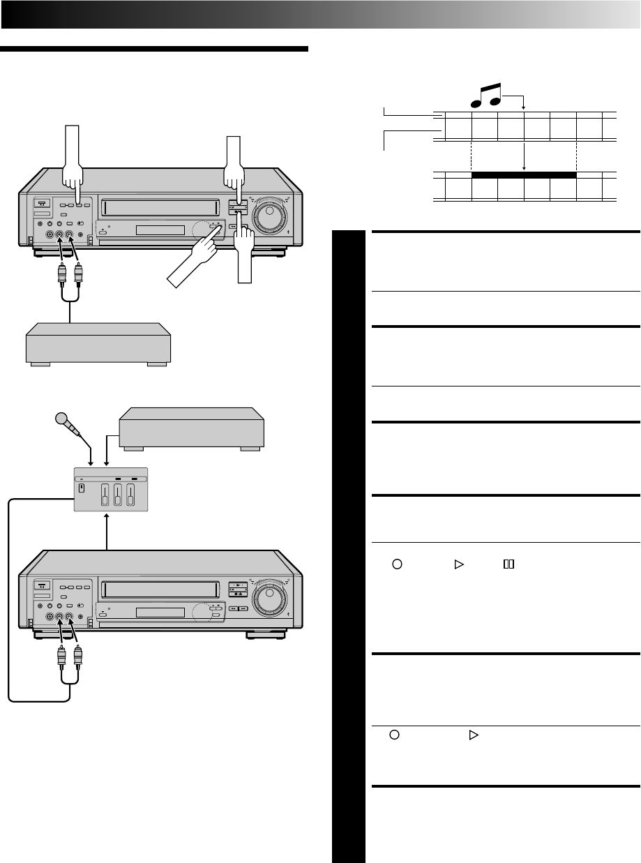
EN 39
Audio dubbing replaces the normal audio sound of a previously
recorded tape with a new soundtrack.
Audio Dubbing
Audio-dubbed tape
Pre-recorded tape
Normal audio track
Video/Hi-Fi audio
track
MAKE CONNECTIONS
1
Connect an audio component to the AUDIO IN L + R
connectors on the recorder's front panel.
●When connecting monaural equipment, use only the
recorder's AUDIO IN L connector.
SET INPUT MODE
2
Press NUMBER key "0" or TV PROG so that "F-AU"
appears in place of a channel number.
●Refer to "To Select The External Input Mode" on page
35.
LOCATE START POINT
3
Press PLAY to start playback of the tape in your
recorder, and press PAUSE when you find the point
where you want to start dubbing.
ENGAGE AUDIO DUBBING
4
Press A. DUB.
●Your recorder enters the Audio Dubbing Pause mode.
(" " blinks, " " and " " light up on the front
display panel.)
●To perform audio dubbbing with audio mixing, press
AUDIO MONITOR on the remote control to select "L
+ R" at this point. *Audio dubbing with audio mixing
is not possible if you're using a monaural audio
component, or if you don't have an audio mixer.
START DUBBING
5
Engage the audio component's Play mode, then press
PLAY to start the tape in your recorder. Audio dubbing
begins at this point.
●" " blinks and " " is displayed on the front
display panel.
●To stop dubbing temporarily, press PAUSE. Press
PLAY to resume dubbing.
END AUDIO DUBBING
6
Press STOP to stop the tape in your recorder, and
engage the audio component's Stop mode.
NOTES:
●
When monitoring the sound during Audio Dubbing, the normal
soundtrack is automatically selected. If you wish to hear the mixed
sound (Hi-Fi + Normal soundtracks), press AUDIO MONITOR on
the remote control to select "L+R+NORM" (
Z
pg. 18).
●
Audio dubbing stops automatically when the counter reaches
"0:00:00", and the recorder enters the Play mode. Check the
counter reading before dubbing.
●
Audio dubbing is also possible using the rear panel AV1 IN/
OUT or AV2 IN connector. When using these connectors,
make sure to select the correct input mode in step 2.
●
Audio dubbing cannot be performed on a cassette that has
had its record safety tab removed.
●
When playing back an audio-dubbed tape, press AUDIO
MONITOR on the remote control to select the soundtrack
you wish to hear (
Z
pg. 18).
8
••
•
•
••
••
••
•
••
•
•
••
••
••
•
8
••
•
•
••
••
••
•
••
•
•
••
••
••
•
A. DUB
PAUSE
STOP
PLAY
Audio mixer
Original sound
AUDIO OUT
CD Player etc.
CD Player etc.
Mixer output
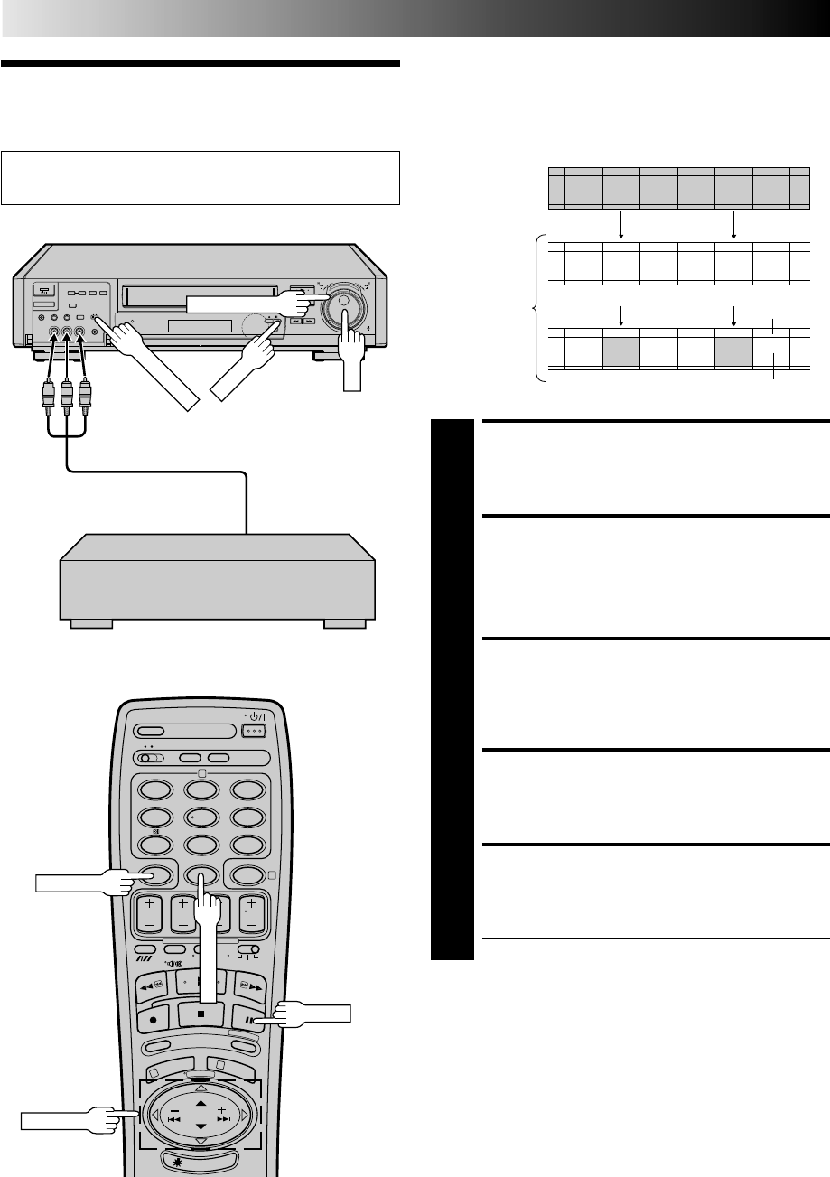
40 EN
Insert editing replaces part of the recorded scene with new
material. Both the picture and Hi-Fi audio soundtrack are
replaced with new ones, while the normal audio soundtrack
remains unchanged. If you wish to change the normal audio
track as well, use the audio dubbing function simultaneously.
Use your video recorder as the recorder.
Insert Editing
EDITING (cont.)
MAKE CONNECTIONS
1
Connect the player's VIDEO OUT and AUDIO OUT
connectors to your recorder's VIDEO IN and AUDIO IN
on the front panel.
SET INPUT MODE
2
Press NUMBER key "0" or TV PROG so that "F-AU"
appears in place of a channel number.
●Refer to "To Select The External Input Mode" on page
35.
LOCATE END POINT
3
Load the recording cassette into your recorder, and play
it back to determine the edit-out point (the end of the
segment to be replaced) using the JOG/TIME SCAN
SHUTTLE controls or PUSH JOG and PAUSE.
RESET THE COUNTER
4
Press C.RESET to change the counter display to "0:00:00".
LOCATE START POINT
5
Determine the edit-in point (the beginning of the
segment to be replaced) using the JOG/TIME SCAN
SHUTTLE controls or PUSH JOG and PAUSE.
●Be sure to engage the Still mode at the edit-in point.
Before insert editing
After insert editing
Source tape
Recorded tape Normal audio
track
Video/Hi-Fi
audio track
8
••
•
•
••
••
••
•
••
•
•
••
••
••
•
Recorder Your recorder
12
45
3
6
8
0
79
2
4
1
3
NUMBER "0"
PUSH JOG
Set the PAL/MESECAM switch to the appropriate position.
Z pg. 16
PAUSE
JOG
TIME SCAN SHUTTLE
Another recorder
Audio/Video signal
Player
C.RESET
PAUSE
PAL/MESECAM
fi
%
fi
%
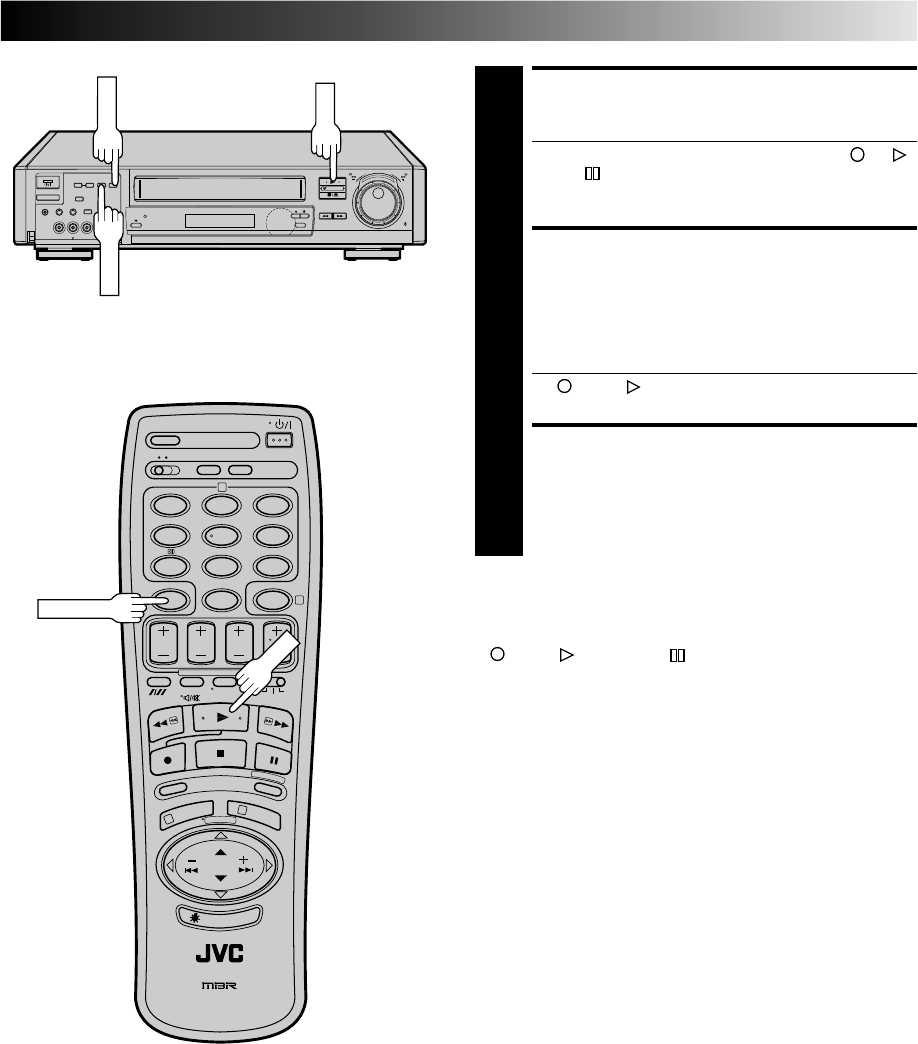
EN 41
ENGAGE INSERT EDITING
6
Press INSERT.
●Your recorder enters the Insert-Pause mode. (" ", " "
and " " light up on the front display panel.)
●The TV screen changes from the still picture to the
input source you are going to record.
START EDITING
7
Load the source cassette and play back the segment
that is to be inserted. When you reach the start of the
section of the source tape that you wish to insert, press
PLAY to start the tape in your recorder; Insert Editing
begins at this point.
●" " and " " are displayed on the front display
panel.
END INSERT EDITING
8
At counter "0:00:00", Insert Editing will stop automati-
cally while the tape continues running in the Play
mode. if you wish to stop Insert Editing before the
specified edit-out point, press C.RESET.
FOR AV INSERT EDITING
If you want to replace the picture, Hi-Fi audio soundtrack and
normal audio soundtrack all at the same time...
In step 6 above, after you press INSERT, press A. DUB also.
(" " and " " blink and " " lights up on the front display
panel.)
12
45
3
6
8
0
79
2
4
1
3
8
••
•
•
••
••
••
•
••
•
•
••
••
••
•
NOTES:
●
Suitable leads can be obtained from your dealer.
●
Insert editing is not possible with cassettes whose safety tab
has been removed.
●
When insert editing is performed on a tape that has been
recorded on another video recorder, the inserted portion may
appear distorted.
●
In insert editing, the recording speed (SP/LP) is determined by
the previous recording to be replaced. If the previous
recording's speed changes within a single edit, the inserted
picture will be distorted at the switching point.
●
A small portion of the recording which precedes an insert edit
may become erased.
●
Insert Editing is also possible using the rear panel AV1 IN/
OUT or AV2 IN connector. When using these connectors,
make sure to select the correct input mode in step 2.
PLAY
INSERT
A. DUB
C.RESET
PLAY
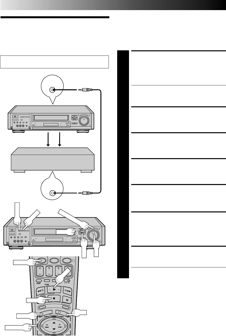
42 EN
PAUSE/
R.A. EDIT
REMOTE
PAUSE
8
••
•
•
••
••
••
•
••
•
•
••
••
••
•
04
1
3
This function makes it easier to create edited videos when your
video recorder is used as the source player in combination with
another JVC video recorder equipped with a Remote PAUSE
Connector. You can pre-program up to 8 scenes or “cuts” for
automatic editing in the sequence you have specified.
You can also perform Random Assemble Editing with a second
non-JVC recorder. Z pg. 43
Random As-
semble Editing
EDITING (cont.)
Set the PAL/MESECAM switch to the appropriate position.
Z pg. 16 MAKE CONNECTIONS
1
Connect your recorder’s AV1 IN/OUT connectors to the
VIDEO IN and AUDIO IN connectors on the recording
deck, and connect your recorder’s PAUSE/R.A. EDIT
connector to the PAUSE connector on the recording
deck.
●If the recording deck doesn’t have a PAUSE connec-
tor, connect to the R.A. EDIT connector instead.
●The Mini-plug cable is a mono 3.5 mm mini-plug to
mono 3.5 mm mini-plug connector.
PREPARE FOR EDITING
2
Insert the cassette to be recorded on into the recorder
and set the recorder's input mode.
LOAD SOURCE CASSETTE
3
Insert the source cassette into your recorder.
SET EDIT MODE
4
See "Editing Mode Setting" on page 34.
START SOURCE PLAYBACK
5
Press PLAY.
ACCESS MAIN MENU
SCREEN
6
Press MENU twice.
ACCESS R.A. EDIT SCREEN
7
Press PUSH JOG %fi to move the highlight bar
(pointer) to "R.A.EDIT", then press OK.
●The screen is superimposed on the video playback in
step 8.
CANCEL
STOP
PLAY
PUSH JOG
8
••
•
•
••
••
••
•
••
•
•
••
••
••
•
PLAY
JOG
IN/OUT
START
TIME SCAN SHUTTLE
STOP
OK
MENU
Player Your recorder
Audio signal Video signal
Another recorder
(w/PAUSE connector)
Recorder
Mini-plug Cable
(Not provided)
EN 43
LOCATE EDIT-IN POINT
8
Find the point on the source
tape from where you want
the edited scene to begin by
pressing PUSH JOG or
using the TIME SCAN
SHUTTLE ring or the JOG
dial, then press IN/OUT.
●The edit-in point is
registered in memory
and appears on the screen.
●You can also perform an Index Search (if index marks
have been previously recorded on the tape at the
desired points) to find the points you want, but this
will result in reduced accuracy.
LOCATE EDIT-OUT POINT
9
Find the point where you
want the edited scene to
end by pressing PUSH
JOG or using the
TIME SCAN SHUTTLE ring
or the JOG dial, then press
IN/OUT.
●The edit-out point is
registered in memory
and appears on the
screen.
●The total time of the
edited scenes is displayed
to the right of "(+)".
●Repeat steps 8 and 9 for
each additional scene.
PREPARE RECORDING DECK
10
Engage its Record-Standby mode.
START R.A. EDIT
11
Press START.
●Automatic editing begins; all the specified scenes are
copied to the recording deck in the order they were
registered.
●The on-screen display remains while your recorder
searches for each scene (blinking cursor indicates
scene currently being searched for), but disappears
during actual editing.
●During scene search, the recording deck automati-
cally enters its Record-Standby mode.
●When all registered scenes have been edited, your
recorder enters the Pause mode, the recording deck
enters its Record-Standby mode, and the cursor blinks
at the next available number.
END R.A. EDIT
12
Press MENU to return to the normal screen, and engage
the Stop mode for your recorder and for the recording
deck.
To Make Corrections . . .
. . . during step 8 or 9, you can cancel registered in and out
points by pressing CANCEL on the remote control. Each time
you press, the preceding point is erased.
●If, for example, you have registered 5 sets of in and out points
and want to reset the first set, you have to press CANCEL until
all points after the first set have been erased. Reenter them
after you've repaired the first set of points.
Memory Capacity
Random Assemble Editing shares
memory space with the recorder's
timer. If there are programs
occupied by timer-recording data,
those spaces cannot be used to
register edit-in and -out points —
meaning you won't be able to edit
8 scenes.
●When all 8 programs are full,
"PROGRAM FULL" appears on the R.A. EDIT screen.
●To cancel a program, see page 32.
RM-V704U Multi-Brand R.A. Edit Controller
(Not provided)
By connecting this controller to your recorder's R.A. EDIT
connector, you can perform Random Assemble Editing in
combination with a second non-JVC video recorder. The controller
is compatible with various major recorder brands. For compatible
systems and availability, please consult your JVC dealer.
NOTE:
Although the RM-V704U is designed to operate the recording
deck, it may not work with some recorders, or may have limited
function capability.
NOTES:
●
You can also monitor the sound when searching for scenes
you want to edit in steps 8 – 9. Since you can hear the
soundtrack during selection, you can avoid abrupt or
unnatural sounding scene-to-scene transitions. The sound that
is heard, however, is not TimeScan Audio.
●
When editing, there may be a discrepancy of about 2 seconds on
the source tape between the locations you chose as edit-in/-out
points and the locations your recorder recognizes as those points.
●
For any scene, the edit-out point must have a counter reading
that is at least 1 second after the corresponding edit-in point. Any
less than 1 second and the edit-out point will not be registered.
●
Since the source recorder prerolls during Random Assemble
Editing, there must be at least 15 seconds worth of recorded
material prior to any edit-in point on the source tape.
●
If the search time for an edit-in point exceeds 5 minutes, the
recording deck enters its Stop mode and editing will not take place.
●
During steps 8 and 9 — if you engage the Pause mode while
registering edit-in and -out points in the R.A. Edit screen, the
characters in the on-screen display may become distorted. This
is normal.
%
fi
=1
2
3
4
5
6
7
8 0:00:00
(+) 0:00:00
[MENU] : EXIT
=1 0:02:23
2
3
4
5
6
7
8 0:02:23
(+) 0:00:00
[MENU] : EXIT
=1 0:02:23 0:02:51
2
3
4
5
6
7
8 0:02:51
(+) 0:00:28
[MENU] : EXIT
fi
%
PROGRAM FULL
0:00:00
(+) 0:00:00
[MENU] : EXIT
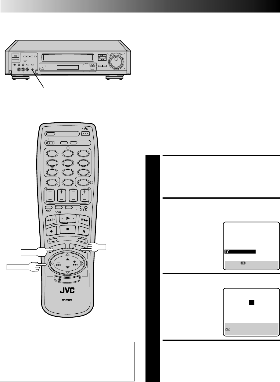
44 EN
INFORMATION ON J TERMINAL
J Terminal (JLIP(Joint Level
Interface Protocol) Connector)
The J Terminal is used to connect the recorder to a personal
computer or similar device to allow computerized control of the
recorder during editing and certain other operations.
Examples:
●Enables Random Assemble Editing of up to 99 segments with
the optional JLIP PLAYER PACK HS-V1EG, using this recorder
as the playback unit.
●Allows you to capture still images from the recorder into a
personal computer with the optional JLIP VIDEO CAPTURE
BOX GV-CB1E.
For further details consult your nearest JVC dealer.
JLIP ID Number
Your recorder has its own JLIP ID number. This ID number must
be unique when your recorder is connected to another device
via its J terminal. The ID Number is preset to "1" at the factory.
You can change this number to any number between "1" and
"99". If it is necessary to change the JLIP ID number perform the
following steps.
12
45
3
6
8
0
79
2
4
1
3
8
••
•
•
••
••
••
•
••
•
•
••
••
••
•
OK
MENU
PUSH JOG
J terminal
ACCESS MAIN MENU
SCREEN
1
Press MENU twice.
ACCESS JLIP ID NO. SET
SCREEN
2
Press PUSH JOG %fi and
move the highlight bar
(pointer) to "JLIP ID NO.
SET", then press OK.
SET JLIP ID NUMBER
3
Press PUSH JOG %fi to
enter the desired ID
number.
RETURN TO NORMAL
SCREEN
4
Press MENU or OK.
MAIN MENU
MODE SET
AUTO CH SET
MANUAL CH SET
GUIDE PROG SET
CLOCK SET
JLIP ID NO. SET
R.A. EDIT
[5∞] =
[MENU] : EXIT
JLIP ID NO. SET
1
CLOCK SET
[5∞] : SELECT
: OK
[MENU] : EXIT
ATTENTION
After you change your recorder's JLIP ID number, control
signal transmission may not work properly. If this happens,
turn off the recorder's power off once, then turn it back on
and try again.
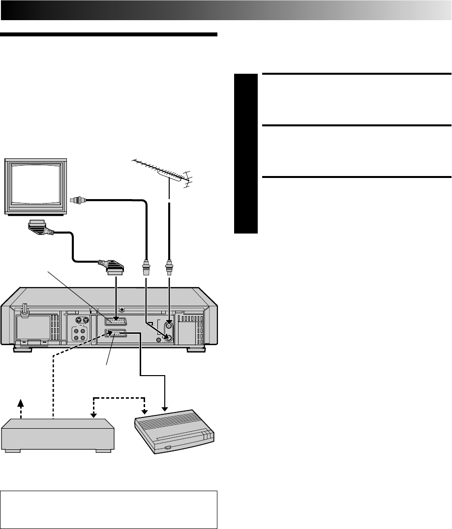
EN 45
The AV2 IN/DECODER connector can be used as an input
terminal for an external decoder (descrambler). Simply connect
a decoder and you can enjoy the variety of programming that is
available through scrambled channels.
SELECT INPUT MODE
1
Set "AV2 SELECT" to "DECODER". (Z pg. 35)
CONNECT DECODER
2
Connect your recorder's AV2 IN/DECODER connector
to the decoder's Euroconnector using a 21-pin SCART
cable.
SET TUNER
3
Perform the procedure as described in "When Receiv-
ing A Scrambled Broadcast" on page 52.
NOTE:
When Connecting A Satellite Tuner . . .
. . . if you don't have a decoder connect the satellite tuner
directly to the video recorder's AV2 IN/DECODER connector.
. . . if you have a decoder, first connect the decoder to the
decoder input of the satellite tuner, then connect the satellite
tuner's output to the recorder's AV2 IN/DECODER connector.
Refer to the instruction book for the satellite tuner and decoder.
. . . set "AV2 SELECT" to "AV2". (
Z
pg. 35)
. . . to view a programme via the satellite tuner, select AU 2
mode by pressing NUMBER key "0" and AV/S SELECT so that
"AU-2" appears on the display panel. (
Z
pg. 35)
SYSTEM CONNECTIONS
Connecting/
Using A
Decoder
TV Receiver
TV Aerial
Cable
Satellite
antenna
Satellite tuner
Decoder
For Customers in Australia and New Zealand:
When connecting the AV cable, use the input and/or output
cable adapter.
AV2 IN/DECODER
AV1 IN/OUT
RF Cable (provided)
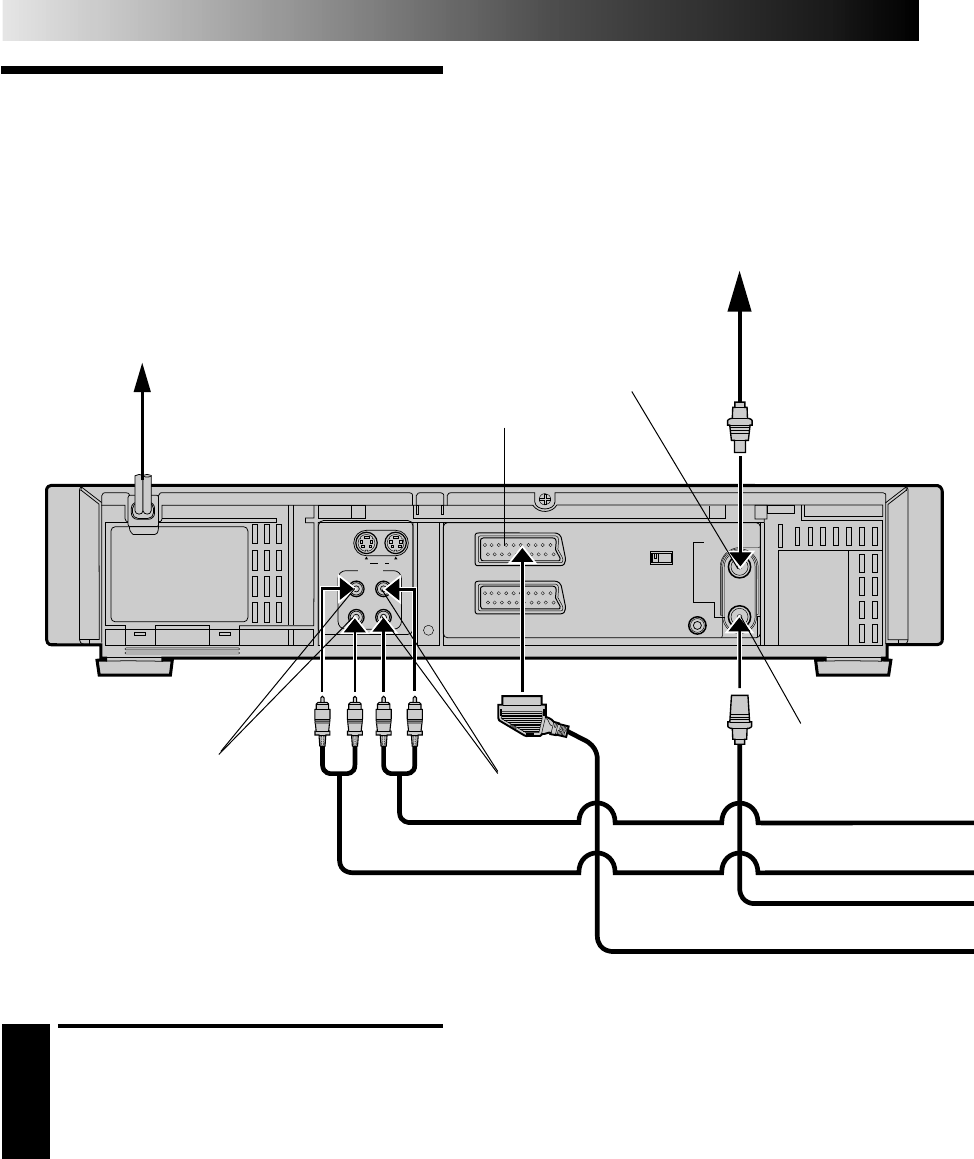
46 EN
AV1 IN/OUT
RF OUT
AV2 IN/DECODER
PAUSE/
R.A.EDIT
AV1 OUT
ANT.IN
COMP.
Y/C
RR
LL
AUDIO
S
IN
IN
OUT
OUT
SYSTEM CONNECTIONS (cont.)
Connecting/
Using A Stereo
System
These instructions enable you to connect your video recorder to
your Hi-Fi stereo system (if you have one) and listen to the
soundtrack through the stereo.
MAKE CONNECTIONS
1
a– Connect the AUDIO IN L and R on your video recorder
to the audio output connectors on your amplifier.
b– Connect the AUDIO OUT L and R connectors on your
video recorder to the AUX IN or TAPE MONITOR
terminals on your stereo system’s receiver or amplifier.
CAUTIONS:
●This recorder has a dynamic range of more than 80 dB with
regards to its Hi-Fi audio capability. It is recommended that
you check the maximum level if you are going to listen to the
Hi-Fi audio signals through a stereo amplifier. A sudden surge
in the input level to the speakers may damage them.
●Some speakers and televisions are specially shielded to
prevent television interference. If both are of the non-shielded
type, do not place the speakers adjacent to the TV set as this
can adversely affect the video playback picture.
NOTES:
●
When connecting your recorder’s audio output connectors to
a stereo amplifier, make sure you connect L and R correctly.
●
If stereo or bilingual TV broadcasts are receivable in your
area, this recorder can record them independently of the TV
set and play them back through the connected stereo system.
●
When listening to sound through the connected stereo system,
turn the TV’s volume down completely.
AUDIO OUT
AUDIO IN
Rear View
Mains outlet
ANT. IN
RF OUT
Aerial or Cable
AV1 IN/OUT
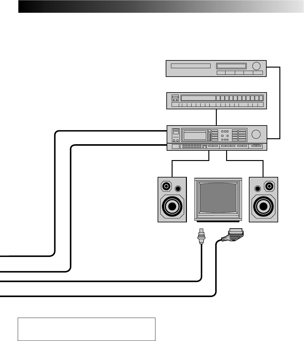
EN 47
I
I
I
I
I
I
I
I
I
I
I
I
I
I
I
I
I
I
I
I
I
I
I
I
I
I
I
I
I
I
I
I
I
I
I
I
I
I
I
I
I
I
I
Speaker
Television
Speaker
FM Tuner
CD Player
Stereo Amplifier
AUDIO OUT
AUX IN or TAPE MONITOR
For customers in Australia and New Zealand:
When connecting the AV cable to your TV, use the input
and output cable adapters.
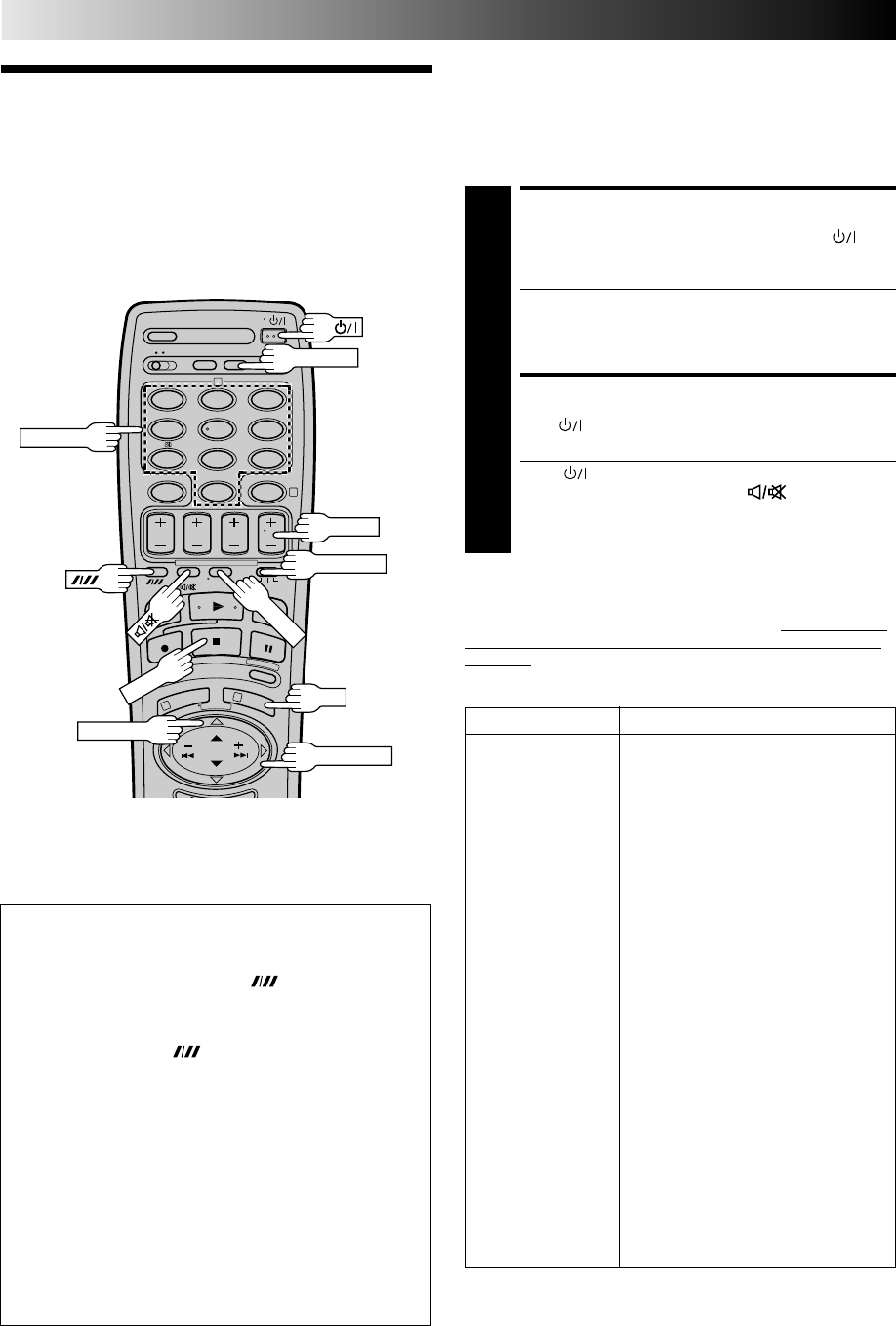
48 EN
TV Multi-
Brand Remote
Control
SPECIAL FEATURES
Your remote control can operate the basic functions of your TV set.
In addition to JVC TVs, other manufacturer’s TVs can also be
controlled by setting the appropriate switch on the remote control.
Before you start . . .
●Turn on the TV using its remote control.
●Set the remote control’s TV/SAT/VCR switch to TV.
TV BRAND NAME CODE
JVC 01, 02, 03, 04
BRANDT 05
NORDMENDE 05
SABA 05
TELEAVIA 05
TELEFUNKEN 05
THOMSON 05
FERGUSON 06
PHILIPS 07
BLAUPUNKT 08
GRUNDIG 08
SONY 09
PANASONIC 10
GRAETZ 11
ITT 11
LUXOR 11
SALORA 11
SELECO 11
MIVAR 12
HITACHI 13
TOSHIBA 14
MITSUBISHI 15
FINLUX 16
NOKIA 17
SHARP 18
FUNAI 20
NEC 22
Control Your TV Using
Additional Buttons
The NUMBER keys on the remote can also be used to select
the TV’s channel by setting the remote control to the TV mode.
1Set the TV/SAT/VCR switch to TV.
2Use the NUMBER keys, and the (Digit Entry)
button, the PUSH JOG button, the DISPLAY button or
the OK button to select the TV’s channel.
●With televisions under Code 01, 02, 03, 04, 06, 07, 09,
10, 13, 14 or 22, the button corresponds to the 1-
digit/2-digit entry switching button (often labelled – /– –)
of your TV’s remote control.
●With televisions under Code 01, 11 or 12, the PUSH JOG
button corresponds to the 10 + button, and the PUSH
JOG button corresponds to the 20 + button of your TV’s
remote control.
●With televisions using Code 12, the DISPLAY button
corresponds to the 30 + button.
●With televisions using Code 09, the OK button corre-
sponds to the ENTER button of your TV’s remote control.
NOTE:
The way these buttons are used is determined by your TV.
Use these buttons as instructed for your TV’s remote control.
fi
%
12
45
3
6
8
0
79
2
4
1
3
OK
STOP
NUMBER
DISPLAY
SET TV BRAND CODE
1
Refer to the chart below. While holding down ,
enter your TV’s brand code using the NUMBER keys,
then press STOP.
●JVC has four codes. If the TV does not function with
one code, try entering another.
●You don’t have to repeat this step until you replace
your remote control’s batteries.
TRY OPERATING TV
2
Press on the remote to turn the TV off. If it goes off,
try other operations.
●The button, TV/VCR button, TV PROG +/–
button, TV VOL %fi button and (Mute) button
on the remote can all be used to operate the TV.
●To return the remote to video recorder control, set its
TV/SAT/VCR switch to VCR.
IMPORTANT
Although the provided remote control unit is compatible with
JVC televisions, as well as many other models, it may not work
with your TV, or in some instances, may have limited function
capability.
TV/VCR
TV PROG
TV/SAT/VCR
TV VOL %fi
PUSH JOG
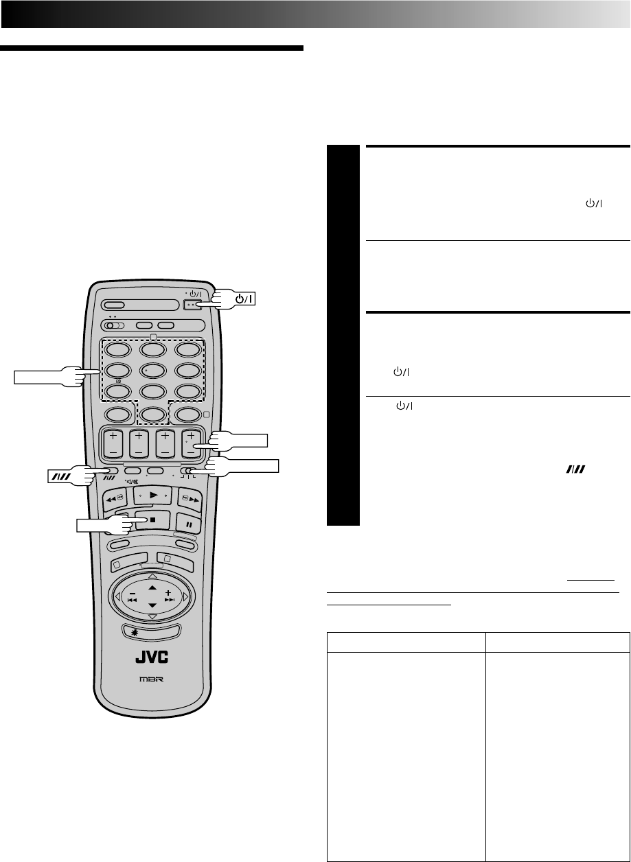
EN 49
Your remote control can operate the basic functions of your
satellite tuner set. In addition to JVC satellite tuners, other
manufacturer’s satellite tuners can also be controlled by setting the
appropriate switch on the remote control.
Before you start . . .
●Turn on the satellite tuner using its remote control.
●Set the remote control’s TV/SAT/VCR switch to SAT.
Satellite
Tuner Multi-
Brand Remote
Control
SET SATELLITE TUNER
BRAND CODE
1
Refer to the chart below. While holding down ,
enter your satellite tuner’s brand code using the
NUMBER keys, then press STOP.
●Some satellite tuner brands have more than one code.
If the satellite tuner does not function with one code,
try entering another.
●You don’t have to repeat this step until you replace
your remote control’s batteries.
TRY OPERATING SATELLITE
TUNER
2
Press on the remote to turn the satellite tuner off. If
it goes off, try other operations.
●The button, TV PROG +/– button, NUMBER
buttons on the remote can all be used to operate the
satellite tuner.
●The NUMBER buttons will not work with JVC satellite
tuners using code 13.
●With satellite tuners using Code 16, the button
corresponds to the ENTER button of your satellite
tuner’s remote control.
●To return the remote to video recorder control, set its
TV/SAT/VCR switch to VCR.
IMPORTANT
Although the provided remote control unit is compatible with
JVC satellite tuners, as well as many other models, it may not
work with your satellite tuner, or in some instances, may have
limited function capability.
SATELLITE TUNER BRAND CODE
JVC 13, 14
AMSTRAD 01, 02, 03, 04
SIEMENS 05
GRUNDIG 05, 06
KATHREIN 05, 11, 12
PACE 06, 08
PHILIPS 07
ITT 09
NOKIA 09
SKYMASTER 10
RFT 10
MASPRO 11
BT 13
PANASONIC 15
JERROLD 16
12
45
3
6
8
0
79
2
4
1
3
STOP
NUMBER
TV PROG
TV/SAT/VCR
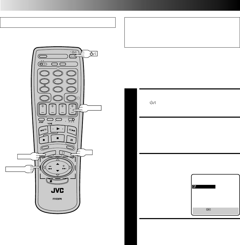
50 EN
Turn on the TV and select the VIDEO channel (or AV mode). IMPORTANT
Perform the following steps only if auto channel set has not
been set correctly by Auto Set Up function (Z pg. 6) or if
you have moved to a different area or if a new station starts
broadcasting in your area.
TUNER SET
Your recorder needs to memorise all necessary stations in
channel positions in order to record TV programmes. Auto
Channel Set automatically assigns all receivable stations in your
area so that you can call them up with the TV PROG buttons
without going through any vacant channels.
Auto Channel Set
MAIN MENU
MODE SET
AUTO CH SET
MANUAL CH SET
GUIDE PROG SETT
CLOCK SET
JLIP ID NO. SET
R.A. EDIT
[5∞] =
[MENU] : EXIT
TURN ON THE RECORDER
1
Press .
ACCESS MAIN MENU
SCREEN
2
Press MENU twice.
ACCESS COUNTRY SET
SCREEN
3
Press PUSH JOG%fi to
move the highlight bar
(pointer) to "AUTO CH
SET", then press OK.
SELECT COUNTRY
4
Press PUSH JOG%fi to move the highlight bar (pointer)
to your country's name, then press OK. The Language
Set screen appears.
12
45
3
6
8
0
79
2
4
1
3
OK
MENU
PUSH JOG
TV PROG
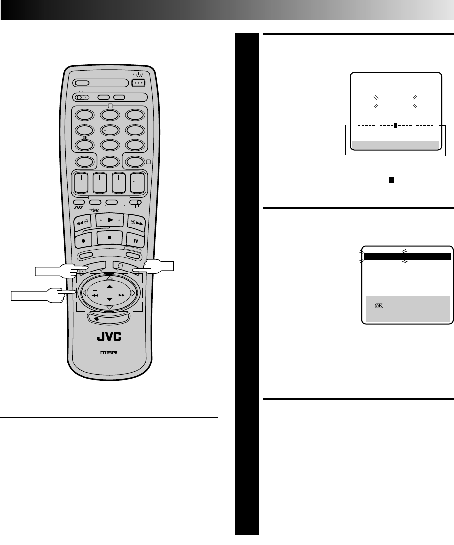
EN 51
12
45
3
6
8
0
79
2
4
1
3
OK
PUSH JOG
AUTO SET
PLEASE WAIT
[MENU] : EXIT
0
+++
PERFORM AUTO CHANNEL
SET
5
Press PUSH JOG%fi to
move the highlight bar
(pointer) to the
language of your
choice , then press OK
to initiate Auto
Channel Set.
●The Auto Set screen
appears, and
remains on screen
while the recorder searches for receivable stations. As
Auto Channel Set progresses, the " " mark on the
screen moves from left to right. Wait until the screen
as shown in step 6 appears.
VIEW CONFIRMATION
SCREEN
6
The stations your recorder
located appear on a
Confirmation screen —
channel positions (PR),
channels (CH) and station
names (ID– Z pg. 54). To
view the next page of the
listing, press PUSH
JOG%fi . The blueback
screen and the program
currently being broadcast by the
blinking station appear alternately for 5 seconds each.
● The stations located in the selected country appear at
the top of the list.
● The Guide Program numbers will also be set
automatically during Auto Channel Set.
RETURN TO NORMAL
SCREEN
7
Press MENU.
●Depending on the reception conditions, the stations
may not be stored in order, and the station names
may not be stored correctly.
●Using the Confirmation screen, you can skip or add
channel positions, enter station names and perform
other operations. Refer to pages 52 – 53 for the
procedures.
●For information on scrambled broadcasts, refer to
page 52.
Beginning End
MENU
IMPORTANT
● Depending on the reception conditions, the station names
may not be stored correctly, and auto Guide Program
Number Set may not work properly. If the Guide Program
numbers are not set properly, SHOWVIEW timer recording
(Z pg. 28) will not work correctly; be sure to check if the
Guide Program numbers have been set correctly
(Z pg. 12, "SHOWVIEW Setup").
●Since your video recorder memorizes all detected
stations even if the reception condition is poor, some of
those stored stations may produce a noisy picture. To
delete those stations, Z "Delete A Channel" on page 52.
5
5
PR CH ID PR CH ID
01 25 ARD 08 C26 E-SP
02 C08 SKY1 09 55
WEST
03 10 ZDF 10 C24 SAT1
04 C65 RAI1 11 C23 OSF
05 C31 BBC1 12 C25 ESPN
06 C32 BBC2 13 C37 CNN
07 C33 3SAT 14 C35
[5∞ ]
= : EDIT
= [CANCEL] : DELETE
[MENU] : EXIT
5
5
C: Cable
%
%
NOTE:
Fine tuning is performed automatically during Auto Channel
Set. If you want to perform it manually, refer to page 53.

52 EN
Storing Channels Manually
Store channels that were not stored during Auto Set Up (Z pg. 6)
or Auto Channel Set (Z pg. 50).
* In Australia and New Zealand, channels cannot be stored
properly even though the following procedure is performed.
TUNER SET (cont.)
Change Station Channel
Position
SELECT ITEM
1
Press PUSH JOG%fi until the item you want to
move begins blinking. Then press OK and the station
name (ID) and its channel (CH) number begin blinking.
SELECT NEW POSITION
2
Press PUSH JOG%fi to move the station to the new
channel position, then press OK.
Example: If you moved the station in position 3 to
position 7, the stations originally in positions 4–7 each
move up one space.
●Repeat steps 1 and 2 as necessary.
CLOSE CONFIRMATION
SCREEN
3
Press MENU.
%
%
%
%
Perform steps 1 and 2 of the previous procedure to access
the Confirmation screen before continuing.
Delete A Channel
SELECT ITEM
1
Press PUSH JOG%fi until the item you want to
delete begins blinking.
DELETE CHANNEL
2
Press CANCEL.
●The item directly beneath the cancelled one moves
up one line.
●Repeat steps 1 and 2 as necessary.
CLOSE CONFIRMATION
SCREEN
3
Press MENU.
%
%
ACCESS MAIN MENU
1
Press MENU twice.
ACCESS CONFIRMATION
SCREEN
2
Press PUSH JOG%fi to move the highlight bar (pointer)
to “MANUAL CH SET”, then press OK. The Confirma-
tion screen appears.
SELECT POSITION
3
Press PUSH JOG%fi until an open position in
which you want to store a channel begins blinking,
then press OK. The Manual Ch. Set screen appears.
INPUT CHANNEL
4
The number "01" appears blinking beneath "CH".
Press the NUMBER keys to input the channel number
you want to store.
●For fine tuning adjustment, press PUSH JOG until
the item beneath "CH" begins blinking, then press
PUSH JOG%fi. While tuning, “F+” or “F–” appears.
●If necessary, to change the band between CH(regular)
and CC(cable), press PUSH JOG until CH or CC is
blinking, then press PUSH JOG %fi to select the
band.
●When storing a channel that sends scrambled
broadcasts, press PUSH JOG until "OFF" (Decoder
setting) blinks, then press PUSH JOG%fi to set
"DECODER" to "ON" ("OFF" is the default setting).
ENTER NEW CHANNEL
INFORMATION
5
Press OK and the Confirmation screen appears.
●Repeat steps 3 through 5 as necessary.
CLOSE CONFIRMATION SCREEN
6
Press MENU.
●To input the station name, see page 53.
●To change positions, see "Change Station Channel
Position" (at right).
When Receiving A Scrambled Broadcast
Make sure that "AV2 SELECT" is set to "DECODER" (Z pg. 35).
1– Perform steps 1 and 2 above.
2– Press PUSH JOG%fi to select the position of the
channel broadcasting the scrambled programmes, then
press OK three times.
3– Press PUSH JOG until "OFF (Decoder setting)" begins
blinking, and set it to "ON" by pressing PUSH JOG%fi.
4– Press OK to access the Confirmation screen.
●Repeat steps 2 – 4 for each additional channel.
5– Press MENU.
%
%
%
%
fi
%
%
fi
%

EN 53
Fine-Tuning Channels
Already Stored
Perform steps 1 and 2 of "Storing Channels Manually" on
page 52 to access the Confirmation screen before continuing.
Set Stations (A)
SELECT ITEM
1
Press PUSH JOG%fi until the item you want begins
blinking. Then press OK twice and the station’s name
(ID) begins blinking.
SELECT NEW STATION
2
Press PUSH JOG%fi until the new station’s name (ID)
you want to store begins blinking.
Registered station names (Z pg. 54) appear as you
press PUSH JOG%fi.
SWITCH STATIONS
3
Press OK.
●Repeat steps 1 through 3 as necessary.
CLOSE CONFIRMATION
SCREEN
4
Press MENU.
%
%
NOTE:
First perform step 1 of the above procedure.
SELECT STATION NAME
CHARACTER
2
Press PUSH JOG and the first letter of the station
name begins blinking.
ENTER NEW CHARACTER
3
Press PUSH JOG%fi to cycle through the characters
(A–Z, 0–9, –, *, +, (space)) and stop when the
desired one is indicated, then press PUSH JOG to
enter. Enter the remaining characters the same way
(maximum of 4).
After entering all characters, press OK.
●Repeat steps 1 through 3 as necessary.
●If you make a mistake, press PUSH JOG until the
incorrect character begins blinking. Then enter the
correct character by pressing PUSH JOG%fi .
CLOSE CONFIRMATION
SCREEN
4
Press MENU.
%
%
%
]
SELECT CHANNEL TO
FINE-TUNE
1
Press PUSH JOG%fi until the channel you want to
tune begins blinking.
ACCESS MANUAL CH. SET
SCREEN
2
Press OK three times. The Manual Ch. Set screen
appears.
PERFORM TUNING
3
Press PUSH JOG%fi until the picture is its clearest.
Then press OK.
●The Confirmation screen appears.
●Repeat steps 1 through 3 as necessary.
CLOSE CONFIRMATION
SCREEN
4
Press MENU.
%
%
Set Stations (B)

54 EN
TUNER SET (cont.)
TV Station And ID List
ID* STATION NAME
1000 TV1000
3SAT 3SAT
ADLT ADULT
ANT3 ANTENA3
ARD ARD
ARTE ARTE
BBC BBC GROUP
BBC1 BBC1
BBC2 BBC2
BR3 BAYERN3
C+ CANAL PLUS
C1 PORTUGUSES
CAN5 CANALE5
CH4 CHANNEL4
CH5 CHANNEL5
CHLD CHILD
CINE CINEMA
CLUB TELECLUB
CMT CMT
CNN CNN
CSUR ANDALUCIA
DISC DISCOVERY
DR DR TV
DRS DRS
DSF DSF
ETB1 ETB1
ETB2 ETB2
EURO EURONEWS
EUSP EUROSPORTS
FEMM FEMMAN
FILM FILM
FNET FILMNET
FR2 France2
FR3 France3
GALA GALAVISION
HR3 HESSEN3
INFO INFO-KANAL
ITA1 ITALIA1
ITA7 ITALIA7
ITV ITV
JSTV JSTV
KA2 KA2
KAB1 KABEL1
KAN2 KANAL2
LOCA LOCAL
M6 M6
MBC MBR
MCM MCM
MDR MDR
MOVE MOVIE
MTV MTV
MTV3 MTV3
N3 NORD3
N-TV N-TV
NBC NBC SUPER
NDR3 NDR3
NED1 NED1
NED2 NED2
NED3 NED3
NEWS
NICK NICKELODEON
NRK NRK
NRK2 NRK2
ODE ODEON
ORF1 ORF1
ID* STATION NAME
ORF2 ORF2
ORF3 ORF3
OWL3 OWL3
PREM PREMIERE
PRO7 PRO7
RAI1 RAI1
RAI2 RAI2
RAI3 RAI3
RET4 RETE4
21 TELE21
RTBF RTBF1 or 2
RTL RTL
RTL2 RTL2
RTL4 RTL4
RTL5 RTL5
RTP RTP
S4 SCHWEIZ4
SAT1 SAT1
SBS SBS
SHOW SHOW
SIC SOCIEDADE
SKY SKY CHANNEL
SKYN SKY NEWS
SPRT SPORT
SRTL SUPER RTL
STAR STAR-TV
SVT1 SVT1
SVT2 SVT2
SW3 SUEDWEST3
TCC TCC
TELE TELE
TEL5 TELE5
TF1 TF1
TM3 TM3
TMC TELEMONTECARLO
TNT TNT INT
TRT TRT INT
TSI TSI
TSR TSR
TV1 BRTN TV1
TV2 BRTN TV2
TV3 TV3
TV4 TV4
TV5 TV5
TV6 TV6
TVE1 TVE1
TVE2 TVE2
TVG TV GALICIA
TVI TV INDEPENDENT
TVN TV NORGE
VCR VIDEO
VERO VERONICA
VH-1 VH-1
VIVA VIVA
VIV2 VIVA2
VMTV VIDEO MUSIC
VOX VOX
VT4 VT4
VTM VTM
WDR1 West1
WDR3 West3
YLE1 YLE1
YLE2 YLE2
ZDF ZDF
ZTV ZTV
* The "ID" abbreviation is what is shown on-screen in lieu of the
station name. The "ID" abbreviation is listed in the Confirma-
tion screen and is displayed on the TV screen when the
recorder is tuned to a different station.
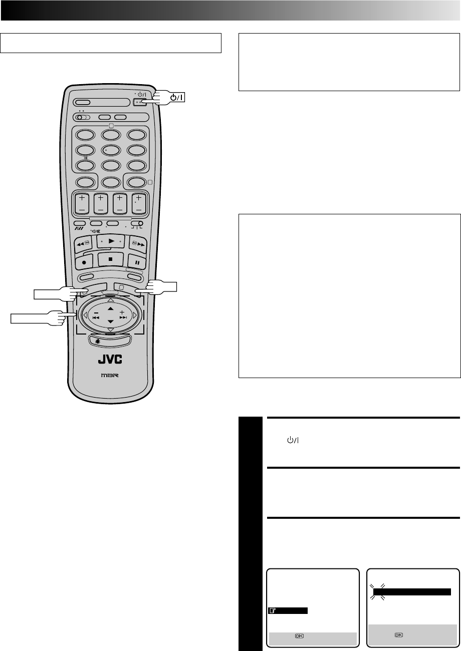
EN 55
Turn on the TV and select the VIDEO channel (or AV mode).
CLOCK SET
12
45
3
6
8
0
79
2
4
1
3
PUSH JOG
OK
IMPORTANT
Perform the following steps only if auto clock set has not
been set correctly by Auto Set Up function (Z pg. 6) or
Auto Channel Set (Z pg. 50) or if the recorder's memory
backup has expired.
MENU
If you performed Auto Set Up or Auto Channel Set without ever
having set the clock previously, the recorder’s built-in clock is
also set automatically. The Auto and Manual clock setting
procedures are necessary when . . .
– a power outage of more than 60 minutes occurs.
– the tuner has been set manually.
– the user desires to set the clock slightly ahead of the actual
time.
– the clock was not set even after Auto Set Up or Auto
Channel Set was performed.
Whether you perform Auto or Manual clock setting, you can
use the convenient Just Clock function.
Just Clock
The Just Clock function provides accurate time keeping
through automatic adjustments at regular intervals, by
reading data from a PDC signal.
The Just Clock option appears in the Clock Set and Auto
Clock screens, and can be set “ON” or “OFF” (the default
setting is “OFF”). Press OK until the Just Clock setting
begins blinking, then press PUSH JOG%fi to change the
setting.
IMPORTANT: If you turn off Just Clock, the accuracy of
your recorder’s built-in clock may be reduced, which could
adversely effect timer recording. We recommend you to
keep Just Clock on. In cases where the clock setting data
from a PDC signal is incorrect, however, you are advised to
keep Just Clock set to "OFF".
* Just Clock does not work in areas where no TV station
transmits PDC signals.
Both Auto and Manual clock setting procedures begin from step 4.
CONTINUED ON NEXT PAGE.
TURN THE RECORDER ON
1
Press .
ACCESS MAIN MENU SCREEN
2
Press MENU twice.
ACCESS CLOCK SET SCREEN
3
Move the highlight bar (pointer) to "CLOCK SET" by
pressing PUSH JOG %fi, then press OK. The Clock Set
screen appears.
Preparation
MAIN MENU
MODE SET
AUTO CH SET
MANUAL CH SET
GUIDE PROG SET
CLOCK SET
JLIP ID NO. SET
R.A. EDIT
[5∞] =
[MENU] : EXIT
CLOCK SET
TIME DATE YEAR
0: 00 01 . 01 00
JUST CLOCK : OFF
TV PR. : 1
[ ] : AUTO CLOCK
[5∞] =
[MENU] : EXIT
5
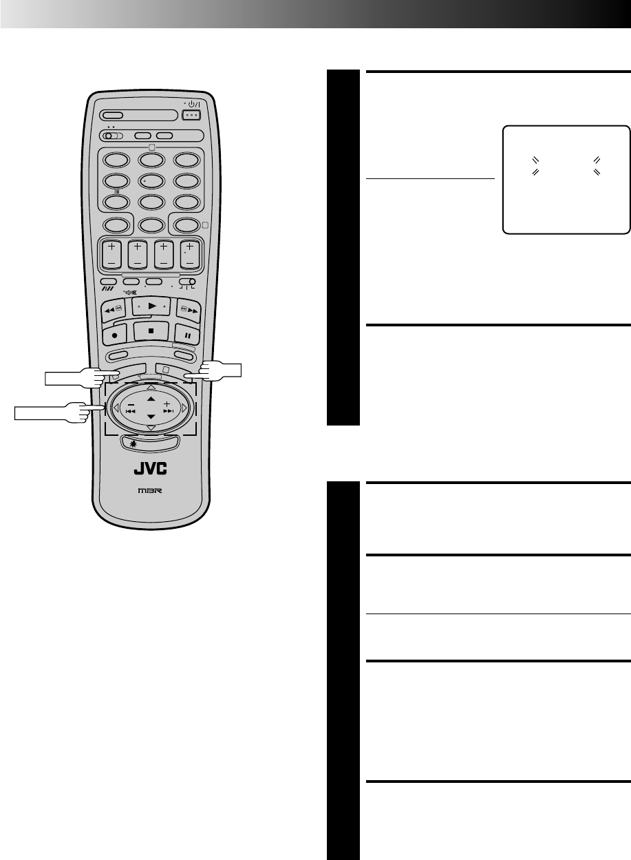
56 EN
CLOCK SET (cont.)
SET CLOCK
AUTOMATICALLY
4
At the Clock Set screen,
press PUSH JOG . The
Auto Clock screen appears
and clock setting begins.
● If "TV PR." isn't set to the
channel position on
which Auto Clock data
is received, "ERROR"
appears, and then the
screen from step 3 reappears. To set "TV PR.", press
OK to place the pointer next to it, then cycle through
the numbers by pressing PUSH JOG%fi until the
number representing the channel position in which
the station transmitting clock setting data is stored
appears.
RETURN TO NORMAL
SCREEN
5
Once clock setting is completed, press MENU to return
to the normal screen.
Auto Clock Set
%
NOTES:
●
Auto Clock and Just Clock require a PDC signal, and will not
operate with a VPS signal.
●
Just Clock (when set to "ON") enables adjustment of the
recorder's built-in clock every hour on the hour, except for
23:00, 0:00, 1:00 and 2:00.
●
Just Clock is not effective when . . .
– the recorder’s power is on (unless the recorder is tuned to
the same channel position selected in the Clock Set screen).
– the recorder is in the Timer mode.
– a difference of more than 3 minutes exists between the
built-in clock’s time and the actual time.
●
If Just Clock is set to "ON", the recorder’s clock is automati-
cally adjusted at the start/end of Summer Time.
●
Auto clock setting and Just Clock may not function properly
depending on the reception condition.
●
During Manual clock setting, if the day and month data are
invalid (such as 31st April), the month digits are cleared
automatically and the day digits begin blinking. Input the
correct data.
●
If, in step 4 of the Manual clock setting procedure, the year
digits are automatically cleared and the day digits begin
blinking, it is possible that you have input 29th February for a
non-leap year. Input the correct data.
12
45
3
6
8
0
79
2
4
1
3
PUSH JOG
OK
MENU
AUTO CLOCK
PLEASE WAIT
JUST CLOCK : OFF
TV. PR : 1
SET DATE AND TIME
4
Press PUSH JOG%fi to set the hour, then press OK. The
“minutes” display begins blinking. Repeat the proce-
dure to set the minutes, day, month and year.
SET JUST CLOCK
5
The default setting is “OFF”. Set as desired by pressing
PUSH JOG%fi, then press OK.
●If you set to “OFF”, you can disregard the next step as
you won’t be able to receive regular clock adjust-
ments.
SET CLOCK DATA SOURCE
CHANNEL POSITION
6
The recorder is preset to receive clock setting and
adjustment data from channel position 1. Press PUSH
JOG%fi to set the channel position to the number
representing the station transmitting clock setting data,
then press OK.
START CLOCK OPERATION
7
Press MENU.
Manual Clock Set

EN 57
TROUBLESHOOTING
Before requesting service for a problem, use this chart and see if you can repair the trouble yourself. Small problems are often easily
corrected, and this can save you the trouble of sending your video recorder off for repair.
POSSIBLE CAUSE
●The mains power cord is discon-
nected.
●“‰“ is displayed on the display
panel with Auto Timer set to "OFF".
SYMPTOM
1. No power is applied to the
recorder.
2. The clock is functioning properly,
but the recorder cannot be powered.
CORRECTIVE ACTION
Connect the mains power cord.
Press the TIMER button to turn the
“‰“ indicator off.
SYMPTOM
1. The tape does not run during
recording.
2. The tape stops during rewind or
fast-forward.
3. The tape will not rewind or fast-
forward.
CORRECTIVE ACTION
Press PLAY to turn the “^“ indicator
off.
Press C.MEMORY to deactivate the
Counter Memory function and turn
the “M“ indicator off.
Check the cassette.
SYMPTOM
1. The playback picture does not
appear while the tape is running.
2. Noise appears during normal
playback.
3. Noise appears during slow-motion
playback.
4. Noise appears during still play-
back.
5. Breaks are noticeable in Hi-Fi
soundtrack
6. The playback picture is blurred or
interrupted while TV broadcasts are
clear.
POSSIBLE CAUSE
●If you’re using the RF OUT connec-
tion . . .
. . . the TV receiver’s channel selector
is not set to the VIDEO channel.
. . . the recorder's VIDEO channel
has not been correctly set.
●If you’re using the AV or S-VIDEO
connection, the TV receiver is not set
to the AV mode.
●The automatic tracking mode is
engaged.
●The automatic tracking mode is
engaged.
●Automatic tracking is engaged.
●The video heads may be dirty.
CORRECTIVE ACTION
If you are using the RF OUT connec-
tion . . .
. . . set the TV receiver to the VIDEO
channel. (Z pg. 10)
. . . Perform "Video Channel Set"
(Z pg. 10)
If you are using the AV or S-VIDEO
connection, set the TV to its AV
mode.
Try manual tracking. (Z pg. 16)
Try manual tracking. (Z pg. 16)
Press TV PROG + or – a few times to
remove the noise bars from the screen.
Engage and adjust tracking manually.
(Z pg. 16)
Consult your JVC dealer.
POSSIBLE CAUSE
●“^“ is displayed on the display
panel.
●“M“ is displayed on the display
panel.
●The tape is already fully rewound or
fast-forwarded.
CONTINUED ON NEXT PAGE.
CORRECTIVE ACTION
Insert a cassette, or using adhesive
tape, reseal the slot where the tab
was removed.
Set to the desired channel.
Confirm that the source is properly
connected.
Confirm that all units’ power switches
are turned on.
Set the input mode to “AU”.
POSSIBLE CAUSE
●There is no cassette loaded, or the
cassette loaded has had its Record
Safety tab removed.
●“AU” has been selected as the input
mode.
●The source (another video recorder,
camcorder) has not been properly
connected.
●All necessary power switches have
not been turned on.
●The input mode is not correct.
SYMPTOM
1. Recording cannot be started.
2. TV broadcasts cannot be recorded.
3. Tape-to-tape editing is not possible.
RECORDING
PLAYBACK
TAPE TRANSPORT
POWER

58 EN
Confirm that the camcorder is
properly connected.
Set the input mode to “AU”.
●The camcorder has not been
properly connected.
●The input mode is not correct.
4. Camcorder recording is not
possible.
TROUBLESHOOTING (cont.)
TIMER RECORDING
CORRECTIVE ACTION
Re-perform the clock and/or timer
settings.
Press TIMER and confirm that “‰“ is
displayed on the display panel.
Timer programming can’t be
performed while a timer recording is
in progress. Wait until it finishes.
Load a cassette with the Record
Safety tab intact, or cover the hole
using adhesive tape.
Remove the cassette and cover the
hole with adhesive tape, or insert a
cassette with the Record Safety tab
intact.
Check the programmed data and re-
program as necessary, then press
TIMER again.
The programme may not have been
recorded in its entirety. Next time
make sure you have enough time on
the tape to record the entire
programme.
Refer to "Guide Program Number Set"
and re-perform the procedure
(Z pg. 12).
SYMPTOM
1. Timer recording won’t work.
2. On-screen timer programming is
not possible.
3. “‰“ and “]“ on the display
panel won’t stop blinking.
4. The cassette is automatically
ejected, and “‰“ and “]“ on the
display panel won’t stop blinking.
5. “‰“ blinks for 10 seconds and the
Timer mode is disengaged.
6. The cassette is automatically
ejected, the power shuts off and
“‰“ and “]“ won’t stop
blinking.
7. SHOWVIEW does not timer-record
properly.
POSSIBLE CAUSE
●The clock and/or the timer have
been set incorrectly.
●The timer is not engaged.
●Timer recording is in progress.
●The timer is engaged but there’s no
cassette loaded.
●The loaded cassette has had its
Record Safety tab removed.
●TIMER has been pressed when there
are no programs in memory, or the
timer record information has been
programmed incorrectly.
●The end of the tape was reached
during timer recording.
●The recorder’s channel positions
have been set incorrectly.
OTHER PROBLEMS
CORRECTIVE ACTION
Position the camcorder so its
microphone is away from the TV.
Turn the TV’s volume down.
If you need the skipped channels,
restore them (Z pg. 52).
Press PAUSE to pause the recording,
change channels, then press PLAY to
resume recording.
Set the switch to the correct position.
Perform manual setting again.
Connect the TV aerial cable to the
recorder properly and turn off the
recorder power once, then turn the
recorder power back on again. The
recorder will try Auto Set Up again
(Z pg. 6).
SYMPTOM
1. Whistling or howling is heard from
the TV during camcorder record-
ing.
2. When scanning channels, some of
them are skipped over.
3. The channel cannot be changed.
4. The remote control won’t operate
the TV or satellite tuner.
5. Channel settings that were made
manually seem to have changed or
disappeared.
6. No channels are stored in the
recorder's memory.
POSSIBLE CAUSE
●The camcorder’s microphone is too
close to the TV.
●The TV’s volume is too high.
●Those channels have been desig-
nated to be skipped.
●Recording is in progress.
●The TV/SAT/VCR switch is in the
wrong position.
●After the manual settings were
made, Auto Channel Set was
performed.
●The TV aerial cable was not
connected to the recorder when
Auto Set Up was performed.

EN 59
QUESTIONS AND ANSWERS
PLAYBACK
Q. What happens if the end of the tape is reached
during playback or search?
A. The tape is automatically rewound to the beginning.
Q. Can the video recorder indefinitely remain in the
still mode?
A. No. It stops automatically after 5 minutes to protect
the heads.
Q. When returning from multi-speed search to normal
playback, the picture is disturbed. Should I be
concerned about this?
A. No, it is normal.
Q. Other than preventing further recording, what effect
does removing the Record Safety tab have?
A. It disables marking of index codes.
Q. Sometimes, during Index Search, the video recorder
can’t find the programme I want to see. Why not?
A. There may be index codes too close together.
RECORDING
Q. When I pause and then resume a recording, the end
of the recording before the pause is overlapped by
the beginning of the continuation of recording. Why
does this happen?
A. This is normal. It reduces distortion at the pause and
resume points.
Q. Can the video recorder indefinitely remain in the
Record-Pause mode?
A. No. The video recorder goes to its Stop mode auto-
matically after 5 minutes to protect the heads.
Q. What happens if the tape runs out during recording?
A. The video recorder automatically rewinds it to the
beginning.
TIMER RECORDING
Q. " " and "‰" remain lit on the display panel. Is
there a problem?
A. No. This is a normal condition for a timer recording in
progress.
Q. Can I program the timer while I’m watching a tape
or a TV broadcast?
A. You won’t see the picture as it is replaced by the on-
screen menu, but the audio from the program or tape
you’re viewing can be heard.
ATTENTION:
This recorder contains microcomputers. External electronic noise or interference could cause malfunctioning. In such cases,
switch the recorder off and unplug the mains power cord. Then plug it in again and turn the recorder on. Take out the cassette.
After checking the cassette, operate the unit as usual.
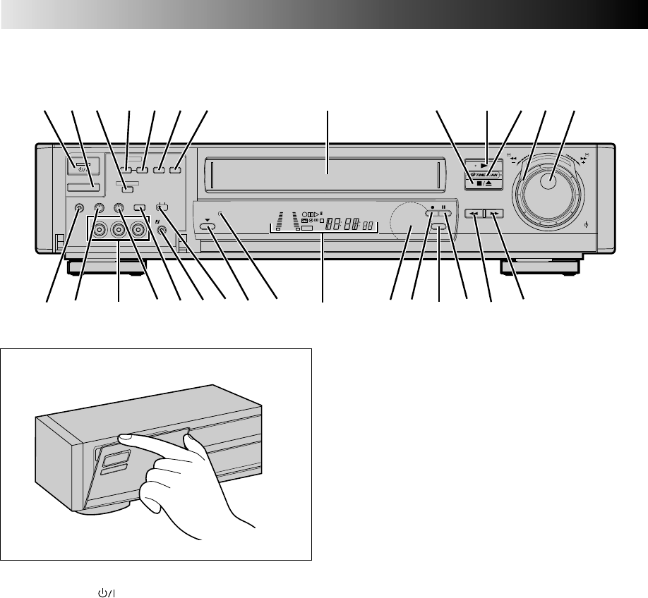
60 EN
INDEX
FRONT VIEW
A.DUB
START INSERT
HEAD PHONE VOLUME Hi-Fi REC
LEVEL
VIDEO
010010
(MONO)L–AUDIO–R
8
S
L
O
W
S
L
O
W
AUTO SP/LP
TIMER
IN/OUT
••
•
•
••
••
••
•
REW FF
TV PROG/
JOG
SHUTTLE
••
•
•
••
••
••
•
PAL MESECAM
AV/S
SELECT
SPATIALIZER
R.A.EDIT
TIMER
SP/LP
JLIP
+8
4
0
6
10
–20dB
NORM
LR
M
VCR
SP
LP
REMAIN
REVIEW
4 5 72 3 6 8 0 @91 #!
^ r w q )
$ etu
y i o
% & * (
Open the lid to access covered connectors and buttons.
1STANDBY/ON Button Z pg. 6
2TIMER Button Z pg. 29, 31
3SPATIALIZER Button Z pg. 18
4R.A. EDIT IN/OUT Button Z pg. 43
5R.A. EDIT START Button Z pg. 43
6A. DUB [Audio Dubbing] Button Z pg. 39
7INSERT Button Z pg. 41
8Cassette Loading Slot
9STOP/EJECT Button Z pg. 14
0PLAY Button Z pg. 14
!TIME SCAN Indicator Z pg. 20
@TIME SCAN SHUTTLE Ring Z pg. 20
#TV PROG Dial Z pg. 23
JOG Dial Z pg. 15
$Headphone Connector*
%Headphone Volume control*
^VIDEO/AUDIO Input Connectors Z pg. 38
&Hi-Fi Audio Recording Level Control (Z pg. 26)
*AV/S SELECT Button Z pg. 35
(J Terminal [JLIP (Joint Level Interface Protocol)
Connector] Z pg. 44
)PAL/MESECAM Switch Z pg. 16
qAUTO SP/LP TIMER Button Z pg. 33
wAUTO SP/LP TIMER Indicator Z pg. 33
eDisplay Panel Z pg. 61
rInfrared Beam Receiving Window
tRECORD Button Z pg. 23
ySP/LP Button Z pg. 23
uPAUSE Button Z pg. 15
iRewind [REW] Button Z pg. 14
oFast Forward [FF] Button Z pg. 14
* It is possible to listen to the audio using headphones.
Adjust the volume level using the Headphone Volume
Control.
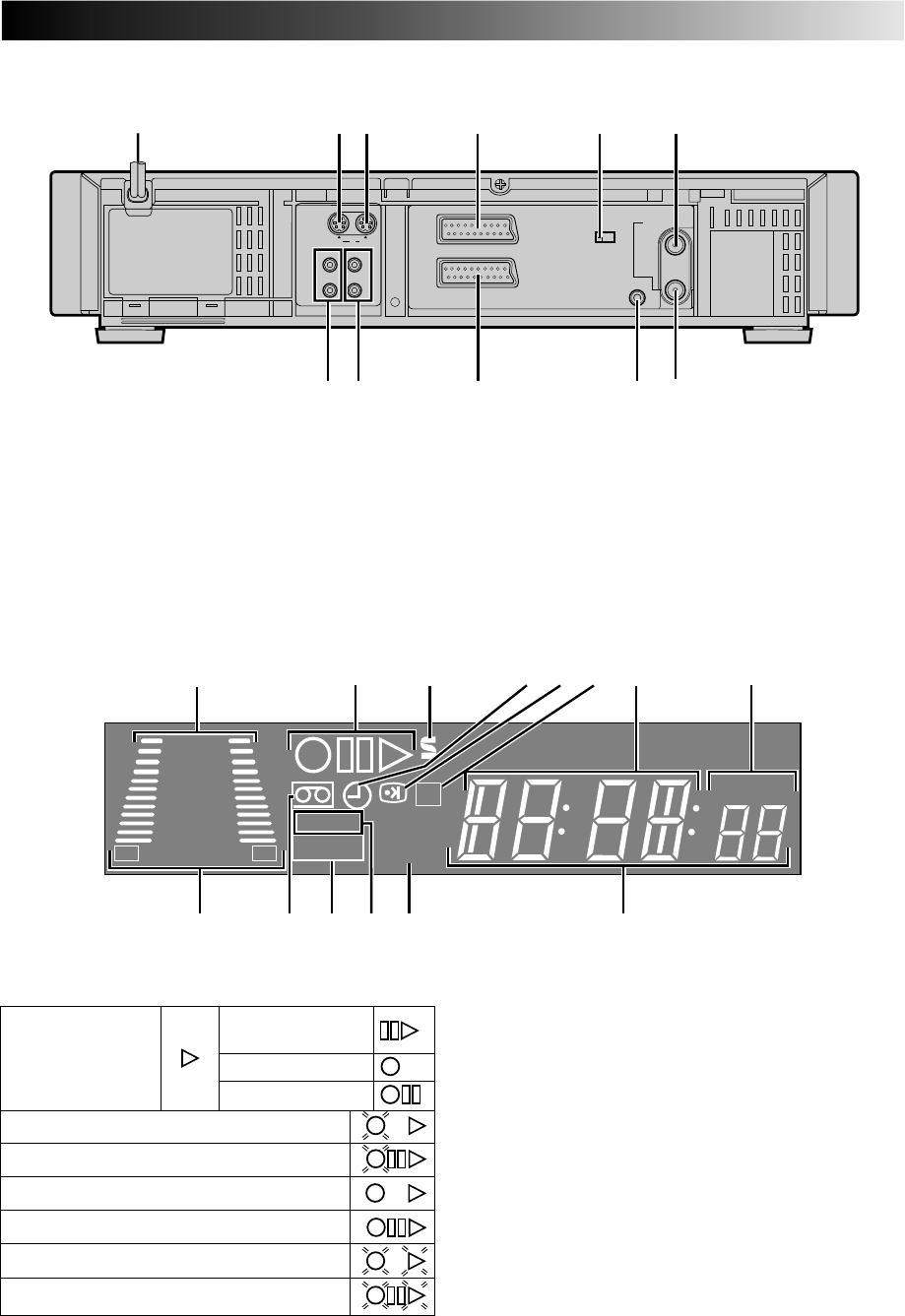
EN 61
REAR VIEW
7AUDIO IN (L/R) Connectors Z pg. 46
8AUDIO OUT (L/R) Connectors Z pg. 46
9AV2 IN/DECODER Connector Z pg. 36, 45
0Remote PAUSE Connector Z pg. 38
R.A.EDIT Connector Z pg. 42
!RF OUT Connector Z pg. 3
1Mains Power Cord Z pg. 3
2S-Video IN Connector Z pg. 36
3S-Video OUT Connector Z pg. 4
4AV1 IN/OUT Connector Z pg. 3, 36
5AV1 OUT Switch Z pg. 3
6ANT. IN Connector Z pg. 3
AV1 IN/OUT
RF OUT
AV2 IN/DECODER
PAUSE/
R.A.EDIT
AV1 OUT
ANT.IN
COMP.
Y/C
RR
LL
AUDIO
S
IN
IN
OUT
OUT
65432
97 0 !
1
8
DISPLAY PANEL
1Audio Level Indicator Z pg. 26
2 Symbolic Mode Indicators
+8
4
0
6
10
–20dB
NORM
LR
M
VCR
SP
LP
REMAIN
REVIEW
45 6
1
9 $
0@#!
73 8
2
3S-VHS Indicator Z pg. 25
4"Timer" Indicator Z pg. 29, 31
5PDC/VPS Indicator Z pg. 33
6Counter Memory Indicator Z pg. 19
7Channel*/Mode Display Z pg. 23
*Channel position 1 will be displayed as "CH 1".
Clock Display Z pg. 7, 55
8Instant REVIEW Indicator Z pg. 17
9Audio Mode Indicator Z pg. 18
0"Cassette Loaded" Mark
!VCR Indicator Z pg. 24
@Tape Speed Indicators Z pg. 23
#Tape Remaining Time Indicator Z pg. 24
$Counter/Remain Display Z pg. 24
STILL:
SLOW:
RECORD:
RECORD PAUSE:
PLAY:
FF/REW VARIABLE
SHUTTLE SEARCH:
AUDIO DUBBING:
AUDIO DUBBING PAUSE:
INSERT:
INSERT PAUSE:
AUDIO DUBBING INSERT:
AUDIO DUBBING INSERT PAUSE:
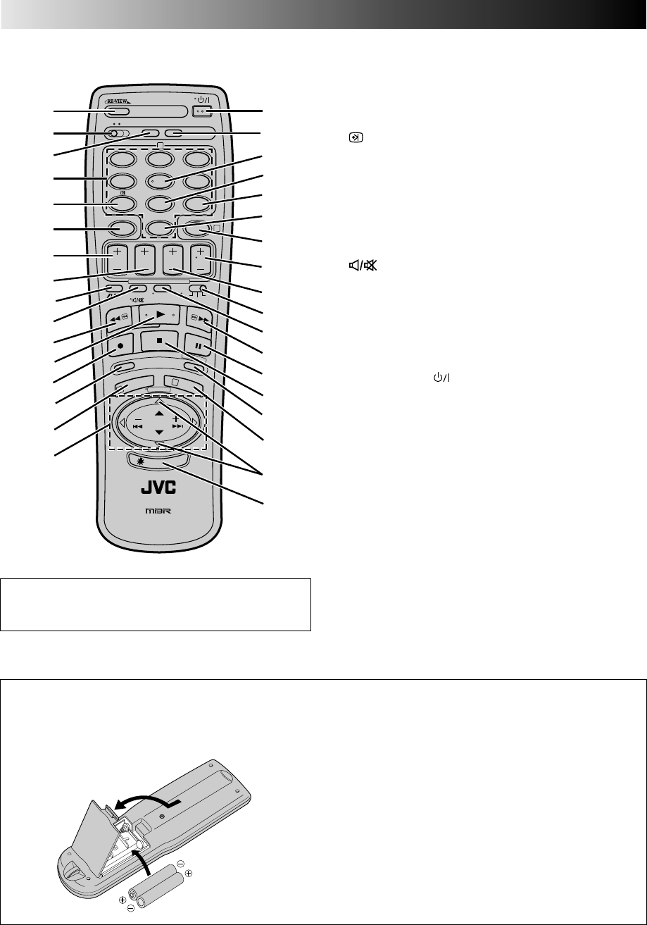
62 EN
REMOTE CONTROL
INDEX (cont.)
Buttons with a small dot on the left side of the name
can also be used to operate your TV with the TV/
SAT/VCR switch set to "TV". Z pg. 48
1REVIEW Button Z pg. 17
2A/B Code Switch Z pg. 19
3C. MEMORY Button Z pg. 19
4NUMBER Keys Z pg. 23, 28
5 (PDC/VPS) Button Z pg. 29, 31
6CANCEL Button Z pg. 13
C. RESET Button Z pg. 24
7START +/– Button Z pg. 30
8STOP +/– Button Z pg. 30
9SP/LP Button Z pg. 23
Auto Tracking Button Z pg. 16
Digit Entry Button Z pg. 48
0AUDIO MONITOR Button Z pg. 18
(TV Mute) Button Z pg. 48
!Rewind [REW] Button Z pg. 14
@Play Button Z pg. 14
#Record Button Z pg. 23
$SCENE FINDER Button Z pg. 19
%PROG/MENU Button Z pg. 9, 28
^PUSH JOG %fi Button Z pg. 9
PUSH JOG Button Z pg. 15, 17, 48
&STANDBY/ON Button Z pg. 6
*DISPLAY Button Z pg. 24
(ADD TIME Button Z pg. 29
)DAILY Button Z pg. 29, 31
qWEEKLY Button Z pg. 29, 31
wAUX Button Z pg. 35
eTIMER Button Z pg. 29, 31
rTV PROG +/– Button Z pg. 23
tDATE +/– Button Z pg. 31
yTV/SAT/VCR Switch Z pg. 48, 49
uTV/VCR Button Z pg. 24, 48
iFast Forward [FF] Button Z pg. 14
oPause Button Z pg. 15
pStop Button Z pg. 14
QPROG CHECK Button Z pg. 32
WOK Button Z pg. 9
ETV VOL %fi Button Z pg. 48
RILLUMI GUIDE Button Z pg. 28
Installing Batteries
1Open the battery compartment cover.
2Insert 2 "R6"-size batteries (provided) in the correct
directions.
3Replace the cover.
How To Use
The remote control can operate most of your video recorder's
functions, as well as basic functions of TV sets and satellite
tuners of JVC and other brands. Z pg. 48, 49.
●Point the remote control toward the sensor window.
●The maximum operating distance of the remote control is
about 8 m.
NOTE:
If the remote control doesn't work properly, remove its
batteries, wait a short time and then try again.
%
%
%
%
S
C
E
N
E
F
I
N
D
E
R
P
R
O
G
C
H
E
C
K
T
V
V
O
L
.
C.MEMORY DISPLAY
DAILY
AUX
ADD TIME
C.RESET
CANCEL
DATESTOP
START
AUDIO MONITOR (MONITOR)
TV/VCR TV SAT VCR
TIMER
WEEKLY
A
12
45
3
6
8
0
79
B
PUSH JOG
MULTI BRAND
REMOTE CONTROL UNIT
TV
PROG
P
R
O
G
/
M
E
N
U
O
K
EXPRESS PROGRAMMING
2
4
1
3
I
L
L
U
M
I
G
U
I
D
E
0
9
#
@
$
u
y
p
Q
4
5
1
6
2
3)
o
i
w
q
(
&
*
e
r
t
7
8
!
W
R
E
%
^

EN 63
SPECIFICATIONS
GENERAL
Power requirement : AC 220 – 240 V`, 50/60 Hz
Power consumption : 27 W (HR-S9400E)
29 W (HR-S9400EH)
Temperature
Operating : 5°C to 40°C
Storage : –20°C to 60°C
Operating position : Horizontal only
Dimensions (WxHxD) : 465 x 105 x 353 mm
Weight : 5.6 kg
Format : S-VHS/VHS PAL standard
Maximum recording time
(SP) : 240 min. with E-240 video
cassette
(LP) : 480 min. with E-240 video
cassette
VIDEO/AUDIO
Signal system : PAL-type colour signal and
CCIR monochrome
signal,625 lines
50 fields
Recording system : DA4 (Double Azimuth) head
helical scan system
Signal-to-noise ratio : 45 dB
Horizontal resolution : 250 lines (VHS)
: 400 lines (S-VHS)
Frequency range : 70 Hz to 10,000 Hz
(Normal audio)
20 Hz to 20,000 Hz
(Hi-Fi audio)
Input/Output : 21-pin scart connectors : IN/
OUT x 1, IN/DECODER x 1
RCA connectors:
VIDEO IN x 1, AUDIO IN x 2,
AUDIO OUT x 1
S-Video connectors:
IN x 1, OUT x 1
TUNER/TIMER
TV channel storage
capacity : 99 positions
(+AUX position "AU")
Tuning system : Frequency synthesized tuner
Channel coverage
(Europe) : VHF 47 – 89/104 – 300/
302 – 470MHz
UHF 470 – 862MHz
(Australia) : CH0 – 5, 5A, CATV
CH6 – 12, CATV
CH28 – 69
(New Zealand) : CH1 – 3, CATV
CH4 – 11, CATV
CH21 – 69
Aerial output : UHF channels 22 – 69
(Adjustable)
Memory backup time : Approx. 60 min.
ACCESSORIES
Provided accessories : RF cable,
Infrared remote control unit,
"R6" battery x 2,
Input cable adapter*,
Output cable adapter*,
S-Video cable, Audio cable
* Provided in Australia and New Zealand only.
Specifications shown are for SP mode unless otherwise
specified.
E.& O.E. Design and specifications subject to change without
notice.
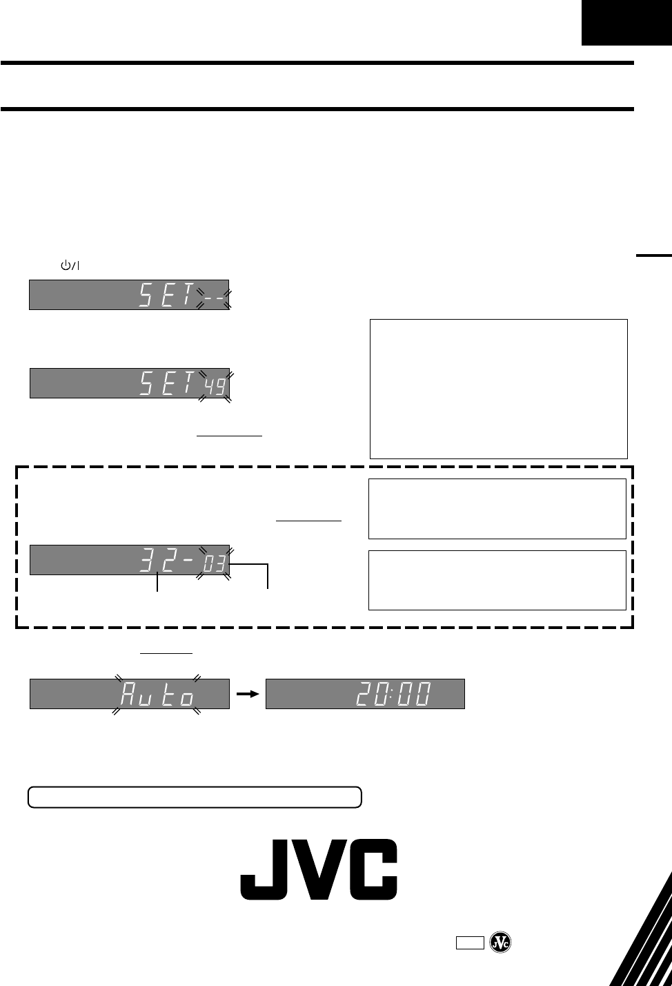
Auto Set Up – referring to the display panel
The Auto Set Up function sets the tuner channels, clock and Guide Program numbers
automatically.
BEFORE YOU START PLEASE MAKE SURE THAT:
nThe TV aerial cable is connected to the ANT.IN jack on the rear panel of the video recorder.
nThe video recorder's mains power cord is connected to a mains outlet.
nThe video recorder is turned off.
nLoad batteries into the remote control.
1
Press (recorder/remote).
2
Press PUSH JOG %fi (remote) to select the international
telephone country code.
●If you have selected a country code other than 32
(BELGIUM) or 41 (SUISSE), go to step 3.
●If you have selected 32 (BELGIUM) or 41 (SUISSE),
press OK (remote) and select the language code by
pressing PUSH JOG %fi (remote), then go to step 3.
Language Code
(Ex.) FRANCAIS is selected for BELGIUM
International Telephone
Country Code
3
Press OK (remote). Do NOT press any button on the video recorder or remote control until the current
time appears.
*
Once you have performed Auto Set Up, even if the recorder's memory backup has expired, the
recorder will not perform Auto Set Up again.
During Auto Set Up Auto Set Up completed
●If "CH1" or "– –:– –"
appears on the display
panel, see page 7 of
the instructions.
FOR MORE INFORMATION SEE INSTRUCTIONS/P6
EN
(Ex.) DEUTSCHLAND is selected.
International Telephone Country Code
SUOMI : 358 SUISSE : 41
PORTUGAL : 351 ITALIA : 39
DEUTSCHLAND : 49 ESPAÑA : 34
NORGE : 47 BELGIUM : 32
SVERIGE : 46 NEDERLAND : 31
DANMARK : 45 GREECE : 30
ÖSTERREICH : 43 OTHERS : - -
* Depending on the model, the selectable codes
may be limited.
Language Code for the HR-S9400E
ENGLISH : 01 ITALIANO : 04
DEUTSCH : 02 NEDERLANDS : 05
FRANCAIS : 03
Language Code for the HR-S9400EH
ENGLISH : 01 CASTELLANO : 04
DEUTSCH : 02 NEDERLANDS : 05
FRANCAIS : 03
HR-S9400E/EH
COPYRIGHT © 1997 VICTOR COMPANY OF JAPAN, LTD. E/EH Printed in Japan
0697HOV
*
UN
*
VP
VICTOR COMPANY OF JAPAN, LIMITED
