Jvc Rx 6020Vbk Users Manual 6020VBK[J]_COVER_f
RX-6020VBK 21063ien
2015-01-23
: Jvc Jvc-Rx-6020Vbk-Users-Manual-325247 jvc-rx-6020vbk-users-manual-325247 jvc pdf
Open the PDF directly: View PDF ![]() .
.
Page Count: 72
- J version
- Top cover
- Warnings, Cautions and Others/ Mises en garde, precautions et indications diverses
- Table of Contents
- Parts Identification
- Getting Started
- Basic Operations
- Basic Settings
- Sound Adjustments
- Tuner Operations
- Creating Realistic Sound Fields
- Using DVD MULTI Playback Mode
- COMPU LINK Remote Control System
- AV COMPU LINK Remote Control System
- Operating JVC’s Audio/Video Components
- Troubleshooting
- Specifications
- Authorized Service Centers
- LIMITED WARRANTY
- Back cover
- C version
- Top cover
- Warnings, Cautions and Others/ Mises en garde, precautions et indications diverses
- Table of Contents
- Parts Identification
- Getting Started
- Basic Operations
- Basic Settings
- English Sound Adjustments
- Tuner Operations
- Creating Realistic Sound Fields
- Using DVD MULTI Playback Mode
- COMPU LINK Remote Control System
- AV COMPU LINK Remote Control System
- Operating JVC’s Audio/Video Components
- Troubleshooting
- Specifications
- Back cover
For Customer Use:
Enter below the Model No. and Serial
No. which are located either on the rear,
bottom or side of the cabinet. Retain this
information for future reference.
Model No.
Serial No.
LVT0851-001A
[J]
INSTRUCTIONS
AUDIO/VIDEO CONTROL RECEIVER
RX-6020VBK
FM MODE
PTY–PTY SEARCH–PTY
DVD VCR TV SOUND
ADJUST
RX-6020V AUDIO/VIDEO CONTROL RECEIVER
SETTING
MASTER VOLUME
CONTROL
DOWN UP
CD TAPE/CDR
SOURCE NAME
INPUT DIGITALINPUT ANALOG
SPEAKERS ON/OFF
SURROUND MODE
PHONES
SURROUND ON/OFF
FM/AM TUNING
STANDBY
FM/AM PRESET FM MODE
MEMORY
INPUT ATT
AM
DIGITAL
SURROUND
STANDBY/ON
DVD MULTI
FM
RX-6020VBK[J]_COVER_f 01.12.7, 11:32 AM1

For Customer Use:
Enter below the Model No. and Serial
No. which are located either on the rear,
bottom or side of the cabinet. Retain this
information for future reference.
Model No.
Serial No.
LVT0851-002A
[C]
RX-6020VBK
FM MODE
PTY–PTY SEARCH–PTY
DVD VCR TV SOUND
ADJUST
RX-6020V AUDIO/VIDEO CONTROL RECEIVER
SETTING
MASTER VOLUME
CONTROL
DOWN UP
CD TAPE/CDR
SOURCE NAME
INPUT DIGITALINPUT ANALOG
SPEAKERS ON/OFF
SURROUND MODE
PHONES
SURROUND ON/OFF
FM/AM TUNING
STANDBY
FM/AM PRESET FM MODE
MEMORY
INPUT ATT
AM
STANDBY/ON
DVD MULTI
FM
INSTRUCTIONS
MANUAL D’INSTRUCTIONS
RECEPTEUR DE CONTROL AUDIO/VIDEO
AUDIO/VIDEO CONTROL RECEIVER
RX-6020VBK[C]_COVER_f 02.1.8, 6:37 PM1
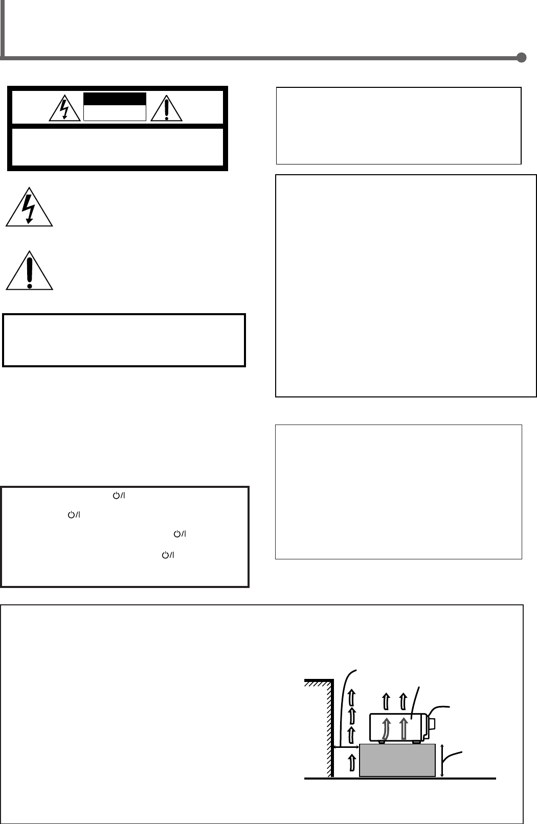
Caution: Proper Ventilation
To avoid risk of electric shock and fire and to protect from damage.
Locate the apparatus as follows:
Front: No obstructions open spacing.
Sides: No obstructions in 10 cm from the sides.
Top: No obstructions in 10 cm from the top.
Back: No obstructions in 15 cm from the back.
Bottom: No obstructions, place on the level surface.
In addition, maintain the best possible air circulation as illustrated.
Attention: Ventilation Correcte
Pour éviter les chocs électriques, l’incendie et tout autre dégât.
Disposer l’appareil en tenant compte des impératifs suivants
Avant: Rien ne doit gêner le dégagement
Flancs: Laisser 10 cm de dégagement latéral
Dessus: Laisser 10 cm de dégagement supérieur
Arrière: Laisser 15 cm de dégagement arrière
Dessous: Rien ne doit obstruer par dessous; poser l’appareil sur une
surface plate.
Veiller également à ce que l’air circule le mieux possible comme illustré.
Floor
Plancher
Stand height
15 cm or more
Hauteur du
socle: 15 cm ou
plus
Front
Avant
Spacing 15 cm or more
Dégagement de 15 cm ou plus
Wall or obstructions
Mur, ou obstruction
Caution –– STANDBY/ON button!
Disconnect the mains plug to shut the power off completely. The
STANDBY/ON button in any position does not disconnect
the mains line. The power can be remote controlled.
Attention –– Commutateur STANDBY/ON !
Déconnecter la fiche de secteur pour couper complètement le
courant. Le commutateur STANDBY/ON ne coupe jamais
complètement la ligne de secteur, quelle que soit sa position. Le
courant peut être télécommandé.
CAUTION
To reduce the risk of electrical shocks, fire, etc.:
1. Do not remove screws, covers or cabinet.
2. Do not expose this appliance to rain or moisture.
ATTENTION
Afin d’éviter tout risque d’électrocution, d’incendie, etc.:
1. Ne pas enlever les vis ni les panneaux et ne pas ouvrir le
coffret de l’appareil.
2. Ne pas exposer l’appareil à la pluie ni à l’humidité.
Warnings, Cautions and Others/
Mises en garde, précautions et indications diverses
RX-6020VBK
WARNING: TO REDUCE THE RISK OF FIRE
OR ELECTRIC SHOCK, DO NOT EXPOSE
THIS APPLIANCE TO RAIN OR MOISTURE.
CAUTION: TO REDUCE THE RISK OF ELECTRIC SHOCK.
DO NOT REMOVE COVER (OR BACK)
NO USER SERVICEABLE PARTS INSIDE.
REFER SERVICING TO QUALIFIED SERVICE PERSONNEL.
RISK OF ELECTRIC SHOCK
DO NOT OPEN
The lightning flash with arrowhead symbol,
within an equilateral triangle is intended to
alert the user to the presence of uninsulated
"dangerous voltage" within the product's
enclosure that may be of sufficient
magnitude to constitute a risk of electric
shock to persons.
The exclamation point within an equilateral
triangle is intended to alert the user to the
presence of important operating and
maintenance (servicing) instructions in the
literature accompanying the appliance.
CAUTION
For Canada/pour Le Canada
THIS DIGITAL APPARATUS DOES NOT EXCEED THE CLASS
B LIMITS FOR RADIO NOISE EMISSIONS FROM DIGITAL
APPARATUS AS SET OUT IN THE INTERFERENCE-CAUSING
EQUIPMENT STANDARD ENTITLED “DIGITAL APPARATUS,”
ICES-003 OF THE DEPARTMENT OF COMMUNICATIONS.
CET APPAREIL NUMERIQUE RESPECTE LES LIMITES DE
BRUITS RADIOELECTRIQUES APPLICABLES AUX
APPAREILS NUMERIQUES DE CLASSE B PRESCRITES
DANS LA NORME SUR LE MATERIEL BROUILLEUR;
“APPAREILS NUMERIQUES”, NMB-003 EDICTEE PAR LE
MINISTRE DES COMMUNICATIONS.
For U.S.A.
This equipment has been tested and found to comply with the limits
for a Class B digital device, pursuant to part 15 of the FCC Rules.
These limits are designed to provide reasonable protection against
harmful interference in a residential installation.
This equipment generates, uses and can radiate radio frequency
energy and, if not installed and used in accordance with the
instructions, may cause harmful interference to radio
communications. However, there is no guarantee that interference
will not occur in a particular installation. If this equipment does cause
harmful interference to radio or television reception, which can be
determined by turning the equipment off and on, the user is
encouraged to try to correct the interference by one or more of the
following measures:
Reorient or relocate the receiving antenna.
Increase the separation between the equipment and receiver.
Connect the equipment into an outlet on a circuit different from that
to which the receiver is connected.
Consult the dealer or an experienced radio/TV technician for help.
Changes or modifications not expressly approved by the
manufacturer for compliance could void the user’s authority to
operate the equipment.
For Canada/pour le Canada
CAUTION: TO PREVENT ELECTRIC SHOCK, MATCH WIDE
BLADE OF PLUG TO WIDE SLOT, FULLY INSERT
ATTENTION: POUR EVITER LES CHOCS ELECTRIQUES,
INTRODUIRE LA LAME LA PLUS LARGE DE LA FICHE DANS LA
BORNE CORRESPONDANTE DE LA PRISE ET POUSSER
JUSQUAU FOND
RX-6020VBK[C]_Safety_f 02.1.8, 9:14 AM1

1
English
Table of Contents
This mark indicates that the remote control CANNOT
be used for the operation explained. Use buttons on
the front panel.
This mark indicates that the remote control CAN
ONLY be used for the operation explained.
Remote
NOT
Remote
ONLY
Parts Identification ...................................... 2
Getting Started........................................... 3
Before Installation ...................................................................... 3
Checking the Supplied Accessories ........................................... 3
Putting Batteries in the Remote Control .................................... 3
Connecting the FM and AM Antennas ....................................... 4
Connecting the Speakers ............................................................ 5
Connecting Audio/Video Components ....................................... 6
Connecting the Power Cord ....................................................... 7
Basic Operations ......................................... 8
Turning On the Power ................................................................ 8
Selecting the Source to Play ....................................................... 8
Adjusting the Volume ................................................................. 9
Listening Only with Headphones ............................................... 9
Turning Off the Sounds Temporarily—Muting........................ 10
Changing the Display Brightness ............................................. 10
Turning Off the Power with the Sleep Timer ........................... 10
Basic Settings ........................................... 11
Setting the Digital Input (DIGITAL IN) Terminals ................. 11
Selecting the Analog or Digital Input Mode ............................ 11
Setting the Speaker Information ............................................... 12
Sound Adjustments.................................... 15
Attenuating the Input Signal .................................................... 15
Adjusting the Front Speakers Output Balance ......................... 15
Adjusting the Tone ................................................................... 15
Adjusting the Subwoofer Output Level.................................... 15
Tuner Operations ....................................... 16
Tuning in Stations .................................................................... 16
Using Preset Tuning ................................................................. 16
Selecting the FM Reception Mode ........................................... 17
Creating Realistic Sound Fields ................... 18
About Relations between Speaker Layout and
Surround Modes ................................................................. 20
Using Dolby Pro Logic II, Dolby Digital and
DTS Digital Surround ........................................................ 21
Using DAP Modes and All Channel Stereo ............................. 23
Using DVD MULTI Playback Mode................ 24
Activating DVD MULTI Playback Mode ................................ 24
COMPU LINK Remote Control System ......... 25
AV COMPU LINK Remote Control System .... 26
Operating JVC's Audio/Video
Components .......................................... 28
Operating Audio Components .................................................. 28
Operating Video Components .................................................. 29
Troubleshooting ......................................... 30
Specifications ............................................ 31
EN01-07.RX-6020V[C]_f 02.1.8, 9:14 AM1
2
English
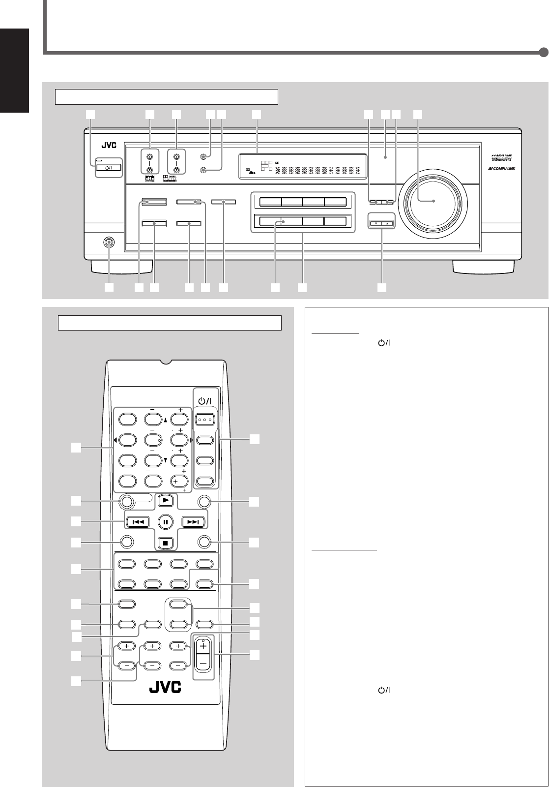
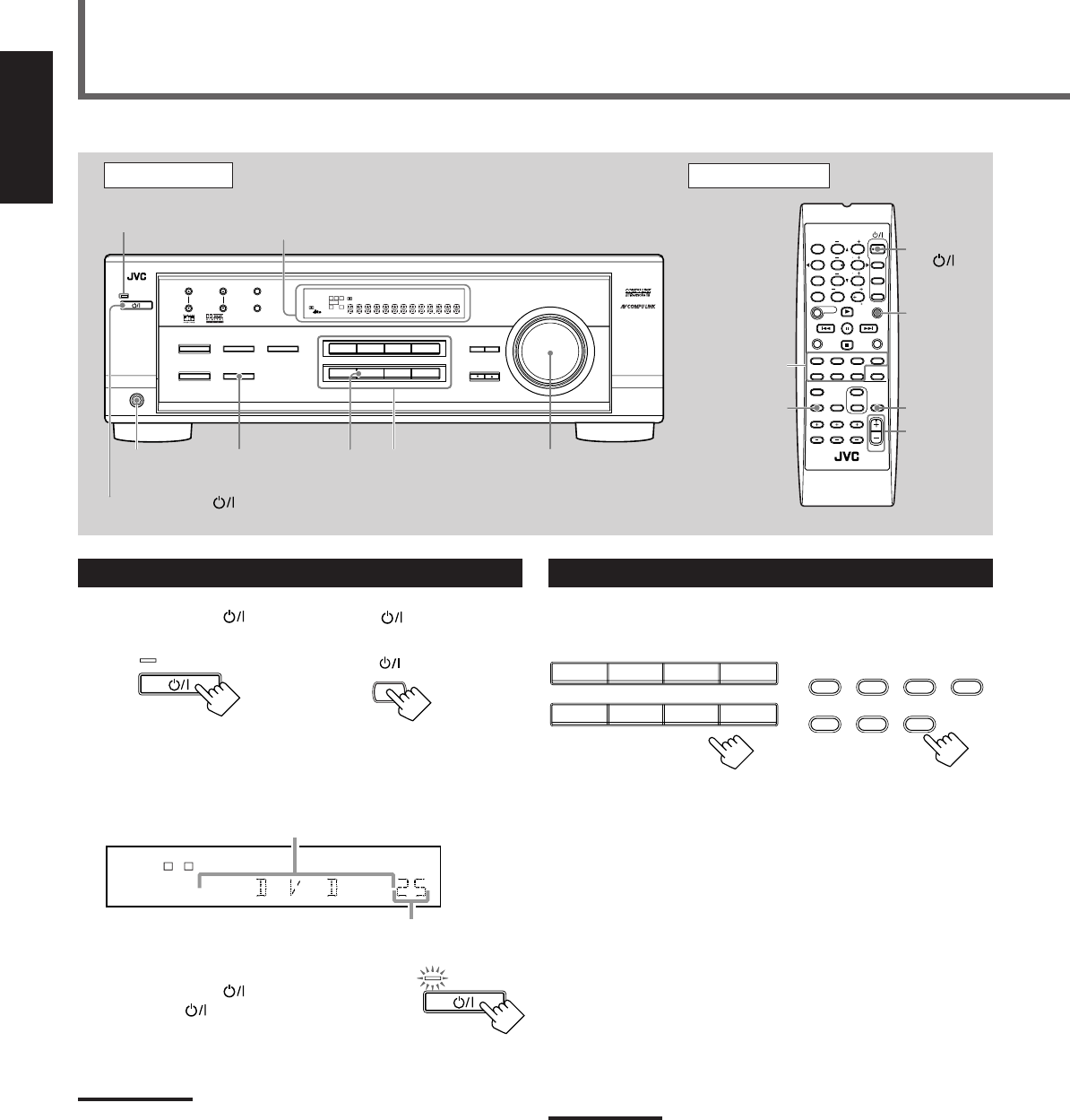
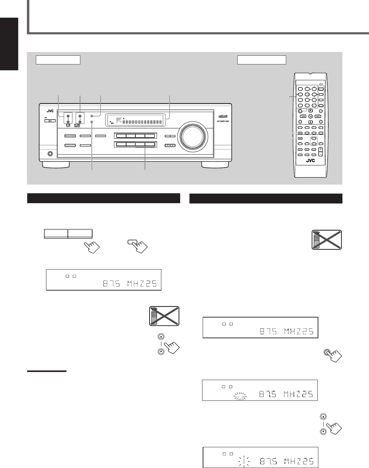
Parts Identification
Front Panel
See page(s) in the parentheses for details.
Remote Control Front Panel
1STANDBY/ON button and STANDBY lamp (8)
2FM/AM TUNING 5/∞ (up/down) buttons (16)
3FM/AM PRESET 5/∞ (up/down) buttons (16, 17)
4FM MODE button (17)
5MEMORY button (16, 17)
6Display (8)
7ADJUST button (15, 22, 23, 24)
8Remote sensor (3)
9SETTING button (11 – 14)
pMASTER VOLUME control (9)
qPHONES jack (9)
wSURROUND ON/OFF button (20 – 23)
eSURROUND MODE button (20 – 23)
rSPEAKERS ON/OFF button (9)
t•INPUT ANALOG button (11)
•INPUT ATT button (15)
yINPUT DIGITAL button (11, 12)
uSOURCE NAME button (9)
iSource selecting buttons (8, 9, 11, 16, 17, 24)
DVD MULTI, DVD, VCR, TV SOUND, CD, TAPE/CDR, FM, AM
oCONTROL UP5/DOWN∞ buttons (11 – 15, 22 – 24)
Remote Control
1• 10 keys for selecting preset channels (17)
•10 keys for adjusting sound (15, 22, 23, 24)
•10 keys for operating audio/video components (28, 29)
2SOUND button (15, 22 – 24)
3Operating buttons for audio/video components
(25, 28, 29)
4REC PAUSE button (28, 29)
5Source selecting buttons (8, 9, 11, 17, 24, 27 – 29)
TAPE/CDR, CD, DVD, DVD MULTI, FM/AM, TV SOUND, VCR
6FM MODE button (17)
7DIMMER button (10)
8TV/VIDEO button (29)
9VCR CH (channel) +/– buttons (29)
pTV CH (channel) +/– buttons (29)
qSTANDBY/ON buttons (8, 26, 29)
AUDIO, TV, VCR, DVD
wSLEEP button (10)
eCD–DISC button (28)
rANALOG/DIGITAL button (12)
tSURROUND ON/OFF and SURROUND MODE buttons
(20, 21, 23, 28)
yMUTING button (10)
uTV VOLUME +/– buttons (29)
iVOLUME +/– button (9)
FM MODE
A/V CONTROL
RECEIVER
AUDIO
TV
VCR
DVD
TEST
EFFECT
MENU
ENTER
RETURN
SOUND
SLEEP
CENTER
REAR L
SUBWOOFER
CD–DISC
REC PAUSE
TAPE/CDR CD DVD DVD MULTI
FM/AM
FM MODE
DIMMER TV/VIDEO
SURROUND
ON/OFF
MODE
MUTING
VCR CH TV CH
VOLUME
TV SOUND VCR ANALOG
/DIGITAL
REAR R
100
1
4
7/P
10
2
5
8
0
3
6
9
10
REMOTE CONTROL RM-SRX6020J
REW FF
TV VOLUME
STANDBY/ON
6
7
3
t
u
y
5
4
9
p
i
r
q
8
2
1
e
w
DVDDVD MULTI VCR TV SOUND
ADJUST
RX-6020V
AUDIO/VIDEO CONTROL RECEIVER
SETTING
MASTER VOLUME
CONTROL
DOWN UP
CD TAPE/CDR
SOURCE NAME
INPUT DIGITALINPUT ANALOG
SPEAKERS ON/OFF
SURROUND MODE
PHONES
SURROUND ON/OFF
FM/AM TUNING
STANDBY
FM/AM PRESET FM MODE
MEMORY
INPUT ATT
FM AM
25
48
7
3
STANDBY/ON
wo
y
t
r
e
q
19p
i
u
6
LC
S.WFR
LS RS
CH-
S
LFE
SPK
PRO LOGIC ΙΙ DSP H.PHONE
AUTO MUTING
TUNED STEREO
VOLUME
INPUT ATT
SLEEP
DIGITAL AUTO
ANALOG
DIGITAL
LINEAR PCM
R
EN01-07.RX-6020V[C]_f 02.1.8, 9:14 AM2
3
English
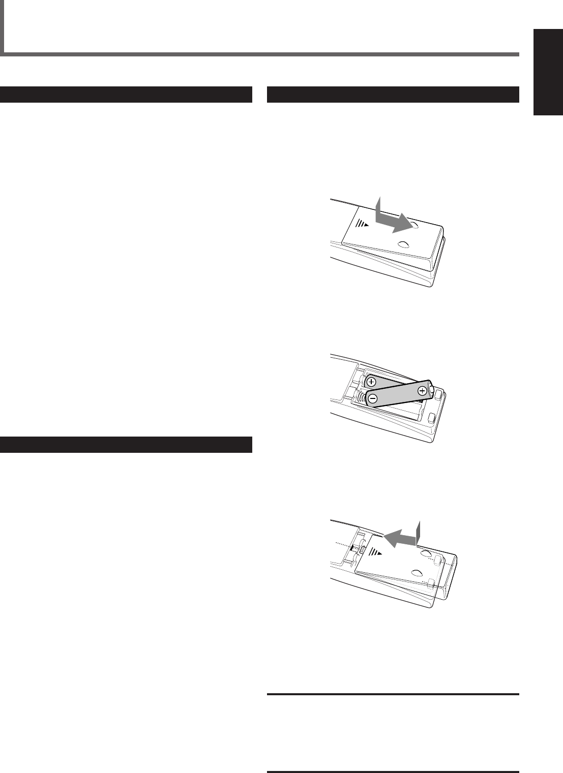
Putting Batteries in the Remote Control
Before using the remote control, put two supplied batteries first.
•When using the remote control, aim the remote control directly at
the remote sensor on the unit.
1
On the back of the remote control, remove the
battery cover.
2
Insert batteries.
•Make sure to match the polarity: (+) to (+) and (–) to (–).
3
Replace the cover.
If the range or effectiveness of the remote control decreases, replace
the batteries. Use two R6P(SUM-3)/AA(15F) type dry-cell batteries.
CAUTION:
Follow these precautions to avoid leaking or cracking cells:
•Place batteries in the remote control so they match the polarity:
(+) to (+) and (–) to (–).
•Use the correct type of batteries. Batteries that look similar may
differ in voltage.
•Always replace both batteries at the same time.
•Do not expose batteries to heat or flame.
Getting Started
Before Installation
General Precautions
•DO NOT insert any metal object to the unit.
•DO NOT disassemble the unit or remove screws, covers, or
cabinet.
•DO NOT expose the unit to rain or moisture.
Locations
•Install the unit in a location that is level and protected from
moisture.
•The temperature around the unit must be between –5˚C and 35˚C
(23˚F and 95˚F).
•Make sure there is good ventilation around the unit. Poor
ventilation could cause overheating and damage the unit.
Handling the unit
•DO NOT touch the power cord with wet hands.
•DO NOT pull the power cord to unplug the cord. When
unplugging the cord, always grasp the plug so as not to damage
the cord.
•Keep the power cord away from the connecting cords and the
antenna. The power cord may cause noise or screen interference. It
is recommended to use a coaxial cable for antenna connection,
since it is well-shielded against interference.
•When a power failure occurs, or when you unplug the power cord,
the preset settings such as preset FM/AM channels and sound
adjustments may be erased in a few days.
Checking the Supplied Accessories
Check to be sure you have all of the following supplied accessories.
The number in the parentheses indicates the quantity of the piece(s)
supplied.
• Remote Control (1)
• Batteries (2)
• AM Loop Antenna (1)
• FM Antenna (1)
If anything is missing, contact your dealer immediately.
EN01-07.RX-6020V[C]_f 02.1.8, 9:14 AM3
4
English
Getting Started
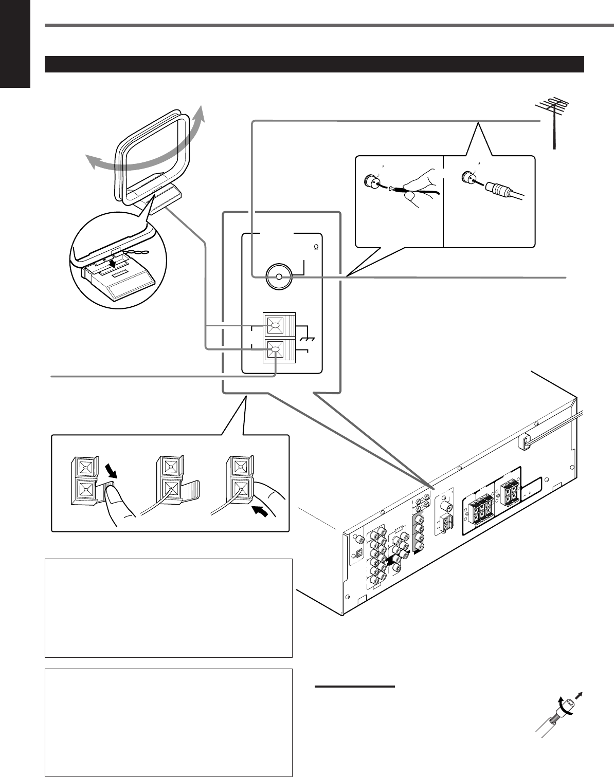
AM loop antenna connection
Connect the AM loop antenna supplied to the AM LOOP
terminals.
Turn the loop until you have the best reception.
•If the reception is poor, connect an outdoor single vinyl-
covered wire (not supplied) to the AM EXT terminal. (Keep
the AM loop antenna connected.)
FM antenna connection
Connect the supplied FM antenna to the FM 75 Ω COAXIAL
terminal as temporary measure.
Extend the supplied FM antenna horizontally.
•If the reception is poor, connect an outdoor FM antenna (not
supplied). Before attaching a 75 Ω coaxial cable (with a
standard type connector), disconnect the supplied FM
antenna.
Connecting the FM and AM Antennas
CENTER
RIGHT
816
DVD
DIGITAL 1
(DVD)
DIGITAL 2 ( CD )
CD
DVD
FM 75
COAXIAL
COMPU LINK-4
(SYNCHRO)
ANTENNA
TV SOUND
AUDIO
VIDEO
AUDIO
OUT
(REC)
RIGHT LEFT
AM
LOOP
AM
EXIT
RIGHT LEFT
TAPE
/CDR
IN
(PLAY)
OUT
(REC) OUT
(REC)
VCR
IN
(PLAY)
VCR
IN
(PLAY)
DIGITAL IN
SUB
WOOFER
CENTER
SPEAKER
REAR
SPEAKERS
RIGHT LEFT
FRONT
SPEAKERS
LEFT
CAUTION :
SPEAKER IMPEDANCE
+
–
+
–
+
–
+
–
AV
COMPU LINK
RIGHT LEFT
REAR
MONITOR
OUT
FRONT
123
AM
LOOP
FM 75
COAXIAL
AM
EXT
ANTENNA
FM 75
COAXIAL
FM 75
COAXIAL
SUBWOOFER
OUT
AM Loop Antenna
(supplied)
or
If AM reception is poor, connect outdoor
single vinyl-covered wire (not supplied).
Extend the supplied FM antenna horizontally.
FM antenna (supplied)
Outdoor FM antenna (not supplied)
If FM reception is poor, connect outdoor FM
antenna.
Supplied FM
antenna
Standard type
outdoor FM antenna
(not supplied)
Snap the tabs on the loop
into the slots of the base
to assemble the AM loop
antenna.
Notes:
•If the AM loop antenna wire is covered with vinyl,
remove the vinyl while twisting it as shown to the right.
•Make sure antenna conductors do not touch any other
terminals, connecting cords and the power cord. This
could cause poor reception.
EN01-07.RX-6020V[C]_f 02.1.8, 9:14 AM4
5
English
SUBWOOFER
OUT
AUDIO
CENTER
FRONT
DVD
SUB
WOOFER
RIGHT LEFT
RIGHT
REAR
LEFT
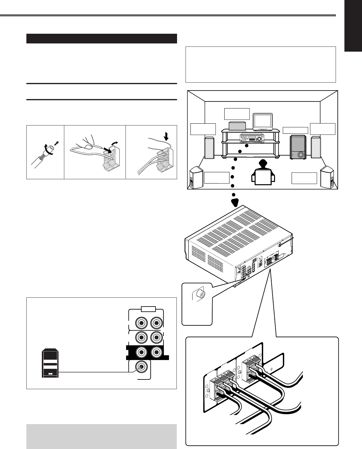
Connecting the Speakers
After connecting the front, center, rear speakers and/or a subwoofer,
set the speaker setting information properly to obtain the best
possible surround effect. For details, see pages 12 to 14.
CAUTION:
Use speakers with the SPEAKER IMPEDANCE indicated by the
speaker terminals.
Connecting the front, center and rear speakers
For each speaker, connect the (+) and (–) terminals on the rear panel
to the (+) and (–) terminals marked on the speakers.
1
Cut, twist and remove the insulation at the end of
each speaker cord.
2
Open the terminal (1), then insert the speaker
cord (2).
3
Close the terminal.
Connecting the subwoofer speaker
By connecting a powered subwoofer, you can enhance the bass or
reproduce the original LFE signals recorded in the digital software.
Connect the input jack of a powered subwoofer to the
SUBWOOFER OUT jack on the rear panel, using a cable with RCA
pin plugs (not supplied).
• Refer also to the manual supplied with your subwoofer.
Since bass sound is non-directional, you can place a powered
subwoofer wherever you like. Normally place it in front of
you.
123
1
2
Powered subwoofer
Speaker layout diagram
“NO” for the subwoofer, “LARGE” for the front speakers,
and “SMALL” for the center and rear speakers are initial
settings. To get best possible sound, change the subwoofer
and speaker settings to fit your listening conditions (See
pages 12 and 13).
Right rear
speaker
DIGITAL 1
(DVD)
DIGITAL 2 ( CD )
CD
FM 75
COAXIAL
ANTENNA
TV SOUND
AUDIO
OUT
(REC)
AM
LOOP
AM
EXIT
RIGHT LEFT
TAPE
/CDR
IN
(PLAY)
OUT
(REC)
VCR
IN
(PLAY)
DIGITAL IN
CENTER
SPEAKER
REAR
SPEAKERS
RIGHT LEFT
FRONT
SPEAKERS
RIGHT LEFT
CAUTION :
SPEAKER IMPEDANCE
816
+
–
+
–
+
–
+
–
CENTER
SPEAKER
REAR
SPEAKERS
RIGHT LEFT
FRONT
SPEAKERS
RIGHT LEFT
CAUTION :
SPEAKER IMPEDANCE
816
+
–
+
–
+
–
+
–
Left front
speaker Subwoofer
Center
speaker
Left rear
speaker
Right front
speaker
To
subwoofer
SUBWOOFER
OUT
DVD
COMPU LINK-4
(SYNCHRO)
VIDEO
OUT
(REC)
VCR
IN
(PLAY)
MONITOR
OUT
DVD
FRONT
SUBWOOFER
OUT
AUDIO
RIGHT LEFT
SUB
WOOFER
RIGHT LEFT
REAR
CENTER
DVD VCR TV SOUND
ADJUST
RX-6020V AUDIO/VIDEO CONTROL RECEIVER
SETTING
MASTER VOLUME
CONTROL
DOWN UP
CD TAPE/CDR
SOURCE NAME
INPUT DIGITALINPUT ANALOG
SPEAKERS ON/OFF
SURROUND MODE
PHONES
SURROUND ON/OFF
FM/AM TUNING
STANDBY
FM/AM PRESET FM MODE
MEMORY
INPUT ATT
AM
DIGITAL
SURROUND
STANDBY/ON
DVD MULTI
FM
To left
front speaker
To left
rear speaker
To right front speaker
To right rear speaker
AV
COMPU LINK
To center speaker
EN01-07.RX-6020V[C]_f 02.1.8, 9:14 AM5
6
English
VIDEO
VCR
OUT
(REC)
IN
(PLAY)
MONITOR
OUT
DVD
IN
(PLAY)
CD
OUT
(REC)
AUDIO
RIGHT LEFT
TV SOUND
OUT
(REC)
VCR
TAPE
CDR
IN
(PLAY)
CD
PHONO
AUDIO
TV SOUND
IN
(PLAY)
CD
IN
(PLAY)
RIGHT LEFT
TAPE
CDR
OUT
(REC)
VCR
OUT
(REC)
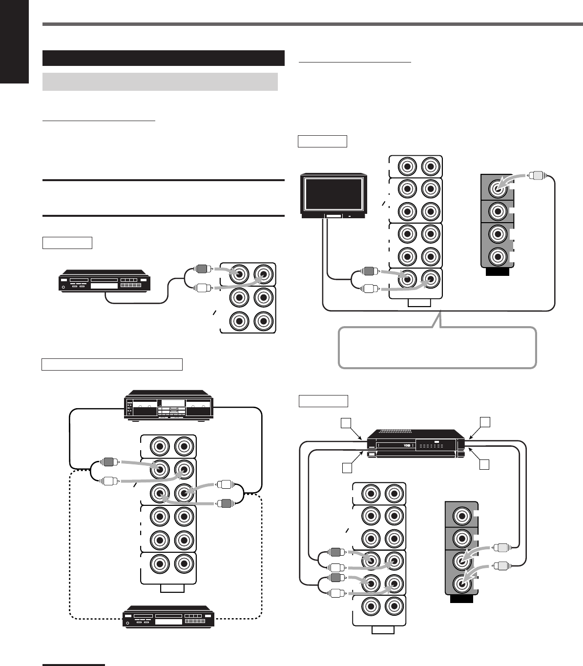
Getting Started
Video component connections
Use the cables with RCA pin plugs (not supplied).
Connect the white plug to the audio left jack, the red plug to the
audio right jack, and the yellow plug to the video jack.
Connecting Audio/Video Components
Turn off all components before connecting.
Analog connections
Audio component connections
Use the cables with RCA pin plugs (not supplied).
Connect the white plug to the audio left jack, and the red plug to the
audio right jack.
CAUTION:
If you connect a sound-enhancing device such as a graphic equalizer
between the source components and this receiver, the sound output
through this receiver may be distorted.
To audio output
CD player
Cassette deck or CD recorder
To audio output
CD recorder
To audio outputTo audio input
TAPE
CDR
CD
OUT
(REC)
IN
(PLAY)
Note:
You can connect either a cassette deck or a CD recorder to the TAPE/
CDR jacks. When connecting a CD recorder to the TAPE/CDR jacks,
change the source name to “CDR”, which will be shown on the display
when selected as the source. See page 9 for details.
If your audio components have a COMPU LINK jack
See also page 25 for detailed information about the connection and
the COMPU LINK remote control system.
TV
To audio
output
Connect the TV to the MONITOR OUT jack to view
the playback picture from the other connected video
components.
To video input
TV
VCR
ÅTo left/right channel audio output
ıTo left/right channel audio input
ÇTo video output
ÎTo video input
VCR
CD player
Cassette deck
To audio input
A
VIDEO
TV SOUND
VCR
OUT
(REC) OUT
(REC)
IN
(PLAY) IN
(PLAY)
TAPE
CDR
CD
OUT
(REC)
IN
(PLAY)
MONITOR
OUT
RIGHT LEFT
DVD
AUDIO
C
D
B
VCR
EN01-07.RX-6020V[C]_f 02.1.8, 9:14 AM6
7
English
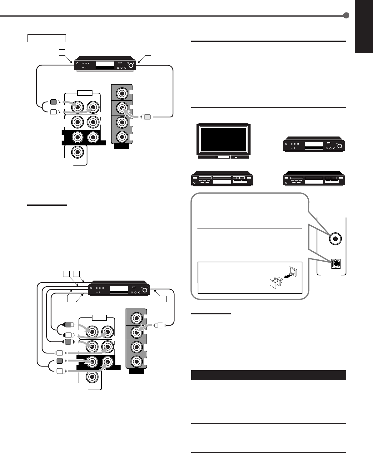
DVD player IMPORTANT:
•When connecting the DVD player or digital TV to the digital terminal,
you also need to connect it to the video jack on the rear. Without
connecting it to the video jack, you cannot view any playback
picture.
•After connecting the components to the DIGITAL IN terminals, make
sure the following if necessary:
–Set the digital input terminal setting correctly. For details, see
“Setting the Digital Input (DIGITAL IN) Terminals” on page 11.
–Select the digital input mode correctly. For details, see “Selecting
the Analog or Digital Input Mode” on page 11.
Notes:
•When shipped from the factory, the DIGITAL IN terminals have
been set for use with the following components:
–DIGITAL 1 (coaxial): For DVD player
–DIGITAL 2 (optical): For CD player
•When you want to operate the CD player or CD recorder using the
COMPU LINK remote control system, connect the target
component also as described in “Analog connections” (see page 6).
Connecting the Power Cord
Before plugging the power cord into an AC outlet, make sure that all
connections have been made.
Plug the power cord into an AC outlet.
CAUTIONS:
•Do not touch the power cord with wet hands.
•Do not pull on the power cord to unplug the cord. When
unplugging the cord, always grasp the plug so as not to damage
the cord.
DVD player
ÅTo front left/right channel audio output (or to audio mixed
output)
ıTo video output
Note:
To enjoy the software encoded with Dolby Digital or DTS Digital
Surround, you must connect the DVD player using the digital terminal
on the rear of this receiver. (See “Digital connections” below.)
SUBWOOFER
OUT
AUDIO
CENTER
FRONT
DVD
SUB
WOOFER
RIGHT LEFT
RIGHT
REAR
LEFT
VIDEO
VCR
OUT
(REC)
IN
(PLAY)
MONITOR
OUT
DVD
DVD
AB
Digital connections
This receiver is equipped with two DIGITAL IN terminals—one
digital coaxial terminal and one digital optical terminal.
You can connect any component to one of the digital terminals using
a digital coaxial cable (not supplied) or digital optical cable (not
supplied).
ÅTo rear left/right channel audio output
ıTo center channel audio output
ÇTo subwoofer audio output
ÎTo front left/right channel audio output
‰To video output
For enjoying DVD MULTI Playback Mode—
•When you connect the DVD player with its analog discrete output
(5.1 CH reproduction) jacks:
DVD player
SUBWOOFER
OUT
AUDIO
CENTER
FRONT
DVD
SUB
WOOFER
RIGHT LEFT
RIGHT
REAR
LEFT
VIDEO
VCR
OUT
(REC)
IN
(PLAY)
MONITOR
OUT
DVD
DVD
BA
E
C
D
DVD
DIGITAL 1
(DVD)
DIGITAL IN
DIGITAL 2 ( CD )
DVD player
Digital TV
CD player CD recorder
When the component has a digital coaxial
output terminal, connect it to the DIGITAL
1 (DVD) terminal, with the digital coaxial
cable (not supplied).
When the component has a digital optical
output terminal, connect it to the DIGITAL
2 (CD) terminal, with the digital optical
cable (not supplied).
Before connecting a digital
optical cable, unplug the
protective plug.
EN01-07.RX-6020V[C]_f 02.1.8, 9:14 AM7
8
English
Turning On the Power
Press STANDBY/ON (or STANDBY/ON AUDIO on the
remote control).
The STANDBY lamp goes off. The name of the current source (or
station frequency) appears on the display.
To turn off the power (into standby mode)
Press STANDBY/ON (or
STANDBY/ON AUDIO on the remote control)
again.
The STANDBY lamp lights up.
NOTE:
A small amount of power is consumed in standby mode. To turn the
power off completely, unplug the AC power cord.
Front Panel Remote Control
MUTING
SLEEP
Source
selecting
buttons
VOLUME
+/–
STANDBY/
ON
AUDIO
Basic Operations
MASTER
VOLUME
DisplaySTANDBY lamp
On the front panel
AUDIO
STANDBY/ON
Source
selecting
buttons
FM MODE
A/V CONTROL
RECEIVER
AUDIO
TV
VCR
DVD
TEST
EFFECT
MENU
ENTER
RETURN
SOUND
SLEEP
CENTER
REAR L
SUBWOOFER
CD–DISC
REC PAUSE
TAPE/CDR CD DVD DVD MULTI
FM/AM
FM MODE
DIMMER TV/VIDEO
SURROUND
ON/OFF
MODE
MUTING
VCR CH TV CH
VOLUME
TV SOUND VCR ANALOG
/DIGITAL
REAR R
100
1
4
7/P
10
2
5
8
0
3
6
9
10
REMOTE CONTROL RM-SRX6020J
REW FF
TV VOLUME
STANDBY/ON
STANDBY/ON
SPEAKERS
ON/OFF
PHONES
jack SOURCE
NAME
LC
S.WFR
LS RS
CH-
S
LFE
SPK
VOLUME
ANALOG
R
Current volume level is shown here
Current source name appears
STANDBY
STANDBY/ON
DVDDVD MULTI VCR TV SOUND
CD TAPE/CDR
SOURCE NAME
FM AM
TAPE/CDR CD DVD DVD MULTI
FM/AM TV SOUND VCR
Selecting the Source to Play
Press one of the source selecting buttons.
The selected source name appears on the display.
On the front panel From the remote control
DVD MULTI : Select the DVD player for viewing the digital video
disc using the analog discrete output mode (5.1 ch
reproduction).
To enjoy the DVD MULTI playback, see page 24.
DVD : Select the DVD player.
VCR : Select the VCR.
TV SOUND : Select the TV sound.
CD * : Select the CD player.
TAPE/CDR * : Select the cassette deck (or the CD recorder).
FM and AM (FM/AM) *
: Select an FM or AM broadcast.
•Each time you press FM/AM on the remote
control, the band alternates between FM and AM.
Notes:
•When connecting a CD recorder (to the TAPE/CDR jacks), change
the source name that appears on the display. See page 9 for
details.
•When you have connected some digital source components using
digital terminals (see page 7), you need to select the digital input
mode (see page 11).
•When you press one of the source selecting buttons on the remote
control marked above with an asterisk (
*
), the receiver
automatically turns on.
From the remote control
DIMMER
STANDBY/ON
STANDBY
DVDDVD MULTI VCR TV SOUND
ADJUST
RX-6020V
AUDIO/VIDEO CONTROL RECEIVER
SETTING
MASTER VOLUME
CONTROL
DOWN UP
CD TAPE/CDR
SOURCE NAME
INPUT DIGITALINPUT ANALOG
SPEAKERS ON/OFF
SURROUND MODE
PHONES
SURROUND ON/OFF
FM/AM TUNING
STANDBY
FM/AM PRESET FM MODE
MEMORY
INPUT ATT
FM AM
STANDBY/ON
LC
S.WFR
LS RS
CH-
S
LFE
SPK
PRO LOGIC ΙΙ DSP H.PHONE
AUTO MUTING
TUNED STEREO
VOLUME
INPUT ATT
SLEEP
DIGITAL AUTO
ANALOG
DIGITAL
LINEAR PCM
R
EN08-17.RX-6020V[C]_f 02.1.8, 9:14 AM8
9
English
Changing the source name
When you connect the CD recorder to the
TAPE/CDR jacks on the rear panel, change the
source name shown on the display.
1
Press TAPE/CDR (SOURCE NAME).
•Make sure “TAPE” appears on the display.
2
Press and hold SOURCE NAME (TAPE/CDR)
until “ASSIGN CDR” appears on the display.
To change the source name from “CDR” to “TAPE,” repeat the
same procedure above (in step
1
, make sure “CDR” appears on the
display).
Note:
Without changing the source name, you can still use the connected
component. However, there may be some inconvenience:
–“TAPE” will appear on the display when you select the CD
recorder.
–You cannot use the digital input (see page 11) for the CD recorder.
–You cannot use the COMPU LINK remote control system (see page
25) to operate the CD recorder.
Selecting different sources for each picture and
sound
You can watch picture from a video component while listening to
sound from another component.
Press one of the audio source selecting buttons—CD, TAPE/CDR,
FM, AM (FM/AM), while viewing the picture from a video
component such as the VCR or DVD player, etc.
On the front panel From the remote control
Note:
Once you have selected a video source, pictures of the selected
source are sent to the TV until you select another video source.
SOURCE NAME
TAPE/CDR
Remote
NOT
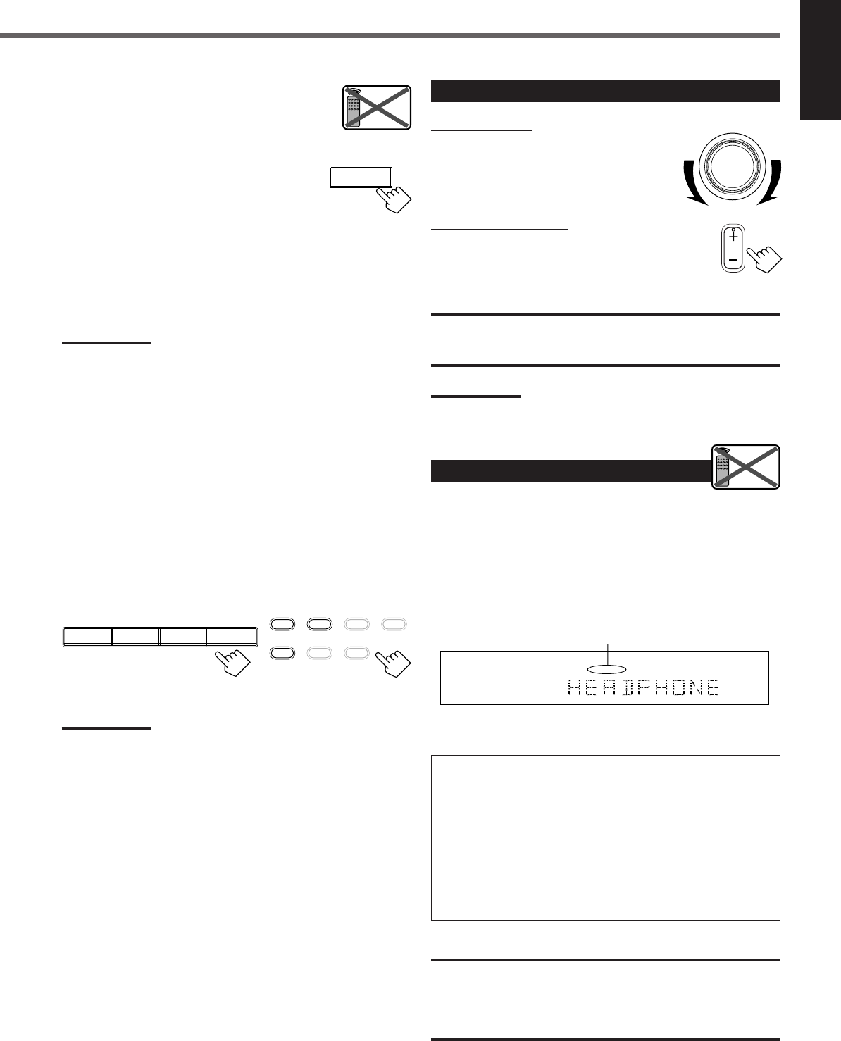
Adjusting the Volume
On the front panel:
To increase the volume, turn MASTER
VOLUME clockwise.
To decrease the volume, turn it
counterclockwise.
From the remote control:
To increase the volume, press VOLUME +.
To decrease the volume, press VOLUME –.
CAUTION:
Always set the volume to the minimum before starting any source. If
the volume is set at its high level, the sudden blast of sound energy
can permanently damage your hearing and/or ruin your speakers.
Note:
The volume level can be adjusted within the range from “0” (minimum)
to “50” (maximum).
Listening Only with Headphones
You must turn off speakers when you listen with headphones.
1
Connect a pair of headphones to the PHONES jack on the front
panel.
2
Press SPEAKERS ON/OFF.
•“HEADPHONE” appears for a while and the H. PHONE
indicator lights up on the display.
This cancels the Surround mode currently selected, and activates
the HEADPHONE mode (see below).
HEADPHONE mode:
When using the headphones, following signals are output
regardless of your speaker setting:
— For 2 channel sources, the front left and right channel signals
are output directly from the headphones.
— For multichannel sources, the front left, right, center, and rear
channel signals are down-mixed and then output from the
headphones.
You can enjoy multichannel sound sources using the
headphones.
CAUTION:
Be sure to turn down the volume:
•Before connecting or putting on headphones, as high volume can
damage both headphones and your hearing.
•Before turning on speakers again, as high volume may output from
the speakers.
MASTER VOLUME
VOLUME
Remote
NOT
L
H.PHONE
ANALOG
R
The H. PHONE indicator lights up.
CD TAPE/CDR
SOURCE NAME
FM AM
TAPE/CDR CD DVD DVD MULTI
FM/AM TV SOUND VCR
EN08-17.RX-6020V[C]_f 02.1.8, 9:14 AM9
10
English
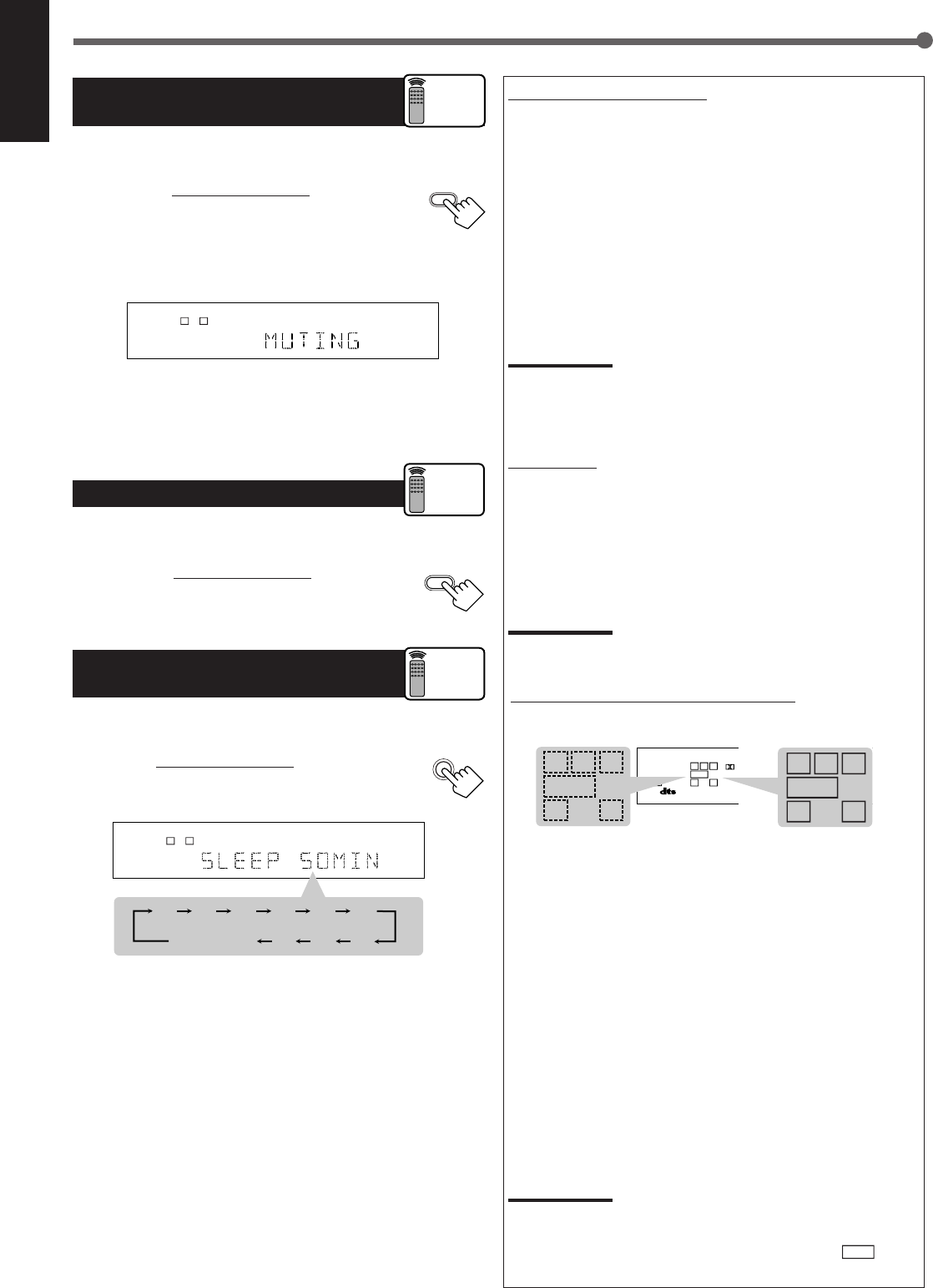
Turning Off the Sounds
Temporarily—Muting
You can mute the sound temporarily.
Press MUTING on the remote control to mute
the sound through all speakers or headphones
connected.
•“MUTING” appears on the display and the volume
turns off (the volume level indicator goes off).
To restore the sound, press MUTING again.
•Turning MASTER VOLUME on the front panel or pressing
VOLUME +/– on the remote control also restores the sound.
Changing the Display Brightness
You can dim the display.
Press DIMMER on the remote control.
•Each time you press the button, the display dims and
brightens alternately.
Turning Off the Power
with the Sleep Timer
You can fall asleep while listening to music—Sleep Timer.
Press SLEEP on the remote control repeatedly.
•The SLEEP indicator lights up on the display, and the
shut-off time changes in 10 minutes intervals.
When the shut-off time comes
The receiver turns off automatically.
To check or change the time remaining before the shut-off time
Press SLEEP once.
The remaining time (in minutes) until the shut-off time appears.
•To change the shut-off time, press SLEEP repeatedly until
preferred remaining time appears on the display.
To cancel the Sleep Timer
Press SLEEP repeatedly until “SLEEP 0 MIN” appears on the
display. (The SLEEP indicator goes off.)
•Turning off the power also cancels the Sleep Timer.
Basic Operations
LC
S.WFR
LS RS
CH-
S
LFE
SPK
ANALOG
R
MUTING
DIMMER
Remote
ONLY
SLEEP
2010 30 40 50 60
70
8090
(Canceled)
0
LC
S.WFR
LS RS
CH-
S
LFE
SPK SLEEP
ANALOG
R
Remote
ONLY
Basic adjustment auto memory
This receiver memorizes sound settings for each source when:
•Turning off the power,
•Changing the source, and
•Assigning the source name.
When you change the source, the memorized settings for the newly
selected source are automatically recalled.
Following can be stored for each source:
•Input attenuator mode (see page 15)
•Balance (see page 15)
•Tone adjustment (see page 15)
•Subwoofer output level (see page 15)
•Surround mode selection (see pages 21–23)
Notes:
•You cannot assign and store different settings for digital input mode
and analog input mode.
•If the source is FM or AM, you can assign a different setting for
each band.
For recording
You can record any source playing through the receiver to a cassette
deck (or a CD recorder) connected to the TAPE/CDR jacks and the
VCR connected to the VCR jacks at the same time.
While recording, you can listen to the selected sound source at
whatever sound level you like without affecting the sound levels of
the recording.
Note:
The output level, tone adjustment (see page 15), and Surround
modes (see pages 21–23) cannot affect the recording.
Signal and speaker indicators on the display
Signal indicators Speaker indicators
The following signal indicators light up—:
L:•When digital input is selected: Lights up when the left
channel signal comes in.
•When analog input is selected: Always lights up.
R:•When digital input is selected: Lights up when the right
channel signal comes in.
•When analog input is selected: Always lights up.
C:When the center channel signal comes in.
LS : When the left rear channel signal comes in.
RS : When the right rear channel signal comes in.
S:When the monaural rear channel signal or 2 ch Dolby
Surround encoded signal comes in.
LFE: When the LFE channel signal comes in.
The speaker indicators light up when both of the following
conditions are satisfied:
•The corresponding speaker is activated, and
•The corresponding speaker is required for the current playback.
Notes:
•When you select “DVD MULTI,” all signal indicators except “S” light
up.
•When “SUBWOOFER” is set to “YES” (see page 12),
S.WFR
lights
up.
Remote
ONLY
LC
S.WFR
LS RS
CH-
S
LFE
SPK ONE TOUCH
PRO LOGIC ΙΙ
DIGITAL AUTO
ANALOG
DIGITAL
LINEAR PCM
R
S.WFR
LS RSS
LFE
RCL
S.WFR
LS RSS
LFE
RCL
EN08-17.RX-6020V[C]_f 02.1.8, 9:14 AM10
11
English
Selecting the Analog or Digital Input
Mode
When you have connected digital source components using both the
analog connections (see page 6) and the digital connections (see
page 7) methods, you need to select the input mode correctly.
1
Press one of the source selecting buttons—DVD,
TV SOUND, CD, or TAPE/CDR*—for which you
want to change the input mode.
Note:
*
Among the sources listed above, you can select the digital input
only for the sources which you have selected the digital input
terminals for. (See “Setting the Digital Input (DIGITAL IN)
Terminals” on the left column.)
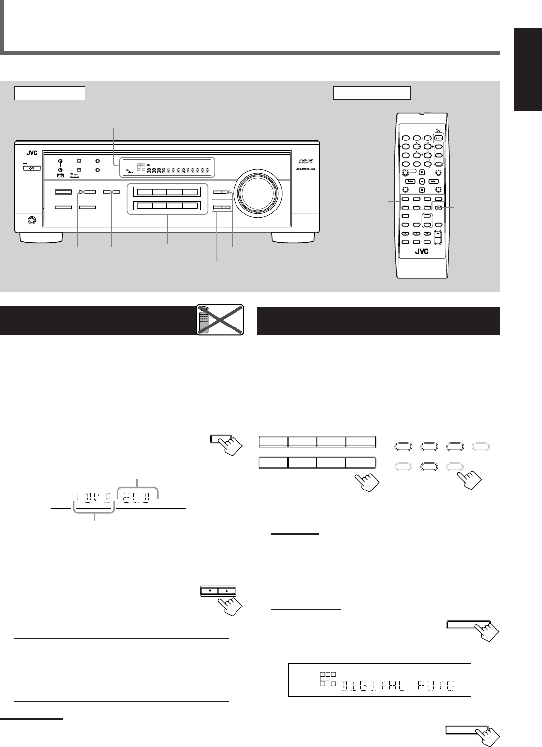
2
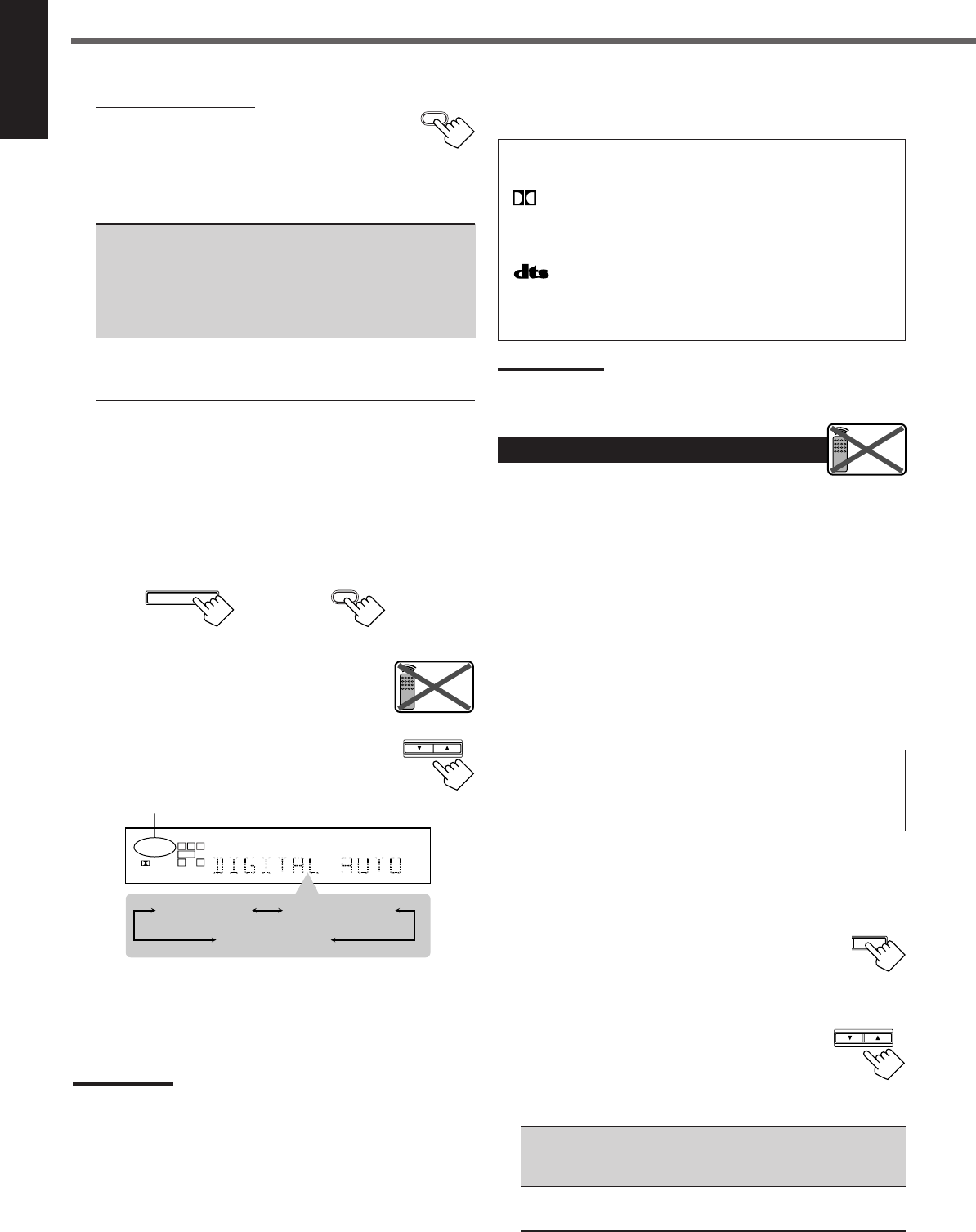
Select digital input mode.
On the front panel:
Press INPUT DIGITAL.
“DIGITAL AUTO” appears on the display and
the indicator for the detected signals also lights
up.
Ex: With the incoming signals of Linear PCM
To change the input mode back to analog
input, press INPUT ANALOG.
“ANALOG” appears on the display and the
analog indicator also lights up.
Setting the Digital Input
[DIGITAL IN] Terminals
When you use the digital input terminals, register what components
are connected to which terminals (DIGITAL 1/2) so that the correct
source name will appear when you select the digital source.
Before you start, remember...
There is a time limit in doing the following steps. If the setting is
canceled before you finish, start from step
1
again.
1
Press SETTING repeatedly until
“DIGITAL IN” appears on the display.
Then the display changes to show the current setting.
* “1DVD 2CD” is the initial setting. If you have already
changed the setting, another combination will be shown.
2
Press CONTROL UP 5/DOWN ∞ to
select the appropriate digital terminal
setting.
•Each time you press the button, the display
changes as follows:
1 DVD 2 CD j1 DVD 2 TV j1 DVD 2 CDR j
1 CD 2 DVD j1 CD 2 TV j1 CD 2 CDR j
1 TV 2 DVD j1 TV 2 CD j1 TV 2 CDR j
1 CDR 2 DVD j1 CDR 2 CD j1 CDR 2 TV j
(back to the beginning)
Note:
When shipped from the factory, the DIGITAL IN terminals can be used
as the digital input for the following components:
–DIGITAL 1 (coaxial): For DVD player
–DIGITAL 2 (optical): For CD player
Basic Settings
Front Panel Remote Control
Display
Source
selecting
buttons
CONTROL
UP 5/DOWN ∞
ANALOG/
DIGITAL
SETTING
Remote
NOT
INPUT
DIGITAL
Source
selecting
buttons
SETTING
INPUT
ANALOG
FM MODE
A/V CONTROL
RECEIVER
AUDIO
TV
VCR
DVD
TEST
EFFECT
MENU
ENTER
RETURN
SOUND
SLEEP
CENTER
REAR L
SUBWOOFER
CD–DISC
REC PAUSE
TAPE/CDR CD DVD DVD MULTI
FM/AM
FM MODE
DIMMER TV/VIDEO
SURROUND
ON/OFF
MODE
MUTING
VCR CH TV CH
VOLUME
TV SOUND VCR ANALOG
/DIGITAL
REAR R
100
1
4
7/P
10
2
5
8
0
3
6
9
10
REMOTE CONTROL RM-SRX6020J
REW FF
TV VOLUME
STANDBY/ON
CONTROL
DOWN UP
S.WFR
LS RS
CH-
S
LFE
DIGITAL 2 terminal setting
DIGITAL 1 terminal setting
TO BE CONTINUED ON THE NEXT PAGE
DVDDVD MULTI VCR TV SOUND
CD TAPE/CDR
SOURCE NAME
FM AM
TAPE/CDR CD DVD DVD MULTI
FM/AM TV SOUND VCR
On the front panel From the remote control
L
S.WFR
CH-
S
SPK
DIGITAL AUTO
LINEAR PCM
R
INPUT DIGITAL
INPUT ANALOG
INPUT ATT
DVDDVD MULTI VCR TV SOUND
ADJUST
RX-6020V
AUDIO/VIDEO CONTROL RECEIVER
SETTING
MASTER VOLUME
CONTROL
DOWN UP
CD TAPE/CDR
SOURCE NAME
INPUT DIGITALINPUT ANALOG
SPEAKERS ON/OFF
SURROUND MODE
PHONES
SURROUND ON/OFF
FM/AM TUNING
STANDBY
FM/AM PRESET FM MODE
MEMORY
INPUT ATT
FM AM
STANDBY/ON
LC
LS RS
CH-
S
SPK
PRO LOGIC ΙΙ DSP H.PHONE
AUTO MUTING
TUNED STEREO
VOLUME
INPUT ATT
SLEEP
DIGITAL AUTO
ANALOG
DIGITAL
LINEAR PCM
R
S.WFR
EN08-17.RX-6020V[C]_f 02.1.8, 9:15 AM11
12
English
The following are the analog/digital signal indicators on the display to
indicate what type of the signal comes into the receiver.
ANALOG : Lights when the analog input is selected.
LINEAR PCM : Lights when Linear PCM signals come in.
DIGITAL :•Lights when Dolby Digital signals come in.
•Flashes when “DOLBY DIGITAL” is
selected for software not encoded with Dolby
Digital signals.
:•Lights when DTS signals come in.
•Flashes when “DTS SURROUND” is
selected for software not encoded with DTS
signals.
Note:
When “DIGITAL AUTO” cannot recognize the incoming signals, no
digital signal indicator lights up on the display.
Setting the Speaker Information
To obtain the best possible sound or effect from Surround modes
(see pages 21–23), register the following speakers and subwoofer
information after all connections are completed.
The following are items you can set:
•Subwoofer information—SUBWOOFER
•Speaker size—FRNT SP, CNTR SP, REAR SP
•Speaker distance—UNIT, FRNT DIS, CNTR DIS, REAR DIS
•Crossover frequency—CROSS
•Low frequency effect attenuator—LFE ATT
•Dynamic range compression—D. COMP
Before you start, remember...
There is a time limit in doing the following steps. If the setting is
canceled before you finish, start from step
1
again.
“NO” for the subwoofer, “LARGE” for the front speakers,
and “SMALL” for the center and rear speakers are initial
settings. To get best possible sound, change the subwoofer and
speaker settings to fit your listening conditions.
Subwoofer information
Register whether you have connected a subwoofer or not.
1
Press SETTING repeatedly until
“SUBWOOFER” (with the current
setting) appears on the display.
2
Press CONTROL UP 5/DOWN ∞
to register whether you have
connected a subwoofer or not.
•Each time you press the button, the
subwoofer setting alternates between “YES” and “NO.”
YES : Select this when you have connected a subwoofer.
You can adjust the subwoofer output level
(see page 15).
NO : Select this when you have not connected or have
disconnected a subwoofer.
From the remote control:
Press ANALOG/DIGITAL.
The current setting indication appears on the display.
•Each time you press the button, the input mode alternates
between the analog input (“ANALOG”) and the digital input
(“DIGITAL AUTO”).
DIGITAL AUTO : Select this for the digital input mode. The
receiver automatically detects the
incoming signal format. (The DIGITAL
AUTO indicator lights up on the display,
then the digital signal indicator for the
detected signals lights up.)
ANALOG : Select this for the analog input mode.
(Initial setting when shipped from the
factory.)
If the following symptoms occur while playing Dolby Digital or
DTS Digital Surround software with “DIGITAL AUTO”
selected, follow the procedure below:
–Sound does not come out at the beginning of playback.
–Noise comes out while searching or skipping chapters or tracks.
1
Press INPUT DIGITAL (or ANALOG/DIGITAL on the remote
control).
“DIGITAL AUTO” appears on the display.
On the front panel From the remote control
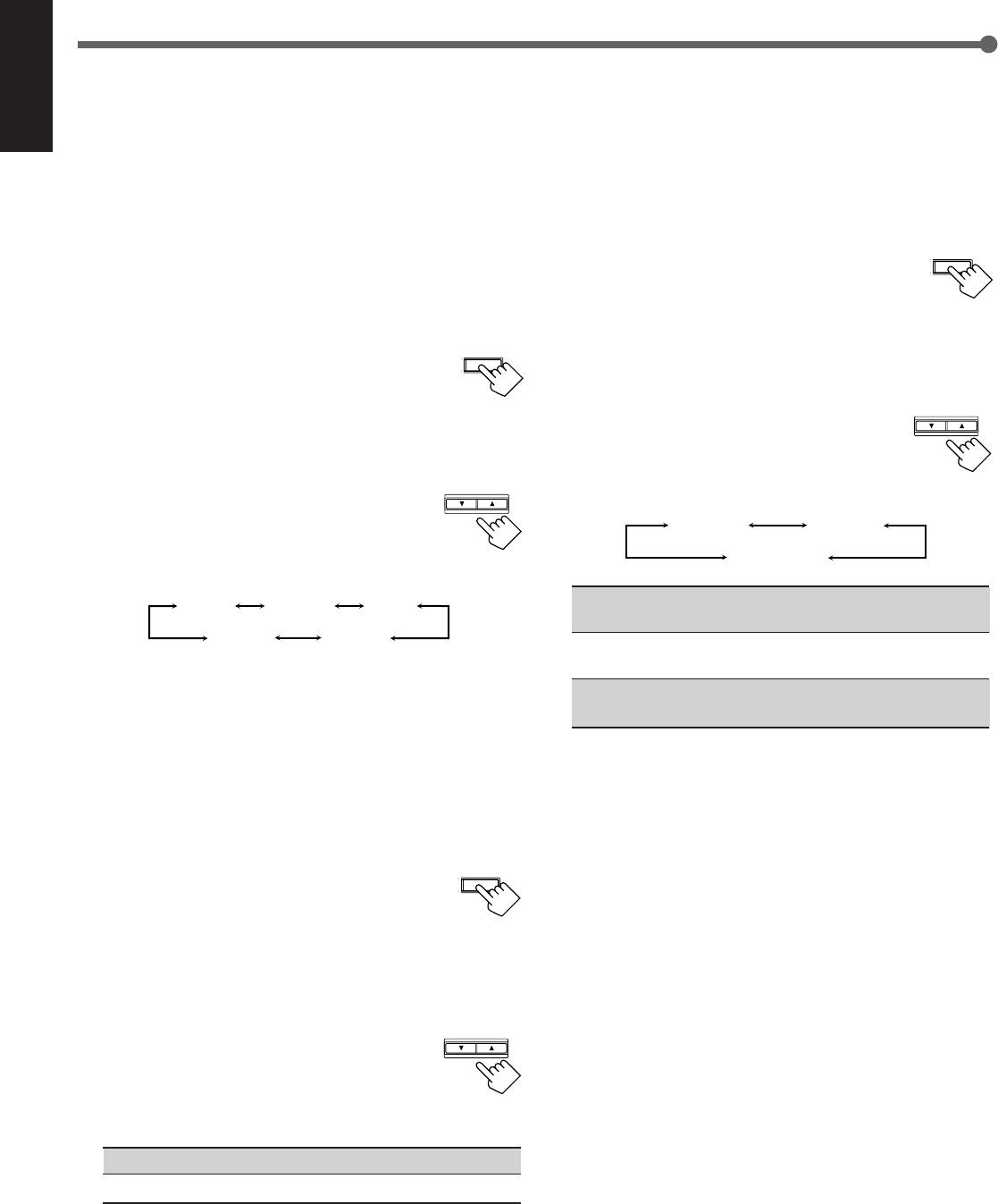
2
Press CONTROL UP 5/DOWN ∞ to select
“DOLBY DIGITAL” or “DTS SURROUND”
while “DIGITAL AUTO” still remains on the
display.
•Each time you press the button, the digital input
mode changes as follows:
When “DOLBY DIGITAL” or “DTS
SURROUND” is selected, “DIGITAL AUTO” goes off.
•To play back software encoded with Dolby Digital, select
“DOLBY DIGITAL.”
•To play back software encoded with DTS Digital Surround,
select “DTS SURROUND.”
Note:
When you turn off the power or select another source, “DOLBY
DIGITAL” and “DTS SURROUND” are canceled and the digital input
mode is automatically reset to “DIGITAL AUTO.”
Basic Settings
ANALOG
/DIGITAL
ANALOG
/DIGITAL
INPUT DIGITAL
Remote
NOT
CONTROL
DOWN UP
LC
S.WFR
LS RS
CH-
S
LFE
SPK
DIGITAL AUTO
DIGITAL
R
DIGITAL AUTO DTS SURROUND
DOLBY DIGITAL
T SETTING
Remote
NOT
CONTROL
DOWN UP
EN08-17.RX-6020V[C]_f 02.1.8, 9:15 AM12
13
English
Speaker distance
Register the unit you use, then the speaker distance from your
listening point.
•If you have set the unit before, start from step
3
.
•Speaker distance is not valid for the DVD MULTI playback mode.
1
Press SETTING repeatedly until
“UNIT” (with the current setting)*
appears on the display.
*“METER” is the initial setting. If you have already changed the
setting, “FEET” will be shown.
2
Press CONTROL UP 5/DOWN ∞ to
select the unit.
•Each time you press the button, the setting
alternates between “METER” and “FEET.”
METER : Speaker distance is shown in meter.
FEET : Speaker distance is shown in feet.
3
Press SETTING repeatedly until
“FRNT DIS (Front distance),” “CNTR
DIS (Center distance),” or “REAR DIS
(Rear distance)” (with the current setting)*
appears on the display.
•The display shows the current setting in the unit selected in
step
2
.
*“3.0m” is the initial setting for meter and “10FT” is for feet. If
you have already changed the setting, another value will be
shown.
4
Press CONTROL UP 5/DOWN ∞
to select the appropriate speaker
distance.
•If you have selected “METER” in step
2
, the
value is changed from “0.3m” to “9.0m” by 0.3 m step.
•If you have selected “FEET” in step
2
,
the value is changed
from “1FT” to “30FT” by 1 foot step.
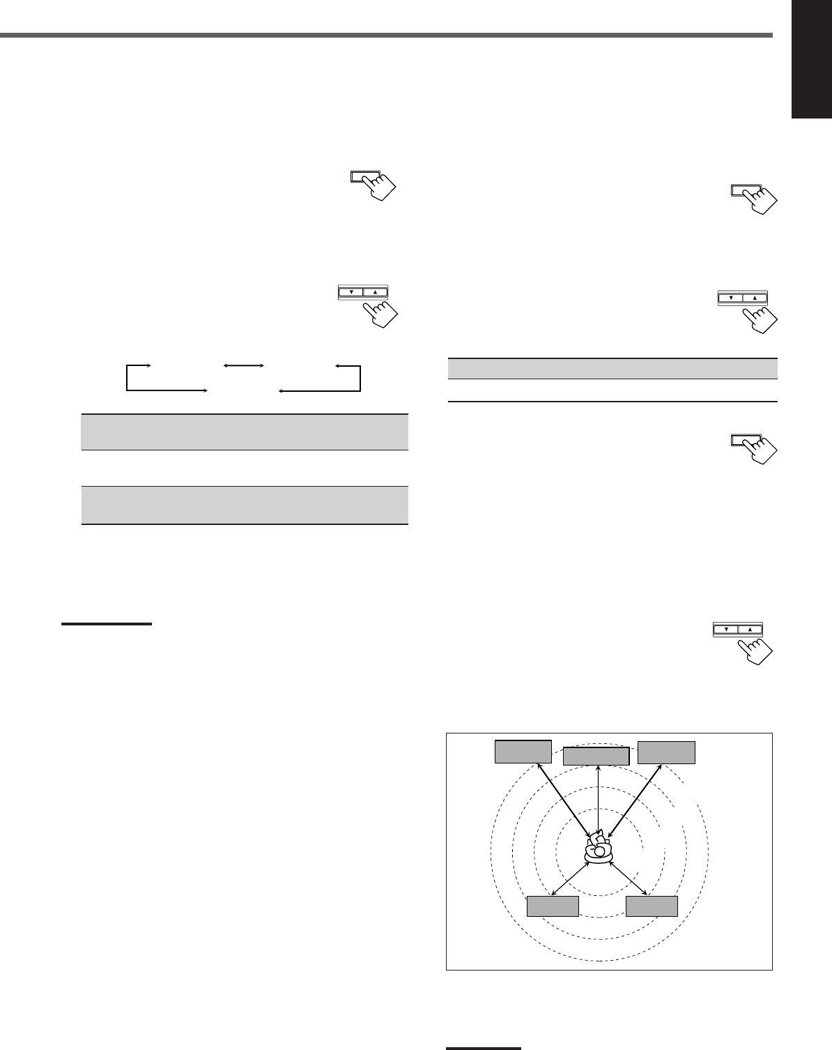
Example: In this case,
set “FRNT DIS” to “3.0m” or “10FT,”
set “CNTR DIS” to “2.7m” or “9FT” and,
set “REAR DIS” to “2.4m” or “8FT.”
Note:
If you have selected “NONE” for the center and rear speakers
setting, you cannot set the speaker distance for the center and rear
speakers.
T SETTING
Speaker size
Register the sizes of all the connected speakers.
•When you change your speakers, register the information about the
speakers again.
1
Press SETTING repeatedly until
“FRNT SP (Front speaker),” “CNTR
SP (Center speaker),” or “REAR SP
(Rear speaker)” (with the current setting)
appears on the display.
2
Press CONTROL UP 5/DOWN ∞ to
select the appropriate item about the
speaker selected in the above step.
•Each time you press the button, the display
changes as follows:
LARGE : Select this when the speaker size is relatively large.
(See “Notes” below.)
SMALL : Select this when the speaker size is relatively small.
(See “Notes” below.)
NONE : Select this when you have not connected a speaker.
(Not selectable for the front speakers)
3
Repeat steps
1
and
2
to select the appropriate
items for other speakers.
Notes:
•Keep the following comment in mind as reference when adjusting.
–If the size of the cone speaker unit built in your speaker is greater
than 12 cm (4
3
/
4
inches), select “LARGE,” and if it is smaller than
12 cm (4
3
/
4
inches), select “SMALL.”
•If you have selected “NO” for the subwoofer setting, you can only
select “LARGE” for the front speaker setting.
•If you have selected “SMALL” for the front speaker setting, you
cannot select “LARGE” for the center and rear speaker settings.
SETTING
CONTROL
DOWN UP
SETTING
CONTROL
DOWN UP
3.0 m
(10 feet)
Left front
speaker Right front
speaker
Right rear
speaker
Left rear
speaker
Center speaker
2.7 m
(9 feet)
2.4 m
(8 feet)
2.1 m
(7 feet)
CONTROL
DOWN UP
LARGE SMALL
NONE
EN08-17.RX-6020V[C]_f 02.1.8, 9:15 AM13
14
English
SETTING
CONTROL
DOWN UP
Dynamic range compression
You can compress the dynamic range (difference between maximum
sound and minimum sound) of the reproduced sound. This is useful
when enjoying surround sound at night.
•This function takes effect only when playing back a source
encoded with Dolby Digital.
1
Press SETTING repeatedly until
“D. COMP (Dynamic range
compression)” (with the current setting)*
appears on the display.
*“MID” is the initial setting. If you have already changed the
setting, another setting will be shown.
2
Press CONTROL UP 5/DOWN ∞
to select the appropriate compression
level.
•Each time you press the button, the display changes
as follows:
OFF : Select this when you want to enjoy surround with its
full dynamic range. (No effect applied.)
MID : Select this when you want to reduce the dynamic range
a little.
MAX : Select this when you want to apply the compression
effect fully. (Useful at night.)
Basic Settings
Crossover frequency
Small speakers cannot reproduce the bass sounds efficiently. If you
use a small speaker in any position, this receiver automatically
reallocates the bass sound elements assigned from small speakers to
large speakers.
To use this function properly, set this crossover frequency level
according to the size of the small speaker connected.
•If you have selected “LARGE” for all speakers, this function will
not take effect.
•Crossover frequency is not valid for DVD MULTI playback mode
and HEADPHONE mode.
1
Press SETTING repeatedly until “CROSS
(Crossover)” (with the current setting)*
appears on the display.
*“100HZ” is the initial setting. If you have already changed the
setting, another frequency will be shown.
2
Press CONTROL UP 5/DOWN ∞ to
select the crossover frequency level you
like to use.
•Each time you press the button, the crossover
frequency level changes as follows:
Low frequency effect attenuator
If the bass sound is distorted while playing back software using
Dolby Digital or DTS Digital Surround, follow the procedure
below:
•Low frequency effect attenuator is not valid for the DVD MULTI
playback mode.
•This function takes effect only when the subwoofer (LFE) signals
come in, (with “SUBWOOFER” set to “YES”).
1
Press SETTING repeatedly until “LFE
ATT (Low Frequency Effect Attenuator)”
(with the current setting)* appears on the
display.
*“0dB” is the initial setting. If you have already changed the
setting, “–10dB” will be shown.
2
Press CONTROL UP 5/DOWN ∞ to
select the low frequency effect
attenuator level.
•Each time you press the button, the setting
alternates between “0dB” and “–10dB.”
0dB : Normally select this.
–10dB : Select this when the bass sound is distorted.
SETTING
CONTROL
DOWN UP
SETTING
CONTROL
DOWN UP
100HZ
80HZ 120HZ
150HZ200HZ
OFF MID
MAX
EN08-17.RX-6020V[C]_f 02.1.8, 9:15 AM14
15
English
Once each of following settings has been adjusted, this receiver
memorizes the adjustments for each source.
Attenuating the Input Signal
When the input level of the analog source is too high, sounds will
be distorted. If this happens, you need to attenuate the input signal
level to prevent the sound distortion.
1
Press and hold INPUT ATT (INPUT
ANALOG) so that the INPUT ATT
indicator lights up on the display.
•Each time you press and hold the button, the Input Attenuator
mode turns on (“INPUT ATT ON”) or off (“INPUT
NORMAL”).
Note:
When selecting “DVD MULTI” as the source, this effect does not work.
Adjusting the Front Speakers
Output Balance
If the sounds you hear from the front right and left speakers are
unequal, you can adjust the speaker output balance.
Before you start, remember...
There is a time limit in doing the following steps. If the setting is
canceled before you finish, start from step
1
again.
1
Press ADJUST repeatedly until
“BALANCE” (with the current setting)*
appears on the display.
*“CNTR (Center)” is the initial setting. If you have already
changed the setting, another setting will be shown.
2
Press CONTROL UP 5/DOWN ∞
to adjust the balance.
•Pressing CONTROL UP 5 decreases the
left channel output from “CNTR (Center)”
to “L–21.”
•Pressing CONTROL DOWN ∞ decreases
the right channel output from “CNTR (Center)” to “R–21.”
Adjusting the Tone
You can adjust the bass and treble sounds as you like.
Before you start , remember...
There is a time limit in doing the following steps. If the setting is
canceled before you finish, start from step
1
again.
Sound Adjustments
SUBWOOFER +/–
SOUND
Front Panel Remote Control
ADJUST
FM MODE
A/V CONTROL
RECEIVER
AUDIO
TV
VCR
DVD
TEST
EFFECT
MENU
ENTER
RETURN
SOUND
SLEEP
CENTER
REAR L
SUBWOOFER
CD–DISC
REC PAUSE
TAPE/CDR CD DVD DVD MULTI
FM/AM
FM MODE
DIMMER TV/VIDEO
SURROUND
ON/OFF
MODE
MUTING
VCR CH TV CH
VOLUME
TV SOUND VCR ANALOG
/DIGITAL
REAR R
100
1
4
7/P
10
2
5
8
0
3
6
9
10
REMOTE CONTROL RM-SRX6020J
REW FF
TV VOLUME
STANDBY/ON
INPUT ANALOG
INPUT ATT
Display
INPUT ATT ADJUST CONTROL
UP 5/DOWN ∞
Remote
NOT
Remote
NOT
Remote
NOT
CONTROL
DOWN UP
ADJUST
CONTROL
DOWN UP
SOUND
CONTROL
DOWN UP
ADJUST
1
Press ADJUST repeatedly until “BASS”
or “TREBLE” (with the current setting)*
appears on the display.
*“0” is the initial setting. If you have already changed the
setting, another number (level) will be shown.
BASS : To adjust the bass (–10 to +10).
TREBLE : To adjust the treble (–10 to +10).
2
Press CONTROL UP 5/DOWN ∞ to
adjust the bass or treble sound level.
•Each time you press the button, the sound
level changes by ±2 steps.
Adjusting the Subwoofer Output Level
You can adjust the subwoofer output level if you have connected a
subwoofer and set the subwoofer information correctly—“YES.”
On the front panel:
Before you start, remember...
There is a time limit in doing the following steps. If the setting is
canceled before you finish, start from step
1
again.
1
Press ADJUST repeatedly until
“SUBWFR (Subwoofer)” (with the
current setting)* appears on the display.
*“0” is the initial setting. If you have already changed the
setting, another number (level) will be shown.
2
Press CONTROL UP 5/DOWN ∞ to
adjust the subwoofer output level
(–10 to +10).
From the remote control:
1
Press SOUND.
10 keys are activated for sound adjustments.
2
Press SUBWOOFER +/– to adjust
the subwoofer output level
(–10 to +10).
Note:
Subwoofer output level cannot be adjusted when using headphones.
SUBWOOFER
010
100
DVDDVD MULTI VCR TV SOUND
ADJUST
RX-6020V
AUDIO/VIDEO CONTROL RECEIVER
SETTING
MASTER VOLUME
CONTROL
DOWN UP
CD TAPE/CDR
SOURCE NAME
INPUT DIGITALINPUT ANALOG
SPEAKERS ON/OFF
SURROUND MODE
PHONES
SURROUND ON/OFF
FM/AM TUNING
STANDBY
FM/AM PRESET FM MODE
MEMORY
INPUT ATT
FM AM
STANDBY/ON
LC
S.WFR
LS RS
CH-
S
LFE
SPK
PRO LOGIC ΙΙ DSP H.PHONE
AUTO MUTING
TUNED STEREO
VOLUME
INPUT ATT
SLEEP
DIGITAL AUTO
ANALOG
DIGITAL
LINEAR PCM
R
EN08-17.RX-6020V[C]_f 02.1.8, 9:15 AM15
16
English
Tuning in Stations
1
Press FM or AM (FM/AM) to select the band.
The last received station of the selected band is tuned in.
2
Press FM/AM TUNING 5/∞
(up/down) repeatedly until you find
the frequency you want.
•Pressing FM/AM TUNING 5 (up)
increases the frequency.
•Pressing FM/AM TUNING ∞ (down)
decreases the frequency.
Notes:
•When you press and hold FM/AM TUNING
5
/
∞
(up/down) for few
seconds in step
2
, the frequency keeps changing until a station is
tuned in.
•When a station of sufficient signal strength is tuned in, the TUNED
indicator lights up on the display.
•When an FM stereo program is received, the STEREO indicator
also lights up.
Tuner Operations
Front Panel Remote Control
Display 10 keys
FM MODE
FM/AM
Remote
NOT
Using Preset Tuning
Once a station is assigned to a channel number, the station can be
quickly tuned. You can preset up to 30 FM and 15 AM stations.
To store the preset stations
Before you start, remember...
There is a time limit in doing the following steps. If the setting is
canceled before you finish, start from step
2
again.
1
Tune in the station you want to preset
(see “Tuning in Stations” on the left).
•If you want to store the FM reception mode for each preset
station, select the FM reception mode. See “Selecting the FM
Reception Mode” on page 17.
2
Press MEMORY.
The “CH-” indicator lights up and the channel
number position starts flashing on the display for
about 5 seconds.
3
Press FM/AM PRESET 5/∞ (up/
down) to select a channel number
while the channel number position
is flashing.
LC
S.WFR
LS RS
CH-
S
LFE
SPK AUTO MUTING
TUNED STEREO
VOLUME
ANALOG
R
MEMORY
LC
S.WFR
LS RS
CH-
S
LFE
SPK AUTO MUTING
TUNED STEREO
VOLUME
ANALOG
R
LC
S.WFR
LS RS
CH-
S
LFE
SPK AUTO MUTING
TUNED STEREO
VOLUME
ANALOG
R
FM/AM PRESET
MEMORY FM, AM
FM MODE
FM MODE
A/V CONTROL
RECEIVER
AUDIO
TV
VCR
DVD
TEST
EFFECT
MENU
ENTER
RETURN
SOUND
SLEEP
CENTER
REAR L
SUBWOOFER
CD–DISC
REC PAUSE
TAPE/CDR CD DVD DVD MULTI
FM/AM
FM MODE
DIMMER TV/VIDEO
SURROUND
ON/OFF
MODE
MUTING
VCR CH TV CH
VOLUME
TV SOUND VCR ANALOG
/DIGITAL
REAR R
100
1
4
7/P
10
2
5
8
0
3
6
9
10
REMOTE CONTROL RM-SRX6020J
REW FF
TV VOLUME
STANDBY/ON
FM/AM
PRESET
5/∞
(up/down)
FM/AM
TUNING
5/∞
(up/down)
LC
S.WFR
LS RS
CH-
S
LFE
SPK AUTO MUTING
TUNED STEREO
VOLUME
ANALOG
R
Ex.: When the FM band is selected.
On the front panel From the remote control
FM AM
FM/AM
FM/AM TUNING
Remote
NOT
DVDDVD MULTI VCR TV SOUND
ADJUST
RX-6020V
AUDIO/VIDEO CONTROL RECEIVER
SETTING
MASTER VOLUME
CONTROL
DOWN UP
CD TAPE/CDR
SOURCE NAME
INPUT DIGITALINPUT ANALOG
SPEAKERS ON/OFF
SURROUND MODE
PHONES
SURROUND ON/OFF
FM/AM TUNING
STANDBY
FM/AM PRESET FM MODE
MEMORY
INPUT ATT
FM AM
STANDBY/ON
LC
S.WFR
LS RS
CH-
S
LFE
SPK
PRO LOGIC ΙΙ DSP H.PHONE
AUTO MUTING
TUNED STEREO
VOLUME
INPUT ATT
SLEEP
DIGITAL AUTO
ANALOG
DIGITAL
LINEAR PCM
R
EN08-17.RX-6020V[C]_f 02.1.8, 9:15 AM16
17
English
4
Press MEMORY again while the
selected channel number is flashing
on the display.
The selected channel number stops flashing.
The station is assigned to the selected channel number.
5
Repeat steps
1
to
4
for storing more stations.
To erase a stored preset station
Storing a new station on a used number erases the previously stored
one.
To tune in a preset station
On the front panel:
1
Press FM or AM to select the
band.
The last received station of the
selected band is tuned in.
2
Press FM/AM PRESET 5/∞
(up/down) repeatedly until you find
the channel you want.
•Pressing FM/AM PRESET 5 (up)
increases the channel numbers.
•Pressing FM/AM PRESET ∞ (down)
decreases the channel numbers.
From the remote control:
1
Press FM/AM to select the band (FM or
AM).
The last received station of the selected band is tuned
in and 10 keys now work for tuner operation.
•Each time you press the button, the band
alternates between FM and AM.
2
Press 10 keys to select a preset
channel number.
•For channel number 5, press 5.
•For channel number 15, press +10 then 5.
•For channel number 20, press +10 then 10.
•For channel number 30, press +10, +10,
then 10.
Note:
When you use 10 keys on the remote control, be sure that they are
activated for the tuner, not for the CD player and others. (See page
28.)
LC
S.WFR
LS RS
CH-
S
LFE
SPK AUTO MUTING
TUNED STEREO
VOLUME
ANALOG
R
MEMORY
FM/AM PRESET
FM/AM
TEST
EFFECT
MENU
ENTER
CENTER
REAR L
SUBWOOFER
REAR R
1
4
7/P
10
2
5
8
0
3
6
9
10
100
RETURN
LC
S.WFR
LS RS
CH-
S
LFE
SPK AUTO MUTING
TUNED STEREO
VOLUME
ANALOG
R
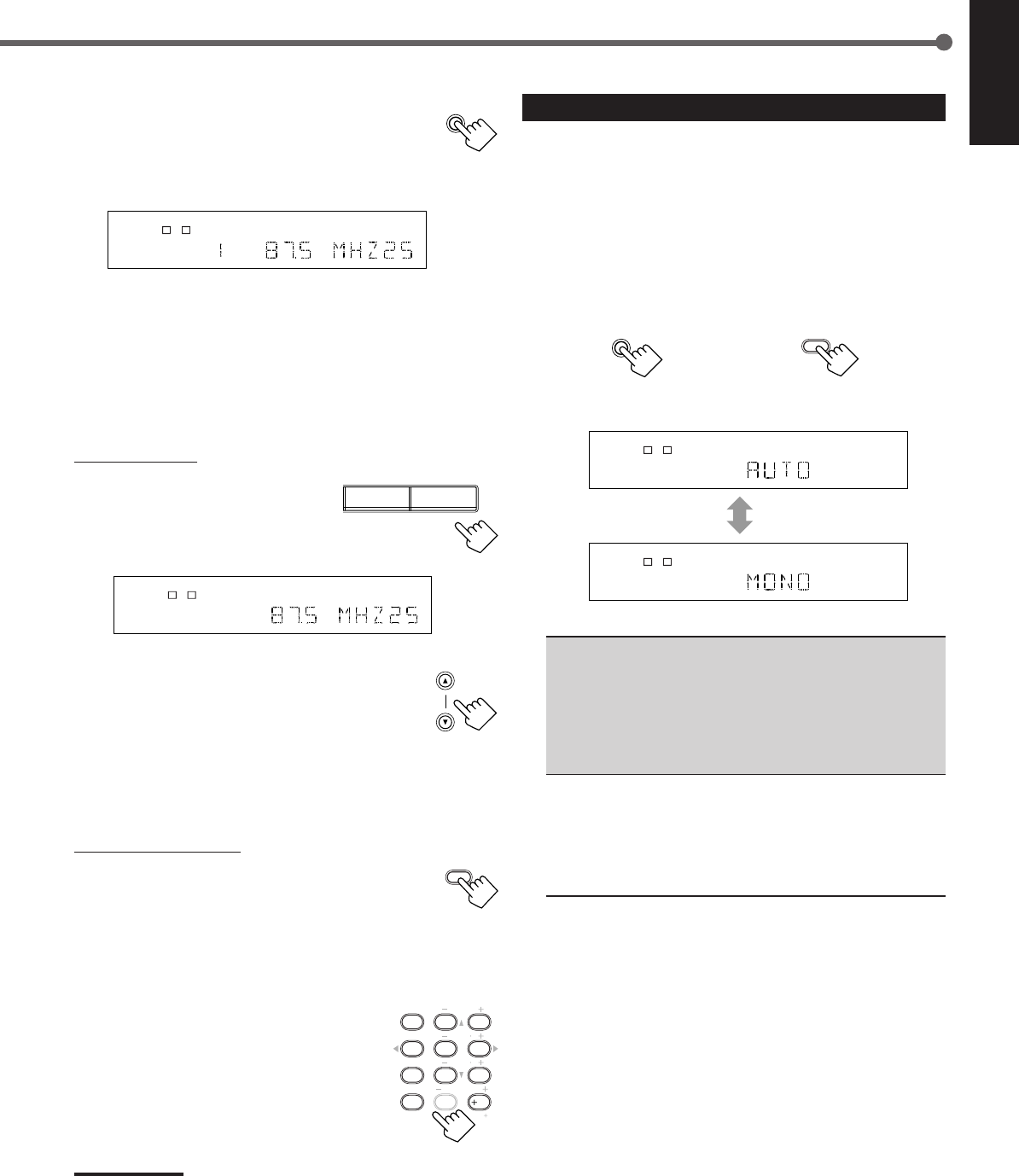
Selecting the FM Reception Mode
When an FM stereo broadcast is hard to receive or noisy, you can
change the FM reception mode while receiving an FM broadcast.
•You can store the FM reception mode for each preset station (see
page 16).
1
While listening to an FM station, press
FM MODE.
•Each time you press the button, the FM reception mode
alternates between “AUTO” and “MONO.”
AUTO : Normally select this.
When a program is broadcasted in stereo, you will
hear stereo sound; when in monaural, you will
hear monaural sounds. This mode is also useful to
suppress static noise between stations. The AUTO
MUTING indicator lights up on the display.
(Initial Setting)
MONO : Select this to improve the reception (but stereo
effect will be lost).
In this mode, you will hear noise while tuning into
the stations. The AUTO MUTING indicator goes
off from the display. (The STEREO indicator also
goes off.)
FM MODE
From the remote control
FM MODE
On the front panel
LC
S.WFR
LS RS
CH-
S
LFE
SPK AUTO MUTING
TUNED STEREO
ANALOG
R
LC
S.WFR
LS RS
CH-
S
LFE
SPK TUNED
ANALOG
R
FM AM
EN08-17.RX-6020V[C]_f 02.1.8, 9:15 AM17
18
English
*
Manufactured under license from Dolby Laboratories. “Dolby,” “Pro
Logic,” and the double-D symbol are trademarks of Dolby
Laboratories. Confidential Unpublished Works. ©1992–1997 Dolby
Laboratories, Inc. All rights reserved.
Creating Realistic Sound Fields
You can use the following Surround modes to reproduce a realistic
sound field:
■Dolby Surround
•Dolby Pro Logic II
•Dolby Digital
■DTS Digital Surround
■DAP modes
■All Channel Stereo
■ Dolby Surround
Dolby Pro Logic II*
Dolby Pro Logic II has a newly developed multichannel playback
format to decode all 2 channel sources—regular stereo source and
Dolby Surround encoded source—into 5.1 channel.
Matrix-based encoding/decoding method for Dolby Pro Logic II
makes no limitation for the cutoff frequency of the rear treble and
enables stereo rear sound compared to conventional Dolby Pro
Logic.
Dolby Pro Logic II enables to reproduce spacious sound from
original sound without adding any new sounds and tonal colorations.
Dolby Pro Logic II has two modes—Movie mode and Music mode:
Pro Logic II Movie (PL II MOVIE)—suitable for reproduction of
Dolby Surround encoded sources bearing the mark
DOLBY SURROUND
.
You can enjoy soundfield very close to the one created with discrete
5.1 channel sounds.
Pro Logic II Music (PL II MUSIC)—suitable for reproduction of
any 2 channel stereo music sources. You can enjoy wide and deep
sound by using this mode. For this mode, Panorama control can be
selected, which gives “wraparound” sound effect with side-wall
image.
•When Dolby Pro Logic II is activated, PRO LOGIC II
indicator lights up on the display.
Dolby Digital*
Used to reproduce multichannel sound tracks of the software
encoded with Dolby Digital (
DIGITAL
).
•To enjoy the software encoded with Dolby Digital, connect the
source component using the digital terminal on the rear of this
receiver. (See page 7.)
Dolby Digital 5.1 ch encoding method (so-called discrete
multichannel digital audio format) records and digitally compresses
the left front channel, right front channel, center channel, left rear
channel, right rear channel, and LFE channel signals.
Since each channel is completely independent from the other
channel signals to avoid interference, you can obtain much better
sound quality with much stereo and surround effects.
Note:
Dolby Digital software can be roughly grouped into two categories
—multichannel (up to “5.1” ch) and 2 channel software. To enjoy
surround sounds while playing Dolby Digital 2 ch software, you can
use Dolby Pro Logic II.
■ DTS Digital Surround**
Used to reproduce multichannel sound tracks of the software
encoded with DTS Digital Surround ( ).
•To enjoy the software encoded with DTS Digital Surround,
connect the source component using the digital terminal on the
rear of this receiver. (See page 7.)
DTS Digital Surround is another discrete multichannel digital
audio format available on CD, LD, and DVD software.
Compared to Dolby Digital, audio compression ratio is relatively
low. This fact allows DTS Digital Surround format to add breadth
and depth to the reproduced sounds. As a result, DTS Digital
Surround features natural, solid and clear sound.
**
Manufactured underlicense from Digital Theater Systems, Inc. US
PAT. No. 5,451,942 and other world-wide patents issued and
pending. “DTS” and “DTS Digital Surround” are trademarks of
Digital Theater Systems, Inc. Copyright 1996 Digital Theater
Systems, Inc. All rights reserved.
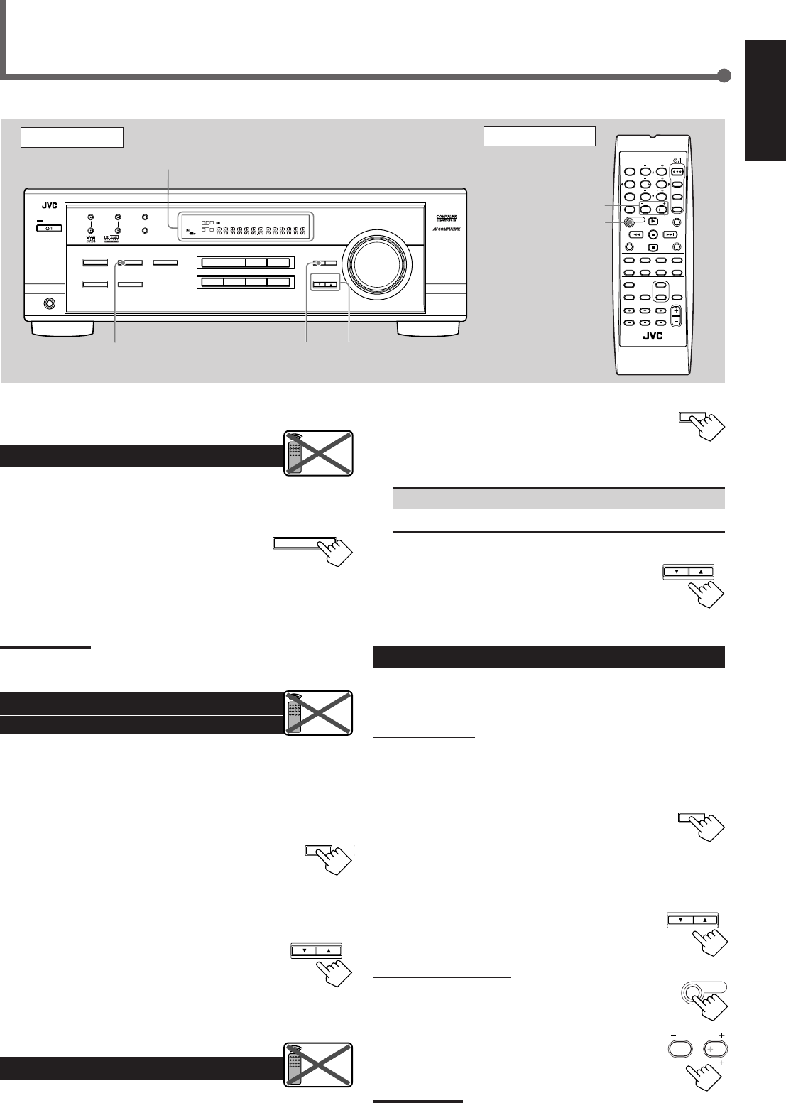
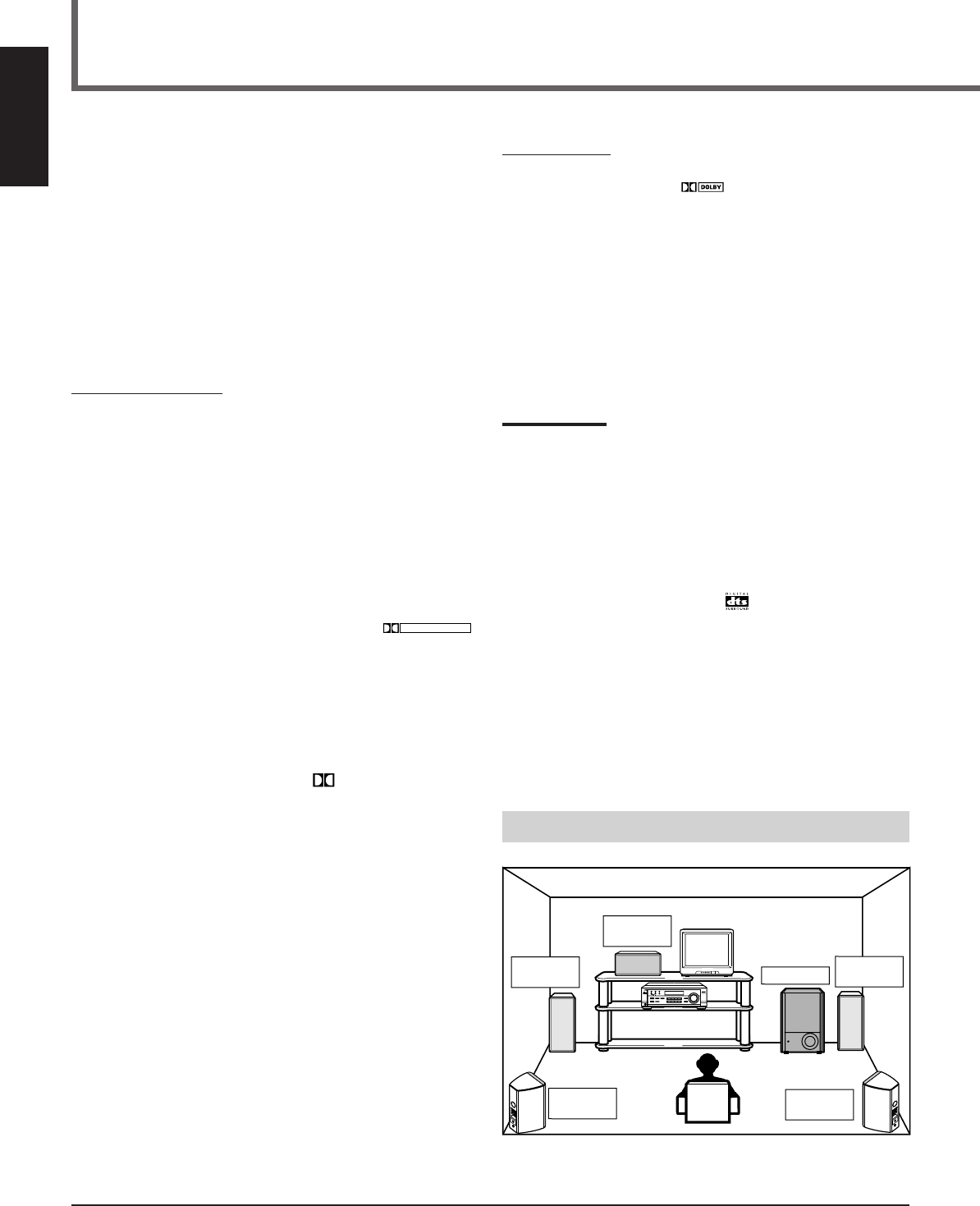
Typical Multichannel (5.1 ch) reproduction
Right rear
speaker
Left front
speaker Subwoofer
Center
speaker
Left rear
speaker
Right front
speaker
DVD VCR TV SOUND
ADJUST
RX-6020V AUDIO/VIDEO CONTROL RECEIVER
SETTING
MASTER VOLUME
CONTROL
DOWN UP
CD TAPE/CDR
SOURCE NAME
INPUT DIGITALINPUT ANALOG
SPEAKERS ON/OFF
SURROUND MODE
PHONES
SURROUND ON/OFF
FM/AM TUNING
STANDBY
FM/AM PRESET FM MODE
MEMORY
INPUT ATT
AM
DIGITAL
SURROUND
STANDBY/ON
DVD MULTI
FM
EN18-23.RX-6020V[C]_f 02.1.8, 9:15 AM18
19
English
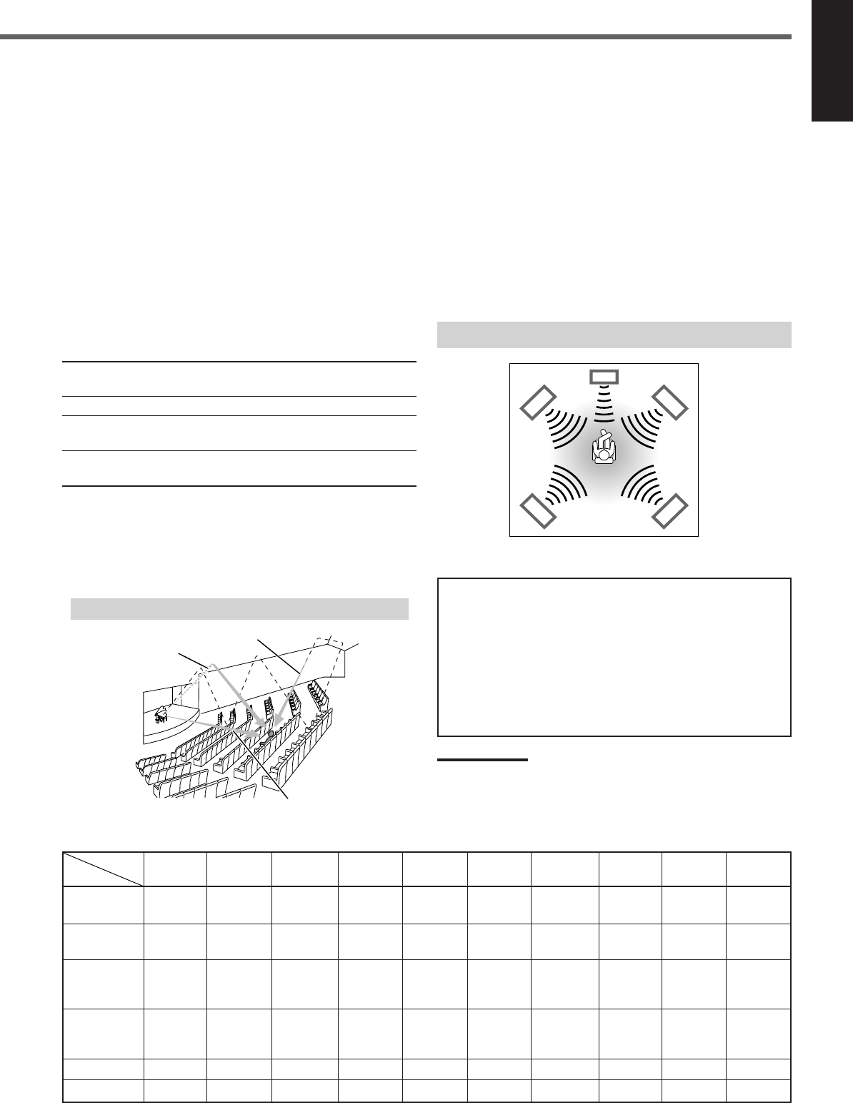
■ DAP (Digital Acoustic Processor) modes
DAP modes have been designed to create important acoustic
surround elements.
The sound heard in a live club, dance club, hall or pavilion consists
of direct sound and indirect sound—early reflections and reflections
from behind. Direct sounds reach the listener directly without any
reflection. On the other hand, indirect sounds are delayed by the
distances of the ceiling and walls (see the diagram below).
These indirect sounds are important elements of the acoustic
surround effects. The DAP mode can reproduce a realistic sound
field by adding these indirect sounds.
DAP modes can be used when the front and rear speakers are
connected to this receiver (without respect to the center speaker
connection: no sound comes out of the center speaker even if it is
connected).
The following DAP modes are provided with this receiver:
LIVE CLUB : Gives the feeling of a live music club with a low
ceiling.
DANCE CLUB : Gives a throbbing bass beat.
HALL : Gives clear vocal and the feeling of a concert
hall.
PAVILION : Gives the spacious feeling of a pavilion with a
high ceiling.
These DAP modes can be used to add the acoustic surround effects
while reproducing 2 channel stereo software—either analog or
digital except Dolby Digital and DTS Digital Surround—and can
give you a real “being there” feeling.
•When one of the DAP modes is selected, the DSP indicator lights
up on the display.
Available Surround modes for each input signal 䡬: Possible / ⳯: Impossible
Mode
SURROUND
DOLBY DTS PLII PLII LIVE DANCE HALL PAVILION ALL CH
Signals
OFF (stereo)
DIGITAL
SURROUND
MOVIE MUSIC CLUB CLUB STEREO
Dolby Digital 䡬䡬⳯⳯⳯⳯⳯ ⳯⳯⳯
(Multichannel)
Dolby Digital 䡬⳯⳯䡬䡬⳯⳯ ⳯⳯⳯
(2 channel)
DTS Digital
Surround 䡬⳯䡬⳯⳯⳯⳯ ⳯⳯⳯
(Multichannel)
DTS Digital
Surround 䡬⳯⳯䡬䡬⳯⳯ ⳯⳯⳯
(2 channel)
Linear PCM 䡬⳯⳯䡬䡬 䡬䡬 䡬䡬䡬
Analog 䡬⳯⳯䡬䡬 䡬䡬 䡬䡬䡬
■ All Channel Stereo
This mode can reproduce a larger stereo sound field using all the
connected (and activated) speakers.
All Channel Stereo can be used when the front and rear
speakers are connected to this receiver without respect to the
center speaker connection.
If the center speaker is connected and activated, the same phase of
the front left and right signals are output through the center speaker.
All Channel Stereo can be used while reproducing 2 channel stereo
software, either analog or digital except Dolby Digital and DTS
Digital Surround.
•When All Channel Stereo is selected, the DSP indicator lights up
on the display.
DVD MULTI Playback Mode
This receiver provides the DVD MULTI Playback Mode for
reproducing the analog discrete 5.1 channel output mode of the
DVD player or other equipment.
You can adjust speaker output levels while playing back a video
software such as a DVD using the analog discrete 5.1 channel
output mode.
•For connecting analog discrete output jacks, see page 7.
•For details on the DVD MULTI Playback Mode, see page 24.
Note:
When you select “DVD MULTI” as the source to play, Surround mode
is canceled, and the SURROUND ON/OFF and SURROUND MODE
buttons do not work.
All Channel Stereo reproduction
Sound reproduced from All Channel Stereo
Creating sound field
Early reflections
Reflections from behind
Direct sounds
EN18-23.RX-6020V[C]_f 02.1.8, 9:15 AM19
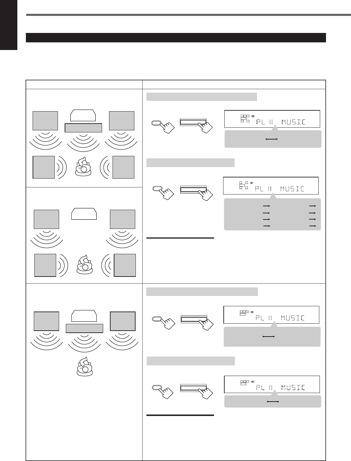
20
English
About Relations between Speaker Layout and Surround Modes
Available Surround modes will vary depending on how many speakers are used with this receiver.
Make sure that you have set the speaker information correctly (see pages 12 to 14).
•If only front speakers are connected, you cannot use any Surround modes.
•If rear speakers are not connected, you cannot use the DAP modes and All Channel Stereo.
Creating Realistic Sound Fields
Speaker Layout Available Surround modes
When the center and rear speakers
are connected (5 channels):
Ex.: “PL II MUSIC” has been selected.
Turning on or off Surround modes
Each time you press SURROUND ON/OFF, Surround modes turn on or off.
L
S.WFR
SPK
PRO LOGIC ΙΙ DSP H.PHONE
AUTO MUTING
TUNED STEREO
INPUT ATT
DIGITAL AUTO
LINEAR PCM
R
SURROUND OFF
Last selected
Surround mode
L
S.WFR
SPK
PRO LOGIC ΙΙ DSP H.PHONE
AUTO MUTING
TUNED STEREO
INPUT ATT
DIGITAL AUTO
LINEAR PCM
R
PL II MOVIE
LIVE CLUB DANCE CLUB
ALL CH STEREO
PAVILION
HALL
(Back to the beginning)
PL II MUSIC
Selecting Surround modes
Each time you press SURROUND MODE, Surround modes change as follows:
SURROUND
MODE
SURROUND MODE
(Front panel)
(Remote)
Turning on or off Surround modes
Each time you press SURROUND ON/OFF, Surround modes turn on or off.
Ex.: “PL II MUSIC” has been selected.
L
S.WFR
SPK
PRO LOGIC ΙΙ DSP H.PHONE
AUTO MUTING
TUNED STEREO
INPUT ATT
DIGITAL AUTO
LINEAR PCM
R
SURROUND OFF
PL II MOVIE
or
PL II MUSIC
Front
speaker
When the center speaker is connected
(3 channels):
TV
Rear
speaker
Front
speaker
Rear
speaker
When the rear speakers are connected
(4 channels):
TV
Center speaker
Front
speaker
Front
speaker
Rear
speaker
Rear
speaker
Front
speaker Center speaker
Front
speaker
TV
Selecting Surround modes
Each time you press SURROUND MODE, Surround modes change as follows:
Notes:
When the digital multichannel software such as Dolby Digital or DTS Digital
Surround is played back, the appropriate multichannel Surround mode is
automatically activated (“DOLBY DIGITAL” or “DTS SURROUND”) by pressing
SURROUND ON/OFF (with the digital input mode selected).
•For Dolby Digital 2 ch software, you need to select “PLII MUSIC” or “PLII MOVIE”
by pressing SURROUND MODE.
•For more details, see the table on page 19.
L
S.WFR
SPK
PRO LOGIC ΙΙ DSP H.PHONE
AUTO MUTING
TUNED STEREO
INPUT ATT
DIGITAL AUTO
LINEAR PCM
R
PL II MOVIE PL II MUSIC
Notes:
When the digital multichannel software such as Dolby Digital or DTS Digital
Surround is played back, the appropriate multichannel Surround mode is
automatically activated (“DOLBY DIGITAL” or “DTS SURROUND”) by pressing
SURROUND ON/OFF (with the digital input mode selected).
•For Dolby Digital 2 ch software, you need to select “PLII MUSIC” or “PLII MOVIE”
by pressing SURROUND MODE.
•For more details, see the table on page 19.
SURROUND MODE
(Remote) (Front panel)
(Front panel)(Remote)
SURROUND
ON/OFF
(Remote)
SURROUND ON/OFF
(Front panel)
SURROUND
ON/OFF
SURROUND ON/OFF
SURROUND
MODE
EN18-23.RX-6020V[C]_f 02.1.8, 9:15 AM20
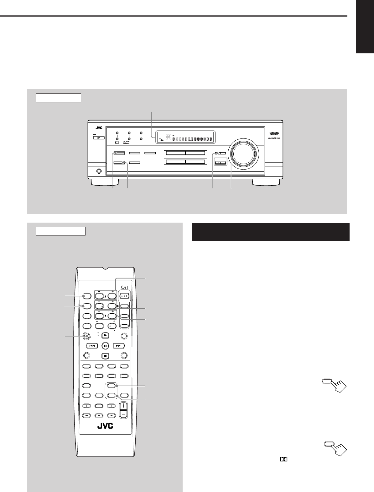
21
English
Before you start, remember...
•Make sure that you have set the speaker information correctly (see pages 12 to 14).
•You cannot adjust the center speaker output level when you have set “CNTR SP” to “NONE.”
•You cannot adjust the rear speaker output levels when you have set “REAR SP” to “NONE.”
•Remember not to change the speaker setting while using any Surround mode; otherwise, it may be canceled when you deactivate the
speakers required for Surround mode.
Using Dolby Pro Logic II, Dolby Digital and
DTS Digital Surround
Once you have adjusted the Surround modes, the adjustment is
memorized for each source.
•When playing back digital multichannel software (Dolby Digital
5.1 ch or DTS Digital Surround), the SURROUND MODE button
does not work.
From the remote control:
It will be convenient for you to use the remote control for
adjustments, since you can make adjustments from your listening
point by using the test signal.
•For selecting Panorama control for Pro Logic II Music, use the
buttons on the front panel.
1
Set the analog or digital input mode for the source
you like to listen and start playing.
When playing back software encoded with Dolby Digital and
DTS Digital Surround, select the digital input mode (see page
11).
2
Press SURROUND ON/OFF to
activate Surround mode.
Each time you press the button, Surround mode
turns on and off alternately.
•If you are playing back software encoded with Dolby Digital
multichannel, “DOLBY DIGITAL” is selected.
•If you are playing back software encoded with DTS Digital
Surround, “DTS SURROUND” is selected.
•If you are playing back any software other
than above, you can select “PL II MUSIC” or
“PL II MOVIE” according to the source by
pressing SURROUND MODE. ( PRO LOGIC II
indicator lights up on the display.)
If you like to adjust sound, go to step
3
.
Remote Control
SURROUND
ON/OFF
SURROUND
MODE
EFFECT
TEST
REAR•R +/–
REAR•L +/–
CENTER +/–
SOUND
FM MODE
A/V CONTROL
RECEIVER
AUDIO
TV
VCR
DVD
TEST
EFFECT
MENU
ENTER
RETURN
SOUND
SLEEP
CENTER
REAR L
SUBWOOFER
CD–DISC
REC PAUSE
TAPE/CDR CD DVD DVD MULTI
FM/AM
FM MODE
DIMMER TV/VIDEO
SURROUND
ON/OFF
MODE
MUTING
VCR CH TV CH
VOLUME
TV SOUND VCR ANALOG
/DIGITAL
REAR R
100
1
4
7/P
10
2
5
8
0
3
6
9
10
REMOTE CONTROL RM -SRX6020J
REW FF
TV VOLUME
STANDBY/ON
Front Panel
Display
SURROUND
ON/OFF
SURROUND
MODE
ADJUST CONTROL
UP 5/DOWN ∞
TO BE CONTINUED ON THE NEXT PAGE
SURROUND
ON/OFF
SURROUND
MODE
DVDDVD MULTI VCR TV SOUND
ADJUST
RX-6020V
AUDIO/VIDEO CONTROL RECEIVER
SETTING
MASTER VOLUME
CONTROL
DOWN UP
CD TAPE/CDR
SOURCE NAME
INPUT DIGITALINPUT ANALOG
SPEAKERS ON/OFF
SURROUND MODE
PHONES
SURROUND ON/OFF
FM/AM TUNING
STANDBY
FM/AM PRESET FM MODE
MEMORY
INPUT ATT
FM AM
STANDBY/ON
LC
S.WFR
LS RS
CH-
S
LFE
SPK
PRO LOGIC ΙΙ DSP H.PHONE
AUTO MUTING
TUNED STEREO
VOLUME
INPUT ATT
SLEEP
DIGITAL AUTO
ANALOG
DIGITAL
LINEAR PCM
R
EN18-23.RX-6020V[C]_f 02.1.8, 9:16 AM21
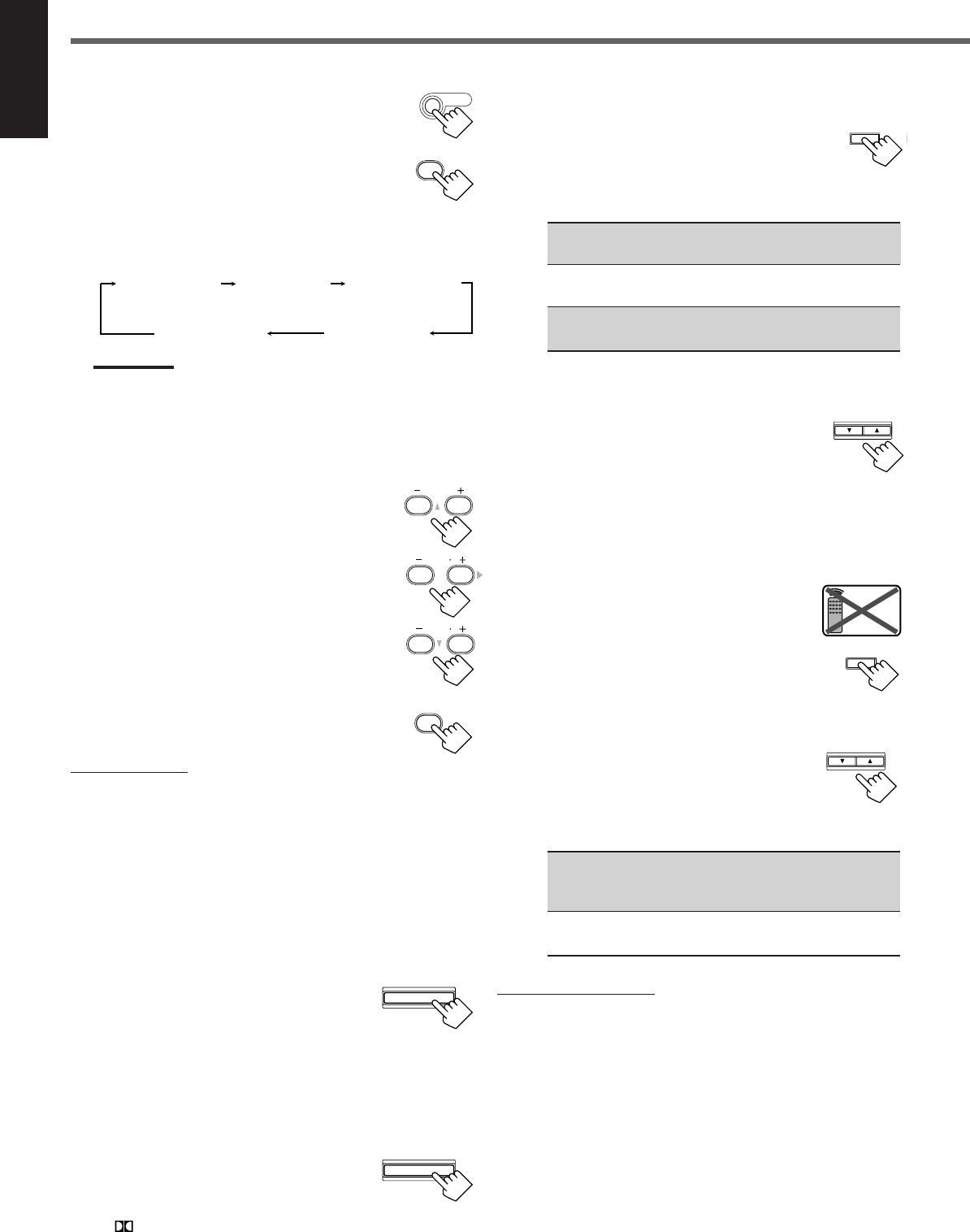
22
English
3
Press SOUND.
10 keys are activated for sound adjustments.
4
Press TEST to check if you can hear the
sounds through all the speakers at the
equal level.
“TEST TONE L” starts flashing on the
display, and a test tone comes out of the
speakers in the following order:
Notes:
•You can adjust the speaker output levels without outputting the
test tone.
•No test tone comes out of the center speaker when “CNTR SP”
is set to “NONE.”
•No test tone comes out of the rear speakers when “REAR SP”
is set to “NONE.”
5
Adjust the speaker output levels
(–10 to +10).
Adjust the center speakers and rear speakers levels
by comparing with the sound from the front
speakers.
•To adjust the center speaker level, press
CENTER +/–.
•To adjust the left rear speaker level, press
REAR•L +/–.
•To adjust the right rear speaker level, press
REAR•R +/–.
6
Press TEST again to stop the test
tone.
On the front panel:
You can also use the buttons on the front panel to adjust the
Surround modes. However, no test tone is available when using the
buttons on the front panel. So, make adjustments while listening to
the sound of the source played back.
1
Set the analog or digital input mode for the
source you like to listen and start playing.
When playing back software encoded with Dolby Digital and
DTS Digital Surround, select the digital input mode (see page
11).
2
Press SURROUND ON/OFF
repeatedly to activate Surround
mode.
Each time you press the button, Surround mode turns on and off
alternately.
•If you are playing back software encoded with Dolby Digital
multichannel, “DOLBY DIGITAL” is selected.
•If you are playing back software encoded with DTS Digital
Surround, “DTS SURROUND” is selected.
•If you are playing back any software other
than above, you can select “PL II MUSIC”
or “PL II MOVIE” according to the source
by pressing SURROUND MODE.
( PRO LOGIC II indicator lights up on the display.)
If you like to adjust sound, go to step
3
.
3
Adjust the speaker output levels.
1)
Press ADJUST repeatedly until one
of the following indications (with the
current setting)* appears on the
display.
CENTER :To adjust the center speaker output level
(–10 to +10).
REAR L : To adjust the left rear speaker output level
(–10 to +10).
REAR R : To adjust the right rear speaker output level
(–10 to +10).
*“0” is the initial setting. If you have already changed the
setting, another number (level) will be shown.
2)
Press CONTROL UP 5/
DOWN ∞ to adjust the selected
speaker output levels.
3)
Repeat steps
1)
and
2)
to adjust the other
speaker levels.
When you select “PL II MUSIC,” you can go to the
following adjustment.
4
Turn Panorama control on or off.
1)
Press ADJUST repeatedly until
“PANORAMA” (with the current
setting)* appears on the display.
*“OFF” is the initial setting. If you have
already changed the setting, “ON” will be shown.
2)
Press CONTROL UP 5/DOWN ∞
to select if you turn on or off
Panorama control.
•Each time you press the button, “ON” and
“OFF” change alternately.
ON : Select this when you like to enjoy
“wraparound” sound effect with side-wall
image.
OFF : Select this when you like to enjoy originally
recorded sounds.
To cancel Surround mode
Press SURROUND ON/OFF again so that “SURROUND OFF”
appears on the display.
•If Surround mode is canceled while playing back multichannel
digital software, all channel signals are mixed and output through
the front speakers (and subwoofer if you have connected a
subwoofer and set the subwoofer setting correctly—“YES”).
Creating Realistic Sound Fields
TEST
1
SOUND
TEST TONE L
(Left front speaker)
TEST TONE LS
(Left rear speaker)
TEST TONE RS
(Right rear speaker)
TEST TONE C
(Center speaker)
TEST TONE R
(Right front speaker)
SURROUND MODE
TEST
1
CENTER
23
REAR R
89
REAR L
56
ADJUST
CONTROL
DOWN UP
CONTROL
DOWN UP
ADJUST
Remote
NOT
SURROUND ON/OFF
EN18-23.RX-6020V[C]_f 02.1.8, 9:16 AM22
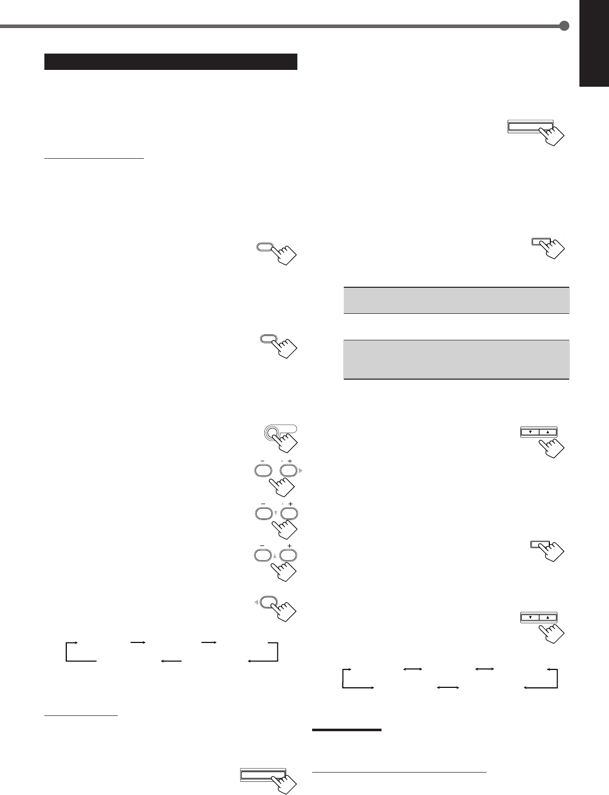
23
English
ADJUST
SURROUND MODE
CONTROL
DOWN UP
EFFECT 1 EFFECT 2 EFFECT 3
EFFECT 4
EFFECT 5
ADJUST
CONTROL
DOWN UP
SURROUND
ON/OFF
SURROUND
MODE
EFFECT 1 EFFECT 2 EFFECT 3
EFFECT 4
EFFECT 5
REAR R
89
REAR L
56
CENTER
23
SOUND
Using DAP Modes and All Channel Stereo
Once you have adjusted the DAP modes and All Channel Stereo, the
adjustment is memorized for each source.
•You cannot use the DAP modes and All Channel Stereo if no rear
speakers are connected and activated.
•You cannot adjust the effect level for All Channel Stereo.
From the remote control:
It will be convenient for you to use the remote control for
adjustments, since you can make adjustments from your listening
point.
1
Start playing 2 channel software—either analog
or Linear PCM—and select the source.
2
Press SURROUND ON/OFF to activate
Surround mode.
When Surround mode turns on, the last selected Surround mode
will be activated.
•Each time you press the button, Surround mode turns on and
off alternately.
3
Press SURROUND MODE repeatedly
until one of the DAP modes—“LIVE
CLUB,” “DANCE CLUB,” “HALL,”
“PAVILION”—or “ALL CH STEREO”
appears on the display.
The DSP indicator also lights up on the display.
If you like to adjust sound, go to step
4
.
4
Press SOUND.
10 keys are activated for sound adjustments.
5
Adjust the speakers output levels
(–10 to +10).
•To adjust the left rear speaker level, press
REAR•L +/–.
•To adjust the right rear speaker level, press
REAR•R +/–.
For “ALL CH STEREO” only:
•To adjust the center speaker level, press
CENTER +/–.
6
For DAP modes only:
Press EFFECT to select the effect level
(1 to 5) you want.
•Each time you press the button, the effect
level changes as follows:
As the number increases, the selected mode becomes stronger
(normally set it to “EFFECT 3”).
On the front panel:
1
Start playing 2 channel software—either analog
or Linear PCM—and select the source.
2
Press SURROUND ON/OFF to
activate Surround mode.
When Surround mode turns on, the last selected Surround mode
will be activated.
•Each time you press the button, Surround mode turns on and off
alternately.
3
Press SURROUND MODE
repeatedly until one of the DAP
modes—“LIVE CLUB,” “DANCE
CLUB,” “HALL,” “PAVILION,”—
or “ALL CH STEREO” appears on the display.
The DSP indicator also lights up on the display.
If you like to adjust sound, go to step
4
.
4
Adjust the speaker output levels.
1)
Press ADJUST repeatedly until one
of the following indications (with the
current setting)* appears on the
display.
REAR L : To adjust the left rear speaker output level
(–10 to +10).
REAR R : To adjust the right rear speaker output level
(–10 to +10).
CENTER : For “ALL CH STEREO” only—to adjust the
center speaker output level
(–10 to +10).
* “0” is the initial setting. If you have already changed the
setting, another number (level) will be shown.
2)
Press CONTROL UP 5/DOWN ∞
to adjust the selected speaker
output levels.
3)
Repeat steps
1)
and
2)
to adjust the
other speaker levels.
5
Only for DAP modes:
Adjust the DSP effect level.
1)
Press ADJUST repeatedly until
“EFFECT” (with the current
setting)* appears on the display.
*“EFFECT 3” is the initial setting. If you have already
changed the setting, another setting will be shown.
2)
Press CONTROL UP 5/DOWN ∞
to select the effect level (1 to 5) you
want.
•Each time you press the button, the effect
level changes as follows:
As the number increases, the selected mode becomes
stronger (normally set it to “EFFECT 3”).
Note:
You cannot select any DAP mode and All Channel Stereo for Dolby
Digital and DTS Digital Surround.
To cancel DAP modes and All Channel Stereo
Press SURROUND ON/OFF so that “SURROUND OFF” appears on
the display. The DSP indicator goes off.
SURROUND ON/OFF
EFFECT
4
EN18-23.RX-6020V[C]_f 02.1.8, 9:16 AM23
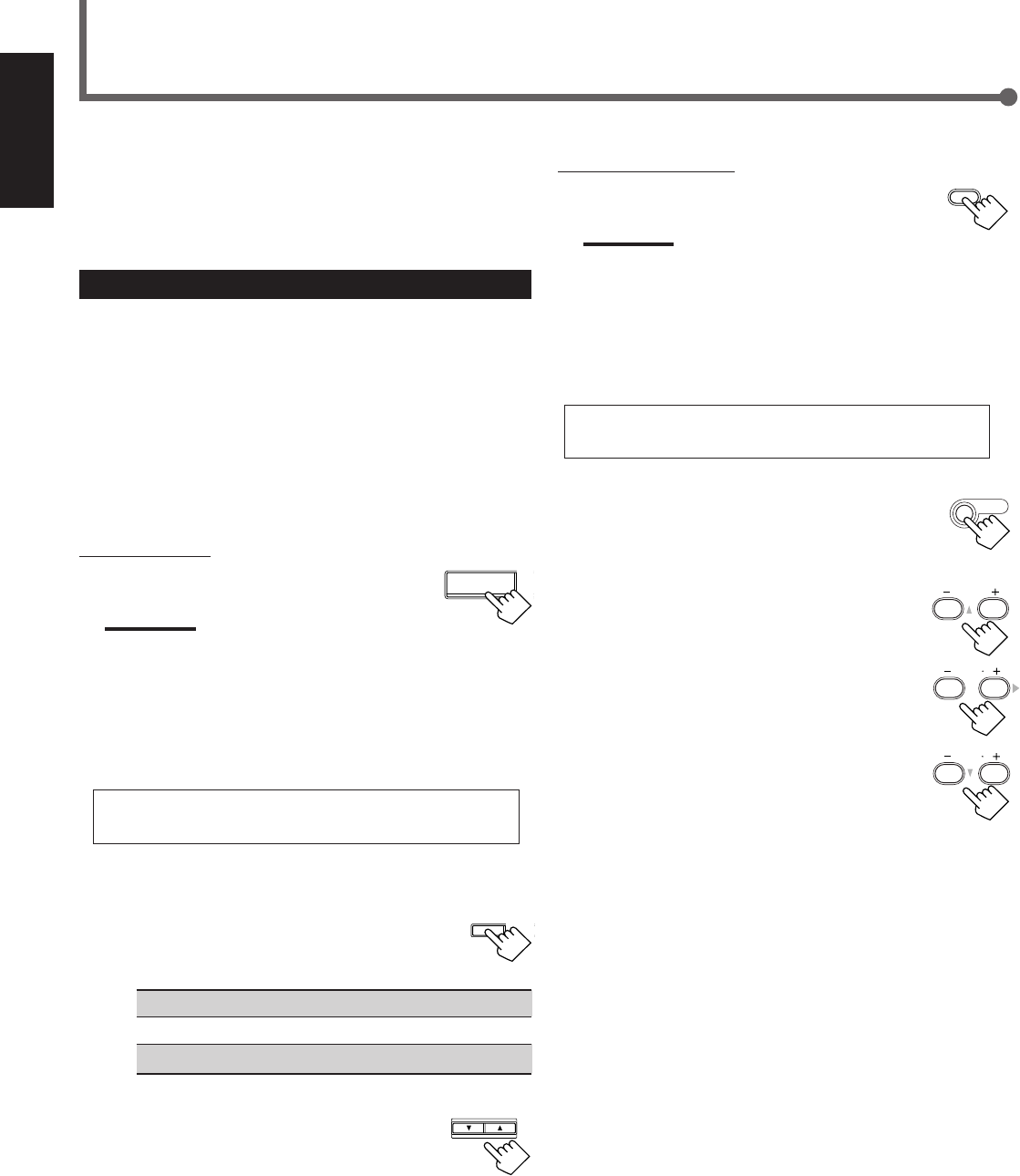
24
English
From the remote control:
1
Press DVD MULTI.
Note:
When you select “DVD MULTI” as the source to play, Surround
mode is canceled, and the SURROUND ON/OFF and
SURROUND MODE buttons do not work.
2
Select the analog discrete output mode on the
DVD player, and start playing a DVD.
•Refer to the manual supplied with your DVD player.
If you need to make any adjustment, go to the
following steps.
3
Press SOUND.
10 keys are activated for adjusting the sound.
4
Adjust the speaker output levels.
•To adjust the center speaker level, press
CENTER +/– (–10 to +10).
•To adjust the left rear speaker level, press
REAR•L +/– (–10 to +10).
•To adjust the right rear speaker level, press
REAR•R +/– (–10 to +10).
Using DVD MULTI Playback Mode
DVD MULTI
This receiver provides DVD MULTI Playback Mode for
reproducing the analog discrete output mode of the DVD player.
Before playing back a DVD, refer also to the manual supplied with
your DVD player.
Activating DVD MULTI Playback Mode
You can adjust DVD MULTI Playback Mode while playing back a
DVD with analog discrete output mode on a DVD player.
Once you have made adjustments, the receiver memorizes the
adjustments until you change them.
You also need to set the DVD player to the analog discrete output
mode.
Before you start, remember...
There is a time limit in doing the following steps. If the setting is
canceled before you finish, start from step
3
again.
On the front panel:
1
Press DVD MULTI.
Note:
When you select “DVD MULTI” as the source to play, Surround
mode is canceled, and the SURROUND ON/OFF and
SURROUND MODE buttons do not work.
2
Select the analog discrete output mode on the
DVD player, and start playing a DVD.
•Refer also to the manual supplied with the DVD player.
If you need to make any adjustment, go to the
following steps.
3
Adjust the speaker output levels.
1)
Press ADJUST repeatedly until one
of the following indications appears
on the display.
CENTER : To adjust the center speaker level.
REAR L : To adjust the left rear speaker level.
REAR R : To adjust the right rear speaker level.
2)
Press CONTROL UP 5/DOWN ∞
to adjust the selected speaker
output levels (–10 to +10).
3)
Repeat steps
1)
and
2)
to adjust the other
speaker output levels.
REAR R
89
CENTER
23
SOUND
CONTROL
DOWN UP
ADJUST
REAR L
56
DVD MULTI
EN24-32.RX-6020V[C]_f 02.1.8, 9:16 AM24
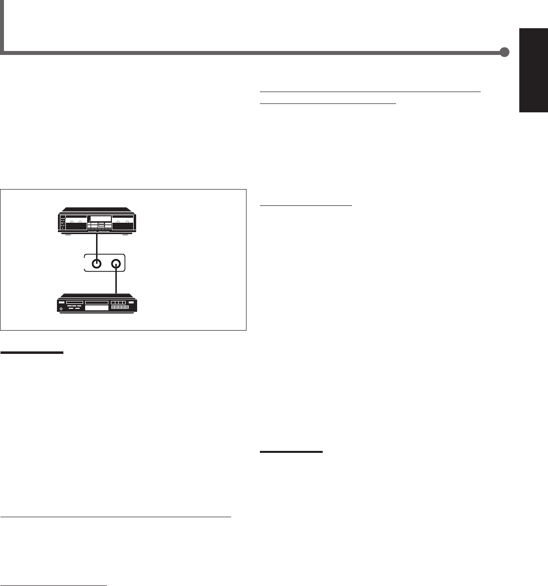
25
English
COMPU LINK-4
(SYNCHRO)
Cassette deck
or
CD recorder
CD player
The COMPU LINK remote control system allows you to operate
JVC’s audio components through the remote sensor on the receiver.
To use this remote control system, you need to connect JVC’s audio
components through the COMPU LINK–4 (SYNCHRO) jacks (see
below) in addition to the connections using cables with RCA pin
plugs (see page 6).
•Make sure that the AC power cords of these components are
unplugged before making connection. Plug the AC power cords
only after all connections are completed.
Notes:
•There are four versions of COMPU LINK remote control system.
This receiver is equipped with the fourth version—COMPU LINK-4.
This version is added systematic operations with the CD recorder
to the previous version—COMPU LINK-3.
•If your audio component has two COMPU LINK jacks, you can use
either one. If it has only one COMPU LINK jack, connect it so that it
is the last item in the series of components.
•To operate the cassette deck or CD recorder using the COMPU
LINK remote control system, set the source name correctly.
(See page 8.)
•Refer also to the manuals supplied with your audio components.
This remote control system allows you to use four functions listed
below.
Remote Control through the Remote Sensor on the Receiver
You can control the connected audio components through the
remote sensor on the receiver using this remote control. Aim the
remote control directly at the remote sensor on the receiver. For
details, see pages 28 and 29.
Automatic Source Selection
When you press the play (33
33
3) button on a connected component or
on its own remote control, the receiver automatically turns on and
changes the source to the component. On the other hand, if you
select a new source on the receiver or on the remote control, the
selected component begins playing immediately.
In both cases, the previously selected source continues playing
without sound for a few seconds.
Automatic Power On/Off (Standby): Only possible with the
COMPU LINK–3 and COMPU LINK–4
Both the CD player and cassette deck (or CD recorder) turn on and
off (standby) along with the receiver.
When you turn on the receiver, the CD player or cassette deck (or
CD recorder) will turn on automatically, depending on which
component has been previously selected.
When you turn off the receiver, both the CD player and cassette
deck (or CD recorder) will turn off (standby).
Synchronized Recording
Synchronized recording means the cassette deck starts recording as
soon as a CD begins playing.
To use synchronized recording, follow these steps:
1
Put a tape in the cassette deck and a disc in the
CD player.
2
Press the record (¶) button and the pause (8)
button on the cassette deck at the same time.
This puts the cassette deck into recording pause.
If you do not press the record (¶) button and pause (8) button at
the same time, the synchronized recording feature will not
operate.
3
Press the play (3) button on the CD player.
The source changes on the receiver, and as soon as play starts,
the cassette deck starts recording. When the play ends, the
cassette deck enters recording pause, and stops about 4 seconds
later.
Notes:
•During synchronized recording, the selected source cannot be
changed.
•If the power of any component is shut off during synchronized
recording, the COMPU LINK remote control system may not
operate properly. In this case, you must start again from the
beginning.
COMPU LINK Remote Control System
EN24-32.RX-6020V[C]_f 02.1.8, 9:16 AM25
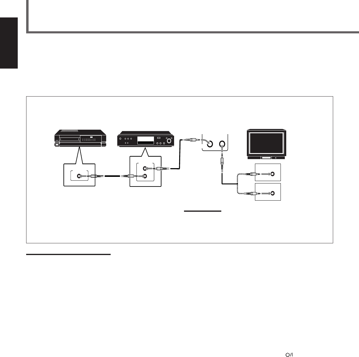
26
English
The AV COMPU LINK remote control system allows you to operate JVC’s video components through the remote sensor on the receiver.
To use this remote control system, you need to connect the video components you want to operate by following the diagram and the
procedure below.
•Make sure that AC power cords of these components are unplugged before connecting. Plug AC power cords only after all connections are
completed.
CONNECTIONS:
AV COMPU LINK Remote Control System
AV
COMPU LINK
AV
COMPU LINK
VHS
AV
COMPU LINK
DVD
AV
COMPU LINK EX
AV
COMPU LINK III
VCR DVD player TV
Note:
You can only connect to the TV with the AV COMPU LINK EX or AV
COMPU LINK III terminal.
The TV with AV COMPU LINK RECEIVER/AMP terminal will not be
used.
Notes:
•When connecting only the VCR and DVD player to this receiver, use the cable with monaural mini-plugs.
•You can connect only the TV with AV COMPU LINK EX or AV COMPU LINK–III to the AV COMPU LINK terminal.
•Refer also to the manuals supplied with your video components.
•Make sure that the remote control code of the VCR connected to the VCR jacks is set to code “A.”
1
Unplug your VCR, DVD player, TV, and this
receiver from the AC outlets.
2
Connect your VCR, DVD player, TV, and this
receiver using cables with the monaural mini-
plugs (not supplied).
•See “CONNECTIONS” above.
3
Connect VCR, DVD player, TV, and this receiver
using cables with RCA pin plug.
•See pages 6 and 7.
4
Plug AC power cords of the components back into
the AC outlets.
5
When turning on the TV for the first time after
the AV COMPU LINK connection, turn the TV
volume to the minimum with the volume control
on the TV.
6
Turn on the other connected components first,
then turn on this receiver.
•When turning on the VCR, use the remote control supplied
with this receiver (press STANDBY/ON VCR).
EN24-32.RX-6020V[C]_f 02.1.8, 9:16 AM26

27
English
Automatic Selection of TV’s Input Mode
•When you select “TV SOUND” (or “TV DIGITAL”) as the source
to play on the receiver, the TV automatically changes the input
mode to the TV tuner so that you can watch TV.
•When you select “DVD” (or “DVD DIGITAL”), “DVD MULTI,”
or “VCR” as the source to play on the receiver, the TV
automatically changes the input mode to the appropriate position
(either Video Input 1 or Video Input 2) so that you can view the
playback picture.
Automatic Power On/Off
The TV, VCR, and DVD player turn on and off along with the
receiver.
When you turn on the receiver;
•If the previously selected source is “VCR,” the TV and VCR will
turn on automatically.
•If the previously selected source is “TV SOUND” (or “TV
DIGITAL”), only the TV will turn on automatically.
•If the previously selected source is “DVD” (or “DVD DIGITAL”)
or “DVD MULTI,” the TV and DVD player will turn on
automatically.
When you turn off the receiver, the TV, VCR and the DVD player
will turn off.
Note:
Even if you turn off the receiver while recording on the VCR, the VCR
will not turn off and continues recording.
The AV COMPU LINK remote control system allows you to use
five basic functions listed below.
Remote Control of the TV, DVD player, and VCR Using This
Remote Control
•Aim the remote control directly at the remote sensor on each
component (see page 29 for details).
One-Touch Video Play
Simply by inserting a video cassette without its safety tab into the
VCR, you can enjoy the video playback without setting other
switches manually. The receiver automatically turns on and changes
the source to “VCR.”
The TV automatically turns on and changes the input mode to the
appropriate position so that you can view the playback picture.
When you insert a video cassette with its safety tab, press the play
(33
33
3) button on the VCR or on the remote control. You can get the
same result.
One Touch DVD Play
Simply by starting playback on the DVD player, you can enjoy the
DVD playback without setting other switches manually.
•When DVD player is connected through the analog input jacks on
this receiver (and analog input is selected), the receiver
automatically turns on and changes the source to “DVD” or “DVD
MULTI.”
•When the DVD player is connected through the digital input
terminal on this receiver (and digital input is selected), the
receiver automatically turns on and changes the source to “DVD
DIGITAL.”
The TV automatically turns on and changes the input mode to the
position so that you can view the playback picture.
EN24-32.RX-6020V[C]_f 02.1.8, 9:16 AM27

28
English
Operating JVC’s Audio/Video Components
You can use the remote control to operate other JVC’s
components.
Operating Audio Components
IMPORTANT:
To operate JVC’s audio components using this remote control:
•You need to connect JVC’s audio components through the COMPU
LINK (SYNCHRO) jacks (see page 25) in addition to the
connections using cables with RCA pin plugs (see page 6).
•Aim the remote control directly at the remote sensor on the receiver.
•If you use the buttons on the front panel, the remote control will not
operate that source. To operate a source with the remote control,
the source must be selected with source selecting buttons on the
remote control.
•To operate the cassette deck or CD recorder by COMPU LINK
remote control system, set the source name correctly. (See page 8.)
•Refer also to the manuals supplied with your audio components.
Sound Adjustment
You can always use following buttons for sound adjustment:
SURROUND ON/OFF : Turn on or off Surround modes.
SURROUND MODE : Select Surround modes.
After pressing SOUND, you can use following buttons for sound
adjustment:
SUBWOOFER +/–: Adjust the subwoofer output level.
CENTER +/–: Adjust the center speaker output level.
REAR•L +/–: Adjust the left rear speaker output level.
REAR•R +/–: Adjust the right rear speaker output level.
EFFECT : Select the DAP effect level.
TEST : Turn on or off the test tone output.
Note:
After adjusting sounds, press the corresponding source selecting
button or CD-DISC to operate your target source with 10 keys on the
remote control, otherwise 10 keys cannot be used for operating your
target source.
Tuner
You can always use following buttons:
FM/AM : Alternate between FM and AM.
FM MODE : Change the FM reception mode.
After pressing FM/AM, you can use following buttons for Tuner
operations:
1 – 10, +10 : Select a preset channel number directly.
•For channel number 5, press 5.
•For channel number 15, press +10, then 5.
•For channel number 20, press +10, then 10.
CD player
After pressing CD, you can use following buttons for CD operations:
33
33
3: Start playback.
4: Return to the beginning of the current
(or previous) track.
¢: Skip to the beginning of the next track.
77
77
7: Stop playback.
88
88
8: Pause playback. To release it, press 33
33
3.
1 – 10, +10 : Select a track number directly.
•For track number 5, press 5.
•For track number 15, press +10, then 5.
•For track number 20, press +10, then 10.
CD changer
After pressing CD-DISC, you can use following buttons for CD
changer operations:
33
33
3: Start playback.
4: Return to the beginning of the current
(or previous) track.
¢: Skip to the beginning of the next track.
77
77
7: Stop playback.
88
88
8: Pause playback. To release it, press 33
33
3.
1 – 6, 7/P : Select the number of a disc installed in a CD
changer.
If your CD changer is of 200-disc loading capability (except for
XL-MC100 and XL-MC301), you can do following operations with
number buttons after pressing CD:
1
Select a disc number.
2
Then select a track number (always enter two digits).
3
Start playback.
Examples:
•Selecting disc number 3, track number 2, and start playback.
Press 3, then, 0, 2, then 3.
•Selecting disc number 10, track number 5, and start playback.
Press 1, 0, then, 0, 5, then 3.
•Selecting disc number 105, track number 12, and start playback.
Press 1, 0, 5, then 1, 2, then 3.
CD recorder
Before starting operations described below, make sure that you have
changed the source name correctly. See page 8.
After pressing TAPE/CDR, you can use following buttons for CD
recorder operations:
33
33
3: Start playback.
4: Return to the beginning of the current
(or previous) track.
¢: Skip to the beginning of the next track.
77
77
7: Stop playback or recording.
88
88
8: Pause playback. To release it, press 33
33
3.
REC PAUSE : Press this button to enter recording pause.
Press this button and then 33
33
3 to start recording.
EN24-32.RX-6020V[C]_f 02.1.8, 9:16 AM28
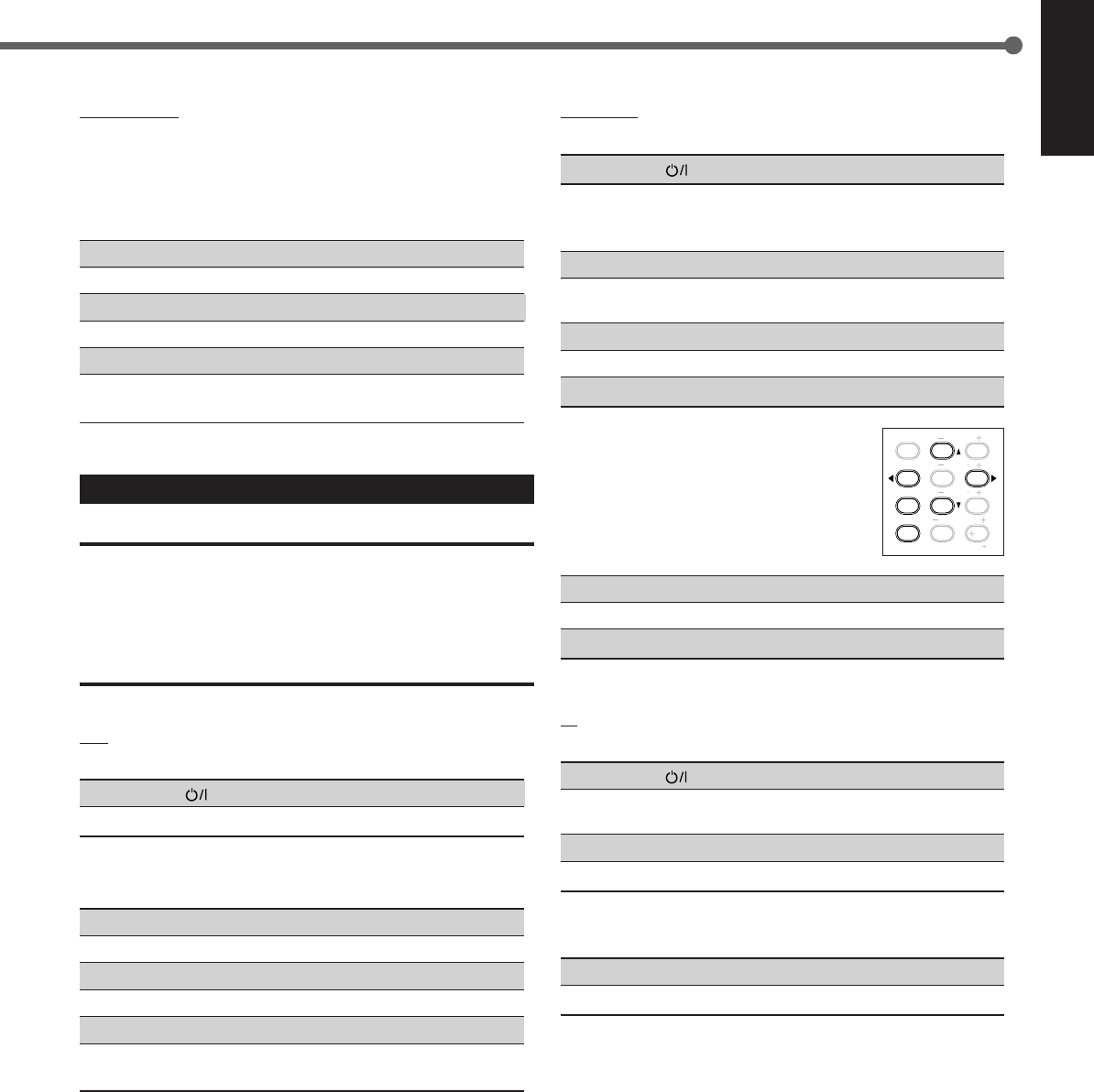
29
English
TEST
EFFECT
MENU
ENTER
CENTER
REAR L
SUBWOOFER
REAR R
1
4
7/P
10
2
5
8
0
3
6
9
10
100
RETURN
DVD player
You can always perform following operations:
STANDBY/ON DVD : Turn on or off a DVD player.
After pressing DVD or DVD MULTI, you can use following buttons
for DVD player operations:
33
33
3: Start playback.
4: Return to the beginning of the current
(or previous) track.
¢: Skip to the beginning of the next track.
77
77
7: Stop playback.
88
88
8: Pause playback. To release it, press 33
33
3.
DVD menu operations
After pressing DVD or DVD MULTI, you can
use following buttons for DVD menu
operations:
MENU : Display or erase the menu screen.
55
55
5/∞∞
∞∞
∞/33
33
3/22
22
2: Select an item on the menu screen.
ENTER : Enter a selected item.
TV
You can always perform following operations:
STANDBY/ON TV : Turn on or off a TV.
TV/VIDEO : Change the input mode (TV tuner and video
input).
TV VOLUME +/–: Adjust the volume.
TV CH +/–: Change the channels.
After pressing TV SOUND, you can use following buttons for TV
operations:
1 – 9, 0, 100+ (+10) :Select a channel.
RETURN (10) :Function as the RETURN button.
Cassette deck
Before starting operations described below, make sure that you have
changed the source name correctly. See page 8.
After pressing TAPE/CDR, you can use following buttons for
cassette deck operations:
33
33
3: Start playback.
FF : Fast wind the tape from left to right.
REW : Fast wind the tape from right to left.
77
77
7: Stop playback or recording.
88
88
8: Pause playback. To release it, press 33
33
3.
REC PAUSE : Press this button to enter recording pause.
Press this button and then 33
33
3 to start recording.
Operating Video Components
IMPORTANT:
To operate JVC’s video components using this remote control:
•Some JVC’s VCRs can accept two types of the control signals—
remote code “A” and “B.” Before using this remote control, make
sure that the remote control code of the VCR connected to the VCR
jacks is set to code “A.”
•Aim the remote control directly at the remote sensor on each
component, not on the receiver.
VCR
You can always perform following operations:
STANDBY/ON VCR :Turn on or off a VCR.
VCR CH +/–:Change the TV channels on the VCR.
After pressing VCR (source selecting button), you can use following
buttons for VCR operations:
33
33
3: Start playback.
FF : Fast wind a tape.
REW : Rewind a tape.
77
77
7: Stop playback or recording.
88
88
8: Pause playback. To release it, press 33
33
3.
REC PAUSE : Press this button to enter recording pause.
Press this button and then 33
33
3 to start recording.
EN24-32.RX-6020V[C]_f 02.1.8, 9:16 AM29
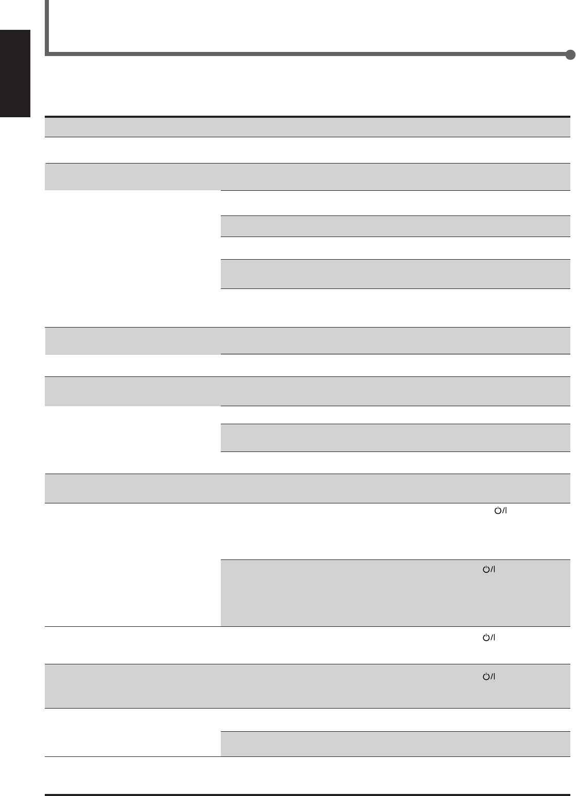
30
English
SOLUTION
Plug the power cord into an AC outlet.
Check speaker wiring and reconnect if
necessary.
Press SPEAKERS ON/OFF button correctly.
Select the correct source.
Press MUTING to cancel the mute.
Select the correct input mode (analog or
digital).
Check connections.
For analog connections, see page 6.
For digital connections, see page 7.
Check speaker wiring and reconnect if
necessary.
Adjust the balance properly (see page 15).
Connect an outdoor FM antenna or contact
your dealer.
Select a new station.
Check with your dealer to be sure you have the
correct antenna.
Check connections.
Move the antenna farther from automobile
traffic.
1. Press STANDBY/ON on the front
panel to turn off the receiver.
2. Stop the playback source.
3. Turn on the receiver again, and adjust the
volume.
Press STANDBY/ON on the front panel,
then check the speaker wiring.
If “OVERLOAD” does not disappear, unplug
the AC power cord, then plug it back again.
If speaker wiring is not short-circuited, contact
your dealer.
Press STANDBY/ON on the front panel to
turn off the receiver. After unplugging the
power cord, consult your dealer.
Press STANDBY/ON on the front panel to
turn off the receiver. After unplugging the
power cord, consult your dealer.
Remove the obstruction.
Replace batteries.
Select the correct remote control operation
mode (see pages 28 and 29).
POSSIBLE CAUSE
The power cord is not plugged in.
Speaker signal cables are not connected.
The SPEAKERS ON/OFF button is not
set correctly.
An incorrect source is selected.
Muting is activated.
An incorrect input mode (analog or
digital) is selected.
Connections are incorrect.
Speaker signal cables are not connected
properly.
The balance is set to one extreme.
Incoming signal is too weak.
The station is too far away.
An incorrect antenna is used.
Antennas are not connected properly.
Ignition noise from automobiles.
Speakers are overloaded because of high
volume.
Speakers are overloaded because of short
circuit of speaker terminals.
The built-in microcomputer is not
functioning correctly.
The receiver is overloaded because of a
high voltage.
There is an obstruction in front of the
remote sensor on the receiver.
Batteries are weak.
An incorrect remote control operation
mode is selected.
Troubleshooting
Use this chart to help you solving daily operational problems. If there is any problem you cannot solve, contact your JVC service center.
PROBLEM
The power does not turn on.
No sound from speakers.
Sound from one speaker only.
Continuous hiss or buzzing during FM
reception.
Occasional cracking noise during FM
reception.
“OVERLOAD” starts flashing on the
display.
“DSP MICON NG” starts flashing on the
display.
The STANDBY lamp lights up after
turning on the power, but soon the
receiver turns off (into standby mode).
Remote control does not work.
Remote control does not work for the
source (or other components) you try to
operate.
EN24-32.RX-6020V[C]_f 02.1.8, 9:16 AM30

31
English
Specifications Designs & specifications are subject to change without notice.
Amplifier
Output Power
At Stereo operation:
Front channels: 100 W per channel, min. RMS, driven into 8 Ω,
40 Hz to 20 kHz with no more than 0.8% total
harmonic distortion.
At Surround operation:
Front channels: 100 W per channel, min. RMS, driven into 8 Ω at 1 kHz with no
more than 0.8% total harmonic distortion.
Center channel: 100 W, min. RMS, driven into 8 Ω at 1 kHz, with no more than
0.8% total harmonic distortion.
Rear channels: 100 W per channel, min. RMS, driven into 8 Ω at 1 kHz, with no
more than 0.8% total harmonic distortion.
Audio
Audio Input Sensitivity/Impedance (1 kHz): DVD, VCR, TV SOUND, CD, TAPE/CDR:
220 mV/47 k Ω
Audio Input (DIGITAL IN)* : Coaxial: DIGITAL 1 (DVD): 0.5 V (p-p)/75 Ω
Optical: DIGITAL 2 (CD): –21 dBm to –15 dBm (660 nm ±30 nm)
* Corresponds to Linear PCM, Dolby Digital, and DTS Digital Surround
(with sampling frequency — 32 kHz, 44.1 kHz, 48 kHz).
Audio Output Level: TAPE/CDR, VCR: 220 mV
Signal-to-Noise Ratio (’66 IHF/’78 IHF): DVD, VCR, TV SOUND, CD, TAPE/CDR:
87 dB/78 dB
Frequency Response (8 Ω): DVD, VCR, TV SOUND, CD, TAPE/CDR:
20 Hz to 20 kHz (±1 dB)
Tone Control: Bass (100 Hz): ±10 dB
Treble (10 kHz): ±10 dB
Video
Video Input Sensitivity/Impedance:
Composite video: VCR, DVD: 1 V (p-p)/75 Ω
Video Output Level/Impedance:
Composite video: VCR, MONITOR OUT: 1 V (p-p)/75 Ω
Synchronization: Negative
Signal-to-Noise Ratio: 45 dB
EN24-32.RX-6020V[C]_f 02.1.8, 9:16 AM31

32
English
FM tuner (IHF)
Tuning Range: 87.5 MHz to 108.0 MHz
Usable Sensitivity: Monaural: 12.8 dBf (1.2 µV/75 Ω)
50 dB Quieting Sensitivity: Monaural: 21.3 dBf (3.2 µV/75 Ω)
Stereo: 41.3 dBf (31.5 µV/75 Ω)
Signal-to-Noise Ratio (IHF-A weighted): Monaural: 78 dB at 85 dBf
Stereo: 73 dB at 85 dBf
Total Harmonic Distortion: Monaural: 0.4% at 1 kHz
Stereo: 0.6% at 1 kHz
Stereo Separation at REC OUT: 35 dB at 1 kHz
Alternate Channel Selectivity: 45 dB: (±400 kHz)
Frequency Response: 30 Hz to 15 kHz: (+0.5 dB, –3 dB)
AM tuner
Tuning Range: 530 kHz to 1 710 kHz
Usable Sensitivity: Loop antenna 400 µV/m
Signal-to-Noise Ratio: 50 dB (100 mV/m)
General
Power Requirements: AC 120V , 60 Hz
Power Consumption: 180 W/230 VA (at operation)
2 W (in standby mode)
Dimensions (W x H x D): 435 mm x 146.5 mm x 416 mm
(17 3/16 in. x 5 13/16 in. x 16 7/16 in.)
Mass: 8.8 kg (19.5 lbs)
Specifications
EN24-32.RX-6020V[C]_f 02.1.8, 9:16 AM32

VICTOR COMPANY OF JAPAN, LIMITED
EN, FR 0102NHMMDWJEIN
J
V
C
RX-6020VBK[C]_COVER_f 02.1.8, 9:14 AM2

Caution: Proper Ventilation
To avoid risk of electric shock and fire and to protect from damage.
Locate the apparatus as follows:
Front: No obstructions open spacing.
Sides: No obstructions in 10 cm from the sides.
Top: No obstructions in 10 cm from the top.
Back: No obstructions in 15 cm from the back.
Bottom: No obstructions, place on the level surface.
In addition, maintain the best possible air circulation as illustrated.
Attention: Ventilation Correcte
Pour éviter les chocs électriques, l’incendie et tout autre dégât.
Disposer l’appareil en tenant compte des impératifs suivants
Avant: Rien ne doit gêner le dégagement
Flancs: Laisser 10 cm de dégagement latéral
Dessus: Laisser 10 cm de dégagement supérieur
Arrière: Laisser 15 cm de dégagement arrière
Dessous: Rien ne doit obstruer par dessous; poser l’appareil sur une
surface plate.
Veiller également à ce que l’air circule le mieux possible comme illustré.
Floor
Plancher
Stand height
15 cm or more
Hauteur du
socle: 15 cm ou
plus
Front
Avant
Spacing 15 cm or more
Dégagement de 15 cm ou plus
Wall or obstructions
Mur, ou obstruction
Caution –– STANDBY/ON button!
Disconnect the mains plug to shut the power off completely. The
STANDBY/ON button in any position does not disconnect
the mains line. The power can be remote controlled.
Attention –– Commutateur STANDBY/ON !
Déconnecter la fiche de secteur pour couper complètement le
courant. Le commutateur STANDBY/ON ne coupe jamais
complètement la ligne de secteur, quelle que soit sa position. Le
courant peut être télécommandé.
CAUTION
To reduce the risk of electrical shocks, fire, etc.:
1. Do not remove screws, covers or cabinet.
2. Do not expose this appliance to rain or moisture.
ATTENTION
Afin d’éviter tout risque d’électrocution, d’incendie, etc.:
1. Ne pas enlever les vis ni les panneaux et ne pas ouvrir le
coffret de l’appareil.
2. Ne pas exposer l’appareil à la pluie ni à l’humidité.
Warnings, Cautions and Others/
Mises en garde, précautions et indications diverses
RX-6020VBK
WARNING: TO REDUCE THE RISK OF FIRE
OR ELECTRIC SHOCK, DO NOT EXPOSE
THIS APPLIANCE TO RAIN OR MOISTURE.
CAUTION: TO REDUCE THE RISK OF ELECTRIC SHOCK.
DO NOT REMOVE COVER (OR BACK)
NO USER SERVICEABLE PARTS INSIDE.
REFER SERVICING TO QUALIFIED SERVICE PERSONNEL.
RISK OF ELECTRIC SHOCK
DO NOT OPEN
The lightning flash with arrowhead symbol,
within an equilateral triangle is intended to
alert the user to the presence of uninsulated
"dangerous voltage" within the product's
enclosure that may be of sufficient
magnitude to constitute a risk of electric
shock to persons.
The exclamation point within an equilateral
triangle is intended to alert the user to the
presence of important operating and
maintenance (servicing) instructions in the
literature accompanying the appliance.
CAUTION
For Canada/pour Le Canada
THIS DIGITAL APPARATUS DOES NOT EXCEED THE CLASS
B LIMITS FOR RADIO NOISE EMISSIONS FROM DIGITAL
APPARATUS AS SET OUT IN THE INTERFERENCE-CAUSING
EQUIPMENT STANDARD ENTITLED “DIGITAL APPARATUS,”
ICES-003 OF THE DEPARTMENT OF COMMUNICATIONS.
CET APPAREIL NUMERIQUE RESPECTE LES LIMITES DE
BRUITS RADIOELECTRIQUES APPLICABLES AUX
APPAREILS NUMERIQUES DE CLASSE B PRESCRITES
DANS LA NORME SUR LE MATERIEL BROUILLEUR;
“APPAREILS NUMERIQUES”, NMB-003 EDICTEE PAR LE
MINISTRE DES COMMUNICATIONS.
For U.S.A.
This equipment has been tested and found to comply with the limits
for a Class B digital device, pursuant to part 15 of the FCC Rules.
These limits are designed to provide reasonable protection against
harmful interference in a residential installation.
This equipment generates, uses and can radiate radio frequency
energy and, if not installed and used in accordance with the
instructions, may cause harmful interference to radio
communications. However, there is no guarantee that interference
will not occur in a particular installation. If this equipment does cause
harmful interference to radio or television reception, which can be
determined by turning the equipment off and on, the user is
encouraged to try to correct the interference by one or more of the
following measures:
Reorient or relocate the receiving antenna.
Increase the separation between the equipment and receiver.
Connect the equipment into an outlet on a circuit different from that
to which the receiver is connected.
Consult the dealer or an experienced radio/TV technician for help.
Changes or modifications not expressly approved by the
manufacturer for compliance could void the user’s authority to
operate the equipment.
For Canada/pour le Canada
CAUTION: TO PREVENT ELECTRIC SHOCK, MATCH WIDE
BLADE OF PLUG TO WIDE SLOT, FULLY INSERT
ATTENTION: POUR EVITER LES CHOCS ELECTRIQUES,
INTRODUIRE LA LAME LA PLUS LARGE DE LA FICHE DANS LA
BORNE CORRESPONDANTE DE LA PRISE ET POUSSER
JUSQUAU FOND
RX-6020VBK[J]_Safety_f 01.12.7, 11:32 AM1
1
Table of Contents
This mark indicates that the remote control CANNOT
be used for the operation explained. Use buttons on
the front panel.
This mark indicates that the remote control CAN
ONLY be used for the operation explained.
Table of Contents
Remote
NOT
Remote
ONLY
Parts Identification ...................................... 2
Getting Started........................................... 3
Before Installation ...................................................................... 3
Checking the Supplied Accessories ........................................... 3
Putting Batteries in the Remote Control .................................... 3
Connecting the FM and AM Antennas ....................................... 4
Connecting the Speakers ............................................................ 5
Connecting Audio/Video Components ....................................... 6
Connecting the Power Cord ....................................................... 7
Basic Operations ......................................... 8
Turning On the Power ................................................................ 8
Selecting the Source to Play ....................................................... 8
Adjusting the Volume ................................................................. 9
Listening Only with Headphones ............................................... 9
Turning Off the Sounds Temporarily—Muting ........................ 10
Changing the Display Brightness ............................................. 10
Turning Off the Power with the Sleep Timer ........................... 10
Basic Settings ........................................... 11
Setting the Digital Input (DIGITAL IN) Terminals ................. 11
Selecting the Analog or Digital Input Mode ............................ 11
Setting the Speaker Information ............................................... 12
Sound Adjustments.................................... 15
Attenuating the Input Signal .................................................... 15
Adjusting the Front Speakers Output Balance ......................... 15
Adjusting the Tone ................................................................... 15
Adjusting the Subwoofer Output Level.................................... 15
Tuner Operations ....................................... 16
Tuning in Stations .................................................................... 16
Using Preset Tuning ................................................................. 16
Selecting the FM Reception Mode ........................................... 17
Creating Realistic Sound Fields ................... 18
About Relations between Speaker Layout and
Surround Modes ................................................................. 20
Using Dolby Pro Logic II, Dolby Digital and
DTS Digital Surround ........................................................ 21
Using DAP Modes and All Channel Stereo ............................. 23
Using DVD MULTI Playback Mode ................ 24
Activating DVD MULTI Playback Mode ................................ 24
COMPU LINK Remote Control System ......... 25
AV COMPU LINK Remote Control System .... 26
Operating JVC's Audio/Video
Components .......................................... 28
Operating Audio Components .................................................. 28
Operating Video Components .................................................. 29
Troubleshooting ......................................... 30
Specifications ............................................ 31
EN01-07.RX-6020V[J]_f 01.12.7, 11:32 AM1
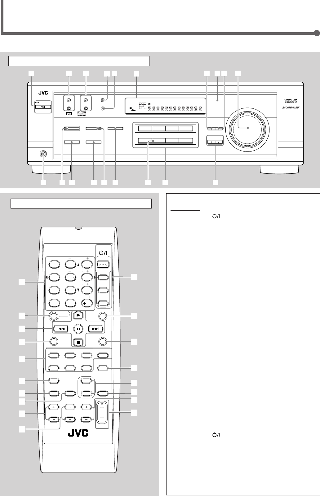
2
Parts Identification
Front Panel
See page(s) in the parentheses for details.
Remote Control Front Panel
1STANDBY/ON button and STANDBY lamp (8)
2FM/AM TUNING 5/∞ (up/down) buttons (16)
3FM/AM PRESET 5/∞ (up/down) buttons (16, 17)
4FM MODE button (17)
5MEMORY button (16, 17)
6Display (8)
7ADJUST button (15, 22, 23, 24)
8Remote sensor (3)
9SETTING button (11 – 14)
pMASTER VOLUME control (9)
qPHONES jack (9)
wSURROUND ON/OFF button (20 – 23)
eSURROUND MODE button (20 – 23)
rSPEAKERS ON/OFF button (9)
t•INPUT ANALOG button (11)
•INPUT ATT button (15)
yINPUT DIGITAL button (11, 12)
uSOURCE NAME button (9)
iSource selecting buttons (8, 9, 11, 16, 17, 24)
DVD MULTI, DVD, VCR, TV SOUND, CD, TAPE/CDR, FM, AM
oCONTROL UP5/DOWN∞ buttons (11 – 15, 22 – 24)
Remote Control
1• 10 keys for selecting preset channels (17)
•10 keys for adjusting sound (15, 22, 23, 24)
•10 keys for operating audio/video components (28, 29)
2SOUND button (15, 22 – 24)
3Operating buttons for audio/video components
(25, 28, 29)
4REC PAUSE button (28, 29)
5Source selecting buttons (8, 9, 11, 17, 24, 27 – 29)
TAPE/CDR, CD, DVD, DVD MULTI, FM/AM, TV SOUND, VCR
6FM MODE button (17)
7DIMMER button (10)
8TV/VIDEO button (29)
9VCR CH (channel) +/– buttons (29)
pTV CH (channel) +/– buttons (29)
qSTANDBY/ON buttons (8, 26, 29)
AUDIO, TV, VCR, DVD
wSLEEP button (10)
eCD–DISC button (28)
rANALOG/DIGITAL button (12)
tSURROUND ON/OFF and SURROUND MODE buttons
(20, 21, 23, 28)
yMUTING button (10)
uTV VOLUME +/– buttons (29)
iVOLUME +/– button (9)
FM MODE
A/V CONTROL
RECEIVER
AUDIO
TV
VCR
DVD
TEST
EFFECT
MENU
ENTER
RETURN
SOUND
SLEEP
CENTER
REAR L
SUBWOOFER
CD–DISC
REC PAUSE
TAPE/CDR CD DVD DVD MULTI
FM/AM
FM MODE
DIMMER TV/VIDEO
SURROUND
ON/OFF
MODE
MUTING
VCR CH TV CH
VOLUME
TV SOUND VCR ANALOG
/DIGITAL
REAR R
100
1
4
7/P
10
2
5
8
0
3
6
9
10
REMOTE CONTROL RM-SRX6020J
REW FF
TV VOLUME
STANDBY/ON
6
7
3
t
u
y
5
4
9
p
i
r
q
8
2
1
e
w
DVDDVD MULTI VCR TV SOUND
ADJUST
RX-6020V
AUDIO/VIDEO CONTROL RECEIVER
SETTING
MASTER VOLUME
CONTROL
DOWN UP
CD TAPE/CDR
SOURCE NAME
INPUT DIGITALINPUT ANALOG
SPEAKERS ON/OFF
SURROUND MODE
PHONES
SURROUND ON/OFF
FM/AM TUNING
STANDBY
FM/AM PRESET FM MODE
MEMORY
INPUT ATT
FM AM
DIGITAL
SURROUND
25
48
7
3
STANDBY/ON
wo
y
t
r
e
q
19p
i
u
6
LC
S.WFR
LS RS
CH-
S
LFE
SPK
PRO LOGIC ΙΙ DSP H.PHONE
AUTO MUTING
TUNED STEREO
VOLUME
INPUT ATT
SLEEP
DIGITAL AUTO
ANALOG
DIGITAL
LINEAR PCM
R
EN01-07.RX-6020V[J]_f 01.12.7, 11:32 AM2
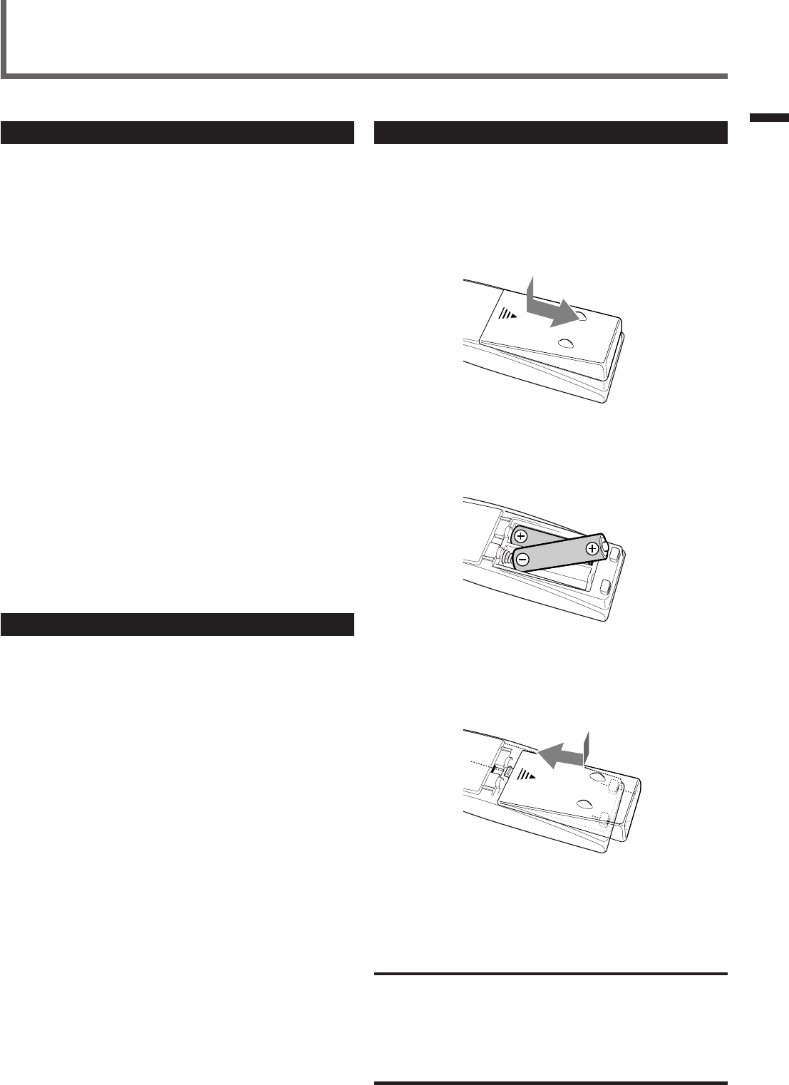
3
Parts Identification / Getting Started
Putting Batteries in the Remote Control
Before using the remote control, put two supplied batteries first.
•When using the remote control, aim the remote control directly at
the remote sensor on the unit.
1
On the back of the remote control, remove the
battery cover.
2
Insert batteries.
•Make sure to match the polarity: (+) to (+) and (–) to (–).
3
Replace the cover.
If the range or effectiveness of the remote control decreases, replace
the batteries. Use two R6P(SUM-3)/AA(15F) type dry-cell batteries.
CAUTION:
Follow these precautions to avoid leaking or cracking cells:
•Place batteries in the remote control so they match the polarity:
(+) to (+) and (–) to (–).
•Use the correct type of batteries. Batteries that look similar may
differ in voltage.
•Always replace both batteries at the same time.
•Do not expose batteries to heat or flame.
Getting Started
Before Installation
General Precautions
•DO NOT insert any metal object to the unit.
•DO NOT disassemble the unit or remove screws, covers, or
cabinet.
•DO NOT expose the unit to rain or moisture.
Locations
•Install the unit in a location that is level and protected from
moisture.
•The temperature around the unit must be between –5˚C and 35˚C
(23˚F and 95˚F).
•Make sure there is good ventilation around the unit. Poor
ventilation could cause overheating and damage the unit.
Handling the unit
•DO NOT touch the power cord with wet hands.
•DO NOT pull the power cord to unplug the cord. When
unplugging the cord, always grasp the plug so as not to damage
the cord.
•Keep the power cord away from the connecting cords and the
antenna. The power cord may cause noise or screen interference. It
is recommended to use a coaxial cable for antenna connection,
since it is well-shielded against interference.
•When a power failure occurs, or when you unplug the power cord,
the preset settings such as preset FM/AM channels and sound
adjustments may be erased in a few days.
Checking the Supplied Accessories
Check to be sure you have all of the following supplied accessories.
The number in the parentheses indicates the quantity of the piece(s)
supplied.
• Remote Control (1)
• Batteries (2)
• AM Loop Antenna (1)
• FM Antenna (1)
If anything is missing, contact your dealer immediately.
EN01-07.RX-6020V[J]_f 01.12.7, 11:32 AM3
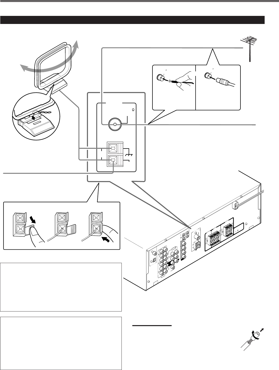
4
Getting Started
AM loop antenna connection
Connect the AM loop antenna supplied to the AM LOOP
terminals.
Turn the loop until you have the best reception.
•If the reception is poor, connect an outdoor single vinyl-
covered wire (not supplied) to the AM EXT terminal. (Keep
the AM loop antenna connected.)
FM antenna connection
Connect the supplied FM antenna to the FM 75 Ω COAXIAL
terminal as temporary measure.
Extend the supplied FM antenna horizontally.
•If the reception is poor, connect an outdoor FM antenna (not
supplied). Before attaching a 75 Ω coaxial cable (with a
standard type connector), disconnect the supplied FM
antenna.
Connecting the FM and AM Antennas
CENTER
RIGHT
816
DVD
DIGITAL 1
(DVD)
DIGITAL 2 ( CD )
CD
DVD
FM 75
COAXIAL
COMPU LINK-4
(SYNCHRO)
ANTENNA
TV SOUND
AUDIO
VIDEO
AUDIO
OUT
(REC)
RIGHT LEFT
AM
LOOP
AM
EXIT
RIGHT LEFT
TAPE
/CDR
IN
(PLAY)
OUT
(REC) OUT
(REC)
VCR
IN
(PLAY)
VCR
IN
(PLAY)
DIGITAL IN
SUB
WOOFER
CENTER
SPEAKER
REAR
SPEAKERS
RIGHT LEFT
FRONT
SPEAKERS
LEFT
CAUTION :
SPEAKER IMPEDANCE
+
–
+
–
+
–
+
–
AV
COMPU LINK
RIGHT LEFT
REAR
MONITOR
OUT
FRONT
123
AM
LOOP
FM 75
COAXIAL
AM
EXT
ANTENNA
FM 75
COAXIAL
FM 75
COAXIAL
SUBWOOFER
OUT
AM Loop Antenna
(supplied)
or
If AM reception is poor, connect outdoor
single vinyl-covered wire (not supplied).
Extend the supplied FM antenna horizontally.
FM antenna (supplied)
Outdoor FM antenna (not supplied)
If FM reception is poor, connect outdoor FM
antenna.
Supplied FM
antenna
Standard type
outdoor FM antenna
(not supplied)
Snap the tabs on the loop
into the slots of the base
to assemble the AM loop
antenna.
Notes:
•If the AM loop antenna wire is covered with vinyl,
remove the vinyl while twisting it as shown to the right.
•Make sure antenna conductors do not touch any other
terminals, connecting cords and the power cord. This
could cause poor reception.
EN01-07.RX-6020V[J]_f 01.12.7, 11:32 AM4
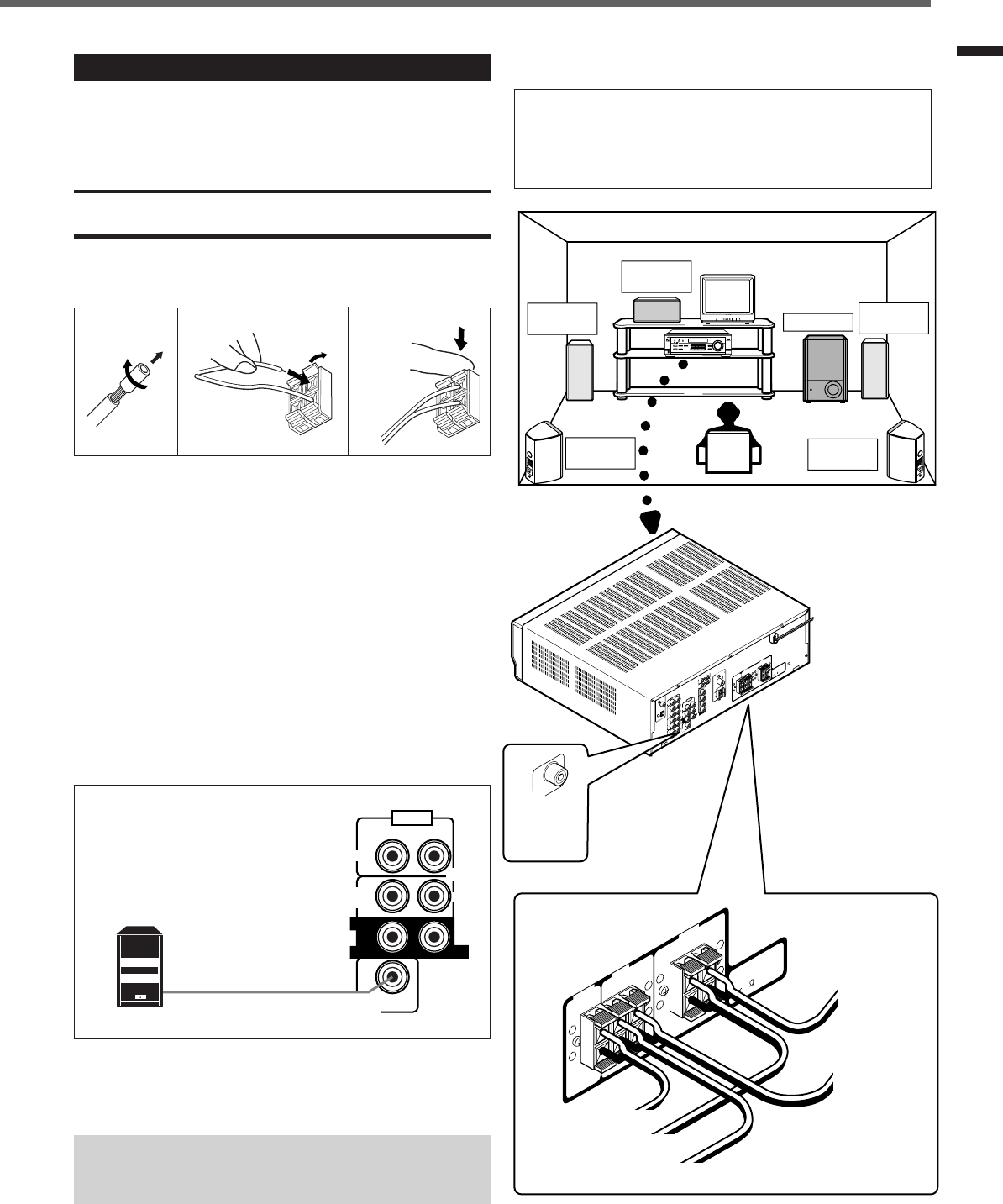
5
SUBWOOFER
OUT
AUDIO
CENTER
FRONT
DVD
SUB
WOOFER
RIGHT LEFT
RIGHT
REAR
LEFT
Powered subwoofer
Getting Started
Connecting the Speakers
After connecting the front, center, rear speakers and/or a subwoofer,
set the speaker setting information properly to obtain the best
possible surround effect. For details, see pages 12 to 14.
CAUTION:
Use speakers with the SPEAKER IMPEDANCE indicated by the
speaker terminals.
Connecting the front, center and rear speakers
For each speaker, connect the (+) and (–) terminals on the rear panel
to the (+) and (–) terminals marked on the speakers.
1
Cut, twist and remove the insulation at the end of
each speaker cord.
2
Open the terminal (1), then insert the speaker
cord (2).
3
Close the terminal.
Connecting the subwoofer speaker
By connecting a powered subwoofer, you can enhance the bass or
reproduce the original LFE signals recorded in the digital software.
Connect the input jack of a powered subwoofer to the
SUBWOOFER OUT jack on the rear panel, using a cable with RCA
pin plugs (not supplied).
• Refer also to the manual supplied with your subwoofer.
Since bass sound is non-directional, you can place a powered
subwoofer wherever you like. Normally place it in front of
you.
123
1
2
Speaker layout diagram
“NO” for the subwoofer, “LARGE” for the front speakers,
and “SMALL” for the center and rear speakers are initial
settings. To get best possible sound, change the subwoofer
and speaker settings to fit your listening conditions (See
pages 12 and 13).
Right rear
speaker
DIGITAL 1
(DVD)
DIGITAL 2 ( CD )
CD
FM 75
COAXIAL
ANTENNA
TV SOUND
AUDIO
OUT
(REC)
AM
LOOP
AM
EXIT
RIGHT LEFT
TAPE
/CDR
IN
(PLAY)
OUT
(REC)
VCR
IN
(PLAY)
DIGITAL IN
CENTER
SPEAKER
REAR
SPEAKERS
RIGHT LEFT
FRONT
SPEAKERS
RIGHT LEFT
CAUTION :
SPEAKER IMPEDANCE
816
+
–
+
–
+
–
+
–
CENTER
SPEAKER
REAR
SPEAKERS
RIGHT LEFT
FRONT
SPEAKERS
RIGHT LEFT
CAUTION :
SPEAKER IMPEDANCE
816
+
–
+
–
+
–
+
–
Left front
speaker Subwoofer
Center
speaker
Left rear
speaker
Right front
speaker
To
subwoofer
SUBWOOFER
OUT
DVD
COMPU LINK-4
(SYNCHRO)
VIDEO
OUT
(REC)
VCR
IN
(PLAY)
MONITOR
OUT
DVD
FRONT
SUBWOOFER
OUT
AUDIO
RIGHT LEFT
SUB
WOOFER
RIGHT LEFT
REAR
CENTER
DVD VCR TV SOUND
ADJUST
RX-6020V AUDIO/VIDEO CONTROL RECEIVER
SETTING
MASTER VOLUME
CONTROL
DOWN UP
CD TAPE/CDR
SOURCE NAME
INPUT DIGITALINPUT ANALOG
SPEAKERS ON/OFF
SURROUND MODE
PHONES
SURROUND ON/OFF
FM/AM TUNING
STANDBY
FM/AM PRESET FM MODE
MEMORY
INPUT ATT
AM
DIGITAL
SURROUND
STANDBY/ON
DVD MULTI
FM
To left
front speaker
To left
rear speaker
To right front speaker
To right rear speaker
AV
COMPU LINK
To center speaker
EN01-07.RX-6020V[J]_f 01.12.11, 11:55 AM5
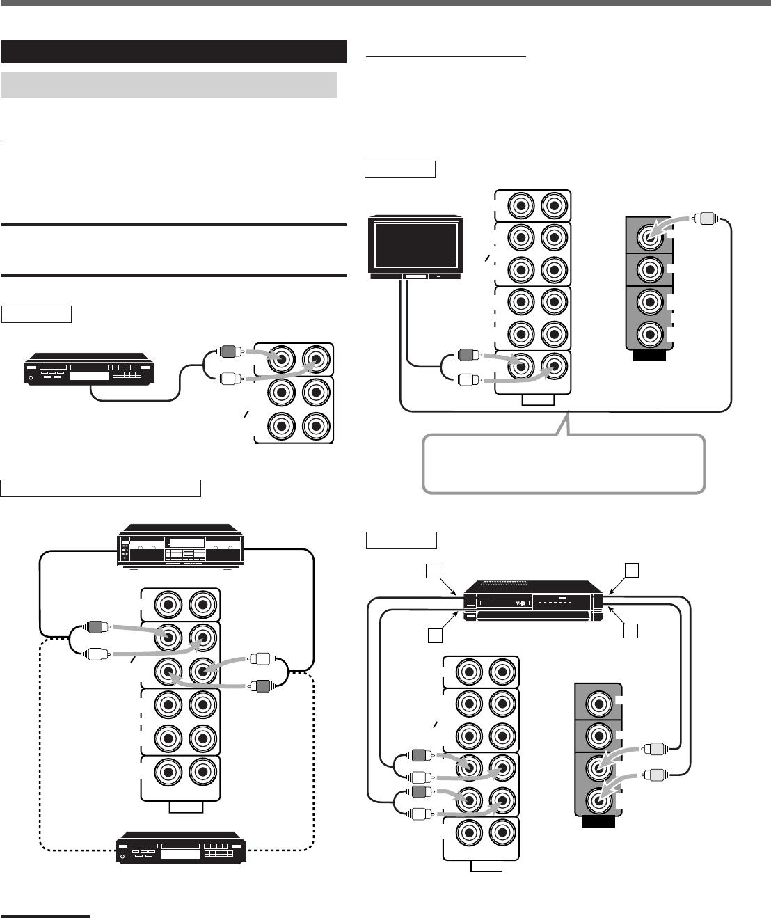
6
VIDEO
VCR
OUT
(REC)
IN
(PLAY)
MONITOR
OUT
DVD
IN
(PLAY)
CD
OUT
(REC)
AUDIO
RIGHT LEFT
TV SOUND
OUT
(REC)
VCR
TAPE
CDR
IN
(PLAY)
CD
PHONO
AUDIO
TV SOUND
IN
(PLAY)
CD
IN
(PLAY)
RIGHT LEFT
TAPE
CDR
OUT
(REC)
VCR
OUT
(REC)
Getting Started
Video component connections
Use the cables with RCA pin plugs (not supplied).
Connect the white plug to the audio left jack, the red plug to the
audio right jack, and the yellow plug to the video jack.
Connecting Audio/Video Components
Turn off all components before connecting.
Analog connections
Audio component connections
Use the cables with RCA pin plugs (not supplied).
Connect the white plug to the audio left jack, and the red plug to the
audio right jack.
CAUTION:
If you connect a sound-enhancing device such as a graphic equalizer
between the source components and this receiver, the sound output
through this receiver may be distorted.
To audio output
CD player
Cassette deck or CD recorder
To audio output
CD recorder
To audio outputTo audio input
TAPE
CDR
CD
OUT
(REC)
IN
(PLAY)
Note:
You can connect either a cassette deck or a CD recorder to the TAPE/
CDR jacks. When connecting a CD recorder to the TAPE/CDR jacks,
change the source name to “CDR”, which will be shown on the display
when selected as the source. See page 9 for details.
If your audio components have a COMPU LINK jack
See also page 25 for detailed information about the connection and
the COMPU LINK remote control system.
TV
To audio
output
Connect the TV to the MONITOR OUT jack to view
the playback picture from the other connected video
components.
To video input
TV
VCR
ÅTo left/right channel audio output
ıTo left/right channel audio input
ÇTo video output
ÎTo video input
VCR
A
VIDEO
TV SOUND
VCR
OUT
(REC) OUT
(REC)
IN
(PLAY) IN
(PLAY)
TAPE
CDR
CD
OUT
(REC)
IN
(PLAY)
MONITOR
OUT
RIGHT LEFT
DVD
AUDIO
C
D
B
VCR
CD player
Cassette deck
To audio input
EN01-07.RX-6020V[J]_f 01.12.7, 11:32 AM6
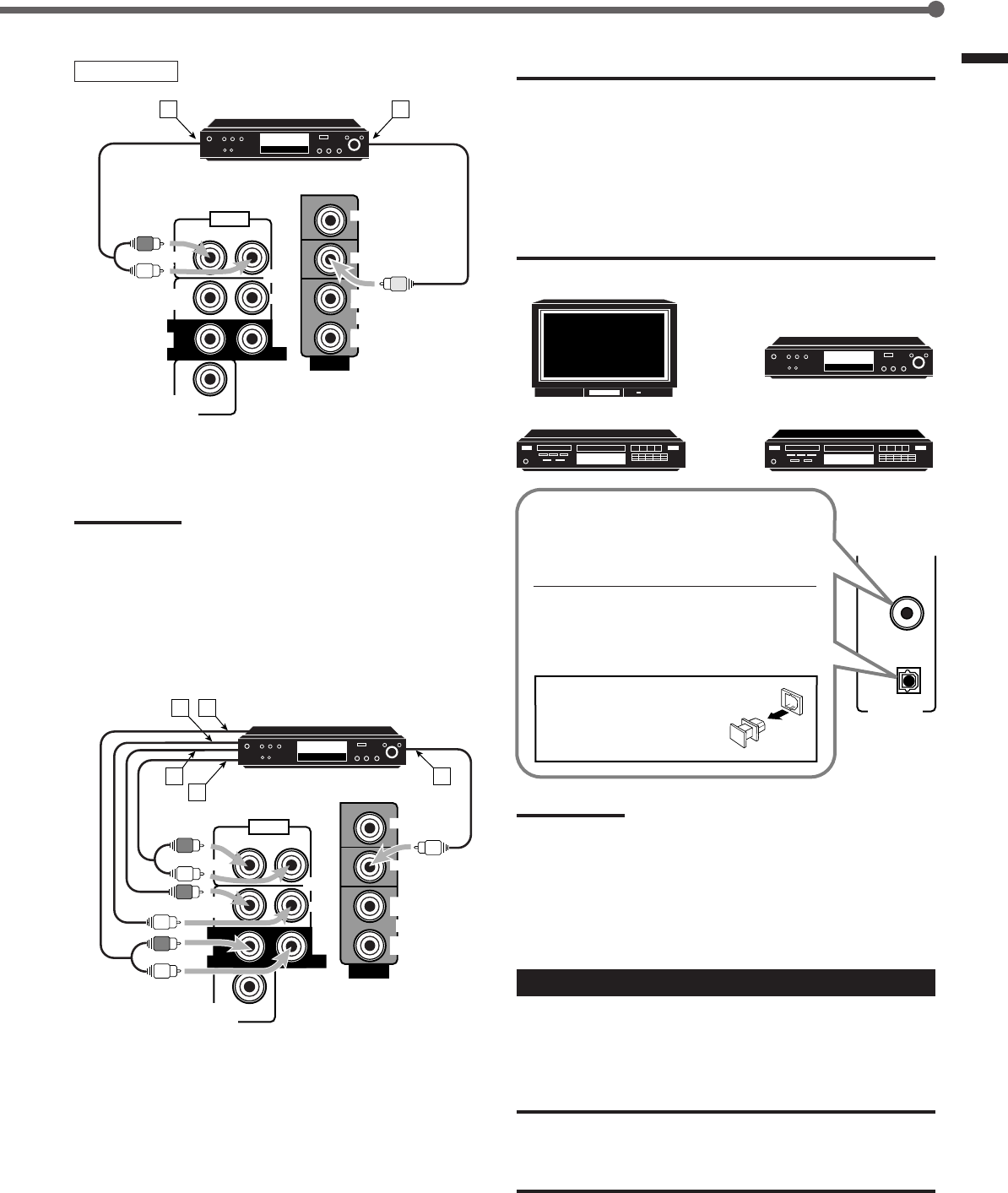
7
Getting Started
DVD player IMPORTANT:
• When connecting the DVD player or digital TV to the digital terminal,
you also need to connect it to the video jack on the rear. Without
connecting it to the video jack, you cannot view any playback
picture.
• After connecting the components to the DIGITAL IN terminals, make
sure the following if necessary:
– Set the digital input terminal setting correctly. For details, see
“Setting the Digital Input (DIGITAL IN) Terminals” on page 11.
– Select the digital input mode correctly. For details, see “Selecting
the Analog or Digital Input Mode” on page 11.
Notes:
•When shipped from the factory, the DIGITAL IN terminals have
been set for use with the following components:
–DIGITAL 1 (coaxial): For DVD player
–DIGITAL 2 (optical): For CD player
•When you want to operate the CD player or CD recorder using the
COMPU LINK remote control system, connect the target
component also as described in “Analog connections” (see page 6).
Connecting the Power Cord
Before plugging the power cord into an AC outlet, make sure that all
connections have been made.
Plug the power cord into an AC outlet.
CAUTIONS:
•Do not touch the power cord with wet hands.
•Do not pull on the power cord to unplug the cord. When
unplugging the cord, always grasp the plug so as not to damage
the cord.
DVD player
ÅTo front left/right channel audio output (or to audio mixed
output)
ıTo video output
Note:
To enjoy the software encoded with Dolby Digital or DTS Digital
Surround, you must connect the DVD player using the digital terminal
on the rear of this receiver. (See “Digital connections” below.)
SUBWOOFER
OUT
AUDIO
CENTER
FRONT
DVD
SUB
WOOFER
RIGHT LEFT
RIGHT
REAR
LEFT
VIDEO
VCR
OUT
(REC)
IN
(PLAY)
MONITOR
OUT
DVD
DVD
AB
Digital connections
This receiver is equipped with two DIGITAL IN terminals—one
digital coaxial terminal and one digital optical terminal.
You can connect any component to one of the digital terminals using
a digital coaxial cable (not supplied) or digital optical cable (not
supplied).
ÅTo rear left/right channel audio output
ıTo center channel audio output
ÇTo subwoofer audio output
ÎTo front left/right channel audio output
‰To video output
For enjoying DVD MULTI Playback Mode—
• When you connect the DVD player with its analog discrete output
(5.1 CH reproduction) jacks:
DVD player
SUBWOOFER
OUT
AUDIO
CENTER
FRONT
DVD
SUB
WOOFER
RIGHT LEFT
RIGHT
REAR
LEFT
VIDEO
VCR
OUT
(REC)
IN
(PLAY)
MONITOR
OUT
DVD
DVD
BA
E
C
D
DVD
DIGITAL 1
(DVD)
DIGITAL IN
DIGITAL 2 ( CD )
DVD player
Digital TV
CD player CD recorder
When the component has a digital coaxial
output terminal, connect it to the DIGITAL
1 (DVD) terminal, with the digital coaxial
cable (not supplied).
When the component has a digital optical
output terminal, connect it to the DIGITAL
2 (CD) terminal, with the digital optical
cable (not supplied).
Before connecting a digital
optical cable, unplug the
protective plug.
EN01-07.RX-6020V[J]_f 01.12.7, 2:26 PM7
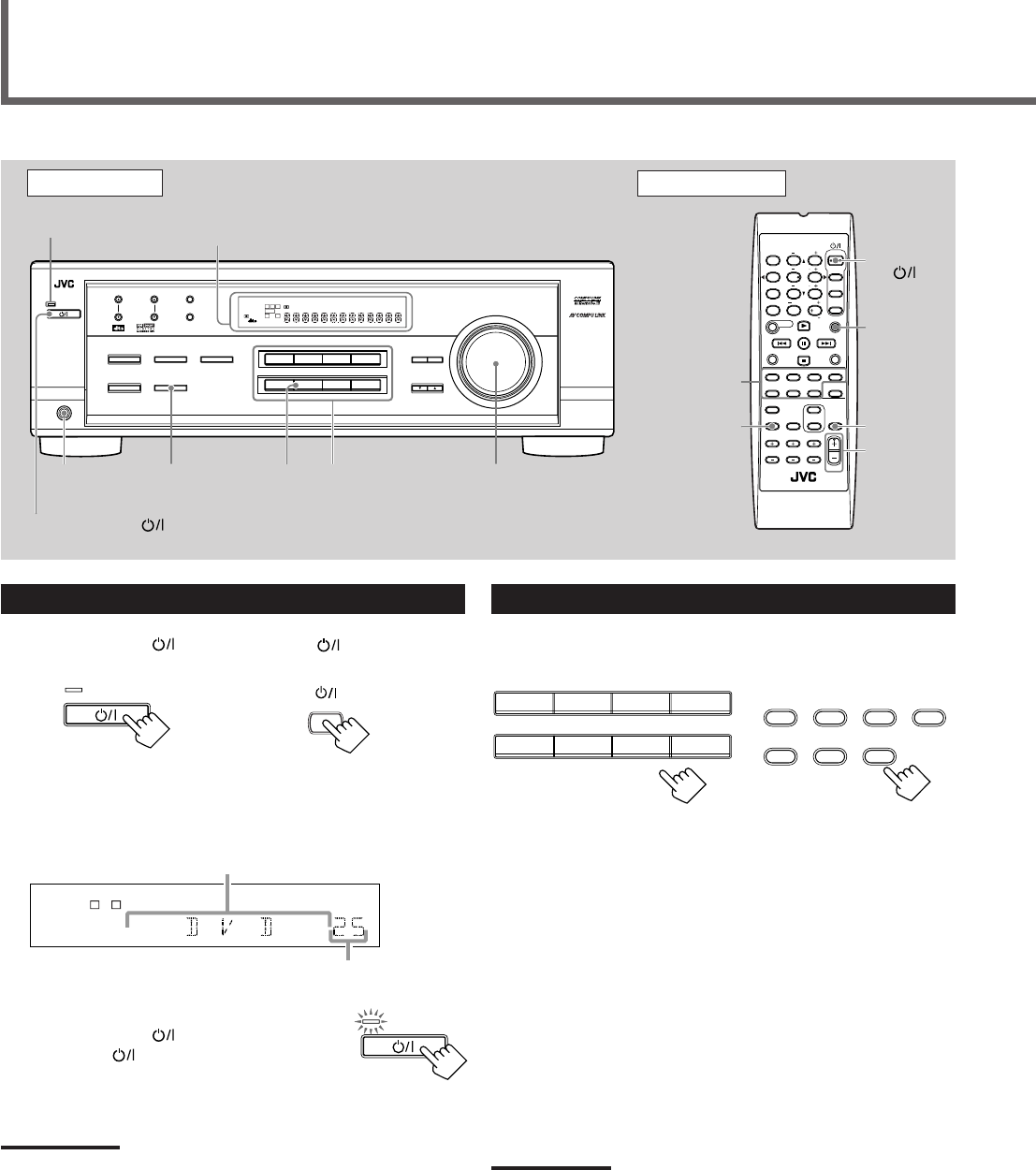
8
Turning On the Power
Press STANDBY/ON (or STANDBY/ON AUDIO on the
remote control).
The STANDBY lamp goes off. The name of the current source (or
station frequency) appears on the display.
To turn off the power (into standby mode)
Press STANDBY/ON (or
STANDBY/ON AUDIO on the remote control)
again.
The STANDBY lamp lights up.
NOTE:
A small amount of power is consumed in standby mode. To turn the
power off completely, unplug the AC power cord.
Front Panel Remote Control
MUTING
SLEEP
Source
selecting
buttons
VOLUME
+/–
STANDBY/
ON
AUDIO
Basic Operations
MASTER
VOLUME
DisplaySTANDBY lamp
On the front panel
AUDIO
STANDBY/ON
Source
selecting
buttons
FM MODE
A/V CONTROL
RECEIVER
AUDIO
TV
VCR
DVD
TEST
EFFECT
MENU
ENTER
RETURN
SOUND
SLEEP
CENTER
REAR L
SUBWOOFER
CD–DISC
REC PAUSE
TAPE/CDR CD DVD DVD MULTI
FM/AM
FM MODE
DIMMER TV/VIDEO
SURROUND
ON/OFF
MODE
MUTING
VCR CH TV CH
VOLUME
TV SOUND VCR ANALOG
/DIGITAL
REAR R
100
1
4
7/P
10
2
5
8
0
3
6
9
10
REMOTE CONTROL RM-SRX6020J
REW FF
TV VOLUME
STANDBY/ON
STANDBY/ON
SPEAKERS
ON/OFF
PHONES
jack
DVDDVD MULTI VCR TV SOUND
ADJUST
RX-6020V
AUDIO/VIDEO CONTROL RECEIVER
SETTING
MASTER VOLUME
CONTROL
DOWN UP
CD TAPE/CDR
SOURCE NAME
INPUT DIGITALINPUT ANALOG
SPEAKERS ON/OFF
SURROUND MODE
PHONES
SURROUND ON/OFF
FM/AM TUNING
STANDBY
FM/AM PRESET FM MODE
MEMORY
INPUT ATT
FM AM
DIGITAL
SURROUND
STANDBY/ON
LC
S.WFR
LS RS
CH-
S
LFE
SPK
PRO LOGIC ΙΙ DSP H.PHONE
AUTO MUTING
TUNED STEREO
VOLUME
INPUT ATT
SLEEP
DIGITAL AUTO
ANALOG
DIGITAL
LINEAR PCM
R
SOURCE
NAME
LC
S.WFR
LS RS
CH-
S
LFE
SPK
VOLUME
ANALOG
R
Current volume level is shown here
Current source name appears
STANDBY
STANDBY/ON
DVDDVD MULTI VCR TV SOUND
CD TAPE/CDR
SOURCE NAME
FM AM
TAPE/CDR CD DVD DVD MULTI
FM/AM TV SOUND VCR
Selecting the Source to Play
Press one of the source selecting buttons.
The selected source name appears on the display.
On the front panel From the remote control
DVD MULTI : Select the DVD player for viewing the digital video
disc using the analog discrete output mode (5.1 ch
reproduction).
To enjoy the DVD MULTI playback, see page 24.
DVD : Select the DVD player.
VCR : Select the VCR.
TV SOUND : Select the TV sound.
CD * : Select the CD player.
TAPE/CDR * : Select the cassette deck (or the CD recorder).
FM and AM (FM/AM) *
: Select an FM or AM broadcast.
•Each time you press FM/AM on the remote
control, the band alternates between FM and AM.
Notes:
•When connecting a CD recorder (to the TAPE/CDR jacks), change
the source name that appears on the display. See page 9 for
details.
•When you have connected some digital source components using
digital terminals (see page 7), you need to select the digital input
mode (see page 11).
•When you press one of the source selecting buttons on the remote
control marked above with an asterisk (
*
), the receiver
automatically turns on.
From the remote control
DIMMER
STANDBY/ON
STANDBY
EN08-17.RX-6020V[J]_f 01.12.7, 11:32 AM8
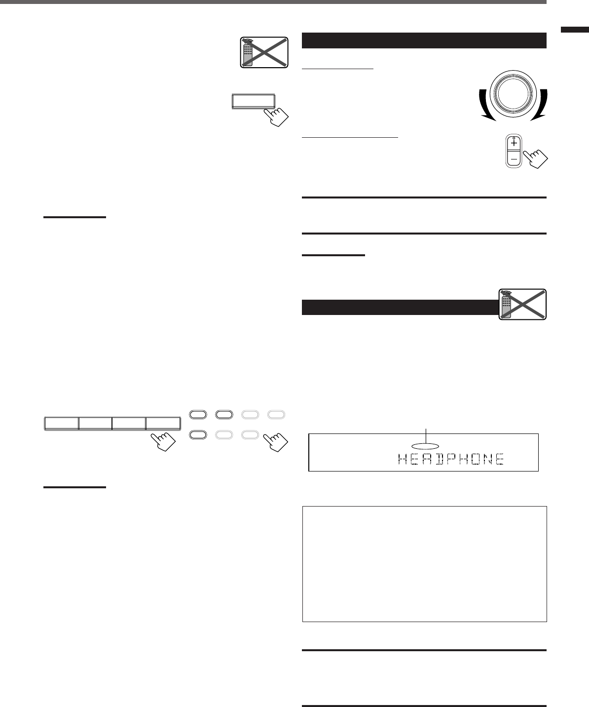
9
Basic Operations
Changing the source name
When you connect the CD recorder to the
TAPE/CDR jacks on the rear panel, change the
source name shown on the display.
1
Press TAPE/CDR (SOURCE NAME).
• Make sure “TAPE” appears on the display.
2
Press and hold SOURCE NAME (TAPE/CDR)
until “ASSIGN CDR” appears on the display.
To change the source name from “CDR” to “TAPE,” repeat the
same procedure above (in step
1
, make sure “CDR” appears on the
display).
Note:
Without changing the source name, you can still use the connected
component. However, there may be some inconvenience:
– “TAPE” will appear on the display when you select the CD
recorder.
– You cannot use the digital input (see page 11) for the CD recorder.
– You cannot use the COMPU LINK remote control system (see page
25) to operate the CD recorder.
Selecting different sources for each picture and
sound
You can watch picture from a video component while listening to
sound from another component.
Press one of the audio source selecting buttons—CD, TAPE/CDR,
FM, AM (FM/AM), while viewing the picture from a video
component such as the VCR or DVD player, etc.
On the front panel From the remote control
Note:
Once you have selected a video source, pictures of the selected
source are sent to the TV until you select another video source.
SOURCE NAME
TAPE/CDR
Remote
NOT
Adjusting the Volume
On the front panel:
To increase the volume, turn MASTER
VOLUME clockwise.
To decrease the volume, turn it
counterclockwise.
From the remote control:
To increase the volume, press VOLUME +.
To decrease the volume, press VOLUME –.
CAUTION:
Always set the volume to the minimum before starting any source. If
the volume is set at its high level, the sudden blast of sound energy
can permanently damage your hearing and/or ruin your speakers.
Note:
The volume level can be adjusted within the range from “0” (minimum)
to “50” (maximum).
Listening Only with Headphones
You must turn off speakers when you listen with headphones.
1
Connect a pair of headphones to the PHONES jack on the front
panel.
2
Press SPEAKERS ON/OFF.
•“HEADPHONE” appears for a while and the H. PHONE
indicator lights up on the display.
This cancels the Surround mode currently selected, and activates
the HEADPHONE mode (see below).
HEADPHONE mode:
When using the headphones, following signals are output
regardless of your speaker setting:
— For 2 channel sources, the front left and right channel signals
are output directly from the headphones.
— For multichannel sources, the front left, right, center, and rear
channel signals are down-mixed and then output from the
headphones.
You can enjoy multichannel sound sources using the
headphones.
CAUTION:
Be sure to turn down the volume:
•Before connecting or putting on headphones, as high volume can
damage both headphones and your hearing.
•Before turning on speakers again, as high volume may output from
the speakers.
MASTER VOLUME
VOLUME
Remote
NOT
L
H.PHONE
ANALOG
R
The H. PHONE indicator lights up.
CD TAPE/CDR
SOURCE NAME
FM AM
TAPE/CDR CD DVD DVD MULTI
FM/AM TV SOUND VCR
EN08-17.RX-6020V[J]_f 01.12.7, 4:17 PM9
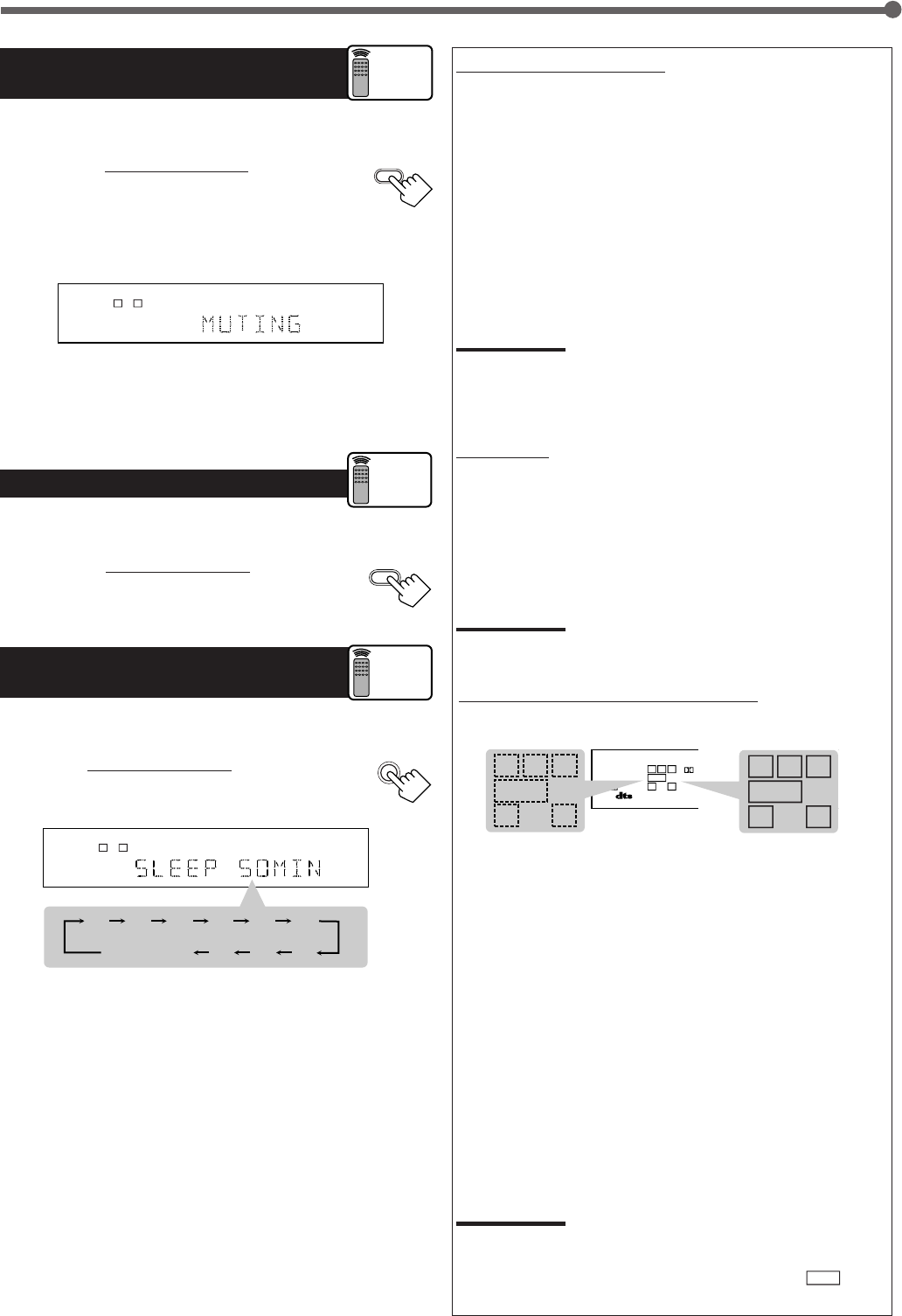
10
Turning Off the Sounds
Temporarily—Muting
You can mute the sound temporarily.
Press MUTING on the remote control to mute
the sound through all speakers or headphones
connected.
• “MUTING” appears on the display and the volume
turns off (the volume level indicator goes off).
To restore the sound, press MUTING again.
• Turning MASTER VOLUME on the front panel or pressing
VOLUME +/– on the remote control also restores the sound.
Changing the Display Brightness
You can dim the display.
Press DIMMER on the remote control .
• Each time you press the button, the display dims and
brightens alternately.
Turning Off the Power
with the Sleep Timer
You can fall asleep while listening to music—Sleep Timer.
Press SLEEP on the remote control repeatedly.
• The SLEEP indicator lights up on the display, and the
shut-off time changes in 10 minutes intervals.
When the shut-off time comes
The receiver turns off automatically.
To check or change the time remaining before the shut-off time
Press SLEEP once.
The remaining time (in minutes) until the shut-off time appears.
• To change the shut-off time, press SLEEP repeatedly until
preferred remaining time appears on the display.
To cancel the Sleep Timer
Press SLEEP repeatedly until “SLEEP 0 MIN” appears on the
display. (The SLEEP indicator goes off.)
• Turning off the power also cancels the Sleep Timer.
Basic Operations
LC
S.WFR
LS RS
CH-
S
LFE
SPK
ANALOG
R
MUTING
DIMMER
Remote
ONLY
SLEEP
2010 30 40 50 60
70
8090
(Canceled)
0
LC
S.WFR
LS RS
CH-
S
LFE
SPK SLEEP
ANALOG
R
Remote
ONLY
Basic adjustment auto memory
This receiver memorizes sound settings for each source when:
•Turning off the power,
•Changing the source, and
•Assigning the source name.
When you change the source, the memorized settings for the newly
selected source are automatically recalled.
Following can be stored for each source:
•Input attenuator mode (see page 15)
•Balance (see page 15)
•Tone adjustment (see page 15)
•Subwoofer output level (see page 15)
•Surround mode selection (see page 21-23)
Notes:
• You cannot assign and store different settings for digital input mode
and analog input mode.
• If the source is FM or AM, you can assign a different setting for
each band.
For recording
You can record any source playing through the receiver to a cassette
deck (or a CD recorder) connected to the TAPE/CDR jacks and the
VCR connected to the VCR jacks at the same time.
While recording, you can listen to the selected sound source at
whatever sound level you like without affecting the sound levels of
the recording.
Note:
The output level, tone adjustment (see page 15), and Surround
modes (see page 21-23) cannot affect the recording.
Signal and speaker indicators on the display
Signal indicators Speaker indicators
The following signal indicators light up—:
L:•When digital input is selected: Lights up when the left
channel signal comes in.
•When analog input is selected: Always lights up.
R:•When digital input is selected: Lights up when the right
channel signal comes in.
•When analog input is selected: Always lights up.
C:When the center channel signal comes in.
LS : When the left rear channel signal comes in.
RS : When the right rear channel signal comes in.
S:When the monaural rear channel signal or 2 ch Dolby
Surround encoded signal comes in.
LFE: When the LFE channel signal comes in.
The speaker indicators light up when both of the following
conditions are satisfied:
•The corresponding speaker is activated, and
•The corresponding speaker is required for the current playback.
Notes:
•When you select “DVD MULTI,” all signal indicators except “S” light
up.
•When “SUBWOOFER” is set to “YES” (see page 12),
S.WFR
lights
up.
Remote
ONLY
LC
S.WFR
LS RS
CH-
S
LFE
SP K ONE TOUCH
PRO LOGIC ΙΙ
DIGITAL AUTO
ANALOG
DIGITAL
LINEAR PCM
R
S.WFR
LS RSS
LFE
RCL
S.WFR
LS RSS
LFE
RCL
EN08-17.RX-6020V[J]_f 01.12.7, 2:03 PM10
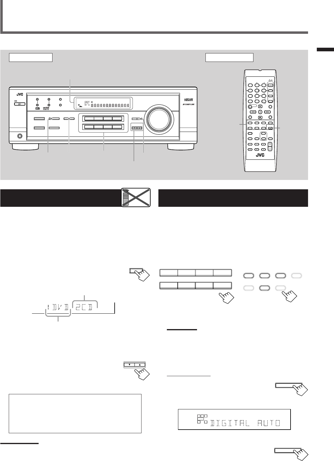
11
Selecting the Analog or Digital Input
Mode
When you have connected digital source components using both the
analog connections (see page 6) and the digital connections (see
page 7) methods, you need to select the input mode correctly.
1
Press one of the source selecting buttons—DVD,
TV SOUND, CD, or TAPE/CDR*—for which you
want to change the input mode.
Note:
*
Among the sources listed above, you can select the digital input
only for the sources which you have selected the digital input
terminals for. (See “Setting the Digital Input (DIGITAL IN)
Terminals” on the left column.)
2
Select digital input mode.
On the front panel:
Press INPUT DIGITAL.
“DIGITAL AUTO” appears on the display and
the indicator for the detected signals also lights
up.
Ex: With the incoming signals of Linear PCM
To change the input mode back to analog
input, press INPUT ANALOG.
“ANALOG” appears on the display and the
analog indicator also lights up.
Setting the Digital Input
[DIGITAL IN] Terminals
When you use the digital input terminals, register what components
are connected to which terminals (DIGITAL 1/2) so that the correct
source name will appear when you select the digital source.
Before you start, remember...
There is a time limit in doing the following steps. If the setting is
canceled before you finish, start from step
1
again.
1
Press SETTING repeatedly until
“DIGITAL IN” appears on the display.
Then the display changes to show the current setting.
* “1DVD 2CD” is the initial setting. If you have already
changed the setting, another combination will be shown.
2
Press CONTROL UP 5/DOWN ∞ to
select the appropriate digital terminal
setting.
•Each time you press the button, the display
changes as follows:
1 DVD 2 CD j1 DVD 2 TV j1 DVD 2 CDR j
1 CD 2 DVD j1 CD 2 TV j1 CD 2 CDR j
1 TV 2 DVD j1 TV 2 CD j1 TV 2 CDR j
1 CDR 2 DVD j1 CDR 2 CD j1 CDR 2 TV j
(back to the beginning)
Note:
When shipped from the factory, the DIGITAL IN terminals can be used
as the digital input for the following components:
–DIGITAL 1 (coaxial): For DVD player
–DIGITAL 2 (optical): For CD player
Basic Settings
Basic Operations / Basic Settings
Front Panel Remote Control
Display
Source
selecting
buttons
CONTROL
UP 5/DOWN ∞
ANALOG/
DIGITAL
SETTING
Remote
NOT
INPUT
DIGITAL
Source
selecting
buttons
SETTING
INPUT
ANALOG
FM MODE
A/V CONTROL
RECEIVER
AUDIO
TV
VCR
DVD
TEST
EFFECT
MENU
ENTER
RETURN
SOUND
SLEEP
CENTER
REAR L
SUBWOOFER
CD–DISC
REC PAUSE
TAPE/CDR CD DVD DVD MULTI
FM/AM
FM MODE
DIMMER TV/VIDEO
SURROUND
ON/OFF
MODE
MUTING
VCR CH TV CH
VOLUME
TV SOUND VCR ANALOG
/DIGITAL
REAR R
100
1
4
7/P
10
2
5
8
0
3
6
9
10
REMOTE CONTROL RM-SRX6020J
REW FF
TV VOLUME
STANDBY/ON
DVDDVD MULTI VCR TV SOUND
ADJUST
RX-6020V
AUDIO/VIDEO CONTROL RECEIVER
SETTING
MASTER VOLUME
CONTROL
DOWN UP
CD TAPE/CDR
SOURCE NAME
INPUT DIGITALINPUT ANALOG
SPEAKERS ON/OFF
SURROUND MODE
PHONES
SURROUND ON/OFF
FM/AM TUNING
STANDBY
FM/AM PRESET FM MODE
MEMORY
INPUT ATT
FM AM
DIGITAL
SURROUND
STANDBY/ON
LC
LS RS
CH-
S
SPK
PRO LOGIC ΙΙ DSP H.PHONE
AUTO MUTING
TUNED STEREO
VOLUME
INPUT ATT
SLEEP
DIGITAL AUTO
ANALOG
DIGITAL
LINEAR PCM
R
S.WFR
CONTROL
DOWN UP
S.WFR
LS RS
CH-
S
LFE
DIGITAL 2 terminal setting
DIGITAL 1 terminal setting
TO BE CONTINUED ON THE NEXT PAGE
DVDDVD MULTI VCR TV SOUND
CD TAPE/CDR
SOURCE NAME
FM AM
TAPE/CDR CD DVD DVD MULTI
FM/AM TV SOUND VCR
On the front panel From the remote control
L
S.WFR
CH-
S
SPK
DIGITAL AUTO
LINEAR PCM
R
INPUT DIGITAL
INPUT ANALOG
INPUT ATT
EN08-17.RX-6020V[J]_f 01.12.7, 11:33 AM11
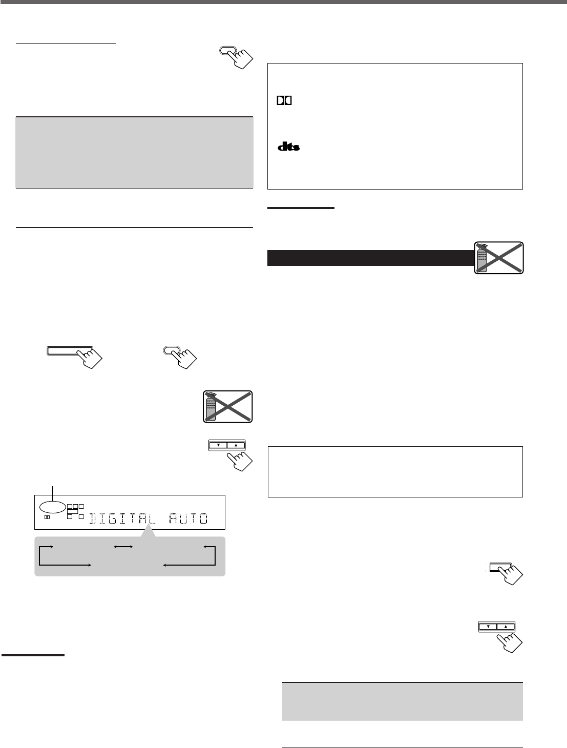
12
The following are the analog/digital signal indicators on the display to
indicate what type of the signal comes into the receiver.
ANALOG : Lights when the analog input is selected.
LINEAR PCM : Lights when Linear PCM signals come in.
DIGITAL :•Lights when Dolby Digital signals come in.
•Flashes when “DOLBY DIGITAL” is
selected for software not encoded with Dolby
Digital signals.
:•Lights when DTS signals come in.
•Flashes when “DTS SURROUND” is
selected for software not encoded with DTS
signals.
Note:
When “DIGITAL AUTO” cannot recognize the incoming signals, no
digital signal indicator lights up on the display.
Setting the Speaker Information
To obtain the best possible sound or effect from Surround modes
(see page 21-23), register the following speakers and subwoofer
information after all connections are completed.
The following are items you can set:
•Subwoofer information—SUBWOOFER
•Speaker size—FRNT SP, CNTR SP, REAR SP
•Speaker distance—UNIT, FRNT DIS, CNTR DIS, REAR DIS
•Crossover frequency—CROSS
•Low frequency effect attenuator—LFE ATT
•Dynamic range compression—D. COMP
Before you start, remember...
There is a time limit in doing the following steps. If the setting is
canceled before you finish, start from step
1
again.
“NO” for the subwoofer, “LARGE” for the front speakers,
and “SMALL” for the center and rear speakers are initial
settings. To get best possible sound, change the subwoofer and
speaker settings to fit your listening conditions.
Subwoofer information
Register whether you have connected a subwoofer or not.
1
Press SETTING repeatedly until
“SUBWOOFER” (with the current
setting) appears on the display.
2
Press CONTROL UP 5/DOWN ∞
to register whether you have
connected a subwoofer or not.
•Each time you press the button, the
subwoofer setting alternates between “YES” and “NO.”
YES : Select this when you have connected a subwoofer.
You can adjust the subwoofer output level
(see page 15).
NO : Select this when you have not connected or have
disconnected a subwoofer.
From the remote control:
Press ANALOG/DIGITAL.
The current setting indication appears on the display.
•Each time you press the button, the input mode alternates
between the analog input (“ANALOG”) and the digital input
(“DIGITAL AUTO”).
DIGITAL AUTO : Select this for the digital input mode. The
receiver automatically detects the
incoming signal format. (The DIGITAL
AUTO indicator lights up on the display,
then the digital signal indicator for the
detected signals lights up.)
ANALOG : Select this for the analog input mode.
(Initial setting when shipped from the
factory.)
If the following symptoms occur while playing Dolby Digital or
DTS Digital Surround software with “DIGITAL AUTO”
selected, follow the procedure below:
–Sound does not come out at the beginning of playback.
–Noise comes out while searching or skipping chapters or tracks.
1
Press INPUT DIGITAL (or ANALOG/DIGITAL on the remote
control).
“DIGITAL AUTO” appears on the display.
On the front panel From the remote control
2
Press CONTROL UP 5/DOWN ∞ to select
“DOLBY DIGITAL” or “DTS SURROUND”
while “DIGITAL AUTO” still remains on the
display.
•Each time you press the button, the digital input
mode changes as follows:
When “DOLBY DIGITAL” or “DTS
SURROUND” is selected, “DIGITAL AUTO” goes off.
•To play back software encoded with Dolby Digital, select
“DOLBY DIGITAL.”
•To play back software encoded with DTS Digital Surround,
select “DTS SURROUND.”
Note:
When you turn off the power or select another source, “DOLBY
DIGITAL” and “DTS SURROUND” are canceled and the digital input
mode is automatically reset to “DIGITAL AUTO.”
Basic Settings
ANALOG
/DIGITAL
ANALOG
/DIGITAL
INPUT DIGITAL
Remote
NOT
CONTROL
DOWN UP
LC
S.WFR
LS RS
CH-
S
LFE
SPK
DIGITAL AUTO
DIGITAL
R
DIGITAL AUTO DTS SURROUND
DOLBY DIGITAL
T SETTING
Remote
NOT
CONTROL
DOWN UP
EN08-17.RX-6020V[J]_f 01.12.7, 11:33 AM12
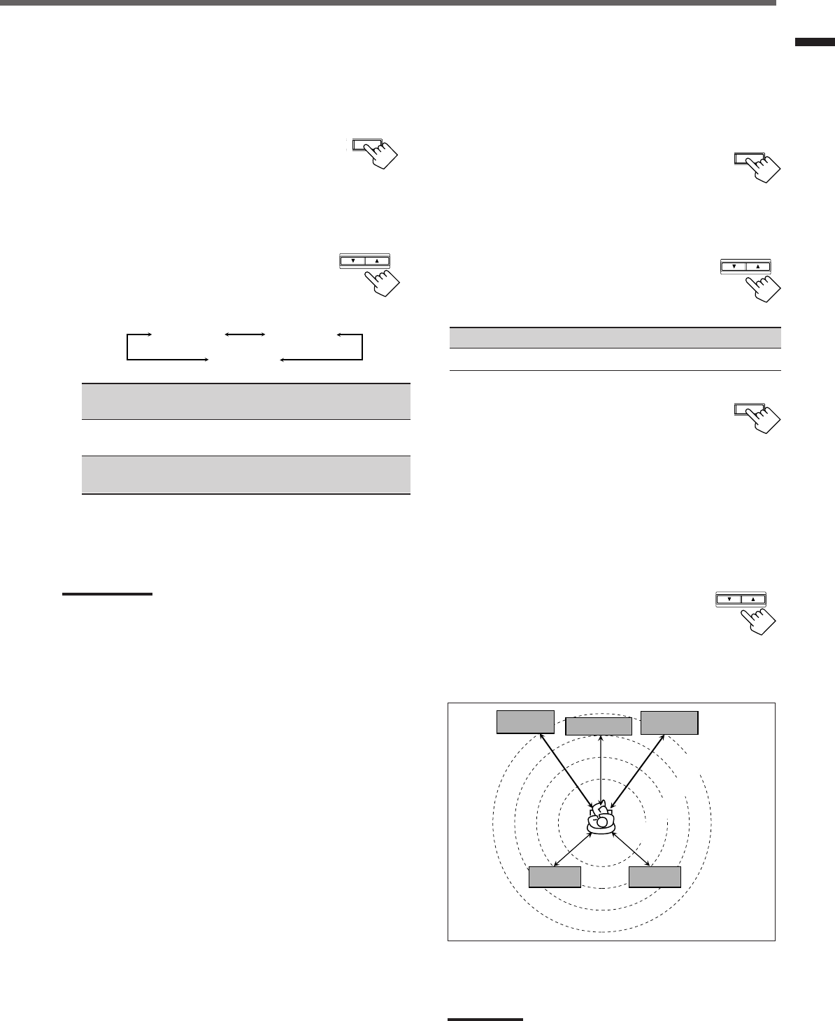
13
Basic Settings
Speaker distance
Register the unit you use, then the speaker distance from your
listening point.
• If you have set the unit before, start from step
3
.
• Speaker distance is not valid for the DVD MULTI playback mode.
1
Press SETTING repeatedly until
“UNIT” (with the current setting)*
appears on the display.
* “METER” is the initial setting. If you have already changed the
setting, “FEET” will be shown.
2
Press CONTROL UP 5/DOWN ∞ to
select the unit.
• Each time you press the button, the setting
alternates between “METER” and “FEET.”
METER : Speaker distance is shown in meter.
FEET : Speaker distance is shown in feet.
3
Press SETTING repeatedly until
“FRNT DIS (Front distance),” “CNTR
DIS (Center distance),” or “REAR DIS
(Rear distance)” (with the current setting)*
appears on the display.
• The display shows the current setting in the unit selected in
step
2
.
* “3.0m” is the initial setting for meter and “10FT” is for feet. If
you have already changed the setting, another value will be
shown.
4
Press CONTROL UP 5/DOWN ∞
to select the appropriate speaker
distance.
• If you have selected “METER” in step
2
, the
value is changed from “0.3m” to “9.0m” by 0.3 m step.
• If you have selected “FEET” in step
2
,
the value is changed
from “1FT” to “30FT” by 1 foot step.
Example: In this case,
set “FRNT DIS” to “3.0m” or “10FT,”
set “CNTR DIS” to “2.7m” or “9FT” and,
set “REAR DIS” to “2.4m” or “8FT.”
Note:
If you have selected “NONE” for the center and rear speakers
setting, you cannot set the speaker distance for the center and rear
speakers.
T SETTING
Speaker size
Register the sizes of all the connected speakers.
•When you change your speakers, register the information about the
speakers again.
1
Press SETTING repeatedly until
“FRNT SP (Front speaker),” “CNTR
SP (Center speaker),” or “REAR SP
(Rear speaker)” (with the current setting)
appears on the display.
2
Press CONTROL UP 5/DOWN ∞ to
select the appropriate item about the
speaker selected in the above step.
•Each time you press the button, the display
changes as follows:
LARGE : Select this when the speaker size is relatively large.
(See “Notes” below.)
SMALL : Select this when the speaker size is relatively small.
(See “Notes” below.)
NONE : Select this when you have not connected a speaker.
(Not selectable for the front speakers)
3
Repeat step
1
and
2
to select the appropriate
items for other speakers.
Notes:
•Keep the following comment in mind as reference when adjusting.
–If the size of the cone speaker unit built in your speaker is greater
than 12 cm (4
3
/
4
inches), select “LARGE,” and if it is smaller than
12 cm (4
3
/
4
inches), select “SMALL.”
•If you have selected “NO” for the subwoofer setting, you can only
select “LARGE” for the front speaker setting.
•If you have selected “SMALL” for the front speaker setting, you
cannot select “LARGE” for the center and rear speaker settings.
SETTING
CONTROL
DOWN UP
SETTING
CONTROL
DOWN UP
3.0 m
(10 feet)
Left front
speaker Right front
speaker
Right rear
speaker
Left rear
speaker
Center speaker
2.7 m
(9 feet)
2.4 m
(8 feet)
2.1 m
(7 feet)
CONTROL
DOWN UP
LARGE SMALL
NONE
EN08-17.RX-6020V[J]_f 01.12.7, 4:17 PM13
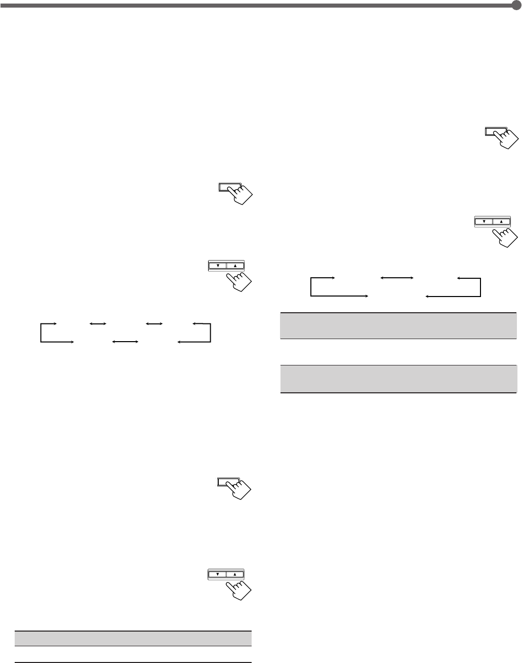
14
SETTING
CONTROL
DOWN UP
Dynamic range compression
You can compress the dynamic range (difference between maximum
sound and minimum sound) of the reproduced sound. This is useful
when enjoying surround sound at night.
•This function takes effect only when playing back a source
encoded with Dolby Digital.
1
Press SETTING repeatedly until
“D. COMP (Dynamic range
compression)” (with the current setting)*
appears on the display.
*“MID” is the initial setting. If you have already changed the
setting, another setting will be shown.
2
Press CONTROL UP 5/DOWN ∞
to select the appropriate compression
level.
•Each time you press the button, the display changes
as follows:
OFF : Select this when you want to enjoy surround with its
full dynamic range. (No effect applied.)
MID : Select this when you want to reduce the dynamic range
a little.
MAX : Select this when you want to apply the compression
effect fully. (Useful at night.)
Basic Settings
Crossover frequency
Small speakers cannot reproduce the bass sounds efficiently. If you
use a small speaker in any position, this receiver automatically
reallocates the bass sound elements assigned from small speakers to
large speakers.
To use this function properly, set this crossover frequency level
according to the size of the small speaker connected.
•If you have selected “LARGE” for all speakers, this function will
not take effect.
•Crossover frequency is not valid for DVD MULTI playback mode
and HEADPHONE mode.
1
Press SETTING repeatedly until “CROSS
(Crossover)” (with the current setting)*
appears on the display.
*“100HZ” is the initial setting. If you have already changed the
setting, another frequency will be shown.
2
Press CONTROL UP 5/DOWN ∞ to
select the crossover frequency level you
like to use.
•Each time you press the button, the crossover
frequency level changes as follows:
Low frequency effect attenuator
If the bass sound is distorted while playing back software using
Dolby Digital or DTS Digital Surround, follow the procedure
below:
•Low frequency effect attenuator is not valid for the DVD MULTI
playback mode.
•This function takes effect only when the subwoofer (LFE) signals
come in, (with “SUBWOOFER” set to “YES”).
1
Press SETTING repeatedly until “LFE
ATT (Low Frequency Effect Attenuator)”
(with the current setting)* appears on the
display.
*“0dB” is the initial setting. If you have already changed the
setting, “–10dB” will be shown.
2
Press CONTROL UP 5/DOWN ∞ to
select the low frequency effect
attenuator level.
•Each time you press the button, the setting
alternates between “0dB” and “–10dB.”
0dB : Normally select this.
–10dB : Select this when the bass sound is distorted.
SETTING
CONTROL
DOWN UP
SETTING
CONTROL
DOWN UP
100HZ
80HZ 120HZ
150HZ200HZ
OFF MID
MAX
EN08-17.RX-6020V[J]_f 01.12.7, 11:33 AM14
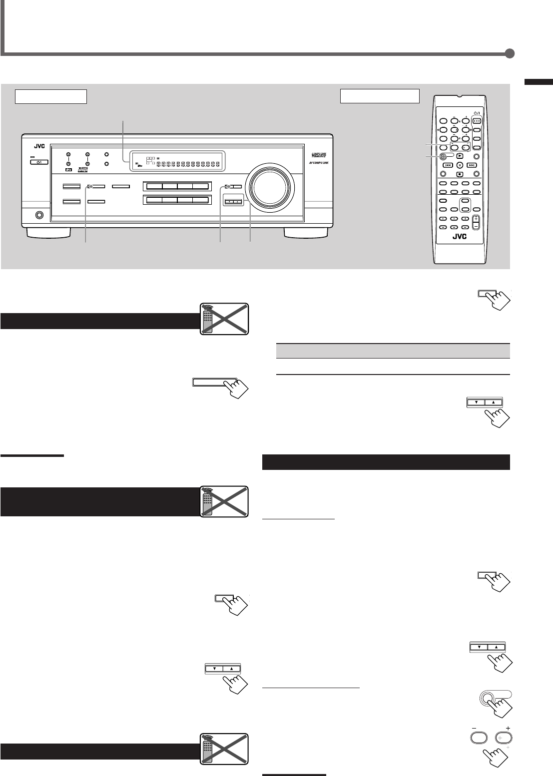
15
Once each of following settings has been adjusted, this receiver
memorizes the adjustments for each source.
Attenuating the Input Signal
When the input level of the analog source is too high, sounds will
be distorted. If this happens, you need to attenuate the input signal
level to prevent the sound distortion.
1
Press and hold INPUT ATT (INPUT
ANALOG) so that the INPUT ATT
indicator lights up on the display.
•Each time you press and hold the button, the Input Attenuator
mode turns on (“INPUT ATT ON”) or off (“INPUT
NORMAL”).
Note:
When selecting “DVD MULTI” as the source, this effect does not work.
Adjusting the Front Speakers
Output Balance
If the sounds you hear from the front right and left speakers are
unequal, you can adjust the speaker output balance.
Before you start, remember...
There is a time limit in doing the following steps. If the setting is
canceled before you finish, start from step
1
again.
1
Press ADJUST repeatedly until
“BALANCE” (with the current setting)*
appears on the display.
*“CNTR (Center)” is the initial setting. If you have already
changed the setting, another setting will be shown.
2
Press CONTROL UP 5/DOWN ∞
to adjust the balance.
•Pressing CONTROL UP 5 decreases the
left channel output from “CNTR (Center)”
to “L–21.”
•Pressing CONTROL DOWN ∞ decreases
the right channel output from “CNTR (Center)” to “R–21.”
Adjusting the Tone
You can adjust the bass and treble sounds as you like.
Before you start , remember...
There is a time limit in doing the following steps. If the setting is
canceled before you finish, start from step
1
again.
Sound Adjustments
SUBWOOFER +/–
SOUND
Basic Settings / Sound Adjustments
Front Panel Remote Control
ADJUST
FM MODE
A/V CONTROL
RECEIVER
AUDIO
TV
VCR
DVD
TEST
EFFECT
MENU
ENTER
RETURN
SOUND
SLEEP
CENTER
REAR L
SUBWOOFER
CD–DISC
REC PAUSE
TAPE/CDR CD DVD DVD MULTI
FM/AM
FM MODE
DIMMER TV/VIDEO
SURROUND
ON/OFF
MODE
MUTING
VCR CH TV CH
VOLUME
TV SOUND VCR ANALOG
/DIGITAL
REAR R
100
1
4
7/P
10
2
5
8
0
3
6
9
10
REMOTE CONTROL RM-SRX6020J
REW FF
TV VOLUME
STANDBY/ON
INPUT ANALOG
INPUT ATT
Display
INPUT ATT ADJUST CONTROL
UP 5/DOWN ∞
DVDDVD MULTI VCR TV SOUND
ADJUST
RX-6020V AUDIO/VIDEO CONTROL RECEIVER
SETTING
MASTER VOLUME
CONTROL
DOWN UP
CD TAPE/CDR
SOURCE NAME
INPUT DIGITALINPUT ANALOG
SPEAKERS ON/OFF
SURROUND MODE
PHONES
SURROUND ON/OFF
FM/AM TUNING
STANDBY
FM/AM PRESET FM MODE
MEMORY
INPUT ATT
FM AM
DIGITAL
SURROUND
STANDBY/ON
LC
S.WFR
LS RS
CH-
S
LFE
SPK
PRO LOGIC ΙΙ DSP H.PHONE
AUTO MUTING
TUNED STEREO
VOLUME
INPUT ATT
SLEEP
DIGITAL AUTO
ANALOG
DIGITAL
LINEAR PCM
R
Remote
NOT
Remote
NOT
Remote
NOT
CONTROL
DOWN UP
ADJUST
CONTROL
DOWN UP
SOUND
CONTROL
DOWN UP
ADJUST
1
Press ADJUST repeatedly until “BASS”
or “TREBLE” (with the current setting)*
appears on the display.
*“0” is the initial setting. If you have already changed the
setting, another number (level) will be shown.
BASS : To adjust the bass (–10 to +10).
TREBLE : To adjust the treble (–10 to +10).
2
Press CONTROL UP 5/DOWN ∞ to
adjust the bass or treble sound level.
•Each time you press the button, the sound
level changes by ±2 steps.
Adjusting the Subwoofer Output Level
You can adjust the subwoofer output level if you have connected a
subwoofer and set the subwoofer information correctly—“YES.”
On the front panel:
Before you start, remember...
There is a time limit in doing the following steps. If the setting is
canceled before you finish, start from step
1
again.
1
Press ADJUST repeatedly until
“SUBWFR (Subwoofer)” (with the
current setting)* appears on the display.
*“0” is the initial setting. If you have already changed the
setting, another number (level) will be shown.
2
Press CONTROL UP 5/DOWN ∞ to
adjust the subwoofer output level
(–10 to +10).
From the remote control:
1
Press SOUND.
10 keys are activated for sound adjustments.
2
Press SUBWOOFER +/– to adjust
the subwoofer output level
(–10 to +10).
Note:
Subwoofer output level cannot be adjusted when using headphones.
SUBWOOFER
010
100
EN08-17.RX-6020V[J]_f 01.12.7, 11:33 AM15
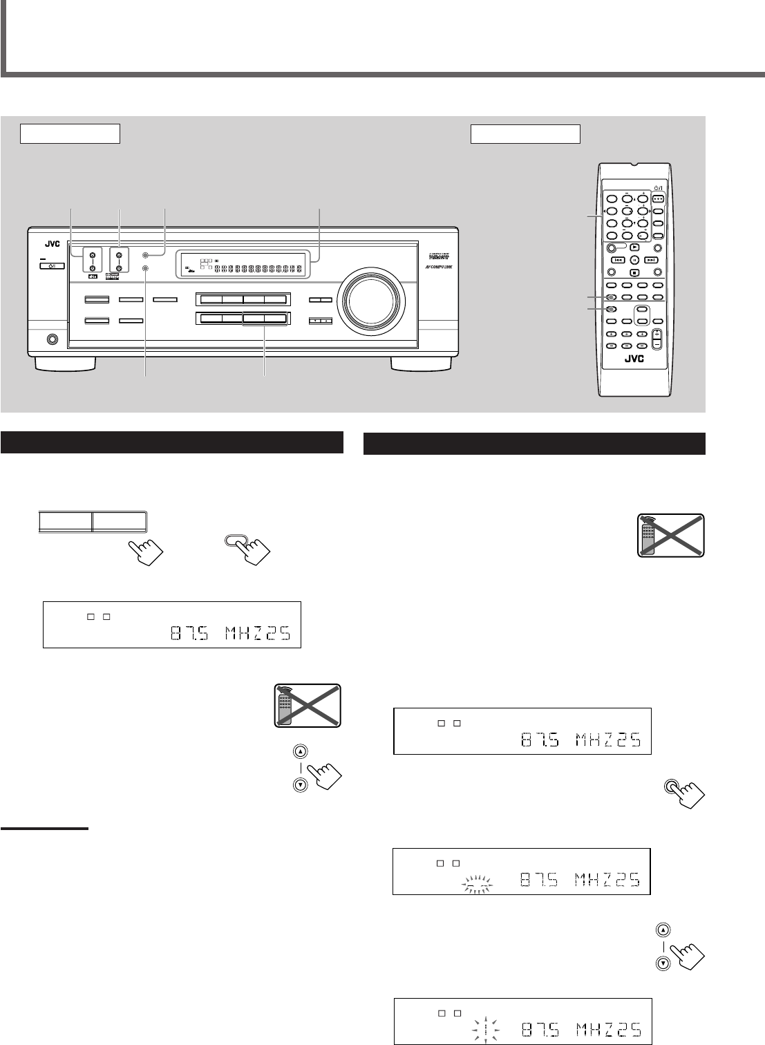
16
Tuning in Stations
1
Press FM or AM (FM/AM) to select the band.
The last received station of the selected band is tuned in.
2
Press FM/AM TUNING 5/∞
(up/down) repeatedly until you find
the frequency you want.
•Pressing FM/AM TUNING 5 (up)
increases the frequency.
•Pressing FM/AM TUNING ∞ (down)
decreases the frequency.
Notes:
•When you press and hold FM/AM TUNING
5
/
∞
(up/down) for few
seconds in step
2
, the frequency keeps changing until a station is
tuned in.
•When a station of sufficient signal strength is tuned in, the TUNED
indicator lights up on the display.
•When an FM stereo program is received, the STEREO indicator
also lights up.
Tuner Operations
Front Panel Remote Control
Display 10 keys
FM MODE
FM/AM
Remote
NOT
Using Preset Tuning
Once a station is assigned to a channel number, the station can be
quickly tuned. You can preset up to 30 FM and 15 AM stations.
To store the preset stations
Before you start, remember...
There is a time limit in doing the following steps. If the setting is
canceled before you finish, start from step
2
again.
1
Tune in the station you want to preset
(see “Tuning in Stations” on the left).
•If you want to store the FM reception mode for each preset
station, select the FM reception mode. See “Selecting the FM
Reception Mode” on page 17.
2
Press MEMORY.
The “CH-” indicator lights up and the channel
number position starts flashing on the display for
about 5 seconds.
3
Press FM/AM PRESET 5/∞ (up/
down) to select a channel number
while the channel number position
is flashing.
LC
S.WFR
LS RS
CH-
S
LFE
SPK AUTO MUTING
TUNED STEREO
VOLUME
ANALOG
R
MEMORY
LC
S.WFR
LS RS
CH-
S
LFE
SPK AUTO MUTING
TUNED STEREO
VOLUME
ANALOG
R
LC
S.WFR
LS RS
CH-
S
LFE
SPK AUTO MUTING
TUNED STEREO
VOLUME
ANALOG
R
FM/AM PRESET
MEMORY FM/AM
FM MODE
FM MODE
A/V CONTROL
RECEIVER
AUDIO
TV
VCR
DVD
TEST
EFFECT
MENU
ENTER
RETURN
SOUND
SLEEP
CENTER
REAR L
SUBWOOFER
CD–DISC
REC PAUSE
TAPE/CDR CD DVD DVD MULTI
FM/AM
FM MODE
DIMMER TV/VIDEO
SURROUND
ON/OFF
MODE
MUTING
VCR CH TV CH
VOLUME
TV SOUND VCR ANALOG
/DIGITAL
REAR R
100
1
4
7/P
10
2
5
8
0
3
6
9
10
REMOTE CONTROL RM-SRX6020J
REW FF
TV VOLUME
STANDBY/ON
FM/AM
PRESET
5/∞
(up/down)
FM/AM
TUNING
5/∞
(up/down)
DVDDVD MULTI VCR TV SOUND
ADJUST
RX-6020V
AUDIO/VIDEO CONTROL RECEIVER
SETTING
MASTER VOLUME
CONTROL
DOWN UP
CD TAPE/CDR
SOURCE NAME
INPUT DIGITALINPUT ANALOG
SPEAKERS ON/OFF
SURROUND MODE
PHONES
SURROUND ON/OFF
FM/AM TUNING
STANDBY
FM/AM PRESET FM MODE
MEMORY
INPUT ATT
FM AM
DIGITAL
SURROUND
STANDBY/ON
LC
S.WFR
LS RS
CH-
S
LFE
SPK
PRO LOGIC ΙΙ DSP H.PHONE
AUTO MUTING
TUNED STEREO
VOLUME
INPUT ATT
SLEEP
DIGITAL AUTO
ANALOG
DIGITAL
LINEAR PCM
R
LC
S.WFR
LS RS
CH-
S
LFE
SPK AUTO MUTING
TUNED STEREO
VOLUME
ANALOG
R
Ex.: When the FM band is selected.
On the front panel From the remote control
FM AM
FM/AM
FM/AM TUNING
Remote
NOT
EN08-17.RX-6020V[J]_f 01.12.7, 11:33 AM16
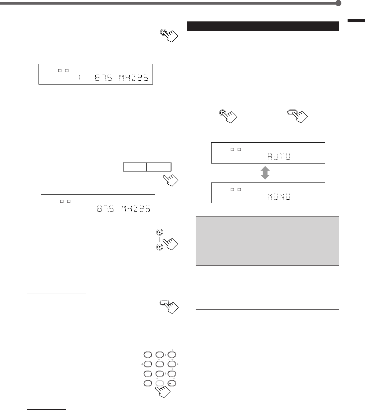
17
Tuner Operations
4
Press MEMORY again while the
selected channel number is flashing
on the display.
The selected channel number stops flashing.
The station is assigned to the selected channel number.
5
Repeat steps
1
to
4
for storing more stations.
To erase a stored preset station
Storing a new station on a used number erases the previously stored
one.
To tune in a preset station
On the front panel:
1
Press FM or AM to select the
band.
The last received station of the
selected band is tuned in.
2
Press FM/AM PRESET 5/∞
(up/down) repeatedly until you find
the channel you want.
•Pressing FM/AM PRESET 5 (up)
increases the channel numbers.
•Pressing FM/AM PRESET ∞ (down)
decreases the channel numbers.
From the remote control:
1
Press FM/AM to select the band (FM or
AM).
The last received station of the selected band is tuned
in and 10 keys now work for tuner operation.
•Each time you press the button, the band
alternates between FM and AM.
2
Press 10 keys to select a preset
channel number.
•For channel number 5, press 5.
•For channel number 15, press +10 then 5.
•For channel number 20, press +10 then 10.
•For channel number 30, press +10, +10,
then 10.
Note:
When you use 10 keys on the remote control, be sure that they are
activated for the tuner, not for the CD player and others. (See page
28.)
LC
S.WFR
LS RS
CH-
S
LFE
SPK AUTO MUTING
TUNED STEREO
VOLUME
ANALOG
R
MEMORY
FM/AM PRESET
FM/AM
TEST
EFFECT
MENU
ENTER
CENTER
REAR L
SUBWOOFER
REAR R
1
4
7/P
10
2
5
8
0
3
6
9
10
100
RETURN
LC
S.WFR
LS RS
CH-
S
LFE
SPK AUTO MUTING
TUNED STEREO
VOLUME
ANALOG
R
Selecting the FM Reception Mode
When an FM stereo broadcast is hard to receive or noisy, you can
change the FM reception mode while receiving an FM broadcast.
•You can store the FM reception mode for each preset station (see
page 16).
1
While listening to an FM station, press
FM MODE.
•Each time you press the button, the FM reception mode
alternates between “AUTO” and “MONO.”
AUTO : Normally select this.
When a program is broadcasted in stereo, you will
hear stereo sound; when in monaural, you will
hear monaural sounds. This mode is also useful to
suppress static noise between stations. The AUTO
MUTING indicator lights up on the display.
(Initial Setting)
MONO : Select this to improve the reception (but stereo
effect will be lost).
In this mode, you will hear noise while tuning into
the stations. The AUTO MUTING indicator goes
off from the display. (The STEREO indicator also
goes off.)
FM MODE
From the remote control
FM MODE
On the front panel
LC
S.WFR
LS RS
CH-
S
LFE
SPK AUTO MUTING
TUNED STEREO
ANALOG
R
LC
S.WFR
LS RS
CH-
S
LFE
SPK TUNED
ANALOG
R
FM AM
EN08-17.RX-6020V[J]_f 01.12.7, 11:33 AM17
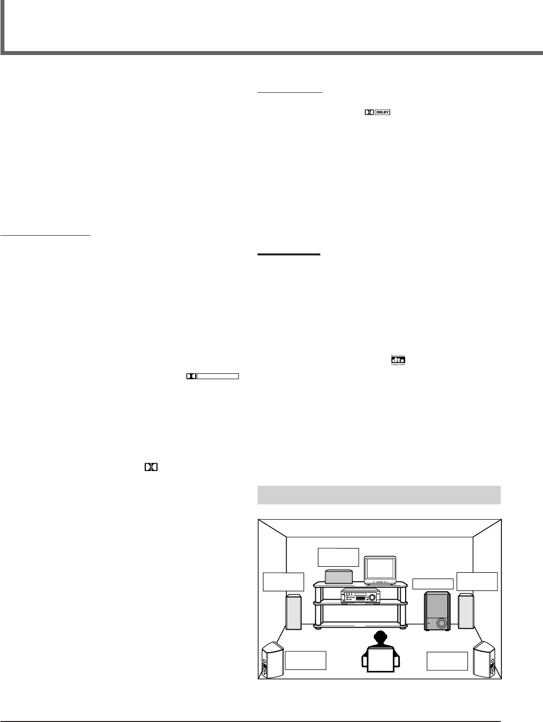
18
*
Manufactured under license from Dolby Laboratories. “Dolby,” “Pro
Logic,” and the double-D symbol are trademarks of Dolby
Laboratories. Confidential Unpublished Works. ©1992–1997 Dolby
Laboratories, Inc. All rights reserved.
Creating Realistic Sound Fields
You can use the following Surround modes to reproduce a realistic
sound field:
■Dolby Surround
•Dolby Pro Logic II
•Dolby Digital
■DTS Digital Surround
■DAP modes
■All Channel Stereo
■ Dolby Surround
Dolby Pro Logic II*
Dolby Pro Logic II has a newly developed multichannel playback
format to decode all 2 channel sources—regular stereo source and
Dolby Surround encoded source—into 5.1 channel.
Matrix-based encoding/decoding method for Dolby Pro Logic II
makes no limitation for the cutoff frequency of the rear treble and
enables stereo rear sound compared to conventional Dolby Pro
Logic.
Dolby Pro Logic II enables to reproduce spacious sound from
original sound without adding any new sounds and tonal colorations.
Dolby Pro Logic II has two modes—Movie mode and Music mode:
Pro Logic II Movie (PL II MOVIE)—suitable for reproduction of
Dolby Surround encoded sources bearing the mark
DOLBY SURROUND
.
You can enjoy soundfield very close to the one created with discrete
5.1 channel sounds.
Pro Logic II Music (PL II MUSIC)—suitable for reproduction of
any 2 channel stereo music sources. You can enjoy wide and deep
sound by using this mode. For this mode, Panorama control can be
selected, which gives “wraparound” sound effect with side-wall
image.
•When Dolby Pro Logic II is activated, PRO LOGIC II
indicator lights up on the display.
Dolby Digital*
Used to reproduce multichannel sound tracks of the software
encoded with Dolby Digital (
DIGITAL
).
•To enjoy the software encoded with Dolby Digital, connect the
source component using the digital terminal on the rear of this
receiver. (See page 7.)
Dolby Digital 5.1 ch encoding method (so-called discrete
multichannel digital audio format) records and digitally compresses
the left front channel, right front channel, center channel, left rear
channel, right rear channel, and LFE channel signals.
Since each channel is completely independent from the other
channel signals to avoid interference, you can obtain much better
sound quality with much stereo and surround effects.
Note:
Dolby Digital software can be roughly grouped into two categories
—multichannel (up to “5.1” ch) and 2 channel software. To enjoy
surround sounds while playing Dolby Digital 2 ch software, you can
use Dolby Pro Logic II.
■ DTS Digital Surround**
Used to reproduce multichannel sound tracks of the software
encoded with DTS Digital Surround ( ).
•To enjoy the software encoded with DTS Digital Surround,
connect the source component using the digital terminal on the
rear of this receiver. (See page 7.)
DTS Digital Surround is another discrete multichannel digital
audio format available on CD, LD, and DVD software.
Compared to Dolby Digital, audio compression ratio is relatively
low. This fact allows DTS Digital Surround format to add breadth
and depth to the reproduced sounds. As a result, DTS Digital
Surround features natural, solid and clear sound.
**
Manufactured underlicense from Digital Theater Systems, Inc. US
PAT. No. 5,451,942 and other world-wide patents issued and
pending. “DTS” and “DTS Digital Surround” are trademarks of
Digital Theater Systems, Inc. Copyright 1996 Digital Theater
Systems, Inc. All rights reserved.
Typical Multichannel (5.1 ch) reproduction
Right rear
speaker
Left front
speaker Subwoofer
Center
speaker
Left rear
speaker
Right front
speaker
DVD VCR TV SOUND
ADJUST
RX-6020V AUDIO/VIDEO CONTROL RECEIVER
SETTING
MASTER VOLUME
CONTROL
DOWN UP
CD TAPE/CDR
SOURCE NAME
INPUT DIGITALINPUT ANALOG
SPEAKERS ON/OFF
SURROUND MODE
PHONES
SURROUND ON/OFF
FM/AM TUNING
STANDBY
FM/AM PRESET FM MODE
MEMORY
INPUT ATT
AM
DIGITAL
SURROUND
STANDBY/ON
DVD MULTI
FM
EN18-23.RX-6020V[J]_f 01.12.7, 11:34 AM18
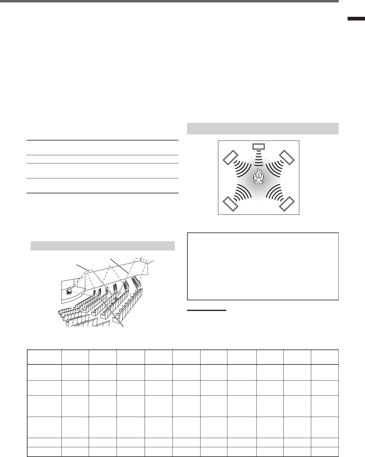
19
Creating Realistic Sound Fields
■ DAP (Digital Acoustic Processor) modes
DAP modes have been designed to create important acoustic
surround elements.
The sound heard in a live club, dance club, hall or pavilion consists
of direct sound and indirect sound—early reflections and reflections
from behind. Direct sounds reach the listener directly without any
reflection. On the other hand, indirect sounds are delayed by the
distances of the ceiling and walls (see the diagram below).
These indirect sounds are important elements of the acoustic
surround effects. The DAP mode can reproduce a realistic sound
field by adding these indirect sounds.
DAP modes can be used when the front and rear speakers are
connected to this receiver (without respect to the center speaker
connection: no sound comes out of the center speaker even if it is
connected).
The following DAP modes are provided with this receiver:
LIVE CLUB : Gives the feeling of a live music club with a low
ceiling.
DANCE CLUB : Gives a throbbing bass beat.
HALL : Gives clear vocal and the feeling of a concert
hall.
PAVILION : Gives the spacious feeling of a pavilion with a
high ceiling.
These DAP modes can be used to add the acoustic surround effects
while reproducing 2 channel stereo software—either analog or
digital except Dolby Digital and DTS Digital Surround—and can
give you a real “being there” feeling.
•When one of the DAP modes is selected, the DSP indicator lights
up on the display.
Available Surround modes for each input signal 䡬: Possible / ⳯: Impossible
Mode
SURROUND
DOLBY DTS PLII PLII LIVE DANCE HALL PAVILION ALL CH
Signals
OFF (stereo)
DIGITAL
SURROUND
MOVIE MUSIC CLUB CLUB STEREO
Dolby Digital 䡬䡬⳯⳯⳯⳯⳯ ⳯⳯⳯
(Multichannel)
Dolby Digital 䡬⳯⳯䡬䡬⳯⳯ ⳯⳯⳯
(2 channel)
DTS Digital
Surround 䡬⳯䡬⳯⳯⳯⳯ ⳯⳯⳯
(Multichannel)
DTS Digital
Surround 䡬⳯⳯䡬䡬⳯⳯ ⳯⳯⳯
(2 channel)
Linear PCM 䡬⳯⳯䡬䡬 䡬䡬 䡬䡬䡬
Analog 䡬⳯⳯䡬䡬 䡬䡬 䡬䡬䡬
■ All Channel Stereo
This mode can reproduce a larger stereo sound field using all the
connected (and activated) speakers.
All Channel Stereo can be used when the front and rear
speakers are connected to this receiver without respect to the
center speaker connection.
If the center speaker is connected and activated, the same phase of
the front left and right signals are output through the center speaker.
All Channel Stereo can be used while reproducing 2 channel stereo
software, either analog or digital except Dolby Digital and DTS
Digital Surround.
•When All Channel Stereo is selected, the DSP indicator lights up
on the display.
DVD MULTI Playback Mode
This receiver provides the DVD MULTI Playback Mode for
reproducing the analog discrete 5.1 channel output mode of the
DVD player or other equipment.
You can adjust speaker output levels while playing back a video
software such as a DVD using the analog discrete 5.1 channel
output mode.
•For connecting analog discrete output jacks, see page 7.
•For details on the DVD MULTI Playback Mode, see page 24.
Note:
When you select “DVD MULTI” as the source to play, Surround mode
is canceled, and the SURROUND ON/OFF and SURROUND MODE
buttons do not work.
All Channel Stereo reproduction
Sound reproduced from All Channel Stereo
Creating sound field
Early reflections
Reflections from behind
Direct sounds
EN18-23.RX-6020V[J]_f 01.12.7, 11:34 AM19
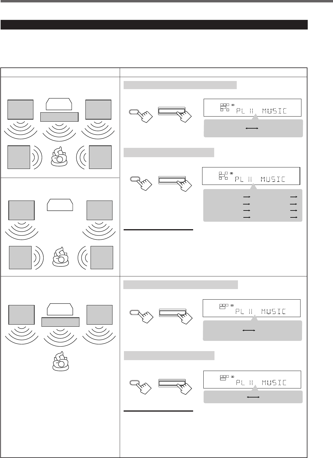
20
About Relations between Speaker Layout and Surround Modes
Available Surround modes will vary depending on how many speakers are used with this receiver.
Make sure that you have set the speaker information correctly (see pages 12 to 14).
•If only front speakers are connected, you cannot use any Surround modes.
•If rear speakers are not connected, you cannot use the DAP modes and All Channel Stereo.
Creating Realistic Sound Fields
Speaker Layout Available Surround modes
When the center and rear speakers
are connected (5 channels):
Ex.: “PL II MUSIC” has been selected.
Turning on or off Surround modes
Each time you press SURROUND ON/OFF, Surround modes turn on or off.
L
S.WFR
SPK
PRO LOGIC ΙΙ DSP H.PHONE
AUTO MUTING
TUNED STEREO
INPUT ATT
DIGITAL AUTO
LINEAR PCM
R
SURROUND OFF
Last selected
Surround mode
L
S.WFR
SPK
PRO LOGIC ΙΙ DSP H.PHONE
AUTO MUTING
TUNED STEREO
INPUT ATT
DIGITAL AUTO
LINEAR PCM
R
PL II MOVIE
LIVE CLUB DANCE CLUB
ALL CH STEREO
PAVILION
HALL
(Back to the beginning)
PL II MUSIC
Selecting Surround modes
Each time you press SURROUND MODE, Surround modes change as follows:
SURROUND
MODE
SURROUND MODE
(Front panel)
(Remote)
Turning on or off Surround modes
Each time you press SURROUND ON/OFF, Surround modes turn on or off.
Ex.: “PL II MUSIC” has been selected.
L
S.WFR
SPK
PRO LOGIC ΙΙ DSP H.PHONE
AUTO MUTING
TUNED STEREO
INPUT ATT
DIGITAL AUTO
LINEAR PCM
R
SURROUND OFF
PL II MOVIE
or
PL II MUSIC
Front
speaker
When the center speaker is connected
(3 channels):
TV
Rear
speaker
Front
speaker
Rear
speaker
When the rear speakers are connected
(4 channels):
TV
Center speaker
Front
speaker
Front
speaker
Rear
speaker
Rear
speaker
Front
speaker Center speaker
Front
speaker
TV
Selecting Surround modes
Each time you press SURROUND MODE, Surround modes change as follows:
Notes:
When the digital multichannel software such as Dolby Digital or DTS Digital
Surround is played back, the appropriate multichannel Surround mode is
automatically activated (“DOLBY DIGITAL” or “DTS SURROUND”) by pressing
SURROUND ON/OFF (with the digital input mode selected).
•For Dolby Digital 2 ch software, you need to select “PLII MUSIC” or “PLII MOVIE”
by pressing SURROUND MODE.
•For more details, see the table on page 19.
L
S.WFR
SPK
PRO LOGIC ΙΙ DSP H.PHONE
AUTO MUTING
TUNED STEREO
INPUT ATT
DIGITAL AUTO
LINEAR PCM
R
PL II MOVIE PL II MUSIC
Notes:
When the digital multichannel software such as Dolby Digital or DTS Digital
Surround is played back, the appropriate multichannel Surround mode is
automatically activated (“DOLBY DIGITAL” or “DTS SURROUND”) by pressing
SURROUND ON/OFF (with the digital input mode selected).
•For Dolby Digital 2 ch software, you need to select “PLII MUSIC” or “PLII MOVIE”
by pressing SURROUND MODE.
•For more details, see the table on page 19.
SURROUND MODE
(Remote) (Front panel)
(Front panel)(Remote)
SURROUND
ON/OFF
(Remote)
SURROUND ON/OFF
(Front panel)
SURROUND
ON/OFF
SURROUND ON/OFF
SURROUND
MODE
EN18-23.RX-6020V[J]_f 01.12.7, 11:34 AM20
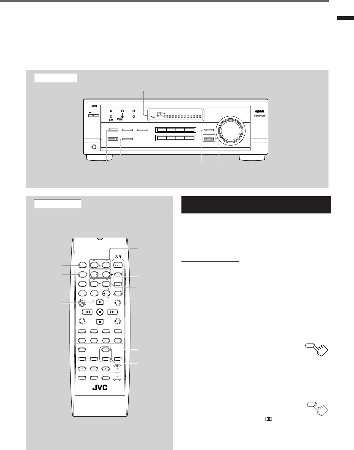
21
Before you start, remember...
•Make sure that you have set the speaker information correctly (see pages 12 to 14).
•You cannot adjust the center speaker output level when you have set “CNTR SP” to “NONE.”
•You cannot adjust the rear speaker output levels when you have set “REAR SP” to “NONE.”
•Remember not to change the speaker setting while using any Surround mode; otherwise, it may be canceled when you deactivate the
speakers required for Surround mode.
Creating Realistic Sound Fields
Using Dolby Pro Logic II, Dolby Digital and
DTS Digital Surround
Once you have adjusted the Surround modes, the adjustment is
memorized for each source.
•When playing back digital multichannel software (Dolby Digital
5.1 ch or DTS Digital Surround), the SURROUND MODE button
does not work.
From the remote control:
It will be convenient for you to use the remote control for
adjustments, since you can make adjustments from your listening
point by using the test signal.
•For selecting Panorama control for Pro Logic II Music, use the
buttons on the front panel.
1
Set the analog or digital input mode for the source
you like to listen and start playing.
When playing back software encoded with Dolby Digital and
DTS Digital Surround, select the digital input mode (see page
11).
2
Press SURROUND ON/OFF to
activate Surround mode.
Each time you press the button, Surround mode
turns on and off alternately.
•If you are playing back software encoded with Dolby Digital
multichannel, “DOLBY DIGITAL” is selected.
•If you are playing back software encoded with DTS Digital
Surround, “DTS SURROUND” is selected.
•If you are playing back any software other
than above, you can select “PL II MUSIC” or
“PL II MOVIE” according to the source by
pressing SURROUND MODE. ( PRO LOGIC II
indicator lights up on the display.)
If you like to adjust sound, go to step
3
.
Remote Control
SURROUND
ON/OFF
SURROUND
MODE
EFFECT
TEST
REAR•R +/–
REAR•L +/–
CENTER +/–
SOUND
FM MODE
A/V CONTROL
RECEIVER
AUDIO
TV
VCR
DVD
TEST
EFFECT
MENU
ENTER
RETURN
SOUND
SLEEP
CENTER
REAR L
SUBWOOFER
CD–DISC
REC PAUSE
TAPE/CDR CD DVD DVD MULTI
FM/AM
FM MODE
DIMMER TV/VIDEO
SURROUND
ON/OFF
MODE
MUTING
VCR CH TV CH
VOLUME
TV SOUND VCR ANALOG
/DIGITAL
REAR R
100
1
4
7/P
10
2
5
8
0
3
6
9
10
REMOTE CONTROL RM -SRX6020J
REW FF
TV VOLUME
STANDBY/ON
Front Panel
Display
SURROUND
ON/OFF
SURROUND
MODE
ADJUST CONTROL
UP 5/DOWN ∞
DVDDVD MULTI VCR TV SOUND
ADJUST
RX-6020V AUDIO/VIDEO CONTROL RECEIVER
SETTING
MASTER VOLUME
CONTROL
DOWN UP
CD TAPE/CDR
SOURCE NAME
INPUT DIGITALINPUT ANALOG
SPEAKERS ON/OFF
SURROUND MODE
PHONES
SURROUND ON/OFF
FM/AM TUNING
STANDBY
FM/AM PRESET FM MODE
MEMORY
INPUT ATT
FM AM
DIGITAL
SURROUND
STANDBY/ON
LC
S.WFR
LS RS
CH-
S
LFE
SPK
PRO LOGIC ΙΙ DSP H.PHONE
AUTO MUTING
TUNED STEREO
VOLUME
INPUT ATT
SLEEP
DIGITAL AUTO
ANALOG
DIGITAL
LINEAR PCM
R
TO BE CONTINUED ON THE NEXT PAGE
SURROUND
ON/OFF
SURROUND
MODE
EN18-23.RX-6020V[J]_f 01.12.7, 11:34 AM21
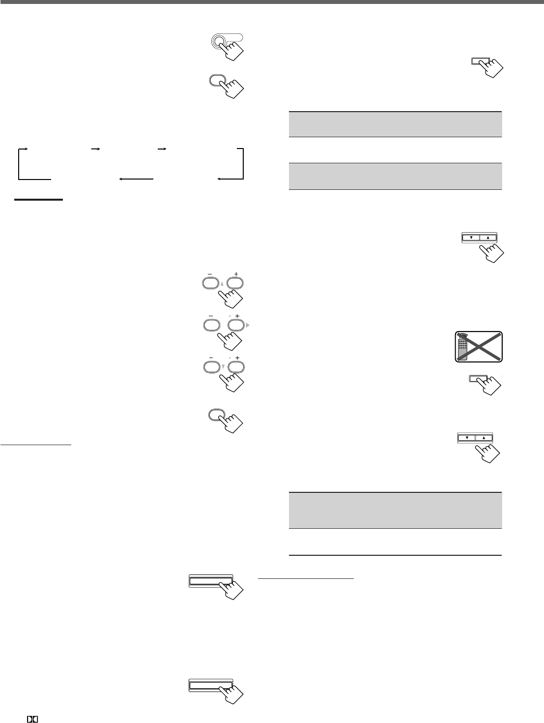
22
3
Press SOUND.
10 keys are activated for sound adjustments.
4
Press TEST to check if you can hear the
sounds through all the speakers at the
equal level.
“TEST TONE L” starts flashing on the
display, and a test tone comes out of the
speakers in the following order:
Notes:
•You can adjust the speaker output levels without outputting the
test tone.
•No test tone comes out of the center speaker when “CNTR SP”
is set to “NONE.”
•No test tone comes out of the rear speakers when “REAR SP”
is set to “NONE.”
5
Adjust the speaker output levels
(–10 to +10).
Adjust the center speakers and rear speakers levels
by comparing with the sound from the front
speakers.
•To adjust the center speaker level, press
CENTER +/–.
•To adjust the left rear speaker level, press
REAR•L +/–.
•To adjust the right rear speaker level, press
REAR•R +/–.
6
Press TEST again to stop the test
tone.
On the front panel:
You can also use the buttons on the front panel to adjust the
Surround modes. However, no test tone is available when using the
buttons on the front panel. So, make adjustments while listening to
the sound of the source played back.
1
Set the analog or digital input mode for the
source you like to listen and start playing.
When playing back software encoded with Dolby Digital and
DTS Digital Surround, select the digital input mode (see page
11).
2
Press SURROUND ON/OFF
repeatedly to activate Surround
mode.
Each time you press the button, Surround mode turns on and off
alternately.
•If you are playing back software encoded with Dolby Digital
multichannel, “DOLBY DIGITAL” is selected.
•If you are playing back software encoded with DTS Digital
Surround, “DTS SURROUND” is selected.
•If you are playing back any software other
than above, you can select “PL II MUSIC”
or “PL II MOVIE” according to the source
by pressing SURROUND MODE.
( PRO LOGIC II indicator lights up on the display.)
If you like to adjust sound, go to step
3
.
3
Adjust the speaker output levels.
1)
Press ADJUST repeatedly until one
of the following indications (with the
current setting)* appears on the
display.
CENTER :To adjust the center speaker output level
(–10 to +10).
REAR L : To adjust the left rear speaker output level
(–10 to +10).
REAR R : To adjust the right rear speaker output level
(–10 to +10).
*“0” is the initial setting. If you have already changed the
setting, another number (level) will be shown.
2)
Press CONTROL UP 5/
DOWN ∞ to adjust the selected
speaker output levels.
3)
Repeat steps
1)
and
2)
to adjust the other
speaker levels.
When you select “PL II MUSIC,” you can go to the
following adjustment.
4
Turn on Panorama control on or off.
1)
Press ADJUST repeatedly until
“PANORAMA” (with the current
setting)* appears on the display.
*“OFF” is the initial setting. If you have
already changed the setting, “ON” will be shown.
2)
Press CONTROL UP 5/DOWN ∞
to select if you turn on or off
Panorama control.
•Each time you press the button, “ON” and
“OFF” change alternately.
ON : Select this when you like to enjoy
“wraparound” sound effect with side-wall
image.
OFF : Select this when you like to enjoy originally
recorded sounds.
To cancel Surround mode
Press SURROUND ON/OFF again so that “SURROUND OFF”
appears on the display.
•If Surround mode is canceled while playing back multichannel
digital software, all channel signals are mixed and output through
the front speakers (and subwoofer if you have connected a
subwoofer and set the subwoofer setting correctly—“YES”).
Creating Realistic Sound Fields
TEST
1
SOUND
TEST TONE L
(Left front speaker)
TEST TONE LS
(Left rear speaker)
TEST TONE RS
(Right rear speaker)
TEST TONE C
(Center speaker)
TEST TONE R
(Right front speaker)
SURROUND MODE
TEST
1
CENTER
23
REAR R
89
REAR L
56
ADJUST
CONTROL
DOWN UP
CONTROL
DOWN UP
ADJUST
Remote
NOT
SURROUND ON/OFF
EN18-23.RX-6020V[J]_f 01.12.7, 11:34 AM22
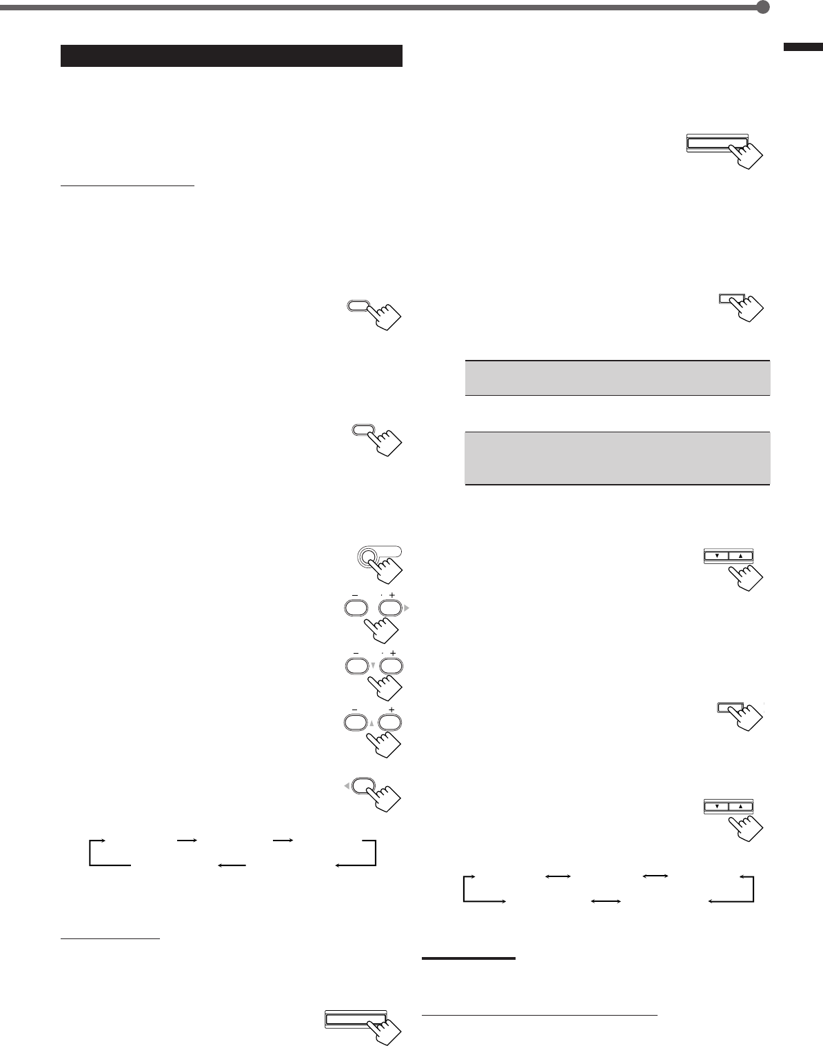
23
Creating Realistic Sound Fields
ADJUST
SURROUND MODE
CONTROL
DOWN UP
EFFECT 1 EFFECT 2 EFFECT 3
EFFECT 4
EFFECT 5
ADJUST
CONTROL
DOWN UP
SURROUND
ON/OFF
SURROUND
MODE
EFFECT 1 EFFECT 2 EFFECT 3
EFFECT 4
EFFECT 5
REAR R
89
REAR L
56
CENTER
23
SOUND
Using DAP Modes and All Channel Stereo
Once you have adjusted the DAP modes and All Channel Stereo, the
adjustment is memorized for each source.
•You cannot use the DAP modes and All Channel Stereo if no rear
speakers are connected and activated.
•You cannot adjust the effect level for All Channel Stereo.
From the remote control:
It will be convenient for you to use the remote control for
adjustments, since you can make adjustments from your listening
point.
1
Start playing 2 channel software—either analog
or Linear PCM—and select the source.
2
Press SURROUND ON/OFF to activate
Surround mode.
When Surround mode turns on, the last selected Surround mode
will be activated.
•Each time you press the button, Surround mode turns on and
off alternately.
3
Press SURROUND MODE repeatedly
until one of the DAP modes—“LIVE
CLUB,” “DANCE CLUB,” “HALL,”
“PAVILION”—or “ALL CH STEREO”
appears on the display.
The DSP indicator also lights up on the display.
If you like to adjust sound, go to step
4
.
4
Press SOUND.
10 keys are activated for sound adjustments.
5
Adjust the speakers output levels
(–10 to +10).
•To adjust the left rear speaker level, press
REAR•L +/–.
•To adjust the right rear speaker level, press
REAR•R +/–.
For “ALL CH STEREO” only:
•To adjust the center speaker level, press
CENTER +/–.
6
For DAP modes only:
Press EFFECT to select the effect level
(1 to 5) you want.
•Each time you press the button, the effect
level changes as follows:
As the number increases, the selected mode becomes stronger
(normally set it to “EFFECT 3”).
On the front panel:
1
Start playing 2 channel software—either analog
or Linear PCM—and select the source.
2
Press SURROUND ON/OFF to
activate Surround mode.
When Surround mode turns on, the last selected Surround mode
will be activated.
•Each time you press the button, Surround mode turns on and off
alternately.
3
Press SURROUND MODE
repeatedly until one of the DAP
modes—“LIVE CLUB,” “DANCE
CLUB,” “HALL,” “PAVILION,”—
or “ALL CH STEREO” appears on the display.
The DSP indicator also lights up on the display.
If you like to adjust sound, go to step
4
.
4
Adjust the speaker output levels.
1)
Press ADJUST repeatedly until one
of the following indications (with the
current setting)* appears on the
display.
REAR L : To adjust the left rear speaker output level
(–10 to +10).
REAR R : To adjust the right rear speaker output level
(–10 to +10).
CENTER : For “ALL CH STEREO” only—to adjust the
center speaker output level
(–10 to +10).
* “0” is the initial setting. If you have already changed the
setting, another number (level) will be shown.
2)
Press CONTROL UP 5/DOWN ∞
to adjust the selected speaker
output levels.
3)
Repeat steps
1)
and
2)
to adjust the
other speaker levels.
5
Only for DAP modes:
Adjust the DSP effect level.
1)
Press ADJUST repeatedly until
“EFFECT” (with the current
setting)* appears on the display.
*“EFFECT 3” is the initial setting. If you have already
changed the setting, another setting will be shown.
2)
Press CONTROL UP 5/DOWN ∞
to select the effect level (1 to 5) you
want.
•Each time you press the button, the effect
level changes as follows:
As the number increases, the selected mode becomes
stronger (normally set it to “EFFECT 3”).
Note:
You cannot select any DAP mode and All Channel Stereo for Dolby
Digital and DTS Digital Surround.
To cancel DAP modes and All Channel Stereo
Press SURROUND ON/OFF so that “SURROUND OFF” appears on
the display. The DSP indicator goes off.
SURROUND ON/OFF
EFFECT
4
EN18-23.RX-6020V[J]_f 01.12.7, 11:34 AM23
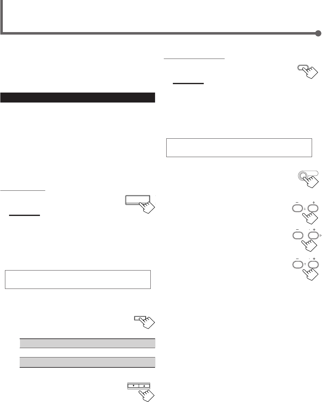
24
From the remote control:
1
Press DVD MULTI.
Note:
When you select “DVD MULTI” as the source to play, Surround
mode is canceled, and the SURROUND ON/OFF and
SURROUND MODE buttons do not work.
2
Select the analog discrete output mode on the
DVD player, and start playing a DVD.
•Refer to the manual supplied with the DVD player.
If you need to make any adjustment, go to the
following steps.
3
Press SOUND.
10 keys are activated for adjusting the sound.
4
Adjust the speaker output levels.
•To adjust the center speaker level, press
CENTER +/– (–10 to +10).
•To adjust the left rear speaker level, press
REAR•L +/– (–10 to +10).
•To adjust the right rear speaker level, press
REAR•R +/– (–10 to +10).
Using DVD MULTI Playback Mode
DVD MULTI
This receiver provides DVD MULTI Playback Mode for
reproducing the analog discrete output mode of the DVD player.
Before playing back a DVD, refer also to the manual supplied with
your DVD player.
Activating DVD MULTI Playback Mode
You can adjust DVD MULTI Playback Mode while playing back a
DVD with analog discrete output mode on a DVD player.
Once you have made adjustments, the receiver memorizes the
adjustments until you change them.
You also need to set the DVD player to the analog discrete output
mode.
Before you start, remember...
There is a time limit in doing the following steps. If the setting is
canceled before you finish, start from step
3
again.
On the front panel:
1
Press DVD MULTI.
Note:
When you select “DVD MULTI” as the source to play, Surround
mode is canceled, and the SURROUND ON/OFF and
SURROUND MODE buttons do not work.
2
Select the analog discrete output mode on the
DVD player, and start playing a DVD.
•Refer also to the manual supplied with the DVD player.
If you need to make any adjustment, go to the
following steps.
3
Adjust the speaker output levels.
1)
Press ADJUST repeatedly until one
of the following indications appears
on the display.
CENTER : To adjust the center speaker level.
REAR L : To adjust the left rear speaker level.
REAR R : To adjust the right rear speaker level.
2)
Press CONTROL UP 5/DOWN ∞
to adjust the selected speaker
output levels (–10 to +10).
3)
Repeat steps
1)
and
2)
to adjust the other
speaker output levels.
REAR R
89
CENTER
23
SOUND
CONTROL
DOWN UP
ADJUST
REAR L
56
DVD MULTI
EN24-32.RX-6020V[J]_f 01.12.7, 11:34 AM24
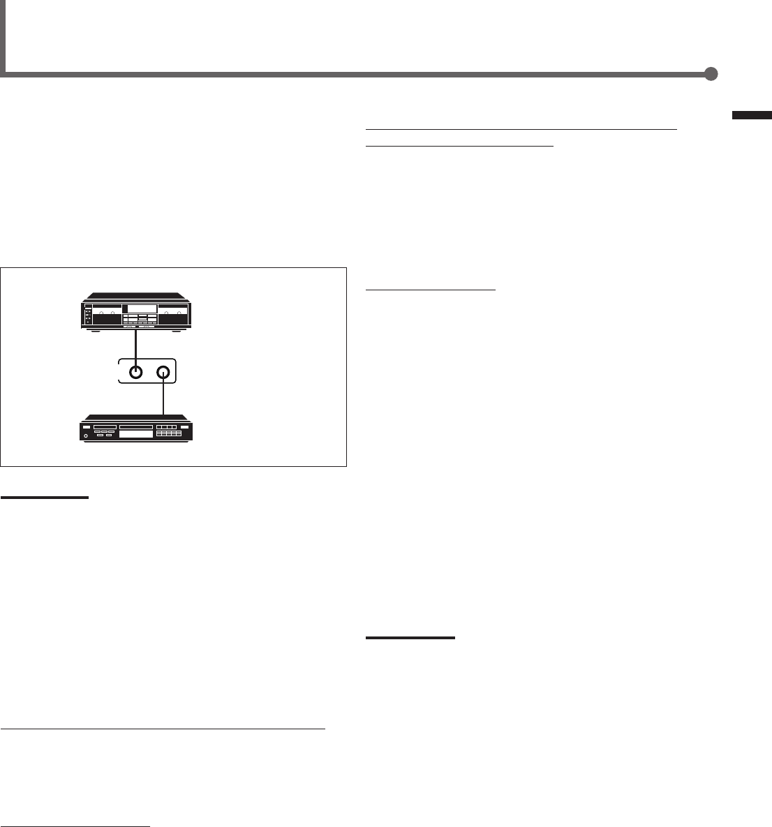
25
COMPU LINK-4
(SYNCHRO)
Cassette deck
or
CD recorder
CD player
The COMPU LINK remote control system allows you to operate
JVC’s audio components through the remote sensor on the receiver.
To use this remote control system, you need to connect JVC’s audio
components through the COMPU LINK–4 (SYNCHRO) jacks (see
below) in addition to the connections using cables with RCA pin
plugs (see page 6).
•Make sure that the AC power cords of these components are
unplugged before making connection. Plug the AC power cords
only after all connections are completed.
Notes:
•There are four versions of COMPU LINK remote control system.
This receiver is equipped with the fourth version—COMPU LINK-4.
This version is added systematic operations with the CD recorder
to the previous version—COMPU LINK-3.
•If your audio component has two COMPU LINK jacks, you can use
either one. If it has only one COMPU LINK jack, connect it so that it
is the last item in the series of components.
•To operate the cassette deck or CD recorder using the COMPU
LINK remote control system, set the source name correctly.
(See page 8.)
•Refer also to the manuals supplied with your audio components.
This remote control system allows you to use four functions listed
below.
Remote Control through the Remote Sensor on the Receiver
You can control the connected audio components through the
remote sensor on the receiver using this remote control. Aim the
remote control directly at the remote sensor on the receiver. For
details, see pages 28 and 29.
Automatic Source Selection
When you press the play (33
33
3) button on a connected component or
on its own remote control, the receiver automatically turns on and
changes the source to the component. On the other hand, if you
select a new source on the receiver or on the remote control, the
selected component begins playing immediately.
In both cases, the previously selected source continues playing
without sound for a few seconds.
Automatic Power On/Off (Standby): Only possible with the
COMPU LINK-3 and COMPU LINK-4
Both the CD player and cassette deck (or CD recorder) turn on and
off (standby) along with the receiver.
When you turn on the receiver, the CD player or cassette deck (or
CD recorder) will turn on automatically, depending on which
component has been previously selected.
When you turn off the receiver, both the CD player and cassette
deck (or CD recorder) will turn off (standby).
Synchronized Recording
Synchronized recording means the cassette deck starts recording as
soon as a CD begins playing.
To use synchronized recording, follow these steps:
1
Put a tape in the cassette deck and a disc in the
CD player.
2
Press the record (¶) button and the pause (8)
button on the cassette deck at the same time.
This puts the cassette deck into recording pause.
If you do not press the record (¶) button and pause (8) button at
the same time, the synchronized recording feature will not
operate.
3
Press the play (3) button on the CD player.
The source changes on the receiver, and as soon as play starts,
the cassette deck starts recording. When the play ends, the
cassette deck enters recording pause, and stops about 4 seconds
later.
Notes:
•During synchronized recording, the selected source cannot be
changed.
•If the power of any component is shut off during synchronized
recording, the COMPU LINK remote control system may not
operate properly. In this case, you must start again from the
beginning.
COMPU LINK Remote Control System
Using DVD MULTI Playback Mode / COMPU LINK Remote Control System
EN24-32.RX-6020V[J]_f 01.12.7, 11:34 AM25
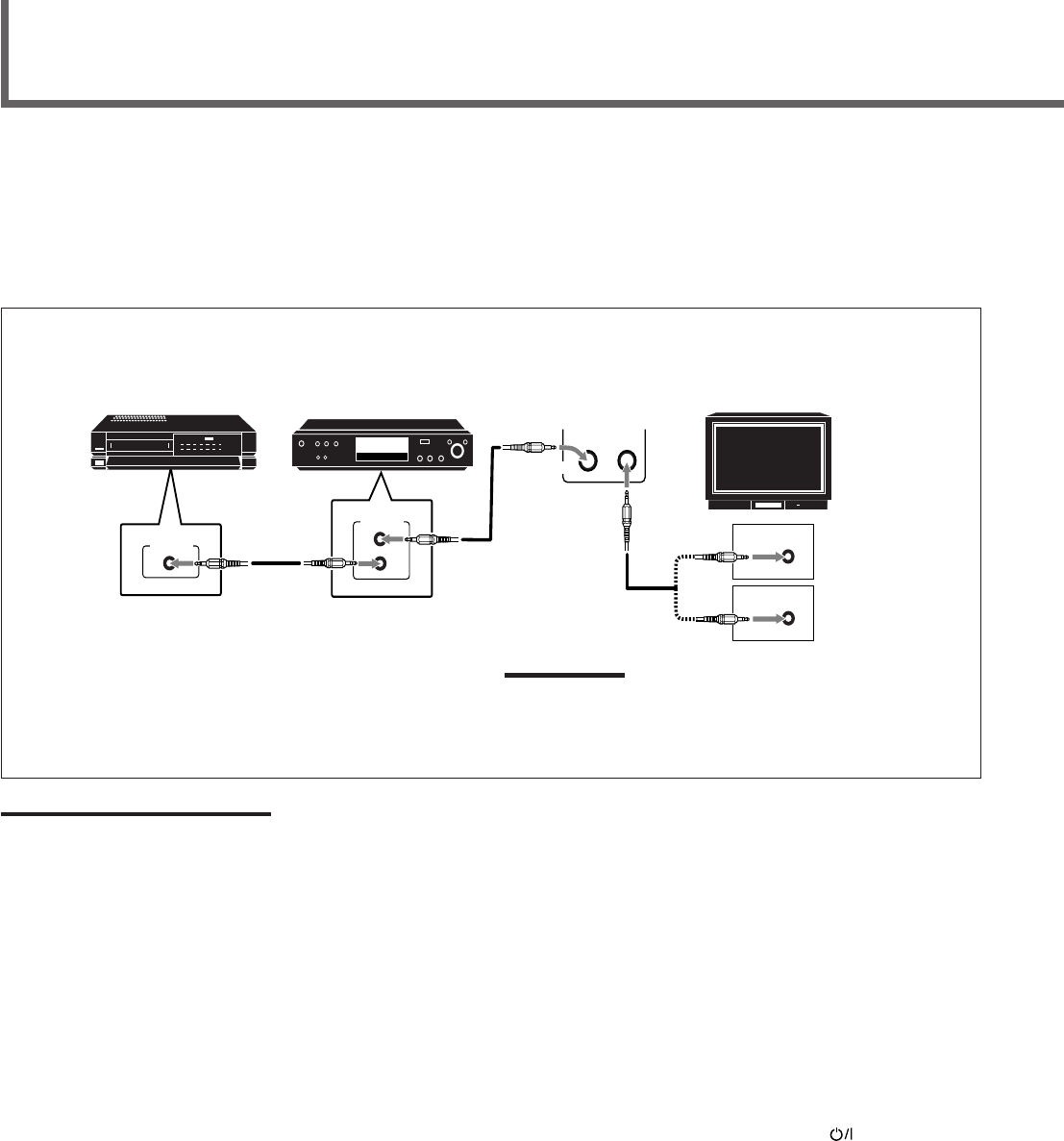
26
The AV COMPU LINK remote control system allows you to operate JVC’s audio components through the remote sensor on the receiver.
To use this remote control system, you need to connect the video components you want to operate by following the diagram and the
procedure below.
•Make sure that AC power cords of these components are unplugged before connecting. Plug AC power cords only after all connections are
completed.
CONNECTIONS:
AV COMPU LINK Remote Control System
AV
COMPU LINK
AV
COMPU LINK
VHS
AV
COMPU LINK
DVD
AV
COMPU LINK EX
AV
COMPU LINK III
VCR DVD player TV
Note:
You can only connect to the TV with the AV COMPU LINK EX or AV
COMPU LINK III terminal.
The TV with AV COMPU LINK RECEIVER/AMP terminal will not be
used.
Notes:
•When connecting only the VCR and DVD player to this receiver, use the cable with monaural mini-plugs.
•You can connect only the TV with AV COMPU LINK to the AV COMPU LINK terminal.
•Refer also to the manuals supplied with your video components.
•Make sure that the remote control code of the VCR connected to the VCR jacks is set to code “A.”
1
Unplug your VCR, DVD player, TV, and this
receiver from the AC outlets.
2
Connect your VCR, DVD player, TV, and this
receiver using cables with the monaural mini-
plugs (not supplied).
•See “CONNECTIONS” above.
3
Connect VCR, DVD player, TV, and this receiver
using cables with RCA pin plug.
•See pages 6 and 7.
4
Plug AC power cords of the components back into
the AC outlets.
5
When turning on the TV for the first time after
the AV COMPU LINK connection, turn the TV
volume to the minimum with the volume control
on the TV.
6
Turn on the other connected components first,
then turn on this receiver.
•When turning on the VCR, use the remote control supplied
with this receiver (press STANDBY/ON VCR).
EN24-32.RX-6020V[J]_f 01.12.7, 11:34 AM26

27
AV COMPU LINK Remote Control System
Automatic Selection of TV’s Input Mode
•When you select “TV SOUND” (or “TV DIGITAL”) as the source
to play on the receiver, the TV automatically changes the input
mode to the TV tuner so that you can watch TV.
•When you select “DVD” (or “DVD DIGITAL”), “DVD MULTI,”
or “VCR” as the source to play on the receiver, the TV
automatically changes the input mode to the appropriate position
(either Video Input 1 or Video Input 2) so that you can view the
playback picture.
Automatic Power On/Off
The TV, VCR, and DVD player turn on and off along with the
receiver.
When you turn on the receiver;
•If the previously selected source is “VCR,” the TV and VCR will
turn on automatically.
•If the previously selected source is “TV SOUND” (or “TV
DIGITAL”), only the TV will turn on automatically.
•If the previously selected source is “DVD” (or “DVD DIGITAL”)
or “DVD MULTI,” the TV and DVD player will turn on
automatically.
When you turn off the receiver, the TV, VCR and the DVD player
will turn off.
Note:
Even if you turn off the receiver while recording on the VCR, the VCR
will not turn off and continues recording.
The AV COMPU LINK remote control system allows you to use
five basic functions listed below.
Remote Control of the TV, DVD player, and VCR Using This
Remote Control
•Aim the remote control directly at the remote sensor on each
component (see page 29 for details).
One-Touch Video Play
Simply by inserting a video cassette without its safety tab into the
VCR, you can enjoy the video playback without setting other
switches manually. The receiver automatically turns on and changes
the source to “VCR.”
The TV automatically turns on and changes the input mode to the
appropriate position so that you can view the playback picture.
When you insert a video cassette with its safety tab, press the play
(33
33
3) button on the VCR or on the remote control. You can get the
same result.
One Touch DVD Play
Simply by starting playback on the DVD player, you can enjoy the
DVD playback without setting other switches manually.
•When DVD player is connected through the analog input jacks on
this receiver (and analog input is selected), the receiver
automatically turns on and changes the source to “DVD” or “DVD
MULTI.”
•When the DVD player is connected through the digital input
terminal on this receiver (and digital input is selected), the
receiver automatically turns on and changes the source to “DVD
DIGITAL.”
The TV automatically turns on and changes the input mode to the
position so that you can view the playback picture.
EN24-32.RX-6020V[J]_f 01.12.7, 11:34 AM27

28
Operating JVC’s Audio/Video Components
You can use the remote control to operate other JVC’s
components.
Operating Audio Components
IMPORTANT:
To operate JVC’s audio components using this remote control:
•You need to connect JVC’s audio components through the COMPU
LINK (SYNCHRO) jacks (see page 25) in addition to the
connections using cables with RCA pin plugs (see page 6).
•Aim the remote control directly at the remote sensor on the receiver.
•If you use the buttons on the front panel, the remote control will not
operate that source. To operate a source with the remote control,
the source must be selected with source selecting buttons on the
remote control.
•To operate the cassette deck or CD recorder by COMPU LINK
remote control system, set the source name correctly. (See page 8.)
•Refer also to the manuals supplied with your audio components.
Sound Adjustment
You can always use following buttons for sound adjustment:
SURROUND ON/OFF : Turn on or off Surround modes.
SURROUND MODE : Select Surround modes.
After pressing SOUND, you can use following buttons for sound
adjustment:
SUBWOOFER +/–: Adjust the subwoofer output level.
CENTER +/–: Adjust the center speaker output level.
REAR•L +/–: Adjust the left rear speaker output level.
REAR•R +/–: Adjust the right rear speaker output level.
EFFECT : Select the DAP effect level.
TEST : Turn on or off the test tone output.
Note:
After adjusting sounds, press the corresponding source selecting
button or CD-DISC to operate your target source with 10 keys on the
remote control, otherwise 10 keys cannot be used for operating your
target source.
Tuner
You can always use following buttons:
FM/AM : Alternate between FM and AM.
FM MODE : Change the FM reception mode.
After pressing FM/AM, you can use following buttons for Tuner
operations:
1 – 10, +10 : Select a preset channel number directly.
•For channel number 5, press 5.
•For channel number 15, press +10, then 5.
•For channel number 20, press +10, then 10.
CD player
After pressing CD, you can use following buttons for CD operations:
33
33
3: Start playback.
4: Return to the beginning of the current
(or previous) track.
¢: Skip to the beginning of the next track.
77
77
7: Stop playback.
88
88
8: Pause playback. To release it, press 33
33
3.
1 – 10, +10 : Select a track number directly.
•For track number 5, press 5.
•For track number 15, press +10, then 5.
•For track number 20, press +10, then 10.
CD changer
After pressing CD-DISC, you can use following buttons for CD
changer operations:
33
33
3: Start playback.
4: Return to the beginning of the current
(or previous) track.
¢: Skip to the beginning of the next track.
77
77
7: Stop playback.
88
88
8: Pause playback. To release it, press 33
33
3.
1 – 6, 7/P : Select the number of a disc installed in a CD
changer.
If your CD changer is of 200-disc loading capability (except for
XL-MC100 and XL-MC301),
you can do following operations with number buttons after pressing
CD:
1
Select a disc number.
2
Then select a track number (always enter two digits).
3
Start playback.
Examples:
•Selecting disc number 3, track number 2, and start playback.
Press 3, then, 0, 2, then 3.
•Selecting disc number 10, track number 5, and start playback.
Press 1, 0, then, 0, 5, then 3.
•Selecting disc number 105, track number 12, and start playback.
Press 1, 0, 5, then 1, 2, then 3.
CD recorder
Before starting operations described below, make sure that you have
changed the source name correctly. See page 8.
After pressing TAPE/CDR, you can use following buttons for CD
recorder operations:
33
33
3: Start playback.
4: Return to the beginning of the current
(or previous) track.
¢: Skip to the beginning of the next track.
77
77
7: Stop playback or recording.
88
88
8: Pause playback. To release it, press 33
33
3.
REC PAUSE : Press this button to enter recording pause.
Press this button and then 33
33
3 to start recording.
EN24-32.RX-6020V[J]_f 01.12.7, 11:34 AM28
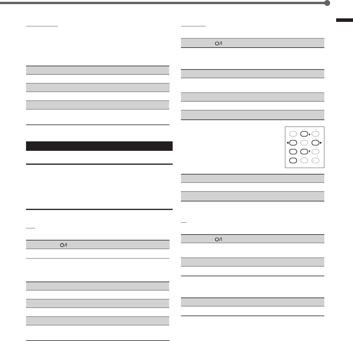
29
Operating JVC's Audio / Video Components
TEST
EFFECT
MENU
ENTER
CENTER
REAR L
SUBWOOFER
REAR R
1
4
7/P
10
2
5
8
0
3
6
9
10
100
RETURN
DVD player
You can always perform following operations:
STANDBY/ON DVD : Turn on or off a DVD player.
After pressing DVD or DVD MULTI, you can use following buttons
for DVD player operations:
33
33
3: Start playback.
4: Return to the beginning of the current
(or previous) track.
¢: Skip to the beginning of the next track.
77
77
7: Stop playback.
88
88
8: Pause playback. To release it, press 33
33
3.
DVD menu operations
After pressing DVD or DVD MULTI, you can
use following buttons for DVD menu
operations:
MENU : Display or erase the menu screen.
55
55
5/∞∞
∞∞
∞/33
33
3/22
22
2: Select an item on the menu screen.
ENTER : Enter a selected item.
TV
You can always perform following operations:
STANDBY/ON TV : Turn on or off a TV.
TV/VIDEO : Change the input mode (TV tuner and video
input).
TV VOLUME +/–: Adjust the volume.
TV CH +/–: Change the channels.
After pressing TV SOUND, you can use following buttons for TV
operations:
1 – 9, 0, 100+ (+10) :Select a channel.
RETURN (10) :Function as the RETURN button.
Cassette deck
Before starting operations described below, make sure that you have
changed the source name correctly. See page 8.
After pressing TAPE/CDR, you can use following buttons for
cassette deck operations:
33
33
3: Start playback.
FF : Fast wind the tape from left to right.
REW : Fast wind the tape from right to left.
77
77
7: Stop playback or recording.
88
88
8: Pause playback. To release it, press 33
33
3.
REC PAUSE : Press this button to enter recording pause.
Press this button and then 33
33
3 to start recording.
Operating Video Components
IMPORTANT:
To operate JVC’s video components using this remote control:
•Some JVC’s VCRs can accept two types of the control signals—
remote code “A” and “B.” Before using this remote control, make
sure that the remote control code of the VCR connected to the VCR
jacks is set to code “A.”
•Aim the remote control directly at the remote sensor on each
component, not on the receiver.
VCR
You can always perform following operations:
STANDBY/ON VCR :Turn on or off a VCR.
VCR CH +/–:Change the TV channels on the VCR.
After pressing VCR (source selecting button), you can use following
buttons for VCR operations:
33
33
3: Start playback.
FF : Fast wind a tape.
REW : Rewind a tape.
77
77
7: Stop playback or recording.
88
88
8: Pause playback. To release it, press 33
33
3.
REC PAUSE : Press this button to enter recording pause.
Press this button and then 33
33
3 to start recording.
EN24-32.RX-6020V[J]_f 01.12.7, 11:34 AM29
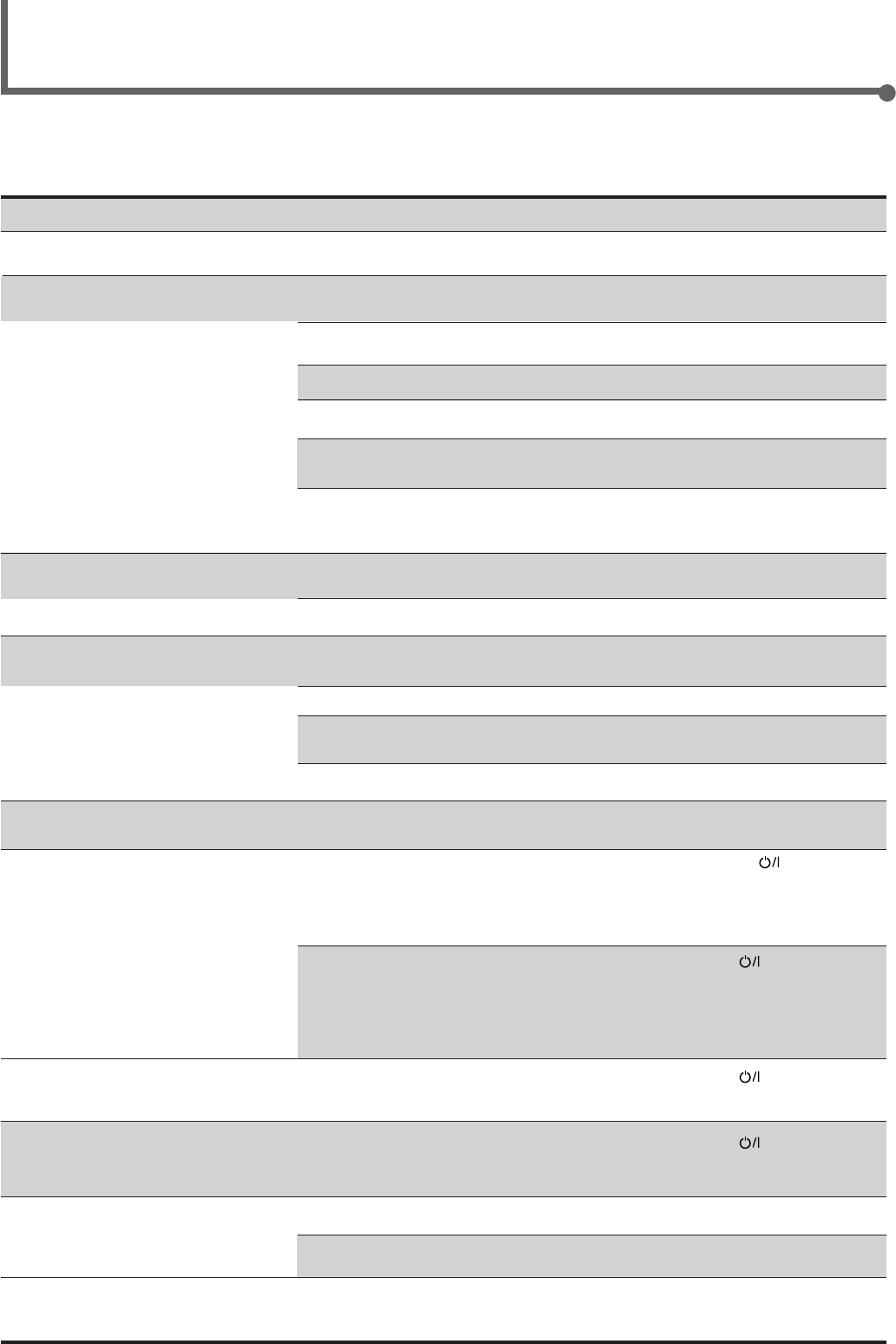
30
SOLUTION
Plug the power cord into an AC outlet.
Check speaker wiring and reconnect if
necessary.
Press SPEAKERS ON/OFF button correctly.
Select the correct source.
Press MUTING to cancel the mute.
Select the correct input mode (analog or
digital).
Check connections.
For analog connections, see page 6.
For digital connections, see page 7.
Check speaker wiring and reconnect if
necessary.
Adjust the balance properly (see page 15).
Connect an outdoor FM antenna or contact
your dealer.
Select a new station.
Check with your dealer to be sure you have the
correct antenna.
Check connections.
Move the antenna farther from automobile
traffic.
1. Press STANDBY/ON on the front
panel to turn off the receiver.
2. Stop the playback source.
3. Turn on the receiver again, and adjust the
volume.
Press STANDBY/ON on the front panel,
then check the speaker wiring.
If “OVERLOAD” does not disappear, unplug
the AC power cord, then plug it back again.
If speaker wiring is not short-circuited, contact
your dealer.
Press STANDBY/ON on the front panel to
turn off the receiver. After unplugging the
power cord, consult your dealer.
Press STANDBY/ON on the front panel to
turn off the receiver. After unplugging the
power cord, consult your dealer.
Remove the obstruction.
Replace batteries.
Select the correct remote control operation
mode (see pages 28 and 29).
POSSIBLE CAUSE
The power cord is not plugged in.
Speaker signal cables are not connected.
The SPEAKERS ON/OFF button is not
set correctly.
An incorrect source is selected.
Muting is activated.
An incorrect input mode (analog or
digital) is selected.
Connections are incorrect.
Speaker signal cables are not connected
properly.
The balance is set to one extreme.
Incoming signal is too weak.
The station is too far away.
An incorrect antenna is used.
Antennas are not connected properly.
Ignition noise from automobiles.
Speakers are overloaded because of high
volume.
Speakers are overloaded because of short
circuit of speaker terminals.
The built-in microcomputer is not
functioning correctly.
The receiver is overloaded because of a
high voltage.
There is an obstruction in front of the
remote sensor on the receiver.
Batteries are weak.
An incorrect remote control operation
mode is selected.
Troubleshooting
Use this chart to help you solving daily operational problems. If there is any problem you cannot solve, contact your JVC service center.
PROBLEM
The power does not turn on.
No sound from speakers.
Sound from one speaker only.
Continuous hiss or buzzing during FM
reception.
Occasional cracking noise during FM
reception.
“OVERLOAD” starts flashing on the
display.
“DSP MICON NG” starts flashing on the
display.
The STANDBY lamp lights up after
turning on the power, but soon the
receiver turns off (into standby mode).
Remote control does not work.
Remote control does not work for the
source (or other components) you try to
operate.
EN24-32.RX-6020V[J]_f 01.12.7, 11:34 AM30

31
Trouble Shooting / Specifications
Specifications Designs & specifications are subject to change without notice.
Amplifier
Output Power
At Stereo operation:
Front channels: 100 W per channel, min. RMS, driven into 8 Ω,
40 Hz to 20 kHz with no more than 0.8% total
harmonic distortion.
At Surround operation:
Front channels: 100 W per channel, min. RMS, driven into 8 Ω at 1 kHz with no
more than 0.8% total harmonic distortion.
Center channel: 100 W, min. RMS, driven into 8 Ω at 1 kHz, with no more than
0.8% total harmonic distortion.
Rear channels: 100 W per channel, min. RMS, driven into 8 Ω at 1 kHz, with no
more than 0.8% total harmonic distortion.
Audio
Audio Input Sensitivity/Impedance (1 kHz): DVD, VCR, TV SOUND, CD, TAPE/CDR:
220 mV/47 k Ω
Audio Input (DIGITAL IN)* : Coaxial: DIGITAL 1 (DVD): 0.5 V (p-p)/75 Ω
Optical: DIGITAL 2 (CD): –21 dBm to –15 dBm (660 nm ±30 nm)
* Corresponds to Linear PCM, Dolby Digital, and DTS Digital Surround
(with sampling frequency — 32 kHz, 44.1 kHz, 48 kHz).
Audio Output Level: TAPE/CDR, VCR: 220 mV
Signal-to-Noise Ratio (’66 IHF/’78 IHF): DVD, VCR, TV SOUND, CD, TAPE/CDR:
87 dB/78 dB
Frequency Response (8 Ω): DVD, VCR, TV SOUND, CD, TAPE/CDR:
20 Hz to 20 kHz (±1 dB)
Tone Control: Bass (100 Hz): ±10 dB
Treble (10 kHz): ±10 dB
Video
Video Input Sensitivity/Impedance:
Composite video: VCR, DVD: 1 V (p-p)/75 Ω
Video Output Level/Impedance:
Composite video: VCR, MONITOR OUT: 1 V (p-p)/75 Ω
Synchronization: Negative
Signal-to-Noise Ratio: 45 dB
EN24-32.RX-6020V[J]_f 01.12.7, 11:34 AM31

32
FM tuner (IHF)
Tuning Range: 87.5 MHz to 108.0 MHz
Usable Sensitivity: Monaural: 12.8 dBf (1.2 µV/75 Ω)
50 dB Quieting Sensitivity: Monaural: 21.3 dBf (3.2 µV/75 Ω)
Stereo: 41.3 dBf (31.5 µV/75 Ω)
Signal-to-Noise Ratio (IHF-A weighted): Monaural: 78 dB at 85 dBf
Stereo: 73 dB at 85 dBf
Total Harmonic Distortion: Monaural: 0.4% at 1 kHz
Stereo: 0.6% at 1 kHz
Stereo Separation at REC OUT: 35 dB at 1 kHz
Alternate Channel Selectivity: 45 dB: (±400 kHz)
Frequency Response: 30 Hz to 15 kHz: (+0.5 dB, –3 dB)
AM tuner
Tuning Range: 530 kHz to 1 710 kHz
Usable Sensitivity: Loop antenna 400 µV/m
Signal-to-Noise Ratio: 50 dB (100 mV/m)
General
Power Requirements: AC 120V , 60 Hz
Power Consumption: 180 W/230 VA (at operation)
2 W (in standby mode)
Dimensions (W x H x D): 435 mm x 146.5 mm x 416 mm
(17 3/16 in. x 5 13/16 in. x 16 7/16 in.)
Mass: 8.8 kg (19.5 lbs)
Specifications
EN24-32.RX-6020V[J]_f 01.12.7, 11:34 AM32

BT-51002-5
(0301)
QUALITY SERVICE
HOW TO LOCATE YOUR JVC SERVICE CENTER
Dear Customer,
In order to receive the most satisfaction from your purchase,please read the instruction booklet before
operating the unit.In the event that repairs are necessary, please call 1 (800)537-5722 for your nearest
authorized servicer or visit our website at www.JVC.com
Remember to retain your Bill of Sale for Warranty Service.
Do not service the television yourself
Caution
To prevent electrical shock,do not open the cabinet.There are no user serviceable
parts inside.Please refer to qualified service personnel for repairs.
Accessories
To purchase accessories for your JVC product,please call toll free:1 (800)882-2345 or
on the web at www.JVC.com
TOLL FREE: 1 (800) 537-5722
http://www.jvc.com
Authorized Service Centers
®
RX-6020VBK[J]_Warranty_f 01.12.7, 11:34 AM2
THIS LIMITED WARRANTY IS VALID ONLY IN THE FIFTY (50) UNITED STATES, THE DISTRICT OF COLUMBIA AND
IN COMMONWEALTH OF PUERTO RICO.
WHAT WE WILL DO:
If this product is found to be defective, JVC will repair or replace defective parts at no charge to the original owner.
Such repair and replacement services shall be rendered by JVC during normal business hours at JVC authorized service
centers. Parts used for replacement are warranted only for the remainder of the Warranty Period. All products and parts
thereof may be brought to a JVC authorized service center on a carry-in basis except for Television sets having a screen
size 25 inches and above which are covered on an in-home basis.
WHAT YOU MUST DO FOR WARRANTY SERVICE:
Return your product to a JVC authorized service center with a copy of your bill of sale. For your nearest JVC authorized
service center, please call toll free: (800) 537-5722.
If service is not available locally, box the product carefully, preferably in the original carton, and ship, insured, with
a copy of your bill of sale plus a letter of explanation of the problem to the nearest JVC Factory Service Center, the
name and location of which will be given to you by the toll-free number.
If you have any questions concerning your JVC Product, please contact our Customer Relations Department.
WHAT IS NOT COVERED:
This limited warranty provided by JVC does not cover:
1. Products which have been subject to abuse, accident, alteration, modification, tampering, negligence, misuse, faulty
installation, lack of reasonable care, or if repaired or serviced by anyone other than a service facility authorized by
JVC to render such service, or if affixed to any attachment not provided with the products, or if the model number
or serial number has been altered, tampered with, defaced or removed;
2. Initial installation and installation and removal for repair;
3. Operational adjustments covered in the Owner's Manual, normal maintenance, video and audio head cleaning;
4. Damage that occurs in shipment, due to act of God, and cosmetic damage;
5. Signal reception problems and failures due to line power surge;
6. Video Pick-up Tubes/CCD Image Sensor, Cartridge, Stylus (Needle) are covered for 90 days from the date of purchase;
7. Batteries (except that Rechargeable Batteries are covered for 90 days from the date of purchase);
There are no express warranties except as listed above.
THE DURATION OF ANY IMPLIED WARRANTIES, INCLUDING THE IMPLIED WARRANTY OF MERCHANTABILITY, IS
LIMITED TO THE DURATION OF THE EXPRESS WARRANTY HEREIN.
JVC SHALL NOT BE LIABLE FOR THE LOSS OF USE OF THE PRODUCT, INCONVENIENCE, LOSS OR ANY OTHER
DAMAGES, WHETHER DIRECT, INCIDENTAL OR CONSEQUENTIAL (INCLUDING, WITHOUT LIMITATION, DAMAGE
TO TAPES, RECORDS OR DISCS) RESULTING FROM THE USE OF THIS PRODUCT, OR ARISING OUT OF ANY BREACH
OF THIS WARRANTY. ALL EXPRESS AND IMPLIED WARRANTIES, INCLUDING THE WARRANTIES OF MERCHANT-
ABILITY AND FITNESS FOR PARTICULAR PURPOSE, ARE LIMITED TO THE WARRANTY PERIOD SET FORTH ABOVE.
Some states do not allow the exclusion of incidental or consequential damages or limitations on how long an
implied warranty lasts, so these limitations or exclusions may not apply to you. This warranty gives you specific
legal rights and you may also have other rights which vary from state to state.
LIMITED WARRANTY
JVC COMPANY OF AMERICA warrants this product and all parts thereof, except as set forth below ONLY TO THE
ORIGINAL PURCHASER AT RETAIL to be FREE FROM DEFECTIVE MATERIALS AND WORKMANSHIP from the date
of original retail purchase for the period as shown below. ("The Warranty Period")
PARTS LABOR
2 YRS 2 YRS
JVC COMPANY OF AMERICA
DIVISION OF JVC AMERICAS CORP.
1700 Valley Road
Wayne, NJ 07470
REFURBISHED PRODUCTS CARRY A SEPARATE WARRANTY, THIS WARRANTY DOES NOT APPLY. FOR DETAILS OF
REFURBISHED PRODUCT WARRANTY, PLEASE REFER TO THE REFURBISHED PRODUCT WARRANTY INFORMATION
PACKAGED WITH EACH REFURBISHED PRODUCT.
For customer use:
Enter below the Model No. which is located either on the rear, bottom or side of the cabinet. Retain this information
for future reference.
Model No. : Serial No. :
Purchase data : Name of dealer :
AUDIO-2
RX-6020VBK[J]_Warranty_f 01.12.7, 11:34 AM3

VICTOR COMPANY OF JAPAN, LIMITED
EN 1201NHMMDWJEIN
J
V
C
RX-6020VBK[J]_COVER_f 01.12.7, 11:32 AM2
