Jvc Rx 884Pbk Users Manual 884P[U]COVER
RX-884PBK to the manual 03aaf0a3-8d0f-460e-a0d1-1c5bd6e2b554
2015-01-23
: Jvc Jvc-Rx-884Pbk-Users-Manual-325033 jvc-rx-884pbk-users-manual-325033 jvc pdf
Open the PDF directly: View PDF ![]() .
.
Page Count: 72
For Customer Use:
Enter below the Model No. and Serial
No. which are located either on the rear,
bottom or side of the cabinet. Retain this
information for future reference.
Model No.
Serial No.
LVT0017-001A
[U, US]
INSTRUCTIONS
MANUAL DE INSTRUCCIONES
INSTRUÇÕES
RX-884PBK
AUDIO/VIDEO CONTROL RECEIVER
RECEPTOR DE CONTROL DE AUDIO/VÍDEO
RECEPTOR DE COMANDO AUDIO/VÍDEO
RM-SR884XU REMOTE CONTROL
/DBS POWER
SOUND
CONTROL
CD
DISC
VCR1
POWER
ANALOG
/DIGITAL
AUDIO
POWER
DVD VCR1 VIDEOVCR2
CD
TV/DBS
TEST
REAR R
REAR L
SEA MODE
SUBWOOFER
TAPE/MD FM/AMPHONO
546
213
87
/P
9
0
+10
10
AUDIO/TV
/VCR
VCR1 TAPE
CONTROL
VOLUME
CHANNEL
MUTE
FF / ¢
PLAY
STOP
REC
TV/VIDEO
TV VOLUME
PAUSE
4 / REW
TV/CATV
CNTR
CNTR TONE
ENTER
MENU
EFFECT
CATV
/DBS
FM MODE/MUTE
100+
RETURN
SURROUND
MODE
O
N
S
C
R
E
E
N
C
O
N
T
R
O
L
SET EXIT
TUNING DOWN
TUNING UP
DIGITAL
–+
RX-884P AUDIO/VIDEO CONTROL RECEIVER
VIDEO
SPEAKERS
12
PHONES
DOLBY SURROUND
DSP MODE
BALANCE/SURROUND
ADJUST
SEA MODE
SEA ADJUST SETTING
MULTI JOG
MASTER VOLUME
SOURCE SELECTOR
S-VIDEO VIDEO AUDIOLR
DIGITAL INPUT FM/AM TUNNING TUNER PRESET
TUNER/SEA MEMORY FM MODE
DVD
TV SOUND/DBS PHONO
TAPE/MDVCR 1
VCR 2 FM
AM
VIDEO
CD
SOUND SELECT
INPUT ATT.
LOUDNESS ONE TOUCH OPERATION
SOURCE NAME
COMPULINK
Remote
DIGITAL
STANDBY/ON
POWER
_ ON — OFF
STANDBY
ENHANCED COMPULINK CONTROL SYSTEM
RX-884P[U]COVER 98.3.11, 5:23 PM1
Warnings, Cautions and Others / Avisos, precauciones y otras notas /
Advertêcias, precauções e outras notas /
G-1
Caution –– POWER switch and STANDBY/ON button!
This apparatus is provided with a POWER switch to be able to minimize power consumption for safe use. Therefore,
1. When doing initial setting, complete all the connections required, connect the mains plug into the wall outlet, and set the POWER
switch to ON. After these, it will be available to operate STANDBY/ON button and so on.
2. When not in use, set the POWER switch to OFF.
3. Disconnect the mains plug to shut the power off completely. The POWER switch and STANDBY/ON button in any position do
not disconnect the mains line.
4. The power can be remote controlled.
Precaución –– Interruptor POWER y botón STANDBY/ON !
Esta unidad dispone de un interruptor POWER que sirve para reducir al mínimo el consumo de alimentación para proporcionar mayor
seguridad operacional. Por lo tanto,
1. Al ejecutar el ajuste inicial, después de completar todas las conexiones requeridas, conectar el cable de alimentación a una toma de
pared, y activar el interruptor POWER. Entonces, será posible ejecutar operaciones tales como la conmutación del estado de
alimentación.
2. Desactivar el interruptor POWER al dejar la unidad fuera de uso.
3. Desconectar el cable de alimentación para desactivar la alimentación totalmente. Cualquier que sea la posición de ajustes del
interruptor POWER y el botón STANDBY/ON , la alimentación no es cortada completamente.
4. La alimentación puede ser controlada remotamente.
Precaução –– Interruptor POWER e botão STANDBY/ON !
Este aparelho dispõe de um interruptor POWER que possibilita reduzir ao mínimo o seu consumo de energia por medida de segurança.
Assim,
1. Nos ajustes iniciais, efetue todas as conexões necessárias, ligue o plugue de alimentação à tomada e coloque o interruptor POWER
em ON. Feito isso, será possível operar o botão STANDBY/ON e as diversas funções.
2. Quando não utilizar o aparelho, coloque o interruptor POWER em OFF.
3. Remova o plugue de alimentação da tomada para desligar o aparelho completamente. O interruptor POWER e o botão STANDBY/
ON , em qualquer de suas posições, não desligam a alimentação do aparelho.
4. É possível controlar remotamente a função do interruptor POWER.
CAUTION
To reduce the risk of electrical shocks, fire, etc.:
1. Do not remove screws, covers or cabinet.
2. Do not expose this appliance to rain or moisture.
PRECAUCIÓN
Para reducir riesgos de choques eléctricos, incendio, etc.:
1. No extraiga los tornillos, los cubiertas ni la caja.
2. No exponga este aparato a la lluvia o a la humedad.
ATENÇÃO
Para reduzir riscos de choques eléctricos, incêndio, etc.:
1. Não retire parafusos nem desmonte as tampas ou o gabinete.
2. Não exponha este aparelho à chuva nem à umidade.
RX-884P[U]SAFETY 98.2.20, 3:16 PM2
G-2
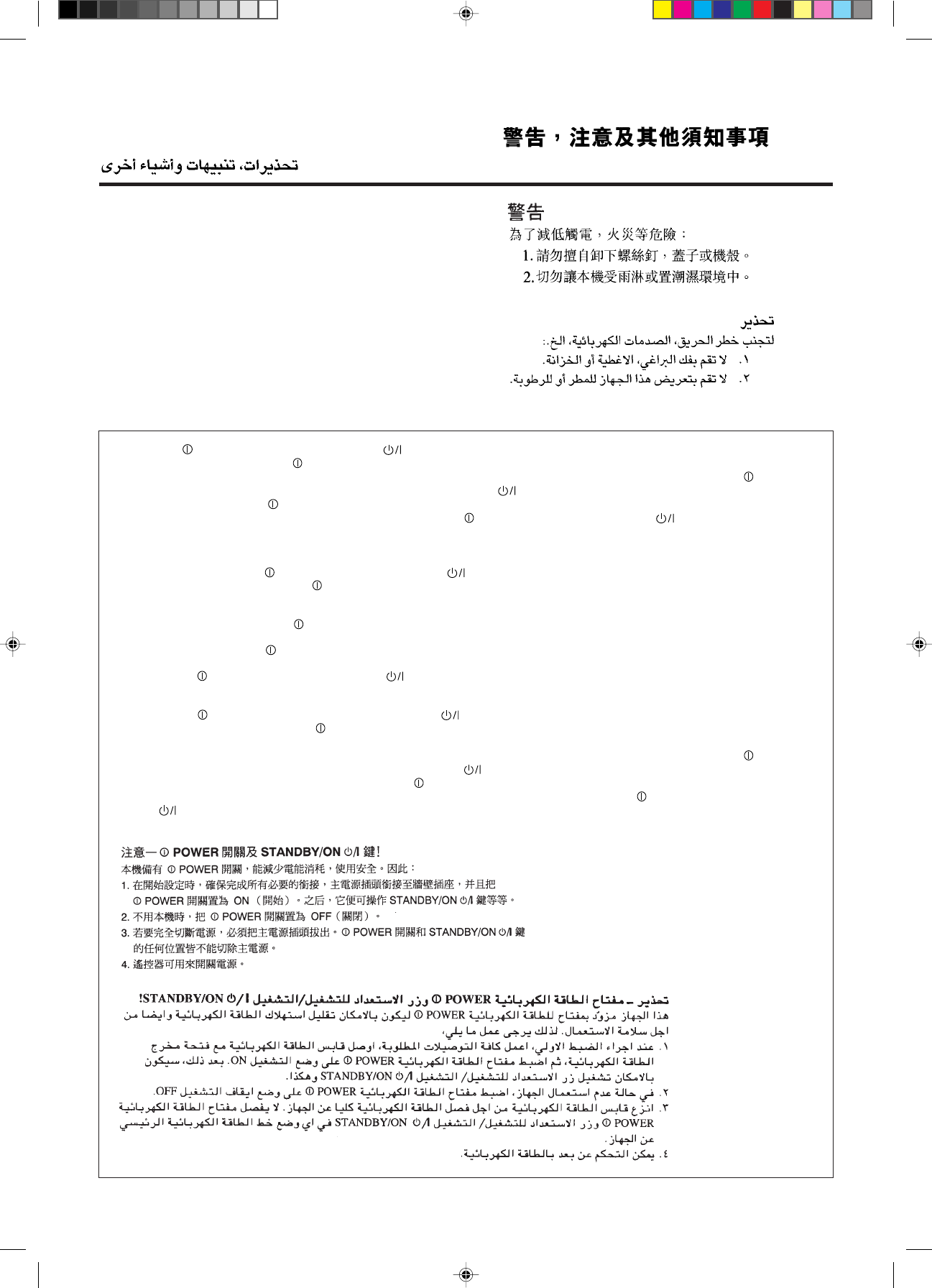
Caution: Proper Ventilation
To avoide risk of electric shock and fire and to protect from damage.
Locate the apparatus as follows:
Front: No obstructions open spacing.
Sides: No obstructions in 10 cm from the sides.
Top: No obstructions in 10 cm from the top.
Back: No obstructions in 15 cm from the back
Bottom: No obstructions, place on the level surface.
In addition, maintain the best possible air circulation as illustrated.
Precaución: Ventilación Adecuada
Para evitar el riesgo de choque eléctrico e incendio y para proteger el
aparato contra daños.
Ubique el aparato de la siguiente manera:
Frente: Espacio abierto sin obstrucciones
Lados: 10 cm sin obstrucciones a los lados
Parte superior: 10 cm sin obstrucciones en la parte superior
Parte trasera: 15 cm sin obstrucciones en la parte trasera
Fondo: Sin obstrucciones, colóquelo sobre una superficie
nivelada
Además, mantenga la mejor circulación de aire posible como se
ilustra.
Wall or obstructions
Pared u obstrucciones
Parede ou obstáculo Stand height 15 cm or more
Allura del soporte 15 cm o más
Base com altura de 15 cm ou mais
Front
Frente
Frente
RX-884PBK
Floor
Piso
Piso
Precaução: ventilação apropriada
Para prevenir o risco de choque elétrico ou incêndio e para proteger o
aparelho contra danos.
Localize-o da seguinte maneira:
Frente: Espaço aberto, sem obstruções
Lados: Espaço de 10 cm sem obstruções nos lados
Topo: Espaço de 10 cm sem obstruções acima
Atrás: Espaço de 15 cm sem obstruções atrás
Parte inferior: Sem obstruções. Coloque o aparelho em superfície
nivelada.
Mantenha, além disso, a maior circulação de ar possível, como indica
a ilustração.
Spacing 15 cm or more
Espacio de 15 cm o más
Espaço de 15 cm ou mais
EnglishEspañolPortuguês
RX-884P[U]SAFETY 98.2.20, 3:16 PM3

1
English
Table of Contents
Parts Identification...................................................................................... 3
Getting Started........................................................................................... 4
Before Installation................................................................................................................................................................... 4
Checking the Supplied Accessories ........................................................................................................................................ 4
Setting the Voltage Selector Switch ........................................................................................................................................ 4
Connecting the FM and AM Antennas ................................................................................................................................... 5
Connecting the Speakers......................................................................................................................................................... 6
Connecting Audio/Video Components ................................................................................................................................... 9
Connecting the Power Cord .................................................................................................................................................. 13
Putting Batteries in the Remote Control ............................................................................................................................... 13
Basic Operations ....................................................................................... 14
Turning the Power On and Off (Standby) ............................................................................................................................. 14
Selecting the Source to Play ................................................................................................................................................. 14
Adjusting the Volume............................................................................................................................................................ 15
Selecting the Front Speakers................................................................................................................................................. 16
Muting the Sound.................................................................................................................................................................. 16
Recording a Source ............................................................................................................................................................... 16
Attenuating the Input Signal ................................................................................................................................................. 17
Adjusting the Subwoofer Output Level ................................................................................................................................ 17
Basic Settings........................................................................................... 18
Changing the Source Name .................................................................................................................................................. 18
Selecting the Input Mode ...................................................................................................................................................... 18
Adjusting the Front Speaker Output Balance ....................................................................................................................... 19
Setting the Subwoofer Information....................................................................................................................................... 19
Listening at Low Volume (Loudness) ................................................................................................................................... 19
Digital Input (DIGITAL IN) Terminal Setting...................................................................................................................... 20
Setting the Speakers for the DSP Modes .............................................................................................................................. 20
One Touch Operation.................................................................................. 23
About the One Touch Operation ........................................................................................................................................... 23
Using the One Touch Operation............................................................................................................................................ 23
Receiving Radio Broadcasts ........................................................................ 24
Setting the AM Tuner Interval Spacing ................................................................................................................................ 24
Tuning in Stations Manually ................................................................................................................................................. 24
Using Preset Tuning .............................................................................................................................................................. 25
Selecting the FM Reception Mode ....................................................................................................................................... 26
Assigning Names to Preset Stations ..................................................................................................................................... 27
Using the SEA Modes ................................................................................ 28
Selecting Your Favorite SEA Mode ...................................................................................................................................... 28
Creating Your Own SEA Mode............................................................................................................................................. 29
EN01-13.RX-884P[U]/1.PM5 98.2.20, 1:54 PM1

2
English
Using the DSP Modes ................................................................................ 30
Using the 3D-PHONIC Modes ............................................................................................................................................. 31
Using the DAP Modes .......................................................................................................................................................... 34
Using the Dolby Digital and Dolby Pro Logic Modes ......................................................................................................... 36
Using the Theater Surround Mode........................................................................................................................................ 39
Using the On-Screen Menus........................................................................ 43
Selecting the Source to Play............................................................................................................................................ 43
Selecting the Different Sources for Picture and Sound ................................................................................................... 43
Using the DSP Modes ..................................................................................................................................................... 43
Adjusting the Front Speaker Output Balance.................................................................................................................. 44
Listening at Low Volume (Loudness) ............................................................................................................................. 44
Attenuating the Input Signal ........................................................................................................................................... 44
Adjusting the Subwoofer Output Level........................................................................................................................... 45
Adjusting the DSP Modes ............................................................................................................................................... 45
Selecting Your Favorite SEA Mode ................................................................................................................................ 46
Creating Your Own SEA Mode ....................................................................................................................................... 47
Basic Settings .................................................................................................................................................................. 47
Operating the Tuner......................................................................................................................................................... 48
Storing the Preset Stations .............................................................................................................................................. 48
Assigning Names to the Preset Stations .......................................................................................................................... 49
COMPU LINK Remote Control System......................................................... 50
TEXT COMPU LINK Remote Control System................................................. 51
Showing the Disc Information on the TV Screen ........................................................................................................... 52
Searching a Disc (Only for the CD Player)..................................................................................................................... 53
Using the User File (Only for the CD Player with the User File Function).................................................................... 55
Entering the Disc Information......................................................................................................................................... 56
Operating JVC’s Audio/Video Components ................................................... 58
Operating Other Manufactures’ Components ............................................... 62
Troubleshooting......................................................................................... 66
Specifications............................................................................................ 67
EN01-13.RX-884P[U]/1.PM5 98.3.6, 5:11 PM2
3
English
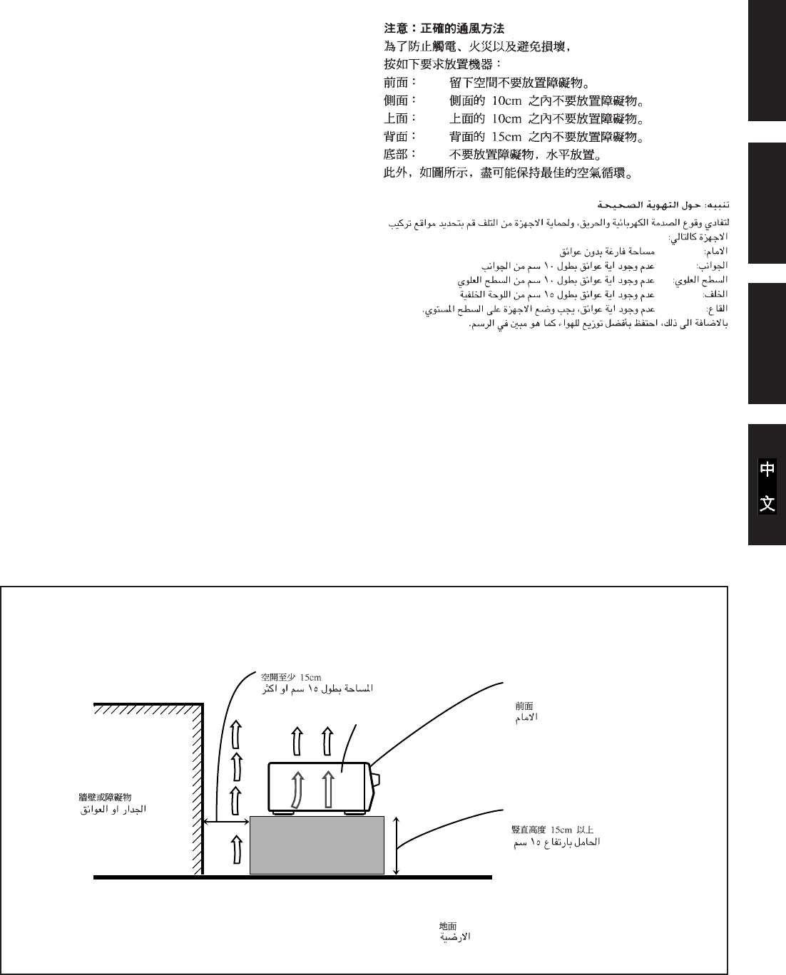
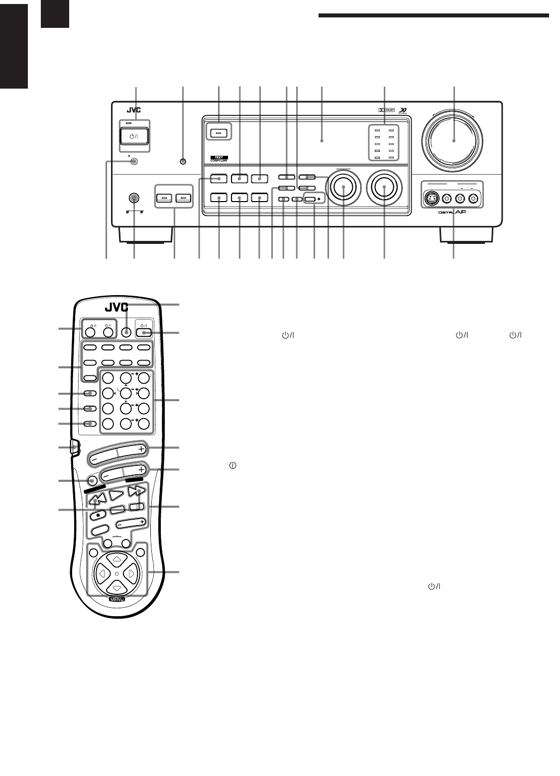
Parts Identification
Become familiar with the buttons and controls on the receiver before use.
™
£
§
ª
º
–
≠
Ÿ
¢
∞
¶
⁄
Refer to the pages in parentheses for details.
Front Panel
1
STANDBY/ON button and STANDBY
lamp (14)
2
Remote sensor (13)
3
DOLBY SURROUND button and lamp (38)
4
SEA MODE button (28) *
5
DIGITAL INPUT button (18)
6
FM/AM TUNING button (24) *
7
FM MODE button (26)
8
Display (14)
9
Source lamps (14)
0
MASTER VOLUME control (15)
-
POWER switch (13)
=
PHONES jack (16)
~
SPEAKERS 1/2 buttons and lamps (16)
!
DSP MODE button (31) *
@
BALANCE/SURROUND ADJUST button
(19, 32) *
#
SEA ADJUST button (29) *
$
SETTING button (19) *
%
TUNER/SEA MEMORY button (25, 27, 29)
^
SOUND SELECT/INPUT ATT. button
(15, 17)
&
LOUDNESS/SOURCE NAME button
(18, 19)
*
ONE TOUCH OPERATION button and
lamp (23)
(
TUNER PRESET button (25) *
)
MULTI JOG control
What this control actually does
depends on which function you are
trying to adjust. Before using this
control, select the function by
pressing one of the buttons marked
with *.
_
SOURCE SELECTOR control (14)
+
VIDEO input jacks (11)
Remote Control
¡
TV/CATV/DBS and VCR1
buttons (60, 61)
™
Source selecting buttons (15)
£
SURROUND MODE button (33)
¢
SOUND CONTROL button (28, 33, 58)
∞
CD DISC button (59)
§
Remote control mode selector (AUDIO/
TV/VCR, CATV/DBS) (14, 58, 62)
To operate an audio system, TV,
and VCR, set this selector to
“AUDIO/TV/VCR.”
To operate a CATV converter
and DBS tuner, set this selector to
“CATV/DBS.”
¶
MUTE button (16)
•
TUNING UP/TUNING DOWN buttons
(24)
Before using this control, make
sure that you have pressed FM/AM
button on the remote control.
ª
ANALOG/DIGITAL button (18)
º
AUDIO button (14)
–
10 keys for selecting preset channel (25)
10 keys for adjusting sound (28, 33)
10 keys for operating audio/video
components (58, 62)
≠
VOLUME buttons (+/–) (15)
Ÿ
CHANNEL buttons (+/–) (60, 62)
⁄
Operating buttons for audio/video
components (58, 62)
¤
MENU operating buttons (SET, EXIT, %,
fi, @, #) (43)
RM-SR884XU REMOTE CONTROL
/DBS
SOUND
CONTROL
CD
DISC
VCR1
ANALOG
/DIGITAL
AUDIO
DVD VCR1 VIDEOVCR2
CD
TV/DBS
TEST
REAR R
REAR L
SEA MODE
SUBWOOFER
TAPE/MD FM/AMPHONO
546
213
87
/P
9
0
+10
10
AUDIO/TV
/VCR
VCR1 TAPE
CONTROL
VOLUME
CHANNEL
MUTE
FF / ¢
PLAY
STOP
REC
TV/VIDEO
TV VOLUME
PAUSE
4 / REW
TV/CATV
CNTR
CNTR TONE
ENTER
MENU
EFFECT
CATV
/DBS
FM MODE/MUTE
100+
RETURN
SURROUND
MODE
O
N
S
C
R
E
E
N
C
O
N
T
R
O
L
SET EXIT
TUNING DOWN
TUNING UP
•
¤
–+
RX-884P AUDIO/VIDEO CONTROL RECEIVER
VIDEO
SPEAKERS
12
PHONES
DOLBY SURROUND
DSP MODE
BALANCE/SURROUND
ADJUST
SEA MODE
SEA ADJUST SETTING
MULTI JOG
MASTER VOLUME
SOURCE SELECTOR
S-VIDEO VIDEO AUDIOLR
DIGITAL INPUT
FM/AM TUNNING TUNER PRESET
TUNER/SEA MEMORY FM MODE
DVD
TV SOUND/DBS PHONO
TAPE/MDVCR 1
VCR 2 FM
AM
VIDEO
CD
SOUND SELECT
INPUT ATT.
LOUDNESS ONE TOUCH OPERATION
SOURCE NAME
COMPULINK
Remote
DIGITAL
STANDBY/ON
POWER
_ ON — OFF
STANDBY
ENHANCED COMPULINK CONTROL SYSTEM
-=~!@ )(*
&^%$
#_+
1 2 345 67 8 9 0
¡
EN01-13.RX-884P[U]/1.PM5 98.3.11, 5:29 PM3

4
English
Getting Started
This section explains how to connect audio/video components and speakers to the receiver, and how to
connect the power supply.
Before Installation
General
• Be sure your hands are dry.
• Turn the power off to all components.
• Read the manuals supplied with the components you are going to connect.
Locations
• Install the receiver in a location that is level and protected from moisture.
• The temperature around the receiver must be between –5˚ and 35˚ C (23˚ and 95˚ F).
• Make sure there is good ventilation around the receiver. Poor ventilation could cause
overheating and damage the receiver.
Handling the receiver
• Do not insert any metal object into the receiver.
• Do not disassemble the receiver or remove screws, covers, or cabinet.
• Do not expose the receiver to rain or moisture.
Checking the Supplied Accessories
Check to be sure you have all of the following items, which are supplied with the
receiver.
The number in the parentheses indicates quantity of the pieces supplied.
• Remote Control (1)
• Batteries (2)
• AM Loop Antenna (1)
• FM Antenna (1)
• Audio Signal Attenuating Cord (1)
• AC Plug Adaptor (1) (except for People’s Republic of China)
If anything is missing, contact your dealer immediately.
Setting the Voltage Selector Switch
Before connections, always do the following first if necessary.
How to set the voltage selector:
Set the correct voltage for your area with the voltage
selector switch on the rear panel. Use a screw driver to
rotate the switch so the number the arrow is pointing at is
the same as the voltage where you are plugging in the
receiver.
127V
220V
230 – 240V
110V
LINE VOLTS
EN01-13.RX-884P[U]/1.PM5 98.2.20, 1:54 PM4

5
English
AM
EXT
AM
LOOP
GND
FM
75
FM GND
ANTENNA
23
1
4
34
21
Connecting the FM and AM Antennas
FM Antenna Connections
Notes:
• Make sure the antenna
conductors do not touch any
other terminals, connecting
cords and power cord. This
could cause poor reception.
• If reception is poor, connect
an outdoor single vinyl-
covered wire to the AM EXT
terminal. (Keep the AM loop
antenna connected.)
Note:
If reception is poor, connect the
outside antenna.
Before attaching a 75
Ω
coaxial
cable (the kind with a round wire
going to an outside antenna),
disconnect the supplied FM wire
antenna.
AM Antenna Connections
AM Loop Antenna
Turn the loop until you
have the best reception.
Snap the tabs on the loop
into the slots of the base to
assemble the AM loop.
How to strip the 75Ω coaxial cable and connect it to the FM
terminals
1. Strip back the outside covering of the 75Ω coaxial cable to expose the braided
metallic mesh about 20 mm (13/16 inches).
2. Pull the mesh back and twist it into a single connector as shown in the illustration
above.
3. Strip the insulation about 10 mm (7/16 inches) back from the central wire.
4. Insert the twisted mesh and the central wire to the FM terminals, as shown in the
illustration above.
Outdoor single vinyl-
covered wire
AM
EXT
AM
LOOP
GND
FM
75
FM GND
ANTENNA
23
1
Getting Started
Outside FM Antenna Wire
Extend the FM wire antenna horizontally.
FM Antenna
20 mm
(13/16 in.)
10 mm
(7/16 in.)
EN01-13.RX-884P[U]/1.PM5 98.2.20, 1:54 PM5
6
English
Connecting the Speakers
You can connect the following speakers:
• Two pairs of front speakers to produce normal stereo sound.
• One pair of rear speakers to enjoy the surround effect.
• One center speaker to produce more effective surround effect (to emphasize human
voices).
• One subwoofer to enhance the bass.
IMPORTANT:
After connecting the speakers listed above, set the speaker setting information
properly to obtain the best possible performance. For details, see pages 19 and 20.
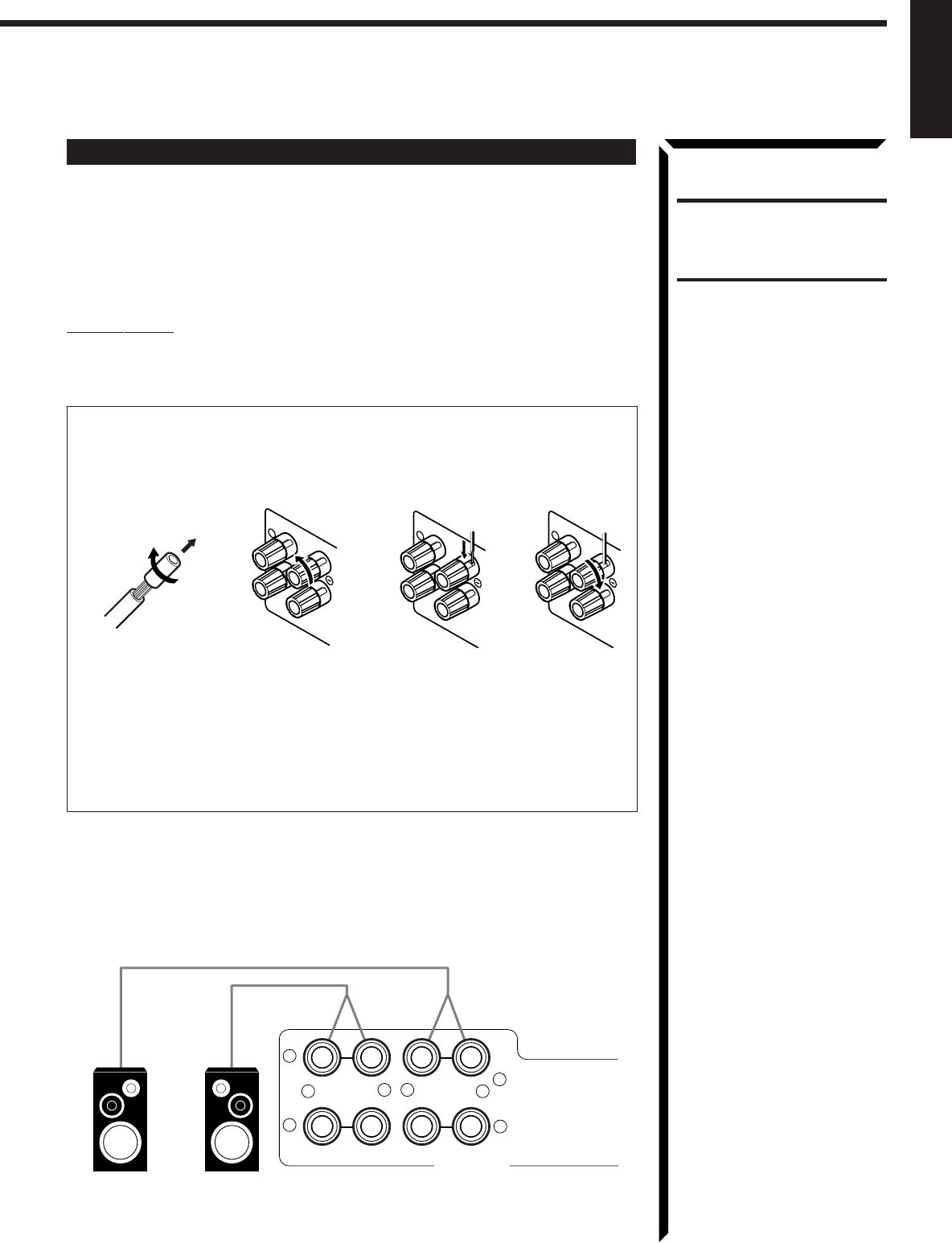
For each speaker (except for subwoofer), connect the (–) and (+) terminals on the
rear panel to the (–) and (+) terminals marked on the speakers. For connecting a
subwoofer, see page 7.
1 Cut, twist and remove the insulation at the end of each speaker signal cable.
2 Turn the knob counterclockwise.
3 Insert the speaker signal cable.
4 Turn the knob clockwise.
Connecting the front speakers
Connect the front speakers to the FRONT SPEAKERS terminals.
You can connect two pairs of front speakers (one pair to the FRONT SPEAKERS 1
terminals, and another pair to the FRONT SPEAKERS 2 terminals).
RIGHT
1
RIGHT
1
134
RIGHT
1
2
CAUTION:
Use speakers with the
SPEAKER IMPEDANCE
indicated by the speaker
terminals.
Right Speaker
FRONT SPEAKERS
+–
+–
RIGHT LEFT
1
2
1
2
Left Speaker
EN01-13.RX-884P[U]/1.PM5 98.2.20, 1:54 PM6
7
English
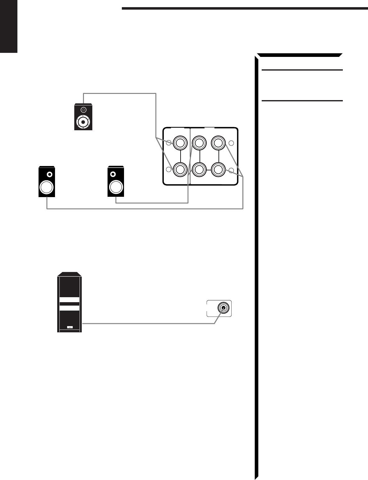
Connecting the rear and center speakers
Connect the rear speakers to the REAR SPEAKERS terminals and a center speaker to
the CENTER SPEAKER terminals.
Connecting the subwoofer speaker
Connect the input jack of a powered subwoofer to the SUBWOOFER OUT jack on the
rear panel, using a cable with RCA pin plugs.
Center speaker
Left rear speaker Right rear speaker
Getting Started
CAUTION:
Use speakers with the
SPEAKER IMPEDANCE
indicated by the speaker
terminals.
Powered subwoofer
SUBWOOFER
OUT
+
–
+
–
RIGHT LEFT
REAR
SPEAKERS
CENTER
SPEAKER
EN01-13.RX-884P[U]/1.PM5 98.3.10, 1:12 PM7
8
English
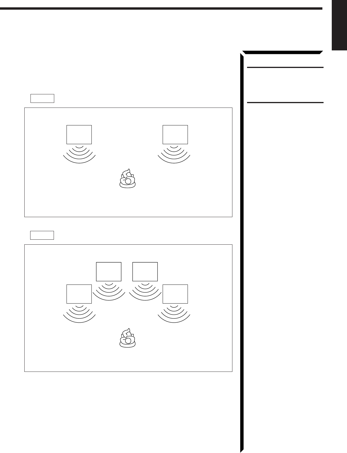
About the speaker impedance
The required speaker impedance of the front speakers does differ depending on whether
both the FRONT SPEAKERS 1 and FRONT SPEAKERS 2 terminals are used or
only one of them is used.
CAUTION:
When connecting speakers, use
speakers with the same
SPEAKER IMPEDANCE
indicated by the speaker
terminals.
CASE 1 When you connect only one set of front speakers
CASE 2 When you connect two sets of front speakers
Use front speakers with 4 — 16 ohm impedance.
Front
Speaker
1
Front
Speaker
1
Front
Speaker
1
Front
Speaker
1
Front
Speaker
2
Front
Speaker
2
Use front speakers with 8 — 16 ohm impedance.
EN01-13.RX-884P[U]/1.PM5 98.2.20, 1:54 PM8
9
English
Connecting Audio/Video Components
You can connect the following audio/video components to this receiver. Refer also to the
manuals supplied with your components. If you want to connect a component not listed
in the table below, refer to the manual supplied with it.
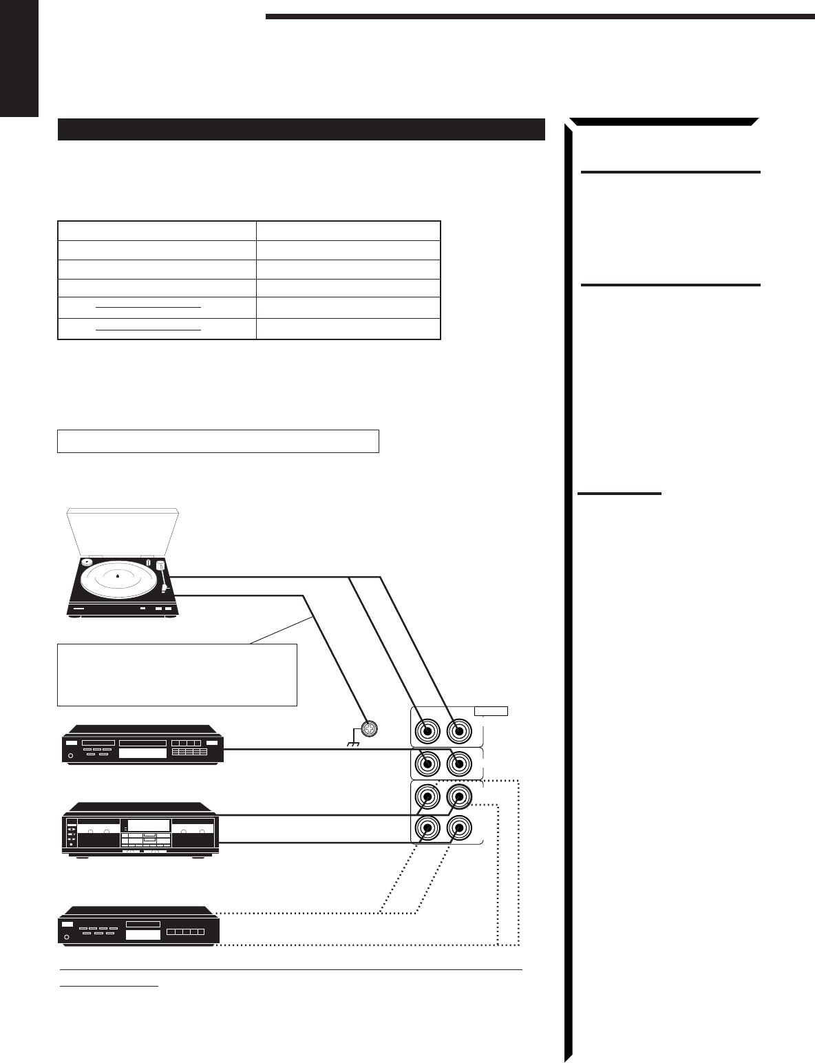
Analog connections
Audio component connections
Use the cables with RCA pin plugs (not supplied).
Connect the white plug to the audio left jack, and the red plug to the audio right jack.
CAUTION:
If you connect a sound-
enhancing device such as a
graphic equalizer between the
source components and this
receiver, the sound output
through this receiver may be
distorted.
Notes:
• Any turntables incorporating
a small-output cartridge such
as an MC (moving-coil type)
must be connected to this
receiver through a
commercial head amplifier or
step-up transformer. Direct
connection may result in
insufficient volume.
• You can connect either a
cassette deck or an MD
recorder to the TAPE/MD
jacks. When connecting an
MD recorder to the TAPE/MD
jacks, change the source
name, which will be shown on
the display when selected as
the source, to “MD.” See page
18 for details.
• When connecting an audio/
video component (ex.: Video
CD player) with “karaoke” —
singing along — function, use
the audio signal attenuating
cord supplied with this
receiver. If not, sound may be
distorted.
Audio Components Video Components
• Turntable • DVD player*
• CD player* • TV
• Cassette deck or MD recorder* • DBS tuner*
• VCRs
• Video camera
* You can connect these components using the methods described in “Analog
connections” (below) or in “Digital connections” (see page 12).
GND
RIGHT LEFT
TAPE
/MD
IN
(PLAY)
OUT
(REC)
CD
PHONO
AUDIO
If your audio components have a COMPU LINK-3 or TEXT COMPU
LINK terminal
• See also page 50 for detailed information about the connection and the COMPU
LINK-3 remote control system.
• See also page 51 for detailed information about the connection and the TEXT
COMPU LINK remote control system.
Cassette deck
or
MD recorder
To audio output
To audio output
To audio input
To audio input
To audio output
If an earth cable is provided for your
turntable, connect the cable to the
screw marked GND on the rear panel.
To audio output
Turntable
CD player
Getting Started
EN01-13.RX-884P[U]/1.PM5 98.2.20, 1:54 PM9
10
English
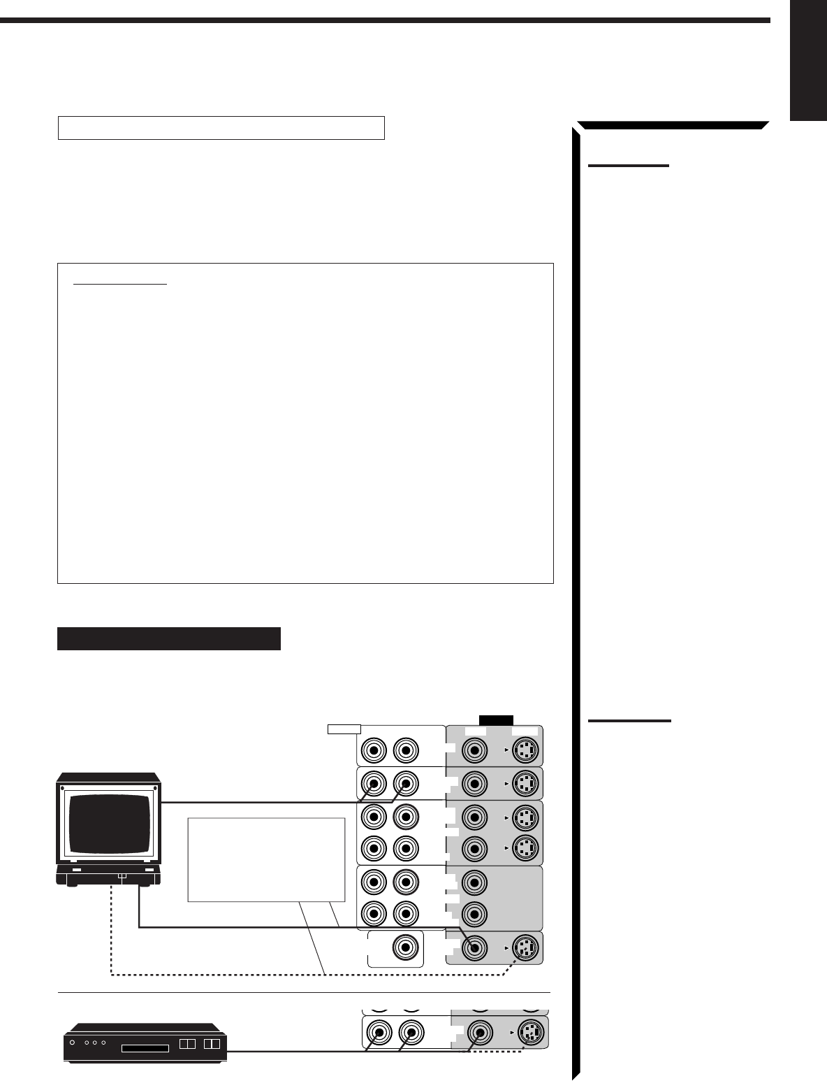
Video component connections
Use the cables with RCA pin plugs (not supplied).
Connect the white plug to the audio left jack, the red plug to the audio right jack, and
the yellow plug to the video jack.
If your video components have S-video (Y/C-separation) terminals, connect them using
S-video cables (not supplied). Connecting these video components through the S-video
input/output terminals will give you better picture playback (or recording) quality.
IMPORTANT:
This receiver is equipped with both the composite video and S-video input/output
terminals for connecting video components.
You do not have to connect both the composite video and S-video terminals.
However, remember that the video signals from the composite video input
terminals are output only through the composite video output terminals,
while the ones from the S-video input terminals are output only through the
S-video output terminals.
Therefore, if a recording video component and a playing video component are
connected to the receiver through the different video terminals, you cannot record
the picture from the playing component on the recording component. In addition,
if the TV and a playing video component are connected to the receiver through the
different video terminals, you cannot view the playback picture from the playing
component on the TV.
To view and record the playback picture from the video component connected
to the VCR 2 jacks, you must connect the TV and the recording video
component through the composite video terminals.
Connecting the TV and/or DBS tuner
You can connect either the TV or DBS tuner to the TV SOUND/DBS jacks.
To audio output
To composite video input
To S-video input
Connect the TV to the
MONITOR OUT jack to
view the playback picture
from the other connected
video components.
TV SOUND
/DBS
DBS
DBS tuner
To audio/video output
RIGHT
VIDEO
VIDEO S-VIDEORIGHT LEFT
AUDIO
SUBWOOFER
OUT MONITOR
OUT
VCR 1
IN
(PLAY)
OUT
(REC)
IN
(PLAY)
OUT
(REC)
TV SOUND
/DBS
DVD
VCR 2
TV
Notes:
• Use the video components of
the PAL color system.
• When connecting the TV to
the TV SOUND/DBS jacks,
DO NOT connect the TV’s
video output to these video
input terminals.
• When connecting the DBS
tuner to the TV SOUND/DBS
jacks, change the source
name, which will be shown on
the display when selected as
the source, to “DBS.” See
page 18 for details.
• To enjoy Dolby Digital with the
DBS tuner as the source,
connect the DBS tuner using
the method described in
“Digital connections” on page
12.
Note:
When connecting an audio/
video component (ex.: Video
CD player) with “karaoke” —
singing along — function, use
the audio signal attenuating
cord supplied with this
receiver. If not, sound may be
distorted.
EN01-13.RX-884P[U]/1.PM5 98.3.3, 2:45 PM10
11
English
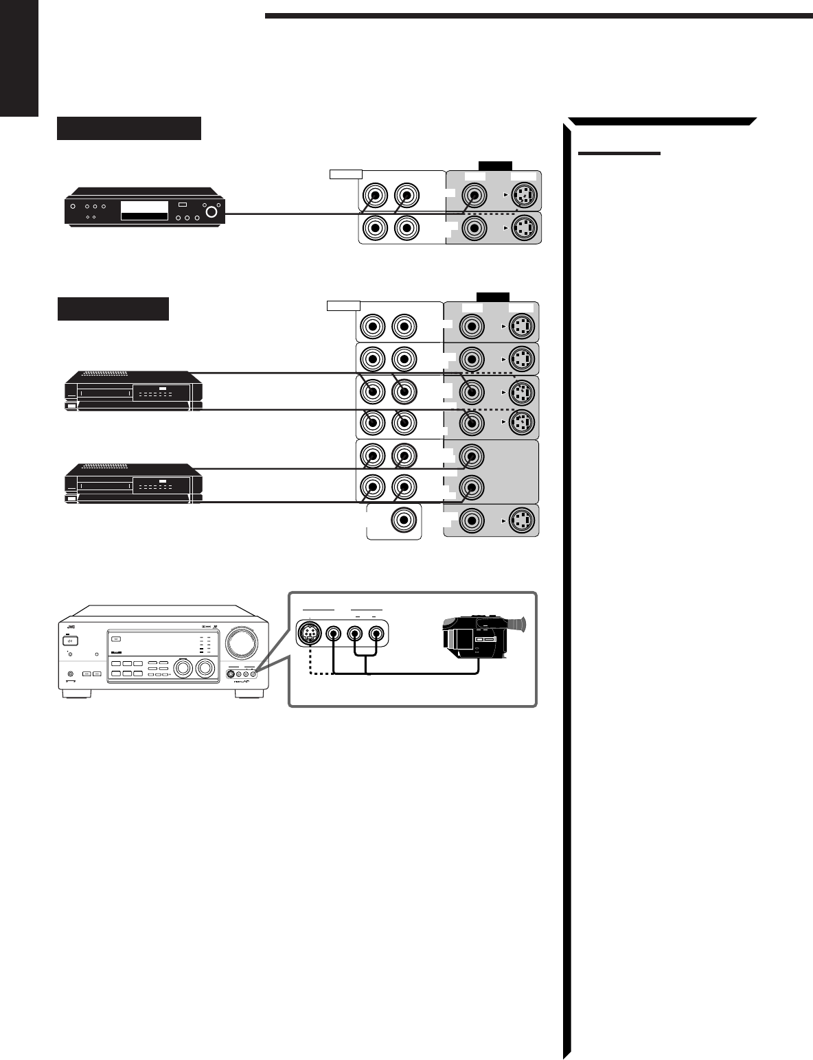
Connecting DVD player
RIGHT
VIDEO
VIDEO S-VIDEORIGHT LEFT
AUDIO
TV SOUND
/DBS
DVD
DVD To audio/video
output
DVD player
Connecting VCRs
RIGHT
VIDEO
VIDEO S-VIDEORIGHT LEFT
AUDIO
SUBWOOFER
OUT MONITOR
OUT
VCR 1
IN
(PLAY)
OUT
(REC)
IN
(PLAY)
OUT
(REC)
TV SOUND
/DBS
DVD
VCR 2
S-VHS
VHS
S-VHS (or VHS) VCR
To audio/video output
To audio/video input
To audio/video output
To audio/video input
Note:
To enjoy Dolby Digital with the
DVD player as the source,
connect the DVD player, using
the method described in “Digital
connections” on page 12.
VHS VCR
VIDEO
S-VIDEO VIDEO AUDIOLR
–+
RX-884P AUDIO/VIDEO CONTROL RECEIVER
VIDEO
SPEAKERS
12
PHONES
DOLBY SURROUND
DSP MODE
BALANCE/SURROUND
ADJUST
SEA MODE
SEA ADJUST SETTING
MULTI JOG
MASTER VOLUME
SOURCE SELECTOR
S-VIDEO VIDEO AUDIOLR
DIGITAL INPUT FM/AM TUNNING TUNER PRESET
TUNER/SEA MEMORY FM MODE
DVD
TV SOUND/DBS PHONO
TAPE/MDVCR 1
VCR 2 FM
AM
VIDEO
CD
SOUND SELECT
INPUT ATT.
LOUDNESS ONE TOUCH OPERATION
SOURCE NAME
COMPULINK
Remote
DIGITAL
STANDBY/ON
POWER
_ ON — OFF
STANDBY
ENHANCED COMPULINK CONTROL SYSTEM
To audio/video output
Video camera
Getting Started
EN01-13.RX-884P[U]/1.PM5 98.2.20, 1:55 PM11
12
English
DVD
DIGITAL IN
DIGITAL 3 (CD)
DIGITAL 2 (DVD)
DIGITAL 1 (DBS)
PCM/DOLBY DIGITAL
DBS
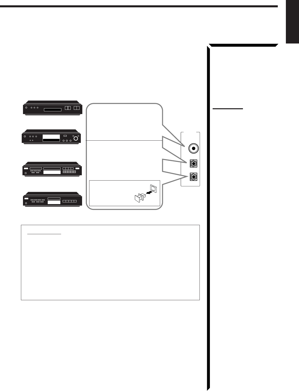
Digital connections
This receiver is equipped with three DIGITAL IN terminals — one digital coaxial
terminal and two digital optical terminals.
To enjoy Dolby Digital, you have to connect the source components using the DIGITAL
IN terminals.
You can connect any component to any one of the digital terminals using the digital
coaxial cable (not supplied) or digital optical cable (not supplied).
DVD player
CD player
MD recorder
DBS tuner
When the component has a digital
optical output terminal, connect it
to the DIGITAL2 (DVD) or
DIGITAL3 (CD) terminal, using the
digital optical cable (not supplied).
When the component has a digital
coaxial output terminal, connect it
to the DIGITAL1 (DBS) terminal,
using the digital coaxial cable (not
supplied).
Before connecting a
digital optical cable,
unplug the protective
plug.
IMPORTANT:
• When connecting the DVD player or the DBS tuner using the digital terminal,
you also need to connect it to the video jack (either composite video terminal
or S-video terminal) on the rear. Without connecting it to the video jack, you
can view no playback picture.
• After connecting the above components using the DIGITAL IN terminals, set
the following correctly if necessary.
– Select the digital input mode correctly. For details, see “Selecting the Input
Mode” on page 18.
– Set the digital input (DIGITAL IN) terminal setting correctly. For details,
see “Digital Input (DIGITAL IN) Terminal Setting” on page 20.
Notes:
• When shipped from the
factory, the DIGITAL IN
terminals has been set for use
with the following
components.
– DIGITAL 1 (coaxial): For
DBS tuner
– DIGITAL 2 (optical): For
DVD player
– DIGITAL 3 (optical): For CD
player
• When you want to operate the
CD player or MD recorder
using the COMPU LINK
remote control system,
connect the target component
also as described in “Analog
connections” (see page 9).
EN01-13.RX-884P[U]/1.PM5 98.2.20, 1:55 PM12
13
English
Connecting the Power Cord
Before plugging the receiver into an AC outlet, make sure that all connections have been
made.
1. Plug the power cord into an AC outlet.
2. Press POWER to set it in the _ON position.
The STANDBY lamp lights up. A small amount of power
is always consumed.
To shut off the power completely
Press POWER to set it in the —OFF position.
Keep the power cord away from the connecting cables and the antenna. The power cord
may cause noise or screen interference. We recommend that you use a coaxial cable to
connect the antenna, since it is well-shielded against interference.
The difference between the POWER switch and the
STANDBY/ON button
• The POWER switch is the mains supply switch, allowing the receiver to
connect to the mains supply. To shut off the power completely, press the
POWER switch to set it in the —OFF position.
• The STANDBY/ON button is a functional on/off (standby) switch, and
does not disconnect the receiver from the mains supply. A small amount of
power is consumed even in standby mode for the receiver to accept signals from
the remote control.
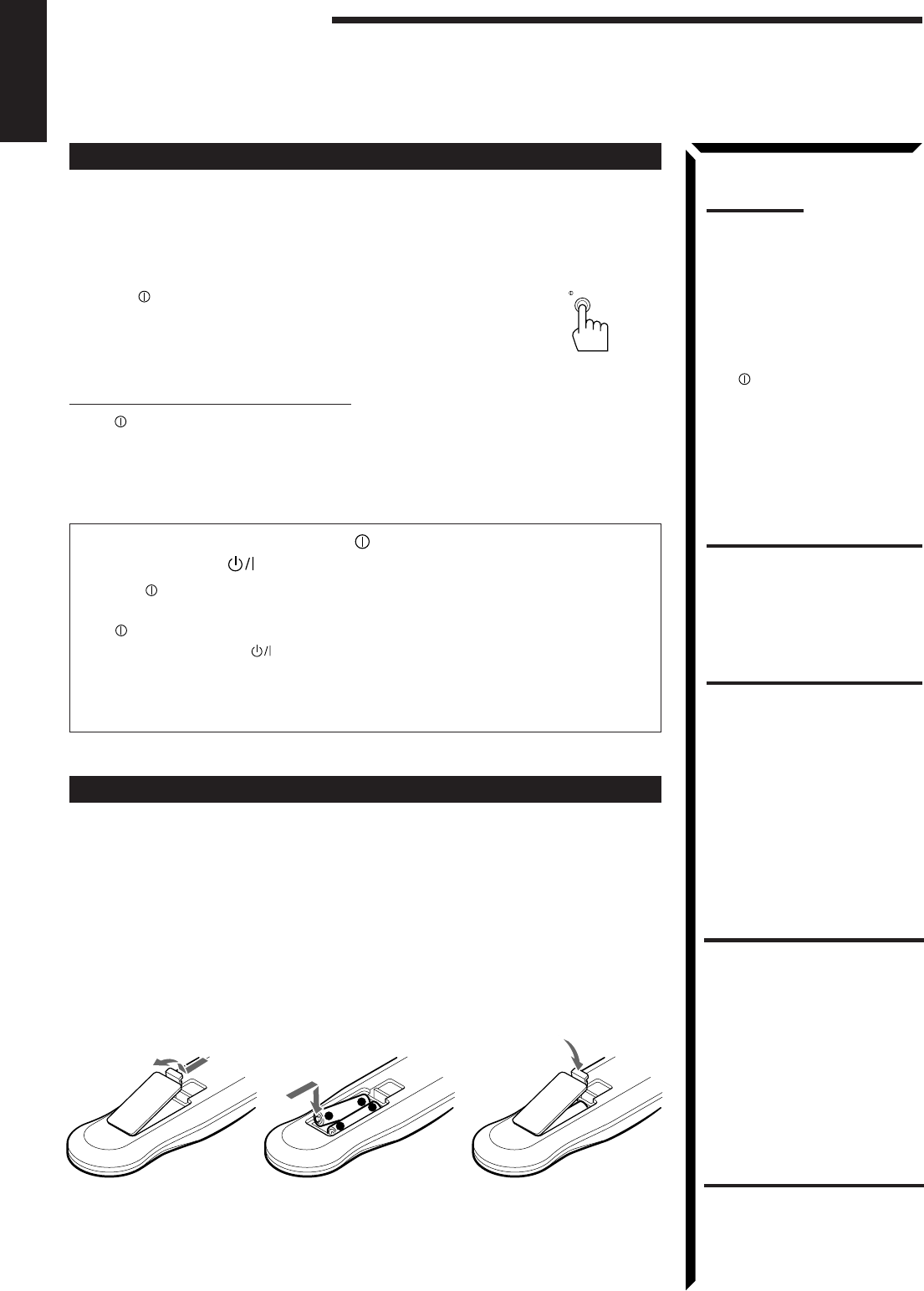
Putting Batteries in the Remote Control
Before using the remote control, put two supplied batteries first. When using the remote
control, aim the remote control directly at the remote sensor on the receiver.
1. On the back of the remote control, remove the battery cover as illustrated.
2. Insert batteries. Make sure to observe the proper polarity: (+) to (+) and (–) to
(–).
3. Replace the cover.
If the range or effectiveness of the remote control decreases, replace the batteries. Use
two R03 (UM-4)/AAA (24F) type dry-cell batteries.
Notes:
• If the wall outlet does not
match the AC plug, use the
supplied AC plug adaptor.
• The preset settings such as
preset channel and sound
adjustment may be erased in
the following cases:
– When you press
POWER to set it in the
—
OFF position.
– When you unplug the
power cord.
– When a power failure
occurs.
CAUTIONS:
• Do not touch the power cord
with wet hands.
• Do not pull on the power cord
to unplug the cord. When
unplugging the cord, always
grasp the plug so as not to
damage the cord.
R03 (UM-4)/AAA (24F)
+
-
-
+
CAUTION:
Follow these precautions to
avoid leaking or cracking cells:
• Place batteries in the remote
control so they match the
polarity indicated: (+) to (+)
and (–) to (–).
• Use the correct type of
batteries. Batteries that look
similar may differ in voltage.
• Always replace both batteries
at the same time.
• Do not expose batteries to
heat or flame.
Getting Started
POWER
_ ON — OFF
EN01-13.RX-884P[U]/1.PM5 98.2.20, 1:55 PM13

14
English
Basic Operations
The following operations are commonly used when you play any sound source.
IMPORTANT:
When using the Remote Control, check to see if its remote control
mode selector is set to the correct position:
To operate an audio system, TV, and VCR, set it to “AUDIO/TV/
VCR.”
To operate a CATV converter and DBS tuner, set it to “CATV/
DBS.”
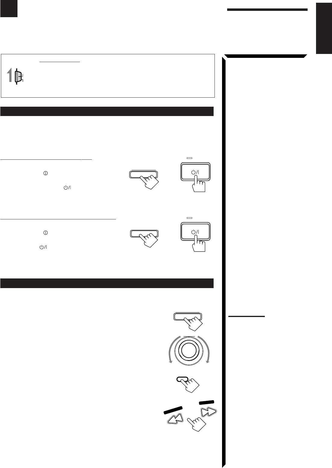
Turning the Power On and Off (Standby)
On the front panel:
To turn on the power, press STANDBY/ON .
The STANDBY lamp goes off. The name of the current source (or
station frequency) appears on the display.
To turn off the power (into standby mode),
press STANDBY/ON again.
The STANDBY lamp lights up.
From the remote control:
To turn on the power, press AUDIO .
The STANDBY lamp goes off. The name of the current source (or
station frequency) appears on the display.
To turn off the power (into standby mode), press AUDIO
again.
The STANDBY lamp lights up.
Selecting the Source to Play
On the front panel:
Turn SOURCE SELECTOR until the source name you want
appears on the display.
As you turn the selector, the source changes as follows:
The selected source lamp also lights up.
AUDIO/TV
/VCR
CATV
/DBS
SOURCE SELECTOR
Current source name appears
100 1k 10k
VOLUME
FR
Current volume level
is shown here
Source lamps on the
front panel
DVD
TV SOUND/DBS PHONO
TAPE/MDVCR 1
VCR 2 FM
AM
VIDEO
CD
STANDBY
STANDBY/ON
STANDBY
STANDBY/ON
FM
TV SOUND/DBS
VIDEO
PHONOCD TAPE/MD AM DVD
VCR1VCR2
Note:
When connecting an MD
recorder (to the TAPE/MD
jacks), and a DBS tuner (to the
TV SOUND/DBS jacks), change
the source name appears on
the display. For details, see
page 18.
What are the following
indicators?
When you select the source
encoded with Dolby Digital and
start playback, the following
indicators light up on the display
to show the signal being input to
this receiver. (Only the indicators
for the received signals light up.)
L: Left front channel
R: Right front channel
C: Center channel
LS: Left rear channel
RS: Right rear channel
S: Rear channel (monaural)
LFE: Subwoofer channel
S
C
DIGITAL
LS
L
LFE
RS
R
Note:
Pressing the STANDBY/ON
button again turns off the power
(into standby mode) and lights
the STANDBY lamp. A small
amount of power is consumed
in standby mode. To turn the
power off completely, press the
POWER switch to set it in the
—
OFF position on the front
panel.
AUDIO
CH–
CNTR
100 1k 10k
DIGITAL
MUTE AUTO VOLUME
THEATER DRAMA
LIVE CLUB ACTION
DANCE CLUB
HALL HEADPHONE
PAVILION
PRO LOGIC TUNED
STEREO
FR
LS
L
LEE
S
CD S P
3D-PHONC LOUDNESS
ATT
RS
R
S E A
Selected source name appears
EN14_23.RX-884P[U]/1.PM5 98.2.24, 9:03 PM14
15
English
Note:
When you press one of the
source selecting buttons
marked above with an asterisk
(*), the receiver automatically
turns on.
DVD VCR1 VIDEOVCR2
CD
TV/DBS
TAPE/MD FM/AMPHONO
From the remote control:
Press one of the source selecting buttons directly.
DVD Selects the DVD player.
VCR1 Selects the video component connected to the VCR1
jacks.
VCR2 Selects the video component connected to the VCR2
jacks.
VIDEO Selects the video component connected to the
VIDEO jacks.
CD* Selects the CD player.
TAPE/MD* Selects the cassette deck or the MD recorder.
PHONO* Selects the turntable.
FM/AM* Selects an FM and AM broadcast.
Each time you press the button, the band alternates
between FM and AM.
TV/DBS • Selects TV sounds when the remote control selector is set to “AUDIO/
TV/VCR.”
• Selects the DBS tuner when the remote control selector is set to
“CATV/DBS.”
Selecting different sources for picture and sound
You can watch picture from a video component while listening to sound from another
component.
On the front panel:
1. Press SOUND SELECT briefly while viewing the picture
from a video component such as the VCR or DVD player,
etc.
“SOUND SELECT” appears on the display.
2. Turn SOURCE SELECTOR to select the sound (except the
TV sound), while the indication of the above step is still on
the display.
From the remote control:
Press one of the audio source selecting buttons (CD, TAPE/MD, PHONO, FM/AM),
while viewing the picture from a video component such as the VCR or DVD player, etc.
Adjusting the Volume
On the front panel:
To increase the volume, turn MASTER VOLUME clockwise.
To decrease the volume, turn it counterclockwise.
When you turn MASTER VOLUME rapidly, the volume
level also changes rapidly.
When you turn MASTER VOLUME slowly, the volume
level also changes slowly.
From the remote control:
To increase the volume, press VOLUME +.
To decrease the volume, press VOLUME –.
Notes:
• Once you have selected a
video source, pictures of the
selected source is sent to the
TV until you select another
video source.
• When you select TV sound as
the source, this function does
not work.
Basic Operations
SOUND SELECT
INPUT ATT.
SOURCE SELECTOR
–+
MASTER VOLUME
–
+
VOLUME
CAUTION:
Always set the volume to the
minimum before starting any
source. If the volume is set at its
high level, the sudden blast of
sound energy can permanently
damage your hearing and/or
ruin your speakers.
Note:
The volume level can be
adjusted within the range of “0”
(minimum) to “90” (maximum).
EN14_23.RX-884P[U]/1.PM5 98.3.11, 10:16 AM15

16
English
Selecting the Front Speakers
On the front panel
only
:
When you have connected two pairs of the front speakers, you can
select which to use.
Press SPEAKERS 1 or SPEAKERS 2 to select the speaker to
use.
Each time you press the button, the lamp on the respective button turns on and off.
When the lamp on either button lights up, the respective speakers are activated.
IMPORTANT:
You can activate two pairs of the front speakers at the same time only when no
signals are sent to the center and rear speakers. Otherwise, activating one pair of
the speakers deactivates the other.
Listening only with headphones
1. Connect a pair of headphones to the PHONES jack on the front panel.
2. Press SPEAKERS 1 and/or 2 so that no lamps on the buttons are turned on.
Muting the Sound
From the remote control
only
:
Press MUTE to mute the sound through all speakers
and headphones connected.
“MUTE” appears on the display and the volume turns off (the
volume level indicator also goes off).
To restore the sound, press MUTE again so that “OFF” appears on the display.
Turning MASTER VOLUME or pressing VOLUME +/– also restores the sound at the
previous volume level.
Recording a Source
You can record any source playing through the receiver to the cassette deck or the MD
recorder connected to the TAPE/MD jacks and the VCRs connected to the VCR1 and
VCR2 jacks at the same time.
While recording, you can listen to the selected sound source at whatever sound level
you like, without affecting the sound levels of the recording.
MUTE
SPEAKERS
12
Note:
The output volume level and
SEA modes cannot affect the
recording.
Note:
If you use any of the DSP
modes other than the 3D-
PHONIC modes and
“HEADPHONE” with both front
speakers activated, the
speakers connected to the
FRONT SPEAKERS
2
terminals are deactivated.
IMPORTANT:
When recording the digital
source, turn off the DSP mode.
CAUTION:
Be sure to turn down the volume
before connecting or putting on
headphones, as high volume
can damage both the
headphones and your hearing.
Note:
You cannot shut off the sound
through the subwoofer using the
SPEAKERS 1 and 2 buttons.
EN14_23.RX-884P[U]/1.PM5 98.3.10, 9:04 PM16
17
English
Attenuating the Input Signal
When the input level of the playing source through the analog terminals is too high, the
sounds will be distorted. If this happens, you need to attenuate the input signal level to
prevent the sound distortion.
On the front panel
only
:
Press and hold SOUND SELECT/INPUT ATT. until “INPUT
ATT ON” appears on the display.
The ATT indicator also lights up on the display.
Each time you press and hold the button, the input attenuator mode
turns on (“INPUT ATT ON”) and off (“INPUT NORMAL”).
You can set input attenuator mode separately for each source.
Adjusting the Subwoofer Output Level
You can adjust the subwoofer output level if you have selected “YES” for the
“SUBWOOFER” (see page 19).
Once it has been adjusted, the receiver memorizes the adjustment.
On the front panel:
1. Press BALANCE/SURROUND ADJUST repeatedly until
“SUBWFR LEVEL” appears on the display.
The display changes to show the current setting.
2. Turn MULTI JOG to adjust the subwoofer output level (–
10 dB to +10 dB), while the indication of the previous step is
still on the display.
From the remote control:
1. Press SOUND CONTROL.
10 keys are activated for sound adjustments.
2. Press SUBWOOFER +/– to adjust the subwoofer output
level (–10 dB to +10 dB).
MULTI JOG
BALANCE/SURROUND
ADJUST
SOUND SELECT
INPUT ATT.
Notes:
• This function is available only
for the sources connected
using the analog terminals.
• This function takes effect only
when the DSP mode is in use.
Basic Operations
SOUND
CONTROL
SUBWOOFER
FM MODE/MUTE
100+
0
+10
EN14_23.RX-884P[U]/1.PM5 98.3.6, 5:15 PM17
18
English
Basic Settings
Some of the following settings are required after connecting and positioning your speakers in your listening
room, while others will make operations easier.
IMPORTANT:
When using the Remote Control, check to see if its remote control
mode selector is set to the correct position:
To operate this receiver, set it to “AUDIO/TV/VCR” (except when
selecting the DBS tuner as the source).
Changing the Source Name
When you have connected an MD recorder to the TAPE/MD jacks or the DBS tuner to
the TV SOUND/DBS jacks on the rear panel. Change the source name shown on the
display when you select the MD recorder or DBS tuner as the source.
On the front panel
only
:
1. When changing the source name from “TAPE” to “MD”:
• Turn SOURCE SELECTOR until “TAPE” appears.
When changing the source name from “TV SOUND” to
“DBS”:
• Turn SOURCE SELECTOR until “TV SOUND”
appears.
2. Press and hold LOUDNESS/SOURCE NAME until
“ASSGN. MD” or “ASSGN. DBS” appears on the
display.
To change the source names to “TAPE” or “TV SOUND,” repeat the same procedure
above (in step 1, select “MD” or “DBS” then press and hold SOURCE NAME).
Selecting the Input Mode
When you have connected some components such as CD player, MD recorder, DVD
player and the DBS tuner using digital terminals (see page 12), you need to change the
input mode for these components to the digital input.
On the front panel:
1. Turn SOURCE SELECTOR until the source (CD, MD,
DBS, or DVD) for which you want to change the input
mode from analog input to digital input.
2. Press DIGITAL INPUT to change the input mode.
Each time you press the button, the input mode alternates
between the digital input and analog input.
From the remote control:
1. Press the source selecting button (CD, TAPE/MD, TV/DBS,
or DVD) for which you want to change the input mode from
analog input to digital input.
2. Press ANALOG/DIGITAL to change the input mode.
Each time you press the button, the input mode alternates
between the digital input and analog input.
AUDIO/TV
/VCR
CATV
/DBS
Note:
Without changing the source
name, you can still use the
connected components.
However, there may be some
inconvenience.
– “TAPE” or “TV SOUND” will
appear on the display when
you select the MD recorder or
DBS tuner.
– You cannot use the digital
input (see below) for the MD
recorder and the DBS tuner.
– You cannot use the COMPU
LINK remote control system
(see page 50) to operate the
MD recorder.
SOURCE SELECTOR
LOUDNESS
SOURCE NAME
Note:
Once you have set the digital
input for these components, it is
always used every time you
select these components as the
source.
SOURCE SELECTOR
DIGITAL INPUT
DVD VCR1 VIDEOVCR2
CD
TV/DBS
TAPE/MD FM/AMPHONO
ANALOG
/DIGITAL
EN14_23.RX-884P[U]/1.PM5 98.3.4, 2:55 PM18
19
English
BALANCE/SURROUND
ADJUST
MULTI JOG
LOUDNESS
SOURCE NAME
SETTING
MULTI JOG
Adjusting the Front Speaker Output Balance
If the sounds you hear from the front right and left speakers are unequal, you can adjust
the speaker output balance.
On the front panel
only
:
1. Press BALANCE/SURROUND ADJUST repeatedly until
“L/R BALANCE” appears on the display.
The display changes to show the current setting.
2. Turn MULTI JOG to adjust the balance, while the
indication of the previous step is still on the display.
• Turning it clockwise decreases the left channel output.
• Turning it counterclockwise decreases the right channel
output.
Setting the Subwoofer Information
Register whether or not you have connected a subwoofer.
On the front panel
only
:
1. Press SETTING repeatedly until “SUBWOOFER” appears
on the display.
The display changes to show the current setting.
2. Turn MULTI JOG to register whether you have connected
a subwoofer or not, while the indication of the previous
step is still on the display.
As you turn it, the subwoofer setting alternates between
“YES” and “NO.”
YES Select this when you use a subwoofer.
NO Select this when you do not use a subwoofer.
Listening at Low Volume (Loudness)
Human ears are not sensitive to bass at low volume. To compensate for this, the
loudness function automatically boosts the bass level as you lower the volume.
On the front panel
only
:
Press LOUDNESS/SOURCE NAME briefly to select the
loudness function.
Each time you press the button, the loudness function turns on
(“LOUDNESS ON”) and off (“LOUDNESS OFF”).
• Select “LOUDNESS ON” to activate the loudness function.
The LOUDNESS indicator lights up on the display.
• Select “LOUDNESS OFF” to cancel it.
The indicator goes off.
Note:
The loudness function affects
the front speaker sounds only.
Basic Settings
EN14_23.RX-884P[U]/1.PM5 98.2.24, 9:03 PM19

20
English
Digital Input (DIGITAL IN) Terminal Setting
When you use the digital input terminals, you have to register what components are
connected to which terminals (DIGITAL IN 1/2/3).
On the front panel
only
:
1. Press SETTING repeatedly until “DIGITAL IN”
appears on the display.
The display changes to show the current setting.
2. Turn MULTI JOG to select the appropriate digital terminal
setting, while the indication of the previous step is still on
the display.
As you turn it, the display changes to show the following:
“ 1 DBS 2 DVD 3 CD “ 1 MD 2 DVD 3 CD “ 1 MD 2 DBS 3 CD
“ 1 MD 2 DBS 3 DVD “ 1 CD 2 DVD 3 MD “ 1 CD 2 DBS 3 MD
“ 1 CD 2 DBS 3 DVD “ 1 DVD 2 CD 3 MD “ 1 DVD 2 DBS 3 MD
“ 1 DVD 2 DBS 3 CD “ 1DBS 2 CD 3 MD “ DBS 2 DVD 3 MD
“ (back to the beginning)
Setting the Speakers for the DSP Modes
To obtain the best possible surround sound of the DSP modes, you have to register the
information about the speakers arrangement after all connections are completed.
Front, Center, and Rear Speaker Setting
Register the sizes of the other speakers.
On the front panel
only
:
1. Press SETTING repeatedly until “FRONT SPK” (Front
Speaker), “CENTER SPK” (Center Speaker) or “REAR
SPK” (Rear Speaker) appears on the display.
The display changes to show the current setting.
2. Turn MULTI JOG to select the appropriate item about
your front, center and rear speakers, while the indication of
the previous step is still on the display.
As you turn it, the display changes to show the following:
LARGE Select this when the speaker size is relatively large.
SMALL Select this when the speaker size is relatively small.
NONE Select this when you have not connect a speaker. (Not selectable
for the front speakers)
VOLUME
DIGITAL 2 terminal setting
DIGITAL 1 terminal setting DIGITAL 3 terminal setting
SETTING
Note:
When you change your
speakers, you need to register
the information about the
speakers again.
Notes:
• If the size of the cone speaker
unit built in your speaker is
greater than 12 cm (4
3/4
inches), select “LARGE,” and
if it is smaller than 12 cm (4
3/4
inches), select “SMALL.”
• If you have selected “NO” for
the subwoofer setting above,
you can only select “LARGE”
for the front speaker setting.
MULTI JOG
LARGE SMALL NONE
SETTING
MULTI JOG
Note:
When shipped from the factory,
the DIGITAL IN terminals can be
used as the digital input for the
following components.
• DIGITAL 1 (coaxial): For DBS
tuner
• DIGITAL 2 (optical): For DVD
player
• DIGITAL 3 (optical): For CD
player
EN14_23.RX-884P[U]/1.PM5 98.3.3, 2:48 PM20

21
English
Center Delay Time Setting
Register the delay time of the sound from the center speaker, comparing that of the
sound from the front speakers.
If the distance from your listening point to the center speaker is equal to that to the front
speakers, select 0 msec. As the distance to the center speaker becomes shorter, increase
the delay time.
On the front panel:
1. Press SETTING repeatedly until “CENTER DELAY”
appears on the display.
The display changes to show the current setting.
2. Turn MULTI JOG to select the delay time of the center
speaker output, while the indication of the previous step is
still on the display.
• Turn it clockwise to increase the delay time from 0 msec
(“C. DELAY 0ms”) to 5 msec (“C. DELAY 5ms”).
• Turn it counterclockwise to decrease the delay time from
5 msec (“C. DELAY 5ms”) to 0 msec (“C. DELAY
0ms”).
Rear Delay Time Setting
Register the delay time of the sound from the rear speakers, comparing that of the sound
from the front speakers.
If the distance from your listening point to the rear speakers is equal to that to the front
speakers, select 0 msec. As the distance to the rear speakers becomes shorter, increase
the delay time.
On the front panel:
1. Press SETTING repeatedly until “REAR DELAY” appears
on the display.
The display changes to show the current setting.
2. Turn MULTI JOG to select the delay time of the rear
speaker output, while the indication of the previous step is
still on the display.
• Turn it clockwise to increase the delay time from 0 msec
(“R. DELAY 0ms”) to 15 msec (“R. DELAY 15ms”).
• Turn it counterclockwise to decrease the delay time from
15 msec (“R. DELAY 15ms”) to 0 msec (“R. DELAY
0ms”).
Crossover Frequency Setting
Small speaker cannot reproduce the bass sound very well. So, if you have used a small
speaker any for the front, center, or rear channels, this receiver automatically reallocate
the bass elements, originally assigned to the channel for which you have connected the
small speaker, to another channel (for which you have connected the large speaker).
To use this function properly, you need to set this crossover frequency level according to
the size of the small speaker connected.
On the front panel
only
:
1. Press SETTING repeatedly until “CROSSOVER FRQ”
(Crossover Frequency) appears on the display.
The display changes to show the current setting.
Note:
1 msec increase (or decrease)
in delay time corresponds to 30
cm (11
13
/
16
inches) decrease (or
increase) in distance.
SETTING
MULTI JOG
Notes:
• 1 msec increase (or
decrease) in delay time
corresponds to 30 cm (11
13
/
16
inches) decrease (or
increase) in distance.
• It is recommended that the
rear delay time for Dolby
Digital be set to 5 msec.
SETTING
MULTI JOG
SETTING
Note:
This function takes effect only
when playing back a sources
using the Dolby Digital.
However, if you have selected
“LARGE” for all speakers (see
page 20), this function will not
take effect.
Basic Settings
EN14_23.RX-884P[U]/1.PM5 98.2.25, 1:19 PM21

22
English
CROSS: 80Hz CROSS:100Hz CROSS:120Hz
Note:
This function takes effect only
when playing back a sources
using the Dolby Digital.
LFE ATT: 0dB LFE ATT:10dB
SETTING
MULTI JOG
SETTING
MULTI JOG
Note:
This function takes effect only
when playing back a sources
using the Dolby Digital.
2. Turn MULTI JOG to select the crossover frequency level
according to the size of the small speaker connected, while
the indication of the previous step is still on the display.
As you turn it, the display changes to show the following:
CROSS: 80Hz Select this when the cone speaker unit built in the speaker is
about 12 cm (4 3/4 inches).
CROSS:100Hz Select this when the cone speaker unit built in the speaker is
about 10 cm (3 15/16 inches).
CROSS:120Hz Select this when the cone speaker unit built in the speaker is
about 8 cm (3 3/16 inches).
Low Frequency Effect Attenuator Setting
If the bass sound is distorted while playing back a source using Dolby Digital, follow
the procedure below.
On the front panel
only
:
1. Press SETTING repeatedly until “LFE ATT” (Low
Frequency Effect Attenuator) appears on the display.
The display changes to show the current setting.
2. Turn MULTI JOG to select the low frequency effect
attenuator level, while the indication of the previous step is
still on the display.
As you turn it, the display changes to show the following:
LFE ATT: 0dB Normally select this.
LFE ATT:10dB Select this when the bass sound is distorted.
Dynamic Range Compression Setting
You can compress the dynamic range (difference between maximum sound and
minimum sound) of the reproduced sound. This is useful when enjoying surround sound
at night.
On the front panel
only
:
1. Press SETTING repeatedly until “D. RANGE COMP.”
(Dynamic Range Compression) appears on the display.
The display changes to show the current setting.
2. Turn MULTI JOG to select the appropriate item about the
compression level, while the indication of the previous step
is still on the display.
As you turn it, the display changes to show the following:
COMP.: OFF Select this when you want to enjoy surround with its full
dynamic range. (No effect applied.)
COMP.: MID Select this when you want to reduce the dynamic range a
little. (Factory setting.)
COMP.: MAX Select this when you want to apply the compression effect
fully. (Useful at night.)
COMP.: OFF COMP.: MID COMP.: MAX
MULTI JOG
EN14_23.RX-884P[U]/1.PM5 98.3.11, 2:42 PM22
23
English
One Touch Operation
This receiver can memorize the optimum sound settings for each playing source.
About the One Touch Operation
JVC’s One Touch Operation function is used to assign and store different sound settings
for each different playing source. By using this function, you do not have to change the
settings every time you change the source. The stored settings for the newly selected
source are automatically recalled.
The following can be stored for each source:
• Volume level (see page 15)
• Input attenuator mode (see page 17)
• Subwoofer output level (see page 17)
• Input mode (see page 18)
• Balance (see page 19)
• Loudness (see page 19)
• SEA modes (see page 28)
• DSP modes
– 3D-PHONIC mode settings (see page 31)
– DAP mode settings (see page 34)
– Surround mode settings (see page 36 and 39)
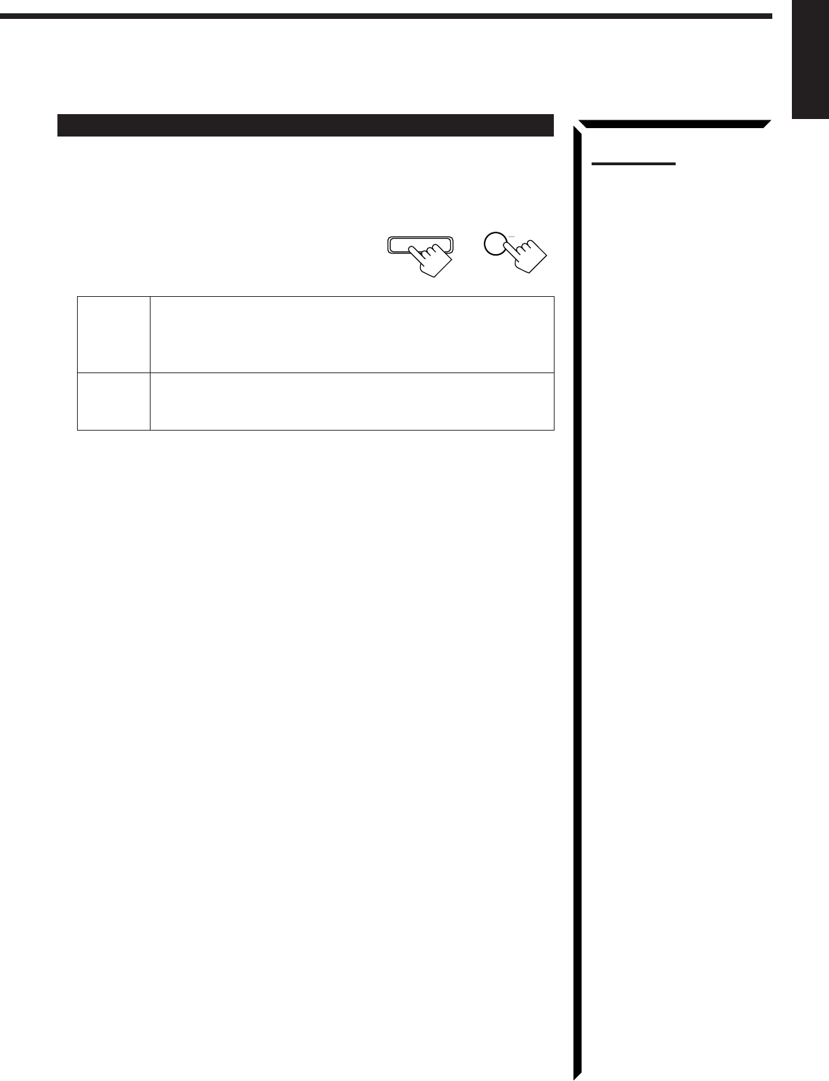
Using the One Touch Operation
On the front panel
only
:
To store the sound settings
1. Press ONE TOUCH OPERATION.
The ONE TOUCH OPERATION lamp lights up, then the
previously memorized settings are recalled.
2. Adjust the sound using the functions listed above.
The newly adjusted settings are memorized.
To recall the sound settings
With the ONE TOUCH OPERATION lamp lit, the settings for the
currently selected source is recalled when the source is selected.
To cancel the One Touch Operation function
Press ONE TOUCH OPERATION so that the lamp goes off.
(Even though the One Touch Operation function is canceled, the
recalled sound effects remain active.)
Note:
If the source is FM or AM, you
can assign a different setting for
each band.
ONE TOUCH OPERATION
ONE TOUCH OPERATION
EN14_23.RX-884P[U]/1.PM5 98.2.24, 9:03 PM23
24
English
Receiving Radio Broadcasts
You can browse through all the stations or use the preset function to go immediately to a particular
station.
IMPORTANT:
When using the Remote Control, check to see if its remote control
mode selector is set to the correct position:
To operate this receiver, set it to “AUDIO/TV/VCR” (except when
selecting the DBS tuner as the source).
Setting the AM Tuner Interval Spacing
Some countries space AM stations 9 kHz apart, and other countries use 10 kHz spacing.
When shipped, the spacing is set to 9 kHz.
On the front panel
only
:
To select the 10 kHz interval:
Be sure the receiver is turned off, but is plugged into
an AC outlet and POWER is pressed to set it in
the _ON position. Hold down TUNER PRESET
and press STANDBY/ON . “10K STEP” appears
on the display for about three seconds. Now the 10
kHz interval is selected.
To change back to the 9 kHz interval:
Be sure the receiver is turned off, but is plugged into
an AC outlet and POWER is pressed to set it in
the _ON position. Hold down FM MODE and press
STANDBY/ON . “9K STEP” appears on the
display for about three seconds. Now the 9 kHz
interval is selected.
Tuning in Stations Manually
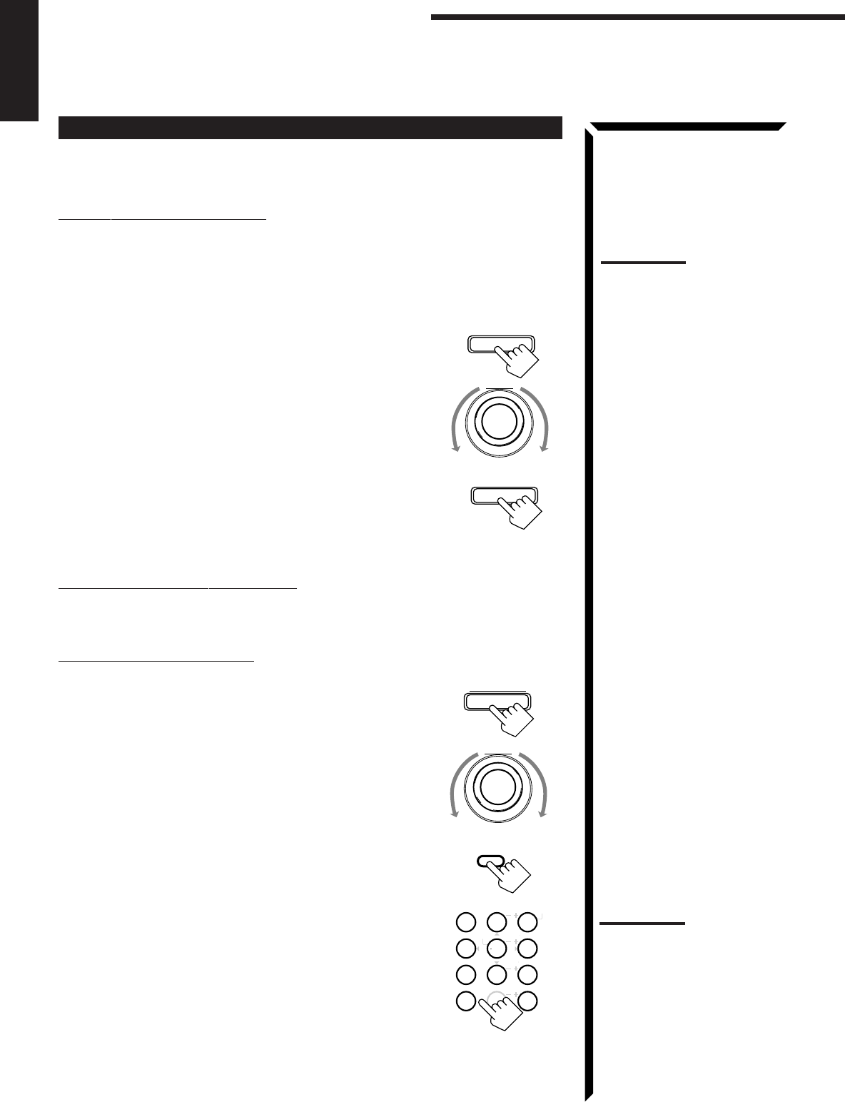
On the front panel:
1. Press FM/AM TUNING to select the band.
Each time you press the button, the band alternates between
FM and AM.
2. Turn MULTI JOG until you find the frequency you
want.
• Turning it clockwise increases the frequency.
• Turning it counterclockwise decreases the frequency.
From the remote control:
1. Press FM/AM to select the band.
Each time you press the button, the band alternates between
FM and AM.
2. Press TUNING DOWN or TUNING UP repeatedly
until you find the frequency you want.
AUDIO/TV
/VCR
CATV
/DBS
FM/AM TUNING
MULTI JOG
FM/AM
FF / ¢
4 / REW
TUNING DOWN
TUNING UP
Notes:
• When you turn MULTI JOG
quickly or hold the TUNING
UP or TUNING DOWN in step
2, the frequency keeps
changing until a station is
tuned in.
• When a station of sufficient
signal strength is tuned in, the
TUNED indicator lights up on
the display.
When an FM stereo program
is received, the STEREO
indicator also lights up.
and
and
STANDBY
STANDBY/ON
STANDBY
STANDBY/ON
FM MODE
TUNER PRESET
EN24_29.RX-884P[U]/1.PM5 98.2.23, 11:20 AM24
25
English
Using Preset Tuning
Once a station is assigned to a channel number, the station can be quickly tuned. You
can preset up to 40 stations at random.
To store the preset stations
On the front panel
only
:
1. Tune in the station you want to preset (see page 24).
If you want to store the FM reception mode for this station, select the FM reception
mode you want. See page 26 for details.
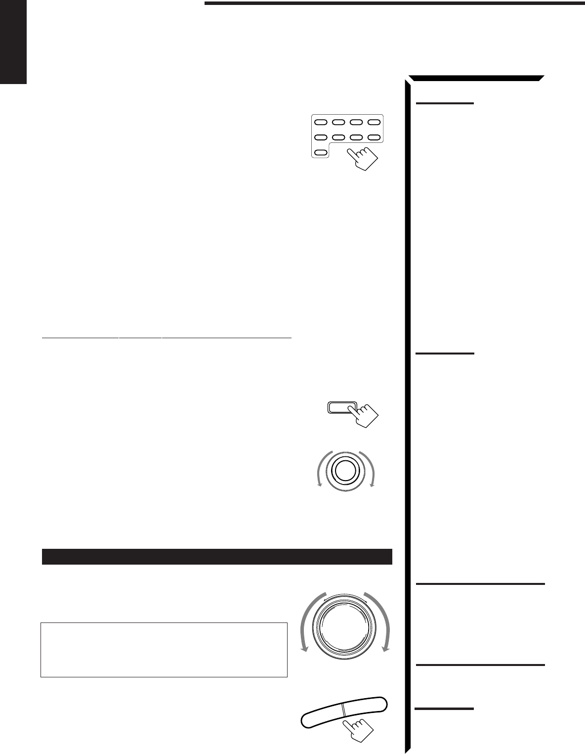
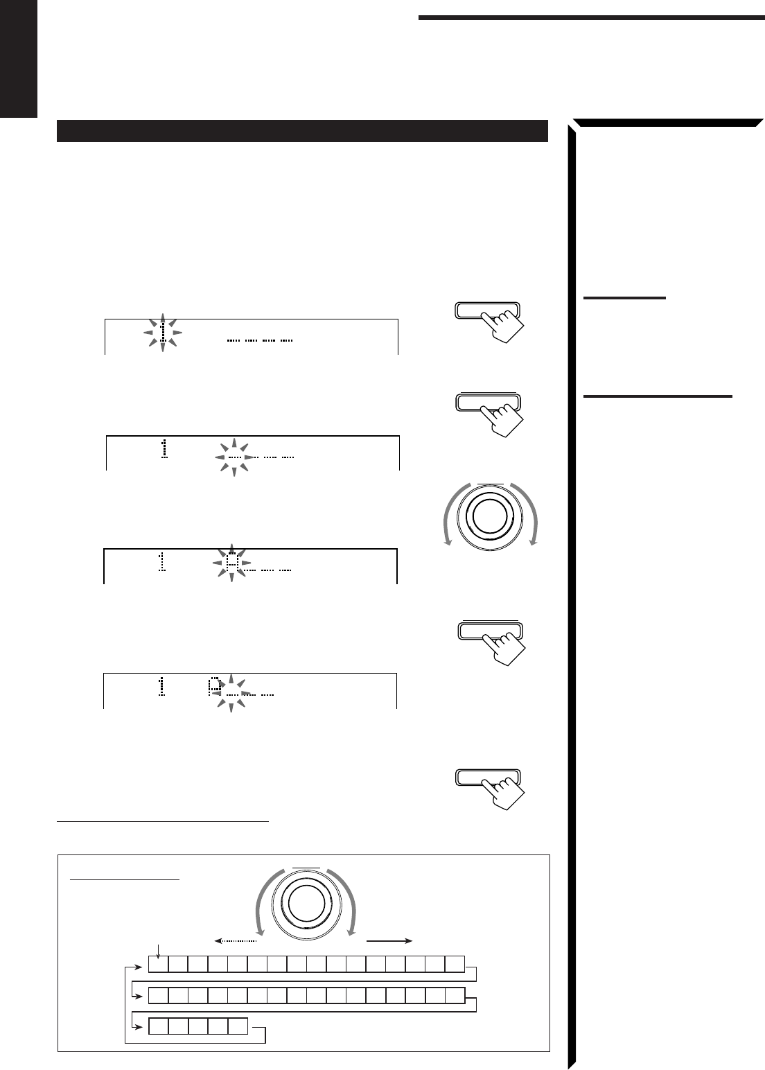
2. Press TUNER/SEA MEMORY.
“CH-” appears and the channel number position starts flashing
on the display for about 5 seconds.
3. Turn MULTI JOG to select a channel number while
the channel number position is flashing.
4. Press TUNER/SEA MEMORY again while the
selected channel number is flashing on the display.
The selected channel number stops flashing.
The station is assigned to the selected channel number.
5. Repeat steps 1 to 4 until you store all the stations you
want.
To erase a stored preset station
Storing a new station on a used number erases the previously stored one.
To tune in a preset station
On the front panel:
1. Press TUNER PRESET.
2. Turn MULTI JOG to select a preset channel.
From the remote control:
1. Press FM/AM.
Each time you press the button, the band alternates
between FM and AM.
2. Press 10 keys to select a preset channel number.
• For channel number 5, press 5.
• For channel number 15, press +10 then 5.
• For channel number 20, press +10 then 10.
• For channel number 30, press +10, +10, then 10.
MULTI JOG
FM/AM
MENU
TEST
REAR R
REAR L
SEA MODE SUBWOOFER
546
213
87
/P
9
0
+10
10
CNTRCNTR TONE
ENTER
EFFECT
FM MODE/MUTE
100+
RETURN
TUNER PRESET
Note:
When you use the 10 keys on
the remote control, be sure that
they are activated for tuner, not
for the CD and others. (See
page 58.)
TUNER/SEA MEMORY
MULTI JOG
TUNER/SEA MEMORY
Receiving Radio Broadcasts
Note:
You can use the 10 keys on the
remote control to select the
preset number. When using the
10 keys, be sure that they are
activated for tuner, not for the
CD and others. (See page 58.)
EN24_29.RX-884P[U]/1.PM5 98.2.23, 11:20 AM25
26
English
Selecting the FM Reception Mode
When an FM stereo broadcast is hard to receive or noisy, set the FM reception mode to
“MONO.” (When shipped from the factory, this mode has been set to “AUTO.”)
You can change the FM reception mode while receiving an FM broadcast.
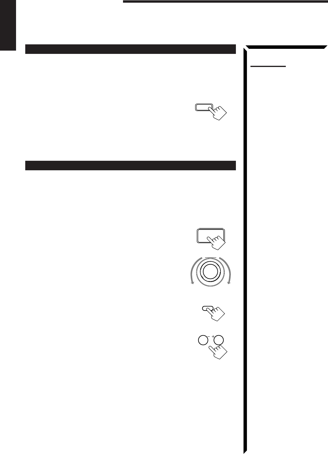
Press FM MODE on the front panel or FM MODE/
MUTE on the remote control.
Each time you press the button, the FM reception mode
alternates between “AUTO” and “MONO.”
AUTO: When a program is broadcasted in stereo, you will hear stereo
sound; when in monaural, you will hear monaural sounds. This
mode is also useful to suppress static noise between stations.
The MUTE AUTO indicator lights up on the display.
MONO: Reception will be improved although you will lose the stereo effect.
In this mode, you will hear noise while tuning into the stations.
The MUTE AUTO indicator goes off on the display.
FM MODE/MUTE
0
SUBWOOFER
FM MODE
Notes:
• You can store the FM
reception mode for each
preset station.
• When using the FM MODE/
MUTE button, be sure that the
10 keys are activated for
tuner, not for the CD and
others. (See page 58.)
EN24_29.RX-884P[U]/1.PM5 98.3.7, 0:17 PM26
27
English
Assigning Names to Preset Stations
You can assign a name of up to four characters to each preset station. When a preset
station is tuned in, its assigned name will appear on the display.
On the front panel
only
:
1. Tune in a preset station.
See page 25 for details.
2. Press TUNER/SEA MEMORY.
The preset channel number starts flashing for about 5 seconds.
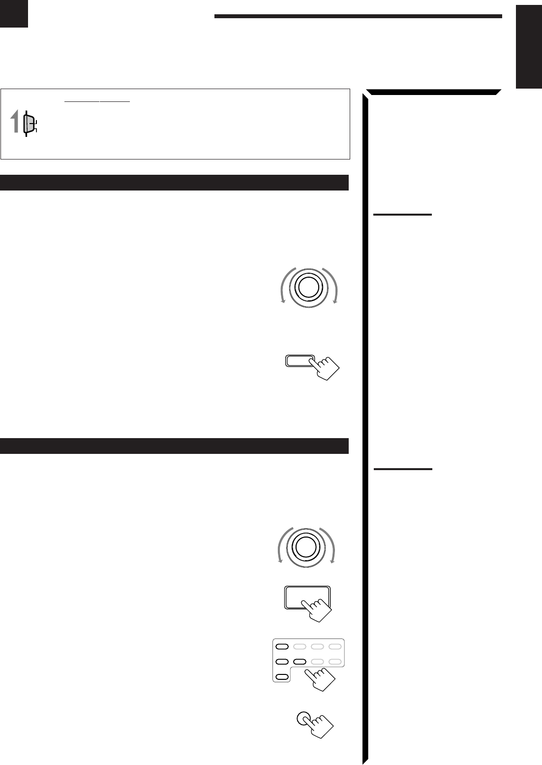
3. Press TUNER PRESET, while the preset channel number is
flashing.
The first character position starts flashing.
4. Turn MULTI JOG to select the first character, while
the first character position is flashing.
You can use characters listed below.
5. Press TUNER PRESET, while a character you want is
flashing.
The next (or previous) character position starts flashing.
6. Repeat steps 4 and 5 to enter up to four characters.
7. Press TUNER/SEA MEMORY while the last selected
character is flashing after you have assigned a name.
To erase the input characters
Insert spaces using the same procedure described above.
CH–
Available characters
Space
CBADEGFHIJKLMNO
SRQTUWVX
YZ01234P
87695
MULTI JOG
CH–
VOLUME
CH–
VOLUME
CH–
VOLUME
Note:
If you turn MULTI JOG while the
preset channel number is
flashing, you can change
the preset channel number.
TUNER/SEA MEMORY
MULTI JOG
TUNER PRESET
TUNER PRESET
TUNER/SEA MEMORY
Receiving Radio Broadcasts
Note on step 3 to 7:
You cannot select any entry
after the indication on the
display stops flashing.
In this case, repeat the
procedure from step 2 again.
EN24_29.RX-884P[U]/1.PM5 98.3.10, 11:16 AM27
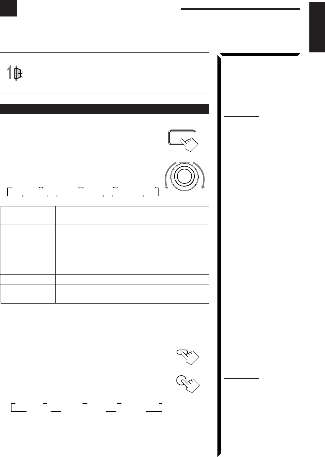
28
English
Using the SEA Modes
The SEA (Sound Effect Amplifier) modes give you control of the way your music sounds.
IMPORTANT:
When using the Remote Control, check to see if its remote control
mode selector is set to the correct position:
To operate this receiver, set it to “AUDIO/TV/VCR” (except when
selecting the DBS tuner as the source).
Selecting Your Favorite SEA Mode
On the front panel:
1. Press SEA MODE.
The display changes to show the current setting.
2. Turn MULTI JOG until the mode you want appears on the
display, while the indication of the previous step is still on
the display.
As you turn it, the SEA mode changes as follows:
SEA ROCK: Gives a heavy sound. Both high and low frequencies are
boosted.
SEA MUSICAL: Enhance the mid-frequency range, which the human voice is
mostly made up of.
SEA MOVIE: Adds breadth to sounds so you feel like you are in a movie
theater.
SEA COUNTRY: Enhances the high-frequency range so that instruments such
the violin and banjo are emphasized.
SEA JAZZ: Gives a feeling of a live atmosphere. Good for acoustic music.
SEA USERMODE: Your original SEA adjustment (see page 29).
SEA OFF: No SEA mode is applied (see below).
To cancel the SEA mode
Turn MULTI JOG until “SEA OFF” appears in step 2 above.
The SEA indicator goes off from the display.
From the remote control:
1. Press SOUND CONTROL.
10 keys are activated for sound adjustments.
2. Press SEA MODE repeatedly until the SEA mode you want
appears on the display.
Each time you press the button, the SEA mode changes
as follows:
To cancel the SEA mode
Press SEA MODE until “SEA OFF” appears in step 2 above.
The SEA indicator goes off from the display.
AUDIO/TV
/VCR
CATV
/DBS
Notes:
• The SEA modes cannot be
used for recording.
• When the SEA mode is turned
on, the SEA indicator lights up
on the display.
• When the SEA mode is used
with the DAP mode (see page
34), sounds may be distorted.
If this happens, turn off the
DAP mode or decrease the
effect level of the DAP mode.
SEA MODE
SEA COUNTRY
SEA JAZZ
SEA ROCK SEA MUSICAL SEA MOVIE
SEA USERMODESEA OFF
SOUND
CONTROL
10
SEA MODE
RETURN
SEA COUNTRY
SEA JAZZ
SEA ROCK SEA MUSICAL SEA MOVIE
SEA USERMODESEA OFF
Note:
When the SEA mode is turned
on, the SEA indicator lights up
on the display.
MULTI JOG
EN24_29.RX-884P[U]/1.PM5 98.2.24, 9:06 PM28
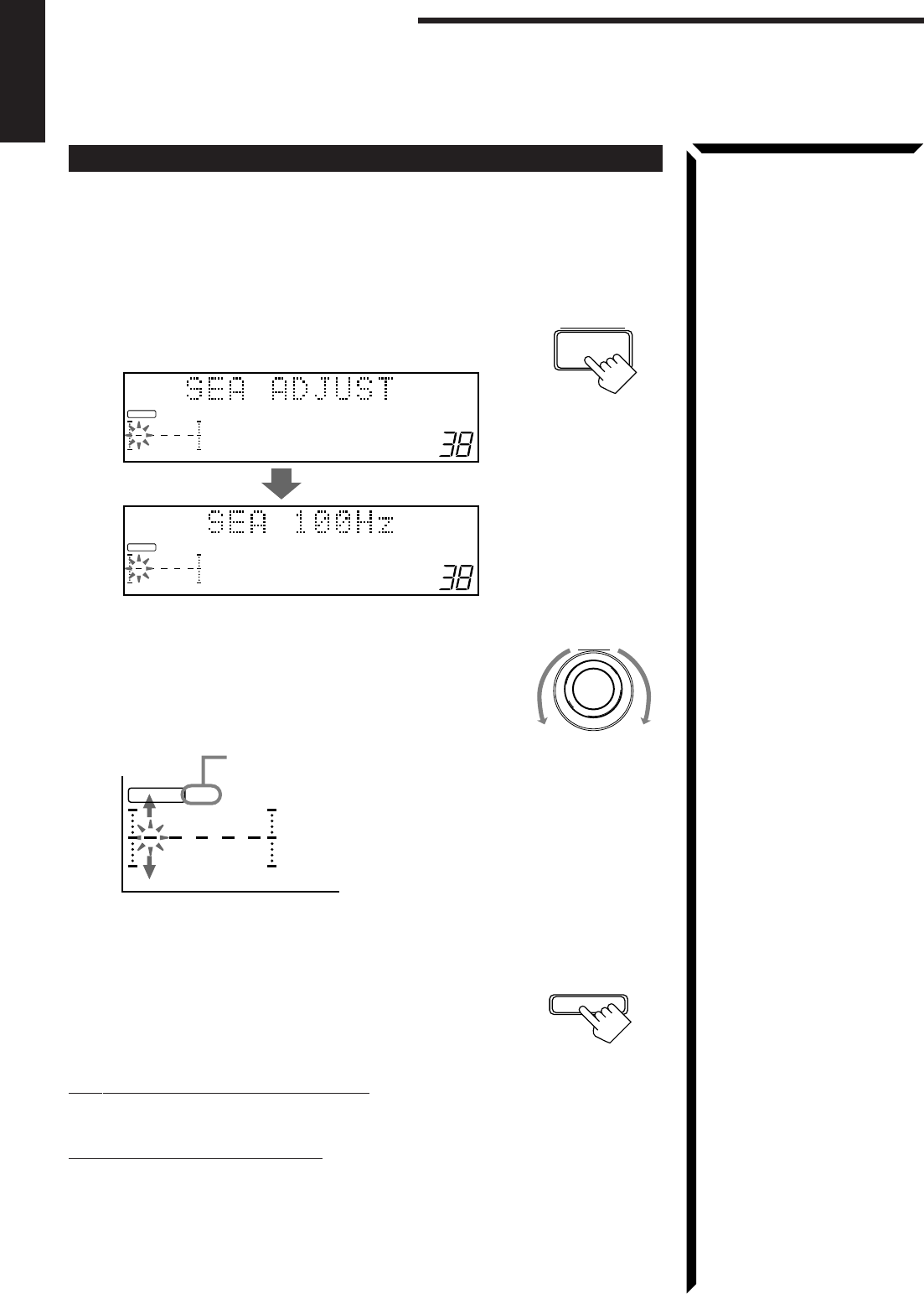
29
English
Creating Your Own SEA Mode
You can adjust and store your own SEA adjustment into memory (SEA USERMODE).
On the front panel
only
:
If you do not want to store your adjustment, but rather want to adjust the SEA
temporarily, skip step 4 below.
1. Press SEA ADJUST repeatedly until the frequency range
(100Hz, 1kHz or 10kHz) you want appears on the display.
2. Turn MULTI JOG to adjust the SEA level of the selected
frequency range, while the indication of the previous step is
still on the display.
• Turning it clockwise increases the level.
• Turning it counterclockwise decreases the level.
3. Repeat step 1 and 2 to adjust other frequency ranges if
necessary.
4. Press TUNER/SEA MEMORY, while the indication of the
previous step is still on the display.
Your adjustment is stored into the SEA USERMODE.
To recall your own SEA adjustment
See page 28.
To erase a stored adjustment
Storing a new adjustment into SEA USERMODE erases the previously stored one.
SEA ADJUST
MULTI JOG
100 1k 10k
VOLUME
FR
S E A
100 1k 10k
VOLUME
FR
S E A
Using the SEA Modes
100 1k 10k
FR
S E A
This FR means this adjustment can be
applied to the front speakers only
TUNER/SEA MEMORY
EN24_29.RX-884P[U]/1.PM5 98.3.11, 10:37 AM29

30
English
Using the DSP Modes
The built-in Surround Processor provides three types of the DSP (Digital Signal Processor) mode — 3D-
PHONIC mode, DAP (Digital Acoustic Processor) mode and Surround mode (Dolby Digital, Dolby Pro Logic
and JVC’s Theater Surround.)
On the 3D-PHONIC mode
The 3D-PHONIC mode gives you such a
nearly surround effect as it is reproduced
through the Dolby Surround decoder, which
is widely used to reproduce sounds with a
feeling of movement like those experienced
in movie theaters. The 3D-PHONIC mode is
the result of research on sound localization
technology carried out at JVC for many
years and makes it possible to reproduce the
surround sound with only two front
speakers.
On the DAP mode
The sound heard in a concert hall or club
consists of direct sound and indirect sound
— early reflections and reflections from
behind. Direct sounds reach the listener
directly without any reflection. On the other
hand, indirect sounds are delayed by the
distances of the ceiling and walls. These
direct sounds and indirect sounds are the
most important elements of the acoustic
surround effects. The DAP mode can create
these important elements, and gives you a
real “being there” feeling.
On Surround mode
With this receiver, you can use two types of
the surround mode.
Dolby Surround (Dolby Digital and
Dolby Pro Logic)
Used to watch the soundtracks of software
encoded with Dolby Digital (bearing the
mark
DIGITAL
) or with Dolby Surround
(bearing the mark
DOLBY SURROUND
).
Dolby Digital and Dolby Pro Logic can be
selected automatically according to
software played back.
JVC’s Theater Surround
In order to reproduce a more realistic sound field in your listening room while playing
soundtracks of software encoded with Dolby Digital (bearing the mark
DIGITAL
) or
with Dolby Surround (bearing the mark
DOLBY SURROUND
), Theater Surround has been
designed to create a real “being there” feeling.
Early reflections
Reflections from
behind
Direct sounds
Notes:
• The DSP modes has no effect
on monaural sources.
• You can not use the two types
of the DSP modes at the same
time.
Note:
To enjoy the software encoded
with Dolby Digital, you must
connect the source component
using the digital terminal on the
rear of this receiver.
Manufactured under license
from Dolby Laboratories.
“Dolby,” “Pro Logic,” the double-
D symbol are trademarks of
Dolby Laboratories. Confidential
Unpublished works. ©1992–
1997 Dolby Laboratories, Inc. All
rights reserved.
IMPORTANT:
When recording the digital
source, turn off the DSP mode.
EN30_42.RX-884P[U]/1.PM5 98.2.24, 9:29 PM30
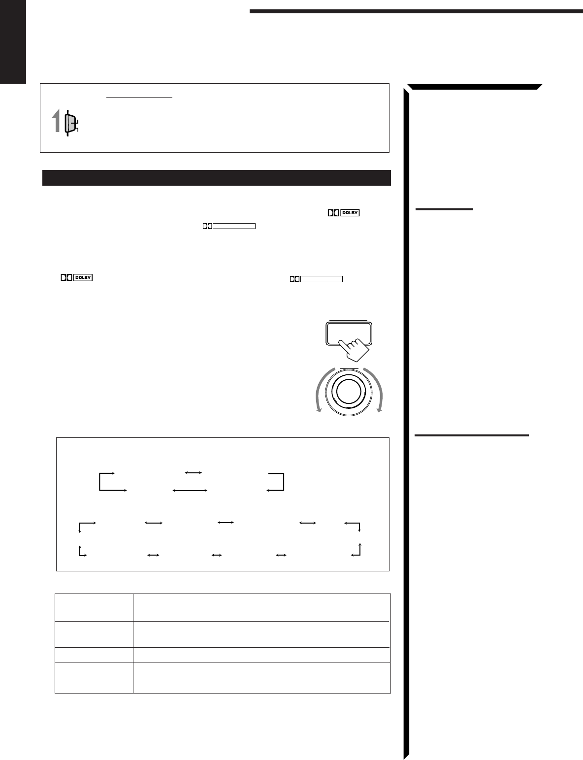
31
English
Using the DSP Modes
IMPORTANT:
When using the Remote Control, check to see if its remote control
mode selector is set to the correct position:
To operate this receiver, set it to “AUDIO/TV/VCR” (except when
selecting the DBS tuner as the source).
Using the 3D-PHONIC Modes
When using the 3D-PHONIC modes, you need only two front speakers to reproduce the
soundtracks of software encoded with Dolby Digital (bearing the mark
DIGITAL
) or
with Dolby Surround (bearing the mark
DOLBY SURROUND
).
On the front panel:
1. Select and play the source encoded with Dolby Digital (bearing the mark
DIGITAL
) or with Dolby Surround (bearing the mark
DOLBY SURROUND
).
• When you play back the source encoded with Dolby Digital and select the digital
input for that source, the Ÿ DIGITAL indicator lights up on the display.
2. Press DSP MODE.
The current DSP mode appears on the display.
3. Turn MULTI JOG until the mode — 3D ACTION (or 3D
DIGITAL), 3D DRAMA, or 3D THEATER — you want
appears on the display, while the indication of the previous
step is still on the display.
As you turn it, the DSP modes change as follows (the 3D-
PHONIC and DSP indicators also light up on the display):
When the digital input is selected to play the source encoded with Dolby
Digital:
For other sources:
3D ACTION: Best for action and war movies — where the action is fast and
explosive.
3D DRAMA: Best for dramas and romantic movies — where the action is
slow and soft.
3D THEATER: Reproduces the sound field of a theater.
3D DIGITAL: Reproduces multi-sound source encoded with Dolby Digital.
DSP OFF
:
No DSP mode is applied.
For the other modes, see pages 34 and 39.
If you need to make any adjustment, go to the following steps.
AUDIO/TV
/VCR
CATV
/DBS
MULTI JOG
DSP MODE
Notes:
• To enjoy the software
encoded with Dolby Digital,
you must connect the source
component using the digital
terminal on the rear of this
receiver.
• The 3D-PHONIC mode is not
used with the other DSP
modes such as the DAP
mode and the Surround
mode. When the 3D-PHONIC
mode is turned on, the other
DSP mode, if used, will be
turned off.
Notes on the indications:
• The indicator of the selected
DSP mode also lights up on
the display while selecting.
• The PRO LOGIC indicator
lights up when the Dolby Pro
Logic decoder built in this
receiver is activated.
• The Dolby Pro Logic decoder
is used not only for the analog
sources but also for the
sources encoded with Dolby
Digital in the following cases:
– When only front channel
signals are encoded.
– When front channel and
monaural rear channel
signals are encoded.
While the Dolby Pro Logic is
activated for this type of Dolby
Digital source, the
Ÿ
DIGITAL
indicator goes off.
DIG-THEATER HEADPHONE
3D DIGITAL
DSP OFF
HALL
DANCE CLUB
LIVE CLUBTHEATER
3D ACTION HEADPHONE
3D DRAMA
PAVILION
3D THEATER
DSP OFF
EN30_42.RX-884P[U]/1.PM5 98.2.25, 11:42 AM31

32
English
4. Press BALANCE/SURROUND ADJUST repeatedly until
“DSP EFFECT” appears on the display.
The display changes to show the current setting.
5. Turn MULTI JOG to select the effect level, while the indication of
the previous step is still on the display.
As you turn it, the effect level changes as follows:
As the number increases, the selected 3D-PHONIC mode
becomes stronger.
To cancel the 3D-PHONIC mode
Turn MULTI JOG until “DSP OFF” appears in step 3.
The 3D-PHONIC and DSP indicators go off from the display.
Note:
Once you have adjusted the 3D-
PHONIC modes, it is memorized
for each 3D-PHONIC mode.
BALANCE/SURROUND
ADJUST
MULTI JOG
DSP EFFECT 1 DSP EFFECT 2
DSP EFFECT 4
DSP EFFECT 3
DSP EFFECT 5
EN30_42.RX-884P[U]/1.PM5 98.3.11, 9:35 PM32

33
English
From the remote control:
1. Select and play the source encoded with Dolby Digital (bearing the mark
DIGITAL
) or with Dolby Surround (bearing the mark
DOLBY SURROUND
).
• When you play back the source encoded with Dolby Digital and select the digital
input for that source, the Ÿ DIGITAL indicator lights up on the display.
2. Press SURROUND MODE repeatedly until the mode — 3D
ACTION (or 3D DIGITAL), 3D DRAMA, or 3D THEATER
— you want appears on the display.
Each time you press the button, the DSP modes change as
follows (the 3D-PHONIC and DSP indicators also light up
on the display):
When the digital input is selected to play the source encoded with Dolby
Digital:
For other sources:
3. Press SOUND CONTROL.
10 keys are activated for sound adjustments.
4. Press EFFECT to select the effect level.
Each time you press the button, the effect level changes as follows:
As the number increases, the selected 3D-PHONIC mode becomes
stronger.
To cancel the 3D-PHONIC mode
Press SURROUND MODE repeatedly until “OFF” appears.
The 3D-PHONIC and DSP indicators go off from the display.
Note:
The 3D-PHONIC mode is not
used with the other DSP modes
such as the DAP mode and the
Surround mode. When the 3D-
PHONIC mode is turned on, the
other DSP mode, if used, will be
turned off.
SURROUND
MODE
HALL
DANCE CLUB
LIVE CLUB
THEATER
PRO LOGIC
3D ACTION HEADPHONE
3D DRAMA
PAVILION
3D THEATER
OFF
SOUND
CONTROL
7
/P
EFFECT
DSP EFFECT 1 DSP EFFECT 2
DSP EFFECT 4
DSP EFFECT 3
DSP EFFECT 5
Note:
Once you have adjusted the 3D-
PHONIC modes, it is memorized
for each 3D-PHONIC mode.
Using the DSP Modes
Notes on the indications:
• The indicator of the selected
DSP mode also lights up on
the display while selecting.
• The PRO LOGIC indicator
lights up when the Dolby Pro
Logic decoder built in this
receiver is activated.
• The Dolby Pro Logic decoder
is used not only for the analog
sources but also for the
sources encoded with Dolby
Digital in the following cases:
– When only front channel
signals are encoded.
– When front channel and
monaural rear channel
signals are encoded.
While the Dolby Pro Logic is
activated for this type of Dolby
Digital source, the
Ÿ
DIGITAL
indicator goes off.
DOLBY DIGITAL DIG-THEATER
HEADPHONE
3D DIGITAL
OFF
EN30_42.RX-884P[U]/1.PM5 98.2.24, 9:29 PM33

34
English
Notes:
• The DAP mode is not used
with the other DSP modes
such as the 3D-PHONIC
mode and the Surround
mode. When the DAP mode
is turned on, the other DSP
mode, if used, will be turned
off.
• When the DAP mode is used
with the SEA mode (see page
28), sounds may be distorted.
If this happens, turn off the
SEA mode.
Using the DAP Modes
You can use five DAP modes — “Live Club, Dance Club, Hall, Pavilion, and
Headphones” for any source.
Among the DAP modes, “Headphones” is very special. It can create the same stereo
sound as you listen through the speakers off air while listening to a source using
headphones. So, you can feel as if you were not using the headphones and listening to
music in a room.
If the digital input is selected to play the source encoded with Dolby Digital, you can
only select “Headphones.”
On the front panel:
1. Press DSP MODE.
The current DSP mode appears on the display.
2. Turn MULTI JOG until the mode (LIVE CLUB, DANCE
CLUB, HALL, PAVILION, or HEADPHONE) you want
appears on the display, while the indication of the previous
step is still on the display.
The DSP indicator also lights up on the display.
As you turn it, the DSP modes change as follows:
When the digital input is selected to play the source encoded with Dolby
Digital:
LIVE CLUB: Gives the feeling of a live music club with a low ceiling.
DANCE CLUB: Gives a throbbing bass beat.
HALL: Gives clear vocal and the feeling of a concert hall.
PAVILION: Gives the spacious feeling of a pavilion with a high ceiling.
HEADPHONE:
Gives a spacious stereo effect when listening with headphones.
DSP OFF
:
No DSP mode is applied.
For the other modes, see pages 31 and 39.
If you need to make any adjustment, go to the following steps.
3. Adjust the speaker output levels as follows.
1) Press BALANCE/SURROUND ADJUST repeatedly
until one of the indications appears on the display.
“REAR L LEVEL”: To adjust the left speaker level.
“REAR R LEVEL”: To adjust the right speaker level.
2) Turn MULTI JOG to adjust the selected speaker output
level (from –10 dB to +10 dB), while the indication of the
previous step is still on the display.
3) Repeat 1) and 2) to adjust the other speaker output
levels.
Note:
The indicator of the selected
DSP mode also lights up on the
display while selecting.
HALL
DANCE CLUB
LIVE CLUBTHEATER
3D ACTION HEADPHONE
3D DRAMA
PAVILION
3D THEATER
DSP OFF
DIG-THEATER HEADPHONE
3D DIGITAL
DSP OFF
Note:
When you select
“HEADPHONE,” you cannot go
to the following steps. No
adjustments can be made for
“HEADPHONE.”
Note:
You cannot adjust the rear
speaker levels when “REAR
SPK” is set to “NONE” (see
page 20).
MULTI JOG
MULTI JOG
DSP MODE
BALANCE/SURROUND
ADJUST
Continued to the next page.
EN30_42.RX-884P[U]/1.PM5 98.3.10, 5:21 PM34

35
English
4. Adjust the effect level.
1) Press BALANCE/SURROUND ADJUST repeatedly
until “DSP EFFECT” appears on the display.
2) Turn MULTI JOG to select the effect level, while the
indication of the previous step is still on the display.
As you turn it, the effect level changes as follows:
As the number increases, the selected DAP mode
becomes stronger.
To cancel the DAP mode
Turn MULTI JOG until “DSP OFF” appears in step 2.
The DSP indicator goes off from the display.
From the remote control:
1. Press SURROUND MODE repeatedly until the mode you
want appears on the display.
The DSP indicator also lights up on the display.
Each time you press the button, the DSP modes change as follows (the indicator
of the selected DSP mode also lights up on the display):
When the digital input is selected to play the source encoded with Dolby
Digital:
If you need to make any adjustment, go to the following steps.
2. Press SOUND CONTROL.
10 keys are activated for sound adjustments.
3. Adjust the speaker output levels as follows:
• To adjust the left rear speaker level, press REAR•L +/–.
• To adjust the right rear speaker level, press REAR•R +/–.
4. Press EFFECT to select the effect level.
Each time you press the button, the effect level changes as
follows:
As the number increases, the selected DAP mode becomes
stronger.
To cancel the DAP mode
Press SURROUND MODE repeatedly until “OFF” appears.
The DSP indicator goes off from the display.
BALANCE/SURROUND
ADJUST
Note:
Once you have adjusted the
DAP modes, the adjustment is
memorized for each DAP mode.
Note:
The DAP mode is not used with
the other DSP modes such as
the 3D-PHONIC mode and the
Surround mode. When the DAP
mode is turned on, the other
DSP mode, if used, will be
turned off.
SURROUND
MODE
MULTI JOG
DSP EFFECT 1 DSP EFFECT 2
DSP EFFECT 4
DSP EFFECT 3
DSP EFFECT 5
HALL
DANCE CLUB
LIVE CLUB
THEATER
PRO LOGIC
3D ACTION HEADPHONE
3D DRAMA
PAVILION
3D THEATER
OFF
Note:
Once you have adjusted the
DAP modes, the adjustment is
memorized for each DAP mode.
DSP EFFECT 1 DSP EFFECT 2
DSP EFFECT 4
DSP EFFECT 3
DSP EFFECT 5
Using the DSP Modes
DOLBY DIGITAL DIG-THEATER
HEADPHONE
3D DIGITAL
OFF
Note:
When you select
“HEADPHONE,” you cannot go
to the following steps. No
adjustments can be made for
“HEADPHONE.”
REAR R
89
REAR L
56
ENTER
Note:
You cannot adjust the rear
speaker levels when “REAR
SPK” is set to “NONE” (see
page 20).
SOUND
CONTROL
7
/P
EFFECT
EN30_42.RX-884P[U]/1.PM5 98.2.24, 9:30 PM35
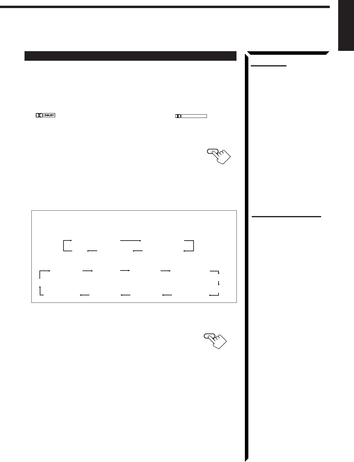
36
English
Using the Dolby Digital and Dolby Pro Logic Modes
Once you have adjusted the Dolby Digital and Dolby Pro Logic modes, this receiver
memorizes adjustment for each mode.
To activate the Dolby Digital and Dolby Pro Logic modes, follow the procedure below.
From the remote control:
1. Select and play the source encoded with Dolby Digital (bearing the mark
DIGITAL
) or with Dolby Surround (bearing the mark
DOLBY SURROUND
).
• When you play back the source encoded with Dolby Digital and select the digital
input for that source, the Ÿ DIGITAL indicator lights up on the display.
2. Press SURROUND MODE repeatedly until “PRO LOGIC”
or “DOLBY DIGITAL” appears on the display.
Dolby Digital or Dolby Pro Logic is automatically selected
according to the source being played back.
When Dolby Pro Logic is selected, the lamp on the DOLBY SURROUND button
(on the front panel) lights red.
When Dolby Digital is selected, the lamp on the DOLBY SURROUND button (on
the front panel) lights green.
Each time you press the button, the DSP modes change as follows:
When the digital input is selected to play the source encoded with Dolby
Digital:
For other sources:
If you need to make any adjustment, go to the following steps.
3. Press SOUND CONTROL.
10 keys are activated for sound adjustments.
Notes:
• To enjoy the software encoded
with Dolby Digital, you must
connect the source
component using the digital
terminal on the rear of this
receiver.
• When the signals come into
this receiver through the
analog connection from the
source component, “PRO
LOGIC” is automatically
selected.
• The Surround mode is not
used with the other DSP
modes such as the DAP mode
and 3D-PHONIC mode. When
the Surround mode is turned
on, the other DSP mode, if
used, will be turned off.
SURROUND
MODE
Notes on the indications:
• The PRO LOGIC indicator
lights up when the Dolby Pro
Logic decoder built in this
receiver is activated.
• The Dolby Pro Logic decoder
is used not only for the analog
sources but also for the
sources encoded with Dolby
Digital in the following cases:
– When only front channel
signals are encoded.
– When front channel and
monaural rear channel
signals are encoded.
While the Dolby Pro Logic is
activated for this type of Dolby
Digital source, the
Ÿ
DIGITAL
indicator goes off.
DOLBY DIGITAL DIG-THEATER
HEADPHONE
3D DIGITAL
OFF
HALL
DANCE CLUB
LIVE CLUB
THEATER
PRO LOGIC
3D ACTION HEADPHONE
3D DRAMA
PAVILION
3D THEATER
OFF
SOUND
CONTROL
Continued to the next page.
EN30_42.RX-884P[U]/1.PM5 98.2.24, 9:30 PM36

37
English
Using the DSP Modes
(Left front speaker) (Center speaker) (Right front speaker)
(Left rear speaker) (Right rear speaker)
TEST TONE L TEST TONE C TEST TONE R
TEST TONE RS
TEST TONE LS
TEST
4
The speaker indicators also light on the display while the test tone
comes out of the speakers.
L: Lights when the test tone comes out of the left front speaker.
C: Lights when the test tone comes out of the center speaker.
R: Lights when the test tone comes out of the right front speaker.
RS: Lights when the test tone comes out of the right rear speaker.
LS: Lights when the test tone comes out of the left rear speaker.
C
LS
L
RS
R
Notes:
• No test tone comes out of the
center speakers when
“CENTER SPK” is set to
“NONE” (see page 20).
• No test tone comes out of the
rear speakers when “REAR
SPK” is set to “NONE” (see
page 20).
• If the TV is turned on and the
proper video input is selected
on the TV, the test tone
screen will appear on the TV.
REAR L
56
ENTER
CNTR
23
MENU
REAR R
89
TEST
4
CNTR TONE
1
4. Press TEST to start checking the speaker output balance.
“TEST TONE L” starts flashing on the display, and a test
tone comes out of the speakers in the following order:
IMPORTANT:
• Output the test tone while playing back an audio source.
With the DVD digital input selected as the source, no test tone may come out while
no signal is input to this receiver.
• Test tone comes out even while playing back a source encoded with Dolby Digital. In
this case, the PRO LOGIC indicator lights up on the display.
5. Adjust the speaker output levels as follows:
• To adjust the center speaker level, press CNTR +/–.
• To adjust the left rear speaker level, press REAR•L +/–.
• To adjust the right rear speaker level, press REAR•R +/–.
6. Press TEST again to stop the test tone.
7. Press CNTR TONE to select the center tone level you want.
The center tone adjustment affects the mid-frequency
range, which the human voice is mostly made up of.
Each time you press the button, the display changes to
show the following:
Adjusted level are also shown on the equalizer display.
To make the dialogue clearer, select “SHARP1” (little) or “SHARP2” (much).
To make the dialogue softer, select “SOFT1” (little) or “SOFT2” (much).
When “FLAT” is selected, no adjustment is applied.
To cancel the Surround mode
Press SURROUND MODE repeatedly until “OFF” appears.
SHARP1 SHARP2FLATSOFT2 SOFT1
CNTR
100 1k 10k
S E A
This CNTR means this adjustment can be
applied to the center speaker only.
(Example: When “FLAT” is selected.)
Note:
The center tone cannot be
adjusted when “CENTER SPK”
is set to “NONE” (see page 20).
Notes:
• You can adjust the speaker
output levels and center tone
without outputting the test
tone.
• You cannot adjust the center
speaker output level when
“CENTER SPK” is set to
“NONE” (see page 20).
• You cannot adjust the rear
speaker levels when “REAR
SPK” is set to “NONE” (see
page 20).
EN30_42.RX-884P[U]/1.PM5 98.2.24, 9:30 PM37

38
English
Notes:
• To enjoy the software encoded
with Dolby Digital, you must
connect the source
component using the digital
terminal on the rear of this
receiver.
• When the signals come into
this receiver through the
analog connection from the
source component, “PRO
LOGIC” is automatically
selected.
• The Surround mode is not
used with the other DSP
modes such as the DAP mode
and 3D-PHONIC mode. When
the Surround mode is turned
on, the other DSP mode, if
used, will be turned off.
On the front panel:
You can also use the buttons on the front panel to adjust the Dolby Digital and Dolby
Pro Logic modes. However, no test tone is available when using the buttons on the front
panel. So, make adjustments while listening to the sound of the source played back.
1. Select and play the source encoded with Dolby Digital (bearing the mark
DIGITAL
) or with Dolby Surround (bearing the mark
DOLBY SURROUND
).
• When you play back the source encoded with Dolby Digital and select the digital
input for that source, the Ÿ DIGITAL indicator lights up on the display.
2. Press DOLBY SURROUND so that the lamp on the button
lights up.
“SURROUND ON” appears on the display.
Dolby Digital or Dolby Pro Logic is automatically selected
according to the source being played back.
When Dolby Pro Logic is selected, the lamp on the DOLBY SURROUND button
lights red.
When Dolby Digital is selected, the lamp on the DOLBY SURROUND button lights
green.
If you need to make any adjustment, go to the following steps.
3. Adjust the speaker output levels as follows.
1) Press BALANCE/SURROUND ADJUST repeatedly
until one of the indications appears on the display.
“CENTER LEVEL”: To adjust the center speaker level.
“REAR L LEVEL”: To adjust the left speaker level.
“REAR R LEVEL”: To adjust the right speaker level.
2) Turn MULTI JOG to adjust the selected speaker output
level (from –10 dB to +10 dB), while the indicator of the
previous step is still on the display.
3) Repeat 1) and 2) to adjust the other speaker output
levels.
4. Press BALANCE/SURROUND ADJUST repeatedly until
“CENTER TONE” appears on the display.
The display changes to show the current setting.
5. Turn MULTI JOG to select the center tone level you want,
while the indication of the previous step is still on the
display.
The center tone adjustment affects the mid-frequency
range, which the human voice is mostly made up of.
As you turn it, the display changes to show the
following:
To make the dialogue clearer, select “SHARP1” (little) or “SHARP2” (much).
To make the dialogue softer, select “SOFT1” (little) or “SOFT2” (much).
When “FLAT” is selected, no adjustment is applied.
To cancel the Surround mode
Press DOLBY SURROUND again so that “SURROUND OFF” appears.
MULTI JOG
BALANCE/SURROUND
ADJUST
DOLBY SURROUND
BALANCE/SURROUND
ADJUST
MULTI JOG
Notes:
• You cannot adjust the center
speaker level when “CENTER
SPK” is set to “NONE” (see
page 20).
• You cannot adjust the rear
speaker levels when “REAR
SPK” is set to “NONE” (see
page 20).
SHARP1 SHARP2FLATSOFT2 SOFT1
Notes on the indications:
• The PRO LOGIC indicator
lights up when the Dolby Pro
Logic decoder built in this
receiver is activated.
• The Dolby Pro Logic decoder
is used not only for the analog
sources but also for the
sources encoded with Dolby
Digital in the following cases:
– When only front channel
signals are encoded.
– When front channel and
monaural rear channel
signals are encoded.
While the Dolby Pro Logic is
activated for this type of Dolby
Digital source, the
Ÿ
DIGITAL
indicator goes off.
EN30_42.RX-884P[U]/1.PM5 98.3.11, 4:03 PM38
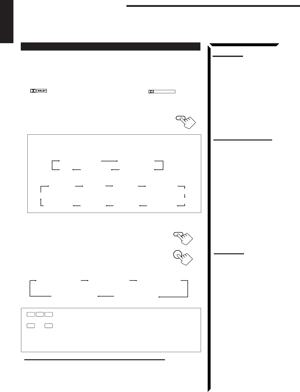
39
English
Using the Theater Surround Mode
Once you have adjusted the Theater Surround mode, this receiver memorizes the
adjustment. To activate the Theater Surround mode, follow the procedure below.
From the remote control:
1. Select and play the source encoded with Dolby Digital (bearing the mark
DIGITAL
) or with Dolby Surround (bearing the mark
DOLBY SURROUND
).
• When you play back the source encoded with Dolby Digital and select the digital
input for that source, the Ÿ DIGITAL indicator lights up on the display.
2. Press SURROUND MODE repeatedly until “THEATER”
or “DIG-THEATER” appears on the display.
The DSP and THEATER indicators also light up on the display.
Each time you press the button, the DSP modes change as follows:
When the digital input is selected to play the source encoded with Dolby
Digital:
For other sources:
If you need to make any adjustment, go to the following steps.
3. Press SOUND CONTROL.
10 keys are activated for sound adjustments.
4. Press TEST to start checking the speaker output balance.
“TEST TONE L” starts flashing on the display, and a test
tone comes out of the speakers in the following order:
Notes:
• To enjoy the software encoded
with Dolby Digital, you must
connect the source
component using the digital
terminal on the rear of this
receiver.
• The Surround mode is not
used with the other DSP
modes such as the DAP mode
and 3D-PHONIC mode. When
the Surround mode is turned
on, the other DSP mode, if
used, will be turned off.
SURROUND
MODE
Using the DSP Modes
Notes on the indications:
• The PRO LOGIC indicator
lights up when the Dolby Pro
Logic decoder built in this
receiver is activated.
• The Dolby Pro Logic decoder
is used not only for the analog
sources but also for the
sources encoded with Dolby
Digital in the following cases:
– When only front channel
signals are encoded.
– When front channel and
monaural rear channel
signals are encoded.
While the Dolby Pro Logic is
activated for this type of Dolby
Digital source, the
Ÿ
DIGITAL
indicator goes off.
DOLBY DIGITAL DIG-THEATER
HEADPHONE
3D DIGITAL
OFF
HALL
DANCE CLUB
LIVE CLUB
THEATER
PRO LOGIC
3D ACTION HEADPHONE
3D DRAMA
PAVILION
3D THEATER
OFF
(Left front speaker) (Center speaker) (Right front speaker)
(Left rear speaker) (Right rear speaker)
The speaker indicators also light on the display while the test tone
comes out of the speakers.
L: Lights when the test tone comes out of the left front speaker.
C: Lights when the test tone comes out of the center speaker.
R: Lights when the test tone comes out of the right front speaker.
RS: Lights when the test tone comes out of the right rear speaker.
LS: Lights when the test tone comes out of the left rear speaker.
C
LS
L
RS
R
TEST TONE L TEST TONE C TEST TONE R
TEST TONE RS
TEST TONE LS
IMPORTANT:
• Output the test tone while playing back an audio source.
With the DVD digital input selected as the source, no test tone may come out while
no signal is input to this receiver.
• Test tone comes out even while playing back a source encoded with Dolby Digital. In
this case, the PRO LOGIC indicator lights up on the display.
Notes:
• No test tone comes out of the
center speakers when
“CENTER SPK” is set to
“NONE” (see page 20).
• No test tone comes out of the
rear speakers when “REAR
SPK” is set to “NONE” (see
page 20).
• If the TV is turned on and the
proper video input is selected
on the TV, the test tone
screen will appear on the TV.
TEST
4
SOUND
CONTROL
EN30_42.RX-884P[U]/1.PM5 98.2.25, 11:52 AM39
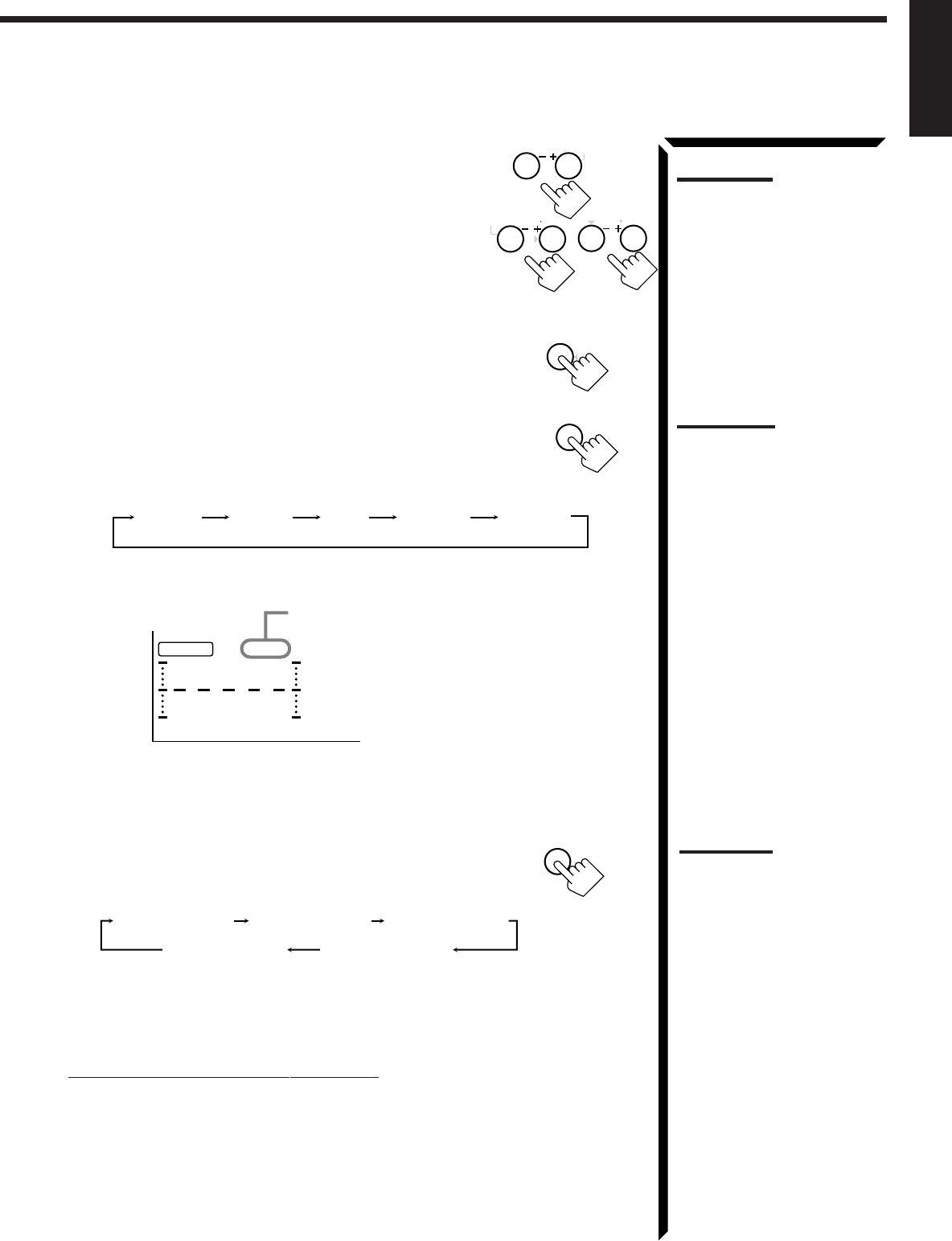
40
English
5. Adjust the speaker output levels as follows:
• To adjust the center speaker level, press CNTR +/–.
• To adjust the left rear speaker level, press REAR•L +/–.
• To adjust the right rear speaker level, press REAR•R +/–.
6. Press TEST again to stop the test tone.
7. Press CNTR TONE to select the center tone level you want.
The center tone adjustment affects the mid-frequency
range, which the human voice is mostly made up of.
Each time you press the button, the display changes to
show the following:
Adjusted level are also shown on the on the equalizer
display.
To make the dialogue clearer, select “SHARP1” (little) or “SHARP2” (much).
To make the dialogue softer, select “SOFT1” (little) or “SOFT2” (much).
When “FLAT” is selected, no adjustment is applied.
8. Press EFFECT to select the effect level.
Each time you press the button, the effect level changes
as follows:
As the number increases, the surround effect becomes
stronger.
To cancel the Theater Surround mode
Press SURROUND MODE repeatedly until “OFF” appears.
The DSP and THEATER indicators goes off.
Notes:
• You can adjust the speaker
output levels and center tone
without outputting the test
tone.
• You cannot adjust the center
speaker level when “CENTER
SPK” is set to “NONE” (see
page 20).
• You cannot adjust the rear
speaker levels when “REAR
SPK” is set to “NONE” (see
page 20).
CNTR
23
MENU
REAR L
56
ENTER
REAR R
89
Note:
The center tone cannot be
adjusted when “CENTER SPK”
is set to “NONE” (see page 20).
CNTR TONE
1
TEST
4
SHARP1 SHARP2FLATSOFT2 SOFT1
CNTR
100 1k 10k
S E A
This CNTR means this adjustment can be
applied to the center speaker only.
(Example: When “FLAT” is selected.)
7
/P
EFFECT
DSP EFFECT 1 DSP EFFECT 2
DSP EFFECT 4
DSP EFFECT 3
DSP EFFECT 5
Note:
You cannot adjust the effect
level when “REAR SPK” is set
to “NONE” (see page 20).
EN30_42.RX-884P[U]/1.PM5 98.2.24, 9:30 PM40
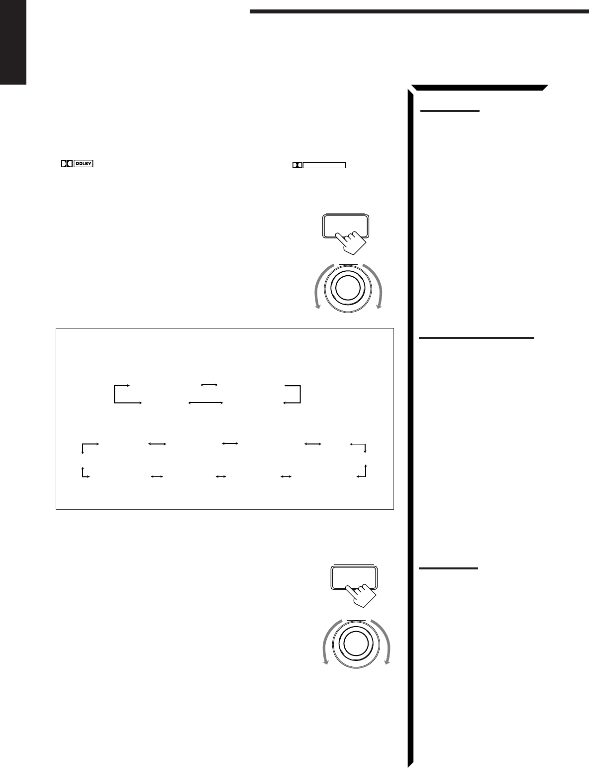
41
English
Notes:
• To enjoy the software encoded
with Dolby Digital, you must
connect the source
component using the digital
terminal on the rear of this
receiver.
• The Surround mode is not
used with the other DSP
modes such as the DAP mode
and 3D-PHONIC mode. When
the Surround mode is turned
on, the other DSP mode, if
used, will be turned off.
On the front panel:
You can also use the buttons on the front panel to adjust the Theater Surround mode.
However, no test tone is available when using the buttons on the front panel. So, make
adjustments while listening to the sound of the source played back.
1. Select and play the source encoded with Dolby Digital (bearing the mark
DIGITAL
) or with Dolby Surround (bearing the mark
DOLBY SURROUND
).
• When you play back the source encoded with Dolby Digital and select the digital
input for that source, the Ÿ DIGITAL indicator lights up on the display.
2. Press DSP MODE.
The current DSP mode appears on the display.
3. Turn MULTI JOG until “THEATER” or “DIG-
THEATER” appears on the display, while the indication of
the previous step is still on the display.
The DSP and THEATER indicators also light up on the display.
As you turn it, the DSP modes change as follows:
When the digital input is selected to play the source encoded with Dolby
Digital:
For other sources:
If you need to make any adjustment, go to the following steps.
4. Adjust the speaker output levels as follows.
1) Press BALANCE/SURROUND ADJUST repeatedly
until one of the indications appears on the display.
“CENTER LEVEL”: To adjust the center speaker level.
“REAR L LEVEL”: To adjust the left speaker level.
“REAR R LEVEL”: To adjust the right speaker level.
2) Turn MULTI JOG to adjust the selected speaker output
level (from –10 dB to +10 dB), while the indication of the
previous step is still on the display.
3) Repeat 1) and 2) to adjust the other speaker output
levels.
Using the DSP Modes
MULTI JOG
DSP MODE
MULTI JOG
BALANCE/SURROUND
ADJUST
Notes:
• You cannot adjust the center
speaker level when “CENTER
SPK” is set to “NONE” (see
page 20).
• You cannot adjust the rear
speaker levels when “REAR
SPK” is set to “NONE” (see
page 20).
DIG-THEATER HEADPHONE
3D DIGITAL
DSP OFF
HALL
DANCE CLUB
LIVE CLUBTHEATER
3D ACTION HEADPHONE
3D DRAMA
PAVILION
3D THEATER
DSP OFF
Notes on the indications:
• The PRO LOGIC indicator
lights up when the Dolby Pro
Logic decoder built in this
receiver is activated.
• The Dolby Pro Logic decoder
is used not only for the analog
sources but also for the
sources encoded with Dolby
Digital in the following cases:
– When only front channel
signals are encoded.
– When front channel and
monaural rear channel
signals are encoded.
While the Dolby Pro Logic is
activated for this type of Dolby
Digital source, the
Ÿ
DIGITAL
indicator goes off.
EN30_42.RX-884P[U]/1.PM5 98.2.26, 5:25 PM41
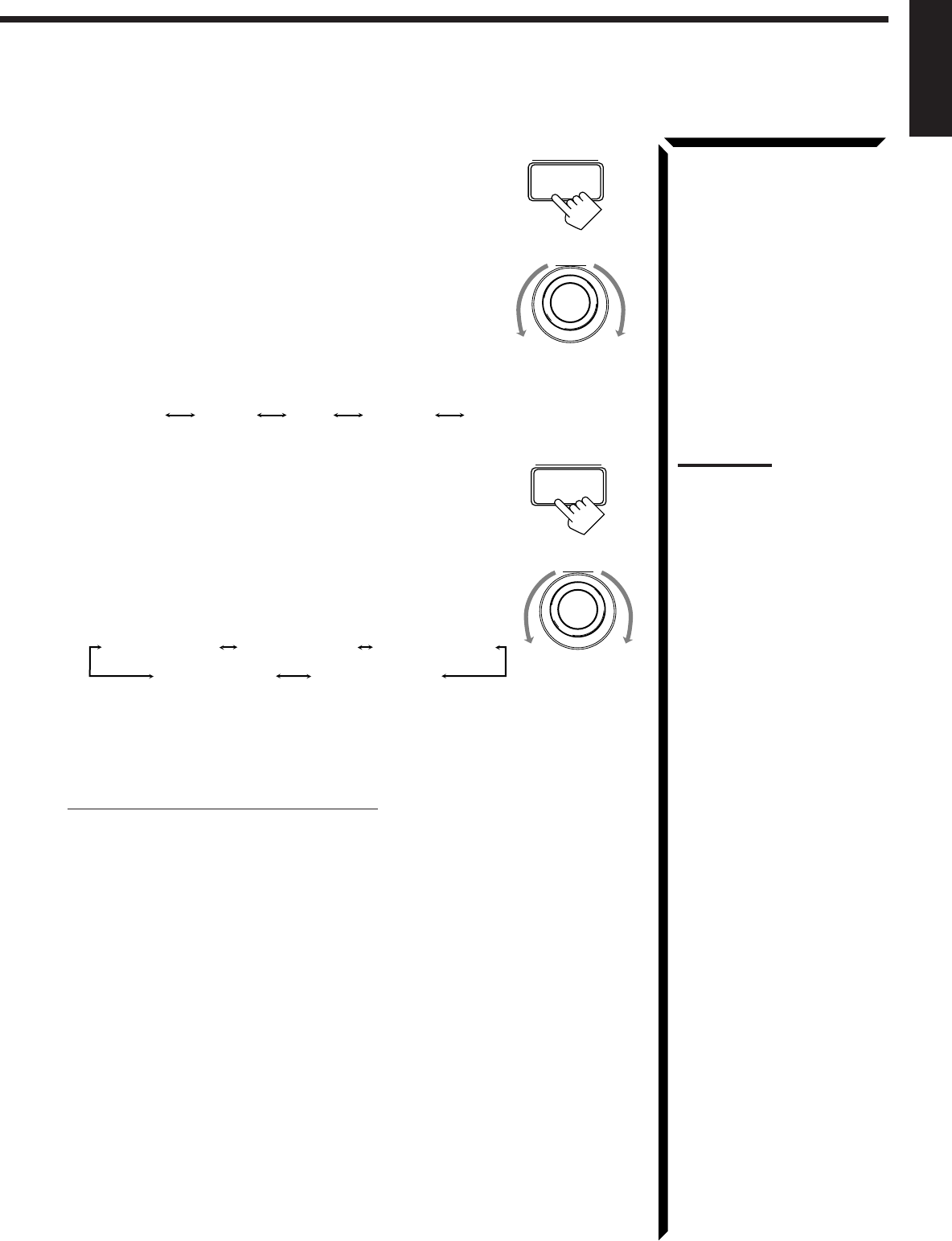
42
English
5. Press BALANCE/SURROUND ADJUST repeatedly
until “CENTER TONE” appears on the display.
The display changes to show the current setting.
6. Turn MULTI JOG to select the center tone level you want,
while the indication of the previous step is still on the
display.
The center tone adjustment affects the mid-frequency
range, which the human voice is mostly made up of.
As you turn it, the display changes to show the
following:
7. Press BALANCE/SURROUND ADJUST repeatedly
until “DSP EFFECT” appears on the display.
The display changes to show the current setting.
8. Turn MULTI JOG to select the effect level, while the
indication of the previous step is still on the display.
As you turn it, the effect level changes as follows:
As the number increases, the surround effect becomes
stronger.
To cancel the Theater Surround mode
Turn MULTI JOG until “DSP OFF” appears in step 3.
The DSP and THEATER indicators goes off.
MULTI JOG
SHARP1 SHARP2FLATSOFT2 SOFT1
BALANCE/SURROUND
ADJUST
BALANCE/SURROUND
ADJUST
DSP EFFECT 1 DSP EFFECT 2
DSP EFFECT 4
DSP EFFECT 3
DSP EFFECT 5
MULTI JOG
Note:
You cannot adjust the effect
level when “REAR SPK” is set
to “NONE” (see page 20).
EN30_42.RX-884P[U]/1.PM5 98.3.4, 2:58 PM42
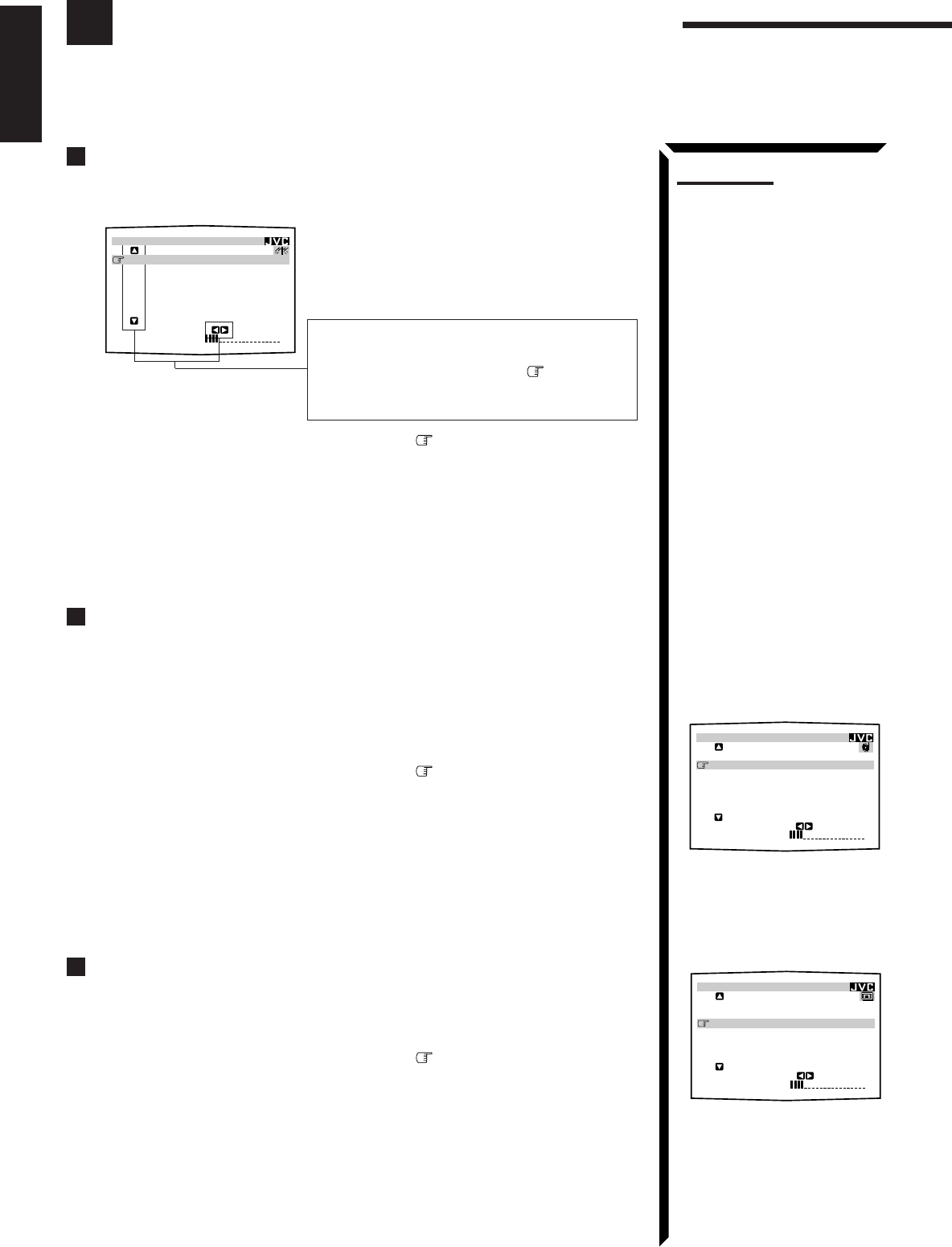
43
English
Using the On-Screen Menus
You can use the menus on the TV screen to control the receiver.
To use this function, you need to connect the TV to the MONITOR OUT jack on the rear panel (see page
10), and set the TV’s input mode to the proper position to which the receiver is connected.
Selecting the Source to Play (Also see page 14)
1. Press any button of ON SCREEN CONTROL % / fi / @ / # once.
The MAIN MENU appears on the TV.
2. Press ON SCREEN CONTROL % / fi to move to “SOURCE.”
3. Press ON SCREEN CONTROL @ / # to select the source.
4. When you finish, press EXIT.
The menu disappears from the TV.
Selecting the Different Sources for Picture and Sound
You can view the pictures played back on a video component while listening to any
source.
1. Press any button of ON SCREEN CONTROL % / fi / @ / # once.
The MAIN MENU appears on the TV.
2. Press ON SCREEN CONTROL % / fi to move to “VISUAL.”
3. Press ON SCREEN CONTROL @ / # to select a different video source.
• When you select “OSD,” see page 51.
4. When you finish, press EXIT.
The menu disappears from the TV.
Using the DSP Modes (Also see pages 31, 34, 36, 39)
1. Press any button of ON SCREEN CONTROL % / fi / @ / # once.
The MAIN MENU appears on the TV.
2. Press ON SCREEN CONTROL % / fi to move to “MODE.”
3. Press ON SCREEN CONTROL @ / # to select the DSP mode you want to use.
4. When you finish, press EXIT.
The menu disappears from the TV.
MAIN MENU
Shows the buttons you can use on the current
menu.
In this case, use % / fi to move up and
down, and @ / # to select, adjust or set the
item.
MAIN MENU
MAIN MENU
MAIN MENU
SOURCE :PHONO
VISUAL :VCR1
MODE :OFF
SOUND CONTROL
TUNER CONTROL
SETTING
VOLUME : 20 :OPERATE
**
**
** **
**
**
MAIN MENU
SOURCE :VCR1
VISUAL :VCR1
MODE :PRO LOGIC
SOUND CONTROL
TUNER CONTROL
SETTING
VOLUME : 20 :OPERATE
**
**
** **
**
**
Notes:
• If your TV is PAL color
system, the TV screen will be
distorted.
• The on-screen display will
disappear if no operation is
done for about one minute.
MAIN MENU
SOURCE :
ch
1
FM
87.50
MHz
VISUAL :VCR1
MODE :OFF
SOUND CONTROL
TUNER CONTROL
SETTING
VOLUME : 20 :OPERATE
**
**
** **
**
**
EN43_57.RX-884P[U]/1.PM5 98.2.20, 2:02 PM43
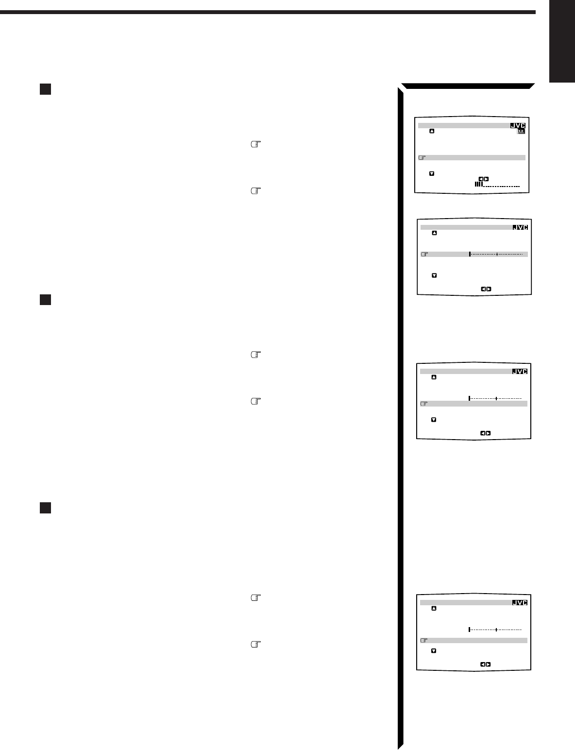
44
English
Adjusting the Front Speaker Output Balance (Also see page 19)
1. Press any button of ON SCREEN CONTROL % / fi / @ / # once.
The MAIN MENU appears on the TV.
2. Press ON SCREEN CONTROL % / fi to move to “SOUND CONTROL,”
then press @ / #.
The SOUND CONTROL menu appears on the TV.
3. Press ON SCREEN CONTROL % / fi to move to “BAL.” (Balance).
4. Press ON SCREEN CONTROL @ / # to adjust the balance.
5. When you finish, press EXIT repeatedly until the menu disappears from the
TV.
Listening at Low Volume (Loudness) (Also see page 19)
1. Press any button of ON SCREEN CONTROL % / fi / @ / # once.
The MAIN MENU appears on the TV.
2. Press ON SCREEN CONTROL % / fi to move to “SOUND CONTROL,”
then press @ / #.
The SOUND CONTROL menu appears on the TV.
3. Press ON SCREEN CONTROL % / fi to move to “LOUDNESS.”
4. Press ON SCREEN CONTROL @ / # to turn the loudness “ON” or “OFF.”
5. When you finish, press EXIT repeatedly until the menu disappears from the
TV.
Attenuating the Input Signal (Also see page 16)
This function is available only for the sources connected using the analog terminals and
takes effect only when the DSP mode is in use.
1. Press any button of ON SCREEN CONTROL % / fi / @ / # once.
The MAIN MENU appears on the TV.
2. Press ON SCREEN CONTROL % / fi to move to “SOUND CONTROL,”
then press @ / #.
The SOUND CONTROL menu appears on the TV.
3. Press ON SCREEN CONTROL % / fi to move to “INPUT ATT.”
4. Press ON SCREEN CONTROL @ / # to turn the function on (“ATT ON”) or
off (“NORMAL”).
5. When you finish, press EXIT repeatedly until the menu disappears from the
TV.
MAIN MENU
SOUND CONTROL menu
SOUND CONTROL menu
MAIN MENU
SOURCE :VCR1
VISUAL :VCR1
MODE :OFF
SOUND CONTROL
TUNER CONTROL
SETTING
VOLUME : 20
:ENTER
**
**
**
**
**
**
SOUND CONTROL
SURROUND LEVEL
SEA
BAL.:R-21
LOUDNESS : OFF
INPUT ATT : NORMAL
SUBWFR LEVEL: 0
dB
NEXT PAGE
:OPERATE
****
****
SOUND CONTROL
SURROUND LEVEL
SEA
BAL.:R-21
LOUDNESS : OFF
INPUT ATT : NORMAL
SUBWFR LEVEL: 0
dB
NEXT PAGE
:OPERATE
****
****
SOUND CONTROL menu
SOUND CONTROL
SURROUND LEVEL
SEA
BAL.:R-21
LOUDNESS : OFF
INPUT ATT : NORMAL
SUBWFR LEVEL: 0
dB
NEXT PAGE
:OPERATE
****
****
EN43_57.RX-884P[U]/1.PM5 98.2.24, 9:38 PM44
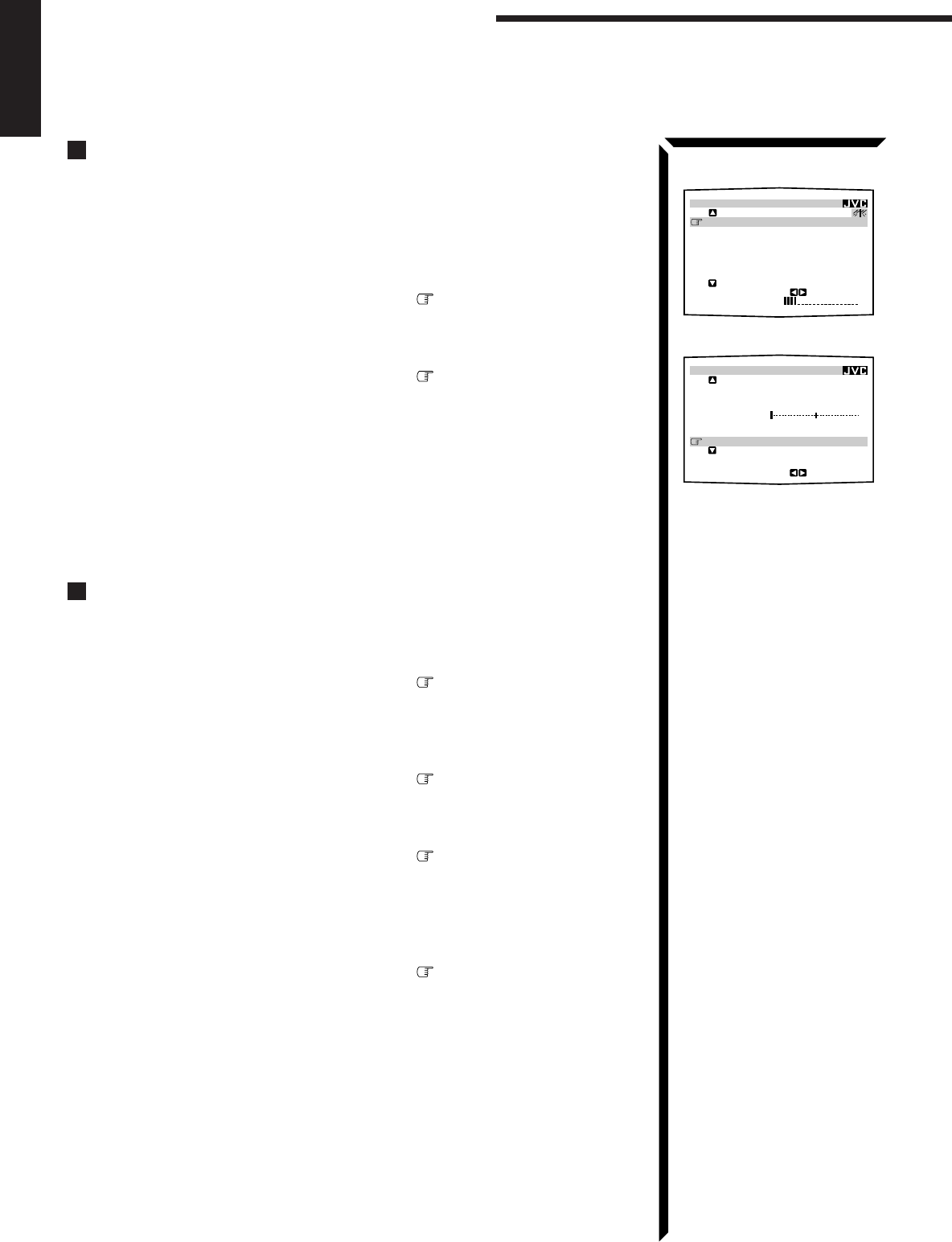
45
English
MAIN MENU
SOUND CONTROL menu
SOUND CONTROL
SURROUND LEVEL
SEA
BAL.:R-21
LOUDNESS : OFF
INPUT ATT : NORMAL
SUBWFR LEVEL: 0
dB
NEXT PAGE
:OPERATE
****
****
Using the On-Screen Menus
Adjusting the Subwoofer Output Level (Also see page 17)
You can adjust the subwoofer output level if you have selected “YES” for the
“SUBWOOFER” (see page 19).
1. Press any button of ON SCREEN CONTROL % / fi / @ / # once.
The MAIN MENU appears on the TV.
2. Press ON SCREEN CONTROL % / fi to move to “SOUND CONTROL,”
then press @ / #.
The SOUND CONTROL menu appears on the TV.
3. Press ON SCREEN CONTROL % / fi to move to “SUBWFR LEVEL”
(Subwoofer Level).
4. Press ON SCREEN CONTROL @ / # to adjust the subwoofer output level.
5. When you finish, press EXIT repeatedly until the menu disappears from the
TV.
Adjusting the DSP Modes (Also see pages 31, 34, 36, and 39)
1. Press any button of ON SCREEN CONTROL % / fi / @ / # once.
The MAIN MENU appears on the TV.
2. Press ON SCREEN CONTROL % / fi to move to “MODE.”
3. Press ON SCREEN CONTROL @ / # to select the DSP mode you want to
adjust.
4. Press ON SCREEN CONTROL % / fi to move to “SOUND CONTROL,”
then press @ / #.
The SOUND CONTROL menu appears.
5. Press ON SCREEN CONTROL % / fi to move to “SURROUND LEVEL,”
then press @ / #.
The SURROUND LEVEL menu appears.
• If you select “HEADPHONE” in step 3, the SURROUND LEVEL menu will not
appear.
6. Press ON SCREEN CONTROL % / fi to move to the item you want to set
or adjust, then press ON SCREEN CONTROL @ / #.
On these adjustment menus, you can do the following:
For 3D-PHONIC modes:
“DSP EFFECT”: Adjust the effect level.
For DAP modes (LIVE CLUB, DANCE CLUB, HALL, PAVILION):
“REAR L LEVEL”: Adjust the left rear speaker output level. *
“REAR R LEVEL”: Adjust the right rear speaker output level. *
“DSP EFFECT”: Select the effect level.
MAIN MENU
SOURCE :
ch
1
FM
87.50
MHz
VISUAL :VCR1
MODE :OFF
SOUND CONTROL
TUNER CONTROL
SETTING
VOLUME : 20
:OPERATE
**
**
**
**
**
**
EN43_57.RX-884P[U]/1.PM5 98.3.4, 3:01 PM45

46
English
For Dolby Surround Pro Logic:
“TEST TONE”: Output a test tone.
“CENTER LEVEL”: Adjust the center speaker output level. **
“REAR L LEVEL”: Adjust the left rear speaker output level. *
“REAR R LEVEL”: Adjust the right rear speaker output level. *
“CENTER TONE”: Select the center tone level. **
For Dolby Digital:
“TEST TONE”: Output a test tone.
“CENTER LEVEL”: Adjust the center speaker output level. **
“REAR L LEVEL”: Adjust the left rear speaker output level. *
“REAR R LEVEL”: Adjust the right rear speaker output level. *
“CENTER TONE”: Select the center tone level. **
For Theater Surround and Digital Theater Surround:
“TEST TONE”: Output a test tone.
“CENTER LEVEL”: Adjust the center speaker output level. **
“REAR L LEVEL”: Adjust the left rear speaker output level. *
“REAR R LEVEL”: Adjust the right rear speaker output level. *
“CENTER TONE”: Select the center tone level. **
“DSP EFFECT”: Select the effect level.*
7. When you finish, press EXIT repeatedly until the menu disappears from the
TV.
Selecting Your Favorite SEA Mode (Also see page 28)
1. Press any button of ON SCREEN CONTROL % / fi / @ / # once.
The MAIN MENU appears on the TV.
2. Press ON SCREEN CONTROL % / fi to move to “SOUND CONTROL,”
then press @ / #.
The SOUND CONTROL menu appears.
3. Press ON SCREEN CONTROL % / fi to move to “SEA,” then press @ / #.
The SEA menu appears.
4. Press ON SCREEN CONTROL % / fi to move to “SEA MODE.”
5. Press ON SCREEN CONTROL @ / # to select the SEA mode you want.
6. When you finish, press EXIT repeatedly until the menu disappears from the
TV.
Example:
SURROUND LEVEL menu
for Theater Surround
SURROUND LEVEL
:OPERATE
TEST TONE : OFF
CENTER LEVEL: 0
dB
REAR L LEVEL: 0
dB
REAR R LEVEL: 0
dB
CENTER TONE : FLAT
DSP EFFECT : 3
SEA menu
SOUND CONTROL menu
MAIN MENU
MAIN MENU
SOURCE :VCR1
VISUAL :VCR1
MODE :OFF
SOUND CONTROL
TUNER CONTROL
SETTING
VOLUME : 20
:ENTER
**
**
**
**
**
**
SEA
SEA MODE :ROCK
SEA ADJUST
:OPERATE
** **
100 10kHz1k
SOUND CONTROL
SURROUND LEVEL
SEA
BAL.:CNTR
LOUDNESS : OFF
INPUT ATT : NORMAL
SUBWFR LEVEL: 0
dB
NEXT PAGE
:ENTER
****
****
Notes:
* Not displayed when “REAR
SPK” is set to “NONE” (see
page 20).
** Not displayed when
“CENTER SPK” is set to
“NONE” (see page 20).
EN43_57.RX-884P[U]/1.PM5 98.2.24, 9:38 PM46

47
English
Using the On-Screen Menus
MAIN MENU
SOUND CONTROL menu
SEA menu
SEA ADJUST menu
MAIN MENU
SOURCE :VCR1
VISUAL :VCR1
MODE :OFF
SOUND CONTROL
TUNER CONTROL
SETTING
VOLUME : 20
:ENTER
**
**
**
**
**
**
SOUND CONTROL
SURROUND LEVEL
SEA
BAL.:CNTR
LOUDNESS : OFF
INPUT ATT : NORMAL
SUBWFR LEVEL: 0
dB
NEXT PAGE
:ENTER
****
****
SEA
SEA MODE :ROCK
SEA ADJUST
:OPERATE
** **
100 10kHz1k
SETTING 1
SUBWOOFER : NO
FRONT SPK : LARGE
CENTER SPK : SMALL
REAR SPK : LARGE
CNTR DELAY : 3msec
REAR DELAY : 5msec
NEXT PAGE
:ENTER
****
SETTING 1 menu
SETTING 2
CROSSOVER :100
Hz
LFE ATT. : 0
dB
COMP. : OFF
DIGITAL 1 : DBS
DIGIATL 2 : CD
DIGITAL 3 : MD
PREVIOUS PAGE
:ENTER
****
SETTING 2 menu
Creating Your Own SEA Mode (Also see page 29)
1. Press any button of ON SCREEN CONTROL % / fi / @ / # once.
The MAIN MENU appears on the TV.
2. Press ON SCREEN CONTROL % / fi to move to “SOUND CONTROL,”
then press @ / #.
The SOUND CONTROL menu appears.
3. Press ON SCREEN CONTROL % / fi to move to “SEA,” then press @ / #.
The SEA menu appears.
4. Press ON SCREEN CONTROL % / fi to move to “SEA ADJUST,” then
press @ / #.
The SEA ADJUST menu appears.
5. Press ON SCREEN CONTROL % / fi / @ / # to adjust the SEA mode as you
want.
@ / # : Select the frequency ranges.
% / fi : Adjust the frequency levels.
6. Press SET to store the setting into the SEA USERMODE.
• If you press EXIT, without pressing SET in this step, you can return to the SEA
menu. (The adjustment you have made is active but not stored.)
7. When you finish, press EXIT repeatedly until the menu disappears from the
TV.
Basic Settings
1. Press any button of ON SCREEN CONTROL % / fi / @ / # once.
The MAIN MENU appears on the TV.
2. Press ON SCREEN CONTROL % / fi to move to “SETTING,” then press
@ / #.
The SETTING 1 or SETTING 2 menu appears.
3. Press ON SCREEN CONTROL % / fi to the setting item you want to adjust.
• To go to the SETTING 2 menu, move to “NEXT PAGE,” then press @ / #.
• To go back to the SETTING 1 menu, move to “PREVIOUS PAGE,” then
press @ / #.
On the SETTING 1 and 2 menus, you can do the following:
“SUBWOOFER”: Set the subwoofer information (See page 19).
“FRONT SPK”: Set the front speaker information (See page 20).
“CENTER SPK”: Set the center speaker information (See page 20).
“REAR SPK”: Set the rear speaker information (See page 20).
“CNTR DELAY”: Adjust the delay time of the center speaker output (See page 21).
“REAR DELAY”: Adjust the delay time of the rear speaker output (See page 21).
“CROSSOVER”: Set the crossover frequency (See page 21).
“LFE ATT.”: Set the low frequency effect attenuator level (See page 22).
“COMP.”: Set the dynamic range compression (See page 22).
“DIGITAL 1/2/3”: Set the digital input terminal (See page 20).
SEA ADJUST
SEA USERMODE
SET
:MEMORY
100 10kHz1k
EN43_57.RX-884P[U]/1.PM5 98.3.3, 2:52 PM47

48
English
4. Press ON SCREEN CONTROL @ / # to set (or adjust) the setting item selected
in step 3.
5. When you finish, press EXIT repeatedly until the menu disappears from the
TV.
Operating the Tuner
1. Press any button of ON SCREEN CONTROL % / fi / @ / # once.
The MAIN MENU appears on the TV.
2. Press ON SCREEN CONTROL % / fi to move to “TUNER CONTROL,”
then press @ / #.
The TUNER CONTROL menu appears.
3. Press ON SCREEN CONTROL % / fi to move to the item you want to set
or adjust, then press ON SCREEN CONTROL @ / #.
On the TUNER CONTROL menu, you can do the following:
“PRESET CH”: Select a preset channel station. (See page 25)
“BAND”: Select the band. (See page 24)
“FREQUENCY”: Tune in a station manually. (See page 24)
“FM MODE”: Select the FM reception mode. (See page 26) *
“PRESET MEMORY”: See “Storing the Preset Stations” below.
4. When you finish, press EXIT repeatedly until the menu disappears from the
TV.
Storing the Preset Stations (Also see page 24)
1. Press any button of ON SCREEN CONTROL % / fi / @ / # once.
The MAIN MENU appears on the TV.
2. Press ON SCREEN CONTROL % / fi to move to “TUNER CONTROL,”
then press @ / #.
The TUNER CONTROL menu appears.
3. Tune into a station on the TUNER CONTROL menu, referring to “Operating
the Tuner” above.
4. Press ON SCREEN CONTROL % / fi to move to “PRESET MEMORY,”
then press @ / #.
The PRESET MEMORY menu appears.
5. Press ON SCREEN CONTROL % / fi to move to “PRESET CH.”
6. Press ON SCREEN CONTROL @ / # to select a preset station number you
want.
7. Press SET to store the setting.
8. When you finish, press EXIT repeatedly until the menu disappears from the
TV.
MAIN MENU
TUNER CONTROL menu
PRESET MEMORY menu
Note:
* Not displayed when an AM
station is selected.
PRESET MEMORY
FM 87.50
MHz
AUTO
PRESET CH : CH 1
PRESET NAME: WABC
:OPERATE
:MEMORY
SET
TUNER CONTROL
PRESET CH : 1
BAND :FM
FREQUENCY : 87.50
MHz
FM MODE :AUTO
PRESET MEMORY
:OPERATE
****
MAIN MENU
SOURCE :
ch
1
FM
87.50
MHz
VISUAL :VCR1
MODE :OFF
SOUND CONTROL
TUNER CONTROL
SETTING
VOLUME : 20 :ENTER
**
**
** **
**
**
EN43_57.RX-884P[U]/1.PM5 98.2.20, 2:03 PM48
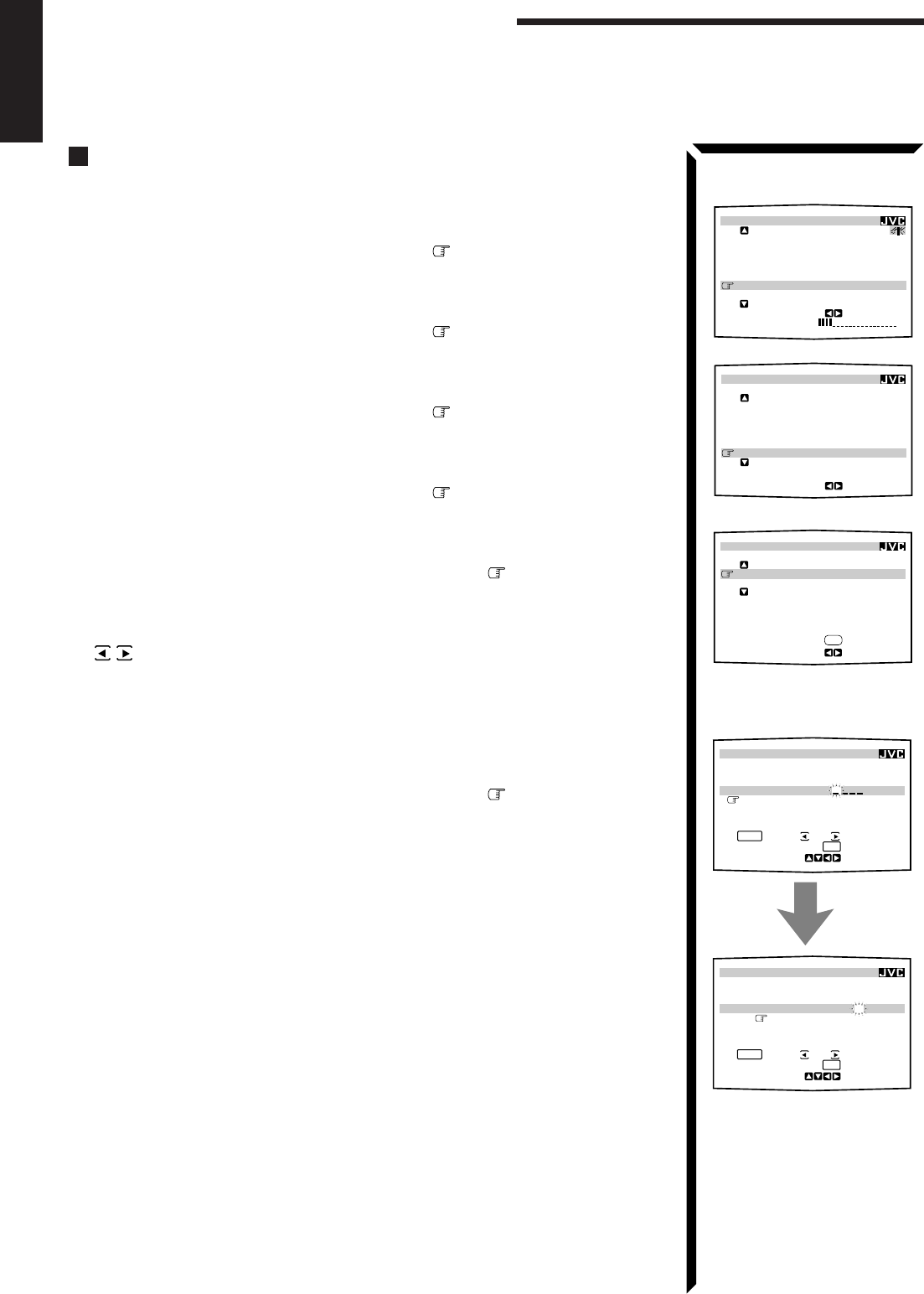
49
English
Using the On-Screen Menus
Assigning Names to the Preset Stations (Also see page 26)
1. Press any button of ON SCREEN CONTROL % / fi / @ / # once.
The MAIN MENU appears on the TV.
2. Press ON SCREEN CONTROL % / fi to move to “TUNER CONTROL,”
then press @ / #.
The TUNER CONTROL menu appears.
3. Press ON SCREEN CONTROL % / fi to move to “PRESET CH.”
4. Press ON SCREEN CONTROL @ / # to select a preset station.
5. Press ON SCREEN CONTROL % / fi to move to “PRESET MEMORY,”
then press @ / #.
The PRESET MEMORY menu appears.
6. Press ON SCREEN CONTROL % / fi to move to “PRESET NAME,” then
press SET.
The character entry screen appears.
7. Press ON SCREEN CONTROL % / fi / @ / # to move in front of a
character you want.
You can also select the following:
SPACE: To enter space CANCEL: To erase the character
: To go back to the previous character position or go to the next character
position
8. Press SET to enter the selected character.
9. Repeat steps 7 and 8 to enter up to four characters.
10. Press ON SCREEN CONTROL % / fi / @ / # to move to “PRESET
NAME,” then press SET to store the setting.
The TUNER CONTROL menu appears again.
11. When you finish, press EXIT repeatedly until the menu disappears from the
TV.
MAIN MENU
PRESET MEMORY menu:
Character entry screen
PRESET MEMORY
SET
:MEMORY
:OPERATE
FM 107.90
MHz
AUTO
PRESET CH : CH39
PRESET NAME:
A B C D E F G H I J K
L M N O P Q R S T U V
W X Y Z
1 2 3 4 5 6 7 8 9 0
SPACE
CANCEL
PRESET MEMORY
SET
:MEMORY
:OPERATE
FM 107.90
MHz
AUTO
PRESET CH : CH39
PRESET NAME: WABC
A B C D E F G H I J K
L M N O P Q R S T U V
W X Y Z
1 2 3 4 5 6 7 8 9 0
SPACE
CANCEL
TUNER CONTROL menu
PRESET MEMORY menu
PRESET MEMORY
FM 87.50
MHz
AUTO
PRESET CH : CH39
PRESET NAME: WABC
:OPERATE
:MEMORY
SET
MAIN MENU
SOURCE :
ch
1
FM
87.50
MHz
VISUAL :VCR1
MODE :OFF
SOUND CONTROL
TUNER CONTROL
SETTING
VOLUME : 20
:ENTER
**
**
**
**
**
**
TUNER CONTROL
PRESET CH :39
BAND :FM
FREQUENCY : 87.50
MHz
FM MODE :AUTO
PRESET MEMORY
:ENTER
****
EN43_57.RX-884P[U]/1.PM5 98.3.17, 5:43 PM49

50
English
COMPU LINK Remote Control System
The COMPU LINK remote control system allows you to operate JVC audio components through the remote
sensor on the receiver.
To use this remote control system, you need to connect JVC audio components through
the COMPU LINK-3 (SYNCHRO) jacks (see below) in addition to the connections
using cables with RCA pin plugs (see page 9) (and a digital cable if you want — see
page 12).
• Make sure that the AC power cords of these components are unplugged before
connection. Plug the AC power cords only after all connections are complete.
This remote control system allows you to use four functions listed below.
Remote Control through the Remote Sensor on the Receiver
You can control the connected audio components through the remote sensor on the
receiver using this remote control. Aim the remote control directly at the remote sensor
on the receiver. For details, see pages 58 and 59.
Automatic Source Selection
When you press the play (33
33
3) button on a connected component or on its own remote
control, the receiver automatically turns on and changes the source to the component.
On the other hand, if you select a new source on the receiver or the remote control, the
selected component begins playing immediately.
In both cases, the previously selected source continues playing without sound for a few
seconds.
Automatic Power On/Off (Standby): only possible with the COMPU
LINK-3 connection
Both the CD player and cassette deck (or MD recorder) turn on and off (standby) along
with the receiver.
When you turn on the receiver, the CD player or cassette deck (or MD recorder) will
turn on automatically, depending on which component has been previously selected.
When you turn off the receiver, both the CD player and cassette deck (or MD recorder)
will turn off (standby).
Synchronized Recording
Synchronized recording means the cassette deck (or MD recorder) starts recording as
soon as a CD or a record begins playing.
To use synchronized recording, follow these steps:
1. Put a tape in the cassette deck (or an MD in the MD recorder), and a disc in the
CD player (or a record on the turntable).
2. Press the record (¶¶
¶¶
¶) button and the pause (88
88
8) button on the cassette deck (or
MD recorder) at the same time.
This puts the cassette deck (or MD recorder) into recording pause.
If you do not press the record (¶) button and pause (8) button at the same time, the
synchronized recording feature will not operate.
3. Press the play (33
33
3) button on the CD player or on the turntable.
The source changes on the receiver, and as soon as play starts, the cassette deck (or
MD recorder) starts recording. When the play ends, the cassette deck (or MD
recorder) enters recording pause, and stops about 4 seconds later.
Notes:
• If your audio component has
two COMPU LINK-3
(SYNCHRO) jacks, you can
use either one. If it has only
one COMPU LINK-3
(SYNCHRO) jack, connect it
so that it is the last item in the
series of components. (For
example, the turntable or CD
player in the diagram to the
left.)
• To operate the cassette deck
or MD recorder using the
COMPU LINK remote control
system, set the source name
correctly. (See page 18.)
• Refer also to the manuals
supplied with your audio
components.
Notes:
• During synchronized
recording, the selected source
cannot be changed.
• If your CD player is playing in
program mode, a 4-second
blank is recorded between
tracks so that the music scan
feature of your cassette deck
can be used on the recorded
tape.
• If the power of any component
is shut off during synchronized
recording, the COMPU LINK
remote control system may
not operate properly. In this
case, you must start again
from the beginning.
CD player
Turntable
COMPU LINK – 3
(SYNCHRO)
Cassette deck
or
MD recorder
EN43_57.RX-884P[U]/1.PM5 98.3.13, 11:32 AM50

51
English
TEXT COMPU LINK Remote Control System
The TEXT COMPU LINK remote control system has been newly developed to deal with the disc information
recorded in the CD Text* and MDs. Using these information in the discs, you can operate the CD player or
MD recorder equipped with the TEXT COMPU LINK remote control system through the receiver.
CONNECTIONS:
To use this remote control system, you need to connect the CD player and/or MD
recorder you want to operate, following the procedures below.
1. If you have already plugged your CD player, MD recorder, and this receiver
into the AC outlets, unplug their AC power cords first.
2. Connect your CD player, MD recorder, and this receiver as follows, through the
COMPU LINK-3 (SYNCHRO) jacks and TEXT COMPU LINK jacks.
1) COMPU LINK-3 (SYNCHRO) jacks: Use the cables with the monaural mini-
plugs (not supplied with this receiver)
2) TEXT COMPU LINK jacks: Use the cables with the stereo mini-plugs (not
supplied with this receiver)
IMPORTANT:
Set the Master/Slave Selector on the rear to “1(MASTER UNIT).”
• “2(SLAVE UNIT)” is just for the serviceman’s use. The TEXT
COMPU LINK remote control system does not function with
the selector set to “2(SLAVE UNIT).”
3. Connect your CD player, MD recorder and this receiver, using the cables with
RCA pin plugs (see page 9) (and a digital cable if you want — see page 12).
4. Plug the AC power cords of these components above into the AC outlets.
5. When turning on these components for the first time, turn on the connected
components first, then turn on this receiver.
FUNCTIONS:
This remote control system allows you to use the functions listed below.
Displaying the Disc Information on the TV screen
Disc information such as its performer and disc title (and track titles only when a CD
Text is selected) is shown on the TV screen.
Disc Search: Only for CD Player
This remote control system can allow you to search discs by the performer, disc title,
and music genre.
With this disc search, you can easily find the disc you want to play.
Additional Functions:
• If your CD player has the User File function, you can select a disc from the groups.
* A “user file” is a group of the discs you make as you like on the CD player.
• If your CD player has the disc memory function, you can input the performer, disc
title, and music genre about these normal audio CDs on the TV screen.
*What is a CD Text?
In a CD Text, some information
about the disc (its disc title,
performer, composer, arranger,
etc.) is recorded.
Notes:
• If your audio component has
two COMPU LINK-3
(SYNCHRO) jacks, you can
use either one. If it has only
one COMPU LINK-3
(SYNCHRO) jack, connect it
so that it is the last item in the
series of components. (For
example, the CD player in the
diagram to the left.)
• If your audio component has
two TEXT COMPU LINK
jacks, you can use either one.
If it has only one TEXT
COMPU LINK jack, connect it
so that it is the last item in the
series of components. (For
example, the CD player in the
diagram to the left.)
• Refer also to the manuals
supplied with your CD player
or MD recorder.
COMPU LINK – 3
(SYNCHRO)
CD player MD recorder
TEXT
COMPU LINK
1(MASTER UNIT)
2(SLAVE UNIT)
CD player MD recorder
Note:
If you turn on the receiver before
turning on the other components
after connecting components,
the TEXT COMPU LINK remote
control system does not work
correctly.
If this happens:
1.Turn off the all components
including this receiver.
2.Turn on the connected
components.
3.Turn on this receiver.
EN43_57.RX-884P[U]/1.PM5 98.3.13, 11:32 AM51

52
English
OPERATIONS
To use this remote control system, you need to connect the TV to the MONITOR OUT
jack on the rear panel (see page 10), and set the TV’s input mode to the proper position
to which the receiver is connected. Make sure you have connected the CD
player or MD recorder equipped with the TEXT COMPU LINK remote
control system. If not, you cannot use the following functions.
Showing the Disc Information on the TV Screen
1. Press any button of ON SCREEN CONTROL % / fi / @ / # once.
The MAIN MENU appears on the TV.
2. Press ON SCREEN CONTROL % / fi to move to “SOURCE.”
3. Press ON SCREEN CONTROL @ / # to select “CD” or “MD.”
4. Press ON SCREEN CONTROL % / fi to move to “VISUAL.”
5. Press ON SCREEN CONTROL @ / # to select “OSD,” then press EXIT.
The Disc Information screen appears on the TV.
1Source name: CD or MD
2Select or , then press SET to change the disc.
3Track numbers and track titles.
• The current playing (selected) track is indicated in yellow.
• When you move to a track number, you can change the track information by
pressing @ / #. Each time you press the button, track information alternates
between its track title and its performer. (You can also start playing the track by
pressing SET.)
4Select this (move in front), then press SET to go to the DISC SEARCH screen
(see page 53).
5Select this (move in front), then press SET to go to the USER FILE screen (see
page 55).
6Select this (move in front), then press SET to go to the TITLE INPUT screen (see
page 56).
7Disc information such as the disc title, performer, and music genre.
When this is selected ( in front) , you can change the disc information by pressing
@ / #. Each time you press the button, disc information (see the note) changes.
8Select or , then press SET to change the track.
9Usable buttons and their functions for the current selection.
Indication here will be changed what is currently selected ( in front) on the
screen.
6. When you finish, press EXIT repeatedly until the MAIN MENU appears on
the TV.
To exit from the MAIN MENU:
1) Press ON SCREEN CONTROL % / fi to move to “VISUAL.”
2) Press ON SCREEN CONTROL @ / # to select any one other than “OSD,” then
press EXIT.
Notes:
• The on-screen display will not
appear about one minute after
the power is turned on.
• The on-screen display will
disappear in the following
case:
– if no operation is done for
about 10 minutes.
– if you do any operation
other than explained in this
section.
• To control the MD recorder
using the TEXT COMPU LINK
remote control system, you
have to change the source
name shown on the display
from “TAPE” to “MD.” (See
page 18.)
• The number of characters to
show the disc information
such as the disc title or track
title is limited to 32. So if the
disc title, for example, is
longer than 32 characters,
only the first 32 characters are
shown.
• Some special characters such
as accented letters cannot be
displayed correctly.
Note on
7
The following information will
appear on the display:
• Disc title
• Performer
• Genre
• Song writer
• Composer
• Arranger
• Message
Only recorded information will
be shown. If there is no data,
“NO DATA” will appear.
Note on
9
For example, the SET button will
be used to start play (PLAY), to
go to the next screen (ENTER),
and to determine the selection
(ENTER).
EN43_57.RX-884P[U]/1.PM5 98.2.20, 2:03 PM52

53
English
Searching a Disc (Only for the CD player)
Search a disc by its performer:
1. Display the disc information screen by following the procedure on page 52.
2. Press ON SCREEN CONTROL % / fi to move to “SEARCH,” then
press SET.
The DISC SEARCH screen appears on the TV.
3. Press ON SCREEN CONTROL % / fi to move to “PERFORMER”, then
press SET.
The PERFORMER SEARCH screen appears.
4. Press ON SCREEN CONTROL % / fi / @ / # to move in front of the
first character of the performer you want to search, then press SET.
To correct the incorrect entry, press ON SCREEN CONTROL % / fi to
move in front of the correct character, then press SET.
To erase the incorrect entry, press ON SCREEN CONTROL % / fi to move to
CANCEL, then press SET.
5. Press SET again.
Disc search starts, then the SEARCH RESULT screen, showing the performers,
appears.
6. On the SEARCH RESULT screen, you can do the following:
•Changing the indication of the disc information: Press ON SCREEN
CONTROL % / fi to move to a searched disc, then press @ / #. Each time you
press @ / #, the disc information alternates between its performer and its disc
title.
•Going to the Disc Information screen (see page 52): Press ON SCREEN
CONTROL % / fi to move to a searched disc, then press SET.
•Showing unseen disc information (if more than 5 discs are listed as a result of
the search): Press ON SCREEN CONTROL % / fi to move to (or ),
then press SET.
•Going back to the PERFORMER SEARCH screen: Press EXIT.
Search a disc by its disc title:
1. Display the disc information screen by following the procedure on page 52.
2. Press ON SCREEN CONTROL % / fi to move to “SEARCH,” then
press SET.
The DISC SEARCH screen appears on the TV.
3. Press ON SCREEN CONTROL % / fi to move “DISC TITLE”, then
press SET.
The DISC TITLE SEARCH screen appears.
4. Press ON SCREEN CONTROL % / fi / @ / # to move in front of the
first character of the disc title you want to search, then press SET.
To correct the incorrect entry, press ON SCREEN CONTROL % / fi move in
front of the correct character, then press SET.
To erase the incorrect entry, press ON SCREEN CONTROL % / fi move to
CANCEL, then press SET.
TEXT COMPU LINK Remote Control System
DISC SEARCH screen
PERFORMER SEARCH
screen
SEARCH RESULT screen
DISC SEARCH screen
Note
Symbols such as @, # or $
cannot be available for search.
DISC TITLE SEARCH screen
EN43_57.RX-884P[U]/1.PM5 98.3.18, 11:34 AM53

54
English
5. Press SET again.
Disc search starts, then the SEARCH RESULT screen, showing the disc titles,
appears.
6. On the SEARCH RESULT screen, you can do the following:
•Changing the indication of the disc information: Press ON SCREEN
CONTROL % / fi to move to a searched disc, then press @ / #. Each time you
press @ / #, the disc information alternates between its disc title and its
performer.
•Going to the Disc Information screen (see page 52): Press ON SCREEN
CONTROL % / fi to move to a searched disc, then press SET.
•Showing unseen disc information (if more than 5 discs are listed as a result of
the search): Press ON SCREEN CONTROL % / fi to move to (or ),
then press SET.
•Going back to the DISC TITLE SEARCH screen: Press EXIT.
Search a disc by its genre:
1. Display the disc information screen by following the procedure on page 52.
2. Press ON SCREEN CONTROL % / fi to move to “SEARCH,” then
press SET.
The DISC SEARCH screen appears on the TV.
3. Press ON SCREEN CONTROL % / fi to move to “GENRE”, then press
SET.
The GENRE SEARCH screen appears.
4. Press ON SCREEN CONTROL % / fi to move to the genre you want to
search, then press SET.
To show the unseen genres, press ON SCREEN CONTROL % / fi until they appear.
Disc search starts, then the SEARCH RESULT screen, showing the disc titles,
appears.
5. On the SEARCH RESULT screen, you can do the following:
•Changing the indication of the disc information: Press ON SCREEN
CONTROL % / fi to move to a searched disc, then press @ / #. Each time you
press @ / #, the disc information alternates between its disc title and its
performer.
•Going to the Disc Information screen (see page 52): Press ON SCREEN
CONTROL % / fi to move to a searched disc, then press SET.
•Showing unseen disc information (if more than 5 discs are listed as a result of
the search): Press ON SCREEN CONTROL % / fi to move to (or ),
then press SET.
•Going back to the GENRE SEARCH screen: Press EXIT.
GENRE SEARCH screen
SEARCH RESULT screen
SEARCH RESULT screen
Note
Symbols such as @, # or $
cannot be available for search.
EN43_57.RX-884P[U]/1.PM5 98.3.18, 11:35 AM54
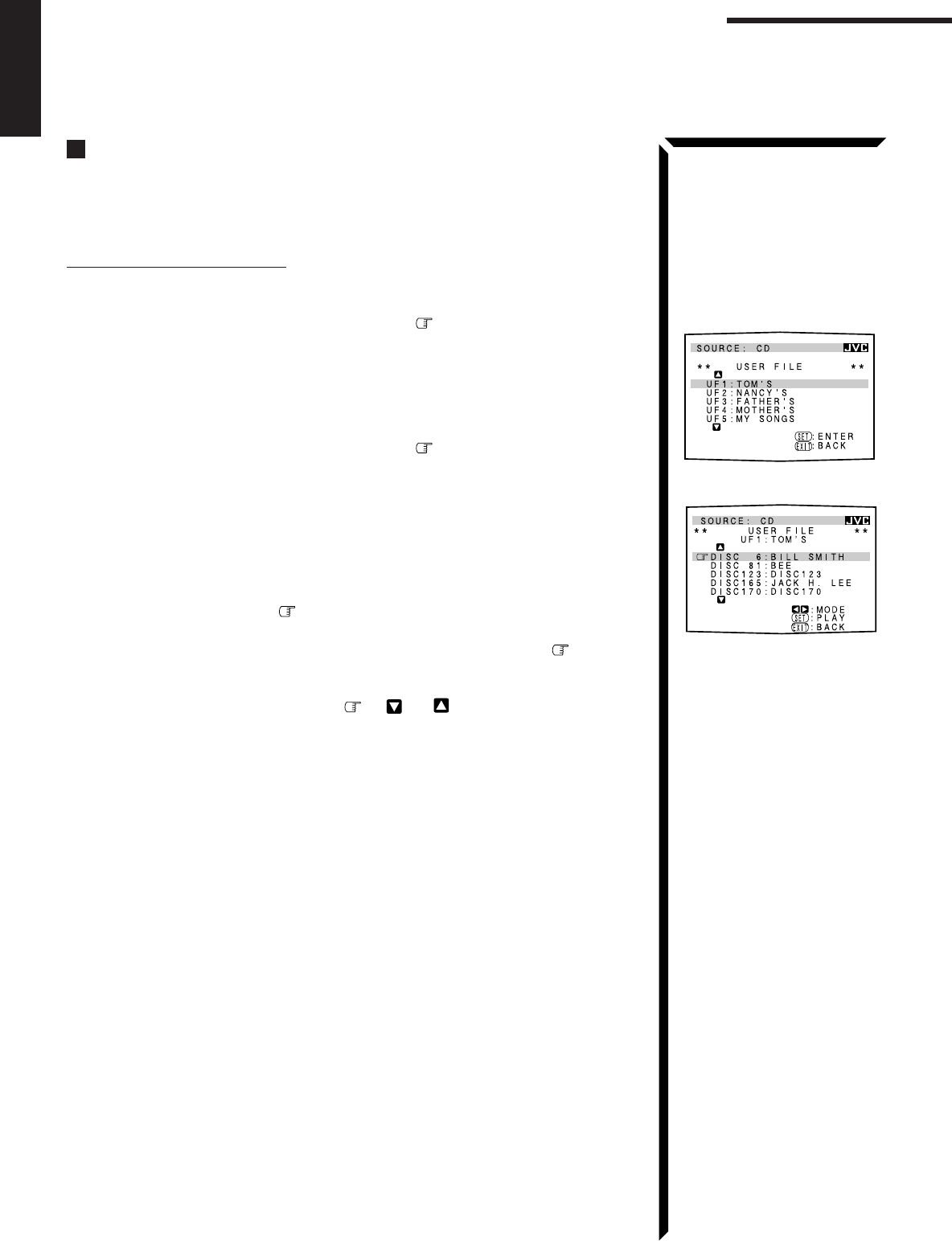
55
English
TEXT COMPU LINK Remote Control System
Using the User File (Only for the CD Player with the User
File Function)
You can use the User File function through this receiver.
For the User File function, refer to the manual supplied with your CD player.
Using your own User Files:
1. Display the disc information screen by following the procedure on page 52.
2. Press ON SCREEN CONTROL % / fi to move to “USER FILE,” then
press SET.
The USER FILE screen appears on the TV.
To show the unseen user files, press ON SCREEN CONTROL % / fi until they
appear.
3. Press ON SCREEN CONTROL % / fi to move to the User File you want,
then press SET.
The selected User File screen appears on the TV.
The disc information shown will be the disc title. (If no disc title information is
recorded for the discs, only the disc numbers will be shown.)
4. On this selected User File screen, you can do the following:
•Changing the indication of the disc information: Press ON SCREEN
CONTROL % / fi to move to a disc, then press @ / #. Each time you press @
/ #, the disc information alternates between its disc title and its performer.
•Starting a disc play: Press ON SCREEN CONTROL % / fi to move to a disc,
then press SET.
•Showing unseen disc information (if more than 5 discs are listed): Press ON
SCREEN CONTROL % / fi to move to (or ) and press SET.
•Going back to the USER FILE screen: Press EXIT.
USER FILE screen
User File 1 screen
EN43_57.RX-884P[U]/1.PM5 98.2.23, 11:33 AM55
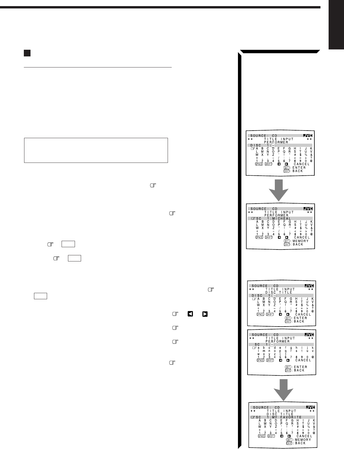
56
English
Entering the Disc Information
For the CD Player with the disc memory function:
You can use the disc memory function through this receiver.
The disc information (its performer, disc title, and its music genre) of normal audio CDs
will be stored into the memory built in the CD player.
For the disc memory function, refer to the manual supplied with your CD player.
• The performer, disc title, and music genre information are usually recorded in a CD
Text. However, if a CD Text has no genre information recorded in the disc itself, you
can input its music genre by yourself.
Note: You can enter the TITLE INPUT screens for a CD Text and input its titles.
However, you cannot store the titles you have input for a CD Text.
Example: Entering the following information for Disc 1
Performer: “MICHEAL”
Disc title: “MY FAVORITE”
1. Display the disc information screen by following the procedure on page 52.
2. Press ON SCREEN CONTROL % / fi to move to “TITLE INPUT,” then
press SET.
The TITLE INPUT: PERFORMER screen appears on the TV.
3. Press ON SCREEN CONTROL % / fi / @ / # to move in front of a
character you want, then press SET to enter the character.
•If the current CD is a CD Text, go to step 5 without entering the performer.
To use the lower case letters, press ON SCREEN CONTROL % / fi / @ / # to
move to
SHIFT
, then press SET.
To use the upper case letters again, press ON SCREEN CONTROL % / fi / @ / #
to move to
SHIFT
, then press SET.
4. Repeat step 3 until you finish putting a name (up to 32 characters) to this
User File.
To insert a space, press ON SCREEN CONTROL % / fi / @ / # to move to
SPACE
, then press SET.
To correct an incorrect character:
1) Press ON SCREEN CONTROL % / fi / @ / # to move to or , then
press SET until the incorrect character is selected.
2) Press ON SCREEN CONTROL % / fi / @ / # to move to CANCEL, then
press SET to erase the character.
3) Press ON SCREEN CONTROL % / fi / @ / # to move in front of an correct
character, then press SET to enter a correct character.
5. Press ON SCREEN CONTROL % / fi / @ / # to move to “DISC1:
MICHEAL (in this example),” then press SET.
The TITLE INPUT: DISC TITLE screen appears.
6. Enter the disc title, referring to steps 3 and 4.
•If the current CD is a CD Text, go to the next step without entering the disc
title.
TITLE INPUT: PERFORMER
screen
TITLE INPUT: DISC TITLE
screen
Continued to the next page.
EN43_57.RX-884P[U]/1.PM5 98.2.23, 11:33 AM56
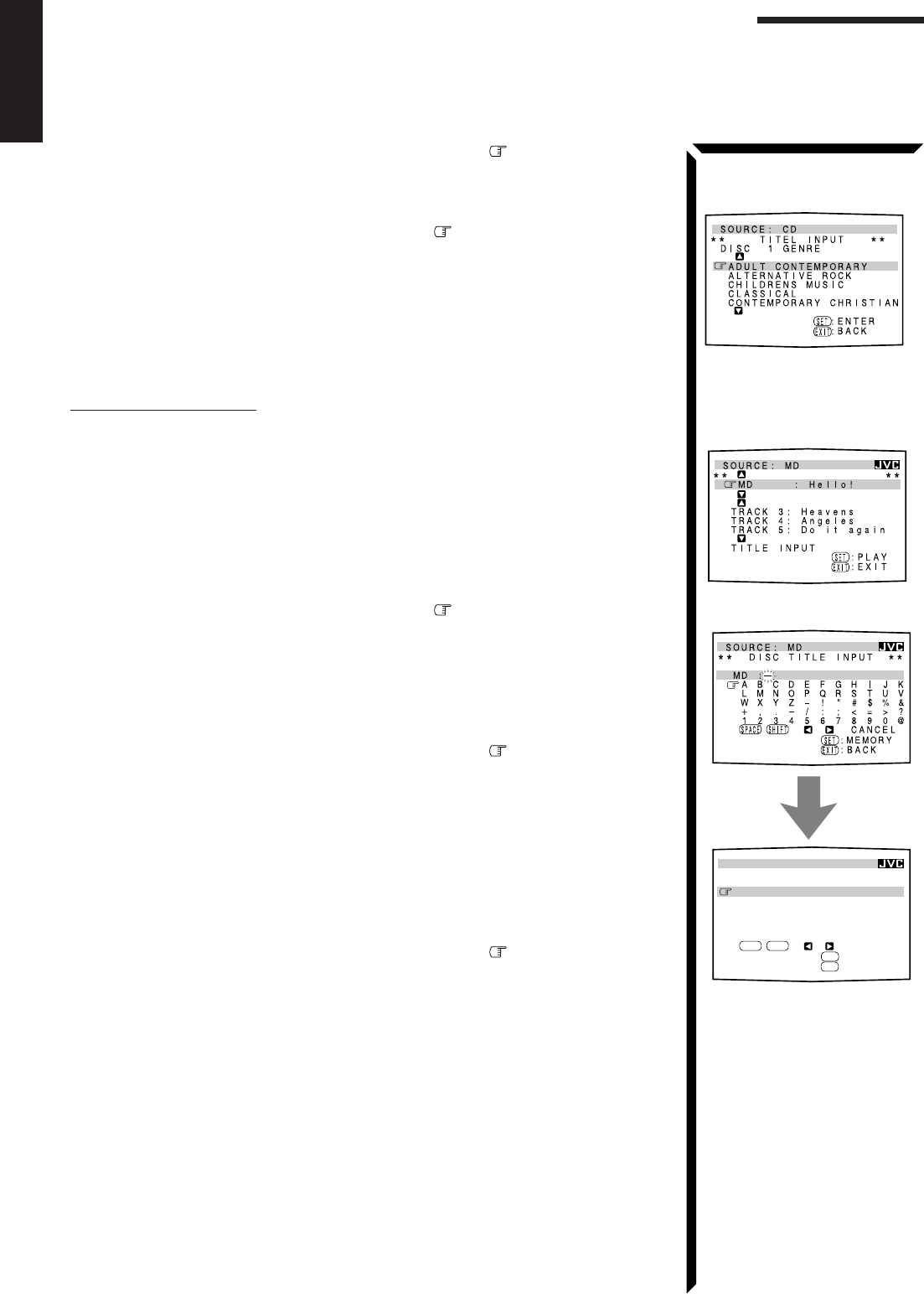
57
English
7. Press ON SCREEN CONTROL % / fi / @ / # to move to “DISC1: MY
FAVORITE (in this example),” then press SET.
The TITLE INPUT: DISC 1 GENRE screen appears.
8. Press ON SCREEN CONTROL % / fi to move to the genre you want,
then press SET.
The Disc Information screen appears again.
To show the unseen genres, press ON SCREEN CONTROL % / fi until they appear.
For the MD recorder:
You can write the disc information (disc title and song titles) into the disc. You can only
write the song title for the song currently selected.
• If you have the CD-MD combination deck, you can also enter the disc information
(its performer, disc title, and its music genre) of normal audio CDs into the memory
built in the CD-MD combination deck. (To do this, follow the procedure on page
56.)
1. Display the disc information screen by following the procedure on page 52.
2. Press ON SCREEN CONTROL % / fi to move to “TITLE INPUT,” then
press SET.
The DISC TITLE INPUT screen appears on the TV.
3. Enter the disc title, referring to steps 3 and 4 on page 56.
• You can enter up to 32 character for the disc title.
4. Press ON SCREEN CONTROL % / fi / @ / # to move to the disc title
you have just entered, then press SET.
The disc title is stored into the memory, and the SONG TITLE INPUT screen for the
currently selected song appears.
• You can enter a song title for the song currently selected (indicated in yellow on the
TV screen).
5. Enter the song title, referring to steps 3 and 4 on page 56.
• You can enter up to 32 character for the song title.
6. Press ON SCREEN CONTROL % / fi / @ / # to move to the song title
you have just entered, then press SET.
The song title is stored into the memory, and the Disc Information screen appears
again.
TEXT COMPU LINK Remote Control System
Disc Information screen
DISC TITLE INPUT screen
TITLE INPUT: DISC 1 GENRE
screen
SOURCE: MD
****
:BACK
:ENTER
SET
EXIT
DISC TITLE INPUT
MD :GOOD MUSIC
A B C D E F G H I J K
L M N O P Q R S T U V
W X Y Z – ! " # $ % &
+ , . – / : ; < = > ?
1 2 3 4 5 6 7 8 9 0 @
SPACE
SHIFT
CANCEL
EN43_57.RX-884P[U]/1.PM5 98.2.23, 6:33 PM57
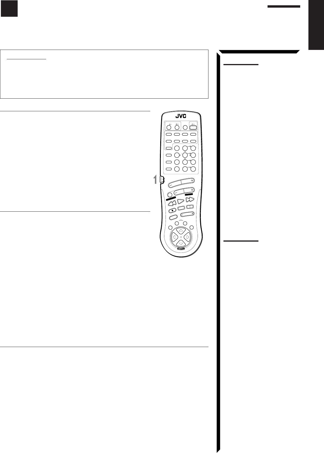
58
English
IMPORTANT:
To operate JVC’s audio components using this remote control:
• You need to connect JVC audio components through the COMPU LINK-3
(SYNCHRO) jacks (see page 50) in addition to the connections using cables
with RCA pin plugs (see page 9) or using digital cables (see page 12).
• Aim the remote control directly at the remote sensor on the receiver.
Tuner
After pressing FM/AM (with the remote control mode selector
set to “AUDIO/TV/VCR”), you can perform the following
operations:
FM/AM: Alternates between FM and AM.
1 – 10, +10: Selects a preset channel number directly.
For channel number 5, press 5. For
channel number 15, press +10, then 5.
For channel number 20, press +10, then
10.
TUNING UP/TUNING DOWN:
Tunes into stations.
FM MODE/MUTE: Changes the FM reception mode.
Sound control section (Amplifier)
You can always perform the following operations (with the
remote control mode selector set to “AUDIO/TV/VCR”):
SURROUND MODE: Changes the DSP modes.
After pressing SOUND CONTROL (with the remote control
mode selector set to “AUDIO/TV/VCR”), you can perform the
following operations:
SEA MODE: Changes the SEA modes.
SUBWOOFER +/–: Adjusts the subwoofer output level.
CNTR +/–: Adjusts the center speaker output
level.
REAR•L +/–: Adjusts the left rear speaker output
level.
REAR•R +/–: Adjusts the right rear speaker output level.
EFFECT: Selects the effect level.
TEST: Turns on or off the test tone output.
CNTR TONE: Selects the center tone.
CD player
After pressing CD (with the remote control mode selector set to “AUDIO/TV/VCR”),
you can perform the following operations on a CD player:
PLAY: Starts playing.
44
44
4:Returns to the beginning of the current (or previous) track.
¢¢
¢¢
¢:Skips to the beginning of the next track.
STOP: Stops playing.
PAUSE: Pauses playing. To release it, press PLAY.
1 – 10, +10: Selects a track number directly.
For track number 5, press 5. For track number 15, press +10, then 5. For
track number 20, press +10, then 10. For track number 30, press +10,
+10, then 10.
Notes:
• If you use the buttons on the
front panel or the menu
function to choose a source,
the remote control will not
operate that source. To
operate a source with the
remote control, the source
must be selected using
buttons on the remote control.
• Check to see if its remote
control mode selector is set to
the correct position. To
operate audio system, TVs,
and VCRs, set it to “AUDIO/
TV/VCR.”
• Refer also to the manuals
supplied with your
components.
Note:
After adjusting sounds, press
the corresponding source
selecting button or CD DISC to
operate your target source by
using 10 keys; otherwise, 10
keys cannot be used for
operating your target source.
RM-SR884XU REMOTE CONTROL
/DBS
SOUND
CONTROL
CD
DISC
VCR1
ANALOG
/DIGITAL
AUDIO
DVD VCR1 VIDEOVCR2
CD
TV/DBS
TEST
REAR R
REAR L
SEA MODE
SUBWOOFER
TAPE/MD FM/AMPHONO
546
213
87/P 9
0
+10
10
AUDIO/TV
/VCR
VCR1 TAPE
CONTROL
VOLUME
CHANNEL
MUTE
FF / ¢
PLAY
STOP
REC
TV/VIDEO
TV VOLUME
PAUSE
4 / REW
TV/CATV
CNTR
CNTR TONE
ENTER
MENU
EFFECT
CATV
/DBS
FM MODE/MUTE
100+
RETURN
SURROUND
MODE
O
N
S
C
R
E
E
N
C
O
N
T
R
O
L
SET EXIT
TUNING DOWN
TUNING UP
Operating JVC’s Audio/Video Components
You can operate JVC’s audio and video components with this receiver’s remote control, since control
signals for JVC components are preset in the remote control.
EN58_68.RX-884P[U]/1.PM5 98.2.23, 11:40 AM58
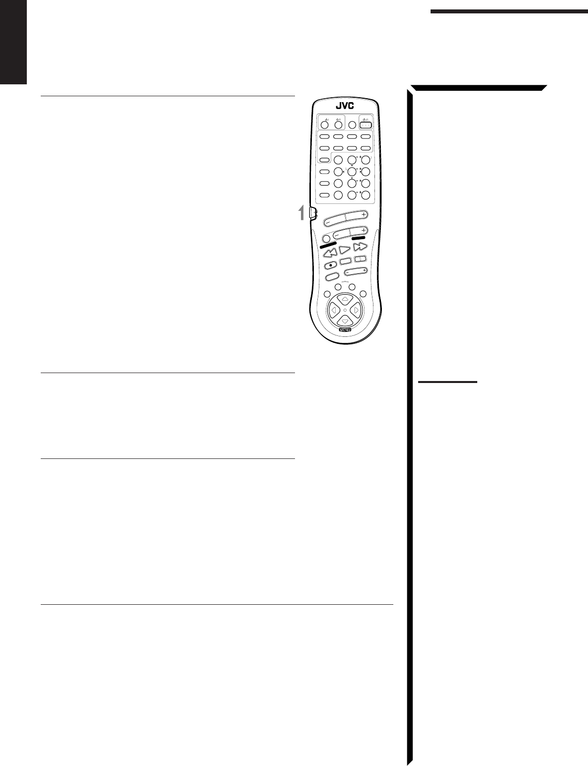
59
English
CD player-changer
After pressing CD DISC (with the remote control mode selector
set to “AUDIO/TV/VCR”), you can perform the following
operations on the CD player-changer:
PLAY: Starts playing.
44
44
4:Returns to the beginning of the current (or
previous) track.
¢¢
¢¢
¢:Skips to the beginning of the next track.
STOP: Stops playing.
PAUSE: Pauses playing. To release it, press the PLAY
button.
1 – 6, 7/P: Select the number of a disc installed in a CD
player-changer.
After pressing CD (with the remote control mode selector set to
“AUDIO/TV/VCR”), you can perform the following operations
on the CD player-changer:
1 – 10, +10: Selects a track number directly.
For track number 5, press 5. For track number
15, press +10, then 5. For track number 20,
press +10, then 10. For track number 30, press
+10, +10, then 10.
Turntable
After pressing PHONO (with the remote control mode selector
set to “AUDIO/TV/VCR”), you can perform the following
operations on the turntable:
PLAY: Starts playing.
STOP: Stops playing.
Cassette deck
After pressing TAPE/MD or TAPE CONTROL (with the
remote control mode selector set to “AUDIO/TV/VCR”), you
can perform the following operations on the cassette deck:
PLAY: Starts playing.
REW: Fast winds the tape from right to left.
FF: Fast winds the tape from left to right.
STOP: Stops operations.
PAUSE: Pauses playing or recording temporarily. To release it, press the PLAY button.
REC ¶¶
¶¶
¶:Press this button with the PLAY button to start recording.
Press this button with the PAUSE button to enter recording pause.
MD recorder
After pressing TAPE/MD or TAPE CONTROL (with the remote control mode selector
set to the “AUDIO/TV/VCR” position), you can perform the following operations on the
MD recorder:
PLAY: Starts playing.
44
44
4: Returns to the beginning of the current (or previous)
track.
¢¢
¢¢
¢: Skips to the beginning of the next track.
STOP: Stops playing.
PAUSE: Pauses playing. To release it, press the PLAY button.
REC ¶¶
¶¶
¶: Press this button with the PLAY button to start recording.
Press this button with the PAUSE button to enter recording pause.
RM-SR884XU REMOTE CONTROL
/DBS
SOUND
CONTROL
CD
DISC
VCR1
ANALOG
/DIGITAL
AUDIO
DVD VCR1 VIDEOVCR2
CD
TV/DBS
TEST
REAR R
REAR L
SEA MODE
SUBWOOFER
TAPE/MD FM/AMPHONO
546
213
87/P 9
0
+10
10
AUDIO/TV
/VCR
VCR1 TAPE
CONTROL
VOLUME
CHANNEL
MUTE
FF / ¢
PLAY
STOP
REC
TV/VIDEO
TV VOLUME
PAUSE
4 / REW
TV/CATV
CNTR
CNTR TONE
ENTER
MENU
EFFECT
CATV
/DBS
FM MODE/MUTE
100+
RETURN
SURROUND
MODE
O
N
S
C
R
E
E
N
C
O
N
T
R
O
L
SET EXIT
TUNING DOWN
TUNING UP
Operating JVC’s Audio/Video Components
Notes:
• To operate the cassette deck
or MD recorder using the
COMPU LINK remote control
system, set the source name
correctly. (See page 18.)
• You can use either the TAPE/
MD button or the TAPE
CONTROL button to activate
the buttons listed to the left. If
you press TAPE/MD, the
playing source also changes.
On the other hand, if you
press TAPE CONTROL, the
playing source does not
change.
EN58_68.RX-884P[U]/1.PM5 98.3.10, 3:58 PM59
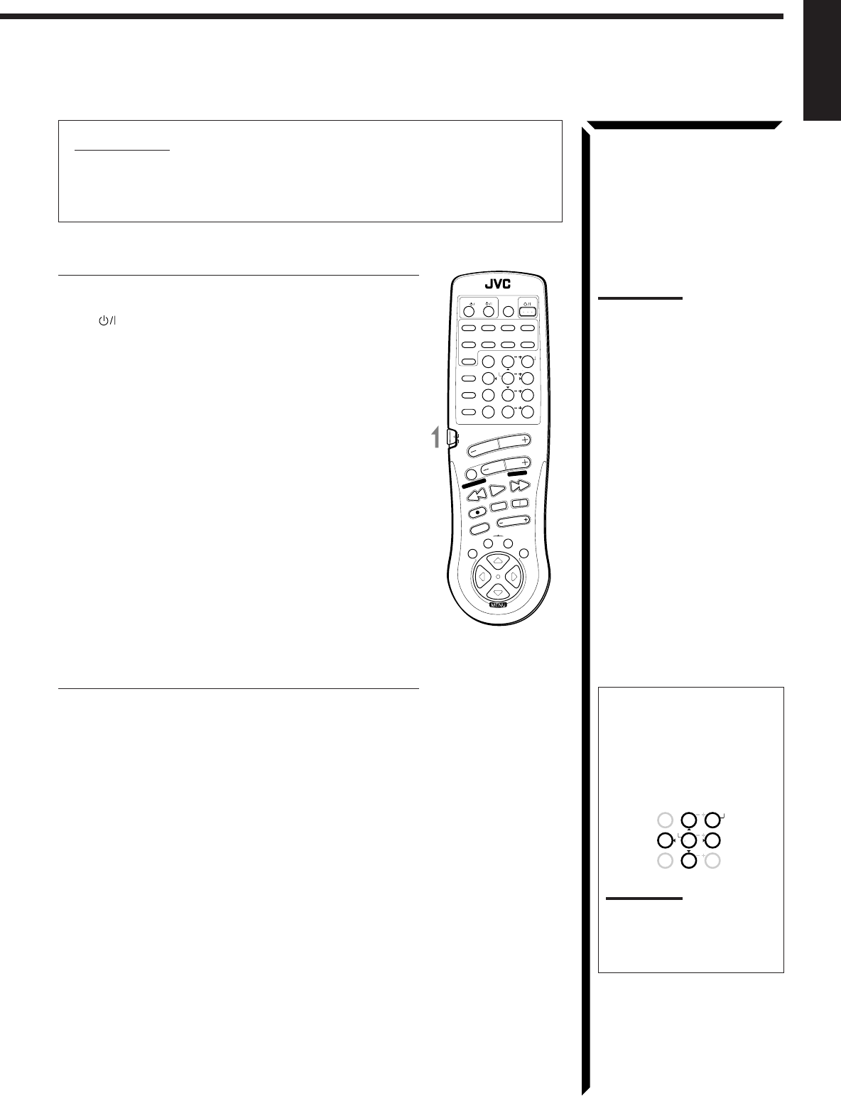
60
English
IMPORTANT:
To operate JVC’s video components using this remote control:
• Aim the remote control directly at the remote sensor on the VCR, DVD player or
TV, not on the receiver.
VCR1 (the VCR connected to the VCR1 jacks)
You can always perform the following operations (with the
remote control mode selector set to “AUDIO/TV/VCR”):
VCR1 : Turns on or off the VCR1.
After pressing VCR1 or VCR1 CONTROL (with the remote
control mode selector set to “AUDIO/TV/VCR”), you can
perform the following operations on the VCR:
PLAY: Starts playing.
REW: Rewinds a tape.
FF: Fast winds a tape.
STOP: Stops operations.
PAUSE: Pauses playing or recording temporarily. To
release it, press the PLAY button.
REC ¶¶
¶¶
¶:Press this button with the PLAY button to
start recording.
Press this button with the PAUSE button to
enter recording pause.
CHANNEL +/–: Changes the channels on the VCR.
1 – 9, 0: Selects the channels on the VCR.
For channel 5, press 5.
For channel 10, press 1, then 0.
DVD player
After pressing DVD (with the remote control mode selector set
to “AUDIO/TV/VCR”), you can perform the following
operations on a DVD player:
PLAY: Starts playing.
44
44
4:Returns to the beginning of the current (or
previous) track.
¢¢
¢¢
¢:Skips to the beginning of the next track.
STOP: Stops playing.
PAUSE: Stops playing temporarily. To release it, press the
PLAY button.
Notes:
• Some JVC VCRs can accept
two types of the control
signals – code “A” and “B.”
Before using this remote
control, make sure that the
remote control code of the
VCR1 is set to code “A.”
• You can use either the VCR1
button or the VCR1
CONTROL button to activate
the buttons listed to the left. If
you press VCR1, the playing
source also changes. On the
other hand, if you press VCR1
CONTROL, the playing source
does not change.
RM-SR884XU REMOTE CONTROL
/DBS
SOUND
CONTROL
CD
DISC
VCR1
ANALOG
/DIGITAL
AUDIO
DVD VCR1 VIDEOVCR2
CD
TV/DBS
TEST
REAR R
REAR L
SEA MODE
SUBWOOFER
TAPE/MD FM/AMPHONO
546
213
87/P 9
0
+10
10
AUDIO/TV
/VCR
VCR1 TAPE
CONTROL
VOLUME
CHANNEL
MUTE
FF / ¢
PLAY
STOP
REC
TV/VIDEO
TV VOLUME
PAUSE
4 / REW
TV/CATV
CNTR
CNTR TONE
ENTER
MENU
EFFECT
CATV
/DBS
FM MODE/MUTE
100+
RETURN
SURROUND
MODE
O
N
S
C
R
E
E
N
C
O
N
T
R
O
L
SET EXIT
TUNING DOWN
TUNING UP
After pressing DVD (with the
remote control mode selector
set to the “AUDIO/TV/VCR”
position), these buttons can
be used for the DVD menu
operations.
Note:
For detailed menu operations,
refer to the instructions
supplied with the discs or the
DVD player.
MENU
TEST
REAR R
REAR L
546
213
87/P 9
CNTR
CNTR TONE
ENTER
EFFECT
EN58_68.RX-884P[U]/1.PM5 98.3.10, 10:20 AM60
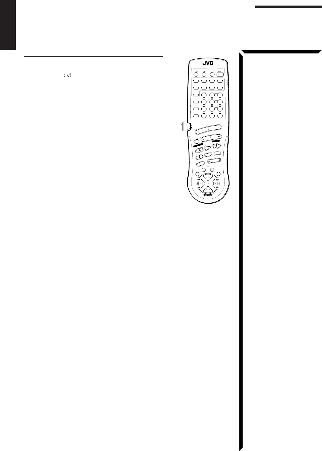
61
English
TV
You can always perform the following operations (with the
remote control mode selector set to “AUDIO/TV/VCR”):
TV/CATV/DBS : Turns on or off the TV.
TV VOLUME +/–: Adjusts the volume.
TV/VIDEO: Sets the input mode (either TV or
VIDEO).
After pressing TV/DBS (with the remote control mode selector
set to “AUDIO/TV/VCR”), you can perform the following
operations on a TV:
CHANNEL +/–: Changes the channels.
1 – 9, 0, 100+: Selects the channels.
RETURN: Alternates between the previously
selected channel and the current channel.
Operating JVC’s Audio/Video Components
RM-SR884XU REMOTE CONTROL
/DBS
SOUND
CONTROL
CD
DISC
VCR1
ANALOG
/DIGITAL
AUDIO
DVD VCR1 VIDEOVCR2
CD
TV/DBS
TEST
REAR R
REAR L
SEA MODE
SUBWOOFER
TAPE/MD FM/AMPHONO
546
213
87/P 9
0
+10
10
AUDIO/TV
/VCR
VCR1 TAPE
CONTROL
VOLUME
CHANNEL
MUTE
FF / ¢
PLAY
STOP
REC
TV/VIDEO
TV VOLUME
PAUSE
4 / REW
TV/CATV
CNTR
CNTR TONE
ENTER
MENU
EFFECT
CATV
/DBS
FM MODE/MUTE
100+
RETURN
SURROUND
MODE
O
N
S
C
R
E
E
N
C
O
N
T
R
O
L
SET EXIT
TUNING DOWN
TUNING UP
EN58_68.RX-884P[U]/1.PM5 98.2.24, 2:03 PM61
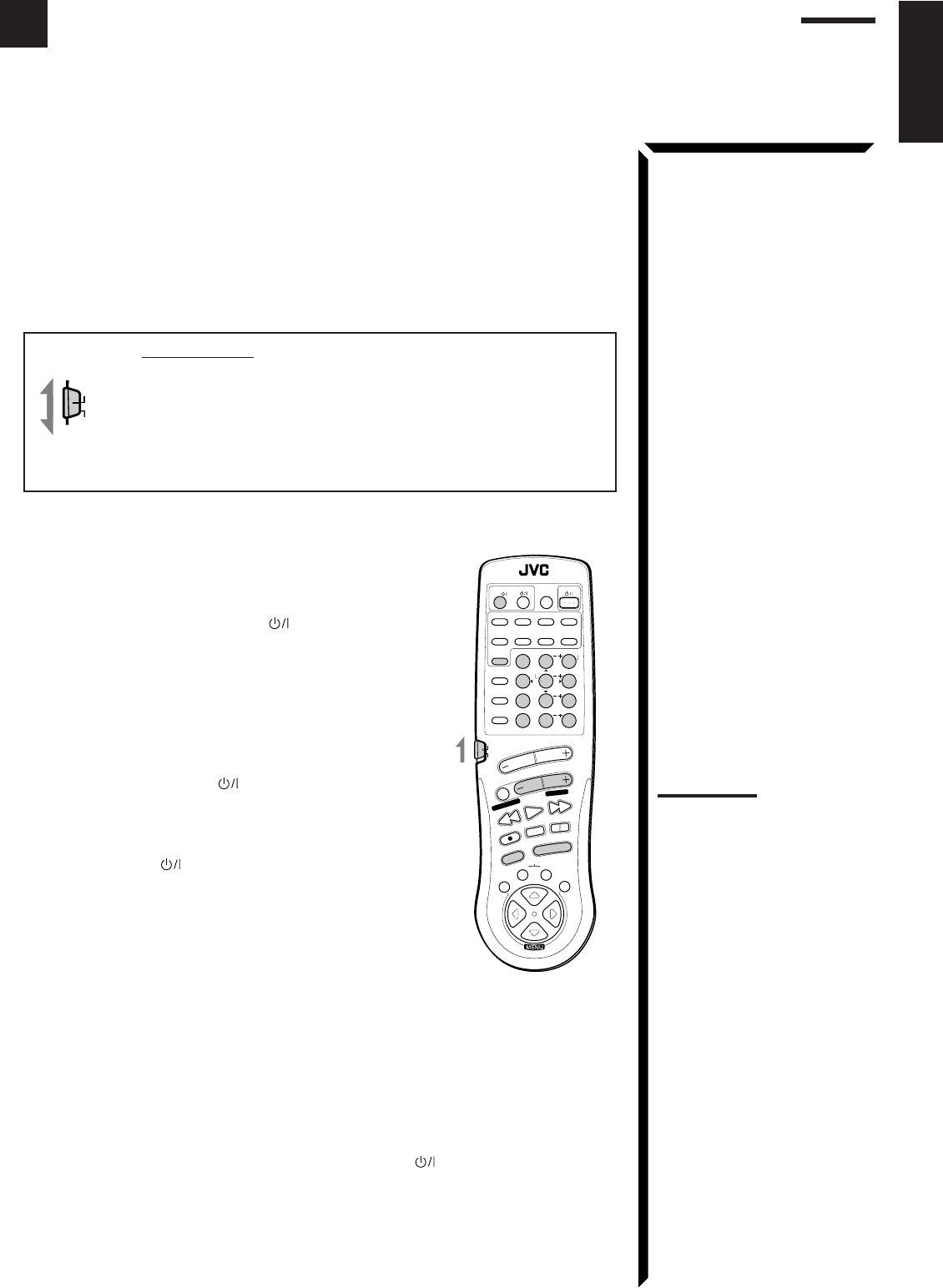
62
English
This remote control supplied with the receiver can transmit control signals for other
manufacturers’ VCRs, TVs, CATV converters and DBS tuners. By changing the
transmittable signals from preset ones to the other manufacturers’, you can operate the
other manufacturer’s components using this remote control.
When operating the other manufacturers’ components, refer also to the manuals
supplied with them.
To operate these components with the remote control, first you need to set the
manufacturer’s code each for the VCR, TV, CATV converter, and DBS tuner.
IMPORTANT:
When using the Remote Control, check to see if its remote control
mode selector is set to the correct position:
To operate an audio system, TV, and VCR, set it to “AUDIO/TV/
VCR.”
To operate a CATV converter and DBS tuner, set it to “CATV/
DBS.”
To change the transmittable signals for operating another
manufacturer’s TV
1. Set the remote control mode selector to “AUDIO/TV/
VCR.”
2. Press and hold TV/CATV/DBS .
3. Press TV/DBS.
4. Enter the manufacturer’s code (three digits) using
buttons 1 – 9, and 0.
See the lists on page 65 to find the code.
5. Release TV/CATV/DBS .
The following buttons can be used for operating the TV
(with the remote control mode selector set to “AUDIO/TV/
VCR”):
TV/CATV/DBS : Turns on and off TV.
TV VOLUME +/–: Adjusts the volume.
TV/VIDEO: Sets the input mode (either TV or
VIDEO).
After pressing TV/DBS (with the remote control mode
selector set to “AUDIO/TV/VCR”), you can perform the
following operations on the TV:
CHANNEL +/–: Changes the channels.
1 – 10, 0, 100+(+10): Selects the TV channels.
100+(+10) button will function as the
ENTER button if your TV requires
pressing ENTER after selecting a
channel number.
6. Try to operate your TV by pressing TV/CATV/DBS .
When your TV turns on or off, you have entered the correct code.
7. If there are more than one code listed for your brand of TV, try each one until
the correct one is entered.
Note:
Refer also to the manual
supplied with your TV.
AUDIO/TV
/VCR
CATV
/DBS
RM-SR884XU REMOTE CONTROL
/DBS
SOUND
CONTROL
CD
DISC
VCR1
ANALOG
/DIGITAL
AUDIO
DVD VCR1 VIDEOVCR2
CD
TV/DBS
TEST
REAR R
REAR L
SEA MODE
SUBWOOFER
TAPE/MD FM/AMPHONO
546
213
87/P 9
0
+10
10
AUDIO/TV
/VCR
VCR1 TAPE
CONTROL
VOLUME
CHANNEL
MUTE
FF / ¢
PLAY
STOP
REC
TV/VIDEO
TV VOLUME
PAUSE
4 / REW
TV/CATV
CNTR
CNTR TONE
ENTER
MENU
EFFECT
CATV
/DBS
FM MODE/MUTE
100+
RETURN
SURROUND
MODE
O
N
S
C
R
E
E
N
C
O
N
T
R
O
L
SET EXIT
TUNING DOWN
TUNING UP
Operating Other Manufactures’ Components
EN58_68.RX-884P[U]/1.PM5 98.2.24, 2:03 PM62
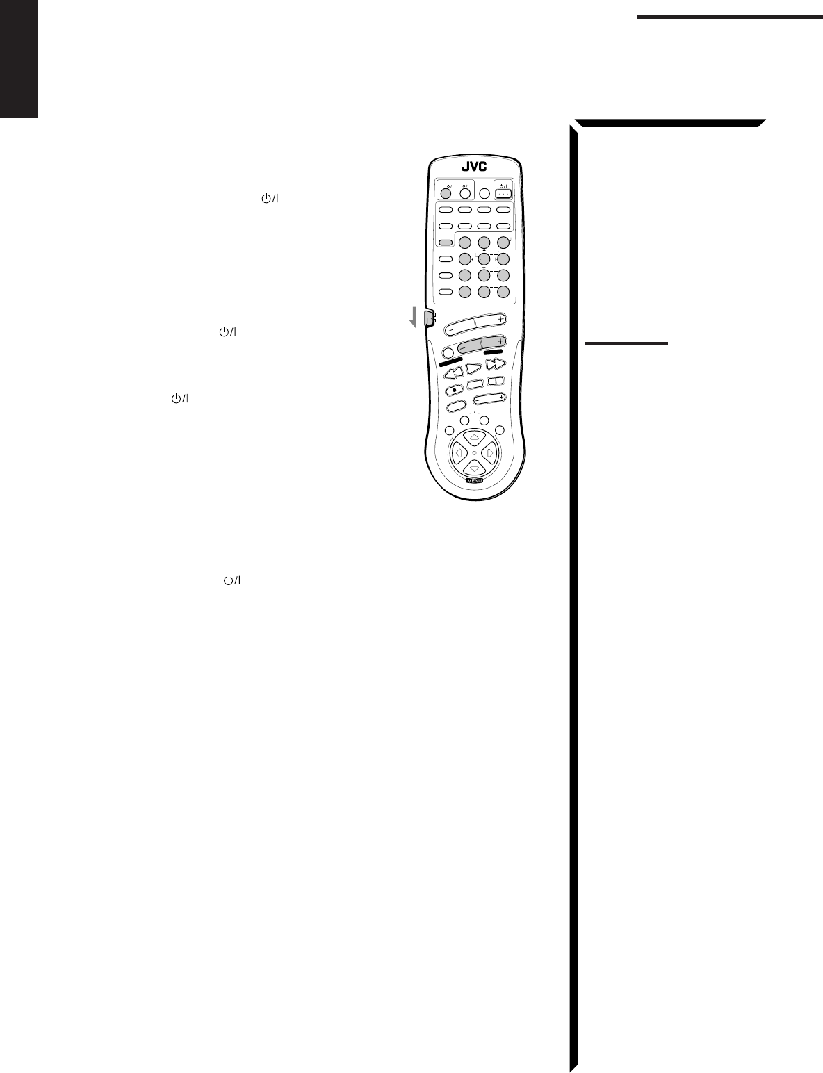
63
English
To change the transmittable signals for operating a CATV
converter or DBS tuner
1. Set the remote control mode selector to “CATV/DBS.”
2. Press and hold TV/CATV/DBS .
3. Press TV/DBS.
4. Enter the manufacturer’s code (three digits) using
buttons 1 – 9, and 0.
See the lists on page 65 to find the code.
5. Release TV/CATV/DBS .
After setting the remote control mode selector to “CATV/
DBS,” you can perform the following operations on the
CATV converter or on the DBS tuner:
TV/CATV/DBS : Turns on and off the CATV
converter or DBS tuner.
CHANNEL +/–: Changes the channels.
1 – 10, 0, 100+(+10): Selects the channels.
100+(+10) button will function
as the ENTER button if your
CATV converter or DBS tuner
requires pressing ENTER after
selecting a channel number.
6. Try to operate your CATV converter or DBS tuner by
pressing TV/CATV/DBS .
When your CATV converter or DBS tuner turns on or off, you have entered the
correct code.
7. If there are more than one code listed for your brand of CATV converter or
DBS tuner, try each one until the correct one is entered.
Note:
Refer also to the manual
supplied with your CATV
converter or DBS tuner.
RM-SR884XU REMOTE CONTROL
/DBS
SOUND
CONTROL
CD
DISC
VCR1
ANALOG
/DIGITAL
AUDIO
DVD VCR1 VIDEOVCR2
CD
TV/DBS
TEST
REAR R
REAR L
SEA MODE
SUBWOOFER
TAPE/MD FM/AMPHONO
546
213
87/P 9
0
+10
10
AUDIO/TV
/VCR
VCR1 TAPE
CONTROL
VOLUME
CHANNEL
MUTE
FF / ¢
PLAY
STOP
REC
TV/VIDEO
TV VOLUME
PAUSE
4 / REW
TV/CATV
CNTR
CNTR TONE
ENTER
MENU
EFFECT
CATV
/DBS
FM MODE/MUTE
100+
RETURN
SURROUND
MODE
O
N
S
C
R
E
E
N
C
O
N
T
R
O
L
SET EXIT
TUNING DOWN
TUNING UP
Operating Other Manufactures’ Components
EN58_68.RX-884P[U]/1.PM5 98.2.24, 2:03 PM63
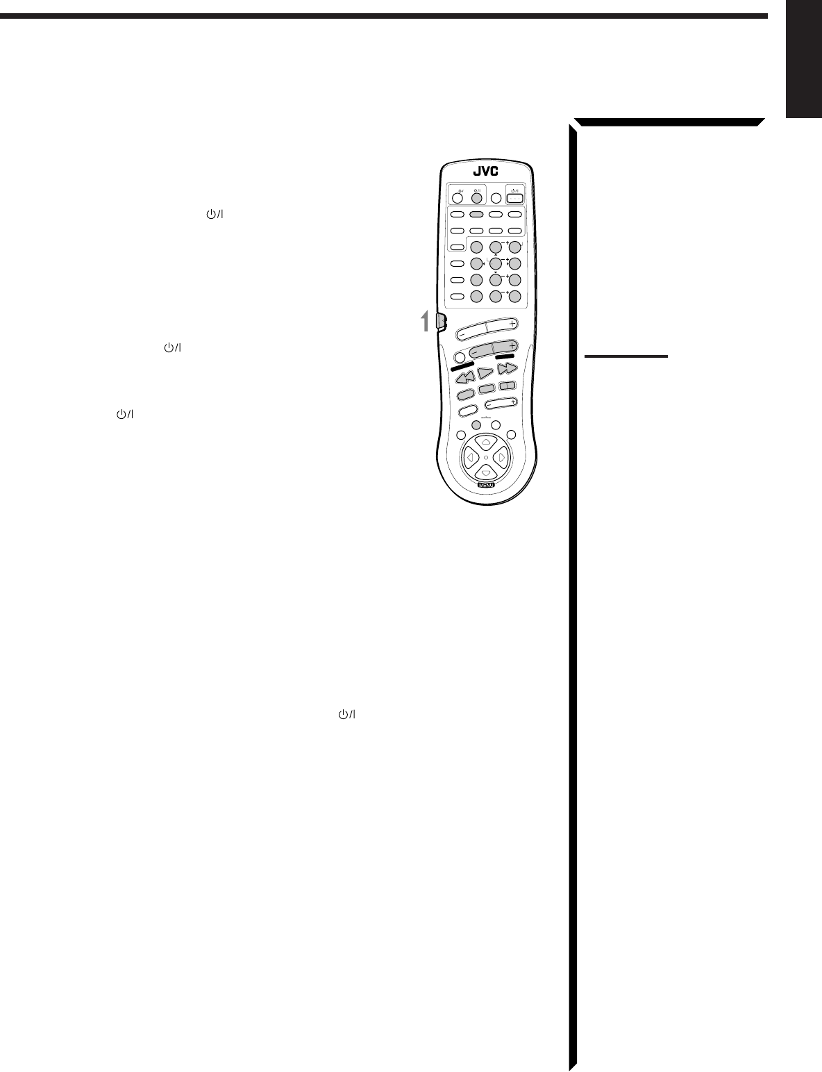
64
English
To change the transmittable signals for operating another
manufacturer’s VCR
1. Set the remote control mode selector to “AUDIO/TV/
VCR.”
2. Press and hold VCR1 .
3. Press VCR1.
4. Enter the manufacturer’s code (three digits) using
buttons 1 – 9, and 0.
See the lists on page 65 to find the code.
5. Release VCR1 .
The following buttons can be used for operating the VCR
(with the remote control mode selector set to “AUDIO/TV/
VCR”):
VCR1 : Turns on and off VCR.
After pressing VCR1 or VCR1 CONTROL (with the remote
control mode selector set to “AUDIO/TV/VCR”), you can
perform the following operations on the VCR:
CHANNEL +/–: Changes the channels on the VCR.
1 – 10, 0, 100+(+10): Selects the channels on the VCR.
100+(+10) button will function as
the ENTER button if your VCR
requires pressing ENTER after
selecting a channel number.
PLAY: Starts playback.
STOP: Stops operations.
PAUSE: Pauses.
REW: Rewinds a tape.
FF: Fast winds a tape.
REC ¶¶
¶¶
¶:Starts recording or enters recording pause.
6. Try to operate your VCR by pressing VCR1 .
When your VCR turns on or off, you have entered the correct code.
7. If there are more than one code listed for your brand of VCR, try each one until
the correct one is entered.
Notes:
• You can use either the VCR1
button or the VCR1 CONTROL
button to activate the buttons
listed to the left. If you press
VCR1, the playing source also
changes. On the other hand, if
you press VCR1 CONTROL,
the playing source does not
change.
• Refer also to the manual
supplied with your VCR.
RM-SR884XU REMOTE CONTROL
/DBS
SOUND
CONTROL
CD
DISC
VCR1
ANALOG
/DIGITAL
AUDIO
DVD VCR1 VIDEOVCR2
CD
TV/DBS
TEST
REAR R
REAR L
SEA MODE
SUBWOOFER
TAPE/MD FM/AMPHONO
546
213
87/P 9
0
+10
10
AUDIO/TV
/VCR
VCR1 TAPE
CONTROL
VOLUME
CHANNEL
MUTE
FF / ¢
PLAY
STOP
REC
TV/VIDEO
TV VOLUME
PAUSE
4 / REW
TV/CATV
CNTR
CNTR TONE
ENTER
MENU
EFFECT
CATV
/DBS
FM MODE/MUTE
100+
RETURN
SURROUND
MODE
O
N
S
C
R
E
E
N
C
O
N
T
R
O
L
SET EXIT
TUNING DOWN
TUNING UP
EN58_68.RX-884P[U]/1.PM5 98.2.20, 2:05 PM64

65
English
Manufacturers’ codes for TV
Anam 003, 004, 009, 068, 161, 425, 426
Anam National 161, 250, 425
Blaupunkt 554
Daewoo 066, 092, 154, 391, 402, 451
ECE 037
Etron 009, 283
Fortress 093
Funai 264, 342
General 186
GoldStar 002, 037, 039, 178, 283, 457, 467
Grundig 535
Hitachi 145
JVC 036, 053, 069, 094, 160
Marantz 054
Matsushita 250
Mitsubishi 150, 241
National 226
NEC 030, 170
Nicamagic 216
Panasonic 161, 250
Philips 037
Pioneer 166
Samsung 060, 090, 427
Sanyo 208, 376, 424
Sharp 093, 256
Sony 000
Telefunken 252
Thomson 560
Toshiba 156, 502
Victor 036, 053, 160, 250, 376
Manufacturers’ codes for VCR
Akai 281, 288
Anam 037, 162, 226, 240, 278
Anam National 162, 226
Blaupunkt 226
Daewoo 020, 046, 278, 368, 552
Funai 000
General 052
GoldStar 037, 225, 471
Grundig 195
Hitachi 042, 166, 235
JVC 008, 041, 067, 384
Marantz 081
Matsushita 227
Mitsubishi 043, 061, 196
National 226
NEC 038, 040, 370
Panasonic 162, 226, 227, 367
Philips 062, 081
Pioneer 058
Samsung 240, 426, 432
Sanyo 046, 104, 368, 369
Sharp 048, 062, 363
Shintom 072
Sony 032, 033, 034
Telefunken 187
Thomson 320
Toshiba 045, 366
Victor 008, 041, 067, 384
Manufacturers’ codes listed on this page are subject to
change without notice. If they are changed, this remote
control cannot operate the equipment.
Manufacturers’ codes for CATV converters
Daeryung 008
GoldStar 838
LG Alps 779
Now 776
Samsung 702
Seawoo 780
Tongkook 777, 840
Zenith 000
Manufacturers’ codes for DBS tuner
Dae Young 735
DX Antenna 752
Marantz 200
Panasonic 739
Pantech 747
Samsung 773
Sony 661
Toshiba 486
EN58_68.RX-884P[U]/1.PM5 98.2.20, 2:05 PM65

66
English
Troubleshooting
Use this chart to help you solve daily operational problems. If there is any problem you cannot solve,
contact your JVC service center.
PROBLEM
The display does not light up.
No sound from speakers.
Sound from one speaker only.
Continuous hiss or buzzing during FM
reception.
Occasional cracking noise during FM
reception.
No color on the on-screen display.
Howling during record playing.
“OVERLOAD” starts flashing on the
display.
Remote control does not work.
SOLUTION
Plug the power cord into an AC
outlet and/or press POWER to
set it in the _ON position.
Check speaker wiring and
reconnect if necessary.
Press SPEAKERS 1 and 2 correctly.
Select the correct source.
Press MUTE to cancel the mute.
Check speaker wiring and reconnect
if necessary.
Adjust the balance properly (see
page 19).
Connect an outside FM antenna or
contact your dealer.
Select a new station.
Check with your dealer to be sure
you have the correct antenna.
Check connections.
Move the antenna farther from
automobile traffic.
Connect a PAL TV.
Move speakers away from the
turntable.
Rotate the MASTER VOLUME
control counterclockwise three or
four times, then press STANDBY/
ON on the front panel.
If “OVERLOAD” does not
disappear, unplug the AC power
cord, then plug it back again.
Press STANDBY/ON on the
front panel, then check the speaker
wiring.
If “OVERLOAD” does not
disappear, unplug the AC power
cord, then plug it back again.
If speaker wiring is not short-
circuited, contact your dealer.
Set the selector correctly either to
“AUDIO/TV/VCR” or to “CATV/
DBS.”
Remove the obstruction.
Replace batteries.
POSSIBLE CAUSE
The power cord is not plugged in or the
POWER switch pressed to set it in the
—OFF position.
Speaker signal cables are not connected.
The SPEAKERS 1 and 2 buttons are not
set correctly.
An incorrect source is selected.
Muting is activated.
Speaker signal cables are not connected
properly.
The balance is set to one extreme.
Incoming signal is too weak.
The station is too far away.
An incorrect antenna is used.
Antennas are not connected properly.
Ignition noise from automobiles.
The color system of the connected TV is
not PAL
Your turntable is too close to speakers.
Speakers are overloaded because of high
volume.
Speakers are overloaded because of short
circuit of speaker terminals.
The remote control mode selector is not set
correctly.
There is an obstruction in front of the
remote sensor on the receiver.
Batteries are weak.
EN58_68.RX-884P[U]/1.PM5 98.2.20, 2:05 PM66

67
English
Specifications
Amplifier
Output Power ....................................................... At Stereo operation
Front channels ............................................................. 100 watts per channel, min. RMS,
driven into 4 ohms at 1 kHz, with
no more than 0.7 % total harmonic
distortion. (IEC268-3/DIN)
50 watts per channel, min. RMS,
driven into 8 ohms at 1 kHz, with
no more than 0.7 % total harmonic
distortion. (IEC268-3/DIN)
At Surround operation
Front channels ............................................................. 70 watts per channel, min. RMS,
driven into 4 ohms at 1 kHz, with
no more than 0.8 % total harmonic
distortion.
Center channel............................................................. 70 watts, min. RMS, driven into
4 ohms at 1 kHz, with no more than
0.8 % total harmonic distortion.
Rear channels .............................................................. 70 watts per channel, min. RMS,
driven into 4 ohms at 1 kHz, with
no more than 0.8 % total harmonic
distortion.
Total Harmonic Distortion (8 ohms, 1 kHz) .............................................................................................. 0.02 %* at 50 watts output
(* Measured by JVC Audio
Analysis System)
Audio Input Sensitivity/Impedance (1 kHz)........ PHONO (MM) ............................................................ 2.5 mV/47 k ohms
CD, TAPE/MD, TV SOUND/DBS, VCR1, VCR2, VIDEO, DVD
...................................................... 200 mV/47 k ohms
Audio Input (DIGITAL IN)................................. Coaxial: DIGITAL 1 (DBS) ....................................... 0.5 Vp-p/75 ohms
Optical: DIGITAL 2 (DVD), DIGITAL 3 (CD) ......... –21 dBm to –15 dBm (660 nm ±30
nm)
Audio Output Level ............................................. TAPE/MD, VCR1, VCR2 ........................................... 200 mV
Signal-to-Noise Ratio (’66 IHF/DIN) ................. PHONO ....................................................................... 70 dB/66 dB
CD, TAPE/MD, TV SOUND/DBS, VCR1, VCR2, VIDEO, DVD
...................................................... 87 dB/67 dB
Frequency Response (8 ohms)............................. PHONO ....................................................................... 20 Hz to 20 kHz (±1 dB)
CD, TAPE/MD, TV SOUND/DBS, VCR1, VCR2, VIDEO, DVD
...................................................... 20 Hz to 20 kHz (±1 dB)
RIAA Phono Equalization .......................................................................................................................... ±0.5 dB (20 Hz to 20 kHz)
Loudness Control (Volume Control at –30 dB) ......................................................................................... +6 ±1 dB at 100 Hz
..................................................................................... +4 ±1 dB at 10 kHz
S.E.A.................................................................... Center Frequencies ...................................................... 100 Hz, 1 kHz, 10 kHz
Control Range ............................................................. ±10 dB ±2 dB
EN58_68.RX-884P[U]/1.PM5 98.3.16, 2:55 PM67

68
English
Video
Video Input Sensitivity/Impedance ..................... Composite video: TV SOUND/DBS, VCR1, VCR2, VIDEO, DVD
...................................................... 1 Vp-p/75 ohms
S-video: TV SOUND/DBS, VCR1, VIDEO, DVD
(Y: luminance): ........................................................ 1 Vp-p/75 ohms
(C: chrominance, burst): .......................................... 0.286 Vp-p/75 ohms
Video Output Level ............................................. Composite video: VCR1, VCR2, MONITOR OUT ... 1 Vp-p/75 ohms
S-video: VCR1, MONITOR OUT .............................. 1 Vp-p/75 ohms
(Y: luminance): ........................................................ 1 Vp-p/75 ohms
(C: chrominance, burst): .......................................... 0.286 Vp-p/75 ohms
Synchronization .......................................................................................................................................... Negative
Signal-to-Noise Ratio ................................................................................................................................. 45 dB
On-Screen Color System ............................................................................................................................ PAL
FM tuner (IHF)
Tuning Range ............................................................................................................................................. 87.5 MHz to 108.0 MHz
Usable Sensitivity ................................................ Monaural ..................................................................... 12.7 dBf (1.2 µV/75 ohms)
50 dB Quieting Sensitivity .................................. Monaural ..................................................................... 16.3 dBf (1.8 µV/75 ohms)
Stereo .......................................................................... 38.3 dBf (22.5 µV/75 ohms)
Signal-to-Noise Ratio (IHF-A weighted) ............ Monaural ..................................................................... 80 dB at 85 dBf
Stereo .......................................................................... 73 dB at 85 dBf
Total Harmonic Distortion .................................. Monaural ..................................................................... 0.15 % at 1 kHz
Stereo .......................................................................... 0.2 % at 1 kHz
Stereo Separation at REC OUT .................................................................................................................. 40 dB at 1 kHz
Capture Ratio .............................................................................................................................................. 1.5 dB at 85 dBf
Alternate Channel Selectivity ..................................................................................................................... 60 dB: (±400 kHz)
Frequency Response ................................................................................................................................... 30 Hz to 15 kHz: (+0.5 dB, –3 dB)
AM tuner
Tuning Range ............................................................................................................................................. 531 kHz to 1,602 kHz (at 9 kHz
interval)
530 kHz to 1,600 kHz (at 10 kHz
interval)
Usable Sensitivity ................................................ Loop antenna ............................................................... 300 µV/m
Signal-to-Noise Ratio ................................................................................................................................. 50 dB (100 mV/m)
General
Power Requirements................................................................................................................................... AC 110/127/220/230–240V ,
adjustable with the voltage selector,
50/60 Hz
Power Consumption ................................................................................................................................... 280 watts
2 watts (in standby mode)
Dimensions (W x H x D) ............................................................................................................................ 435 x 157 x 412.5 mm
(17 3/16 x 6 3/16 x 16 1/4 inches)
Mass............................................................................................................................................................ 11.3 kg (25.0 lbs)
Designs & specifications are subject to change without notice.
EN58_68.RX-884P[U]/1.PM5 98.3.13, 4:21 PM68

0398OFMMDWJEM
EN, SP, PR, CH
Mains (AC) Line Instruction (not applicable for Europe, U.S.A., Canada, Australia
and U.K.)
Instrucción sobre la línea de la red (CA) (no aplicable para Europa, EE.UU.,
Canadá, Australia, ni el Reino Unido)
Instrução sobre a tensão da rede eléctrica (CA) (não aplicável para a Europa, os
E.U.A., o Canadá, a Austrália e o Reino Unido)
VICTOR COMPANY OF JAPAN, LIMITED
IMPORTANT for mains (AC) line
BEFORE PLUGGING IN, do check that your mains (AC)
line voltage corresponds with the position of the voltage
selector switch provided on the outside of this equipment
and, if different, reset the voltage selector switch, to prevent
from a damage or risk of fire/electric shock.
IMPORTANTE para la línea de la red (CA)
ANTES DE ENCHUFAR EL EQUIPO, compruebe si la
tensión de la línea de la red (CA) corresponde con la posición
del selector de tensión situado en la parte exterior del equipo,
y si es diferente, reajuste el selector de tensión para evitar el
riesgo de incendios/ descargas eléctricas.
LINE VOLTS
IMPORTANTE para a ligação à tensão da rede (CA)
ANTES DE LIGAR O APARELHO A UMA TOMADA DA
REDE, verifique se a tensão da rede CA corresponde à posição
do selector de voltagem localizado na parte externa deste
equipamento. Caso não corresponda, reajuste o selector de
voltagem a fim de evitar avarias ou riscos de incêndio e choque
eléctrico.
J
V
C
RX-884P[U]COVER 98.2.20, 2:52 PM2
