Jvc Stereo Receiver Rx D401 Users Manual Microsoft RX_D702_tec_guide [Read Only]
JVC Stereo Receiver RX-D401 RX-D702 - Tech Guide
RX-D702 to the manual f7e34256-a745-4e42-bcff-d61f793cfce2
2015-01-23
: Jvc Jvc-Stereo-Receiver-Rx-D401-Users-Manual-325148 jvc-stereo-receiver-rx-d401-users-manual-325148 jvc pdf
Open the PDF directly: View PDF ![]() .
.
Page Count: 63
< 1 >
< 2 >
High
High-
-Power 7.1
Power 7.1-
-Channel A/V Control Receivers
Channel A/V Control Receivers --
--
A Host of Digital Technologies Applied for
A Host of Digital Technologies Applied for
Superior Sound, Pictures, and Style.
Superior Sound, Pictures, and Style.
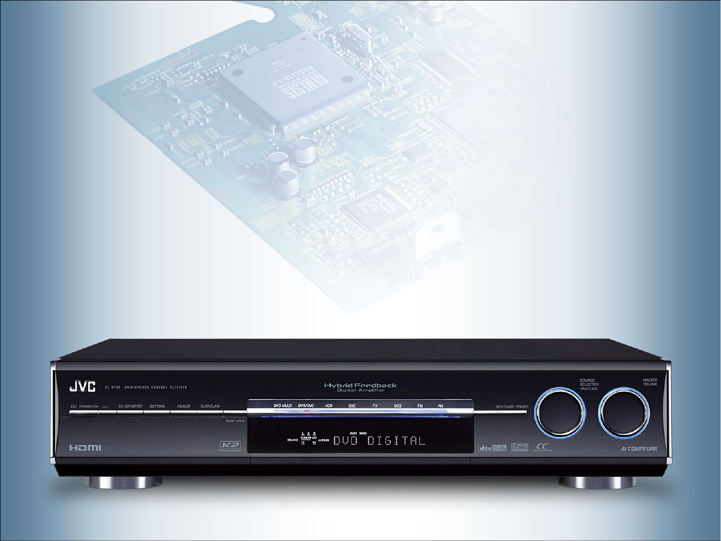
JVC now offers the latest-generation of AV control receivers -- RX-D702, RX-D402, and RX-D401 --
which feature a sleek profile to complement today’s and future home cinema systems.
But what gears the units for the future home cinema is not only the stylish design.
Despite the slim dimensions, the units are ready to deliver powerful, high-quality sound from
various sources -- including PC music files -- and provide superior picture quality, too.
What’s more, their expanded connectivity lets you easily connect the units with your PC, and
even permits HDMI connections -- the latest interface for transmitting audio/video signals.
Enabling these and many other feats are a host of advanced
digital technologies newly incorporated into the units.
In this technical guide, you will see the details of those technologies and find
how the advanced A/V receivers will upgrade your digital home theater systems.

< 3 >
High-Quality Pictures -- Advanced Technologies that Even Permit HDMI
Compatibility
1
PC Link -- USB Connection for Receiving Uncompressed PCM Data from
PC
2
CC Converter -- A JVC-Original Technology for Superior Sound
3
Aureus™ -- High-Performance DSP for Superior Sound Quality
4
Design Concepts
Design Concepts
Hybrid Feedback Digital Amplifier Ver.III -- An Upgraded Version of
JVC-Trademark Digital Amp for Unmatched Sound Quality
5
< 4 >
High-Quality Pictures
HDMI
HDMI
DCDi
DCDi by FAROUDJA
by FAROUDJA
1
HDMI -- The Next-Generation Digital Interface
HDMI -- Easy Connections for All-Digital Transmission
Connection Example -- RX-D702
Connection Example -- RX-D702
Effect Examples (1) 10
07
06
05
Effect Examples (2) 11
The JVC A/V receivers deliver not only
superior sound, but also superb pictures with
a host of advanced technologies. The units
feature HDMI terminals and use of DCDi by
FAROUDJA.
Connection Example -- RX-D402/RX-D401
Connection Example -- RX-D402/RX-D401 08
What is DCDi by FAROUDJA?
What is DCDi by FAROUDJA? 09
< 5 >
HDMI
HDMI
HDMI -- The Next-Generation Digital Interface
HDMI -- The Next-Generation Digital Interface
HDMI Founders
Hitachi
Matsushita (MEI)
Philips
Silicon Image
SONY
Thomson Multimedia
Toshiba
Digital
Analog
Consumer AVPCConsumer AVApplication
YPbPr/RGBRGBYPbPrSignal Format
YesYes-Content Protection
Yes--Remote Control
22Audio
Video
YesYes-PC Compatibility
1
13
Cable
HDMIDVI
Component Video
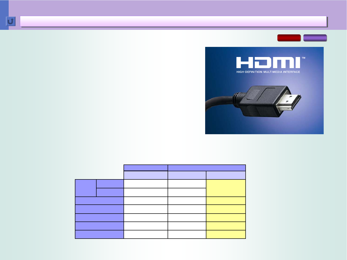
HDMI (High-Definition Multimedia Interface) -- An
Industry-Supported, Digital Audio/Video Interface
Developed for Next-Generation Home AV Devices.
Its remarkable benefits include:
1. All digital provides the highest quality available --
HDMI is the only interface in the industry that can handle both
uncompressed high-definition video and uncompressed multi-
channel audio. Supported HD video formats include 720p, 1080i
and even upcoming 1080p.
2. A single-cable connection for transmission of high-quality
audio and video signals
3. HDCP (High-bandwidth Digital Content Protection) is
supported
RX-D702 RX-D402
*Also applies to RX-D401
< 6 >
HDMI
HDMI
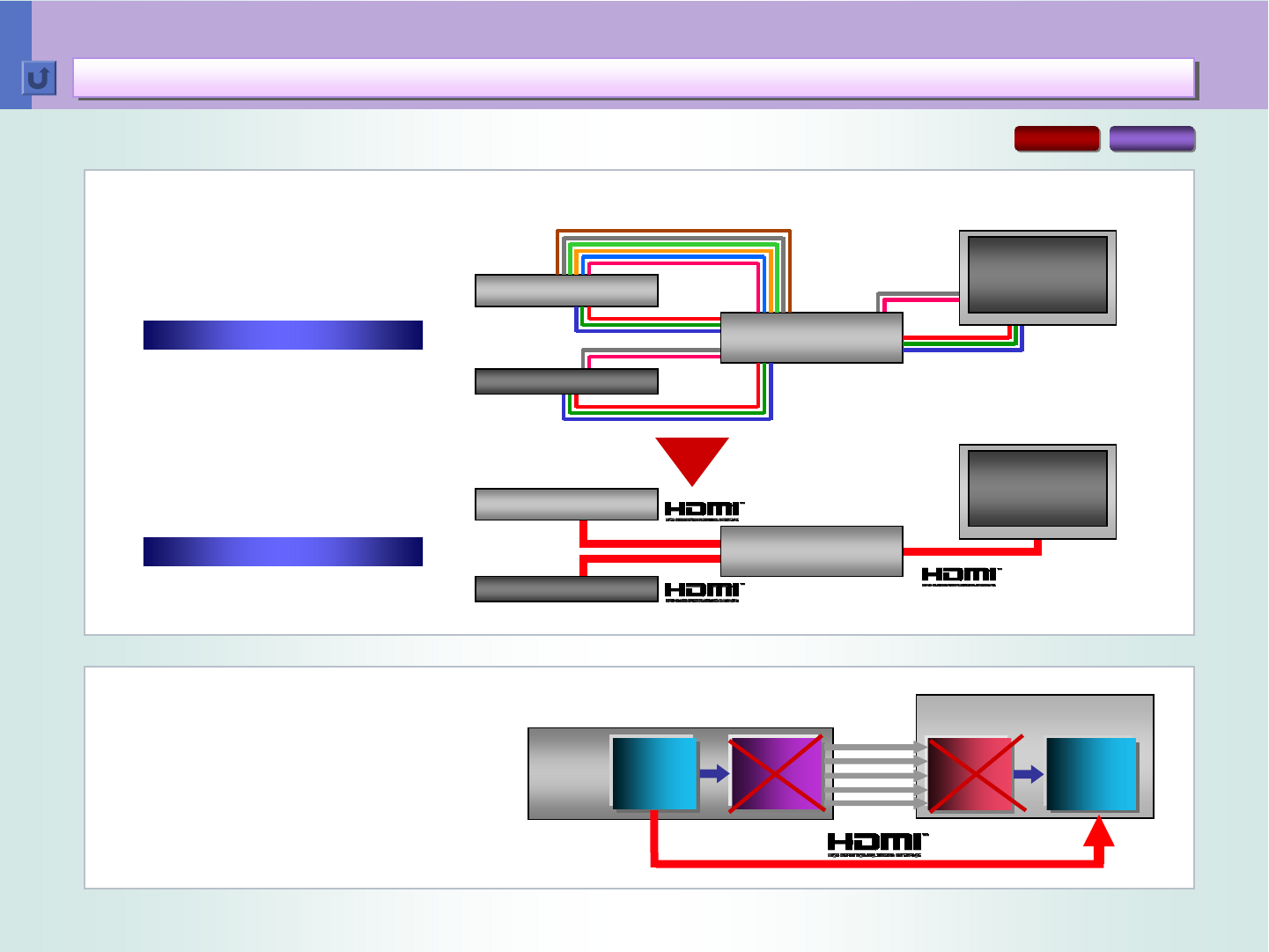
HDMI -- Easy Connections for All-Digital Transmission
HDMI -- Easy Connections for All-Digital Transmission
D/A
D/A
Converter
Converter
Digital
Digital
Display
Display
Digital
Digital
A/D
A/D
Converter
Converter
Receiver
All-Digital Transmission of
High-Quality Video & Audio
Even System Control is
available
3 HDMI Cables
DVD Player
STB
Receiver
Display
10 Audio + 9 Video Cables Receiver
Display
5.1-ch Audio
2-ch Audio
Component Video
DVD Player
STB
Single-Cable Connections
RX-D702 RX-D402
*Also applies to RX-D401
< 7 >
DCDi
DCDi by FAROUDJA
by FAROUDJA
DSP
DSP
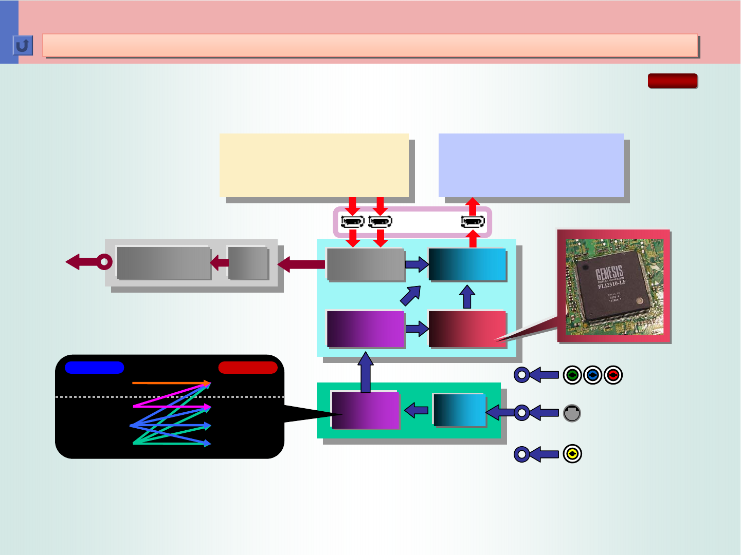
FAROUDJA
Display
Up
Up
Converter
Converter
I/P
I/P
Conversion
Conversion
HDMI
Component
A/D
A/D
Converter
Converter
OSD
OSD
TX
TX
RX
RX
S-Video
Composite
480pHD, 480p
480i/p
Y Pb Pr
Speakers
480i/p, 720p, 1080i
480i/p, 720p, 1080i
PCM (DVD-Audio) / DD / DTS
DVD/VDR/D-VHS/STB
DVD-Audio
SPDIF
....
....
Component Component
HDMI HDMI
S-Video S-Video
Composite Composite
Inputs Outputs
Connection Example -- RX-D702
Connection Example -- RX-D702
RX-D702
Hybrid Feedback
Hybrid Feedback
Digital Amplifier
Digital Amplifier
< 8 >
DCDi
DCDi by FAROUDJA
by FAROUDJA
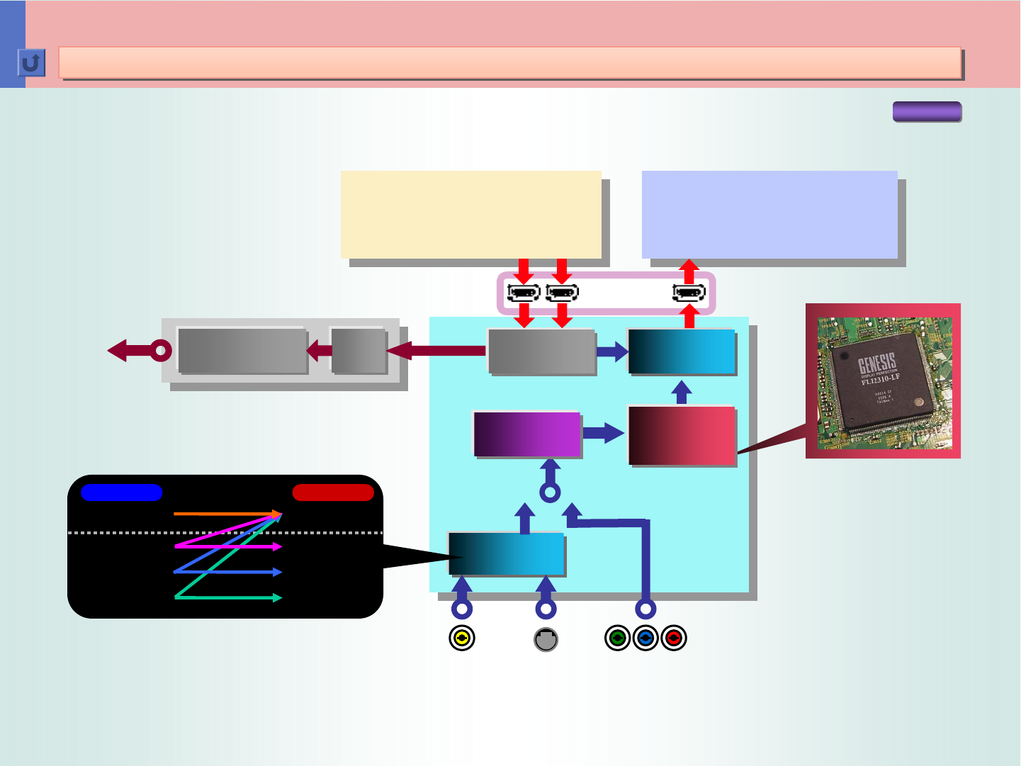
FAROUDJA
Display
HDMI
Component
Video
Video
Decoder
Decoder
TX
TX
RX
RX
480p
480i
480i/p, 720p, 1080i
480i/p, 720p, 1080i
PCM (DVD-Audio) / DD / DTS
DVD/VDR/D-VHS/STB
DVD-Audio
SPDIF
S-VideoComposite
....
....
Connection Example -- RX-D402/D401
Connection Example -- RX-D402/D401
RX-D402
DSP
DSP
Speakers
Hybrid Feedback
Hybrid Feedback
Digital Amplifier
Digital Amplifier
Component Component
HDMI HDMI
S-Video S-Video
Composite Composite
Inputs Outputs
I/P
I/P
Conversion
Conversion
A/D
A/D
Converter
Converter
*Also applies to RX-D401
< 9 >
DCDi
DCDi by FAROUDJA
by FAROUDJA
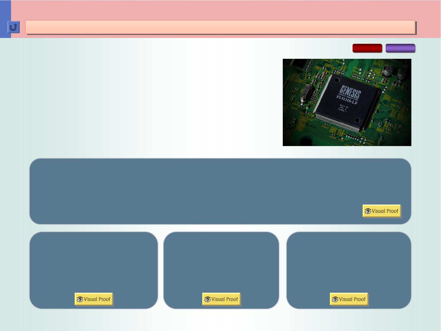
What is DCDi by FAROUDJA?
What is DCDi by FAROUDJA?
The new A/V receivers can convert video signal format to
HDMI for display on a compatible monitor, whether the
signals are from Composite, S-Video, or Component input.
In this process, the unit converts interlaced pictures to
progressive ones -- a process known as “IP conversion” --
using “DCDi by FAROUDJA”, a renowned, high-performance
device. It features a host of advanced technologies for
noise reduction and reproduction of high-definition pictures,
including:
Film Mode: Recreates the original film frames by
accurately blending the fields back together in
progressive scanning -- for images free of motion
artifacts and with full vertical resolution.
3D Cross Color
Suppression
3D Noise Reduction Fleshtone Adaptive
Noise Reduction
RX-D702 RX-D402
Video Mode: Delivers pictures from video
sources by eliminating jagged edges on
diagonal lines.
3D Deinterlacer
Filters out the noise temporally,
without smearing or ghosting of
moving objects in the image. Controls noise reduction
coefficient to deliver optimum
human flesh color.
Prevents leakage of color
information to chroma
channels.
*Also applies to RX-D401

< 10 >
DCDi
DCDi by FAROUDJA
by FAROUDJA
Effect Examples (1)
Effect Examples (1)
VISUAL PROOF
3D Deinterlacer
A unique algorithm that identifies all the moving
edges in a scene and adjusts the angle of
interpolation at each pixel so that the interpolation
always follows the edge instead of crossing it,
eliminating staircasing or jagged edge artifacts.
Smooth Diagonal Edges
Jagged Edges on
Diagonal Lines
Smooth diagonal lines are also
delivered by the 3D Deinterlacer.
Cross-Color Suppression
While composite signals are decoded,
high-frequency luma information leaks into
the chroma channel, generating noise that
looks like flashing colors or rainbow
patterns.
The Cross-Color Suppression effectively
eliminates the noise with high-performance
chroma processing.
RX-D702 RX-D402
*Also applies to RX-D401
< 11 >
DCDi
DCDi by FAROUDJA
by FAROUDJA
Effect Examples (2)
Effect Examples (2)
VISUAL PROOF
Fleshtone Adaptive Noise Reduction
Noise reduction applied on overall picture may cause
an adverse effect -- unnatural flesh color.
The Fleshtone Adaptive NR detects flesh color
contained in a picture and controls noise reduction
coefficient to deliver optimum human flesh color.
RX-D702 RX-D402
*Also applies to RX-D401
Red Cr
CbMi
Magenta
Fleshtone
CbCrdif
CbMa
CrMa
CbCrdiff
Corner Cutouts Defined by
ABS(Cb-Cr)=CbCrdiff
Definition of Fleshtone Area in Color Vector Field
Yellow
Cb
Blue
Green
Cyan

< 12 >
Transmission of Stereo Audio Signals from PC
PC Link -- USB Connection for Receiving Audio Signals from PC
Wireless USB Connection
Wireless USB Connection
USB Connection
USB Connection
2
Superior Sound Quality Matching CD/DVD
User ID Learning Function & Auto Scan
Comparison of Signal Formats
13
14
15
16
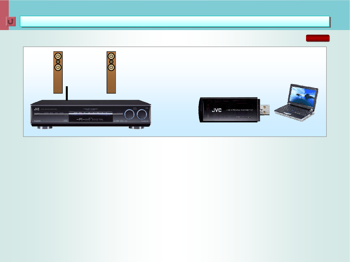
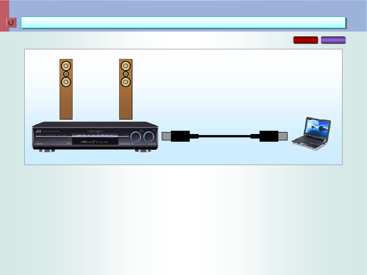
The RX-D702 permits transmission of stereo
audio signals from your PC (MP3, WMA,
Linear PCM, etc.) for listening via your audio
system. The unit even permits wireless USB
transmission, which ensures superior, near-
CD sound quality as well as enhanced
convenience.
< 13 >
(((( ))))(((( ))))
Wireless USB Connection
Wireless USB Connection
Superior Sound Quality Matching CD/DVD
Superior Sound Quality Matching CD/DVD
(1) The 2Mbps high transmission rate using the 2.4GHz band permits transmission of uncompressed
signals for lossless reproduction.
(2) Input signals are free of D/A or A/D conversion until just before output, which prevents
conversion loss.
(3) Use of DSSS (Direct Sequence Spread Spectrum) modulation technology enables transmission of
uncompressed signals with superior resistance against noise, which retains superb sound
quality.
(4) Corresponds to 16-bit, 32kHz/44.1kHz/48kHz sampling rates.
(5) Almost real-time data transmission -- delay time is only 2msecor less.
Note PC or
Desk-Top PC
USB Connection
( ( (( ( ( (
(
Max. reach is 30m,
but this depends
on the environment.
RX-D702
< 14 >
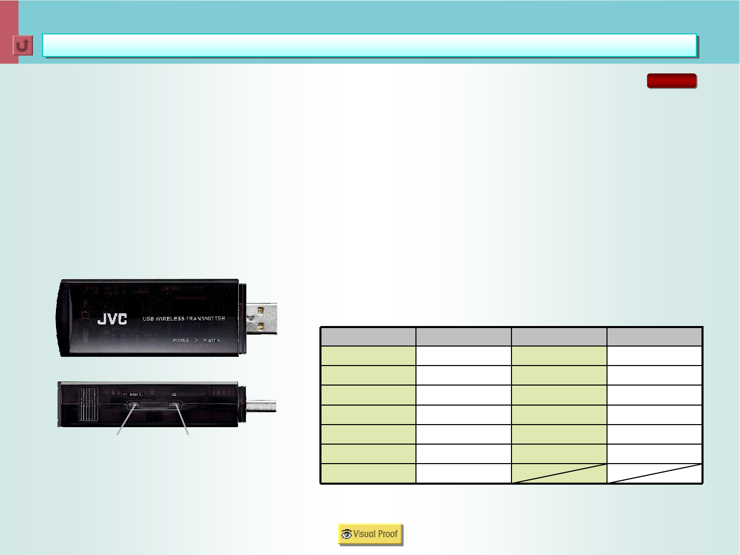
User ID Learning Function
To ensure security, the wirelss USB transmitter and
the RX-D702 share a specific “user ID”. This means
devices without the same ID cannnot receive signals
from the transmitter. And when you replace the
transmitter, “User ID Learning Function” would be
convenient. This function lets you easily set up a new
user ID, so that the unit can receive signals from the
new transmitter.
Wireless USB Connection
Wireless USB Connection
User ID Learning Function & Auto Scan
User ID Learning Function & Auto Scan
2,442 MHz7
2,472 MHz132,437 MHz6
2,467 MHz122,432 MHz5
2,462 MHz112,427 MHz4
2,457 MHz102,422 MHz3
2,452 MHz92,417 MHz2
2,447 MHz82,412 MHz1
Center FrequencyChannel No.Center FrequencyChannel No.
Transmitter
Channel Key ID Key
Auto Scan
The Wireless USB additionally features “Auto Scan”,
which stops interruption from other signals in the same
room. When the system is turned on, this function
automatically detects electric waves from other
devices -- wireless LAN, for example -- and selects a
band that won't be interrupted by the other signals.
When the signal transmission is interfered by other
waves while using the unit, simply press and hold the
“Channel Key” (on the transmitter) for a few seconds.
The transmitter automatically switches the band to a
one that won’t be interfered by the waves.
RX-D702
< 15 >
Model BModel A
EthernetEthernetWiredFeature
Wireless LAN (Optional)
PCMCIA Card Slot:
for still pictures from
digital cameras
Control with OSD:
= Movie, Music, Pictures
Wireless LAN (Optional)
Exclusive Network Only
Wireless
Wireless USB Connection
Wireless USB Connection
Comparison of Signal Formats
Comparison of Signal Formats
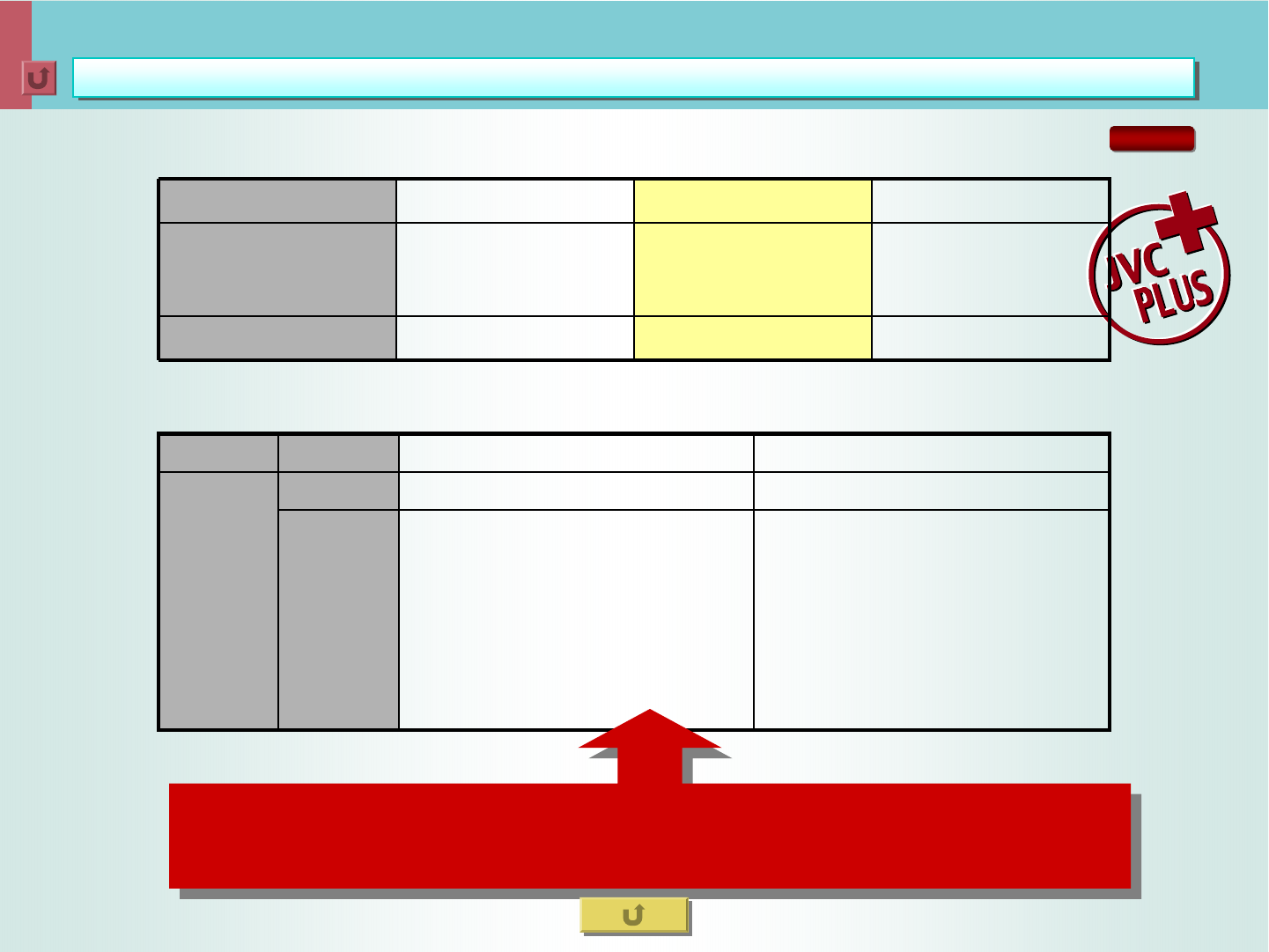
Approx. 600msecUnder 2msecApprox. 400msecDelay Time
Compression
No Compression
11Mbps
No Compression
2Mbps
Compression
(due to low data rate)
1Mbps
Format
Data Rate
Wifi/802.11bJVCBluetooth
Our Outstanding Points (Compared with Other Wireless Products)
RX-D702
JVC Advantages
ONo optional device
required.
OReceives signals
from any PC
(including Mac).
OCC Converter improves the sound
quality of compressed music files
from PC.
< 16 >
USB Connection
USB Connection
Transmission of Stereo Audio Signals from PC
Transmission of Stereo Audio Signals from PC
(1) Corresponds to 16-bit, 32kHz/44.1kHz/48kHz sampling rates for superior sound.
(2) Permits playback of any music files that can be played on the connected PC, regardless of
the software (Windows Media Player, iTunes, etc).
(3) All-digital transmission --> No D/A or A/D conversion.
Note PC or
Desk-Top PC
USB Connection
RX-D702 RX-D402
(((()
)))(((()
)))
*Also applies to RX-D401

< 17 >
CC Converter -- A JVC-Original Technology for Superior Sound
CC Converter
CC Converter
P.E.M. D.D. Converter
P.E.M. D.D. Converter
3
Background
Problems with Digital Conversion
CC Converter
Comparison of -90dB, 1kHz Sine Waves: Bit Expansion On vs. Off
D.D. Converter
Noise Shaping Response/Noise Spectrum
Problem: An analog signal of a very faint strength cannot be
accurately recreated by A/D and D/A conversion. (1)
Problem: A high-frequency analog signal cannot be accurately
recreated by A/D and D/A conversion. (2)
Bit Expansion Section
Frequency Conversion Section/Range Expansion Section
Comparison of Frequency Spectra: Range Expansion On vs. Off
CC Converter: How its workings differ from other
high-bit/upsampling systems
26
28
25
26
27
24
23
22
21
20
19
18
K2 Processing is the result of a close
collaboration among JVC studio engineers,
producers and hardware engineers,
embodying the elaborate algorithms for a
sound quality that is close to the master by
professional standards. The CC Converter is
one of its applications to improve the sound
quality of not only pure audio sources but
also compressed files, such as dts, Dolby
Digital, and MP3. The CC Converter lets you
experience a sound that is truer to the original
master than ever. With the RX-D702,
front L/R channels are processed by the CC
Converter.
192kHz/24-bit and 96kHz/24-bit A/D Converters -- RX-D702 29
192kHz/24-bit and 96kHz/24-bit A/D Converters -- RX-D402/D401 30
< 18 >
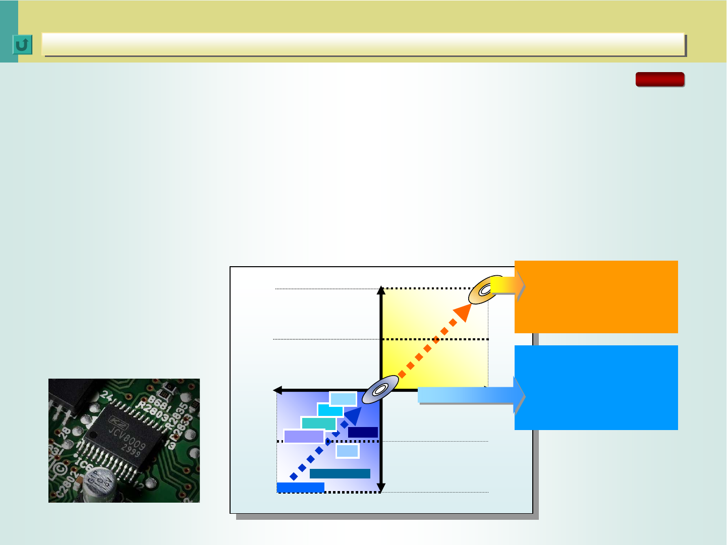
Digital audio started with
Compact Disc and has since
given birth to such super
high-fidelity formats as DVD
Audio and SACD. There’s
another trend in digital audio:
compressed data formats.
Music distribution over the
Internet, silicon audio using
compact IC cards, and digital
broadcast by satellite -- all
these formats take advantage
of audio compression
technology. This means there
are two diverging trends in
digital audio -- higher fidelity
and higher compression.
Sound Formats and Media: Quality vs. Compression
CC Converter
CC Converter
Background
Background
24-bit
176.4/192kHz
Telephone
AAC
CD
DVD Audio
MP3
MDLP
Higher
Sound Quality
Higher
Compression
20-bit
16-bit
12-bit
8-bit
8kHz 44.1kHz
DD
dts
SD
Cellular
COMPRESSION
COMPRESSION
MODE
MODE
(for MP3, WMA, etc.)
LINEAR MODE
LINEAR MODE
(for CDs, DVDs, etc.)
RX-D702
JVC is not only a hardware maker but also a software producer as well, so there
has been a close collaboration between the hardware engineers and studio
engineers for all aspects of digital sound production. “K2 Processing Technology”
is one of the many improvements developed by this collaboration to achieve
higher sound quality. It was implemented as the “Extended K2 Processing,” a
critically acclaimed application to pure audio. The CC Converter is an adaptation
of this technology for compressed music. Therefore, it improves the sound quality
of both hi-fi sources such as CD and DVD (Linear Mode) and compressed music
formats including MP3 and WMA (Compression Mode), benefiting a wide range of
digital audio contents.
< 19 >
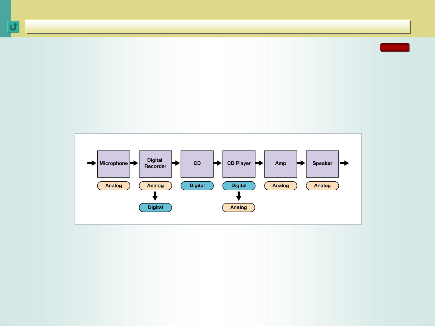
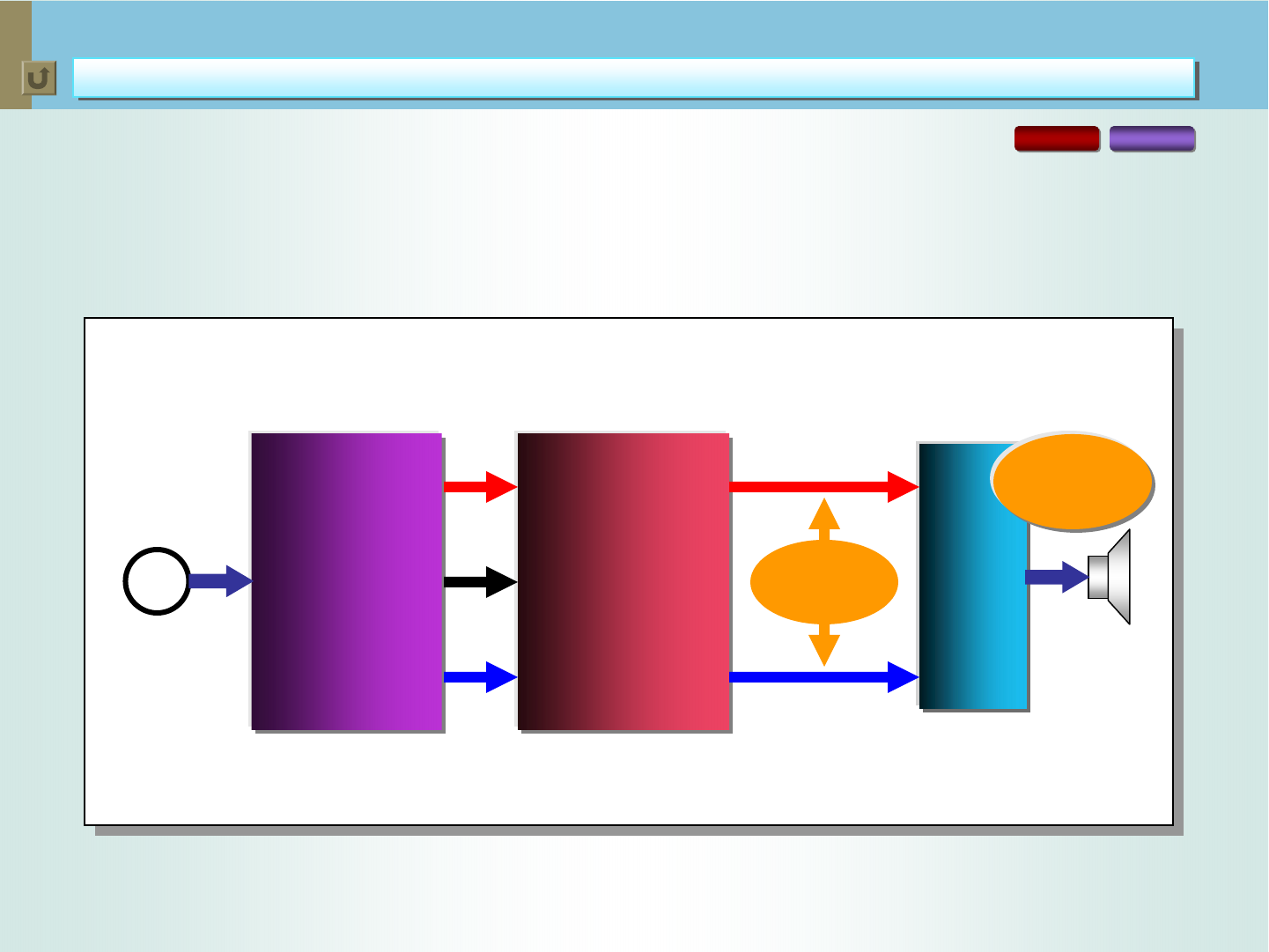
In digital audio, music is processed in digital form. The music played by musicians in a
recording studio or a concert hall is picked up by a microphone and recorded in digital form,
to be released for sale as packaged media, including CD. The consumers buy the CD to play
on a CD player: the recorded music is converted from digital to analog for playback through
an amplifier and speakers. The process of playing digital music involves analog/digital
conversion and digital/analog conversion as shown below.
Process of Playing Digital Music
The sound quality of a signal depends on the following two factors when the signal
is converted from analog to digital.
• Quantization wordlength (bits), which determines resolution or the expression of
music in the amplitude domain.
• Sampling frequency, which determines the frequency response or the expression
of music in the frequency domain.
CC Converter
CC Converter
Problems with Digital Conversion
Problems with Digital Conversion
RX-D702
< 20 >
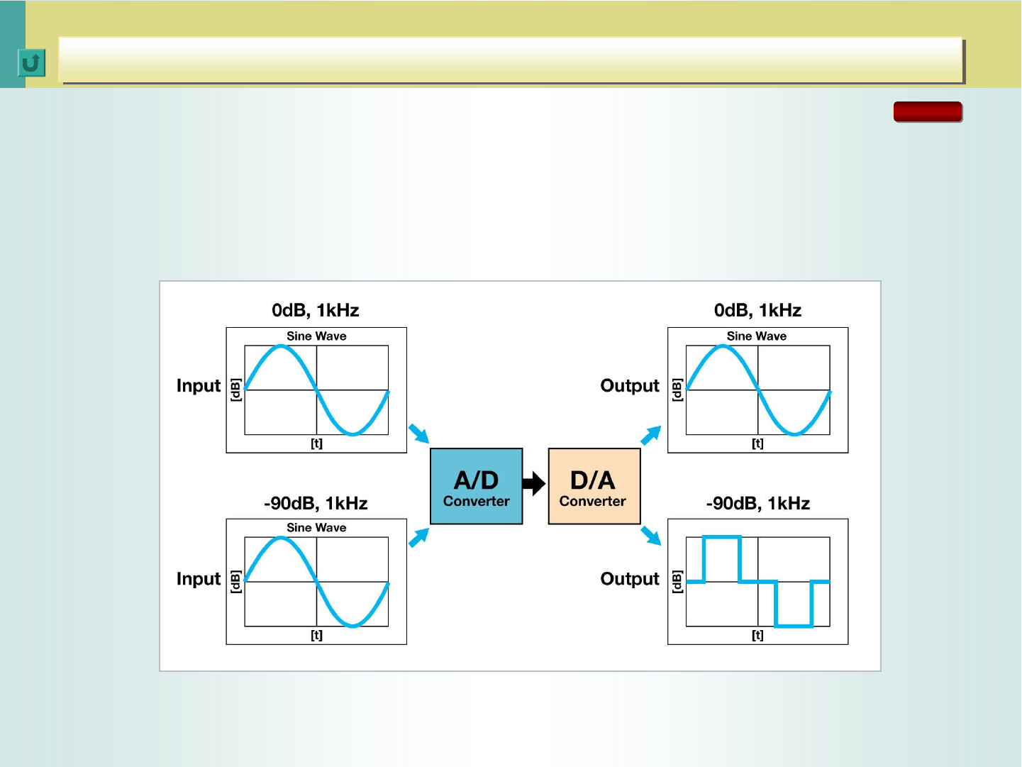
When its level is high, a 1kHz signal can produce a smooth waveform after the A/D and D/A
conversion. When the level is low, however, a stepped waveform results due to the limitation
in the resolution of a digital signal. This phenomenon occurs because digital quantization
distortion increases as the levels are reduced.
A/D and D/A Conversion in Amplitude Domain
CC Converter
CC Converter
Problem: An analog signal of a very faint strength cannot be
accurately recreated by A/D and D/A conversion. (1)
Problem: An analog signal of a very faint strength cannot be
accurately recreated by A/D and D/A conversion. (1)
RX-D702
< 21 >
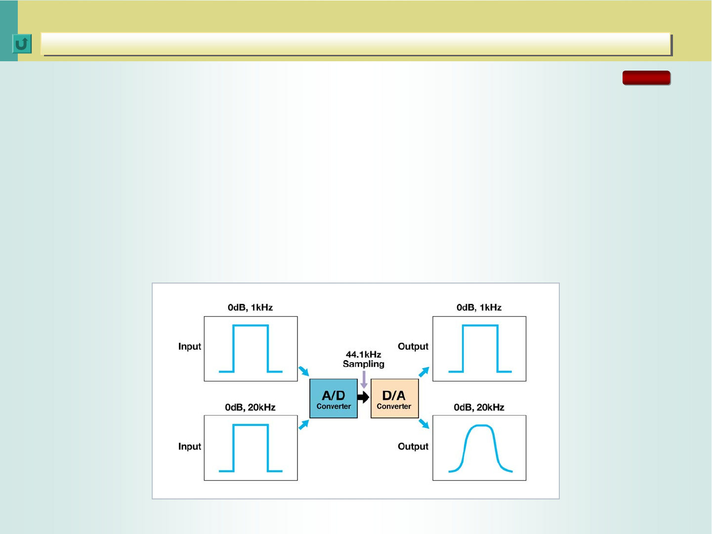
The “sampling theorem” says that, if the sampling frequency is more than twice as high as
the maximum frequency of original signal, then the original signal can be retrieved by A/D
and D/A conversion. With CDs, the sampling frequency is 44.1kHz, meaning the maximum
frequency is band-limited to 22.05kHz. Therefore, the information on the waveform for over-
22.05kHz frequencies is not transmitted.
Unless it’s sinusoidal, a signal contains multiple high-order harmonics. So does a square
wave. If the input is a 1kHz square wave signal, it retains its shape because much of the
information on the waveform for harmonics is retained after the A/D and D/A conversion.
But if the input is a square wave of a high frequency, the converted signal presents
a rounded shape because of the absence of information on high frequencies.
A/D and D/A Conversion in Frequency Domain
CC Converter
CC Converter
Problem: A high-frequency analog signal cannot be accurately recreated by A/D and D/A conversion. (2)
Problem: A high-frequency analog signal cannot be accurately recreated by A/D and D/A conversion. (2)
RX-D702
< 22 >
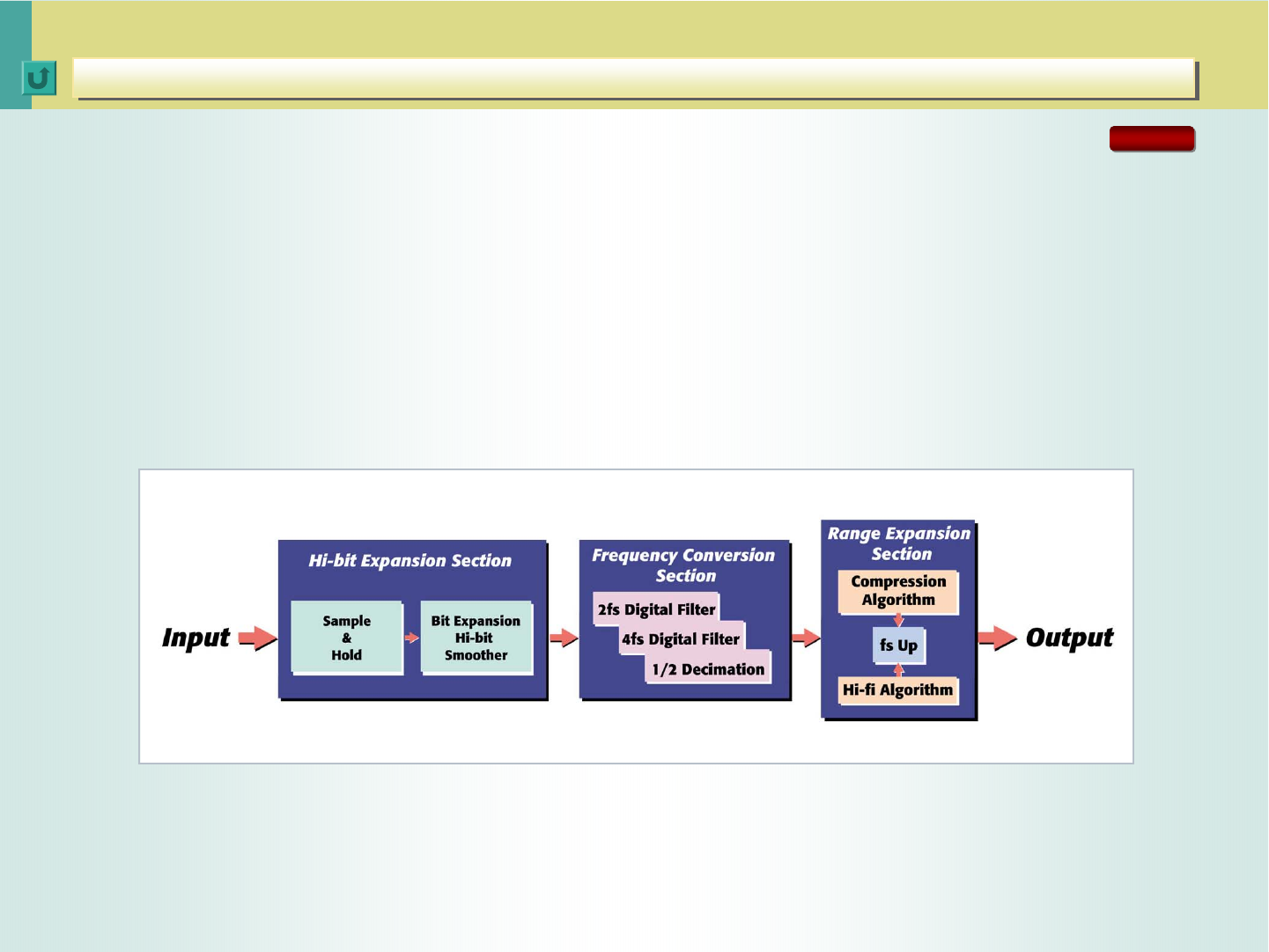
The CC Converter was developed to solve the problems with digital conversion by (1)
increasing quantization resolution for low-level signals and (2) increasing the sampling
frequency for high-frequency signals. Because bit expansion and oversampling alone do not
guarantee better sound quality, the CC Converter features JVC’s original, advanced digital
signal processing.
CC Converter Block Diagram
CC Converter
CC Converter
CC Converter
CC Converter
RX-D702
< 23 >
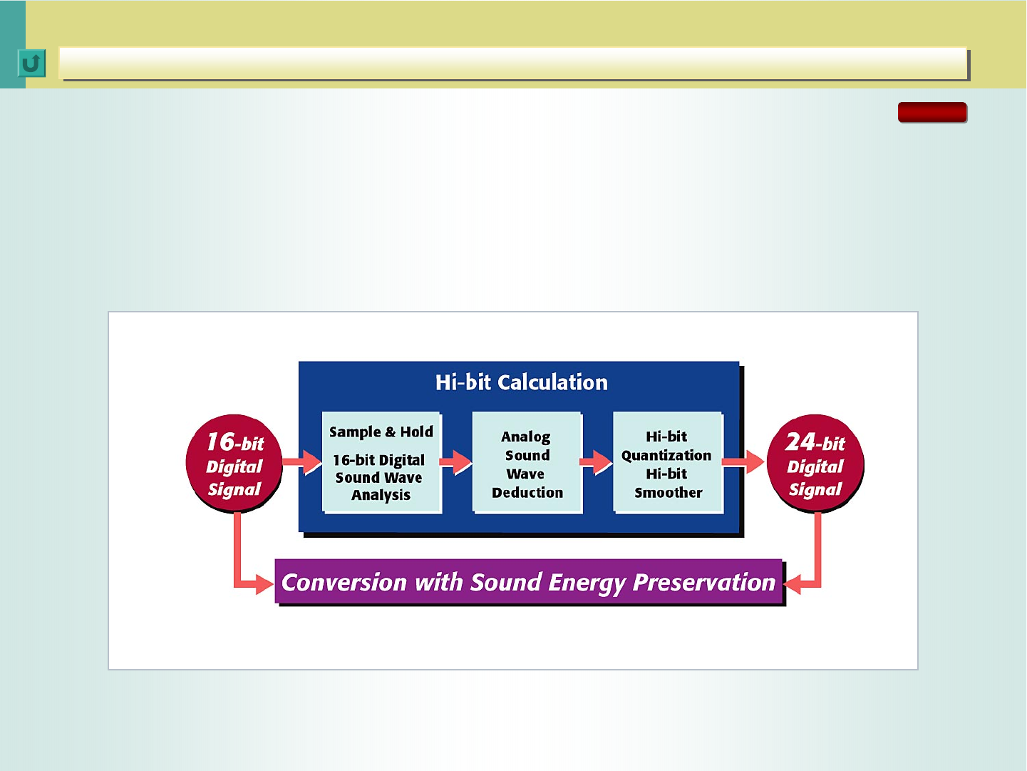
In the bit expansion section, the JVC-exclusive hi-fi processing generates a high-resolution
24-bit digital signal from a 16-bit signal. The process first analyzes the 16-bit digital signal to
deduce the original analog signal before A/D conversion, and then applies hi-bit expansion to
smooth the signal waveform. What’s more, the process ensures that the 24-bit signal
preserves the same sound energy of the 16-bit digital signal.
Hi-bit Expansion Processing
CC Converter
CC Converter
Bit Expansion Section
Bit Expansion Section
RX-D702
< 24 >
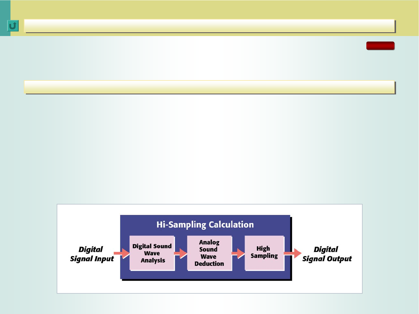
The frequency conversion section doubles or quadruples the sampling frequency for playback
of high-frequency signals that a following stage generates.
The range expansion section applies the JVC-exclusive range expansion processing to
compensate for the conversion distortion that occurs when the analog signal is converted into
a digital signal.
The human ear, it is said, cannot hear frequencies above 20kHz, but removing frequencies
higher than 20kHz changes the waveform of audible frequencies, resulting in a signal that
sounds different from the original. The range expansion section overcomes this problem by
deducing the original waveform of a signal before A/D and D/A conversion and modifying the
signal’s waveform accordingly. For playback of frequencies above 20kHz generated by this
waveform processing, the range expansion section has a frequency conversion section
preceding it.
Range Expansion Block Diagram
Range Expansion Section
Range Expansion Section
CC Converter
CC Converter
Frequency Conversion Section
Frequency Conversion Section
RX-D702

< 25 >
There are several high-bit/upsampling processing
systems on the market that claim to offer the same
benefits as the CC Converter. They are all designed to
create and add frequencies (harmonics) over 20kHz
deriving from an input signal.
But we do not believe the mechanical addition of
harmonics can ensure the faithful recreation of
“musicality.” The sound generated by an instrument
contains harmonic components. And it is the harmonic
components that determine the tone of an instrument.
The harmonic components of one violin are different
than those of another. One player’s phrasing produces
different harmonic components from one by others.
Some instruments feature rich resonance, while others
produce hardly any.
CC Converter
Accurate D/A conversion and reproduction of the recreated
data requires a process to expand the frequency range of the
analog signals. The frequency-range expansion of the analog
signals to beyond 20kHz results in improved music data for
the audible range. The CC Converter expands CD’s frequency
range fourfold to 88.2kHz using 176.4kHz (44.1kHz x 4)
sampling frequency. With DVD-Video, the frequency range is
expanded to 96kHz, while the sampling frequency is 192kHz
(48kHz x 4).
Therefore, applying the same process for adding
harmonic components is not proper in view of
“musicality.” Reviewers of European audio magazines
are highly critical of this approach. Moreover, the existing
high-bit/upsampling processing systems use 2x sampling
frequencies -- 88.2kHz for CDs to achieve a 44.1kHz
frequency range, or 96kHz for DVD Video to achieve a
48kHz frequency range.
JVC’s CC Converter does not simply create and add harmonic
components. It computes the data that was lost during the D/A
conversion by taking advantage of JVC’s exclusive algorithms.
This means the CC Converter has the processing power to
recreate the original signal that should have been recorded --
based on the digital signals for the audible range recorded on
a CD.
CC Converter
CC Converter
CC Converter: How its workings differ from other high-bit/upsampling systems
CC Converter: How its workings differ from other high-bit/upsampling systems
RX-D702

< 26 >
The figure shows the actual measured
waveform of a bit-expanded -90dB
sinusoidal signal.
-90dB, 1kHz Sine Wave: Bit Expansion Off
The figure shows the frequency spectra of a music signal with the range expansion on
and off. With the expansion off, the level is sharply reduced beyond 22kHz. But with
the expansion on, the level is naturally extended beyond 22kHz and higher.
-90dB, 1kHz Sine Wave: Bit Expansion On
Expansion ON
Expansion OFF
Level (dB)
Frequency (kHz)
VISUAL PROOF
CC Converter
CC Converter
Comparison of -90dB, 1kHz Sine Waves: Bit Expansion On vs. Off
Comparison of -90dB, 1kHz Sine Waves: Bit Expansion On vs. Off
Comparison of Frequency Spectra: Range Expansion On vs. Off
Comparison of Frequency Spectra: Range Expansion On vs. Off
CC Converter
ON
CC Converter
OFF
Frequency (Hz)
COMPRESSION MODE
COMPRESSION MODE (for MP3, WMA, etc.)
LINEAR MODE
LINEAR MODE (for CDs, DVDs, etc.)
Level
RX-D702
RX-D702
< 27 >
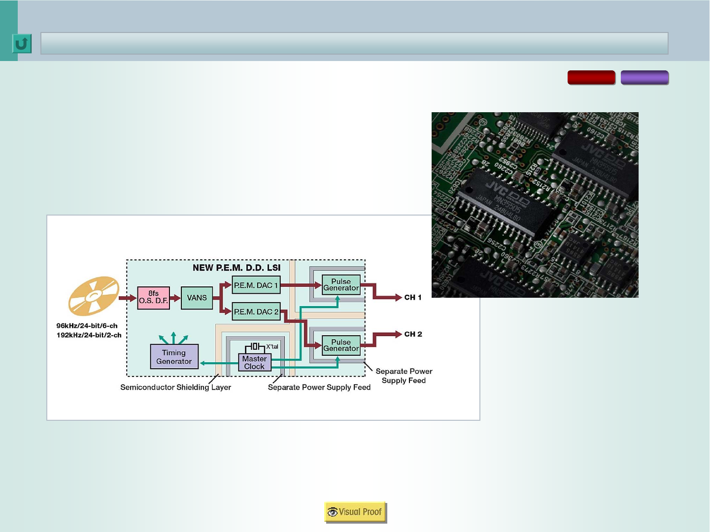
P.E.M. D.D. Converter
P.E.M. D.D. Converter
D.D. Converter
RX-D702 RX-D402
The JVC exclusive D/A converter turns the
192kHz/24-bit output into an analog signal
with impeccable accuracy.
*Also applies to RX-D401

< 28 >
P.E.M. D.D. Converter
P.E.M. D.D. Converter
Noise Shaping Response/Noise Spectrum
Conventional D/A Converter
Noise Shaping Response (Theoretical) Noise Spectrum
P.E.M. D.D. Converter
VANS=JVC Advanced Noise Shaper
Response (dB)
Frequency (Hz)
Response (dB)
Frequency (Hz)
VISUAL PROOF
RX-D702 RX-D402
*Also applies to RX-D401

< 29 >
P.E.M. D.D. Converter
P.E.M. D.D. Converter
192kHz/24-bit and 96kHz/24-bit A/D Converters -- RX-D702
VISUAL PROOF
RX-D702
P.E.M. D.D.
P.E.M. D.D.
Converter
Converter
A/D
A/D
Converter
Converter
DSP
DSP
Aureus
Aureus™
™
TMS320DA601
TMS320DA601
Dolby Digital/
Dolby Digital/PLIIx
PLIIx/DTS
/DTS
DAP/3D
DAP/3D-
-H/GEQ/
H/GEQ/
DRC/BM
DRC/BM
DIT
DIT
DIR
DIR
Digital IN
Digital IN
Analog IN
Analog IN
L/R
L/R
HDMI
HDMI
L/R
L/R
Ls/
Ls/Rs
Rs
C/LFE
C/LFE
SurrBackL
SurrBackL/R
/R
Digital Out
Digital Out
HDMI
HDMI
USB
USB
Wireless
Wireless
USB
USB
Opti
Opti 2
2
Opti
Opti 1
1
Coax
Coax
DVD Audio IN
CC
CC
Converter
Converter
Opti
Opti 3
3
P.E.M. D.D.
P.E.M. D.D.
Converter
Converter
P.E.M. D.D.
P.E.M. D.D.
Converter
Converter
D/A
D/A
Converter
Converter

< 30 >
P.E.M. D.D. Converter
P.E.M. D.D. Converter
192kHz/24-bit and 96kHz/24-bit A/D Converters -- RX-D402/D401
VISUAL PROOF
P.E.M. D.D.
P.E.M. D.D.
Converter
Converter
P.E.M. D.D.
P.E.M. D.D.
Converter
Converter
P.E.M. D.D.
P.E.M. D.D.
Converter
Converter
D/A
D/A
Converter
Converter
A/D
A/D
Converter
Converter
DSP
DSP
Aureus
Aureus™
™
TMS320DA601
TMS320DA601
Dolby Digital/
Dolby Digital/PLIIx
PLIIx/DTS
/DTS
DAP/3D
DAP/3D-
-H/GEQ/
H/GEQ/
DRC/BM
DRC/BM
DIT
DIT
DIR
DIR
Digital IN
Digital IN
Analog IN
IN
L/R
L/R
HDMI
HDMI
L/R
L/R
Ls/
Ls/Rs
Rs
C/LFE
C/LFE
SurrBack
SurrBack
L/R
L/R
Digital Out
Digital Out
HDMI
HDMI
USB
USB
Opti
Opti 2
2
Opti
Opti 1
1
Coax
Coax DVD Audio IN
RX-D402
*Also applies to RX-D401

< 31 >
Aureus™ -- High-Performance DSP for Superior Sound Quality
JVC exclusive DSP
JVC exclusive DSP
4
Texas Instruments Floating-Point DSP -- Aureus™ (TMS320DA601)
JVC’s DSP
Sound Field Analysis (Ray Tracing)
JVC exclusive DSP -- implemented by the
Texas Instruments “Aureus”™ DSP --
simulates the acoustics of music venues.
In doing so, it makes use of a vast amount of
DSP-computed data for the creation of sound
field patterns that conventional processing
systems, based on field-measured impulse
responses, have difficulties recreating.
With JVC’s DSP, the sound fields are
reproduced most naturally, with early
reflections simulated realistically. More than
ten years ago, JVC sent engineers worldwide
to measure the acoustics of famous theaters
and concert halls. JVC exclusive DSP
embodies both the old know-how and latest
technologies to make you feel you are there.
The reason why sound field simulation by DSP produces better
results than one based on actual measured environments.
DAP Modes (1)
5-Band Graphic Equalization
36
32
33
34
35
38
3D Headphone
Midnight Mode
Center-Channel Alignment
Smart Surround Setup
39
40
41
42
DAP Modes (2) 37
< 32 >
Features
• 1,800MIPS* or 1,350MFLOPS** (at 225MHz clock speed) -- one of the
highest processing power ratings on the market
• 32-bit (64-bit double precision) accurate operations
• Decode formats: Dolby Digital, Dolby Digital EX, Dolby Pro Logic IIx,
DTS, DTS-ES, DTS 96/24, DTS NEO:6
• Functions: DAP, 3D-PHONIC, 3D Headphone, DSP Digital Equalizer,
Dynamic Range Control, Bass Management
Advantages
• A single chip performing DTS 96/24 processing
and DAP (Digital Acoustics Processing) with
power to spare
• More accurate implementation of simulated DAP
sound fields
• Compact size conducive to reduction in digital
noise
• Floating-point operations for more accurate
calculations with an expanded range of numbers
* FLOPS (Floating Point Operations per Second): the number of floating-point calculations per second performed with real numbers.
** MIPS (Million Instructions per Second): A 1MIPS computer processes 1 million instructions per second. An “instruction” is a command
sent out to a DSP to directly control and operate it. A DSP executes instructions stored in memory, makes calculations and outputs the
result. The number represents a DSP or CPU’s capability of computing -- the greater the power of processing.
JVC exclusive DSP
JVC exclusive DSP
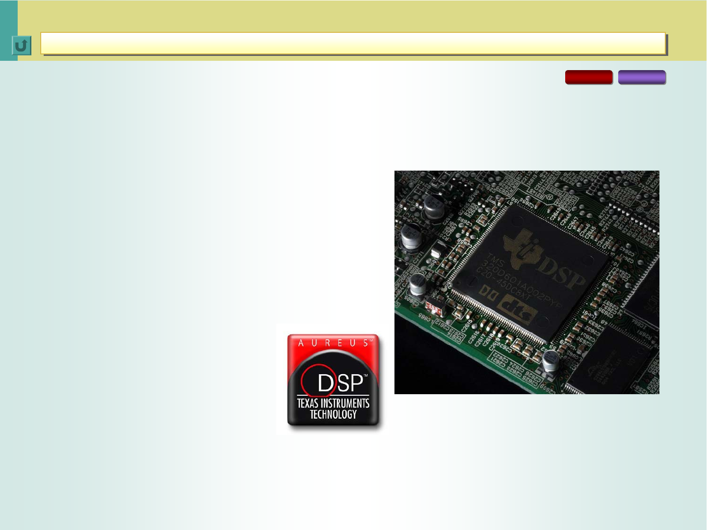
Texas Instruments Floating-Point DSP -- Aureus™ (TMS320DA601)
Texas Instruments Floating-Point DSP -- Aureus™ (TMS320DA601)
At the heart of the RX-D702/D402/D401’s DSP is a new high-performance Texas Instruments
DSP -- Aureus™. It’s the world’s fastest, highest-performing chip of its kind now, replacing two
conventional DSP chips. The JVC receiver is the world’s first to feature this LSI.
RX-D702 RX-D402
*Also applies to RX-D401

< 33 >
Listening to the 7.1-channel surround as processed by the
JVC DAP (Digital Acoustics Processor) evokes a totally
different surround sound experience from what you get
from stereo or 5.1-channel sound. Listen carefully to the
5.1-channel sound of a DVD in its recorded form and
you’ll notice it does not produce the sensation of being
surrounded by sound.
JVC developed the DAP for one objective: to make the
home theater audience feel as if they were in the best
movie theater surrounded by an array of speakers to the
left and right, and behind. Then they would feel enveloped
in sound, with a helicopter, for instance, moving left to
right, or front to back.
JVC exclusive DSP, as implemented by the TI Aureus™
chip -- embodies the algorithms of sound field recreation
that are developed specifically for advanced home theater
receivers. The sound field patterns are created on the
basis of the computer sound field simulation technology
developed by a leading concert hall construction company.
Patterns of reflections are calculated based on the data of
the sound fields of the concert halls, theaters and movie
theaters.
*To verify simulated halls, the contractor creates a precision scaled-down
miniature hall using the same materials for walls, seats, etc., in the same
shape. A second larger scaled-down model will then be made to further
refine the data.
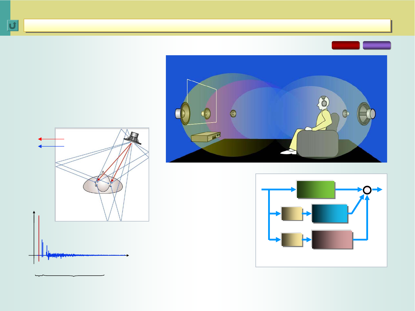
5.1-channel Playback
Stereo Playback
7-Channel DAP Playback
JVC exclusive DSP
JVC exclusive DSP
JVC’s DSP
JVC’s DSP
RX-D702 RX-D402
*Also applies to RX-D401
< 34 >
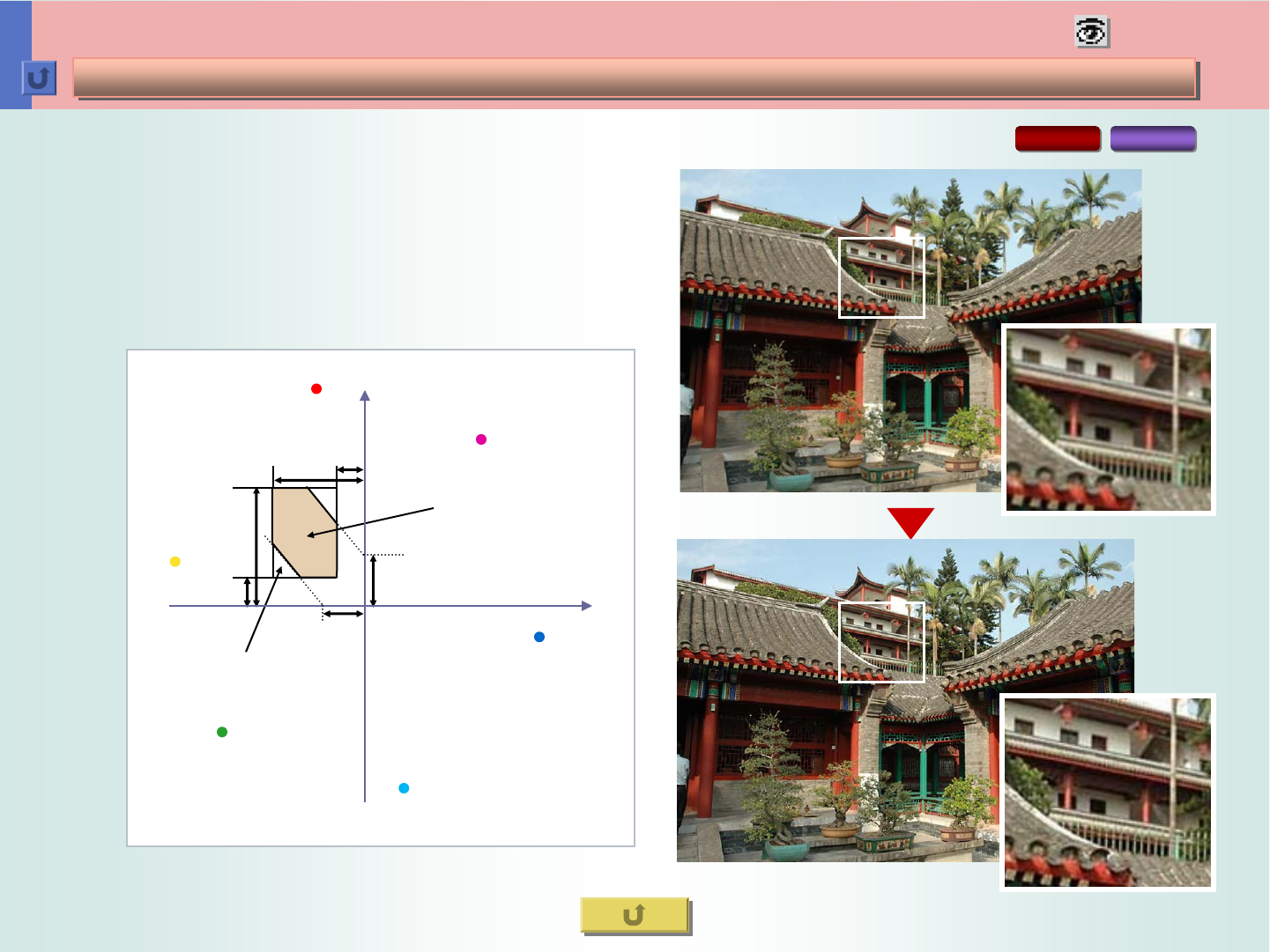
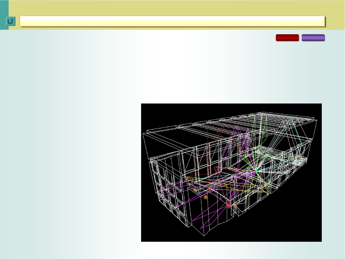
The figure shows the paths of the “sound rays” as they propagate from a sound
source (red, black and brown balls) to the receiver (blue ball). The DSP
calculates the properties of a reflection sound (time delay and direction) from the
paths of the sound rays. The simulation computations it does for 7.1-channel
surround are different from those for 5.1-channel surround or for stereo.
This means the DSP does optimal simulation computations according to the
configuration of speaker setting.
Blue ball: receiver’s position (seating
position)
Brown ball up front: sound source (stereo
2-channel)
3 red balls up front: sound source (left,
right and center channels)
2 red balls in the rear: sound source
(surround left and right channels) (5.1-
channel surround consists of five red balls.)
4 green balls to the sides and in the rear:
7.1-channel surround consists of three red
balls and four black balls.
Rear
Front
JVC exclusive DSP
JVC exclusive DSP
Sound Field Analysis (Ray Tracing)
Sound Field Analysis (Ray Tracing)
RX-D702 RX-D402
*Also applies to RX-D401

< 35 >
To recreate an environment’s sound field, a real hall or
cinema’s sound field is measured for data. For
measurements, a pulse noise is emitted, its direct and
indirect sounds are picked up by microphones, and their
data is recorded. This is the approach adopted by other
home theater receiver/processor manufacturers.
But measuring the sound field of an existing environment
entails inaccuracies in the methodology. For instance,
microphones have different characteristics, from model to
model and from unit to unit. The measured data gives
clues to time and level of a sound, but not to the direction.
Measurements are made only at selected spots. Softest
sounds are not captured accurately.
Impulse Response
Time Series Analysis of
Simulated Hall Acoustics
Sound field simulation by DSP, on the other hand, can
produce accurate data by supplying parameters, such as
the shape of a hall, the shape and acoustic properties of
interior materials, and the presence/absence of an
audience. Because this data is not based on actual
measurements that could be affected by the measuring
equipment used or its inaccuracy, it allows the accurate
recreation of the frequency response and even the
direction of each reflection.
Direct Sound
Early Reflections
Reverberations
Level
Time
JVC exclusive DSP
JVC exclusive DSP
The reason why sound field simulation by DSP produces better results than
one based on actual measured environments.
The reason why sound field simulation by DSP produces better results than
one based on actual measured environments.
RX-D702 RX-D402
*Also applies to RX-D401
< 36 >
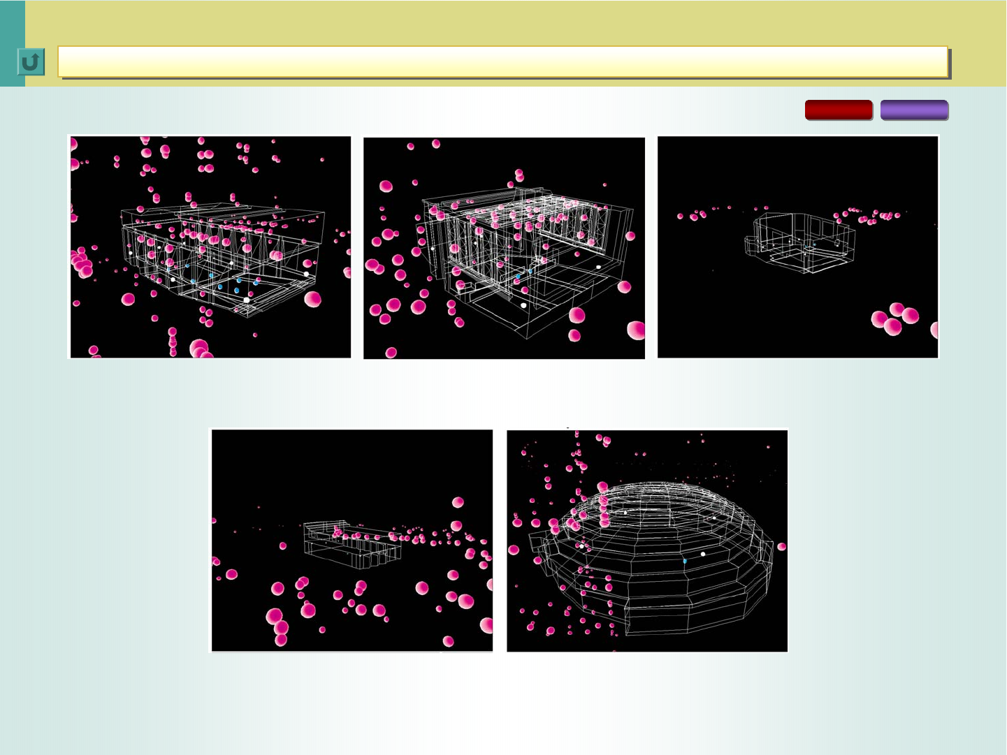
THEATER 1
Capacity: 6,500m3Seats: Approx. 600
Reverberation: 1.23 sec.
THEATER 2
Capacity: 2,000m3Seats: Approx. 300
Reverberation: 0.55 sec.
LIVE CLUB
Capacity: 400m3Seats: 70
Reverberation: 0.35 sec.
DANCE CLUB
Capacity: 2,200m3Seats: 240
Reverberation: 0.55 sec.
PAVILION
Capacity: 549,700m3
Reverberation: 5.22 sec.
JVC exclusive DSP
JVC exclusive DSP
DAP Modes (1)
DAP Modes (1)
RX-D702 RX-D402
*Also applies to RX-D401
< 37 >
*When the SURR. BACK SPK. setting is “ON”, the DAP performs 7-channel processing,
outputting reverberation components to Surround Back channels.
JVC exclusive DSP
JVC exclusive DSP
DAP Modes (2)
DAP Modes (2)
---
O*
-
O*
THEATER 2
OOOOOO
All Ch. Stereo
OOOOOO
3D Phonic
OOOOOO
3D Headphone
O*O*O*
-
O*
-MONO FILM
O*O*O*
-
O*
-PAVILION
O*O*O*
-
O*
-DANCE CLUB
O*O*O*
-
O*
-LIVE CLUB
O*O*O*
-
O*
-HALL 2
O*O*O*
-
O*
-HALL 1
DAP
O*O*O*
-
O*
-THEATER 2
O*O*O*
-
O*
-THEATER 1
Pro Logic II
Movie+DAP
---
O*
-
O*
THEATER 1
---
O*
-
O*
PAVILION
---
O*
-
O*
DANCE CLUB
---
O*
-
O*
LIVE CLUB
---
O*
-
O*
HALL 2
---
O*
-
O*
HALL 1
Multi-Channel DAP
PCM2 ch5.1 ch2 ch5.1 ch
Mode Signal AnalogLinearDolby DigitalDTS
For 3D-like reproduction of classic movies with mono soundtracksMONO FILM
Small movie theaterTHEATER 2
Large movie theaterTHEATER 1
Exhibition hall with a high ceilingPAVILION
Rocking dance clubDANCE CLUB
Live music club with a low ceilingLIVE CLUB
Large vineyard-shaped hall designed primarily for classical concertsHALL 2
Large shoebox-shaped hall designed primarily for classical concertsHALL 1
For Recreation of Spatial Feel of :Mode
RX-D702 RX-D402
DAP Modes for
RX-D702/D402/D401
*Also applies to RX-D401

< 38 >
JVC exclusive DSP
JVC exclusive DSP
5-Band Graphic Equalization
5-Band Graphic Equalization
Frequency (Hz)
Response (dB)
Response (dB)
Frequency (Hz)
250
63
16k
4k
1k
Center Frequency (Hz)
RX-D702 RX-D402
A graphic equalizer lets you adjust the levels of
center frequencies.
An analog equalization circuit is built from resistors and
capacitors, therefore noise and phase reversal are
inevitable. A digital equalization circuit performs its
function in the entirely digital domain. Clarity and
consistent definition are its advantages.
The TI Aureus™ chip ensures high-speed processing
for equalization, while it executes various decode
processing (Dolby Digital, dts, etc.)
Center Frequencies: 63Hz, 250Hz,
1kHz, 4kHz, 16kHz
Level: ±8dB, 2dB steps
1 manual EQ setting for each source
100101102103104105
0
102103104
4
8
-4
-8
0
5
10
-5
-10
*Also applies to RX-D401
< 39 >
JVC exclusive DSP
JVC exclusive DSP
3D Headphone
3D Headphone
In a typical listening room, sound from
speakers you perceive consists of three
elements: direct sound, early reflections
(echoes from walls/ceiling/floor), and
reverberation. These elements let you
locate the sound source and recognize
its size. This is called Head Related
Transfer Function (HRTF).
Direct Sound
Reflections Reverberations
In developing the 3D
Headphone technology,
JVC has applied an
exclusive algorithm that
divides the audio signals
into the same three
elements and conducts
processing individually
(convolution processing).
This ensures that sound
from headphones has the
same realism, dynamism,
and localization as that from
multi-channel speakers.
Direct Sound
Reflections
RX-D702 RX-D402
Delay
Delay
Direct Sound
Direct Sound
Processing
Processing
Early
Early
Reflection
Reflection
Processing
Processing
Delay
Delay Reverberation
Reverberation
Processing
Processing
+
+
IN
IN OUT
OUT
Block Diagram of Convolution Processing
Sound Frequencies Detected in
a Typical Listening Room
Virtual Sound Field Created by
the 3D Headphone Technology
*Also applies to RX-D401
< 40 >
JVC exclusive DSP
JVC exclusive DSP
Midnight Mode
Midnight Mode
The DSP divides input signals into three bands (LOW/MID/HIGH),
and processes the signals so that low-level sound in each band will
get louder and loud sound will be moderated. This makes the output
sound clear across the range, regardless of the original levels.
In addition, the unit individually controls the sound compression level
of each band. When the sound level is low, the compression levels of
high and low frequencies are raised to deliver enough loudness.
When the sound level is high, the gains of the two frequencies are
moderated to prevent excessive bass and treble output.
These technologies combine to retain the excitement of multi-channel
sound and keep dialog sound clear even at low sound levels.
The technologies are applied even when the sound level is lowered
suddenly, which is especially useful for midnight viewing, for example.
RX-D702 RX-D402
Frequencies of Input/Output Audio Signals
Frequency of Output Signals
Frequency
Level
Low Mid High
OUTPUT
Midnight Mode
Processing
Frequency
Level
High Sound Levels
Low Sound Levels
Frequency
Level
INPUT
Low Mid High
*Also applies to RX-D401

< 41 >
JVC exclusive DSP
JVC exclusive DSP
Center-Channel Alignment
Center-Channel Alignment
The center speaker is usually placed on top of or under the display, while
the front speakers are set at or near ear level. The result is that dialog,
carried by the center speaker, seems out of place relative to music and
sound effects. JVC's exclusive DSP application virtually positions the
center speaker to align it with other speakers with respect to height.
The dialog simply sounds more natural.
RX-D702 RX-D402
Virtual Repositioning of the Center Speaker with Center Channel Alignment
*Also applies to RX-D401

< 42 >
JVC exclusive DSP
JVC exclusive DSP
Smart Surround Setup
Smart Surround Setup
Setting up a home theater can be time-consuming and even confusing. Normally, you have to check which
speaker channels (front, center, surround, and surround back) you have installed, the distance of each
speaker from the listening position, and the level of each speaker.
But with JVC's Smart Surround Setup Version 3.0, it takes just seconds to set up the acoustic environment
of your home theater. Clap your hands, and the delay times of all channels are set individually, and the
level of each speaker is automatically trimmed -- optimized for your listening position. You can even fine-
tune the settings if you prefer. Setup information is displayed on-screen for easy confirmation.
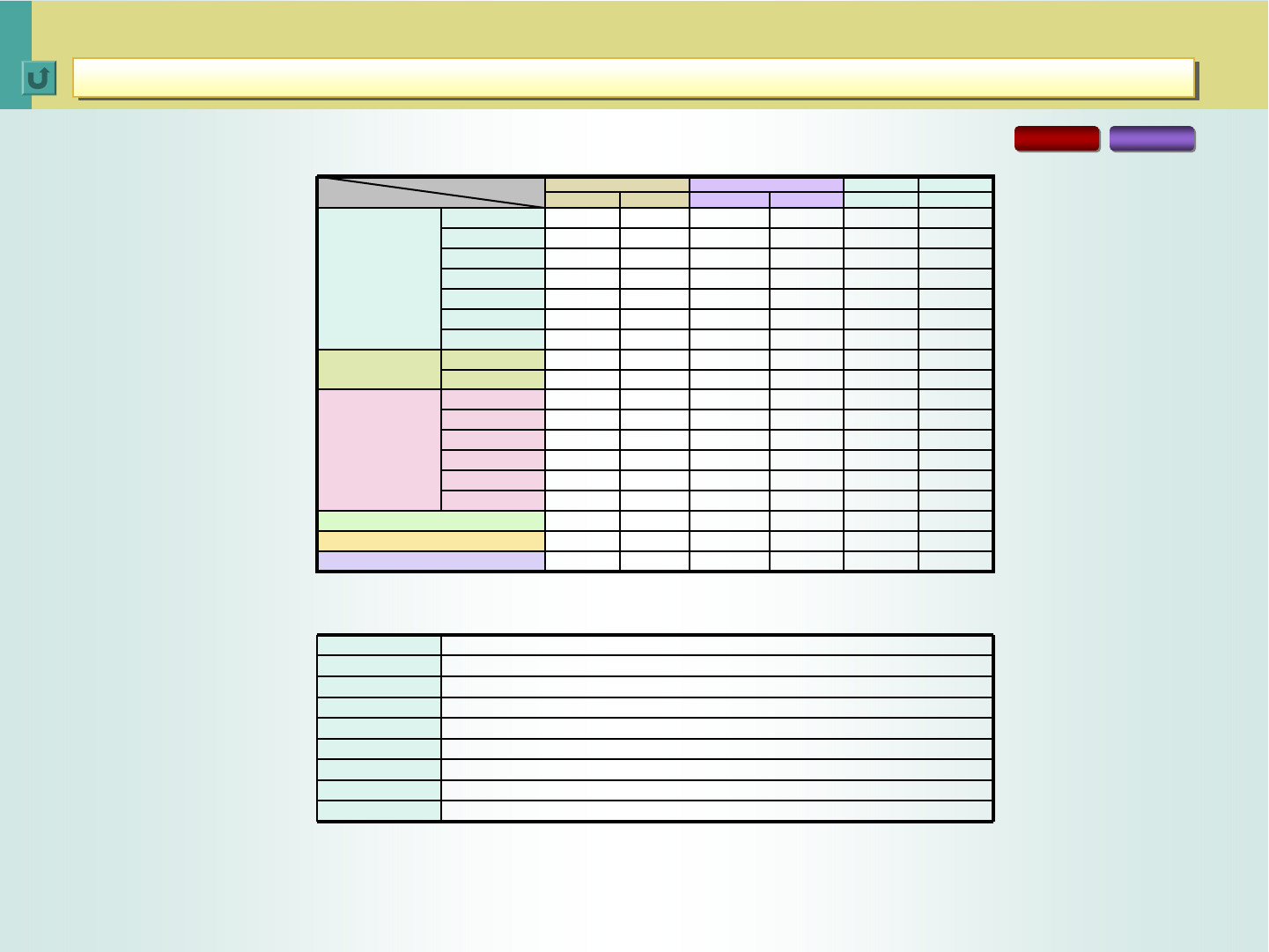
RX-D702

< 43 >
Hybrid Feedback Digital Amplifier
Hybrid Feedback Digital Amplifier
Hybrid Feedback Digital Amplifier
5
Background -- What is PWM?
Evolution of Hybrid Feedback Digital Amplifier (1)
JVC-exclusive Hybrid Feedback Digital Amplifier
enables a lot more than the compact dimensions
of the A/V receivers. Featuring dual analog
feedback and digital feedback circuits, this
device significantly “brushes up” the input signals,
which ensures significantly lowered total
harmonic distortion -- to 0.004% -- and superior
speaker driveability. The result is high-quality
sound matching that from a high-grade analog
amp.
The RX-D702 and RX-D402/D401 come with an
upgraded “Ver. III” device, which incorporates a
wide range of technological improvements for
even better sound quality.
Problems of Digital Amplifiers
44
45
56
Hybrid Feedback Digital Amplifier
Hybrid Feedback Digital Amplifier Ver
Ver. III
. III --
--
Technological Improvement for Even
Technological Improvement for Even
Better Sound
Better Sound
Low-Voltage Power Supply
One-Chip Solution with JCV8015
JCV8015 Benefits (2) -- PWM Modulator/External Clock
JCV8015 Benefits (1) -- Operational Amp
49
50
51
52
JCV8015 Benefits (3) -- ±2.5V Regulator
Quality Parts for Superior Sound Reproduction
53
54
Comparison of Speaker Driveability
T.H.D. Comparison of Digital Amplifiers
55
56
Evolution of Hybrid Feedback Digital Amplifier (2) 47
Evolution of Hybrid Feedback Digital Amplifier (3) 48

< 44 >
JVC technologies for satisfying the THX Ultra2 certification
Hybrid Feedback Digital Amplifier
Hybrid Feedback Digital Amplifier
Background -- What is PWM?
Background -- What is PWM?
ON +1
-1
0
+1
OFF
-1
ON
OFF
PWM (Pulse Width Modulation)
RX-D702 RX-D402
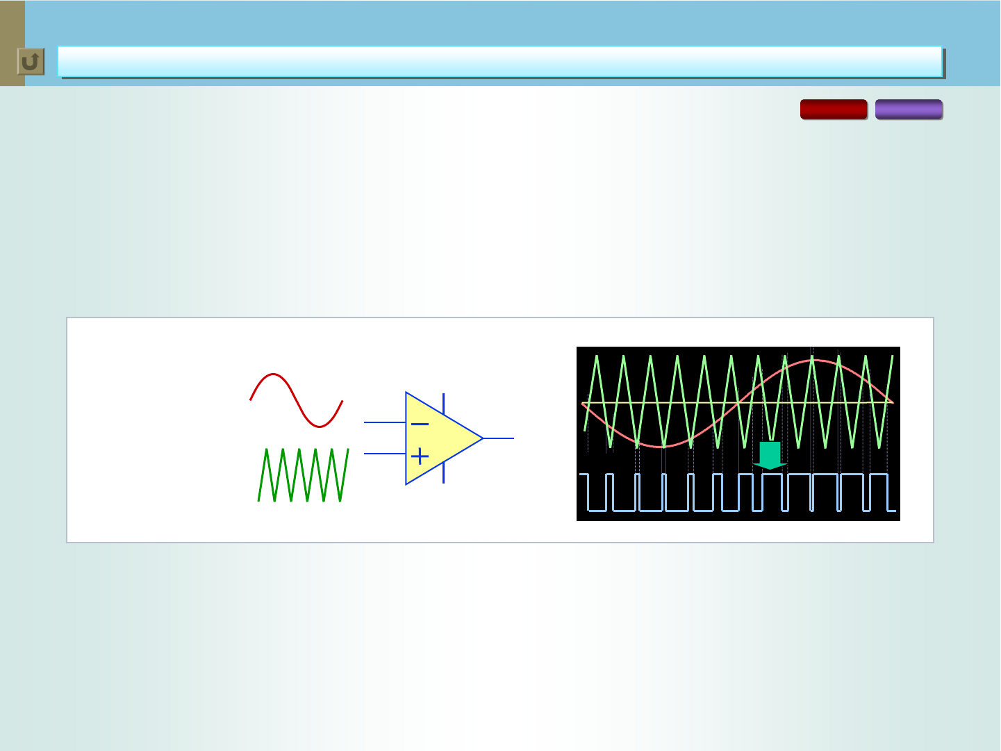
Pulse Width Modulation (PWM) is a method of digitally encoding analog
signal levels. In the process, continuously varying value of input audio
signals is detected based on the reference voltage (Vref) by comparing
the signals with triangular waves. When the value is higher than Vref
level, the pulse is switched “ON”, and when it gets below Vref, it’s turned
“OFF”. The higher than Vref the value is, the longer the pulse is kept
“ON”. The lower than Vref the value is, the longer the pulse is left “OFF”.
Thus, square-shaped waves are generated, representing either “ON” or
“OFF” state of the pulse -- length of the “ON” and “OFF” pulses
expresses the value of audio signals with respect to the Vref levels.
These waves are called “PWM signals”. Precision of the PWM signals is
one of the elements that determine the sound quality delivered by a
digital amplifier. This is why “feedback” process is essential for delivering
high-quality sound.
Switching Power Supply with
Highly-Efficient Operations
OFF ON
Power MOS FET
Switch
●Heat Generation
1. Loss from ON Impedance
2. Switching Loss
PWM
Generation of PWM Signals
1. Values of input audio signals are detected by
comparison with triangular waves.
2. High-precision triangular waves are necessary.
Comparator
Input Audio
Signals
Triangular
Waves
*Also applies to RX-D401

< 45 >
Analog
Digital ●PCM-PWM
●Analog-PWM
PWM
JVC technologies for satisfying the THX Ultra2 certification
Hybrid Feedback Digital Amplifier
Hybrid Feedback Digital Amplifier
Problems of Digital Amplifiers
Problems of Digital Amplifiers
Signal
Signal
Processor
Processor Power
Power
Stage
Stage LC type
LC type
LPF
LPF
RX-D702 RX-D402
With conventional amplifiers, the mechanism for digital signal processing
tends to cause a wide range of noise.
■Slew Rate Fluctuation
■Power Supply Noise
■Dead Time
■EMI
■Magnetic
Distortion
Error & Distortion
Caused at Power Stage and After
Caused at Power Stage and After
*Even when the PWM signals are accurate, a wide range of
noise is generated at power stage and after.
*Also applies to RX-D401

< 46 >
JVC technologies for satisfying the THX Ultra2 certification
Hybrid Feedback Digital Amplifier
Hybrid Feedback Digital Amplifier
Evolution of Hybrid Feedback Digital Amplifier (1)
Evolution of Hybrid Feedback Digital Amplifier (1)
PWM
Modulator
Pre-
Driver Demodulator
(LPF)
Phase Shift
Master Clock
+
-
IN
RX-D702 RX-D402
Hybrid Feedback Digital Amplifier
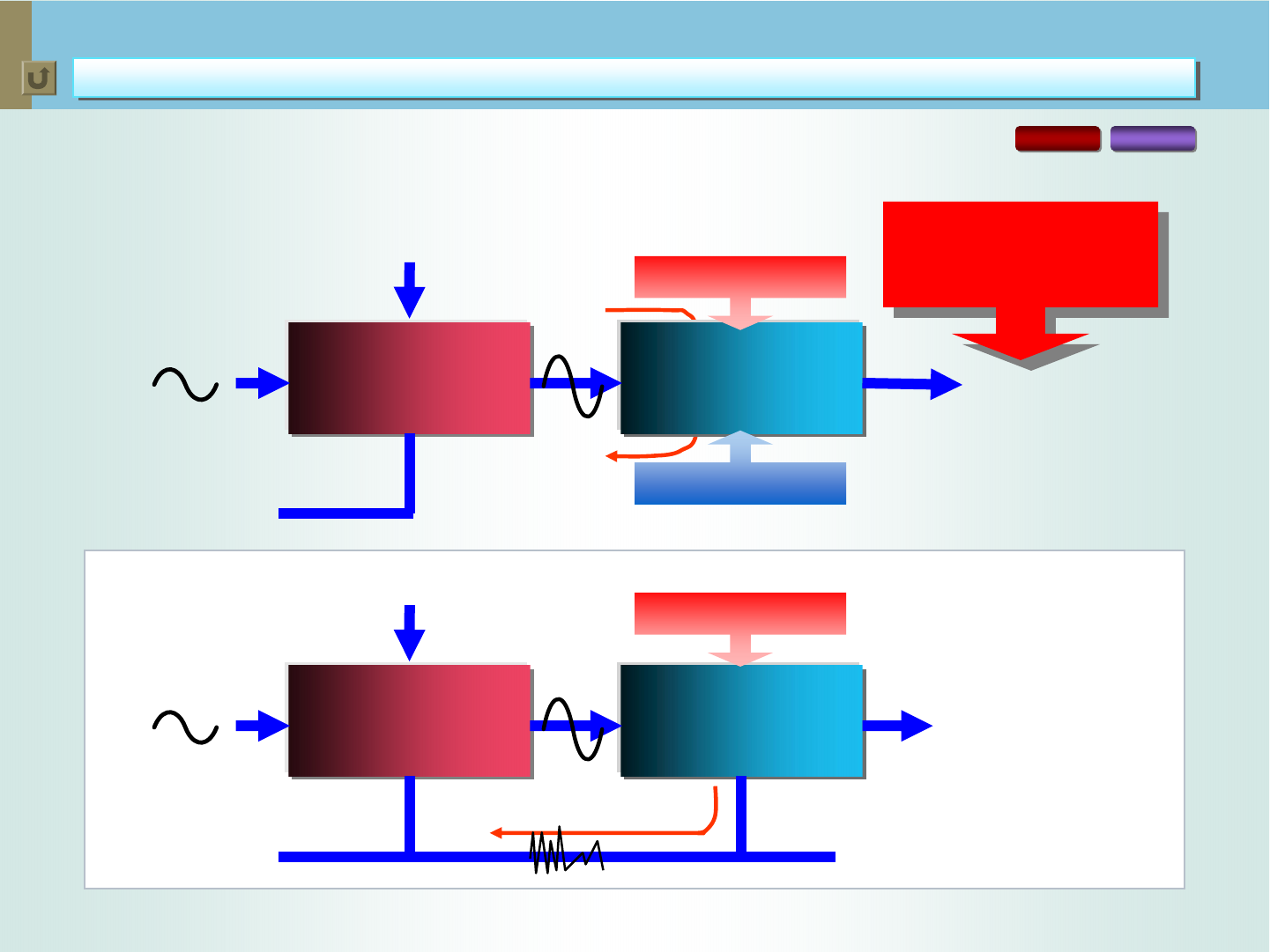
Use of two feedback loops eliminates the noise generated at each process:
Digital feedback -- for significantly improving the precision of PWM signal generation.
Analog feedback -- for “brushing up” the waveform of the analog signal at output to match the original.
Digital feedback -- for significantly improving
the precision of PWM signal generation
Analog feedback -- for “brushing up” the waveform of
the analog signal at output to match the original
1
PWM
*Also applies to RX-D401

< 47 >
JVC technologies for satisfying the THX Ultra2 certification
Hybrid Feedback Digital Amplifier
Hybrid Feedback Digital Amplifier
Evolution of Hybrid Feedback Digital Amplifier (2)
Evolution of Hybrid Feedback Digital Amplifier (2)
PWM
Modulator
Pre-
Driver Demodulator
(LPF)
Phase Shift
Master Clock
+
-
IN
RX-D702 RX-D402
Hybrid Feedback Digital Amplifier Ver. II
Double analog feedback ensures even lower distortion.
Double analog feedback ensures
even lower distortion.
2
PWM
*Also applies to RX-D401
< 48 >
JVC technologies for satisfying the THX Ultra2 certification
Hybrid Feedback Digital Amplifier
Hybrid Feedback Digital Amplifier
Evolution of Hybrid Feedback Digital Amplifier (3)
Evolution of Hybrid Feedback Digital Amplifier (3)
PWM
Modulator
Pre-
Driver Demodulator
(LPF)
Phase Shift
Master Clock
+
-PWM
IN
RX-D702 RX-D402
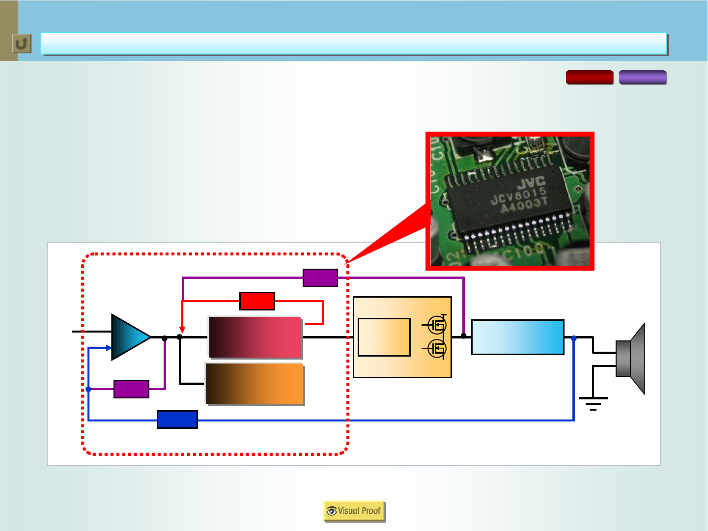
Hybrid Feedback Digital Amplifier Ver. III
Double analog & digital feedback loops for even lower total harmonic distortion.
Use of newly-developed “JCV8015” for containing all the circuits.
Double analog & digital
feedback loops for even lower
total harmonic distortion
JCV8015
3
*Also applies to RX-D401
< 49 >
JVC technologies for satisfying the THX Ultra2 certification
Hybrid Feedback Digital Amplifier
Hybrid Feedback Digital Amplifier Ver
Ver. III
. III
Low-Voltage Power Supply
Low-Voltage Power Supply
Large-Capacity
Power
Transformer
High-Efficiency
Stabilized
Power Supply
Circuit
- Power Supply
+ Power Supply
Digital
Amp
Stabilized
~
Quality
Sound
RX-D702 RX-D402
Hybrid Feedback Digital Amplifier Ver. III also features low voltage power supply,
which ensures stable signal transfer.
*Also applies to RX-D401
< 50 >
JVC technologies for satisfying the THX Ultra2 certification
Hybrid Feedback Digital Amplifier
Hybrid Feedback Digital Amplifier Ver
Ver. III
. III
One-Chip Solution with JCV8015
One-Chip Solution with JCV8015
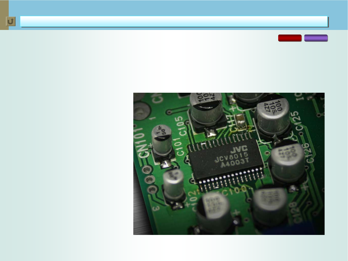
The Hybrid Feedback Digital Amplifier Ver. III features use of a new IC dubbed
“JCV8015”. This superior device, developed by JVC, contains all the circuits necessary
for digital signal processing, including dual audio input circuits, the Hybrid Feedback
Signal Processing Circuit, and PWM modulators. In addition to allowing a drastic
reduction in parts and a smaller “footprint”, JCV8015 comes with the following features:
Superior operational amp for low
distortion and low noise
High-precision PWM modulator --
featuring synchronization by
external clock
Built-in ±2.5V regulator
separated from analog GND
RX-D702 RX-D402
*Also applies to RX-D401
< 51 >
JVC technologies for satisfying the THX Ultra2 certification
Hybrid Feedback Digital Amplifier
Hybrid Feedback Digital Amplifier Ver
Ver. III
. III
JCV8015 Benefits (1) -- Operational Amp
JCV8015 Benefits (1) -- Operational Amp
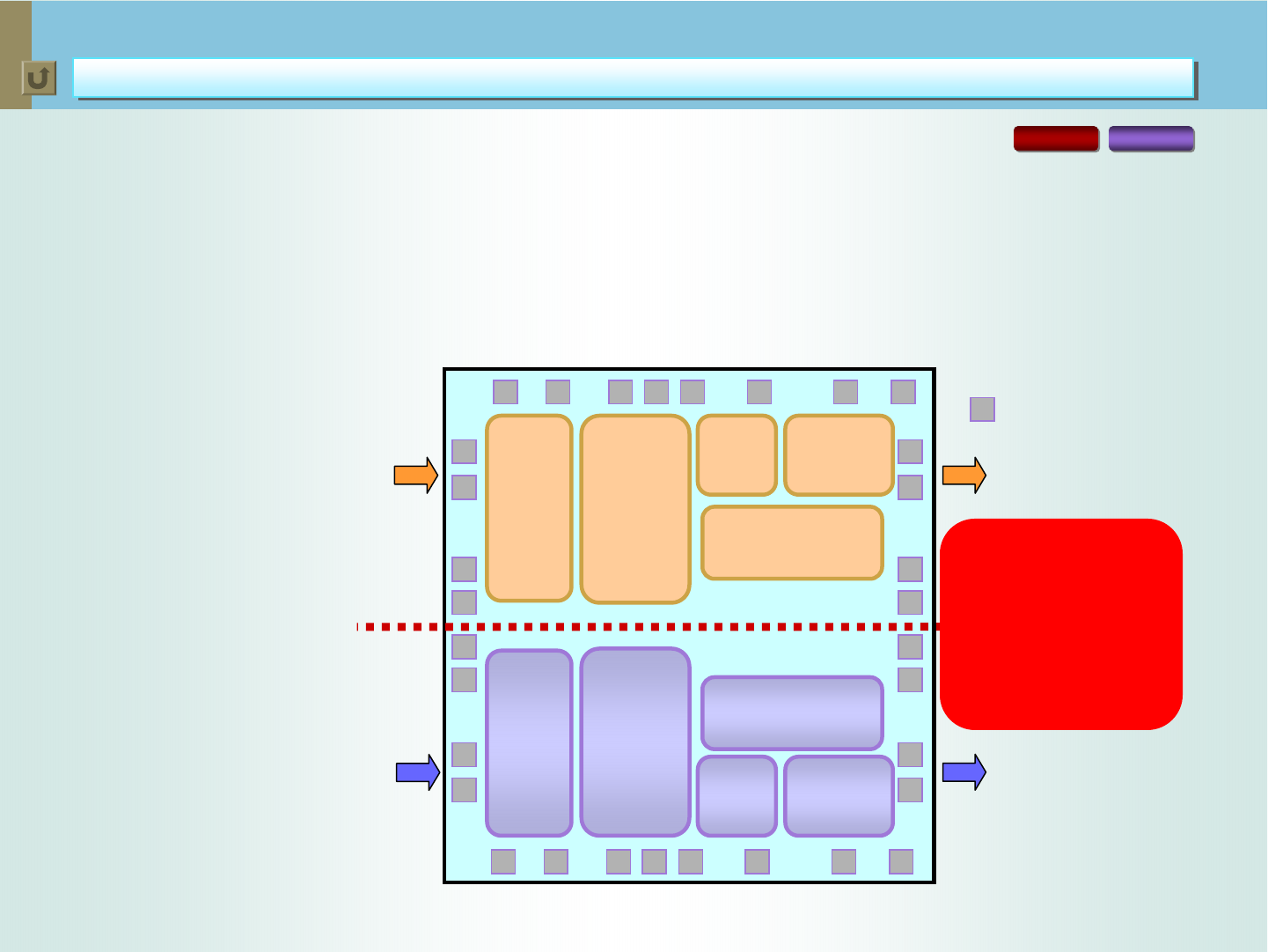
Superior Operational Amp for Low Distortion and Low Noise
High Slew Rate
The operational amp comes with a higher slew rate -- two times higher than the previous
types of devices -- to eliminate instantaneous “cross-modulation distortion”.
JCV8015 -- Layout of Parts and Devices
Interference-Free
Layout
The operational amp
features a symmetrical
layout of parts and
devices, which are
completely separated
for left and right
channels. This prevents
signal interference
between the two
channels (see the figure
at right).
L-ch
R-ch
PAD
L-ch out
R-ch out
Operational
Amp with
High Slew
Rate
Circuit for
Selecting
Max.
Modulation +2.5V
Regulator Symmetrical
Layout
Operational
Amp with
High Slew
Rate
Circuit for
Selecting
Max.
Modulation
Ultra-High-
Speed
Comparator
High-
Precision
Triangular
Waves
Ultra-High-
Speed
Comparator
High-
Precision
Triangular
Waves
-2.5V
Regulator
Parts and devices for left
and right channels are
completely separated.
--> Superior sound
quality with no signal
interference.
RX-D702 RX-D402
*Also applies to RX-D401
< 52 >
JVC technologies for satisfying the THX Ultra2 certification
Hybrid Feedback Digital Amplifier
Hybrid Feedback Digital Amplifier Ver
Ver. III
. III
JCV8015 Benefits (2) -- PWM Modulator/External Clock
JCV8015 Benefits (2) -- PWM Modulator/External Clock
RX-D702 RX-D402
High-Precision PWM Modulator
PWM
Input Audio
Signals
Ultra-High-Speed
Comparator
High-Precision
Triangular Waves
Synchronization by an External Clock
Slight gap of frequencies among channels causes specific noise. To prevent this, the JVC amplifier uses
an external clock, which synchronizes the operations of all channels. Noise is also generated when the unit
receives AM signals whose frequency overlaps that of audio signals. The external clock detects this and
automatically modifies the audio signal frequency of all the channels simultaneously, thus preventing the
noise generation.
High-Precision Triangular Waves
Distortion or irregular angles of the triangular waves
lower the precision of PWM signals, which results in
lower sound quality. The JCV8015 uses high-precision
triangular waves to prevent the problem.
Ultra-High-Speed Comparator
Comparison of audio signals with the triangular waves
is done by “comparator”. The JVC amp features an
ultra-high-speed comparator. This prevents the
possible delay of PWM signals with respect to audio
signals, which causes distortion.
*Also applies to RX-D401
< 53 >
Use of built-in ±2.5V
regulator separates the path
of current in digital circuits
from analog GND.
JVC technologies for satisfying the THX Ultra2 certification
Hybrid Feedback Digital Amplifier
Hybrid Feedback Digital Amplifier Ver
Ver. III
. III
JCV8015 Benefits (3) -- ±2.5V Regulator
JCV8015 Benefits (3) -- ±2.5V Regulator
Analog Signals
Analog GND
PWM
VCC (Analog)
Power supply to digital
circuits causes the current to
interfere with analog GND,
which generates noise.
Digital Circuits
(PWM)
Analog Circuits
(Operational Amp)
PWM
Digital Circuits
(PWM)
Analog Circuits
(Operational Amp)
+2.5V Regulator
-2.5V Regulator
Use of the built-in ±2.5V regulator prevents digital
noise interference to analog GND.
RX-D702 RX-D402
Analog Signals
Analog GND
VCC (Analog)
Improved
Sound Quality
VDD (Digital, 5V)
*Also applies to RX-D401
< 54 >
JVC technologies for satisfying the THX Ultra2 certification
Hybrid Feedback Digital Amplifier
Hybrid Feedback Digital Amplifier Ver
Ver. III
. III
Quality Parts for Superior Sound Reproduction
Quality Parts for Superior Sound Reproduction
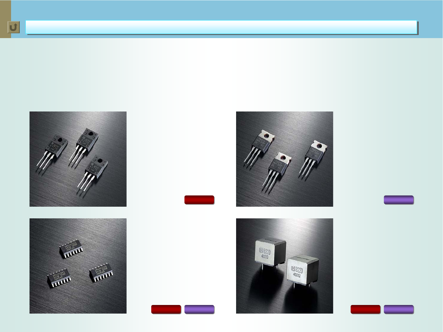
The superior technologies applied for the digital amp combine to lower the total harmonic distortion by a
specific ratio (see the following pages for details). This means when the distortion of input signals are lower,
that of output signals are lower than when input signals have higher distortion. This is why JVC engineers
applied a wide range of quality parts for the A/V receivers. These devices ensure even better sound quality by
sending low-distortion signals to the Hybrid Feedback Digital Amplifier Ver. III.
RX-D402
Power MOSFET used for
the 150W digital amplifier
of the RX-D702.
2SK3770-01MR
IRS20124
IRFB4212
ETQA15
Power MOSFET used for
the 110W digital amplifier
of the RX-D402/D401.
High-performance Driver
IC incorporated in the
digital amplifiers of all
the units.
All the units feature high-
quality coils incorporated
in the output low-pass filter,
which help deliver superior
sound.
RX-D702 RX-D402
RX-D702
RX-D702 RX-D402
< 55 >
JVC technologies for satisfying the THX Ultra2 certification
Hybrid Feedback Digital Amplifier
Hybrid Feedback Digital Amplifier Ver
Ver. III
. III
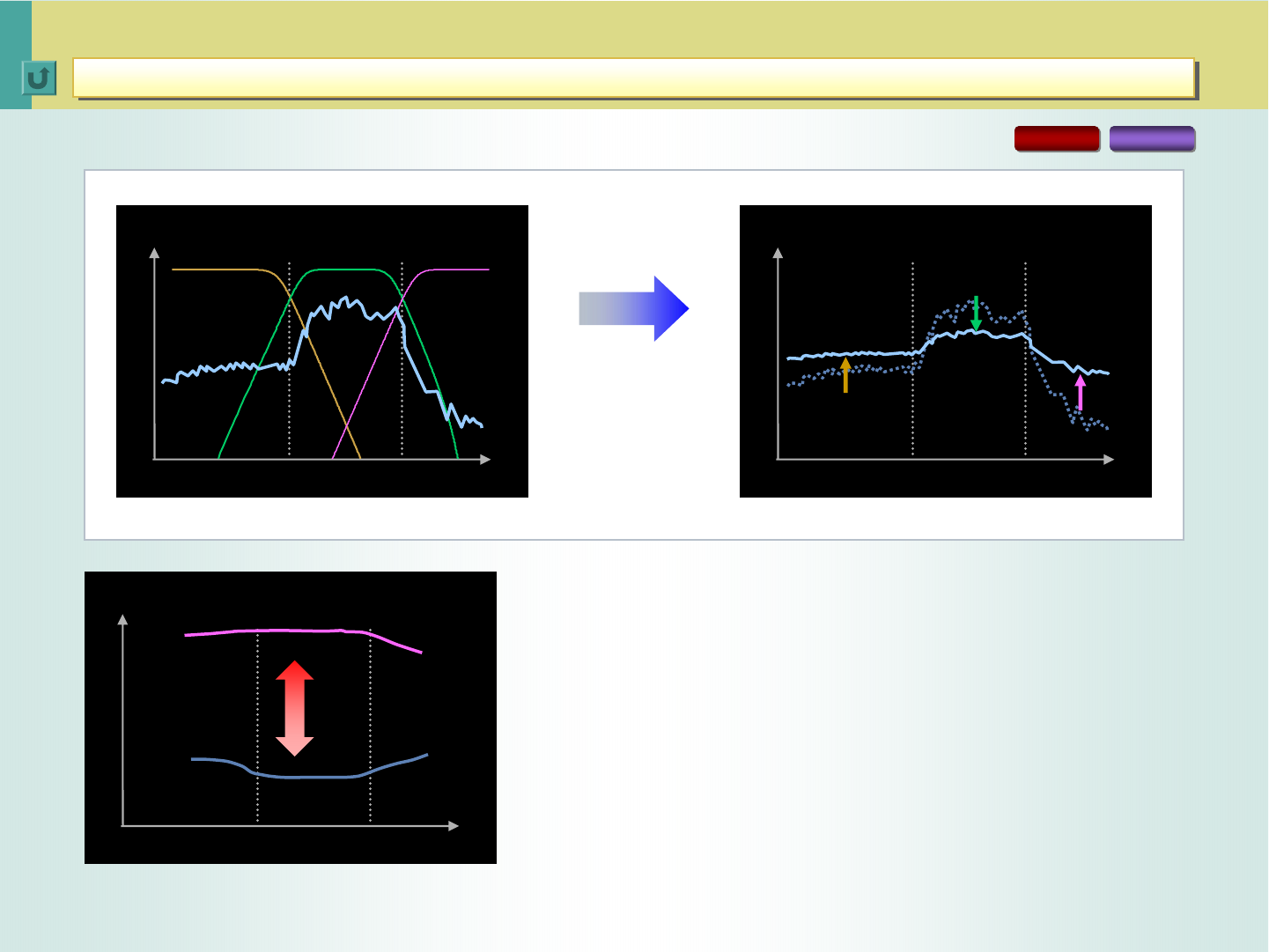
Comparison of Speaker Driveability
RX-D702 RX-D402
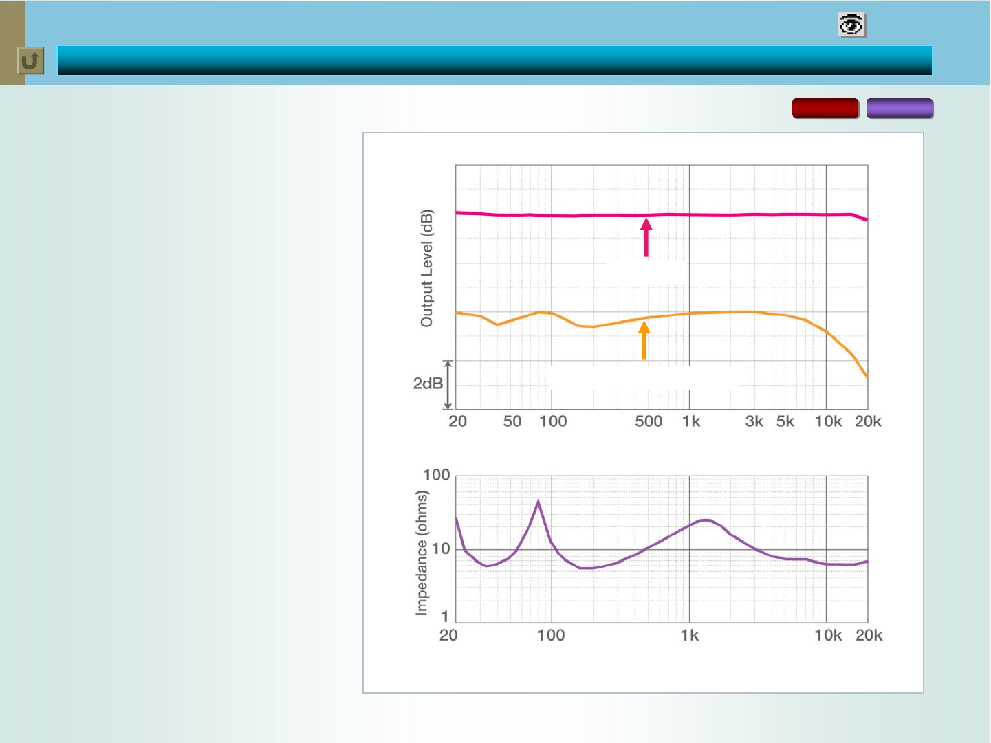
Usually, speaker impedance
fluctuates according to the
frequencies of audio signals.
This “frequency response” of the
speaker in turn fluctuates the
levels of audio signals. How
effectively an amplifier can control
these fluctuations is called
“speaker driveability”.
The feedback processes of the
Hybrid Feedback Digital Amplifier
significantly improve the speaker
driveability, retaining the same
output level across the
frequencies.
VISUAL PROOF
*Also applies to RX-D401
Speaker Impedance with a Typical 2-Way Speaker
RX-D702
Non-Feedback Amp
< 56 >
JVC technologies for satisfying the THX Ultra2 certification
Hybrid Feedback Digital Amplifier
Hybrid Feedback Digital Amplifier Ver
Ver. III
. III
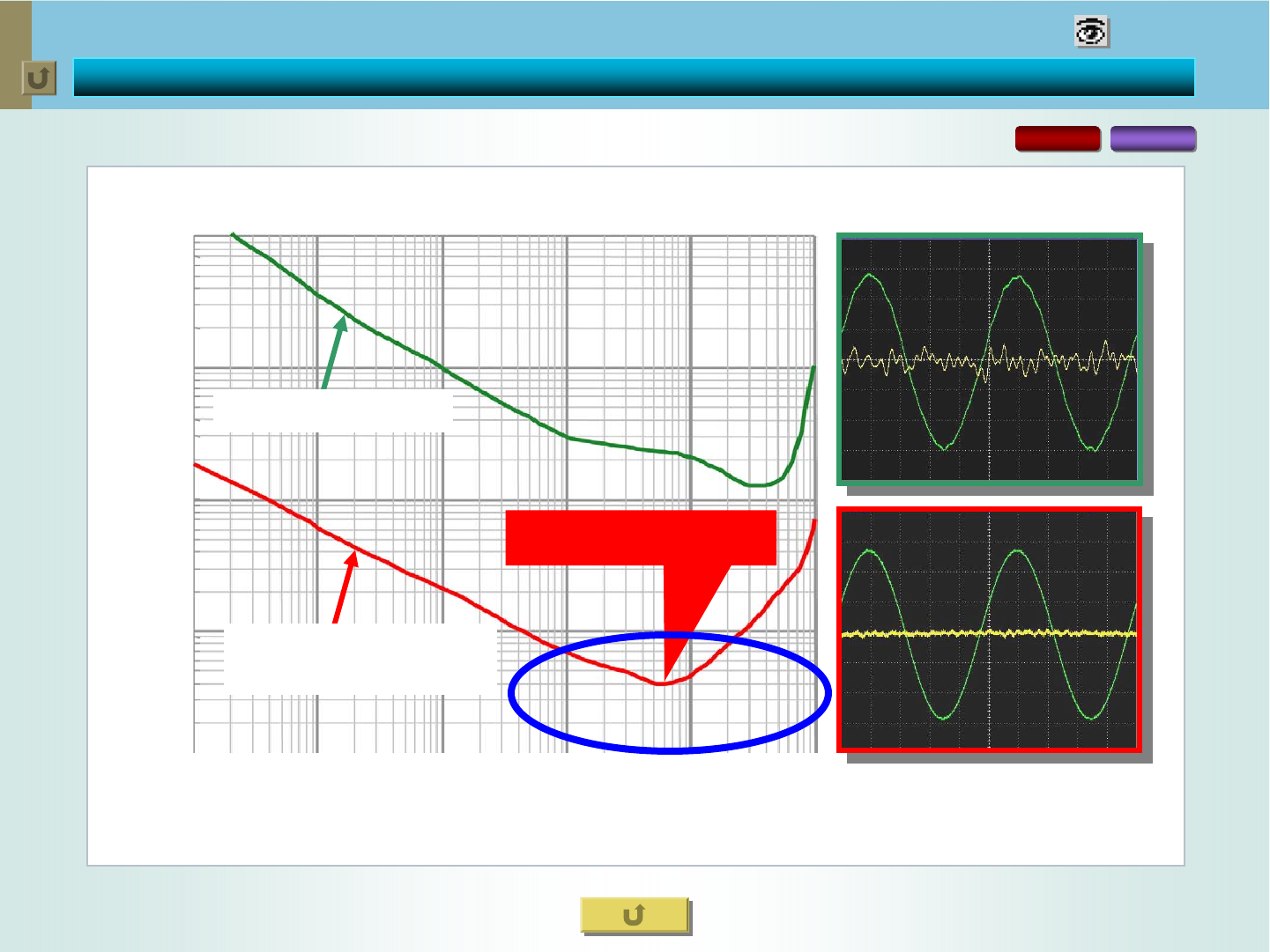
T.H.D. Comparison of Digital Amplifiers
RX-D702 RX-D402
VISUAL PROOF
*Also applies to RX-D401
0.004%
0.01
0.1
1
10
0.001 0.01 0.1 1 10 100
Output Power [W] /6Ω
THD + N [%]
Non-Feedback Amp
Hybrid Feedback
Digital Amp (RX-D702)

< 57 >
Supplementary Information
OSD Superimposed on Screen
OSD Superimposed on Screen
RX-D402B Audio/Video Control Receiver
RX-D402B Audio/Video Control Receiver
RX-D702B Audio/Video Control Receiver
RX-D702B Audio/Video Control Receiver
58
59
60
Rear Panel
Rear Panel 62
Multi-Brand A/V-STB (CATV/DBS) Glow Remote Control
Multi-Brand A/V-STB (CATV/DBS) Glow Remote Control 61
< 58 >
JVC technologies for satisfying the THX Ultra2 certification
OSD Superimposed on Screen
OSD Superimposed on Screen
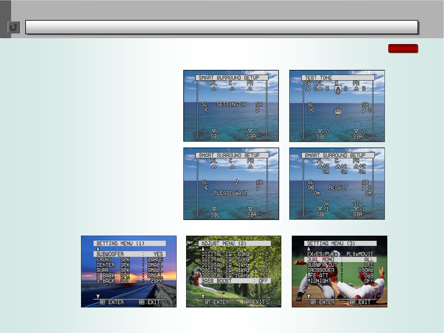
The RX-D702 displays a wide range of
information -- including the Smart Surround
Setup processes -- superimposed on your
monitor screen to ensure easy recognition
and control.
OSD for Smart Surround Setup
Setting Menu Screen Digital EQ and Bass Boost Setup Speaker Setup
RX-D702
< 59 >
JVC technologies for satisfying the THX Ultra2 certification
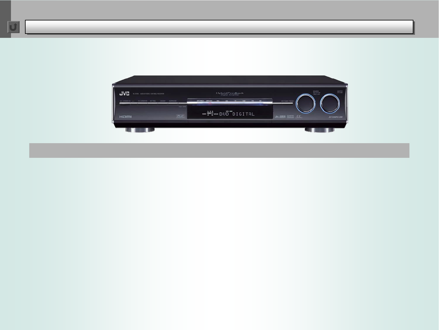
RX-D702B Audio/Video Control Receiver
RX-D702B Audio/Video Control Receiver
Basic Features
• Stereo: 150 watts per channel, 6 ohms, from
20Hz to 20kHz, with 0.8% THD
• Surround: (Front) 150 watts per channel,
6 ohms at 1kHz, with 0.8% THD; (Center)
150 watts, 6 ohms at 1kHz, with 0.8% THD;
(Surround) 150 watts per channel, 6 ohms at
1kHz, with 0.8% THD; (Surround Back) 150
watts per channel, 6 ohms at 1kHz, with 0.8%
THD
• Dolby Digital EX/Dolby Digital/Dolby Pro Logic
IIx/Dolby Pro Logic II
• DTS/DTS-ES/DTS NEO:6/DTS 96/24
• DVD Multi-Channel Audio Compatible
7-Channel Receiver Featuring HDMI, New Digital Amplifier, and Wireless PC Connectivity
Product Highlights
• Hybrid Feedback Digital Amplifier Ver. III
• HDMI – for single-cable, all-digital
transmission of audio and video signals
• Wireless Connection with PC -- enjoy
playback of music files from PC
• CC Converter (2 Modes, Front Channels) --
offers two modes for improving the sound
quality of compressed audio and non-
compressed sources, respectively
• USB Input for receiving audio signals from PC
• SIRIUS Input and SIRIUS Control on Remote
• On-Screen Display
• Center-Channel Alignment
• Virtual Surround Back for creating even wider
sound field without a surround back speaker
• 3D-PHONIC
• DAP for Multi-Channel Digital Sources:
THEATER 1/THEATER 2/HALL 1/ HALL 2/
DANCE CLUB/LIVE CLUB/PAVILION
• DAP for 2-Channel Sources: MONO
FILM/THEATER 1/THEATER 2/HALL 1/
HALL 2/DANCE CLUB/LIVE CLUB/
PAVILION/ALL CH STEREO
• 3D Headphone
• 192kHz/24-bit P.E.M. D.D. Converter
(Front/Center/Surround Channels)
• Video Signal Up-Conversion (to HDMI) for
single-cable output of high-quality video from
any input terminals
• Smart Surround Setup (Ver. 3.0) -- easy
handclap setting up of the acoustic
environment
• One-Touch Operation
• DSP Digital Equalizer
• AV COMPU LINK
• Multi-Brand A/V-STB (CATV/DBS) Glow
Remote Control

< 60 >
JVC technologies for satisfying the THX Ultra2 certification
RX-D402B Audio/Video Control Receiver
RX-D402B Audio/Video Control Receiver
Basic Features
• Stereo: 110 watts per channel, 6 ohms, from
20Hz to 20kHz, with 0.8% THD
• Surround: (Front) 110 watts per channel,
6 ohms at 1kHz, with 0.8% THD; (Center)
110 watts, 6 ohms at 1kHz, with 0.8% THD;
(Surround) 110 watts per channel, 6 ohms at
1kHz, with 0.8% THD; (Surround Back) 110
watts per channel, 6 ohms at 1kHz, with 0.8%
THD
• Dolby Digital EX/Dolby Digital/Dolby Pro Logic
IIx/Dolby Pro Logic II
• DTS/DTS-ES/DTS NEO:6/DTS 96/24
• DVD Multi-Channel Audio Compatible
7-Channel Receiver with HDMI, PC Connection via USB and New Digital Amplifier
Product Highlights
• Hybrid Feedback Digital Amplifier Ver. III
• HDMI -- for single-cable, all-digital
transmission of audio and video signals
• Video Up-Conversion (to HDMI) for single-
cable output of high-quality video from any
input terminals
• USB Input for receiving audio signals from PC
• Center-Channel Alignment
• Virtual Surround Back for creating even wider
sound field without a surround back speaker
• 3D-PHONIC
• DAP for Multi-Channel Digital Sources:
THEATER 1/THEATER 2/HALL 1/HALL 2/
DANCE CLUB/LIVE CLUB/PAVILION
• DAP for 2-Channel Sources: MONO
FILM/THEATER 1/THEATER 2/HALL 1/
HALL 2/DANCE CLUB/LIVE CLUB/
PAVILION/ALL CH STEREO
• 3D Headphone
• 192kHz/24-bit P.E.M. D.D. Converter
(Front/Center/Surround Channels)
• Quick Speaker Setup
• One-Touch Operation
• DSP Digital Equalizer
• AV COMPU LINK
• Multi-Brand A/V-STB (CATV/DBS) Glow
Remote Control

< 61 >
JVC technologies for satisfying the THX Ultra2 certification
Multi-Brand A/V-STB (CATV/DBS) Glow Remote Control
Multi-Brand A/V-STB (CATV/DBS) Glow Remote Control
For RX-D702B For RX-D402B/RX-D401S
< 62 >
JVC technologies for satisfying the THX Ultra2 certification
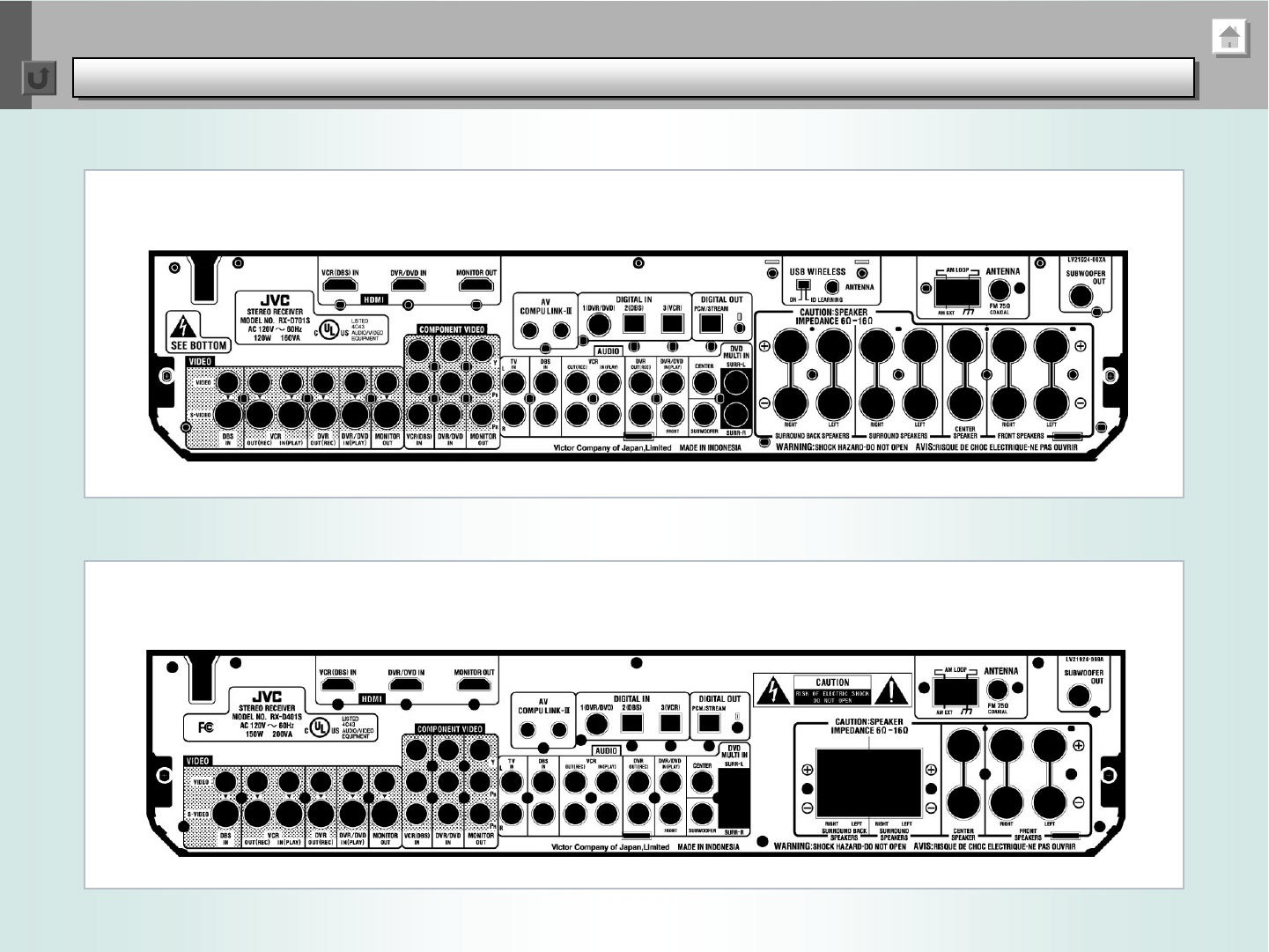
Rear Panel
Rear Panel
RX-D702B
RX-D402B/RX-D401S

< 63 >
