K Best Technology 5117R E1 Spread Spectrum Radio User Manual 2
K-Best Technology Inc. E1 Spread Spectrum Radio 2
Contents
- 1. User Manual 1
- 2. User Manual 2
User Manual 2
Configuration
E1 Spread Spectrum Radios
7-1
7 Configuration
7.1 Configure via Telnet
The given example uses Microsoft Windows XP. For other OS, please assess accordingly.
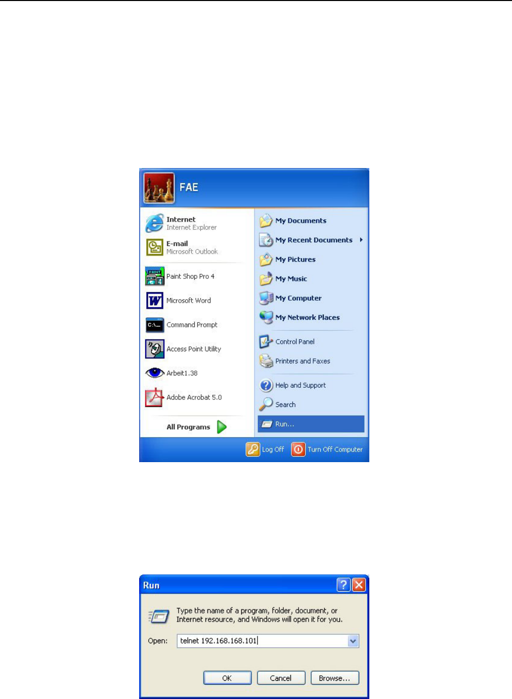
STEP 1: Click Start Æ Run.
Figure 7-1 Configuration Process of telnet (1)
STEP2: In the Run window enter command: telnet xxx.xxx.xxx.xxx.
9 Default IP is 192.168.168.101.
Configuration
E1 Spread Spectrum Radios
7-2
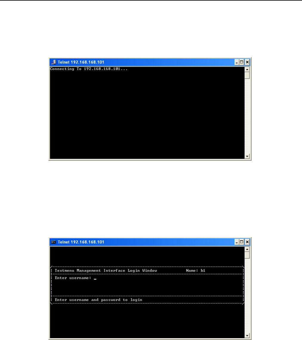
Figure 7-2 Configuration Process of telnet (2)
STEP3: Click OK to continue.
Figure 7-3 Configuration Process of telnet (3)
STEP4: Enter username
9 Default username: root.
Figure 7-4 Enter Username
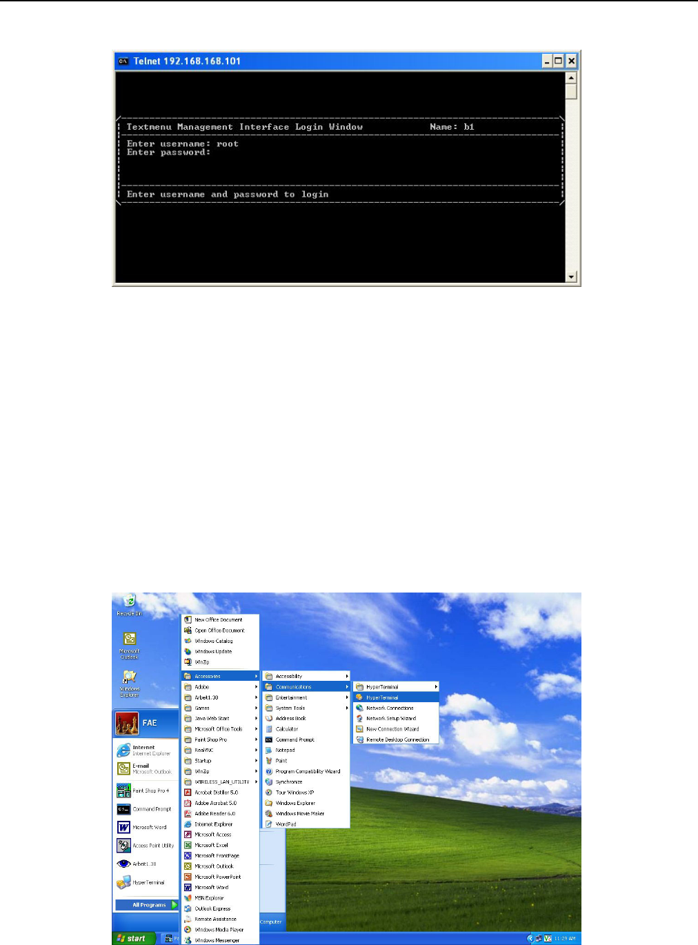
STEP5: Enter password
9 Default password: root.
Configuration
E1 Spread Spectrum Radios
7-3
Figure 7-5 Enter Password
Then you could access textmenu to configure or setup detail parameters.
9 We strongly recommend that after you setup all the parameters, you should change your password for
security reason.
7.2 Configure via HyperTerminal
The given example uses Microsoft Windows XP. For other OS, please assess accordingly.
STEP 1: Click Start Æ Accessories Æ Communications Æ HyperTerminal.
Configuration
E1 Spread Spectrum Radios
7-4
Figure 7-6 Configuration Process of HyperTerminal (1)
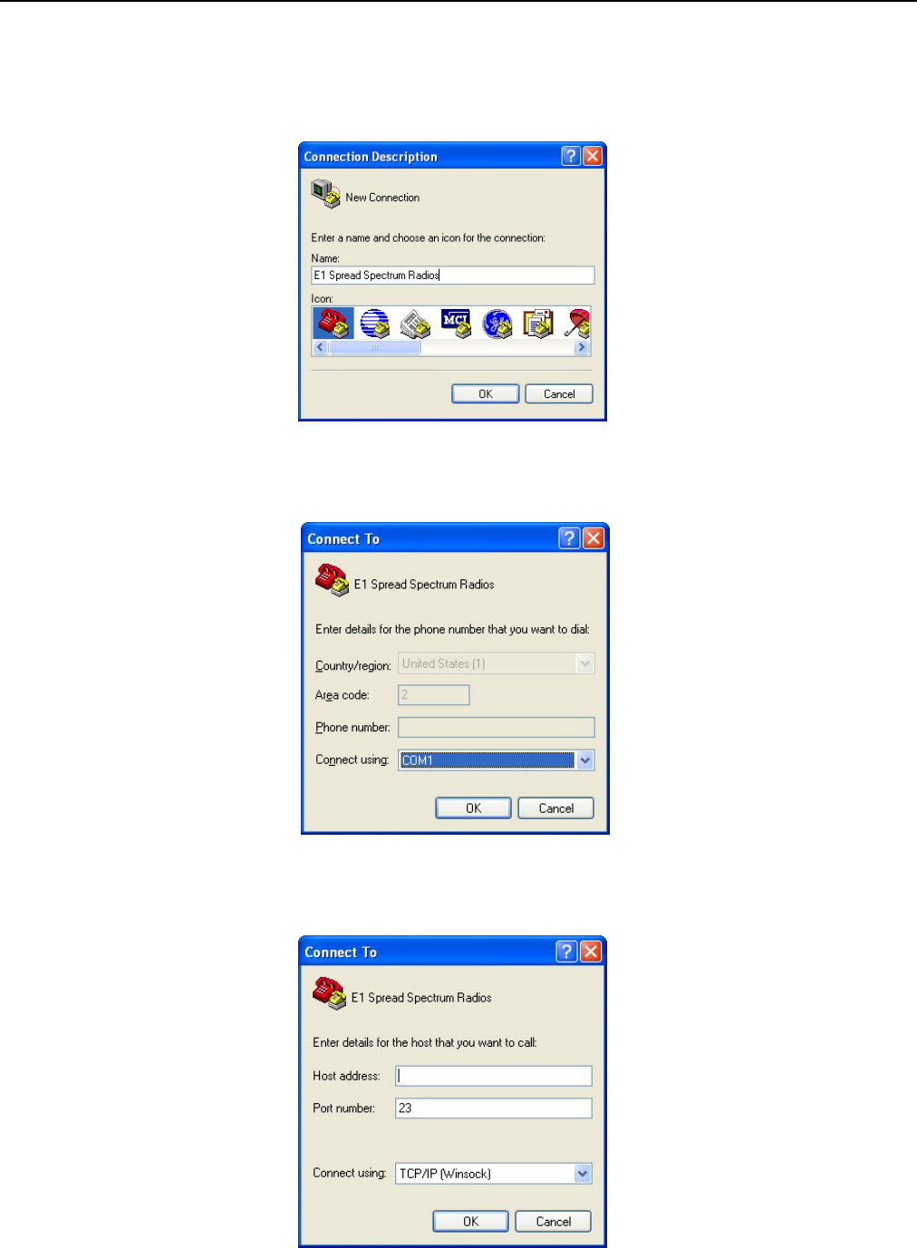
STEP2: Fill in the connection name in the column. Then press “OK” to continue.
Figure 7-7 Configuration Process of HyperTerminal (2)
STEP3: Choose the item of “connect using” to be TCP/IP(Winsock)”.
Figure 7-8 Configuration Process of HyperTerminal (3)
STEP4: Fill in the IP address of the ETH port. The port number left to be default value of 23. Then press “OK”.
Configuration
E1 Spread Spectrum Radios
7-5
Figure 7-9 Configuration Process of HyperTerminal (4)
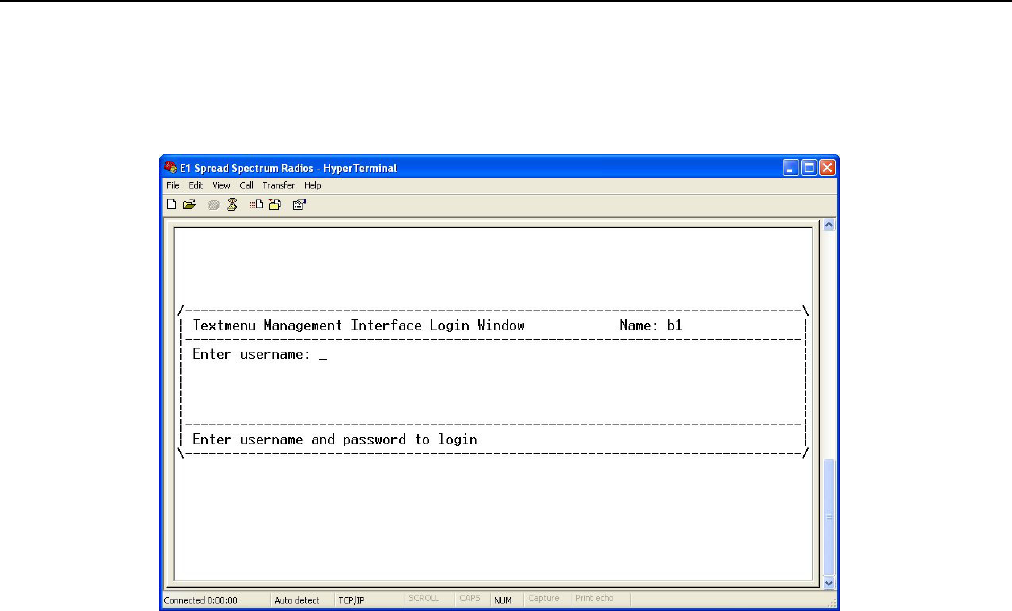
STEP5: You will enter the login windows of HyperTerminal.
Figure 7-10 Configuration Process of HyperTerminal (5)
STEP6: Then enter username and password. You will enter the textmenu configuration.
9 We suggest you use the telnet to enter the textmenu. Because telnet could be operated in various
operation systems.
Textmenu Details
E1 Spread Spectrum Radios
8-1
8 Textmenu Details
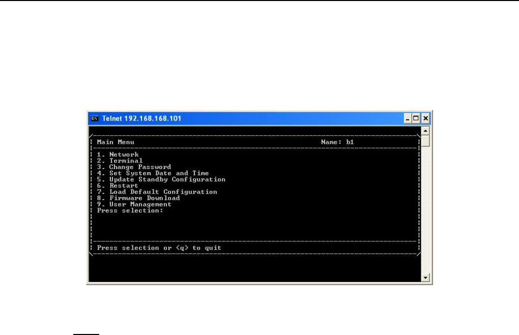
After you login successfully, you will access the following windows of textmenu.
Figure 8-1 Main Menu of Textmenu
Note: Problems that might have occurred in using textmenu:
1. You might be incapable of deleting the words or selection you entered by backspace key. You could
delete the words or selection by delete key or login via other telnet tools to implement your operation.
2. When you get event record, if you have no action for a long while, the information would be printed
gradually in the windows instead of output to be a file. You should operate this command in the short
period of time to avoid this situation.
3. If you login in the older version operation system such as Windows 95,98, the page would not display
correctly. This is because that telnet tools version of operation system are older to automatically adjust
screen manifest. We recommend using other telnet tools other than one in the operation system.
8.1 Network
In this page, you could setup all the network parameters such as IP address, Peer IP address, IP routing,
SNMP setting etc.
Textmenu Details
E1 Spread Spectrum Radios
8-2
Figure 8-2 Network
9 After you made any configuration of change in the item, you should restart to make the setting or change
into effective.
8.1.1 NMS1 Serial Interface
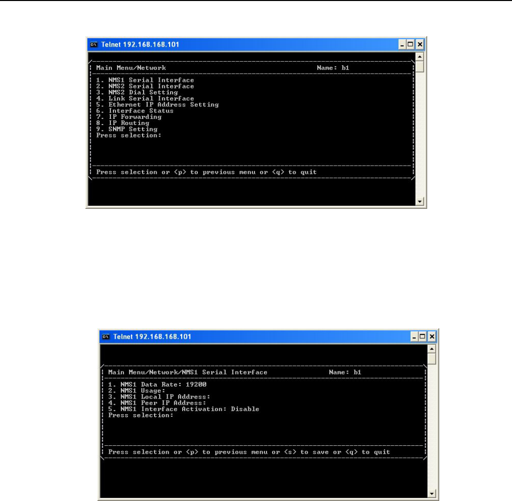
Figure 8-3 NMS1 Serial Interface
In this subpage, you could configure information of NMS1 interface.
NMS1 Data Rate: Data rate of NMS1 setting. There are 5 optional speeds: 9600, 19200, 38400, 57600,
115200. Default value is 19200.
9 We recommend that you should set the value to 115200.
NMS1 Usage: There are 3 optional usages: Master Null Modem, Slave Null Modem, Connect with Computer.
When NMS1 port establishes PPP connection with other equipments, you should choose value “Master Null
Modem” in one end of the connection and “Slave Null Modem” in the other end. The NMS1 IP of equipment
Textmenu Details
E1 Spread Spectrum Radios
8-3
which chooses to be “Slave Null Modem” is assigned by the Master equipment. Therefore, you don’t have to
setup NMS1 IP of slave modem. When NMS1 port is to connect with computer, please choose “Connect with
Computer”.
NMS1 Local IP Address: IP address of NMS1 port in local equipment.
NMS1 Peer IP Address: IP address of NMS1 port in remote equipment when PPP connection is established.
NMS1 Interface Activation: Enable or disable of NMS1 port. When you have to establish PPP connection via
NMS1 port, you should set the value to “Enable”.
8.1.2 NMS2 Serial Interface
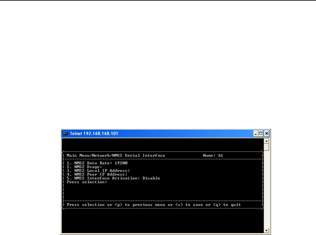
Figure 8-4 NMS2 Serial Interface
In this subpage, you could configure information of NMS2 interface.
NMS2 Data Rate: Data rate of NMS2 setting. There are 5 optional speeds: 9600, 19200, 38400, 57600,
115200. Default value is 19200.
9 We recommend that you should set the value to 115200.
NMS2 Usage: There are 4 optional usages: Master Null Modem, Slave Null Modem, Connect with Computer,
and External Modem.
When NMS1 port establishes PPP connection with other equipments, you should choose value “Master Null
Modem” in one end of the connection and “Slave Null Modem” in the other end. The NMS2 IP of equipment
which chooses to be “Slave Null Modem” is assigned by the Master equipment. Therefore, you don’t have to
setup NMS2 IP of slave modem. When NMS2 port is to connect with computer, please choose “Connect with
Computer”. When you have to connect modem to external modem such as dial-up modem, please choose
“External Modem”.
NMS2 Local IP Address: IP address of NMS2 port in local equipment.
NMS2 Peer IP Address: IP address of NMS2 port in remote equipment when PPP connection is established.
Textmenu Details
E1 Spread Spectrum Radios
8-4
NMS2 Interface Activation: Enable or disable of NMS2 port. When you have to establish PPP connection via
NMS2 port, you should set the value to “Enable”.
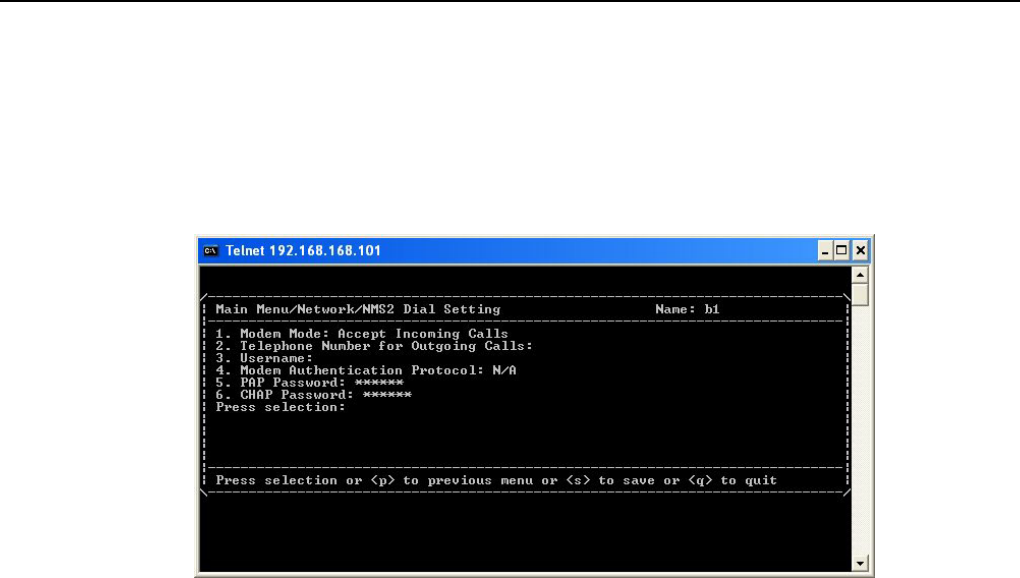
8.1.3 NMS2 Dial Setting
Figure 8-5 NMS2 Dial Setting
In this subpage, you could configure dialing information of NMS2 interface.
Modem Mode: There are two options: “Accept Incoming Call” or “Dial Out at Once”. “Accept Incoming Call”
could connect with computer or other equipment via PPP. If you want to make connection, PPP parameters
should be setup. “Dial Out at Once” could make you make outgoing calls. If it loses connection, it will redial.
Telephone Number of Outgoing Calls: Set the outgoing telephone number. It should be used in modem
mode(item 2) of “Dial Out at Once”.
Username: Username for dial out service.
Modem Authentication Protocol: Authentication protocol setting of the modem. There are three options:
“PAP”, “CHAP”, “N/A”. The default value is “N/A”.
PAP Password: When PAP is chose for dial out service, this password is activated.
9 PAP: Password Authentication Protocol
CHAP Password: When CHAP is chose for dial out service, this password is activated.
9 CHAP(Challenge-Handshake Authentication Protocol):PPP server protocol for establishing connection.
The protocol applies for three-parties handshake and is more secure than PAP.
Textmenu Details
E1 Spread Spectrum Radios
8-5
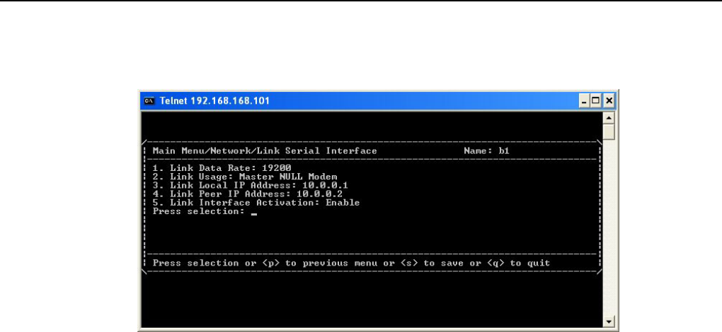
8.1.4 Link Serial Interface
Figure 8-6 Link Serial Interface
In this subpage, you could configure information of Link interface.
Link Data Rate: Data rate of Link setting. There are 2 optional speeds: 9600, 19200. Default value is 19200.
9 We recommend that you should set the value to 19200.
Link Usage: There are 2 optional usages: Master Null Modem, Slave Null Modem.
When Link port establishes RF connection with other equipments, you should choose value “Master Null
Modem” in one end of the connection and “Slave Null Modem” in the other end. The Link IP of equipment
which chooses to be “Slave Null Modem” is assigned by the Master equipment. Therefore, you don’t have to
setup Link IP of slave modem.
Link Local IP Address: IP address of Link port in local equipment.
Link Peer IP Address: IP address of Link port in remote equipment when RF connection is established.
Link Interface Activation: Enable or disable of Link port. When you have to establish RF connection via Link
port, you should set the value to “Enable”.
Textmenu Details
E1 Spread Spectrum Radios
8-6
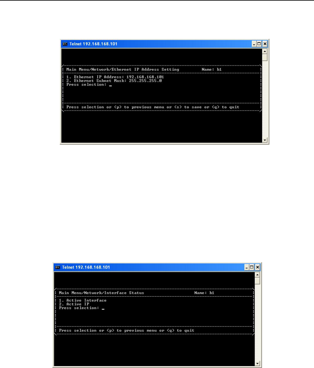
8.1.5 Ethernet IP Address Setting
Figure 8-7 Ethernet IP Address Setting
In this subpage, you could configure IP address and subnet mask of ETH port.
Ethernet IP Address: IP address of ETH LAN(please refer to section 4.1.1) port.
Ethernet Subnet Mask: Subnet mask of ETH LAN port.
9 This item allows you to access and manage the system via Ethernet after correctly setting.
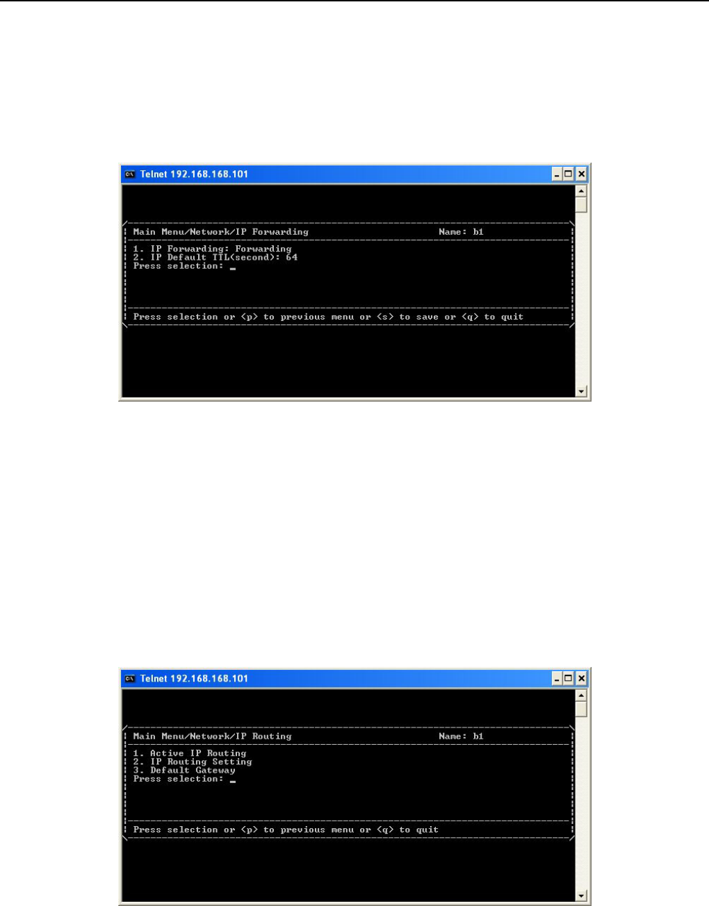
8.1.6 Interface Status
Figure 8-8 Interface Status
This subpage will display the current interfaces condition.
Active Interface: This item shows interface status. You could immediately “Down” the PPP connection
already in place, including the “Up” and PPP link which has been “Down”. You could select one interface and
activate or deactivate the interface by choosing “Up” or “Down”.
Textmenu Details
E1 Spread Spectrum Radios
8-7
Active IP: This item displays the current IP address and subnet mask. After PPP is connected, the
corresponding IP addresses will be shown in this window.
8.1.7 IP Forwarding
Figure 8-9 IP Forwarding
In this subpage, you could setup IP forwarding configurations.
IP Forwarding: Whether IP packet is forwarding. When selected “Forwarding” and connection is established
with other equipments, the IP packet would forward to other equipments. all the IP packet will be forwarding.
Default setting will be “Forwarding”.
IP Default TTL: Meaning how many times of “Forwarding” did an IP packet experience before loss. Default
value is 64.
8.1.8 IP Routing
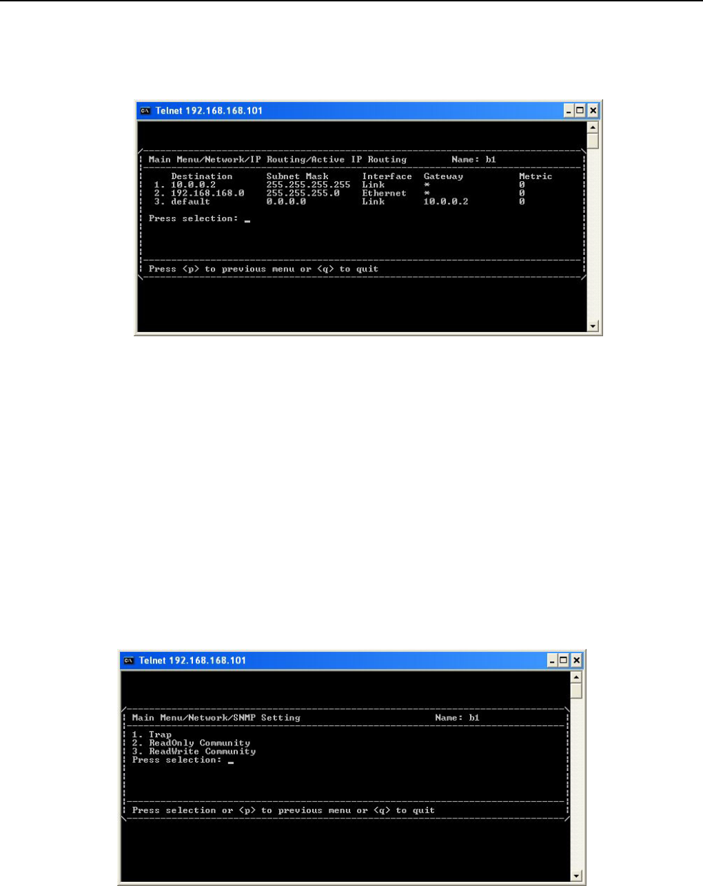
Figure 8-10 IP Routing
The subpage shows the IP Routing status in active, the default route will be in the form of Ethernet, when the
Textmenu Details
E1 Spread Spectrum Radios
8-8
interface formed PPP connection, a point-to-point PPP route will be formed automatically, and other routes will
be formed after settings. Textmenu supports up to 15 static routing setting rules.
Figure 8-11 Active IP Routing
Active IP Routing: This item shows the current active IP routing status.
9 Destination will be the routes’ targeted address, subnet mask will be the subnet mask of targeted address,
interface will be the path of which routing takes, Gateway will be routing’s next hop address, and metric
will be the statistics of routing in order for it to reach the destined address.
IP Routing Setting: This item allows you to add, delete, and save the IP Routing configurations.
Default Gateway: This item allows you to set the values of default gateway interface and address.
8.1.9 SNMP Setting
Figure 8-12 SNMP Setting
This subpage allows you to set the SNMP related configurations. There are three items.
Textmenu Details
E1 Spread Spectrum Radios
8-9
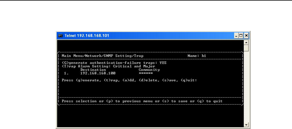
Trap: This item allow you to set the Trap function of SNMP.
Figure 8-13 Trap
Trap/Generate authentication-failure traps: This item can be set as “YES” or “NO”. When set as “YES”, if
there’s an intrusion by unauthorized user, an illegal “Trap” will occur. The default setting is “YES”.
Trap/Trap Alarm Setting: This item can select “Critical”, “All”, or “None”. After selection, when an alarm is
issued under the denoted setting, a trap will be cast upon the destination address. The default setting is “All”.
Trap/Destination: As the Trap destination address. The system could support up to 10 trap destinations.
Trap/Community: As the Trap community string setting.
SNMP ReadOnly Community: This item allows you to change community of “GET” command.
9 The default value is “Public”.
SNMP ReadWrite Community: This item allows you to change community of “SET” command.
9 The default value is “Private”.
Textmenu Details
E1 Spread Spectrum Radios
8-10
8.2 Terminal
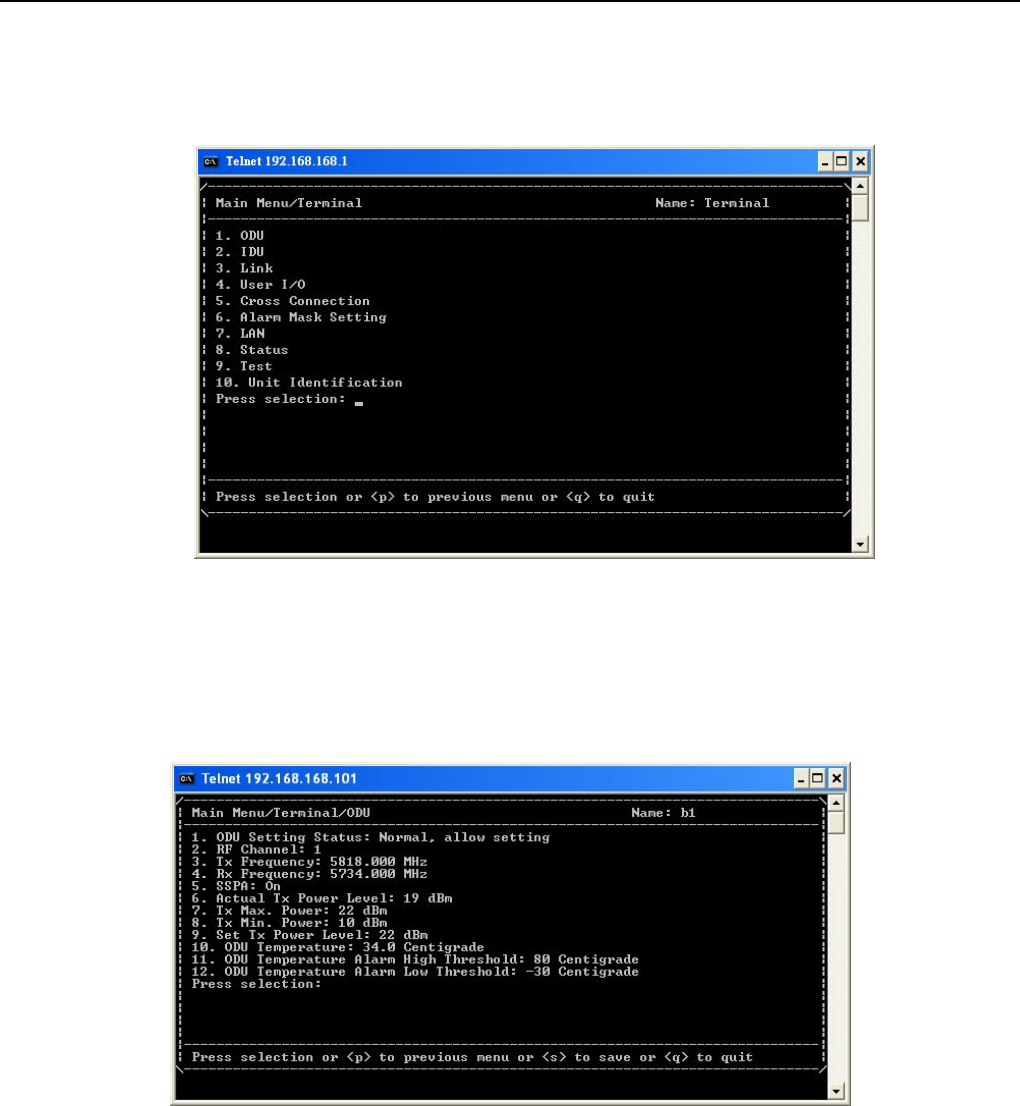
Figure 8-14 Terminal
This page shows terminal statistics and settings display window.
8.2.1 ODU
Figure 8-15 ODU
In this subpage, you could set the configuration or check the status of ODU.
ODU Setting Status: This item displays the current ODU setting status.
9 When not connecting to ODU, each ODU’s status is “Unknown”. At this moment any setting amendment
is not allowed, only after connecting with ODU, the above statistics could then be amended.
Textmenu Details
E1 Spread Spectrum Radios
8-11
RF Channel: This item allows you to set RF channel settings.
Tx Frequency: The display of transmitting frequency.
Rx Frequency: The display of receiving frequency.
SSPA: This item allows you to set the Solid State Power Amplifier.
Actual Tx Power Level: This item shows the actual Tx power level.
Tx Max Level: This item shows maximum Tx power level.
Tx Min Level: This item shows minimum Tx power level.
Set Tx Power Level: This item allows you to set Tx output power level.
ODU Temperature: This item shows ODU’s actual temperature condition.
ODU Temperature Alarm High Threshold: This item shows ODU’s upper temperature limit setting.
ODU Temperature Alarm Low Threshold: This item shows ODU’s lower temperature limit setting.
9 The temperature threshold of ODU fixes to -30~80℃.
8.2.2 IDU
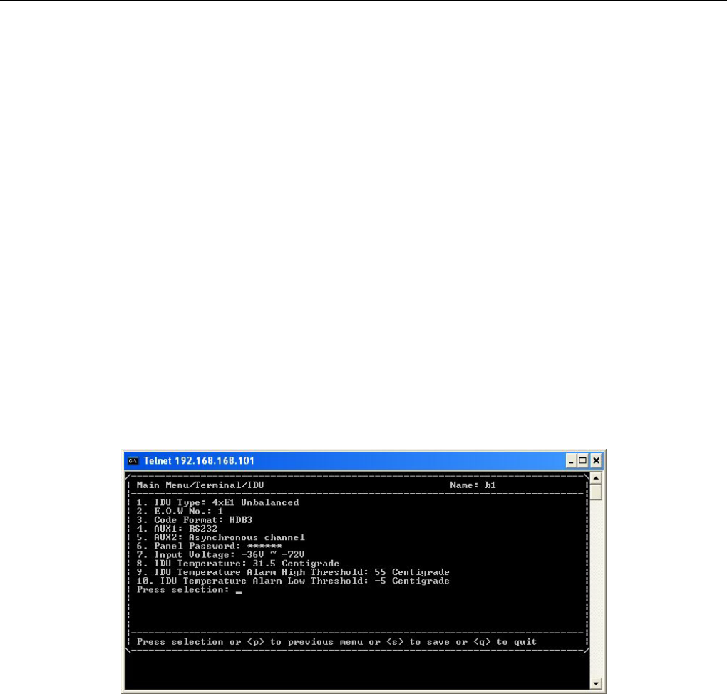
Figure 8-16 IDU
In this subpage, you could set the configuration or check the status of IDU.
IDU Type: This item displays the system capacity and interface type.
EOW No: This item shows Engineering OrderWire number. The range is between 1~255.
Code Format: This items show the setting of code format in E1 interface. There are two optionals:HDB3, and
AMI. The default value is “HDB3”.
AUX1: This item shows the protocol of AUX1. It has selections of “RS232” and “RS422”. The default value is
“RS232”.
AUX2: This item shows the connection type of AUX2. It has selections of “Asynchronous channel” and
“Synchronous channel”. The default value is “Asynchronous channel”.
Panel Password: The password setting of LCD panel. The default value is “000000”.
Textmenu Details
E1 Spread Spectrum Radios
8-12
Input Voltage: This item shows the input power voltage.
IDU Temperature: This item shows IDU’s actual temperature condition.
IDU Temperature Alarm High Threshold: This item shows IDU’s upper temperature limit setting.
IDU Temperature Alarm Low Threshold: This item shows IDU’s lower temperature limit setting.
9 The temperature threshold of IDU fixes to -5~55℃。
After you make any configuration, you should select <s> to save into memory. If the configuration failed, the
error will display on window. The status of window will not fresh immediately. You should quit and reenter the
windows for fresh information.
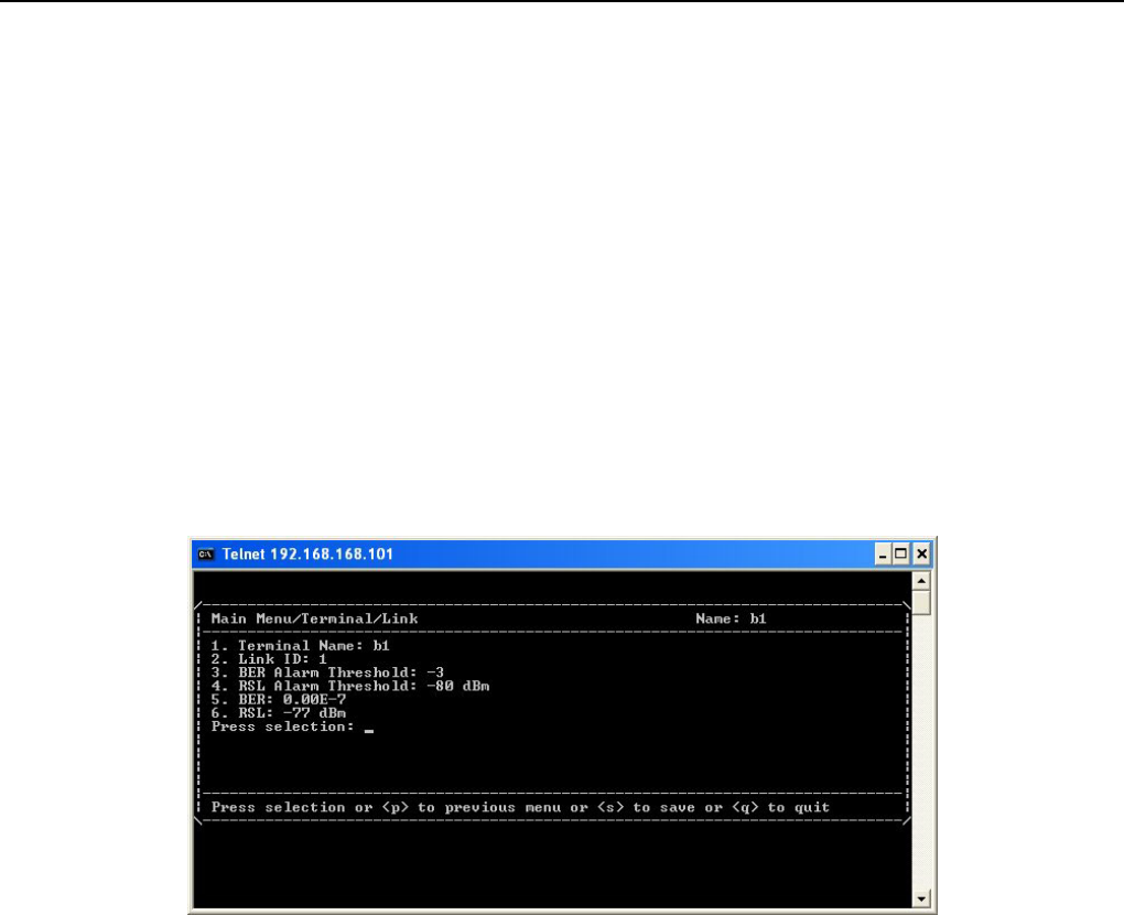
8.2.3 Link
Figure 8-17 Link
In this subpage, you could set the configuration or check the status of Link.
Terminal Name: This item allows you to set the name of terminal. It will be shown in the upper right side of
textmenu. The length is up to 15 characters which allow only letters, digits, space, line, underline, spot and the
first character should be letter.
Link ID: This item allows you to set the number of Link ID.
BER Alarm Threshold: This item allows you to set the threshold of BER(Bit Error Rate) alarm. There are four
options: “-3”, “-4”, ”-5”, and ”-6” which mean 10-3, 10-4, 10-5, and 10-6.
RSL Alarm Threshold: This item allows you to set the threshold of RSL(Receive Signal Level) alarm. The
optional range is from “-50” dBm to “-80” dBm.
BER: This item shows current BER.
RSL: This item shows current RSL.
Textmenu Details
E1 Spread Spectrum Radios
8-13
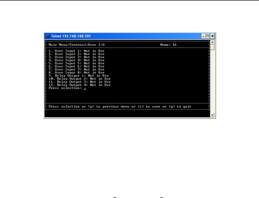
8.2.4 User I/O
Figure 8-18 User I/O
This subpage allows you to set the configurations of User I/O interfaces.
9 Besides the standard E1 interface, there are the User I/O ports. This allows the users to fully control the
controlling room from the local end. For example: If there is no manual control over the remote end, it is
possible to have all the date of temperature, alarm, power supply etc. from the central controlling
computer. The central controlling computer controls most of the functions which makes intelligent
management possible. This device has 8 ports for input and 4 relay output ports.
8 input ports: Setting can be Not in Use status or Alarm on Low status.
4 relay output ports: Setting can be Not in Use status, or Always Open status, or Always Closed status, or
Closed on Input Alarm status, or Closed on Alarm status. For either of these, you may select either of Rx or
Tx.
Textmenu Details
E1 Spread Spectrum Radios
8-14
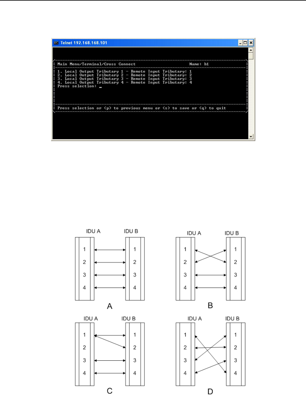
8.2.5 Cross Connect
Figure 8-19 Cross Connect
This subpage allows you to set E1 cross-over connection settings.
9 With the need of adjusting the controlling room channel, the local and remote end E1 Interface have
certain asymmetric variation. The system administrator need not have to manually switch the lines. The
following diagram shows the 4E1 equipment cross connection between local end, IDU A, and remote end,
IDU B.
Figure 8-20 Cross Connection Diagram
Textmenu Details
E1 Spread Spectrum Radios
8-15
Figure A: Normal connection mode.
Figure B: Local and remote port1 & port2 in cross connection mode and port3 & port4 in normal connection
mode.
Figure C: Local port1 connected to remote port1 & port2. Local and remote port3 & port4 are in normal
connection mode.
Figure D: Local and remote port in cross connection mode between ports 1&4, 2&2, 3&1 and 4&3.
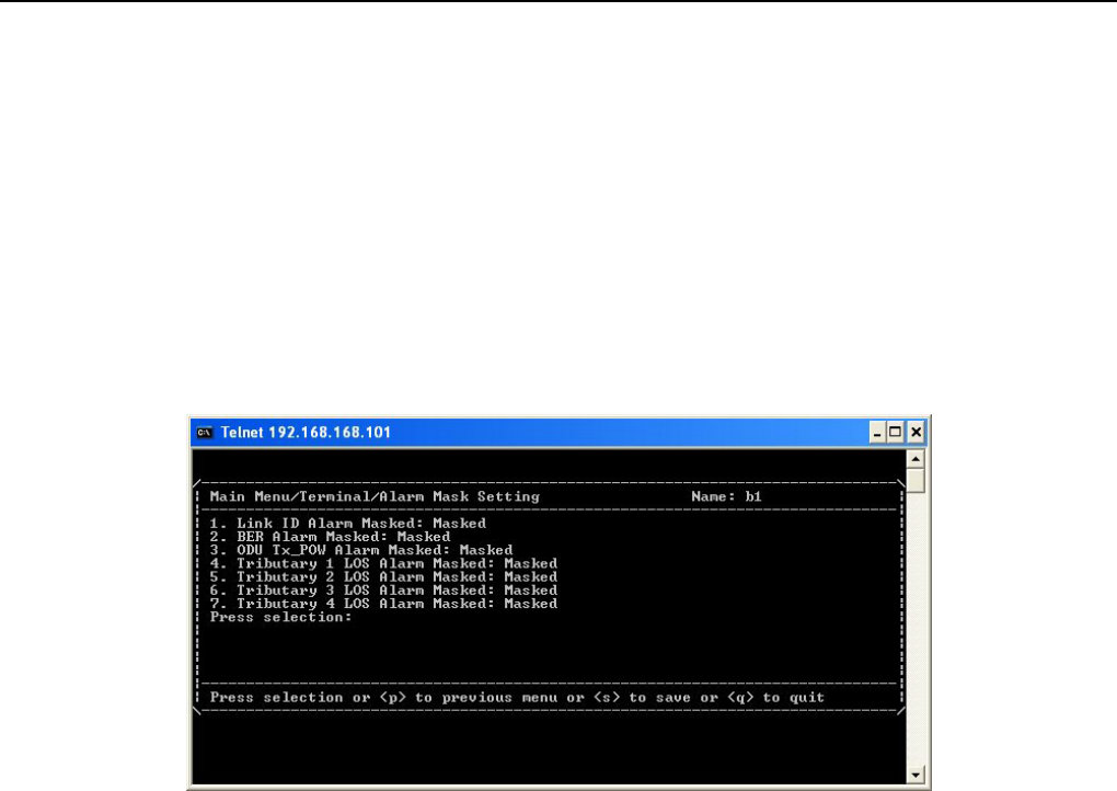
8.2.6 Alarm Mask Setting
Figure 8-21 Alarm Mask Setting
This subpage allows you to set the configurations to whether or not mask some of the alarms.
9 When the IDU goes into a critical state, the alarm will start beeping. However, in some cases like if the
administrator considers the Link ID unimportant, s/he may tick masked and turns off all the alarm
functions.
Link ID Alarm Masked: The alarm that local and peer remote equipments don’t have the same Link ID.
BER Alarm Masked: The alarm that BER has been over the threshold.
ODU Tx_POW Alarm Masked: The alarm that ODU output power has been over the threshold.
Tributary n LOS Alarm Masked: The alarm that IDU cannot find the tributary signal.
Textmenu Details
E1 Spread Spectrum Radios
8-16
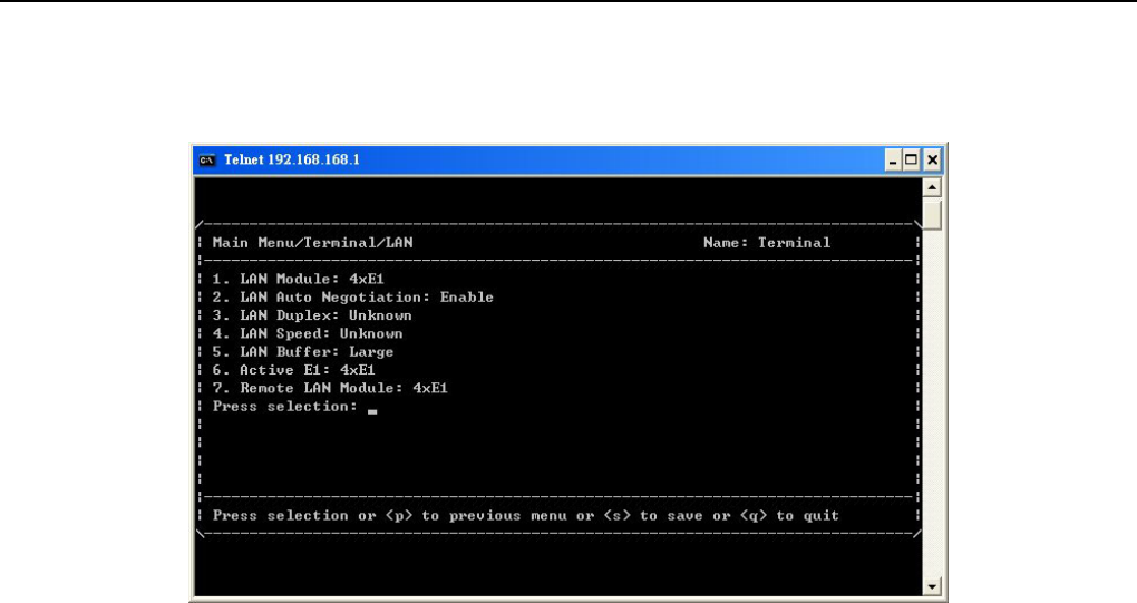
8.2.7 LAN
Figure 8-22 LAN
This subpage allows you to set the configurations of LAN. (This subpage displays with only E1+LAN product)
LAN Module: Activate E1 interface number which should be used for Ethernet transmission. Following items is
for option:Disable/1E1/2E1/3E1/4E1. When it is disabled, LAN function is closed and link LED light is off. If it
set to be 1E1/2E1/3E1/4E1, system will transfer E1 to Ethernet transmission.
9 If you choose 1E1, system would transfer last E1 to Ethernet transmission. If 2E1, system would transfer
last two E1 to Ethernet transmission and so on.
LAN Auto Negotiation: Activate/close Ethernet auto-negotiation function.
LAN Duplex: The configuration of Ethernet interface duplex.
LAN Speed: The configuration of Ethernet interface speed.
LAN Buffer: The configuration of Ethernet interface buffer.
Active E1: Display actual E1 interface number which has been transferred to Ethernet transmission.
9 If the configured interface number is different, the smaller number would be set to transmit.
Remote LAN Module: Display remote LAN interface status.
Textmenu Details
E1 Spread Spectrum Radios
8-17
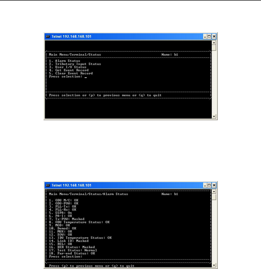
8.2.8 Status
Figure 8-23 Status
This page shows current status of alarm record, tributary, user I/O and retrieves event record. There are 5
subpages below:
8.2.9 Alarm Status
Figure 8-24 Alarm Status
This subpage shows the status of all the alarm items.
Textmenu Details
E1 Spread Spectrum Radios
8-18
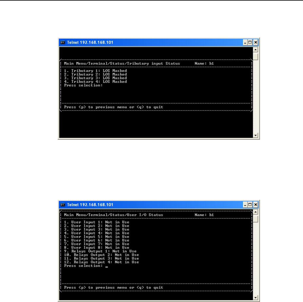
8.2.10 Tributary Input Status
Figure 8-25 Tributary Input Status
This subpage shows the tributary input signal status.
8.2.11 User I/O Status
Figure 8-26 User I/O Status
This subpage shows the User I/O interfaces status.
Textmenu Details
E1 Spread Spectrum Radios
8-19
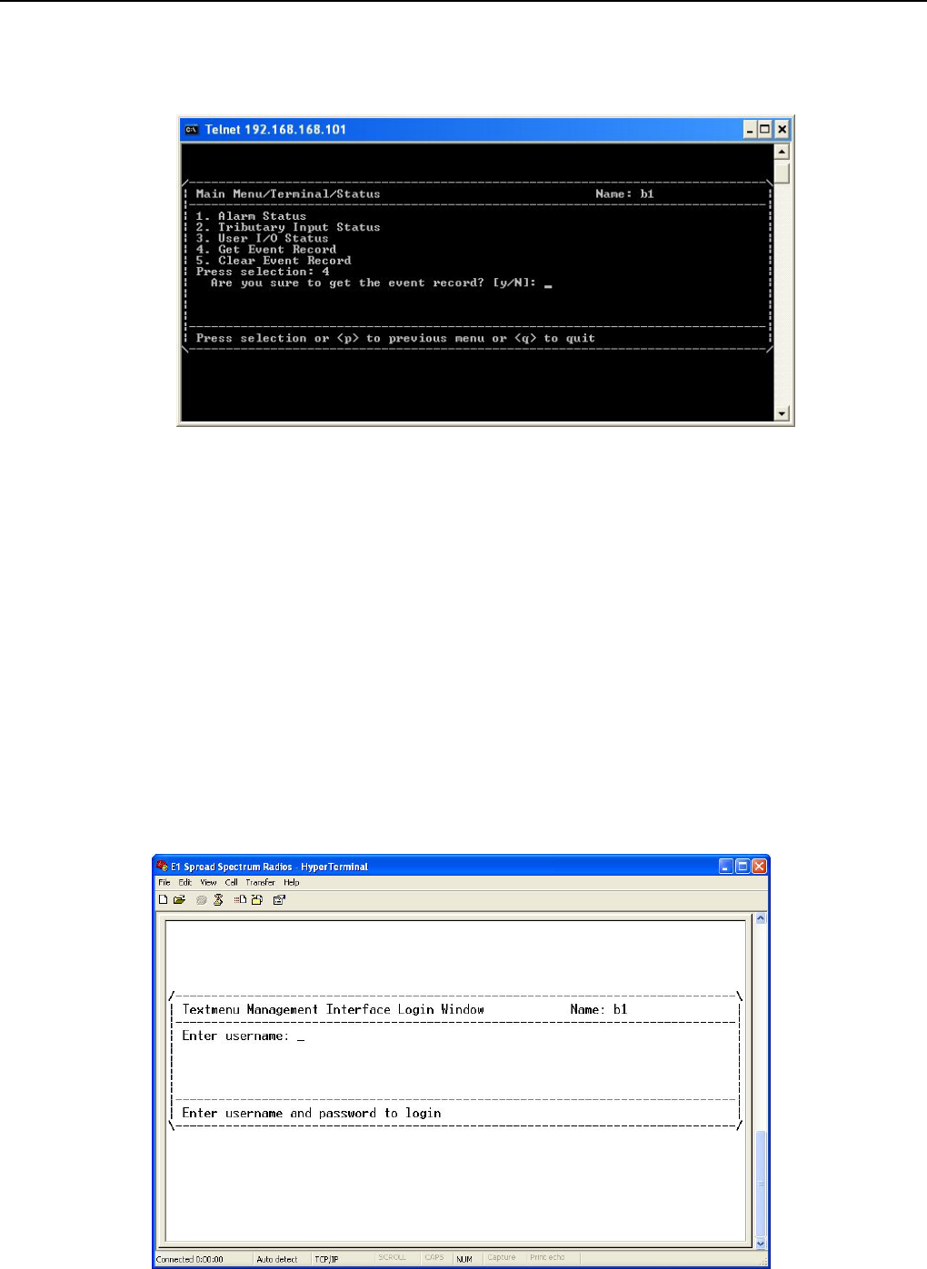
8.2.12 Get Event Record
Figure 8-27 Get Event Record
Alarm record could record up to 1000 items which save in IDU memory. It is compatible with G.826 protocol
and record for functionality of system.
The major parameter of error lists below:
(1)Error Second(ES):The second with one or more errors.
(2)Severe Error Second(SES): The second which error occupied more than 30% of the second.
(3)Background Block Error(BBE):The second which deducts total seconds from error of SES.
(4)Unavailable Second(UAS): Continuous 10 SES is the start of UAS which 10 SES have been defined to be
part ot UAS.
The method is as follows:
STEP1: Proceed to HyperTerminal under windows, and from HyperTerminal can further reach login windows.
Then login by the account you wish.
Textmenu Details
E1 Spread Spectrum Radios
8-20
Figure 8-28 Get Event Record(1)
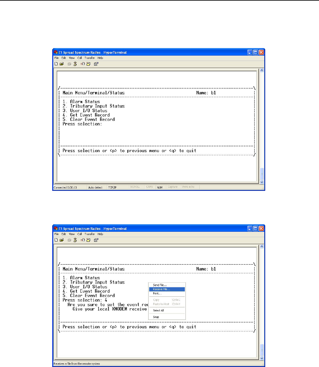
STEP2: Proceed with the login windows as above, then activate Get Event Record item.
Figure 8-29 Get Event Record(2)
STEP3: Right click the mouse and it will show the menu. Choose the “Receive File…”.
Figure 8-30 Get Event Record(3)
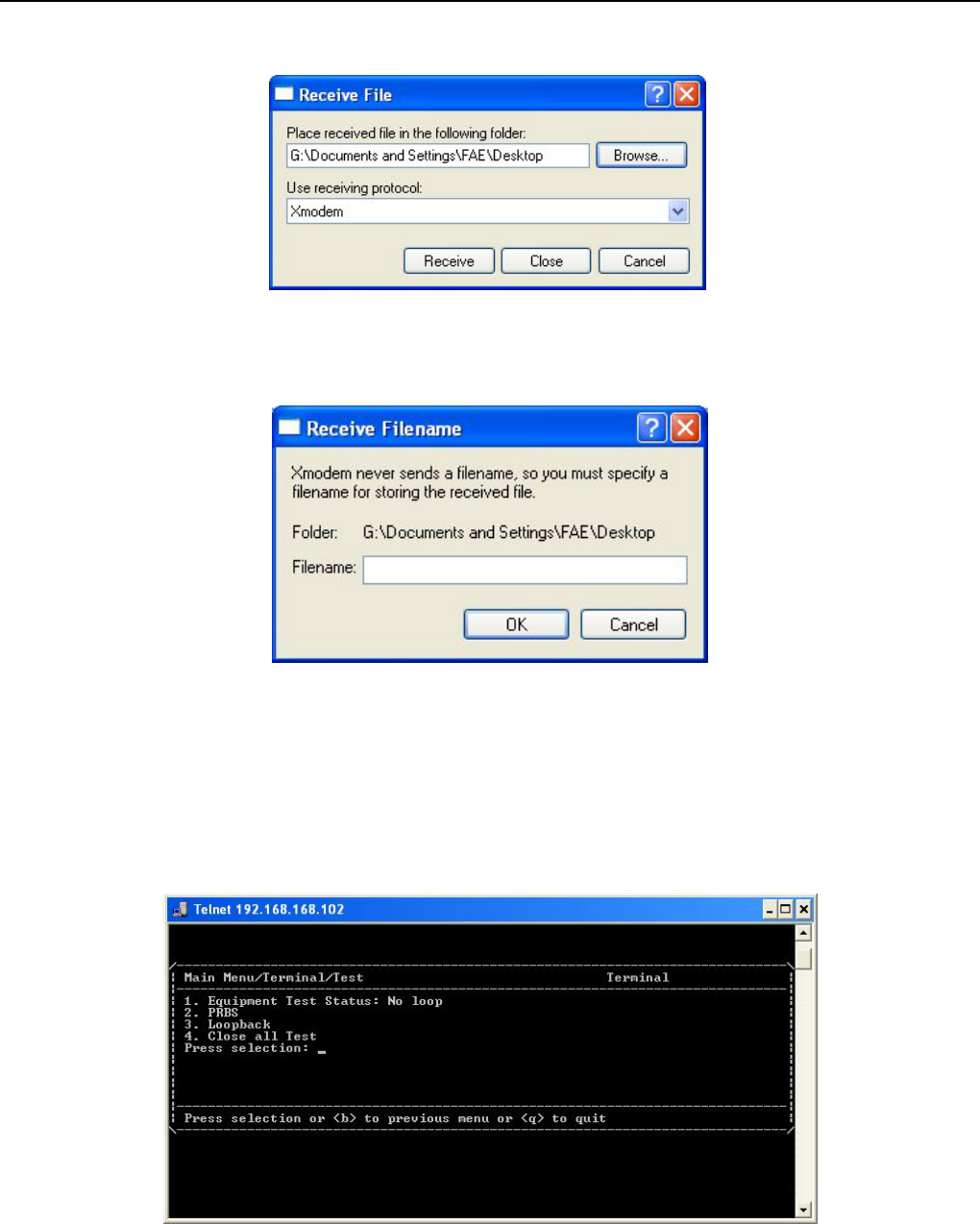
STEP4: Fill in the received file path and choose the receiving protocol to be “Xmodem”.
Textmenu Details
E1 Spread Spectrum Radios
8-21
Figure 8-31 Get Event Record(4)
STEP5: Fill in the receive filename and press “OK”. The procedure will be finished.
Figure 8-32 Get Event Record(5)
9 The received file would be in the format of txt file.
8.2.13 Test
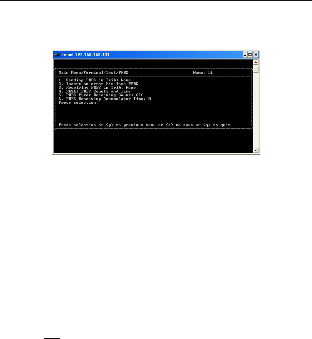
Figure 8-33 Test
This subpage displays all the loopback test items.
Equipment Test Status: This item shows current equipment status. If the status is “Test”, you could disable all
Textmenu Details
E1 Spread Spectrum Radios
8-22
test operations via implementing item “Close All Test”.
8.2.14 PRBS
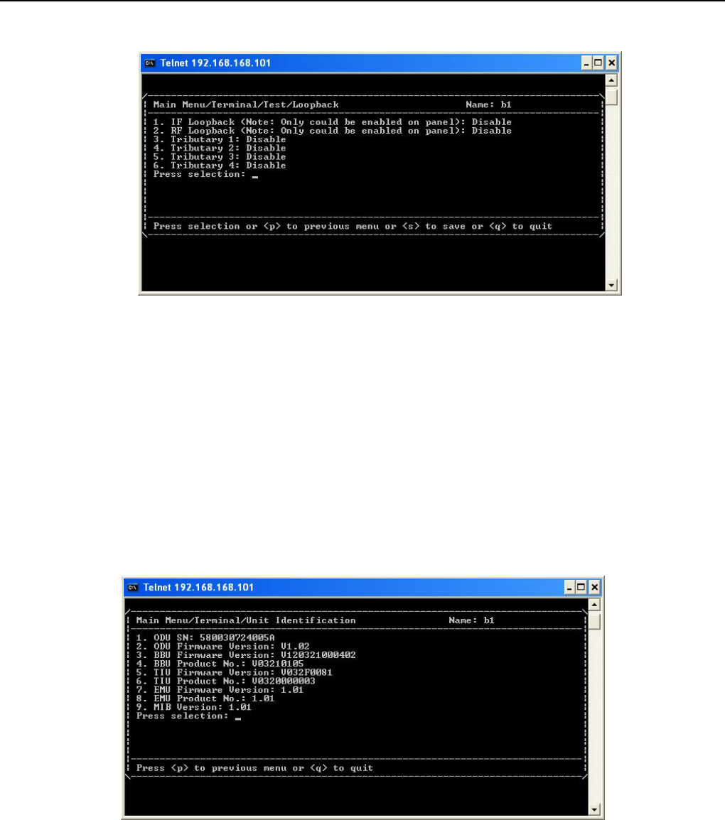
Figure 8-34 PRBS
PRBS: This item enables you to configure PRBS test operations.
9 Under normal working condition, other than the normal BER test, the PRBS function can be used as well
to test the individual link accumulated BER and stability of the system. While detecting, it is required to
start the PRBS function. This function setting is done through the textmenu or the LCD display button.
PRBS/Sending PRBS in Trib: This item allows you to set the tributary that you wish to send PRBS.
PRBS/Insert an error bit into PRBS: Once you have set the tributary of PRBS, you could select this item to
insert an error.
PRBS/Receiving PRBS in Trib: This item allows you to set the tributary that you wish to receive PRBS.
PRBS/RESET PRBS Counts and Time: This item allows you to reset the time and counts that receive PRBS.
PRBS/PRBS Error Receiving Count: This item shows the count number of receiving PRBS errors.
PRBS/PRBS Receiving Accumulator Time: This item shows the time of PRBS Receiving Accumulator.
Note: PRBS test explanation: Please refer to C.3 of chapter 5.
Textmenu Details
E1 Spread Spectrum Radios
8-23
Figure 8-35 Loopback
Loopback: This item enables you to configure loopback tests such as RF, IF, Local, Remote loopback tests.
9 IF and RF loopback only could be activated on panel and here shows the status of these two loopback
tests.
Close All Test: Disable all the running tests.
8.2.15 Unit Identification
Figure 8-36 Unit Identification
This subpage will display hardware and software version or serial number of system components.
Textmenu Details
E1 Spread Spectrum Radios
8-24
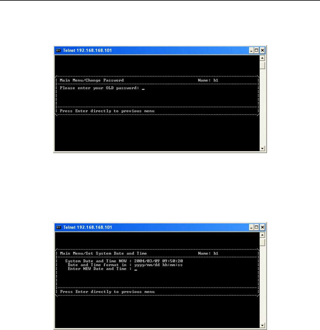
8.3 Change Password
Figure 8-37 Change Password
In this page, you could modify password of account which you have login.
8.4 Set System Date and Time
Figure 8-38 Set System Date and time
Configure the system date and time.
Textmenu Details
E1 Spread Spectrum Radios
8-25
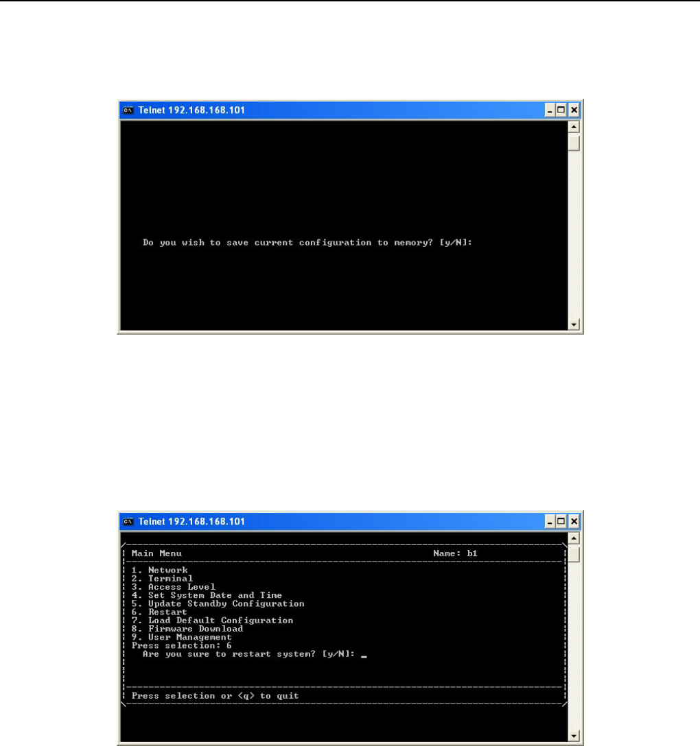
8.5 Update Standby Configuration
Figure 8-39 Update Standby Configuration
This item is to write configuration into system flash. If this action is not implemented, you will lose you
configuration after you restart system. This item is only for network setting.
8.6 Restart
Figure 8-40 Restart
In this page, you could restart the system. During restart process, E1 and data communication operation will
not be influenced. Any change or setup of items in the network pages should be restart to take configuration
into effect.
9 In the process of restarting, E1 and data transmission would not be affected.
Textmenu Details
E1 Spread Spectrum Radios
8-26
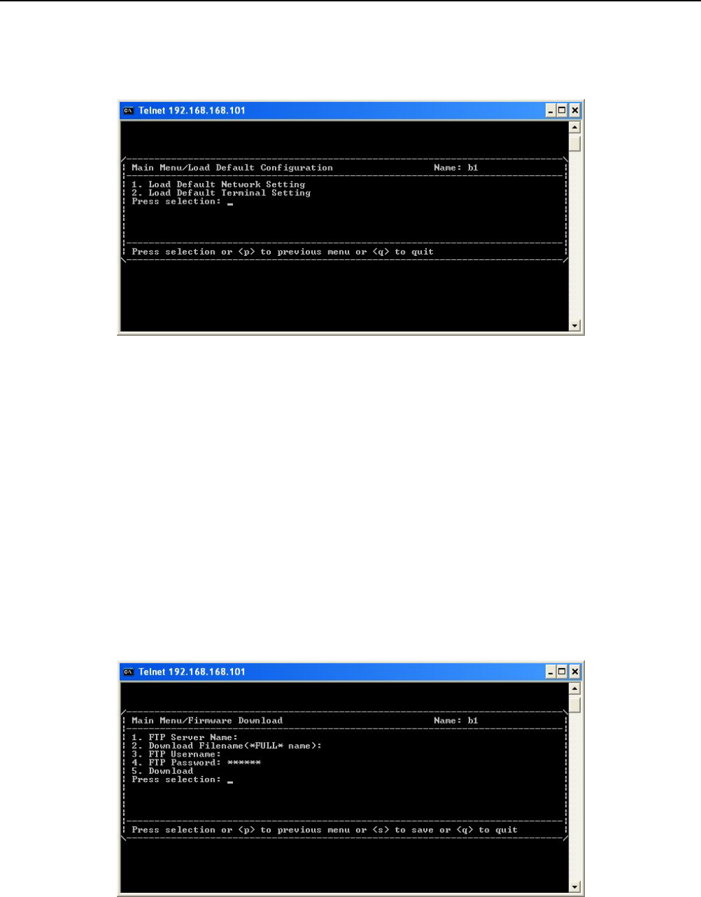
8.7 Load Default Configuration
Figure 8-41 Load Default Configuration
This page allows only superuser to access. In this page, there are two options:
Load Default Network Setting: This item would load network portion of default setting. When new firmware
first executes, you need to implement this item.
9 All the configurations including IP addresses and IP routes will disappear except that ETH IP address will
return to default value of 192.168.168.1.
Load Default Terminal Setting: This item would load terminal portion of default setting.
8.8 Firmware Download
Figure 8-42 Firmware Download
This page allows only superuser to access.In this page, you could implement download of firmware.
Textmenu Details
E1 Spread Spectrum Radios
8-27
FTP Server Name: The IP of FTP server.
Download Filename(*FULL* Name): The name which has to be downloaded.
FTP Username: Set the name of FTP server account.
FTP Password: Set the password of FTP server account.
Download: After you setup all necessary items above, select this item to download.
9 When you in the process of download, please DO NOT close the windows of download page and turn off
or restart the modem. These actions would result in crash of system. If system crashes, please contact
with us.
If finishing download, you need to restart the system to take new software into effective. After you restart, you
have to implement “Load Default Configuration/Load Default Network Setting” to load the new software
downloaded. Or software will not work properly.
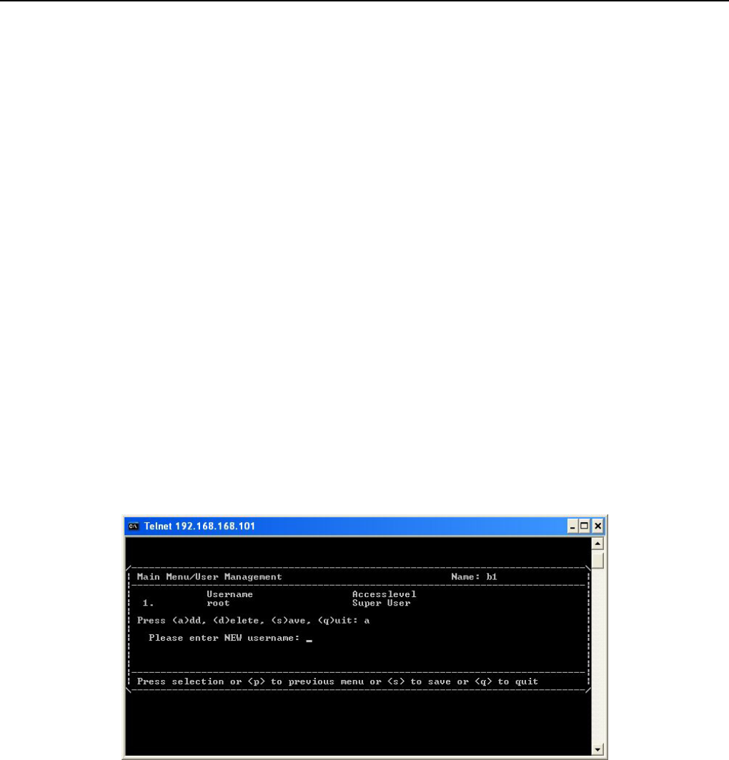
8.9 User Management
Figure 8-43 User Management
This page allows only superuser to access.In this page, you could manage login account. Login account level
has been classified into “Super User”, ”User”, and ”Operator”. The accounts which have been classified into
“Super User” have the highest priority and could implement all operations in the textmenu. If customer wants to
change its account name, be sure to add a new super user account and then delete old account. The accounts
which have been classified into “User” have permission to query. The accounts which have been classified into
“Operator” have permission to setup or change items except for pages of “User Management”, “Load Default

Textmenu Details
E1 Spread Spectrum Radios
8-28
Configuration”, and “Software Download”.
9 If there is no super user account exists, you would incapable of accessing the textmenu.
Management Application Structure
E1 Spread Spectrum Radios
9-1
9 Management Application Structure
IDU is an embedded system with routing function. It provides various managerial interfaces and abundant
method for management which is convenient for remote access. This chapter introduces how to deploy
network topology.
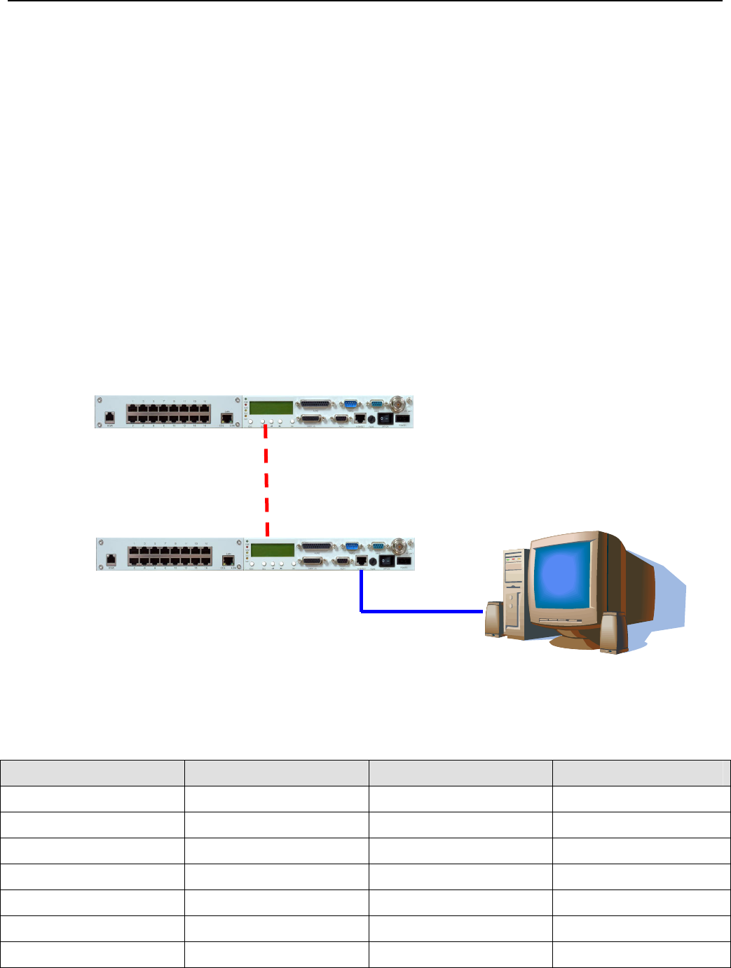
9.1 Managment via Local Equipment(Normal)
The following diagram is most popular in topology. The rest of the diagrams skip ODU and take IDU as the
whole system.
9 You should connect computer and ETH interface via cross-over cable.
Figure 9-1 Managment via Local Equipment(Normal)
Relative configuration parameters list below:
Table 9-1 Example for managerial application(1)
Item Modem 1 Modem 2 Note
ETH(10BaseT) IP 192.168.168.1 192.168.100.1 Refer to section 8.1.5
ETH(10BaseT) Mask 255.255.255.0 255.255.255.0 Refer to section 8.1.5
Link Data Rate 19200 19200 Refer to section 8.1.4
Link Usage Master Modem Slave Modem Refer to section 8.1.4
Link Local IP 10.0.0.1 10.0.0.2 Refer to section 8.1.4
Link Peer IP 10.0.0.2 10.0.0.1 Refer to section 8.1.4
Link Interface Activation Enable Enable Refer to section 8.1.4
ETH
RF Link Connection
Computer for monitor
Modem 1
Modem 2
Management Application Structure
E1 Spread Spectrum Radios
9-2
IP Forwarding Forwarding Forwarding Refer to section 8.1.7
IP Route Destination 192.168.100.0 Refer to section 8.1.8
IP Route Subnet Mask 255.255.255.0 Refer to section 8.1.8
IP Route Interface Link Refer to section 8.1.8
IP Route Gateway 10.0.0.2 Refer to section 8.1.8
Default Gateway
Interface
Ethernet Link Refer to section 8.1.8
Default Gateway 192.168.168.100 10.0.0.1 Refer to section 8.1.8
Trap/Trap Alarm Setting All All Refer to section 8.1.9
Trap/Destination 192.168.168.100 192.168.168.100 Refer to section 8.1.9
Trap/Community Private private Refer to section 8.1.9
Item Computer Note
IP 192.168.168.100 The same subnet with
modem 1
Subnet Mask 255.255.255.0
Default Gateway 192.168.168.1
Route add 192.168.100.0 mask 255.255.255.0 192.168.168.1
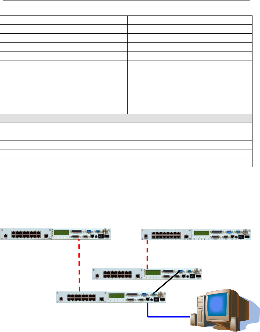
9.2 Managment via Local Equipment(Cascading)
The following diagram is cascading mode. Multiple systems should interconnect NMS2-NMS1 with RS-232
cable to communicate all the monitor signals.
NMS2
NMS1
ETH
RF Link Connection
Computer for monitor
Modem 1
Modem 2
Management Application Structure
E1 Spread Spectrum Radios
9-3
Figure 9-2 Managment via Local Equipment(Cascading)
Please refer to example 1 for configuration of Point-to-Point. This example focuses on configuration of
cascading.
Table 9-2 Example for managerial application(2)
Item Modem 1 Modem 2 Note
ETH(10BaseT) IP 192.168.168.1 192.168.100.1 Refer to section 8.1.5
ETH(10BaseT) Mask 255.255.255.0 255.255.255.0 Refer to section 8.1.5
NMS2 Data Rate 115200 N/A Refer to section 8.1.2
NMS2 Usage Master Modem N/A Refer to section 8.1.2
NMS2 Local IP 10.0.0.1 N/A Refer to section 8.1.2
NMS2 Peer IP 10.0.0.2 N/A Refer to section 8.1.2
NMS2 Interface
Activation
Enable N/A Refer to section 8.1.2
NMS1 Data Rate N/A 19200 Refer to section 8.1.1
NMS1 Usage N/A Slave Modem Refer to section 8.1.1
NMS1 Local IP N/A 10.0.0.2 Refer to section 8.1.1
NMS1 Peer IP N/A 10.0.0.1 Refer to section 8.1.1
NMS1 Interface
Activation
N/A Enable Refer to section 8.1.1
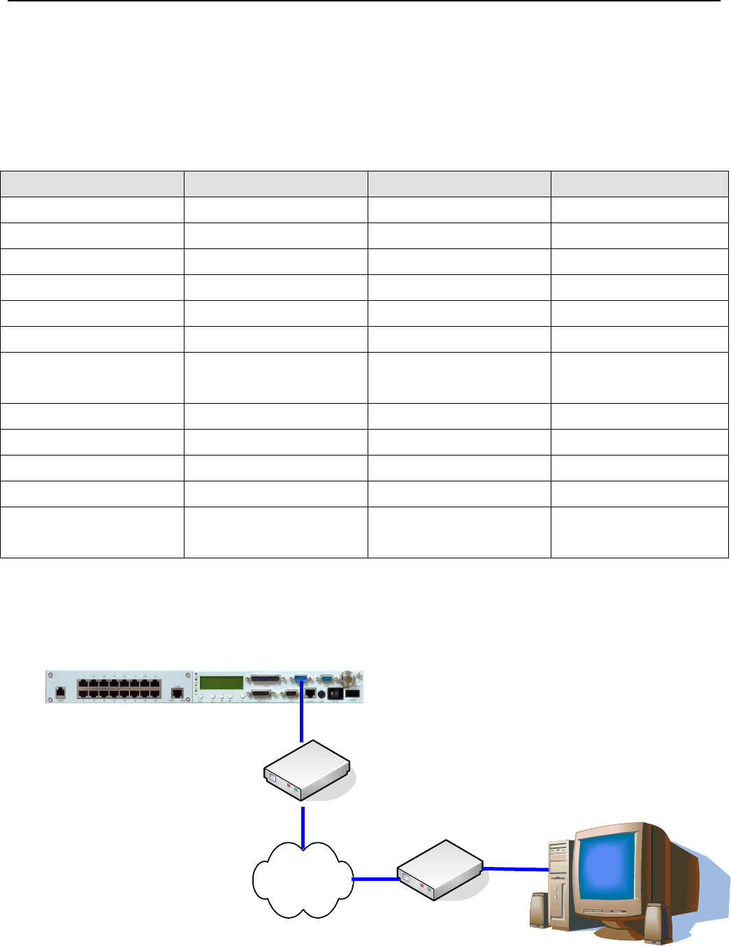
9.3 Remote Management via External Modem
The following shows how to remote manage via external modem.
NMS2
Computer for monitor
Dialup Modem
PSTN
Dialup Modem
Modem 1

Management Application Structure
E1 Spread Spectrum Radios
9-4
Figure 9-3 Remote Management via External Modem
Please refer to example 1 for configuration of Point-to-Point. This example focuses on configuration of external
modem.
Table 9-3 Example for managerial application(3)
Item Modem 1 Note
ETH(10BaseT) IP 192.168.168.1 Refer to section 8.1.5
ETH(10BaseT) Mask 255.255.255.0 Refer to section 8.1.5
NMS2 Data Rate 115200 Refer to section 8.1.2
NMS2 Usage External Wired Modem Refer to section 8.1.2
NMS2 Local IP N/A Refer to section 8.1.2
NMS2 Peer IP N/A Refer to section 8.1.2
NMS2 Interface
Activation
Enable Refer to section 8.1.2
Model Mode Dial Out at Once Refer to section 8.1.3
Telephone Number for
Outgoing Call
PSTN Telephone Number Refer to section 8.1.3
Username N/A Refer to section 8.1.3
Modem Authentication
Protocol
N/A Refer to section 8.1.3
PAP Password N/A Refer to section 8.1.3
CHAP Password N/A Refer to section 8.1.3

Appendices
E1 Spread Spectrum Radios
10-1
10 Appendices
10.1 Specifications
Table 10-1 Transmitter& Receiver
Operation Frequency 5725~5850MHz
Communication Mode Frequency Division Duplex, FDD
Modulation QPSK
TX Output Power < 22dBm
RX Dynamic Range -84dBm ~ -15dBm
5.8GHz
2E1 < -89dBm
4E1 < -86dBm
8E1 < -83dBm
Sensitivity (10-3 BER)
16E1 < -80dBm
2E1 < -87dBm
4E1 < -84dBm
8E1 < -81dBm
Sensitivity (10-6 BER)
16E1 < -77.5dBm
2E1 8 Channel
4E1 4 Channel
8E1 2 Channel
Frequency Selection
16E1 1 Channel
BER During Normal Propagation < 10 -10
Receiver Max Input < -10dBm
Receiver Max Input with no BER < -15dBm
Frequency Stability +10ppm
Gain Flatness (anywhere) RX: + 1 dB TX: + 1dB
TX & RX Isolation 60dB
TVS > 40 kilovolts
RSSI (BNC) for Antenna Alignment
Table 10-2 Digital Line Interface
Data Rate 2,048 Mbps
E1 Connector (ITU-T G.703) BNC Unbalanced, 75 ohm

Appendices
E1 Spread Spectrum Radios
10-2
or
RJ-48, 120 ohm
Signal BER LCD Display on IDU
Table 10-3 IDU Structure
IDU LCD Display of IDU, ODU, Remote, Alarm, Test Item
Information
Alarm Buzzer, LED Indication, LCD Display
FINE IDU Status
ALM Alarm Condition
TEST Test Condition
LED Indication
RMT Remote Status
Table 10-4 Temperature and Environment
Operating Temperature Range IDU:-5 to 55 ℃
ODU:-30 to 60 ℃
Humidity IDU:10%~95% Non-condensing
ODU:0%~100%
Altitude 5,000 meters (maximum)
Table 10-5 Network Management System
Operating Method HyperTerminal/Telnet
Interface 10/100BaseT
Protocol Telnet, SNMPv1,SNMPv2,MIB
Table 10-6 IF Cable
Link Cable < 100M RG-6
< 200M RG-8
Frequency 70MHz
Stability ±50ppm
Power -35dBm~-5dBm
IDU INPUT
Return Loss VSWR≦ 1.3
IDU OUTPUT Frequency 310MHz

Appendices
E1 Spread Spectrum Radios
10-3
Stability ±50ppm
Power -4dBm±2dBm
Return Loss VSWR≦1.3
Frequency 11.0592MHz
Stability ±50ppm
Power 150~180mVpp
Monitoring Signal
Return Loss VSWR ≦ 1.3
Table 10-7 Power
DC Input -48VDC (-36~ -72V)
Power Consumption < 45 watts
AC Input (optional) 100-240VAC 50-60Hz
Connector Barrier strip, plug-in type
Table 10-8 Service Channel
Frequency 300-3400Hz
Impedance 600 ohm balance
Telephone
Interface RJ-11
Bit Rate ≦9600 baud
Protocol RS-232
Monitoring Data
(NMS1)
Interface DB-9(Female)
Bit Rate ≦9600 baud
Protocol RS-232
Monitoring Data
(NMS2)
Interface DB-9(Male)
Bit Rate ≦9600 baud
Protocol RS-232
Computer Data
(AUX1)
Interface DB-9(Female)
Bit Rate ≦9600 baud
Protocol RS-232
Computer Data
(AUX2)
Interface DB-25(Female)
Type Photo-coupled (TTL)
Interface DB-26(Female)
Number 8
Isolation 3000 VAC(rms)
User Input
LED Power Dissipation 90 mW

Appendices
E1 Spread Spectrum Radios
10-4
Type Relay output
Interface DB-26(Female)
Number 4
Max. switching voltage 125VAC / 60VDC
User Output
Max. switching current 1A

Appendices
E1 Spread Spectrum Radios
10-5
10.2 LCD Alarm Items
Table 10-9 LCD Alarm Items
Alarm Grade Status Explanation
MOD Critical Modulation alarm Modulation malfunctions
DEMOD Critical Demodulation lock failure Demodulation signal loss
EOW Major No service between equipments Incorrect connection data
ODU-POW Critical The -48V power supply of IDU malfunctions The cable between IDU & ODU is
short
Link ID Major LINK ID at the remote end is different from
the user’s setting
MUX Critical Receiving lock failure Even bridging cannot lock the timing
I n-LOS Warning IDU cannot detect the input tributary signal No Traffic input parameters
I n- AIS Warning Tributary signal input are all 1’s Traffic input parameters are all 1’s
ODU- M/C Major IDU cannot monitor ODU M&C channel between IDU and
ODU is down
RSL Major Receive signal level alarm Rx connection is not on the best
situation
BER Major Bit error rate alarm Connection is not on the best
situation
-5V Critical ODU -5V power alarm
SSPA Major Solid state power amplifier is off
TX-POW Major Tx is out of range Transmitter is abnormal
PLL-TX Critical Tx of ODU phase lock LO lose lock
PLL-RX Critical Rx of ODU phase lock LO lose lock
PA-I Critical The current is out of range SSPA is abnormal

Appendices
E1 Spread Spectrum Radios
10-6
10.3 LCD Function
Table 10-10 LCD Function
Status LCD Display Function Description
1 EOW No.: n Display the service number Display the local equipment’s service phone
number
2 IDU Type: nXE1 Display the activity measure Display the number of E1 equipments
3 Code: AMI/HDB3 Display or set the model
number
Display or set the E1 equipments model
number
4 AUX1: RS-232/RS-422 Display or set the protocol Display the selected protocol
5 AUX2: ASY-CH/SYN-CH Display or set the transmission
methodology Display the transmission method
6 I-Temp: n℃ IDU working temperature IDU working temperature
7 Buzzer: On/Off Buzzer switch Buzzer switch
8 Restart EMU:Y/N Restart E1 radios system Set the configuration via LCD and textmenu
IDU
Info
9 Power: -36~-72V Display input power Display input power
1 RF-CH Display RF channel Display the present ODU RF channel
2 TxL-SET: n dBm Display the transmit power Display the transmit power, n =
10~22dBm
3 SSPA: On/Off Set the PA to ON/OFF Set the PA to ON/OFF
ODU
Info
4 O-Temp: n℃ ODU working temperature ODU working temperature
1 Tri-Loc-Loop Tn-L-Lp:
En/Dis Set Local Loopback
Perform loopback test in the local end for
the convenience of testing the local end
equipment’s stability
2 Tri-Rem-Loop Tn-R-Lp:
En/Dis Set Remote Loopback
Perform loopback test in the remote end for
the convenience of testing the link system
stability
3 Tri-TX-PRBS Tn-PRBS:
En/Dis BER test Use Pseudo Random Code to test the E1
signal transmission
4 Ber-Clear: Clear all accumulated Ber Clear all accumulated Ber on starting the
Ber test
5 Count-Add: Display all accumulated BER Display all currently accumulated BER on
starting the Ber test
Test
Item
6 P-Acc-T:nS Display all accumulated BER
time
Display all currently accumulated BER
when start loopback test

Appendices
E1 Spread Spectrum Radios
10-7
7 IF-Loop: En/Dis Set IF Loopback
Perform loopback test from IF interface for
the convenience of testing the IDU’s
stability
8 RF-Loop: En/Dis Set RF Loopback
Perform loopback test from RF interface for
the convenience of testing the IDU’s
stability
9 Close-Test: Y/N Close all test Y: close N: cancel
1 Link ID: n Display the remote link ID Display the link ID of the remote equipment;
n=1~255
2 Far-end OK/Loss Display the connection status
of remote end
OK: in connection
Loss: remote monitor function lost
3 R-AUX1:
RS-232/RS-422 Display remote AUX1 status Display remote AUX1 status
Remote
Info
4 R-AUX2:
ASY-CH/SYN-CH Display remote AUX2 status Display remote AUX2 status
1 ETH IP: Display ETH port IP address Set the configuration via textmenu
2 ETH Mask: Display ETH port subnet mask Set the configuration via textmenu
3 NMS1 IP: Display NMS1 port IP address
Set the configuration via textmenu, and
manifest when PPP connection are
established
4 NMS1 Peer IP:
Display peer NMS1 port IP
address when more than two
equipments are connected in
the local station
Set the configuration via textmenu, and
manifest when PPP connection are
established
5 NMS2 IP: Display NMS2 IP address
Set the configuration via textmenu, and
manifest when PPP connection are
established
6 NMS2 Peer IP:
Display peer NMS2 port IP
address when more than two
equipments are connected in
the local station
Set the configuration via textmenu, and
manifest when PPP connection are
established
IP Info
7 Link IP:
Display Link port IP address.
Link means RF connection
between two stations
Set the configuration via textmenu, and
manifest when PPP connection are
established

Appendices
E1 Spread Spectrum Radios
10-8
8 Link Peer IP: Display peer Link port IP
address
Set the configuration via textmenu, and
manifest when PPP connection are
established
1 LAN-Port:
Dis/1E1/2E1/3E1/4E1
Activate E1 interface number
which should be used for
Ethernet transmission.
Set the configuration via LCD, textmenu,
and SNMP software
2 Actual: None/n E1
Display actual E1 interface
number which has been
transferred to Ethernet
transmission.
Set the configuration via LCD, textmenu,
and SNMP software
3 Auto-Nego: None/Dis/En Activate/close Ethernet
auto-negotiation function.
Set the configuration via LCD, textmenu,
and SNMP software
4 Duplex: None/Full/Half The configuration of Ethernet
interface duplex.
Set the configuration via LCD, textmenu,
and SNMP software
5 Speed: None/10M/100M The configuration of Ethernet
interface speed.
Set the configuration via LCD, textmenu,
and SNMP software
LAN Info
6 Buffer:
None/Small/Large
The configuration of Ethernet
interface buffer.
Set the configuration via LCD, textmenu,
and SNMP software
1 S-Test: Start/Testing Activate Self Test function/Self
Test status display
2 S-Test Result Self Test result displays
Self Test
Info
3 Close-Test Close Self Test function
1 Link ID:n Display and set the link ID Set the configuration via LCD, textmenu,
and SNMP software
Link
Info
2 MODEM: On/Off Display remote dialup modem
status
Display if any remote dialup modem is
connected or not

Appendices
E1 Spread Spectrum Radios
10-9
10.4 Spread Spectrum Plan
Table 10-11 5.8GHz Spread Spectrum List (16E1, Side A)
16E1
TX RX
Channel
Left Middle Right Left Middle Right
1 5816 5830 5844 5732 5746 5760
(Frequency Unit: MHz / QPSK)
Table 10-12 5.8GHz Spread Spectrum List (16E1, Side B)
16E1
TX RX
Channel
Left Middle Right Left Middle Right
1 5732 5746 5760 5816 5830 5844
(Frequency Unit: MHz / QPSK)
Appendices
E1 Spread Spectrum Radios
10-10
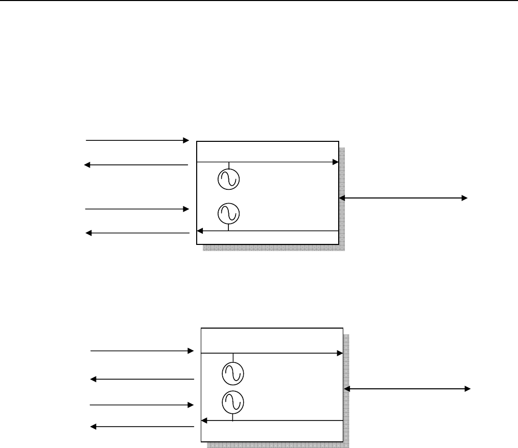
10.5 ODU IF & RF Status
10.5.1 5.8GHz Status
Figure 10-1 Side A IF & RF Status
Figure 10-2 Side B IF & RF Status
Tx: 5.814~5.846GHz
ODU Side A: RF Unit
Rx: 5.730~5762GHz
IF 310MHz
IF 70M
-48V/ 0.5A
Monitor 11.0592MHz
ODU Side B: RF Unit
Tx: 5.730~5.762GHz
Rx: 5.814~5.846GHz
IF 310MHz
IF 70M
-48V/ 0.5A
Monitor 11.0592MHz

Appendices
E1 Spread Spectrum Radios
10-11
10.6 The Definition of Pins
Table 10-13 DB9 female pins of NMS1
DB-9 Description
1
2 Transmitted data (OUTPUT)
3 Received data (INPUT)
4
5 GND
6
7 Request to send (INPUT)
8
9 NC
Table 10-14 DB9 male pins of NMS2
DB-9 Description
1 Received Line Signal Detector (INPUT)
2 Receive data (INPUT)
3 Transmit data (OUTPUT)
4
5 GND
6 DCE Ready (INPUT)
7
8
9 NC
Table 10-15 DB9 female pins of AUX1 (V.28)
DB-9 Description
1 NC
2 TXD (OUTPUT)
3 RXD (INPUT)
4
5 GND
6
7
8
9
Table 10-16 DB9 female pins of AUX1 (V.11)

Appendices
E1 Spread Spectrum Radios
10-12
DB-9 Description
1 NC
2 TXD- (OUTPUT)
3 RXD+ (INPUT)
4
5 GND
6
7 TXD+ (OUTPUT)
8 RXD- (INPUT)
9
Table 10-17 DB26 pins of USER I/O
DB-26 Description
1 Input 3
2 GND
3 Input 4
4 Output 1C
5 Output 1NC
6 Output 1NO
7 Output 3C
8 Output 3NC
9 Output 3NO
10 Input 2
11 Input 5K
12 Input 5A
13 Input 6K
14 Input 6A
15 Input 7K
16 Input 7A
17 Input 8K
18 Input 8A
19 GND
20 Input 1
21 Output 4NO
22 Output 4NC
23 Output 4C
24 Output 2NO
25 Output 2NC
26 Output 2C
Table 10-18 DB25 pins of AUX2
DB-25 Description
1 GND

Appendices
E1 Spread Spectrum Radios
10-13
2 TX+ (OUTPUT)transmit data+
3 RX+ (INPUT) receive data+
4
5
6
7 GND
8
9 RC- (OUTPUT) receive clock-
10
11
12 TC- (OUTPUT) transmit clock-
13
14 TX- (OUTPUT) transmit data-
15 TC+ (OUTPUT) transmit clock
16 RX- (INPUT) receive data-
17 RC+ (OUTPUT) receive clock+
18
19
20
21
22
23
24
25
Table 10-19 Balanced E1 Interface(RJ-48)
RJ-48 Description Direction
1 RX TIP Input
2 RX Ring Input
3 RX Shield
4 TX TIP Output
5 TX Ring Output
6 TX Shield
7
8

Appendices
E1 Spread Spectrum Radios
10-14
10.7 Installation Guide
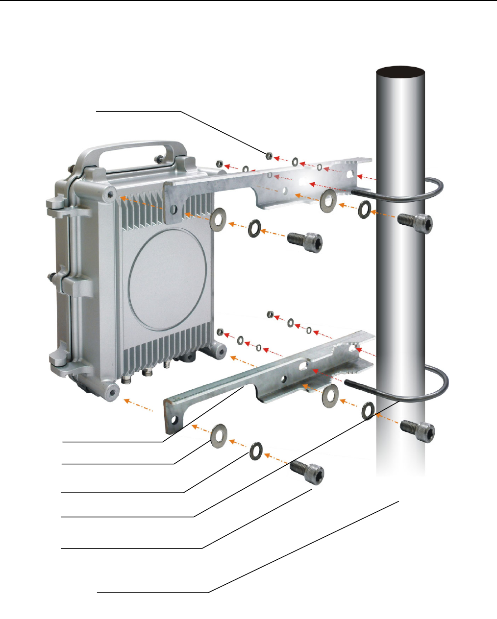
10.7.1 Parts of ODU assembly
Nut[1] Split Washer[2] Flat Washer[3] Hex Screw[4]
ODU Fastening Assembly
Figure 10-3 Part accessories
Part Q’TY
Nut[1] 4
Split Washer[2] 8
Flat Washer[3] 8
Hex Screw[4] 4
Mounting Bracket[5] 2
U-Bracket[6] 2
Mounting Bracket [5]
U-Bracket[6]
Appendices
E1 Spread Spectrum Radios
10-15
10.7.2 ODU Installation Diagram
Figure 10-4 ODU Installation Diagram
1
2
3
4
5
6
ODU Mast
Appendices
E1 Spread Spectrum Radios
10-16
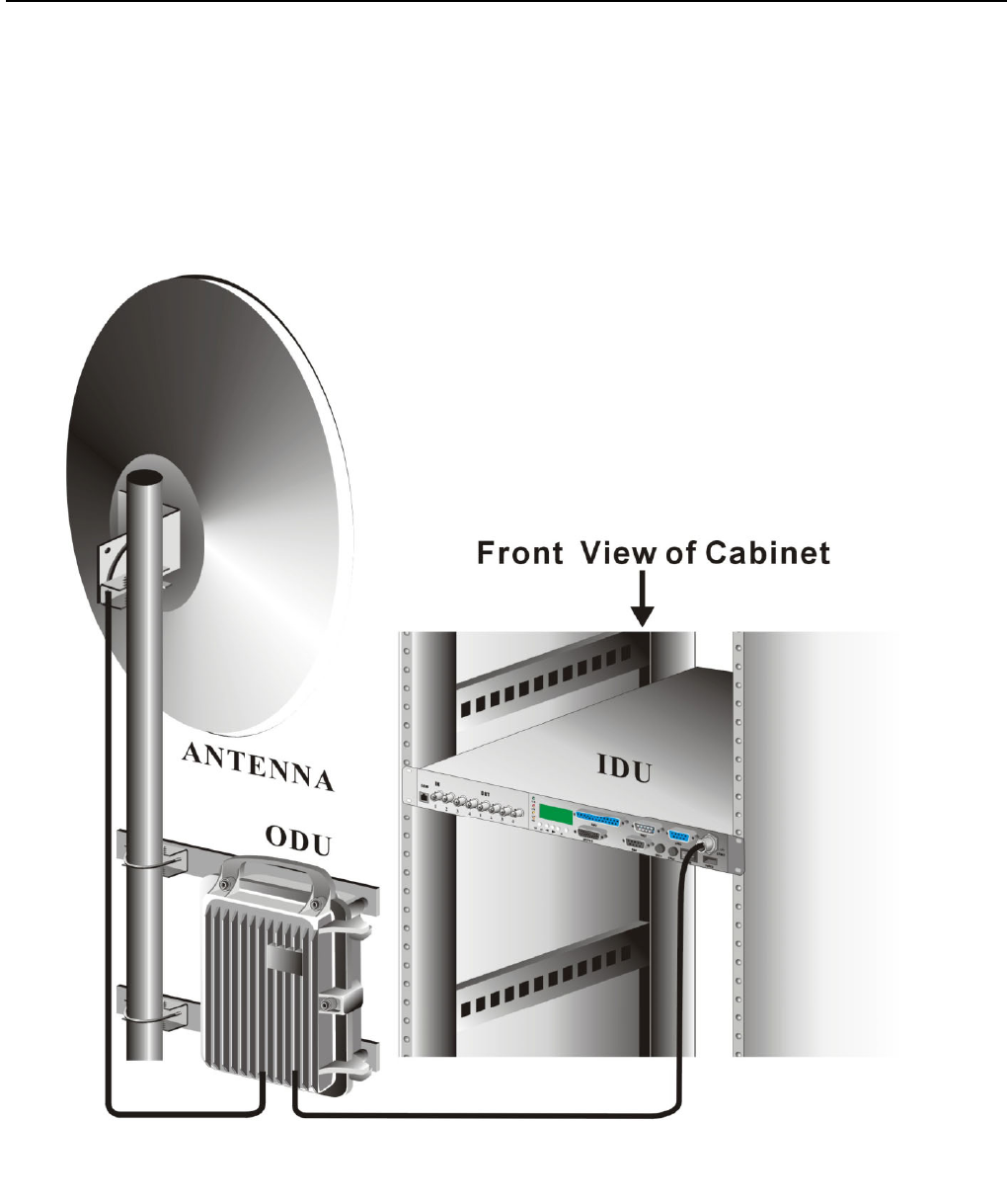
10.7.3 IDU+ODU Quick Installation
For RJ-48/BNC Type
Figure 10-5 IDU & ODU Connection Diagram
Appendices
E1 Spread Spectrum Radios
10-17
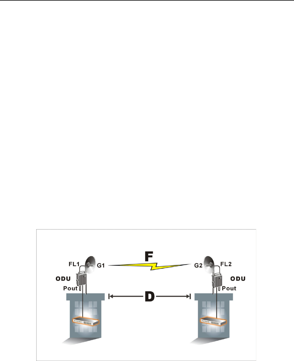
10.8 RSL and Link Budget
The received signal level (RSL) can be estimated using the following formula:
RSL (dBm) = Pout – FL1 + G1 + G2 – FL2 – LP
Link budget or SOM (dBm) = RSL – Sensitivity of system
where: Pout is the transmitter output power (in dBm)
FL1 is the feeder loss of the transmit side (in dBm)
G1 is the gain of the transmit antenna (in dB)
G2 is the gain of the receive antenna (in dB)
FL2 is the feeder loss of the receive side (in dB)
LP is the Path loss, defined by:
LP (dB) = 96.6 + 20 log10F + 20 log10D
where: F = Frequency in GHz (1.5, 2.4 or 5.8)
D = Distance of path in km
This link budget is very important for determining any potential problems during installation. We suggest that
link budget should be more than 20dB and then the link status would be stable and transmission would be
perfect. If you have calculated the expected RSL, you can see if it has been achieved during installation, and
troubleshoot if necessary.
Figure 10-6 RSL and Link Budget

Appendices
E1 Spread Spectrum Radios
10-18
10.9 Troubleshooting
10.9.1 Can Not Establish a Link
If your E1 radios can’t link each other perfectly and display no green light on IDU, please find the following
steps for troubleshooting.
Step1: Check the physical connection from IDU to antenna of both sides if any connector is loosened or
improper connected. Please refer to section 10.7 for further information.
9 We suggest that the cable between IDU and ODU should be the one we attached in our package.
9 As for the signals come from the ODU are high frequency ones, we suggest customers use low-loss
high-frequency cable such as LMR-900 to maximize the distance between two sides.
Step2: Check the Rx LED on the ODU or Rx/Tx reading on the IDU. We suggest that if the Rx reading is lower
than -60dB, then it has great possibility that you encounter RF problem. You could take following measures in
order to verify the situation.
Step2.1: There is possibility of wrong antenna angle toward each other. Please adjust your antennas to
the correct angle.
Step2.2: There is possibility of air interference. Please switch your RF channel to another available one
of both sites.
Step3: Check the configuration. Please find the following configurations are correct or not by using whether
LCD panel or telnet utility.
Item Location of LCD Location of Textmenu Configurations
RF Channel ODU Info/RF-CH(Section
5.2.2)
Terminal/ODU(Section 8.2.1) This setting should be the
same as remote site.
Power of Tx ODU Info/TxL-SET(Section
5.2.2)
Terminal/ODU(Section 8.2.1) This setting should be set to
be maximum value such as
22.
SSPA ODU Info/SSPA(Section
5.2.2)
Terminal/ODU(Section 8.2.1) This setting should be set to
be ON.
Link ID Link Info/Link ID(Section
5.2.8)
Terminal/Link(Section 8.2.3) This setting should be the
same as remote site.
Step4: Please conduct loopback tests to verify if the system is broken or not by following order. Please refer to
section 5.2.3 and section 8.2.13 for detail operation. If any of the following items fails, then contact us to start
RMA procedure.

Appendices
E1 Spread Spectrum Radios
10-19
Step4.1: Perform IF loopback to check if IDU works well or not. If IF loopback is error-free, then IDU must
be ok.
Step4.2: Perform RF loopback to check if ODU works well or not. IF RF loopback is error-free, then ODU
must be ok.
Step4.3: Perform the same loopback on the other sites to check if the status of the other site.
Step5: If you have spare parts for system or antennas, try to replace equipment one by one to verify the
problem. If any of the equipments fails, then contact us to start RMA procedure.
Step6: Shorten the distance between two sites to about 500 meters or connect antenna port to each other with
physical cable and about 50 attenuation loss. This is to verify the system status in short distance. If the system
fails with this topology, then the antenna or RF cable must be defective.
Step7: Recalculate link budget by the method of section 10.8. If the link budget is lower than standard, then
please reduce the system loss or increase the gain of antenna.
10.9.2 Establish a Link but Poor Performance
If E1 radios display green light on the IDU but with lots of error occurred, please find the following steps for
troubleshooting.
Step1: Check the Rx LED on the ODU or Rx/Tx reading on the IDU. We suggest that if the Rx reading is lower
than -60dB, then it has great possibility that you encounter RF problem. You could take following measures in
order to verify the situation.
Step1.1: There is possibility of wrong antenna angel toward each other. Please adjust your antennas to
the correct angle.
Step1.2: There is possibility of air interference. Please switch your RF channel to another available one
of both sites.
Step1.3: There is possibility of poor link budget. Please reduce the system loss or increase the gain of
antenna.
Step2: Check if some loopback tests have been performed then.
Step3: Please conduct loopback tests to verify if the system is broken or not by following order. Please refer to
section 5.2.3 and section 8.2.13 for detail operation. If any of the following items fails, then contact us to start
RMA procedure.
Step3.1: Perform IF loopback to check if IDU works well or not. If IF loopback is error-free, then IDU must
be ok.
Step3.2: Perform RF loopback to check if ODU works well or not. IF RF loopback is error-free, then ODU
must be ok.
Step3.3: Perform the same loopback on the other sites to check if the status of the other site.

Appendices
E1 Spread Spectrum Radios
10-20
10.9.3 Pre-RMA and RMA Procedure Notification
Please see the following steps for pre-RMA and RMA procedure.
Step1: Contact with your sales person and ask for help by email or telephone.
9 Our technical support personnel will try our best to help you with the problems.
Step2: If the problem can’t solve by email or telephone, then inform your sales person with following
information. Then sales person would give you a return RMA number and address.
(1) The model number of the products.
(2) The S/N of the system such as IDU, ODU or any other equipment procured from us.
(3) The name of contact sales.
(4) The procured date.
(5) The detail problem you have encountered and what measures you have took to solve the situation.
Step3: Pack the product and the accessories properly and attached manifest RMA outside the carton. Then
send the package back to the return address.
Step4: Our sales person would update latest RMA schedule to you.