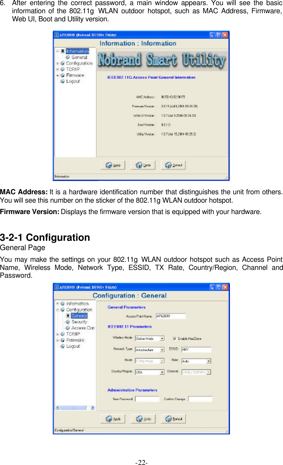
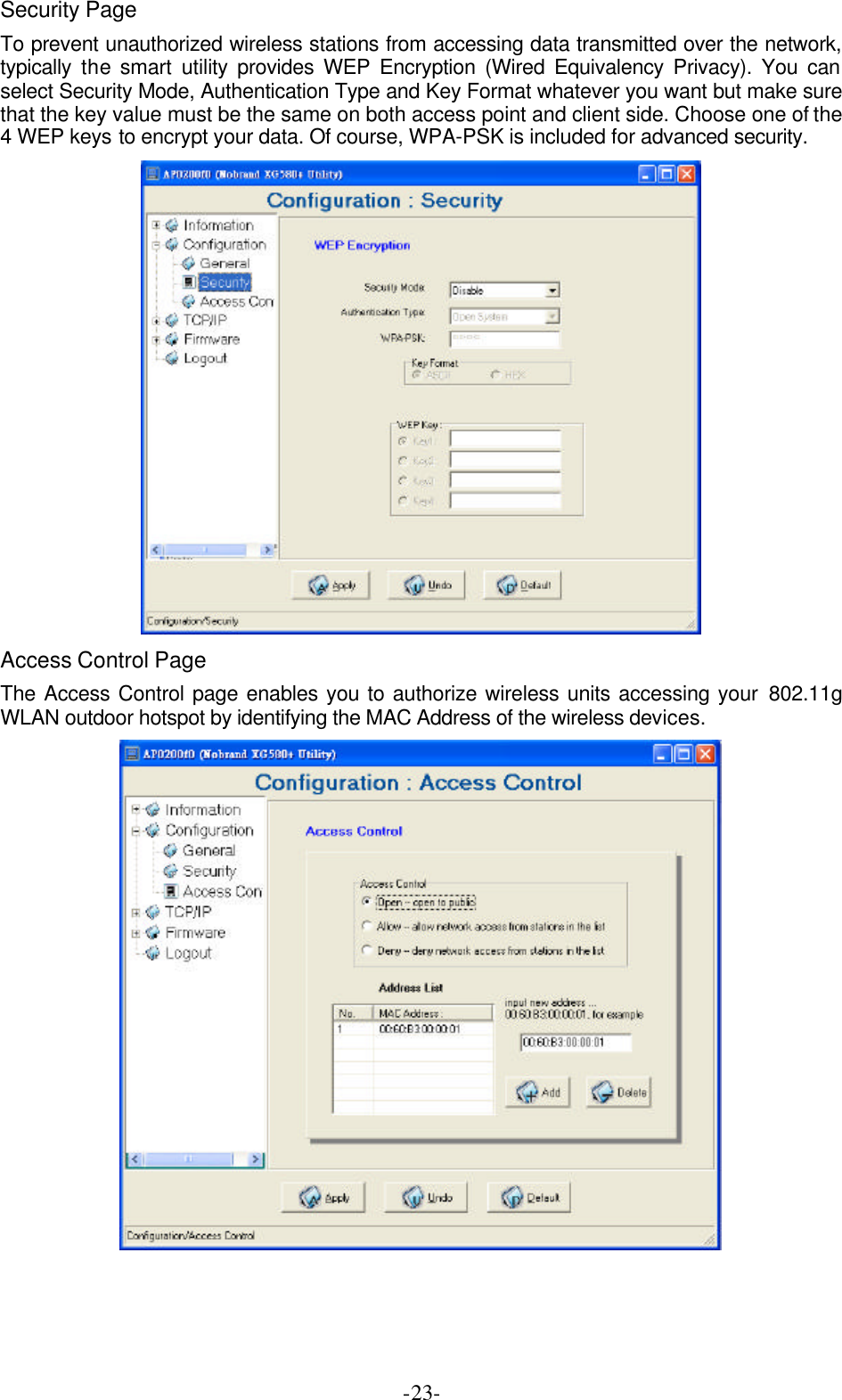
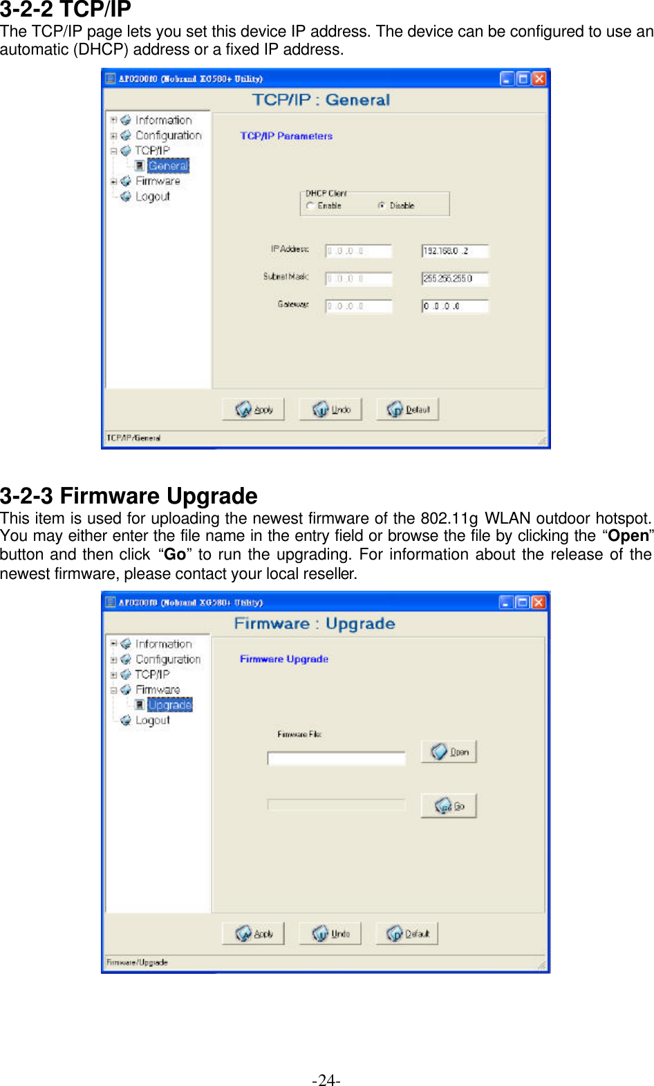
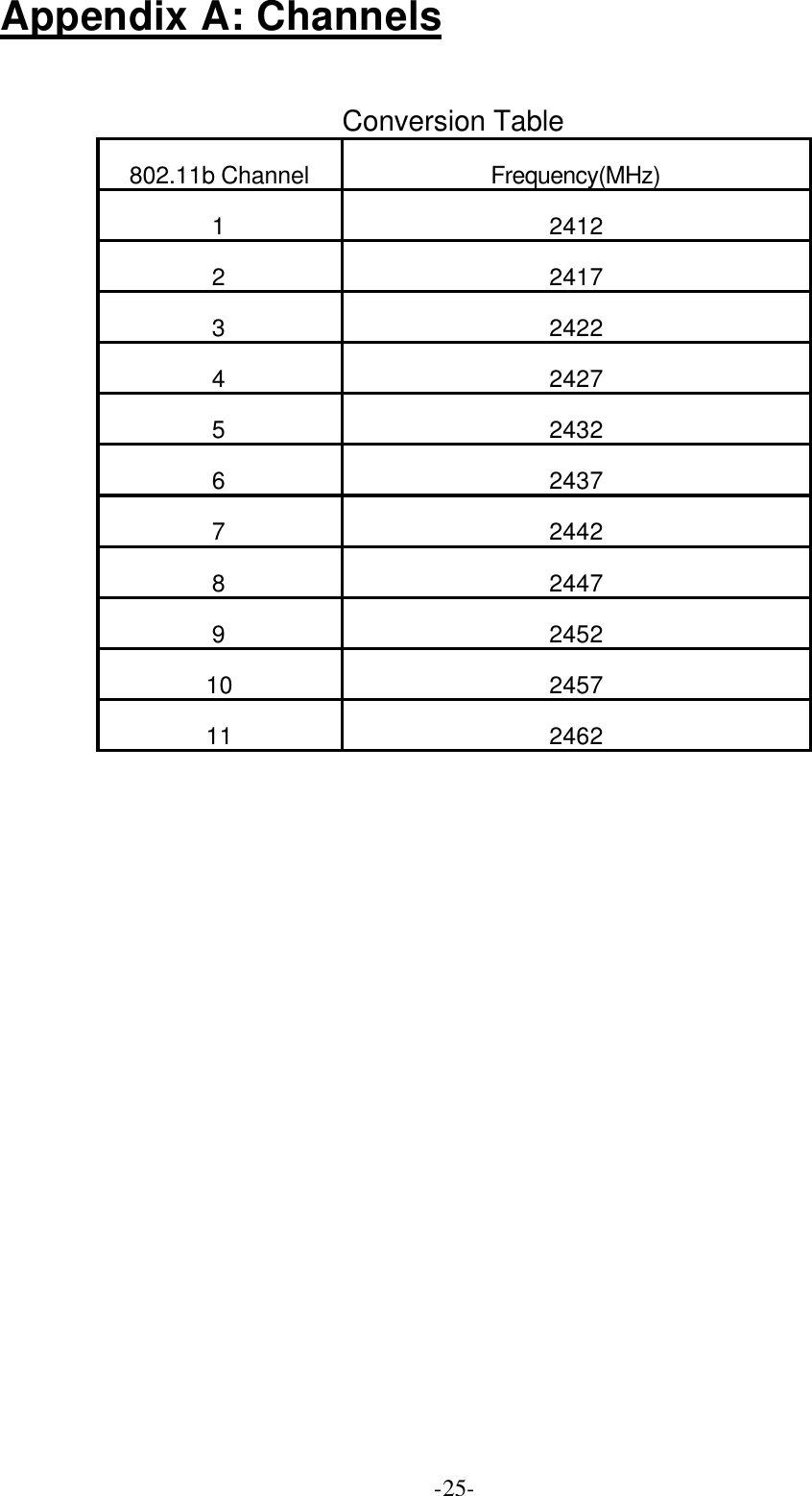
K Best Technology BL5201-001 802.11g Outdoor HotSpot User Manual 11g 5201 Manual V1 0 1

K-Best Technology Inc. 802.11g Outdoor HotSpot 11g 5201 Manual V1 0 1

User Manual

 Copyright Copyright © 2004 all rights reserved. No part of this publication may be reproduced, adapted, stored in a retrieval system, translated into any language, or transmitted in any form or by any means without the written permission of the supplier.   About This Manual The purpose of this manual is for the setup of the 54Mbps Wireless LAN ODU.  This manual,  first  version  1.0.1 in 2004, includes procedures assisting you in avoiding unforeseen problems.    Technical Support If you have difficulty resolving the problem while installing or using the Wireless LAN ODU, please contact the supplier for support.
FCC Notice  FCC Certified Declaration: This device complies with part 15 of the FCC rules. Operation is subject to the following two conditions: (1) This device may not cause harmful interference and (2) this device must accept any interference received, including interference that may cause undesired operation.  Reminder: To comply with FCC part 15 rules, the ODU must only be used as a system as FCC certified. The system must also be professionally installed to ensure compliance with the Part 15 certification. It is the responsibility of the operator and professional installer to ensure that only certified systems are deployed in where FCC rules apply. Further, according to FCC Part 15 regulations, Section 15.247(b)(3)(iii), the installer must ensure that the high-gain directional antenna used in this system is used exclusively for fixed, point-to-point operations and that multiple co-located intentional radiators transmitting the same information are not used. For further information, please see Appendix B.  Notice :  The changes or modifications not expressly approved by the party responsible for compliance could void the user’s authority to operate the equipment.  IMPORTANT NOTE:  To comply with the FCC RF exposure compliance requirements, the antenna(s) used for this transmitter must be installed to provide a separation distance of at least 20 cm from all persons and must not be co-located or operating in conjunction with any other antenna or transmitter. No change to the antenna or the device is permitted. Any change to the antenna or the device could result in the device exceeding the RF exposure requirements and void user's authority to operate the device.
Table of Contents  FCC Notice..............................................................................................3 Chapter 1  Introduction .......................................................................5 1-1 Features and Benefits............................................................................. 5 1-2 Applications.......................................................................................... 6 1-3 System Configurations........................................................................... 7 Chapter 2  Hardware Installation.....................................................8 2-1 Product Kit............................................................................................ 8 2-2 System Requirements ............................................................................. 8 2-3 Mechanical Description ......................................................................... 9 2-4 Hardware Installation.......................................................................... 10 Chapter 3  Configuring the ODU....................................................11 3-1 Using the Web Management................................................................. 11 3-1-1 How to access the web-browser configuration utility? ................................11 3-1-2 Information.........................................................................................................11 3-1-3 Configuration .................................................................................................... 12 3-1-4 TCP/IP ............................................................................................................... 18 3-1-5 Statistics ............................................................................................................ 19 3-1-6 Firmware Upgrade........................................................................................... 20 3-2 Using the WLAN outdoor hotspot Utility............................................... 21 3-2-1 Configuration .................................................................................................... 22 3-2-2 TCP/IP ............................................................................................................... 24 3-2-3 Firmware Upgrade........................................................................................... 24 Appendix A: Channels ........................................................................25 Appendix B: FCC Certified Systems..............................................26 Appendix C: Troubleshooting..........................................................27
 -5-Chapter 1  Introduction The 802.11g WLAN outdoor hotspot – 54Mbps Wireless Outdoor Unit, are specially designed for Point-to-Point and Point-to-Multipoint applications, offering long distance connections between buildings at a speed of up to 54Mbps.  Fully compliant with IEEE802.11b/g standard, the Outdoor Unit (ODU) provides powerful features such as the Windows-based configuration utility, MAC address filtering, WEP security, WDS application and more. 1-1 Features and Benefits n Creates a Point-to-Point connection linking two LANs, using 2 Indoor Units or Indoor and Outdoor total solutions. n Integrated 90 degree sector antenna provides the easy installation and cost effective hotspot and PTMP under 5 KM solution. n The ODU act as bridge and access point at the same time with the WDS function. n With a data rate up to 54Mbps, the system is faster than an E1/T1 data link. n Features 54Mbps data rate by incorporating Direct Sequence Spread Spectrum technology. n Fully IEEE 802.11b/g compatible. Allow inter-operation among multiple vendors. n Technique operating in the unlicensed 2.4GHz ISM band. n Seamless roaming within the 802.11 & 802.11b/g wireless LAN infrastructure. n Provides the highest available level of WEP /WAP-PSK as well as MAC Address Control to increase security. n MAC address Access Control. n Provides Window-based configuration utility. n IP67 rated weatherproof housing
 -6-1-2 Applications The 802.11g WLAN outdoor hotspot offers a fast, reliable, cost-effective solution for wireless client access to the network in applications like these: 1. Remote Access to Corporate Network Information E-mail, file transfer and terminal emulation. 2. Difficult-to-Wire Environments Historical or old buildings, asbestos installations, and open area where wiring is difficult to deploy. 3. Frequently Changing Environments Retailers, manufacturers and those who frequently rearrange the workplace and change location. 4. Temporary LANs for Special Projects or Peak Time C1- Trade shows, exhibitions and construction sites where a temporary network will be practical.   C2- Retailers, airline and shipping companies need additional workstations during peak period. C3- Auditors requiring workgroups at customer sites. 5. Access to Database for Mobile Workers Doctors, nurses,  retailers, accessing their database while being mobile in the hospital, retail store or office campus. 6.    High Security Connection The secure wireless network can be installed quickly and provide flexibility. (Please refer to page 16 for more information on encryption configuration.)
 -7-1-3 System Configurations The 802.11g WLAN outdoor hotspot can be configured in a variety of network system configurations such as AP mode, Station mode or AP with repeating mode.  l AP Mode:   The system can be configured to work as a wireless network access point. Note that the 802.11g WLAN outdoor hotspot acts only as a layer 2 bridge and does not act as a DHCP server. In other words, it does not supply dynamic IP addresses and instead relies on the network to supply them. The implementation can be shown as below:     l Station mode When configuring as a station mode, the device is now acting as a wireless client. The 802.11g WLAN outdoor hotspot will associate to an AP within its range in infrastructure mode, or join with another outdoor bridge device in Client mode in an ad-hoc network  l Install an AP with repeating   In this mode, you can extend the range of a wireless network. Wireless clients can associate with the repeater to communicate with each client on your network. Note that all the Access Points’ IP address must be set in the same network and make sure that Channel is set the same for all of your AP with repeating(s)
 -8-Chapter 2  Hardware Installation This chapter describes initial setup of the Wireless LAN ODU subsystem. 2-1 Product Kit Before installation, make sure that you the following items: u 802.11g WALN Outdoor Bridge……….…..…………….……..x 1 u Power over Ethernet………………………………….……….…x 1 u Power Adapter……………………………….…….…………..…x 1 u Power Cord……………………………………………………..…x 1 u Mounting kit..……………………………….………………….....x 1 u Product CD……………………………………………………..…x 1 u Quick Installation Guide……………………………….……….x 1  NOTE: If any of the above items are missing or damaged, please contact your local dealer for support. 2-2 System Requirements Installation of the 54Mbps Wireless LAN ODU requires:  1. A DC adapter which supplies the power for the PoE (Power over Ethernet). 2. A cross over 10/100 Base-T (UTP) Ethernet cable drop. 3. Operating system support: Windows 98/Me/NT4.0(SP4 or above)/2000/XP
 -9-2-3 Mechanical Description ODU:       LED Indicator  Product type LED Indicator 100mW Power ※ Tx / Rx led indicator only act in 0.5W / 1W products. Waterproof RJ-45 connector Connect to the POE with SFTP cable.  SFTP Cable This cable is attached to the ODU. The default SFTP cable length is 25 meter.     LED Indicator RJ-45(To POE) Power Tx Rx
 -10-2-4 Hardware Installation Take the following steps to set up your ODU. n Connect the Ethernet Cable The 54Mbps Wireless LAN ODU supports 10/100M Ethernet connection.  Connect the SFTP cable from the ODU to the RJ-45 connector of PoE (marked “To ODU”) for ODU connection. Then connect the other end of the POE with straight RJ-45 cable to a hub or a switch. Please note that, use the cross-over cable when you desire to connect the PoE of ODU to a PC. n Connect the Power Cable Connect DC 15V adapter to the PoE, and plug the other end of the adapter into an electrical outlet.   NOTE: Only use the power adapter supplied with the PoE of ODU. Otherwise, the product may be damaged.
 -11-Chapter 3   Configuring the ODU  The 802.11g WALN outdoor bridge is shipped with default parameters, which will be suitable for the typical infrastructure/ad-hoc wireless LAN. Just simply install the 802.11g WLAN outdoor hotspot, power it on, and it is now ready to work. Nevertheless, you can still switch the configuration settings depending on how you would like to manage your wireless network. You are allowed to configure the 802.11g WLAN outdoor hotspot with a web browser (Web Management), or the smart configuration utility, known as an Access Point Manager. 3-1 Using the Web Management The built-in Web Management provides you with a user-friendly graphical user interface (web pages) to manage your 802.11g WLAN outdoor hotspot.  3-1-1 How to access the web-browser configuration utility?  1. Connect your computer to the wireless adapter either through wireless or wired connection. Please set a fixed IP address (refer to Chapter 6), within the range of 192.168.0.X (X can’t be 2), to your computer.   2. Activate your browser, then type this 802.11g WLAN outdoor hotspot’s address (e.g. http://192.168.0.2), in the Location (for IE) or Address field and press Enter.    3. Key in the system password (the default setting is “default”) and click on the “Login” button. You will see the main page.  The main window provides 5 items for you to monitor and configure the Wireless 802.11g WLAN outdoor hotspot: Information, Configuration, TCP/IP, Statistics and Firmware Upgrade.  3-1-2 Information This item shows the current information on the 802.11g WLAN outdoor hotspot such as MAC Address, Firmware Version, Web UI Version as well as Boot Version.
 -12-  3-1-3 Configuration     General Page Access Point Name: In this field, you may enter any name. This will enable you to manage your 802.11g WLAN outdoor hotspot more easily if you have multiple 802.11g WLAN outdoor hotspots on the network. Besides, Access Point Name can be used to prevent you from forgetting an IP Address and fail to access the website. Try to type the nickname you like to identify the website, then press the button of “Apply” to reboot. Whenever you want to get back to the website again, just type the name you login.
 -13-Wireless Mode: The default wireless operating mode of the 802.11g WLAN outdoor hotspot is Access Point (AP) mode. To switch to Station or AP with repeating mode, select the desired mode from the down-arrow menu. Click Apply. The board will reboot into the desired mode. l AP Mode: The system can be configured to work as a wireless network access point. Note that the 802.11g WLAN outdoor hotspot acts only as a layer 2 bridge and does not act as a DHCP server. In other words, it does not supply dynamic IP addresses and instead relies on the network to supply them. The implementation can be shown as below:  l Station Mode: When configuring as a station mode, the device is now acting as a wireless client. The 802.11g WLAN outdoor hotspot will associate to an AP within its range in infrastructure mode, or join with another device in Client mode in an ad-hoc network.   l AP with repeating: In this mode, you can extend the range of a wireless network. Wireless clients can associate with the repeater to communicate with each client on your network. Note that all the Access Points’ IP address must be set in the same network and make sure that Channel are set the same for all of your AP with repeating(s).  Enable MacClone:  This feature has provided the ability to automatically clone (copy) the MAC address of the computer or Ethernet devices to the 802.11g WLAN outdoor hotspot. In certain circumstances you may have to use a specific non-TCP/IP device. In order to allow the non-TCP/IP devices to connect to the particular service that requires TCP/IP protocol, you need to clone the MAC address of the device that was original connected to the 802.11g WLAN outdoor hotspot. Cloning your MAC address will not cause any problems with your wireless network. Simply clicking the check box next to “Enable MacClone” and press “Apply”, your MAC address will be cloned to the 802.11g WLAN outdoor hotspot. Network Type: There are 2 network types for the wireless station adapter to operate. If you need to access company network or Internet via Access Point, select “Infrastructure”. To set up a group of wireless stations for files and printer sharing, select “Ad-Hoc” (without Access Point). For Ad-Hoc operation, the same ESSID is required to set for the wireless stations. ESSID: The ESSID is a unique ID used by Access Points and Stations to identify a wireless LAN. Wireless clients associating to any Access Point must have the same ESSID. The default ESSID is ANY.  The ESSID can have up to 32 characters.
 -14-Channel: Select a clear and available channel as an operational channel for your wireless station adapter when it performs as Ad-Hoc mode or AP with repeating mode. Mode: There are three different wireless modes to operate, “B Only Mode”, “G Only Mode”, and “B/G Mixed Mode”. In B/G Mixed Mode, the wireless station adapter is compatible with a mix of both 802.11g and 802.11b clients. You will see that the factory-set default “B/G Mixed Mod” will prove the most efficient. B Only Mode is compatible with 802.11b clients only. This mode can be used only if you do not allow any 802.11g clients to join a network. G Only Mode is compatible with 802.11g clients only. This mode can be used only if you do not allow any 802.11b clients to access to the network. To switch the mode, select the desired mode form the pull-down menu next to “Mode”.   Rate: The wireless station adapter provides various data rate options for you to choose. Data rates options include Auto, 1, 2, 5.5, 11, 6, 9, 12, 18, 24, 36, 48 and 54. The default setting is Auto. Country/Region: Allows you to select country domain in case there is any chances that you would use wireless network in other countries. There are a total of 11 countries for you to select. They are Africa, Asia, Australia, Canada, Europe, France, Israel, Japan, Mexico, South America, and USA. Note that if your AP and station adapter are in different standards, please use the “Country/Region” item to switch the standards of the station adapter (For example, when set to client mode, if your Access Point is America standard but your station adapter is Japanese standard, you can pull down the “Country/Region” option to switch your station adapter from Japanese standard to American standard.). As long as you change the country domain, the channel will switch to correspond with the country you changed.  Password: You may change the default password by entering the new password. Click “Apply” if you have made any changes.  Security Page  Security Mode: This 802.11g WLAN outdoor hotspot allows you to create up to 4 data encryption keys to secure your data from being eavesdropping by unauthorized wireless users. To enable the encryption, all devices on the network must share the same WEP key. Disable:  Allows the wireless station AP to communicate with the Access Point without any data encryption. WEP40:  Requires  the  wireless station adapter  to use data encryption with 40-bit algorithm when communicating with the Access Point.
 -15-WEP128: Allows the wireless station adapter to communicate with the Access Point with data 128-bit encryption algorithm. WPA-PSK:  Allows the  wireless station adapter to communicate with the Access Point with a more secure data protection than the WEP. Here you can select the WPA with PSK mode to improve the data security and privacy during wireless transmission. The present WPA supplied with this 802.11g WLAN outdoor hotspot is used in a pre-shared key mode, which does not require an authentication (Radius) server. Moreover, the 802.11g WLAN outdoor hotspot provides three types of authentication services: Auto, Open System and Shared Key. The default authentication type is Auto. Open System requires no authentication since it allows any device to join a network without performing any security check. If you require higher security for wireless access, you may select Shared Key. Note that when Shared Key is selected, a WEP key is required and must be the same between the Access Point and client.   For 40bit encryption you may choose: ASCII: Enter 5 characters (case sensitive) ranging from “a-z”, “A-Z” and “0-9” (e.g. MyKey).   Hex: Alternatively, you may enter 10 hexadecimal digits in the range of “A-F”, “a-f” and “0-9” (e.g. 11AA22BB33). For 128bit encryption you may choose: ASCII:  Enter 13 characters (case sensitive) ranging from “a-z”,  “A-Z” and  “0-9” (e.g. MyKey12345678). Hex: Alternatively, you may enter 26 hexadecimal digits in the range of “A-F”, “a-f” and “0-9” (e.g. 00112233445566778899AABBCC). After entering the WEP keys in the key field, select one key as active key.
 -16-Alternatively, you may create encryption keys automatically by using Passphrase. From the Passphrase field, type a character string and click “Generate”. As you type, the 802.11g WLAN outdoor hotspot will use an algorithm to generate 4 keys automatically. Select one key from the 4 WEP keys. For WPA-PSK mode you may choose: In the WPA-PSK field, you may input 8-63 characters ranging from “a-z”, “A-Z” and “0-9”. If you require that access to the Internet or other wireless network services are allowed only when the pre-shared key of the 802.11g WLAN outdoor hotspot matches that of the device you want to communicate.  Click the “Apply” button on the Configuration tab to make the setting take effect.  Access Control Page  When configuring the 802.11g WLAN outdoor hotspot with AP mode operation, the Access Control is a powerful security feature that allows you to specify which wireless stations are allowed or denied in the list including: Open: Allows any wireless station to access the network.   Allow: Any wireless station in this list attempting to access the network is allowed. Deny: Any wireless station in this list will be denied access. To add the Mac address of each wireless station on your network by entering the Mac address of the client you desire to add into the list. Click “Add”, and then “Apply” to save the settings. To delete a Mac address from the list, select the Mac address you want to delete by clicking “Del” and then “Apply” to save the settings.
 -17-
 -18-Parameter log Page The Parameter log item allows you to save settings to the local hard drive by clicking “Save”. When you click the “Browse” button, you can select the saved setting files. To click “Load”, the saved settings will be loaded back.  3-1-4 TCP/IP You may assign a proper IP address to your 802.11g WLAN outdoor hotspot manually. If you would like the 802.11g WLAN outdoor hotspot to obtain the IP address from the DHCP server on your network automatically, enable the DHCP client function. Click the “Apply” button to make it effect. The default IP Address is 192.168.0.2.
 -19-3-1-5 Statistics General Page This item will allow you to monitor the connection status when set to AP mode such as the Mac Address, Link Status, Rate Type as well as RX/TX from Ethernet packets.   When set to Client mode, you may also open the General page to view the available Access Points around your environment. The status includes Link Status, ESSID, BSSID, Channel and Signal as well as RX/TX from Ethernet packets.   AP Browser Page This AP Browser shows only when configuring your  802.11g  WLAN outdoor hotspot as Station mode. By clicking the “Refresh” button, the AP Browser will reload and display available Access Points around the working  environment. Besides showing the BSSID of each Access Point, it also displays ESSID, Channel, Support Rate and Capability. To connect one of displayed Access Points, just select the Access Point you desire and then click the “Connect” button to make the connection.
 -20- 3-1-6 Firmware Upgrade Here, you can upload the latest firmware of the 802.11g WLAN outdoor hotspot. You may either enter the file name in the entry field or browse the file by clicking the “Browse” button.  Then click the “Apply” button to begin to upgrade the new firmware.
 -21-3-2 Using the WLAN outdoor hotspot Utility Install the 802.11g WALN outdoor bridge on your Windows 95/98/NT/ME/2000 desktop computer, the Windows-based utility “Nobrand smart Utility” provides an easy-setup interface. The smart Utility enables you to configure your 802.11g WLAN outdoor hotspot on the network more easily than ever before. The following gives instructions guiding you through the installations of the Access Point Utility. 1. Insert the Product CD-ROM or floppy disk that came with your product kit into the corresponding drive on your computer. 2. Go to the Nobrand Smart Utility folder and click Setup.exe. The installation screen will show up. Click Next to continue. 3. Follow the on-screen instructions to install the Nobrand Smart Utility. 4. Upon completion, go to Program Files and execute the Wireless Utility. It will begin to browse the 802.11g WLAN outdoor hotspot on the network.   5. Double-click the icon to access the property dialog box. Enter the password in the entry field. The default password is “default”.
 -22- 6. After entering the correct password, a main window appears. You will see the basic information of the 802.11g  WLAN outdoor hotspot, such as MAC Address, Firmware, Web UI, Boot and Utility version.    MAC Address: It is a hardware identification number that distinguishes the unit from others. You will see this number on the sticker of the 802.11g WLAN outdoor hotspot. Firmware Version: Displays the firmware version that is equipped with your hardware.  3-2-1 Configuration   General Page You may make the settings on your 802.11g WLAN outdoor hotspot such as Access Point Name, Wireless Mode, Network Type, ESSID, TX Rate, Country/Region, Channel and Password.
 -23-Security Page To prevent unauthorized wireless stations from accessing data transmitted over the network, typically  the smart utility provides WEP Encryption (Wired Equivalency Privacy). You can select Security Mode, Authentication Type and Key Format whatever you want but make sure that the key value must be the same on both access point and client side. Choose one of the 4 WEP keys to encrypt your data. Of course, WPA-PSK is included for advanced security.  Access Control Page The Access Control page enables you to authorize wireless units accessing your 802.11g WLAN outdoor hotspot by identifying the MAC Address of the wireless devices.
 -24-3-2-2 TCP/IP The TCP/IP page lets you set this device IP address. The device can be configured to use an automatic (DHCP) address or a fixed IP address.   3-2-3 Firmware Upgrade This item is used for uploading the newest firmware of the 802.11g WLAN outdoor hotspot. You may either enter the file name in the entry field or browse the file by clicking the “Open” button and then click “Go” to run the upgrading. For information about the release of the newest firmware, please contact your local reseller.
 -25-Appendix A: Channels  Conversion Table 802.11b Channel Frequency(MHz) 1 2412 2 2417 3 2422 4 2427 5 2432 6 2437 7 2442 8 2447 9 2452 10 2457 11 2462
 -26-Appendix B: FCC Certified Systems  FCC ID#: QZGBL5201-001 FCC Certified Systems consist of:     Ø BL5201 WLAN ODU,PoE,Power Adapter,Power Cord,SFTP Cable Ø UTP RJ-45 Cable  The WLAN ODU has passed the FCC regulations: FCC part 15, subpart C(2002)
 -27-Appendix C: Troubleshooting If there is no signal output, please check the following item: 1. Check whether the LED indicator on the PoE and ODU is on. If not, it means there is problem with the power component.   (1) Check if the power cord is correctly connected with the power adapter and the power outlet. (2) Check if there is electricity on power outlet.   2. Check if the connection between antenna and WLAN ODU is correct, or whether the connector is loose or not. 3. Check if the connection between WLAN ODU and PoE is correct, or whether the connector is loose or not. 4. Verify if the transmit power which calculated before is correct. 5. If none of the above measures could solve troubleshooting, please contact the supplier for further support.

Navigation menu