KAPSCH TRAFFICCOM CANADA 801154 Compact RF Module, model 801154 User Manual 287265
KAPSCH TRAFFICCOM CANADA INC. Compact RF Module, model 801154 287265
Contents
- 1. Installation instructions
- 2. Specifications
- 3. Revised user manual
- 4. Revised user manual containing RF exposure statement
- 5. revised installation instructed with corrected RF exposure statement
Revised user manual containing RF exposure statement
CR2000 Reader Installation Instructions Document A316000-775
2001 MARK IV INDUSTRIES LTD. Revision B, Issue printed on 12/4/2002 10:27 AM, filename: E:\Ready_To_Convert\Doc\287265.DOC
CONFIDENTIAL: This document is the confidential property of Mark IV Industries Ltd. and may not be released or copied without written permission.
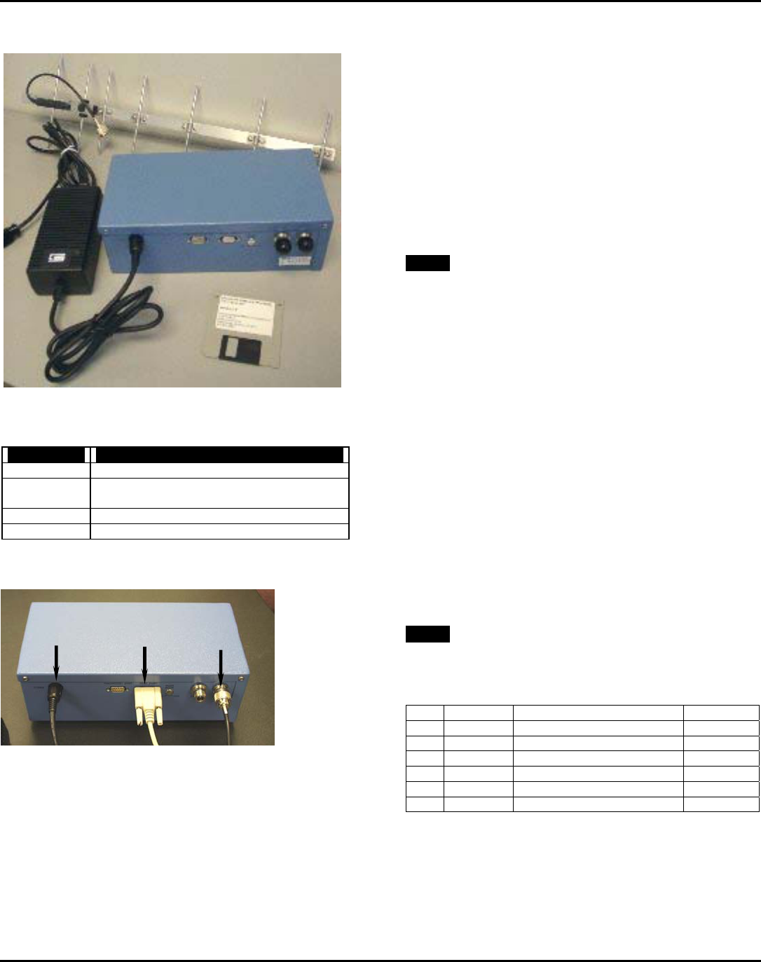
CR2000 - Reader Kit
CR2000 - Reader Kit Packing List
Part Number Description
801075-001 CR2000 Compact Reader
318993-009 DC Power Pack, 110Vac input, output 5V/3A,
15V/1.5A, -15V/0.3A, Skynet #SNP-PA54
318145-177 CR2000 PC Software on Diskette
801076-001 Antenna Assembly
CR2000 Reader - Connections
CR2000 - Installation Tools
Your tool kit should include (but is not limited to)…
♦ N-type connector crimp tool
♦ screwdrivers: flat blade, Philips blade
♦ SAE Socket set
♦ utility knife, wire cutter, wire stripper
CR2000- Installation Items
The kit of reader components described at left does not
include the following required items…
1 PC cable, RS232 (DTE-DCE), 12 feet (see Fig 1)
A/R antenna mount hardware: bracket(s), clamp(s), mast, etc.
100 feet (or less A/R) of RG213U cable
2.5 feet of RG58U cable
1 N-male connector for RG213U cable
1 N-female connector for RG213U cable
1 N-male connector for RG58U cable
1 N-female connector for RG58U cable
1 each of fixed attenuators: 1, 2, 3, 4, 5, 6, and 7 dB
A/R heat shrink tubing, electrical tape, cable ties and clamps
NOTE: During system installation, the contractor determines
the fixed RF attenuation level required.
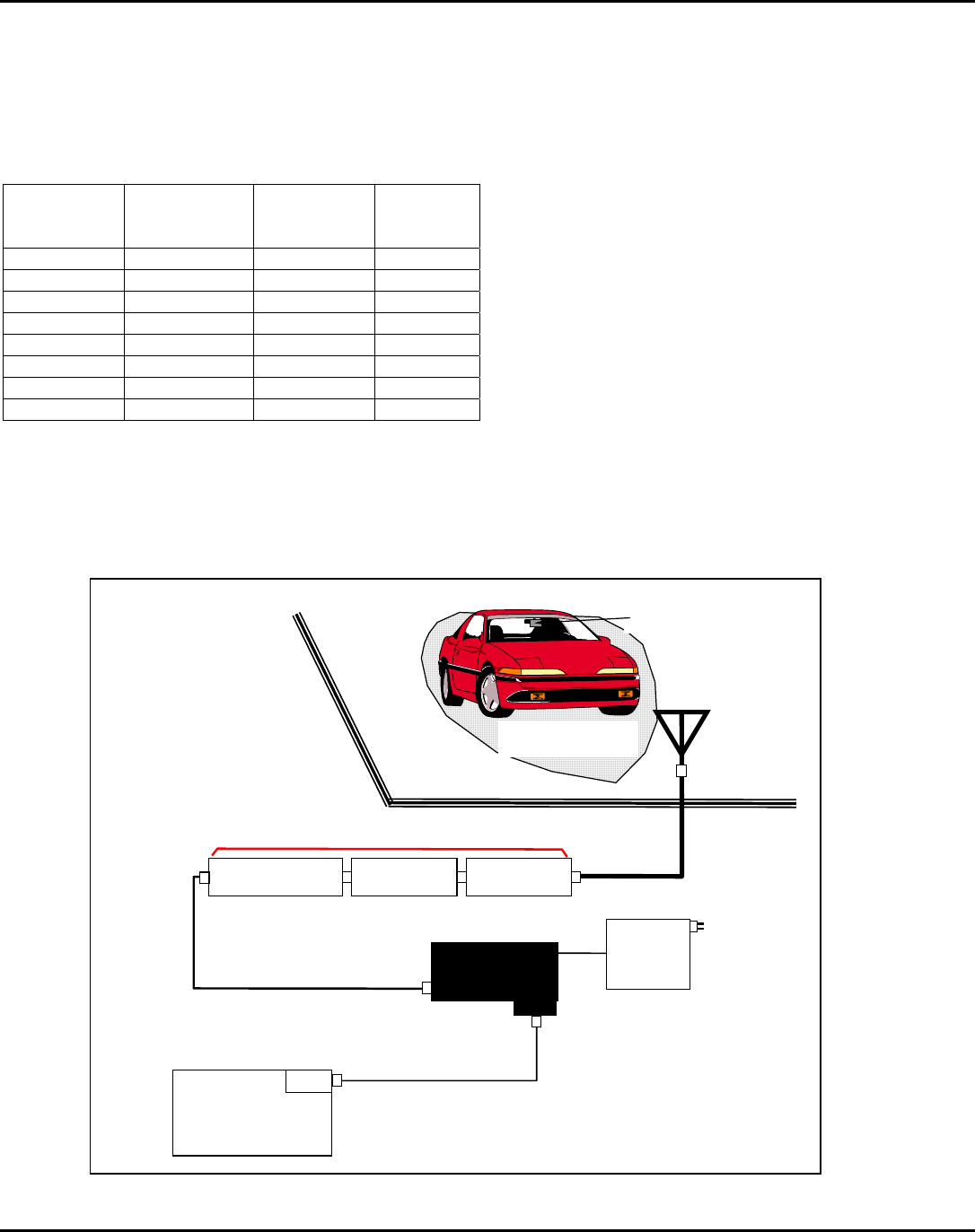
CR2000- Installation Overview
♦ The antenna is installed within the distance/angular limits
of the "pick-up point" as indicated in Table 1 on the back
page
♦ The reader, power pack, antenna adapter cable and "total
RF attenuation" components are installed at a location
inside the building (see Figure 1 on the back page) that is
(all of)…
within 6 feet of a 110Vac power main drop
within 12 feet (4 meters) of the host computer
within 100 feet of the antenna mounting location
outside the building
♦ All system connections are completed as indicated in the
CR2000 - Installation Steps listed on the back page.
♦ The CR2000 PC application software is transferred from
the diskette to the host computer and is running.
♦ The total RF attenuation value is determined by varying
the configuration of the available fixed attenuators.
NOTE: Where necessary, Mark IV Industries Ltd. I.V.H.S.
personnel may be required to "fine tune" the system RF
attenuation parameters.
Document Revision Record
Rev Date ECN Approved
A 18-Jan-01 Preliminary
power
cable
antenna
adapter
cable
PC
cable
CR2000 reader
antenna
software diskette
power
pack
CR2000 Reader Installation Instructions Document A316000-775
2001 MARK IV INDUSTRIES LTD. Revision B, Issue printed on 12/4/2002 10:27 AM, filename: E:\Ready_To_Convert\Doc\287265.DOC
CONFIDENTIAL: This document is the confidential property of Mark IV Industries Ltd. and may not be released or copied without written permission.
CR2000 - Antenna mounting
The antenna will be mounted over-head at a height of Ha ft
with horizontal polarization where Ha is measured from the
highest part of the antenna. Determine the distance Do (in ft)
between the "pick-up point" and the antenna mast, and use it
to determine the antenna tilt down angle α° in the in-lane
direction (H Plane), using the following table.
Antenna
Height (Ha)
[ft]
Pick-up Point
(Do) *
[ft]
Antenna Tilt
Angle (α)
[Deg]
Beam
Center **
[ft]
12 5 to 7 15 3
7 to 9 18 4
12.5 5 to 7 15 3
7 to 9 18 4
13 6 to 8 15 3.5
8 to 10 18 4.5
13.5 7 to 9 15 4
9 to 10 18 4.5
* Distance referred to the antenna mast.
** Based on semi-empirical data.
Note: This device shall cause no harm at a distance greater
than 1 meter away from the antenna. The antenna has gain of 6
db.
CR2000 - Installation Steps
Connect the antenna with the reader via RF feedline and RF
attenuator(s) and antenna adapter cable.
1) Disconnect the power main input to the power supply.
2) Connect the Power supply output to the CR2000 reader.
3) Connect the PC port COM1 to the reader host port using
the provided straight through RS-232 cable.
4) Connect the RF cable adapter (RG58 short cable) to the
reader RF port (Type N connector).
5) Connect the RF feedline to the RF cable adapter via the
fixed attenuator(s) referenced in step 9. Install a Type-N
Male connector at the end of the feedline.
6) Route the RF feedline through the wall. At the feedline
antenna end, slip 6" of heatshrink tubing on the cable.
Install a Type-N female connector at the end of the
feedline. Make the connection with the antenna.
7) Reconnect the power main input to the power supply.
8) Execute the CR2000 PC application software as
referenced in document A316000-743.
9) Determine the "total RF attenuation" value by varying the
configuration of the available fixed attenuator value(s).
10) After the system has been fully tested OK then heat shrink
the tubing (in step 6) over the antenna connector to make
it water tight.
Figure 1 - Installation Diagram
attenuator attenuator
N male
N male
N female
N male
RF cable
RG213U
< 100 ft
N female/female
attenuator ***
N male
N male/female
antenna
RF cable
RG58U
< 2.5 ft
CR2000
Reader
N female
N male/female
DC
power
pack
110 Vac
mains
supply
Host PC
running
CR2000-PC
software
DB9 female Host port (P2)
DB9 female*
DCE
DB9 male
DB9 male*
RS232 cable
#22AWG, 3 conductor
> 6 ft < 40 ft (12 ft default or specify)
Optional: RS485 cable
#22AWG, 5 conductor
> 40 ft < 200 ft (always specify)
DTE
vehicle with a
transponder
"RF capture zone"
when RF is turned on
outside the building
inside the building
***total RF attenuation" value
is determined at the end of
the installation process
antenna adapter cable
antenna feedline cable
"total RF attenuation" value
*Please verify the serial port
connector type on your host
PC, is it DB9 or DB25?
PC cable