KAPSCH TRAFFICCOM CANADA 801800A Janus Exterior Transponder User Manual for trucks and buses

KAPSCH TRAFFICCOM CANADA INC. Janus Exterior Transponder for trucks and buses

Contents

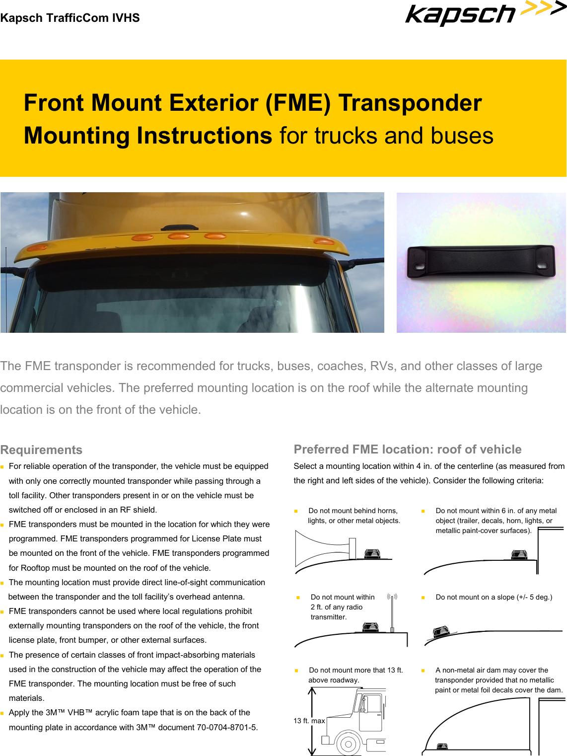
user manual for trucks and buses

Kapsch TrafficCom IVHS Front Mount Exterior (FME) Transponder Mounting Instructions for trucks and buses The FME transponder is recommended for trucks, buses, coaches, RVs, and other classes of large commercial vehicles. The preferred mounting location is on the roof while the alternate mounting location is on the front of the vehicle.  Preferred FME location: roof of vehicle Select a mounting location within 4 in. of the centerline (as measured from the right and left sides of the vehicle). Consider the following criteria: Requirements  For reliable operation of the transponder, the vehicle must be equipped with only one correctly mounted transponder while passing through a toll facility. Other transponders present in or on the vehicle must be switched off or enclosed in an RF shield.  FME transponders must be mounted in the location for which they were  programmed. FME transponders programmed for License Plate must be mounted on the front of the vehicle. FME transponders programmed for Rooftop must be mounted on the roof of the vehicle.  The mounting location must provide direct line-of-sight communication between the transponder and the toll facility’s overhead antenna.  FME transponders cannot be used where local regulations prohibit externally mounting transponders on the roof of the vehicle, the front  license plate, front bumper, or other external surfaces.  The presence of certain classes of front impact-absorbing materials used in the construction of the vehicle may affect the operation of the FME transponder. The mounting location must be free of such  materials.  Apply the 3M™ VHB™ acrylic foam tape that is on the back of the mounting plate in accordance with 3M™ document 70-0704-8701-5.   Do not mount behind horns, lights, or other metal objects.   Do not mount within 6 in. of any metal object (trailer, decals, horn, lights, or metallic paint-cover surfaces).   Do not mount within 2 ft. of any radio transmitter.   Do not mount on a slope (+/- 5 deg.)   Do not mount more that 13 ft. above roadway. 13 ft. max   A non-metal air dam may cover the transponder provided that no metallic paint or metal foil decals cover the dam.
If securing the transponder WITH the mounting plate: 1. The back of the mounting plate is covered with 3M™ VHB™ acrylic foam tape. Prepare the mounting location in accordance with 3M™ document 70-0704-8701-5. NOTE: Ensure the mounting plate is installed on the vehicle so that when the transponder is installed on the mounting plate, the orientation arrows on the transponder point in the direction of forward travel. 2.  Remove the protective backing from the adhesive on the back of the mounting plate and firmly press the mounting plate against the mounting surface with either a roller or platen pressure, maintaining pressure for 15 seconds to ensure a good bond. 3.  Using the supplied tamper-proof nuts, lock washers, and flat washers, secure the transponder to the mounting plate with the notches on the transponder and mounting plate aligned and with the orientation arrows on the  transponder pointing in the direction of forward travel. ©Kapsch TrafficCom IVHS. All rights reserved Subject to alteration without notice. Kapsch Group The Kapsch Group and its entities Kapsch TrafficCom, Kapsch CarrierCom and Kapsch BusinessCom are specialized in the future-oriented market segments of Intelligent Transportation Systems (ITS) and Information and Communication Technologies (ICT). Kapsch. Always one step ahead. 801850-002 rev C.  Kapsch TrafficCom IVHS | 6020 Ambler Drive | Mississauga, Ontario L4W 2P1 | CANADA | Phone +1 905 624 3020 | Fax +1 905 625 6197 54 S. Commerce Way, Suite 100 | Bethlehem, PA 18017 | USA | Phone +1 610 419 1479 | Fax +1 610 419 1489 E-Mail ktc.ca.info@kapsch.net | ktc.us.info@kapsch.net | www.kapsch.net If securing the transponder WITHOUT the mounting plate: NOTE: The transponder mounting holes must be used when securing the transponder to the roof of the vehicle using this method.  1.  Place the transponder in the selected mounting location. Using the transponder mounting holes as a guide, mark the locations on the roof through which the mounting bolts will pass. Remove the transponder. 2. Drill a mounting bolt hole at both locations marked in step 1. 3. Using two, ¼- in.-diameter stainless steel mounting bolts of sufficient length, two tamper-proof nuts, two lock washers, and two stainless steel flat washers, secure the transponder to the roof of the vehicle with the orientation arrows on the transponder pointing in the direction of forward travel. 4.  Apply sealant to the mounting bolts and mounting location as necessary. transponder tamper-proof  nut flat washer mounting bolt Alternate FME location: front of vehicle Select a mounting location either on the front license plate using the license plate mounting screws or on the front of the vehicle using the mounting plate. Consider the following criteria:  A:  a minimum of 24 in. clearance if bumper or large object extends 7+ in. (A1). B:  a minimum of 15 in. from the top of the transponder to the roadway for front bumper mounting. C:  the transponder must be mounted within 4 in. of the vehicle center. B A B C A  A1 If mounting the transponder on the front license plate: 1.  Remove the two upper license plate mounting screws securing the license plate to the front of the vehicle. 2.  Using the license plate mounting screws removed in step 1, secure the transponder, with orientation arrows pointing skyward, and the license plate to the front of the vehicle. If mounting the transponder elsewhere on the front of the vehicle: 1. The back of the mounting plate is covered with 3M™ VHB™ acrylic foam tape.  Prepare the mounting location in accordance with 3M™ document 70-0704-8701-5. NOTE: Ensure the mounting plate is installed on the vehicle so that when the transponder is installed on the mounting plate, the orientation arrows on the transponder point in the direction of forward travel. 2.  Remove the protective paper from the adhesive on the back of the mounting plate and firmly press the mounting plate against the mounting surface with either a roller or platen pressure, maintaining pressure for 15 seconds to ensure a good bond. 3.  Using the supplied tamper-proof nuts, lock washers, and flat washers, secure the transponder to the mounting plate with the notches on the transponder and mounting plate aligned and with the orientation arrows on the transponder pointing skyward.  tamper-proof nut lock washer flat washer transponder notch notch mounting plate mounting plate stud orientation arrow orientation arrow lock washer

Navigation menu