KAPSCH TRAFFICCOM CANADA 802041 Portable RSE User Manual Portable RSE
KAPSCH TRAFFICCOM CANADA INC. Portable RSE Portable RSE
User Manual

© Kapsch TrafficCom Canada Inc. 2012
These drawings and specifications contain confidential and proprietary information and are the property of Kapsch TrafficCom Canada Inc. and are issued in strict confidence
and will be kept confidential and used solely for the purpose intended and for no other purpose and shall not be transmitted, reproduced, copied, and/or used as the basis for
manufacture or sale of apparatus unless otherwise agreed to in writing by Kapsch TrafficCom Canada Inc.
Template: KTCIVHSQA180 Rev G July, 2012
Kapsch TrafficCom
Portable RSE
OPERATOR AND MAINTENANCE MANUAL
QMS EDITION - ISO9001:2008
DOCUMENT: UM 360453-700
REVISION: C
DATE: August 19, 2016
Editor: Scott Garlick
REVIEWERS: Stuart Lewis SYSTEMS ENGINEERING
Ed Rolo PROJECT MANAGEMENT
Tim Oaks TECHNICAL SERVICES
APPROVAL: Ed Rolo VP R&D
Japjeev Kohli VP SYSTEMS ENGINEERING

Portable RSE
DOC#: UM 360453-700 REVISION: C
© Kapsch TrafficCom Canada Inc. 2013
These drawings and specifications contain confidential and proprietary information and are the property of Kapsch TrafficCom Canada Inc. and are issued in strict confidence
and will be kept confidential and used solely for the purpose intended and for no other purpose and shall not be transmitted, reproduced, copied, and/or used as the basis for
manufacture or sale of apparatus unless otherwise agreed to in writing by Kapsch TrafficCom Canada Inc.
Template: KTCIVHSQA180 Rev G July, 2012
Kapsch TrafficCom
This page intentionally left blank.

Portable RSE
DOC#: UM 360453-700 REVISION: C
© Kapsch TrafficCom Canada Inc. 2013
These drawings and specifications contain confidential and proprietary information and are the property of Kapsch TrafficCom Canada Inc. and are issued in strict confidence
and will be kept confidential and used solely for the purpose intended and for no other purpose and shall not be transmitted, reproduced, copied, and/or used as the basis for
manufacture or sale of apparatus unless otherwise agreed to in writing by Kapsch TrafficCom Canada Inc.
Template: KTCIVHSQA180 Rev G July, 2012
Kapsch TrafficCom
PORTABLE RSE
OPERATOR AND MAINTENANCE MANUAL
QMS EDITION - ISO9001:2008
DOCUMENT: UM 360453-700
REVISION: C
DATE: August 19, 2016
Kapsch TrafficCom Canada Inc. Kapsch TrafficCom AG
6020 AMBLER DRIVE AM EUROPLATZ 2
MISSISSAUGA, ON L4W 2P1 1120 VIENNA, AUSTRIA
TEL: (905) 624-3020 TEL: +43 50 811 0
FAX: (905) 625-6197 FAX: +43 50 811 2109

Portable RSE
DOC#: UM 360453-700 REVISION: C Page 2 of 65
© Kapsch TrafficCom Canada Inc. 2013
These drawings and specifications contain confidential and proprietary information and are the property of Kapsch TrafficCom Canada Inc. and are issued in strict confidence
and will be kept confidential and used solely for the purpose intended and for no other purpose and shall not be transmitted, reproduced, copied, and/or used as the basis for
manufacture or sale of apparatus unless otherwise agreed to in writing by Kapsch TrafficCom Canada Inc.
FILE: P-RSE USER MANUAL - UM360453-700 REV_C.DOCX 08/19/2016 1:44
Kapsch TrafficCom
FCC License Notice:
This equipment emits RF signals. In order to operate this equipment the customer
must obtain a separate FCC Part 90 Site license for each location. In addition, the
FCC ID component identification “JQU802041” must appear on the unit.
NOTE: This device complies with Part 15 of the FCC Rules. Operation is subject to
the following two conditions: (1) this device may not cause harmful interference
and (2) this device must accept any interference received, including interference
that may cause undesired operation.
NOTE: This equipment has been tested and found to comply with the limits for a
Class A digital device, pursuant to Part 15 of the FCC Rules. These limits are
designed to provide reasonable protection against harmful interference when the
equipment is operated in a commercial environment. This equipment generates,
uses, and can radiate radio frequency energy and, if not installed and used in
accordance with the instruction manual, may cause harmful interference to radio
communications. Operation of this equipment in a residential area is likely to
cause harmful interference in which case the user will be required to correct the
interference at their expense.
Changes or modifications not expressly approved by Kapsch
TrafficCom Canada Inc. could void FCC compliance and the authority
to operate the equipment.
NOTE: IEC 60950-1 and/or EN60950-1, First Edition, Information Technology
Equipment – Safety – Part 1:

Portable RSE
DOC#: UM 360453-700 REVISION: C Page 3 of 65
© Kapsch TrafficCom Canada Inc. 2013
These drawings and specifications contain confidential and proprietary information and are the property of Kapsch TrafficCom Canada Inc. and are issued in strict confidence
and will be kept confidential and used solely for the purpose intended and for no other purpose and shall not be transmitted, reproduced, copied, and/or used as the basis for
manufacture or sale of apparatus unless otherwise agreed to in writing by Kapsch TrafficCom Canada Inc.
FILE: P-RSE USER MANUAL - UM360453-700 REV_C.DOCX 08/19/2016 1:44
Kapsch TrafficCom
SOFTWARE/FIRMWARE NOTE
The current software set is identified in the Software Release document.
FACTORY SUPPORT SERVICE
For Return Material Authorization (RMA) numbers please telephone: 905 624-3020.
For service information and other requests please FAX: 905 625-6197.
NOTICE
The information presented in this document is current although it is subject to
change. As such, Kapsch TrafficCom Canada Inc. assumes no liability on behalf of
the USER with respect to interpretation based on the use of this information
©
Kapsch TrafficCom Canada Inc. 2016
COPYRIGHT STATEMENT
These drawings and specifications contain confidential and proprietary
information and are the property of
KAPSCH TRAFFICCOM CANADA INC.
and are issued in strict confidence and will be kept confidential and used solely
for the purpose intended and for no other purpose and shall not be transmitted,
reproduced, copied, and/or used as the basis for manufacture or sale of
apparatus unless otherwise agreed to in writing by Kapsch TrafficCom Canada
Inc.
IMPORTANT!
NOTICE OF PATENTS:
Kapsch TrafficCom Canada Inc.
has patented or has patents pending on critical design features of the item or items
described herein. Contact the V.P. of Engineering at the address and phone number
stated on the front page for all queries on patents.

Portable RSE
DOC#: UM 360453-700 REVISION: C Page 4 of 65
© Kapsch TrafficCom Canada Inc. 2013
These drawings and specifications contain confidential and proprietary information and are the property of Kapsch TrafficCom Canada Inc. and are issued in strict confidence
and will be kept confidential and used solely for the purpose intended and for no other purpose and shall not be transmitted, reproduced, copied, and/or used as the basis for
manufacture or sale of apparatus unless otherwise agreed to in writing by Kapsch TrafficCom Canada Inc.
FILE: P-RSE USER MANUAL - UM360453-700 REV_C.DOCX 08/19/2016 1:44
Kapsch TrafficCom
Document Revision Control
Applicability: Operator and Maintenance Manual
Revision: C
Version Date
Revision
Changes
Editor
19 August 16
C
ECN 16069
E. Rolo
08 March 13
B
Final
M. Kleiza

Portable RSE
DOC#: UM 360453-700 REVISION: C Page 5 of 65
© Kapsch TrafficCom Canada Inc. 2013
These drawings and specifications contain confidential and proprietary information and are the property of Kapsch TrafficCom Canada Inc. and are issued in strict confidence
and will be kept confidential and used solely for the purpose intended and for no other purpose and shall not be transmitted, reproduced, copied, and/or used as the basis for
manufacture or sale of apparatus unless otherwise agreed to in writing by Kapsch TrafficCom Canada Inc.
FILE: P-RSE USER MANUAL - UM360453-700 REV_C.DOCX 08/19/2016 1:44
Kapsch TrafficCom
Table of Contents
Document Revision Control ............................................................................................................................................ 4
1. About This Manual ............................................................................................................................................ 8
Warnings and Cautions ................................................................................................................................................... 8
Warnings ..................................................................................................................................................................... 8
Cautions ...................................................................................................................................................................... 8
OPERATING INSTRUCTIONS .................................................................................................................... 9
2. Overview ........................................................................................................................................................ 10
Introduction .................................................................................................................................................................. 10
Portable RSE components ............................................................................................................................................ 10
Antennas ................................................................................................................................................................... 11
Stylus ......................................................................................................................................................................... 12
Portable RSE buttons and LEDs..................................................................................................................................... 14
Portable RSE power jack and communication ports ..................................................................................................... 15
Charging the Portable RSE battery ............................................................................................................................... 16
The Portable RSE software interface ............................................................................................................................ 16
The Main menu ......................................................................................................................................................... 16
RF Configuration Indication....................................................................................................................................... 17
Tx/Rx indicator .......................................................................................................................................................... 18
Low battery level indication and effects on Portable RSE ........................................................................................ 18
OBU data fields ......................................................................................................................................................... 19
Power Button menu .................................................................................................................................................. 21
How the Portable RSE works ........................................................................................................................................ 22
Data Storage .............................................................................................................................................................. 22
Synchronization ......................................................................................................................................................... 22
RSE Communication block diagram .......................................................................................................................... 22
3. Operating Procedures ..................................................................................................................................... 23
Starting up the Portable RSE ......................................................................................................................................... 23
Suspending the Portable RSE ........................................................................................................................................ 23
Waking the Portable RSE .............................................................................................................................................. 23
Powering off the Portable RSE ...................................................................................................................................... 24
Resetting (Rebooting) the Portable RSE ....................................................................................................................... 24
Checking battery power remaining .............................................................................................................................. 25
Unlocking the Portable RSE .......................................................................................................................................... 26
Returning to the Portable RSE program ....................................................................................................................... 28
Restart the Portable RSE software ............................................................................................................................... 28
Reading OBUs ............................................................................................................................................................... 29
Scanning Zones ............................................................................................................................................................. 31
Front-Mounted OBUs on Trucks ............................................................................................................................... 31
Roof-Mounted OBUs on Trucks ................................................................................................................................ 32
Windshield-Mounted OBUs on Passenger Vehicles .................................................................................................. 32

Portable RSE
DOC#: UM 360453-700 REVISION: C Page 6 of 65
© Kapsch TrafficCom Canada Inc. 2013
These drawings and specifications contain confidential and proprietary information and are the property of Kapsch TrafficCom Canada Inc. and are issued in strict confidence
and will be kept confidential and used solely for the purpose intended and for no other purpose and shall not be transmitted, reproduced, copied, and/or used as the basis for
manufacture or sale of apparatus unless otherwise agreed to in writing by Kapsch TrafficCom Canada Inc.
FILE: P-RSE USER MANUAL - UM360453-700 REV_C.DOCX 08/19/2016 1:44
Kapsch TrafficCom
Unmounted OBUs ..................................................................................................................................................... 33
Reviewing saved OBU data ........................................................................................................................................... 36
Viewing Agency and Scratch pad data .......................................................................................................................... 36
Transferring Data to the LC ........................................................................................................................................... 37
Erasing OBU data .......................................................................................................................................................... 38
Command and Controls ................................................................................................................................................ 39
MAINTENANCE INSTRUCTIONS........................................................................................................... 45
4. Theory of Operations ...................................................................................................................................... 46
RF Power Level settings ................................................................................................................................................ 47
5. Installation and Configuration......................................................................................................................... 48
Installing an antenna .................................................................................................................................................... 48
Configuring automatic suspending ............................................................................................................................... 49
Configuring automatic backlight and screen dimming ................................................................................................. 49
Setting the time and date ............................................................................................................................................. 50
6. Troubleshooting .............................................................................................................................................. 51
Troubleshooting Methodology ..................................................................................................................................... 51
Returning the Portable RSE for service ......................................................................................................................... 51
Performing a Health Check on the Diagnostics screen ................................................................................................. 51
Troubleshooting tree: Difficulty reading OBUs consistently ........................................................................................ 53
Troubleshooting tree: Battery does not fully charge to 100% (0 mAH consumed) ...................................................... 54
Troubleshooting tree: Touchscreen responds inaccurately to inputs .......................................................................... 55
LC Transfer Error messages .......................................................................................................................................... 56
OBU Transaction Buffer Full. ..................................................................................................................................... 56
Insufficient Power (to transfer data to LC) ................................................................................................................ 56
7. Maintenance Procedures ................................................................................................................................ 57
Cleaning the Portable RSE touch screen ....................................................................................................................... 57
Protecting the touchscreen .......................................................................................................................................... 58
Calibrating the touchscreen ......................................................................................................................................... 58
Replacing the battery pack ........................................................................................................................................... 59
Determining the software and firmware versions........................................................................................................ 59
8. Appendix......................................................................................................................................................... 60
Technical Specifications and Pin outs ........................................................................................................................... 60
Tech specs: ................................................................................................................................................................ 60
Serial port pin out ..................................................................................................................................................... 60
Reference Documents .................................................................................................................................................. 61
Other commercial Documents: ................................................................................................................................. 61
Acronyms and Synonyms .............................................................................................................................................. 62

Portable RSE
DOC#: UM 360453-700 REVISION: C Page 7 of 65
© Kapsch TrafficCom Canada Inc. 2013
These drawings and specifications contain confidential and proprietary information and are the property of Kapsch TrafficCom Canada Inc. and are issued in strict confidence
and will be kept confidential and used solely for the purpose intended and for no other purpose and shall not be transmitted, reproduced, copied, and/or used as the basis for
manufacture or sale of apparatus unless otherwise agreed to in writing by Kapsch TrafficCom Canada Inc.
FILE: P-RSE USER MANUAL - UM360453-700 REV_C.DOCX 08/19/2016 1:44
Kapsch TrafficCom
List of Figures:
Figure 2-1: Short-Range Antenna ................................................................................................................................. 11
Figure 2-2: Optional remote Antenna .......................................................................................................................... 11
Figure 2-3: Portable RSE Stylus ..................................................................................................................................... 13
Figure 2-4: Portable RSE buttons and LEDs .................................................................................................................. 14
Figure 2-5: Portable RSE – bottom view ....................................................................................................................... 15
Figure 2-6: Main Menu screen ...................................................................................................................................... 16
Figure 2-7: RF Configuration Display ............................................................................................................................ 17
Figure 2-8: Power Button menu ................................................................................................................................... 21
Figure 2-9: RSE communication block diagram ............................................................................................................ 22
Figure 3-1: General battery power level indication ...................................................................................................... 25
Figure 3-2: Detailed battery power level indication ..................................................................................................... 26
Figure 3-3: Windows Mobile 5.0 locked Today screen ................................................................................................. 27
Figure 3-4: Successful OBU scan ................................................................................................................................... 29
Figure 3-5: Scanning position of OBUs with orientation arrows (G4 transponder shown) .......................................... 34
Figure 3-6: Scanning position of motorcycle FME ........................................................................................................ 35
Figure 3-7: Saved OBU data .......................................................................................................................................... 36
Figure 3-8: Data transfer in progress ............................................................................................................................ 37
Figure 3-9: LC Transfer complete confirmation ............................................................................................................ 38
Figure 3-10: Zero OBU records ..................................................................................................................................... 38
Figure 4-1: Functional Block Diagram ........................................................................................................................... 46
Figure 5-1: Portable RSE antenna terminals (top view) ................................................................................................ 48
Figure 5-2: OK button for committing configuration changes ...................................................................................... 49
Figure 6-1: The Diagnostics Screen ............................................................................................................................... 52
Figure 6-2: OBU Transaction Buffer Full message ........................................................................................................ 56
Figure 6-3: Insufficient Power message ........................................................................................................................ 56
List of Tables:
Table 2-1: RF Configuration Abbreviations ................................................................................................................... 17
Table 2-2: Tx/Rx indicator states .................................................................................................................................. 18
Table 2-3: Low battery level indicators......................................................................................................................... 19
Table 2-4 OBU data fields and locations ..................................................................................................................... 20
Table 2-5: Available functions on Power Button menu ................................................................................................ 21
Table 3-1: Possible OBU Read result statuses and solutions ........................................................................................ 30
Table 4-1: RF power level settings ................................................................................................................................ 47
Table 6-1: Health Check Status Results......................................................................................................................... 51
Portable RSE
DOC#: UM 360453-700 REVISION: C Page 8 of 65
© Kapsch TrafficCom Canada Inc. 2013
These drawings and specifications contain confidential and proprietary information and are the property of Kapsch TrafficCom Canada Inc. and are issued in strict confidence
and will be kept confidential and used solely for the purpose intended and for no other purpose and shall not be transmitted, reproduced, copied, and/or used as the basis for
manufacture or sale of apparatus unless otherwise agreed to in writing by Kapsch TrafficCom Canada Inc.
FILE: P-RSE USER MANUAL - UM360453-700 REV_C.DOCX 08/19/2016 1:44
Kapsch TrafficCom
1. ABOUT THIS MANUAL
This manual is divided into two parts; Operating Instructions and Maintenance Instructions. See the Table of Contents
for more details.
This manual is the main reference document used during training given by Kapsch TrafficCom to Operator,
Installation, Maintenance, and Service personnel. It is also used as a reference by Kapsch TrafficCom certified technical
service personnel in the field once training has been completed.
Warnings and Cautions
Warnings
Warnings indicate a risk of bodily harm and include a symbol indicating the type of injury that is at risk.
WARNING:
WARNING DESCRIPTION HERE.
No warnings currently appear in this manual.
Cautions
Cautions indicate a risk of damage to equipment or loss of data.
CAUTION:
Caution description here.
The following cautions appear in the manual:
Do not use sharp objects on the Portable RSE touch screen. Tapping the touch screen with sharp objects can damage
the touch screen.
Use only the external power supply intended for the Portable RSE. Using any other external power source may
damage the Portable RSE.
Do not clean the touch screen using tissues, paper towels, or harsh cleaning agents as these can damage the device.
Long exposure to the following solutions may damage the device.
• pine oil
• oil-based paint
• automotive brake cleaner
• isopropyl alcohol
• carburetor cleaner

Portable RSE
DOC#: UM 360453-700 REVISION: C Page 9 of 65
© Kapsch TrafficCom Canada Inc. 2013
These drawings and specifications contain confidential and proprietary information and are the property of Kapsch TrafficCom Canada Inc. and are issued in strict confidence
and will be kept confidential and used solely for the purpose intended and for no other purpose and shall not be transmitted, reproduced, copied, and/or used as the basis for
manufacture or sale of apparatus unless otherwise agreed to in writing by Kapsch TrafficCom Canada Inc.
FILE: P-RSE USER MANUAL - UM360453-700 REV_C.DOCX 08/19/2016 1:44
Kapsch TrafficCom
OPERATING INSTRUCTIONS

Portable RSE
DOC#: UM 360453-700 REVISION: C Page 10 of 65
© Kapsch TrafficCom Canada Inc. 2013
These drawings and specifications contain confidential and proprietary information and are the property of Kapsch TrafficCom Canada Inc. and are issued in strict confidence
and will be kept confidential and used solely for the purpose intended and for no other purpose and shall not be transmitted, reproduced, copied, and/or used as the basis for
manufacture or sale of apparatus unless otherwise agreed to in writing by Kapsch TrafficCom Canada Inc.
FILE: P-RSE USER MANUAL - UM360453-700 REV_C.DOCX 08/19/2016 1:44
Kapsch TrafficCom
2. OVERVIEW
Introduction
The Portable RSE is a hand-held device that can read all IAG-compatible On Board Units (OBUs). The OBU data is
stored in the Portable RSE where it can be viewed and later downloaded to a Lane Controller (LC). The Portable RSE
supplements existing Electronic Toll Collection (ETC) systems and can be used for applications such as valet parking,
transponder screening, and enforcement.
Portable RSE components
The Portable RSE consists of a Reader module joined to an Ultra-Rugged Field PC and has of the following
components:
• battery: This device comes with a lithium ion rechargeable battery pack.
• external power supply: The external power supply connects to AC power and supplies 12V DC to the Portable
RSE. This external power supply charges the battery while it powers the device.
• short-range antenna: range of approx. 5 ft.
• optional remote antenna: reach of approx. 8 ft.
• 50 Ω terminating resistor: this resistor is connected to terminate one of the antenna terminals when that
terminal is not connected to an antenna.
• removable belt clip
• removable hand strap
• stylus (see page 12 for more information)
Portable RSE
DOC#: UM 360453-700 REVISION: C Page 11 of 65
© Kapsch TrafficCom Canada Inc. 2013
These drawings and specifications contain confidential and proprietary information and are the property of Kapsch TrafficCom Canada Inc. and are issued in strict confidence
and will be kept confidential and used solely for the purpose intended and for no other purpose and shall not be transmitted, reproduced, copied, and/or used as the basis for
manufacture or sale of apparatus unless otherwise agreed to in writing by Kapsch TrafficCom Canada Inc.
FILE: P-RSE USER MANUAL - UM360453-700 REV_C.DOCX 08/19/2016 1:44
Kapsch TrafficCom
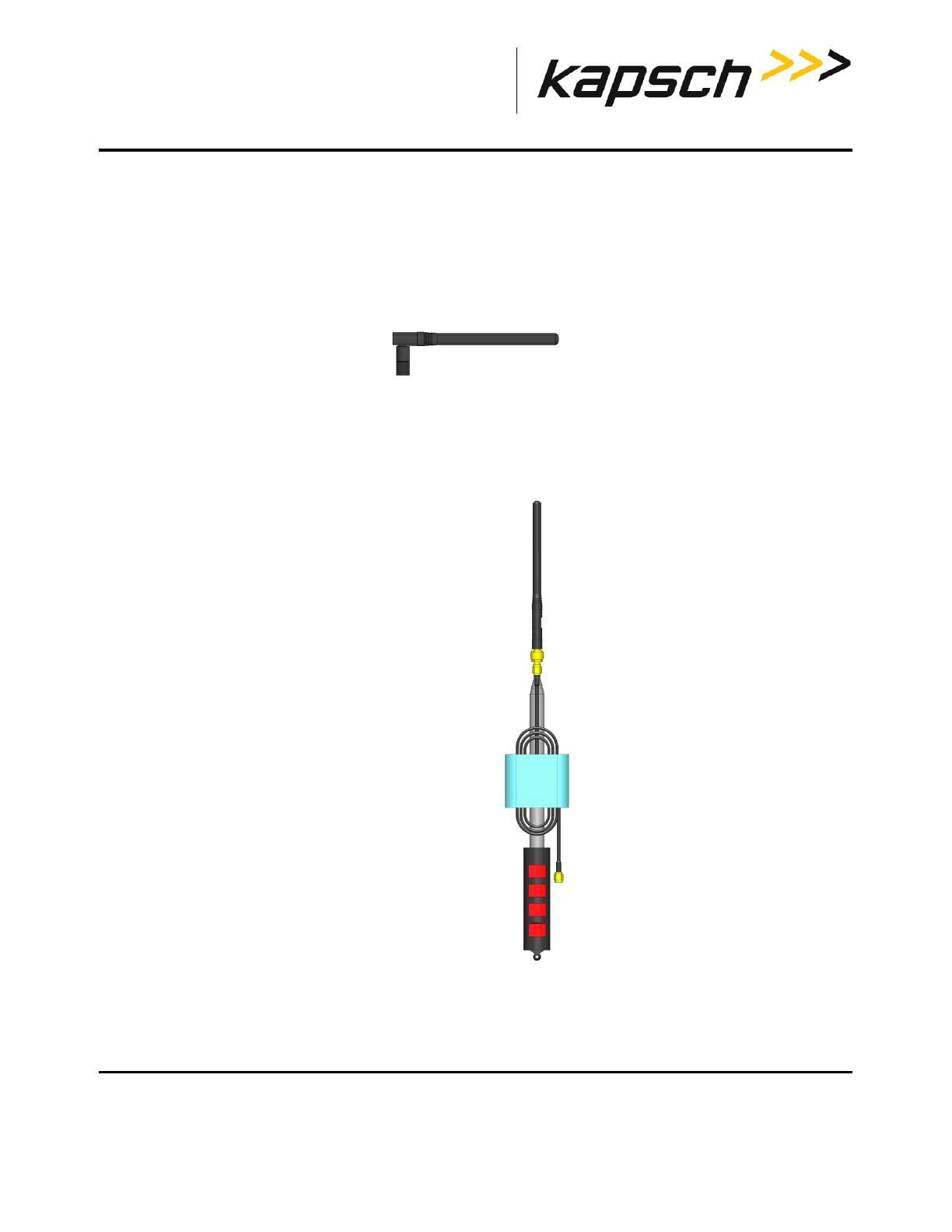
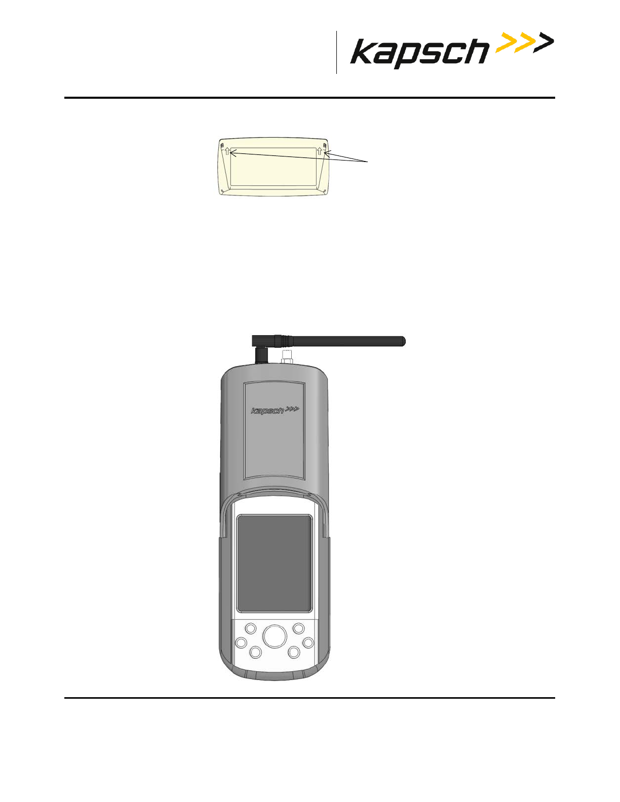
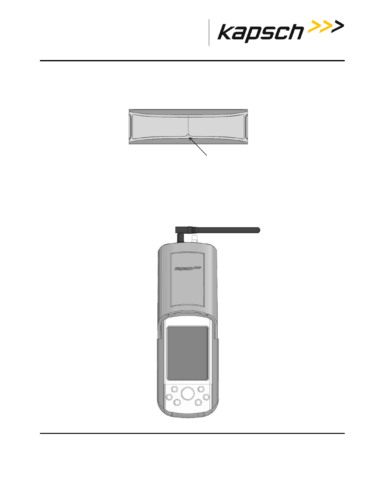
Antennas
The Portable RSE is equipped with a standard locally attached antenna that allows the unit to read Transponders. It
provides a connection for the same type of antenna to be remotely attached via a RF cable for increased distance
from the PDA to the tag. A dedicated terminal is located on the top of the Portable RSE for each type of antenna. The
unused antenna terminal must be terminated with a 50 Ω terminating resistor.
Figure 2-1: Short-Range Antenna
Figure 2-2: Optional remote Antenna
Portable RSE
DOC#: UM 360453-700 REVISION: C Page 12 of 65
© Kapsch TrafficCom Canada Inc. 2013
These drawings and specifications contain confidential and proprietary information and are the property of Kapsch TrafficCom Canada Inc. and are issued in strict confidence
and will be kept confidential and used solely for the purpose intended and for no other purpose and shall not be transmitted, reproduced, copied, and/or used as the basis for
manufacture or sale of apparatus unless otherwise agreed to in writing by Kapsch TrafficCom Canada Inc.
FILE: P-RSE USER MANUAL - UM360453-700 REV_C.DOCX 08/19/2016 1:44
Kapsch TrafficCom
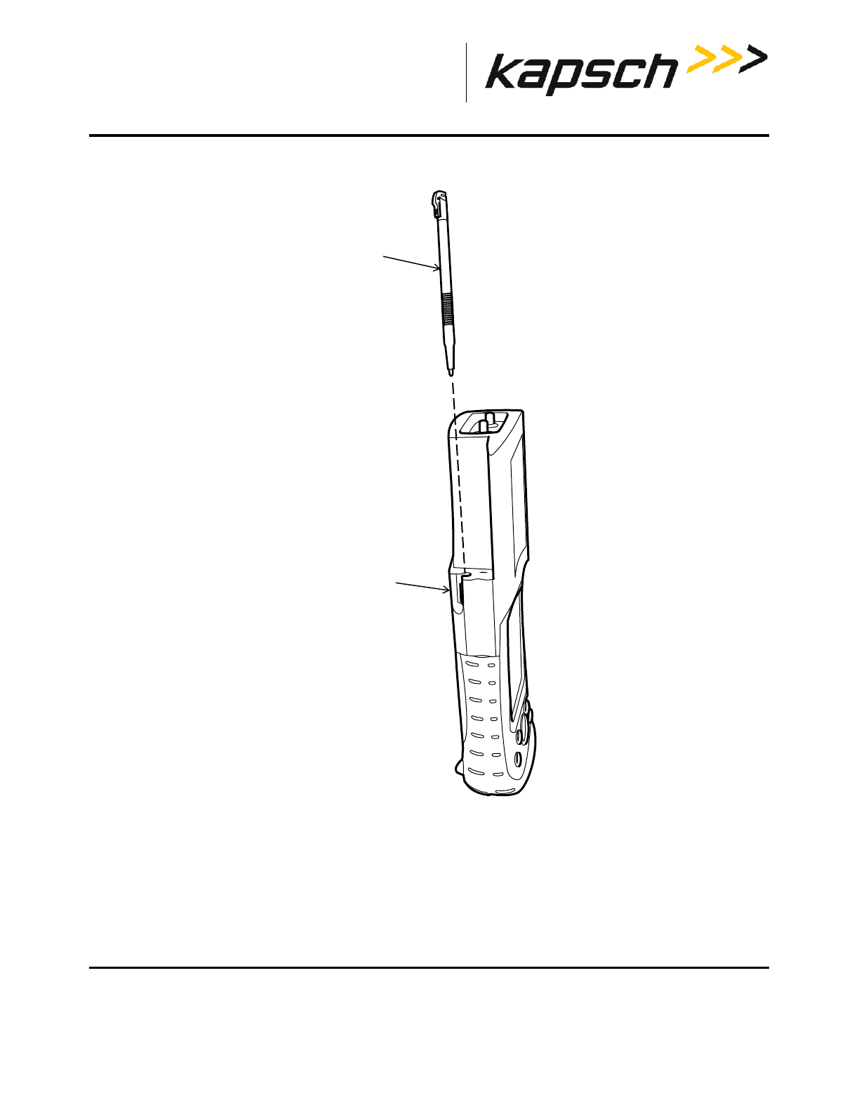
Stylus
CAUTION:
Do not use sharp objects on the Portable RSE touch screen. Tapping the
touch screen with sharp objects can damage the touch screen.
The stylus in Figure 2-3 is stored in the Stylus holder on the back of the device. For best results, it is recommended
that you use the stylus to tap the screen when using the Portable RSE.
Portable RSE
DOC#: UM 360453-700 REVISION: C Page 13 of 65
© Kapsch TrafficCom Canada Inc. 2013
These drawings and specifications contain confidential and proprietary information and are the property of Kapsch TrafficCom Canada Inc. and are issued in strict confidence
and will be kept confidential and used solely for the purpose intended and for no other purpose and shall not be transmitted, reproduced, copied, and/or used as the basis for
manufacture or sale of apparatus unless otherwise agreed to in writing by Kapsch TrafficCom Canada Inc.
FILE: P-RSE USER MANUAL - UM360453-700 REV_C.DOCX 08/19/2016 1:44
Kapsch TrafficCom
Figure 2-3: Portable RSE Stylus
stylus
stylus holder
Portable RSE
DOC#: UM 360453-700 REVISION: C Page 14 of 65
© Kapsch TrafficCom Canada Inc. 2013
These drawings and specifications contain confidential and proprietary information and are the property of Kapsch TrafficCom Canada Inc. and are issued in strict confidence
and will be kept confidential and used solely for the purpose intended and for no other purpose and shall not be transmitted, reproduced, copied, and/or used as the basis for
manufacture or sale of apparatus unless otherwise agreed to in writing by Kapsch TrafficCom Canada Inc.
FILE: P-RSE USER MANUAL - UM360453-700 REV_C.DOCX 08/19/2016 1:44
Kapsch TrafficCom
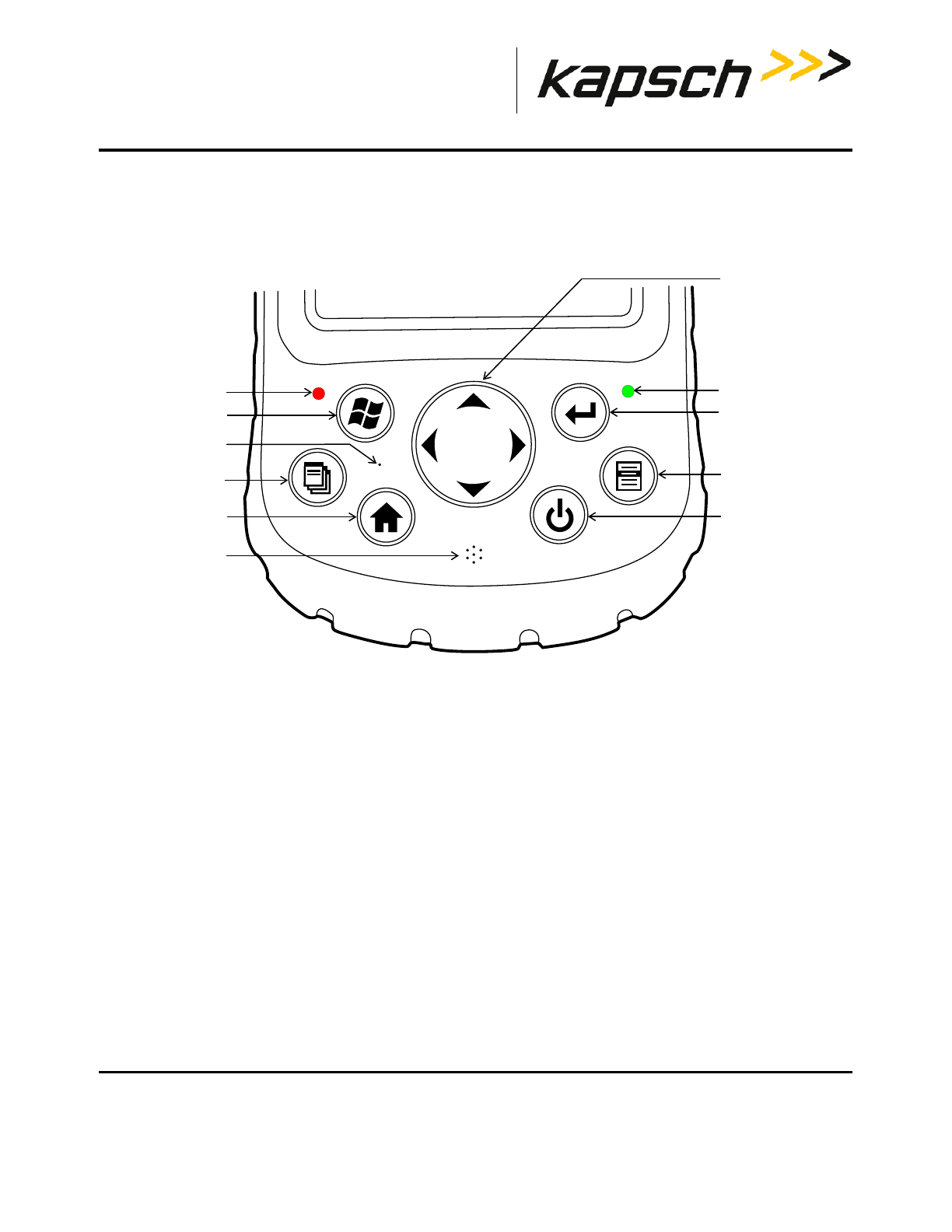
Portable RSE buttons and LEDs
The terms for the buttons and LEDs in Figure 2-4 are used throughout the manual.
Figure 2-4: Portable RSE buttons and LEDs
Power-up LED
Navigation button
Enter button
Context button
Power button
Home button
Start button
Application button
Battery charging LED
Speaker
Microphone
Portable RSE
DOC#: UM 360453-700 REVISION: C Page 15 of 65
© Kapsch TrafficCom Canada Inc. 2013
These drawings and specifications contain confidential and proprietary information and are the property of Kapsch TrafficCom Canada Inc. and are issued in strict confidence
and will be kept confidential and used solely for the purpose intended and for no other purpose and shall not be transmitted, reproduced, copied, and/or used as the basis for
manufacture or sale of apparatus unless otherwise agreed to in writing by Kapsch TrafficCom Canada Inc.
FILE: P-RSE USER MANUAL - UM360453-700 REV_C.DOCX 08/19/2016 1:44
Kapsch TrafficCom
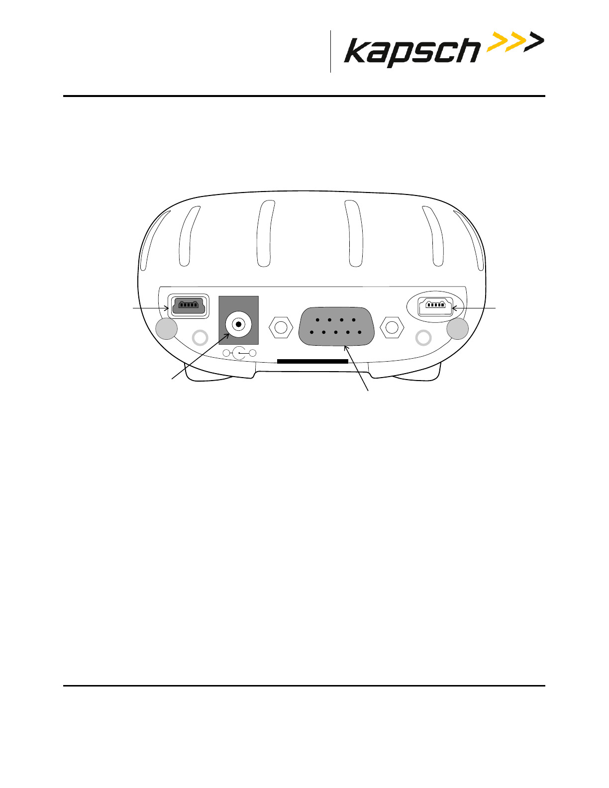
Portable RSE power jack and communication ports
The 12V DC power jack and the communication ports are located on the bottom of the Portable RSE. To protect the
device, ensure the protective cover is properly seated when the ports are not in use.
Figure 2-5: Portable RSE – bottom view
B
12 VDC
0.8A
A
_+
USB mini B port
USB mini A port
(not used)
9-pin serial port
12V DC jack
Portable RSE
DOC#: UM 360453-700 REVISION: C Page 16 of 65
© Kapsch TrafficCom Canada Inc. 2013
These drawings and specifications contain confidential and proprietary information and are the property of Kapsch TrafficCom Canada Inc. and are issued in strict confidence
and will be kept confidential and used solely for the purpose intended and for no other purpose and shall not be transmitted, reproduced, copied, and/or used as the basis for
manufacture or sale of apparatus unless otherwise agreed to in writing by Kapsch TrafficCom Canada Inc.
FILE: P-RSE USER MANUAL - UM360453-700 REV_C.DOCX 08/19/2016 1:44
Kapsch TrafficCom
Charging the Portable RSE battery
CAUTION:
Use only the external power supply intended for the Portable RSE. Using any
other external power source may damage the Portable RSE.
The Portable RSE battery charges via an external power supply connected to the 12VDC jack on the bottom of the
Portable RSE. The Portable RSE battery does not charge when connected to a computer via a USB port. The battery
charging LED flashes red when the battery is charging and illuminates solid red when the battery is fully charged.
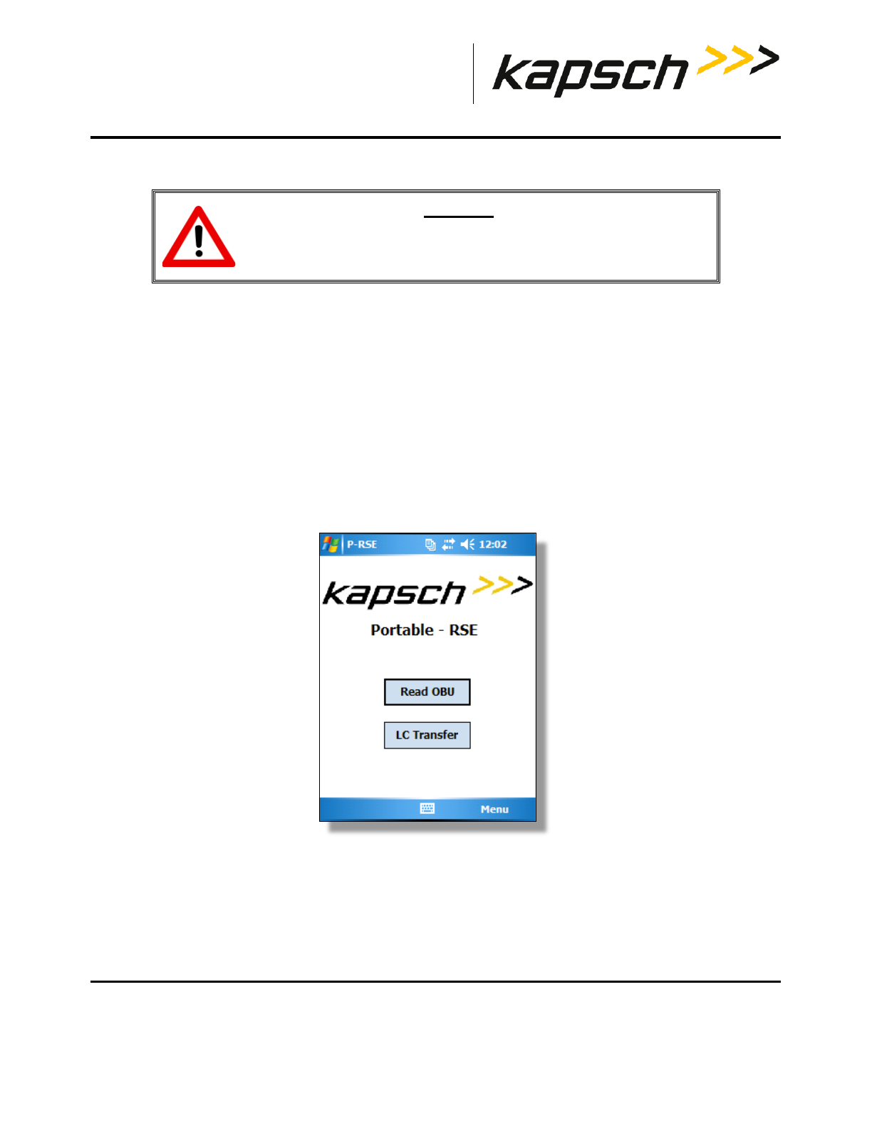
The Portable RSE software interface
The Main menu
When the Portable RSE software launches, the main menu screen appears. From here you can navigate to perform the
Portable RSE’s two main functions: reading OBUs and transferring OBU data to the LC.
Figure 2-6: Main Menu screen
Portable RSE
DOC#: UM 360453-700 REVISION: C Page 17 of 65
© Kapsch TrafficCom Canada Inc. 2013
These drawings and specifications contain confidential and proprietary information and are the property of Kapsch TrafficCom Canada Inc. and are issued in strict confidence
and will be kept confidential and used solely for the purpose intended and for no other purpose and shall not be transmitted, reproduced, copied, and/or used as the basis for
manufacture or sale of apparatus unless otherwise agreed to in writing by Kapsch TrafficCom Canada Inc.
FILE: P-RSE USER MANUAL - UM360453-700 REV_C.DOCX 08/19/2016 1:44
Kapsch TrafficCom
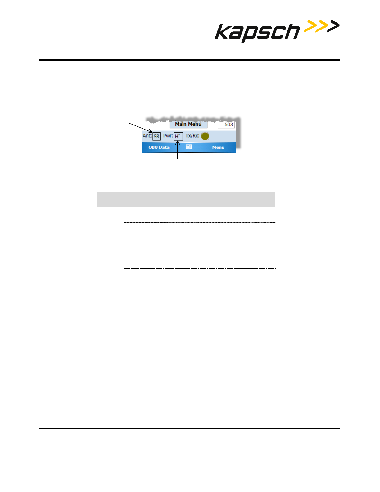
RF Configuration Indication
The RF configuration settings are displayed at the bottom of the OBU Acquisition screen. The abbreviations in Table
2-1 list all possible configuration settings.
Figure 2-7: RF Configuration Display
Table 2-1: RF Configuration Abbreviations
Antenna Type
RF Power Level
State Indicator Meaning
Ant SR short-range antenna selected
LR long-range antenna port selected
Pwr LO low RF power level selected
MD medium RF power level selected
HI high RF power level selected
AU automatic RF power level selected

Portable RSE
DOC#: UM 360453-700 REVISION: C Page 18 of 65
© Kapsch TrafficCom Canada Inc. 2013
These drawings and specifications contain confidential and proprietary information and are the property of Kapsch TrafficCom Canada Inc. and are issued in strict confidence
and will be kept confidential and used solely for the purpose intended and for no other purpose and shall not be transmitted, reproduced, copied, and/or used as the basis for
manufacture or sale of apparatus unless otherwise agreed to in writing by Kapsch TrafficCom Canada Inc.
FILE: P-RSE USER MANUAL - UM360453-700 REV_C.DOCX 08/19/2016 1:44
Kapsch TrafficCom
Tx/Rx indicator
The Tx/Rx indicator on the bottom of the LC Transfer screen and the OBU Acquisition screen provides the following
feedback:
Table 2-2: Tx/Rx indicator states
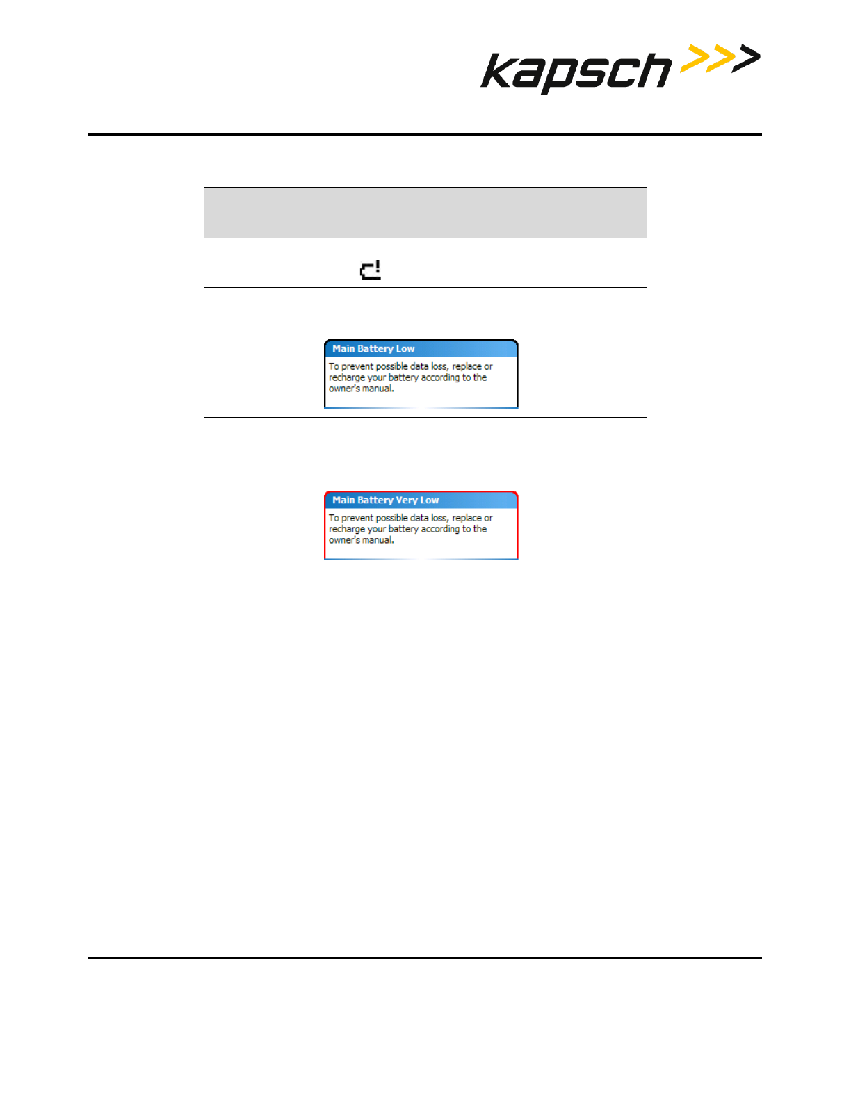
Low battery level indication and effects on Portable RSE
A low battery level can affect the performance of the Portable RSE as the device attempts to reduce power
consumption and avoid data loss. Table 2-3 outlines the behavior you can expect as the remaining battery power is
reduced.
State Meaning Screen
(Dk Green)
Portable RSE connection to LC is idle. LC Transfer
(Lt.Green)
Portable RSE is transferring data to the
LC.
LC Transfer
(clear)
Portable RSE communication with OBU is
idle.
OBU Acquisition
Health Check is idle. Diagnostics
(Yellow)
Portable RSE is attempting to
communicate with OBU.
OBU Acquisition
The Portable RSE is performing a Health
Check.
Diagnostics
Portable RSE
DOC#: UM 360453-700 REVISION: C Page 19 of 65
© Kapsch TrafficCom Canada Inc. 2013
These drawings and specifications contain confidential and proprietary information and are the property of Kapsch TrafficCom Canada Inc. and are issued in strict confidence
and will be kept confidential and used solely for the purpose intended and for no other purpose and shall not be transmitted, reproduced, copied, and/or used as the basis for
manufacture or sale of apparatus unless otherwise agreed to in writing by Kapsch TrafficCom Canada Inc.
FILE: P-RSE USER MANUAL - UM360453-700 REV_C.DOCX 08/19/2016 1:44
Kapsch TrafficCom
Table 2-3: Low battery level indicators
OBU data fields
OBU data is displayed on the OBU Acquisition screen, the Agency screen, and the Scratchpad screen:
approximate
battery level effect on RSE (if not connected to AC power)
20% • battery level indicator bars replaced by exclamation
mark:
15% • The RSE suspends into Hibernate mode after 1 min.
• Main Battery Low warning message appears:
10% • The RSE suspends into sleep mode after 10 sec.
• Cannot transfer OBU data to the LC.
• Main Battery Very Low warning message appears.

Portable RSE
DOC#: UM 360453-700 REVISION: C Page 20 of 65
© Kapsch TrafficCom Canada Inc. 2013
These drawings and specifications contain confidential and proprietary information and are the property of Kapsch TrafficCom Canada Inc. and are issued in strict confidence
and will be kept confidential and used solely for the purpose intended and for no other purpose and shall not be transmitted, reproduced, copied, and/or used as the basis for
manufacture or sale of apparatus unless otherwise agreed to in writing by Kapsch TrafficCom Canada Inc.
FILE: P-RSE USER MANUAL - UM360453-700 REV_C.DOCX 08/19/2016 1:44
Kapsch TrafficCom
Table 2-4 OBU data fields and locations
Data Field Screen where data appear
Date/Time OBU Acquisition
Status OBU Acquisition
Agency ID OBU Acquisition
OBU Serial # OBU Acquisition
OBU Type OBU Acquisition
Revenue Type Agency
(De-)Commission Agency
Mounting Loc Agency
Veh. Type Agency
Veh. Axles Agency
Veh. Weight Agency
Veh. Rear Tires Agency
Reader ID Scratchpad
TM Date/Time Scratchpad
Plaza ID Scratchpad
Lane ID Scratchpad
TC Date/Time Scratchpad
Txn Num Scratchpad
Checksum Scratchpad
Agency ID Scratchpad
Portable RSE
DOC#: UM 360453-700 REVISION: C Page 21 of 65
© Kapsch TrafficCom Canada Inc. 2013
These drawings and specifications contain confidential and proprietary information and are the property of Kapsch TrafficCom Canada Inc. and are issued in strict confidence
and will be kept confidential and used solely for the purpose intended and for no other purpose and shall not be transmitted, reproduced, copied, and/or used as the basis for
manufacture or sale of apparatus unless otherwise agreed to in writing by Kapsch TrafficCom Canada Inc.
FILE: P-RSE USER MANUAL - UM360453-700 REV_C.DOCX 08/19/2016 1:44
Kapsch TrafficCom
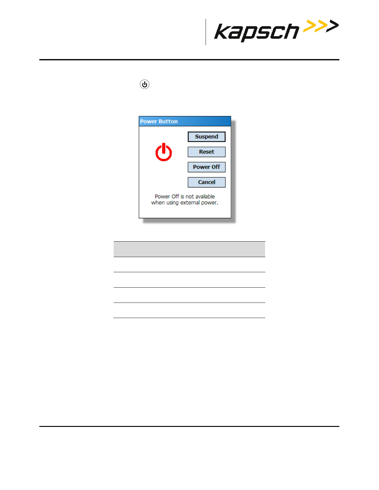
Power Button menu
Pressing and holding the Power button will open the Power Button menu. From this menu, there are several
shutdown options available, as outlined in Table 2-5.
Figure 2-8: Power Button menu
Table 2-5: Available functions on Power Button menu
Button Function
Suspend puts the unit in Hibernate mode.
Reset reboots the Portable RSE.
Power Off shuts down the Portable RSE.
Cancel closes the Power Button menu.
Portable RSE
DOC#: UM 360453-700 REVISION: C Page 22 of 65
© Kapsch TrafficCom Canada Inc. 2013
These drawings and specifications contain confidential and proprietary information and are the property of Kapsch TrafficCom Canada Inc. and are issued in strict confidence
and will be kept confidential and used solely for the purpose intended and for no other purpose and shall not be transmitted, reproduced, copied, and/or used as the basis for
manufacture or sale of apparatus unless otherwise agreed to in writing by Kapsch TrafficCom Canada Inc.
FILE: P-RSE USER MANUAL - UM360453-700 REV_C.DOCX 08/19/2016 1:44
Kapsch TrafficCom
How the Portable RSE works
When an OBU read is initiated, the Portable RSE scans for any IAG-protocol OBUs within range. OBUs within range
respond by transmitting their data to the Portable RSE. This data is then decoded and displayed on the LCD. The
Portable RSE includes a standard whip antenna that allows the unit to read OBUs at a distance of approximately 5
feet. An optional remote antenna is available that can extend the reach of the device to approximately 9 feet. The
Portable RSE does not write to the OBU.
Data Storage
The data read by the Portable RSE is stored internally in the Portable RSE where it can be either be viewed or
downloaded to the LC. The Portable RSE can store data from a maximum of 1000 OBU reads. Once 1000 OBUs have
been read, the data must be downloaded to an LC or erased before more OBUs can be read. OBU data is automatically
erased from the Portable RSE once it has been downloaded to the LC. See Erasing OBU data on page 38 for more
information.
Synchronization
When performing a read, the Portable RSE checks for incoming RF signals from toll plaza Readers. If trigger pulses
from toll plaza Readers are detected, the Portable RSE determines the length of time between trigger pulses (i.e. the
length of the superframe) and sends its own trigger pulse when it is unlikely to conflict with the toll plaza Reader. This
ensures data is not corrupted in either the Portable RSE or toll plaza Readers.
Note: To avoid potential performance impacts on toll plaza Readers, the Portable
RSE must be positioned in accordance with the requirements of this section.
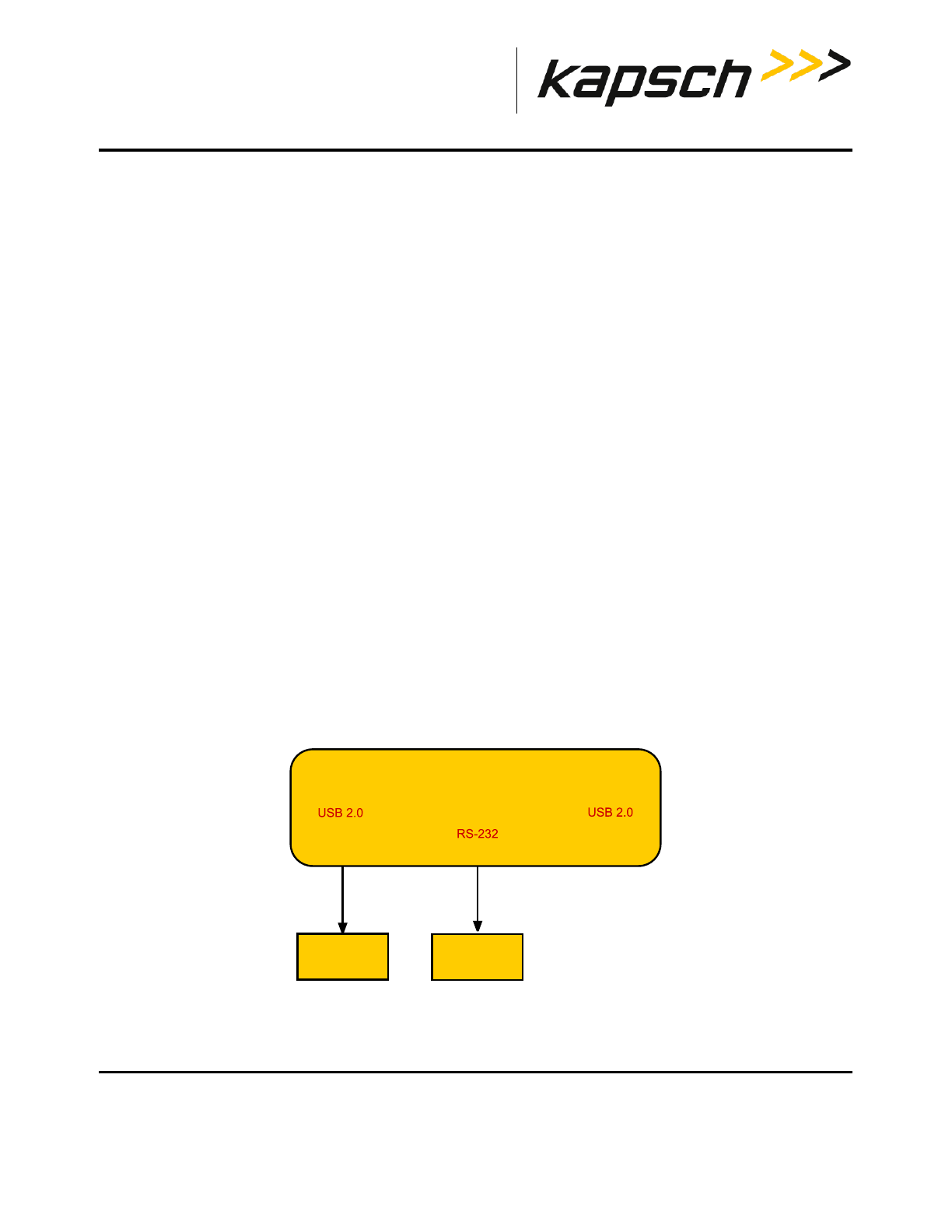
RSE Communication block diagram
Figure 2-9 illustrates the possible external communication interfaces of the Portable RSE.
Figure 2-9: RSE communication block diagram
P-RSE
USB mini-B
port serial port
Lane
Controller
USB mini-A
port
not used
Computer

Portable RSE
DOC#: UM 360453-700 REVISION: C Page 23 of 65
© Kapsch TrafficCom Canada Inc. 2013
These drawings and specifications contain confidential and proprietary information and are the property of Kapsch TrafficCom Canada Inc. and are issued in strict confidence
and will be kept confidential and used solely for the purpose intended and for no other purpose and shall not be transmitted, reproduced, copied, and/or used as the basis for
manufacture or sale of apparatus unless otherwise agreed to in writing by Kapsch TrafficCom Canada Inc.
FILE: P-RSE USER MANUAL - UM360453-700 REV_C.DOCX 08/19/2016 1:44
Kapsch TrafficCom
3. OPERATING PROCEDURES
Starting up the Portable RSE
This procedure outlines how to power up the Portable RSE.
Prerequisites: None.
NOTE: The Portable RSE will automatically start up when connected to external AC
power.
1. Press the Power button .The green power-up LED lights for approximately 10 seconds while the Portable RSE
begins booting up.
2. The Ultra-Rugged Field PC and Windows Mobile boot splash screens appear. After Windows Mobile has started,
the Portable RSE software automatically launches.
3. A Health Check is automatically performed and messages are displayed if any errors are found. Total boot-up time
is approximately one (1) minute.
Suspending the Portable RSE
Suspending the device does not shut down the Portable RSE or end any programs, but puts the Portable RSE into
Hibernate mode. In Hibernate mode, the LCD screen goes completely blank. Hibernate mode reduces, but does not
eliminate, battery power consumption. This procedure outlines how to manually suspend the Portable RSE; however,
you can also configure the Portable RSE to automatically suspend after a predetermined time (see Configuring
automatic suspending, page 49).
Prerequisites: None.
1. Press the Power button . The green power-up LED lights momentarily and the screen powers off.
Waking the Portable RSE
This procedure outlines how to activate a suspended Portable RSE from Hibernate mode.
Prerequisites: None.
1. Press the Power button . The green power-up LED lights momentarily and the Portable RSE displays the screen
showing at the time the Portable RSE was suspended.

Portable RSE
DOC#: UM 360453-700 REVISION: C Page 24 of 65
© Kapsch TrafficCom Canada Inc. 2013
These drawings and specifications contain confidential and proprietary information and are the property of Kapsch TrafficCom Canada Inc. and are issued in strict confidence
and will be kept confidential and used solely for the purpose intended and for no other purpose and shall not be transmitted, reproduced, copied, and/or used as the basis for
manufacture or sale of apparatus unless otherwise agreed to in writing by Kapsch TrafficCom Canada Inc.
FILE: P-RSE USER MANUAL - UM360453-700 REV_C.DOCX 08/19/2016 1:44
Kapsch TrafficCom
Powering off the Portable RSE
Powering off the Portable RSE ends all programs and removes power from all Portable RSE components except for the
internal real-time clock. The Portable RSE should be powered off if it will not be used for an extended period of time.
No OBU data or configuration settings are lost when the Portable RSE is powered off.
Prerequisites: The Portable RSE must be disconnected from AC power.
1. Press and hold the Power button until the Power Button menu appears.
2. From the Power Button menu, press the Power Off button. The Power Off button will not be available if the RSE
is charging.
3. A warning message appears, stating that unsaved data will be lost. Select OK. No OBU data is lost when the RSE is
powered off.
Resetting (Rebooting) the Portable RSE
Reboot the Portable RSE by tapping Reset from the Power Button menu, or by holding down the Power button
for approx. 6 sec. No OBU data or configuration settings are lost when the Portable RSE is rebooted.
Prerequisites: None.
1. Press and hold the Power button until the Power Button menu appears.
2. From the Power Button menu, press the Reset button; or continue to hold the Power button for approx. 6 sec.
until the Portable RSE reboots.
Portable RSE
DOC#: UM 360453-700 REVISION: C Page 25 of 65
© Kapsch TrafficCom Canada Inc. 2013
These drawings and specifications contain confidential and proprietary information and are the property of Kapsch TrafficCom Canada Inc. and are issued in strict confidence
and will be kept confidential and used solely for the purpose intended and for no other purpose and shall not be transmitted, reproduced, copied, and/or used as the basis for
manufacture or sale of apparatus unless otherwise agreed to in writing by Kapsch TrafficCom Canada Inc.
FILE: P-RSE USER MANUAL - UM360453-700 REV_C.DOCX 08/19/2016 1:44
Kapsch TrafficCom
Checking battery power remaining
Two types of battery power remaining indications are available: general and detailed. You should be aware of how
much battery power is remaining, as low battery power levels can affect the behavior of the Portable RSE (see Low
battery level indication and effects on Portable RSE, page 18).
Note: For low battery indications see Table 2-3: Low battery level indicators on page 19.
Prerequisites: None.
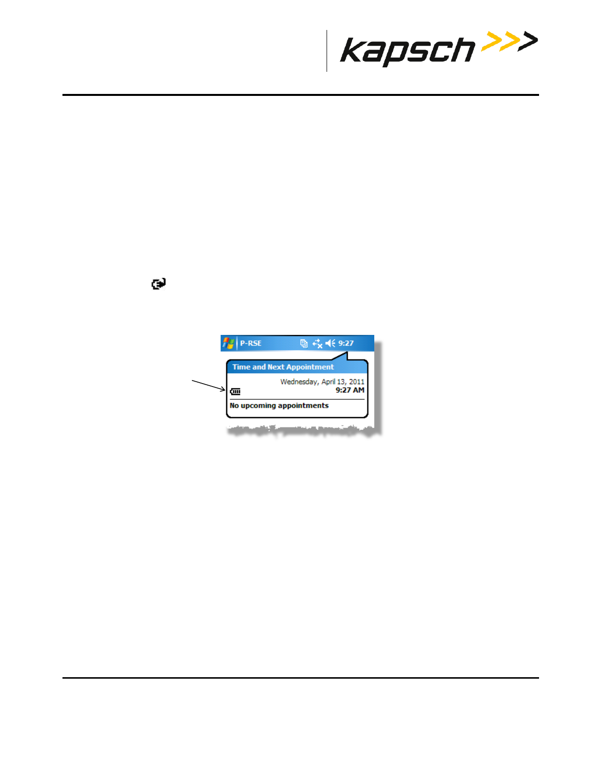
Viewing the general battery level
1. Tap the time displayed in the upper-right corner of any screen.
2. If the Portable RSE is running on battery power, the battery level is shown between 1 to 4 bars, with an
exclamation mark indicating a low battery level. If the Portable RSE is running on AC power, a power cord
connection icon is displayed. To view the battery power level remaining while connected to AC power,
perform step 3.
Figure 3-1: General battery power level indication
battery level indicator
Portable RSE
DOC#: UM 360453-700 REVISION: C Page 26 of 65
© Kapsch TrafficCom Canada Inc. 2013
These drawings and specifications contain confidential and proprietary information and are the property of Kapsch TrafficCom Canada Inc. and are issued in strict confidence
and will be kept confidential and used solely for the purpose intended and for no other purpose and shall not be transmitted, reproduced, copied, and/or used as the basis for
manufacture or sale of apparatus unless otherwise agreed to in writing by Kapsch TrafficCom Canada Inc.
FILE: P-RSE USER MANUAL - UM360453-700 REV_C.DOCX 08/19/2016 1:44
Kapsch TrafficCom
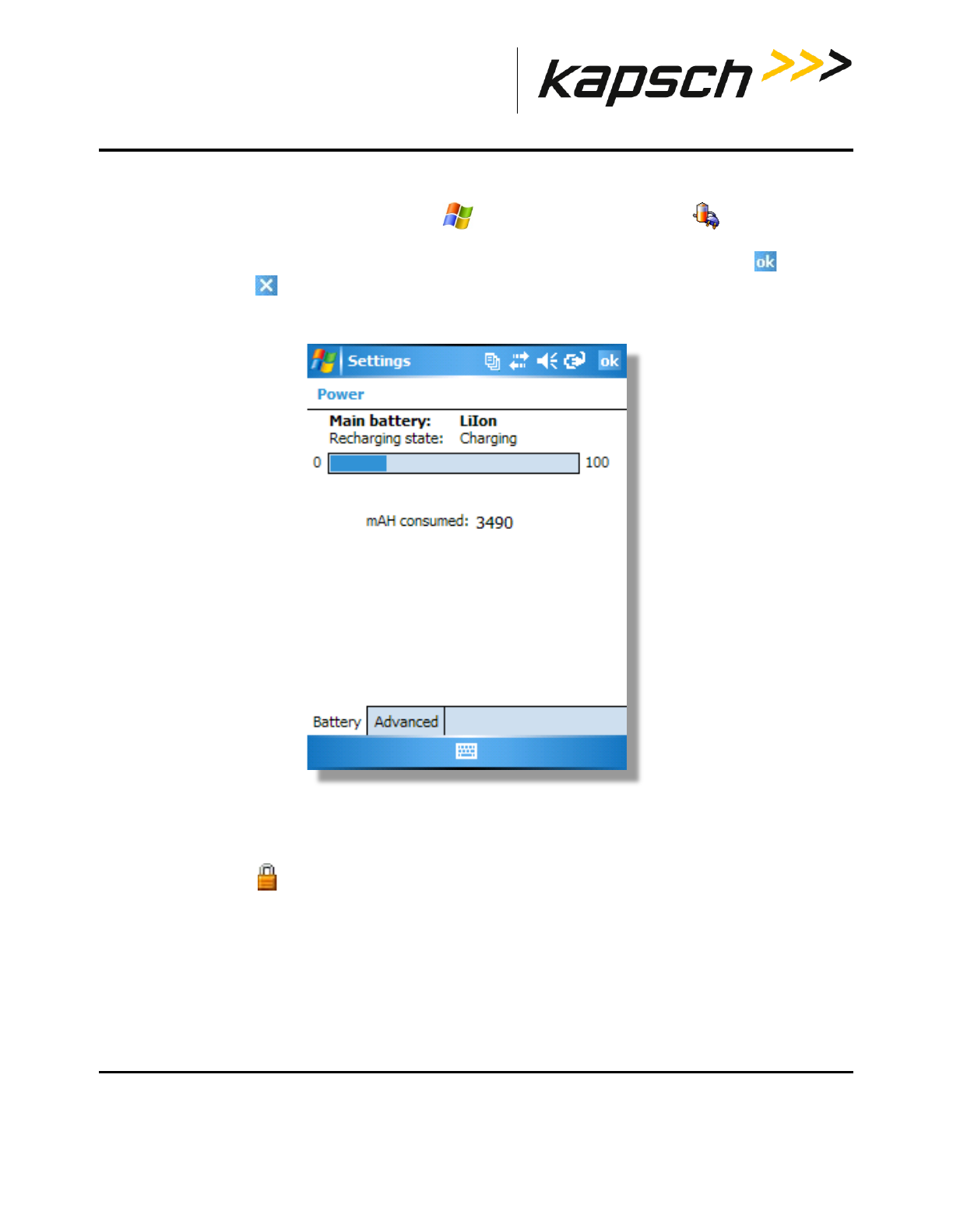
Viewing the detailed battery level
3. For a more detailed battery level indication, Tap Settings System tabPower . Battery tab. The
battery power level is shown in a bar graph, and the total mAH consumed. 0 mAH consumed indicates the battery
is 100% charged while 3900 mAH consumed indicates the battery is completely depleted. Tap to exit the
Power screen, then to return to the Portable RSE software.
Figure 3-2: Detailed battery power level indication
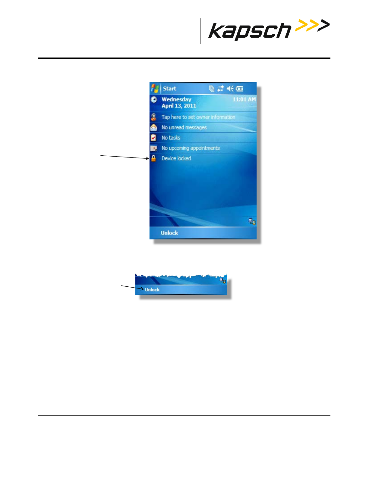
Unlocking the Portable RSE
If you inadvertently lock the Portable RSE from the Windows Mobile Today screen, the RSE will not accept any
inputs and you will not be able to navigate from the Today screen.
Portable RSE
DOC#: UM 360453-700 REVISION: C Page 27 of 65
© Kapsch TrafficCom Canada Inc. 2013
These drawings and specifications contain confidential and proprietary information and are the property of Kapsch TrafficCom Canada Inc. and are issued in strict confidence
and will be kept confidential and used solely for the purpose intended and for no other purpose and shall not be transmitted, reproduced, copied, and/or used as the basis for
manufacture or sale of apparatus unless otherwise agreed to in writing by Kapsch TrafficCom Canada Inc.
FILE: P-RSE USER MANUAL - UM360453-700 REV_C.DOCX 08/19/2016 1:44
Kapsch TrafficCom
Figure 3-3: Windows Mobile 5.0 locked Today screen
1. Unlock the RSE.
a) Tap Unlock at the bottom-right of the screen. The Unlock screen appears
b) Tap Unlock from the Unlock screen.
locked Portable RSE
indication
tap Unlock

Portable RSE
DOC#: UM 360453-700 REVISION: C Page 28 of 65
© Kapsch TrafficCom Canada Inc. 2013
These drawings and specifications contain confidential and proprietary information and are the property of Kapsch TrafficCom Canada Inc. and are issued in strict confidence
and will be kept confidential and used solely for the purpose intended and for no other purpose and shall not be transmitted, reproduced, copied, and/or used as the basis for
manufacture or sale of apparatus unless otherwise agreed to in writing by Kapsch TrafficCom Canada Inc.
FILE: P-RSE USER MANUAL - UM360453-700 REV_C.DOCX 08/19/2016 1:44
Kapsch TrafficCom
2. The device is now unlocked . To return to the Portable RSE software, see Returning to the Portable RSE
program, page 28.
Returning to the Portable RSE program
Although the Portable RSE runs on the Windows Mobile 5.0 operating system, the Portable RSE is not meant as a
personal computing device. You should keep the Portable RSE software active at all times. However, if you
inadvertently close the Portable RSE software screen, you can easily return to it:
1. Press the Power button to suspend the RSE.
2. Press the Power button again to wake the RSE. The RSE will automatically return to the RSE software.
3. If the RSE does not return to the RSE software, you must restart the RSE software (see Restart the Portable RSE
software, page 28).
Restart the Portable RSE software
If you inadvertently shutdown the RSE software, reboot the Portable RSE (see Resetting (Rebooting) the Portable RSE,
page 24) to restart the RSE software. No OBU data is lost when the RSE is rebooted.
Portable RSE
DOC#: UM 360453-700 REVISION: C Page 29 of 65
© Kapsch TrafficCom Canada Inc. 2013
These drawings and specifications contain confidential and proprietary information and are the property of Kapsch TrafficCom Canada Inc. and are issued in strict confidence
and will be kept confidential and used solely for the purpose intended and for no other purpose and shall not be transmitted, reproduced, copied, and/or used as the basis for
manufacture or sale of apparatus unless otherwise agreed to in writing by Kapsch TrafficCom Canada Inc.
FILE: P-RSE USER MANUAL - UM360453-700 REV_C.DOCX 08/19/2016 1:44
Kapsch TrafficCom
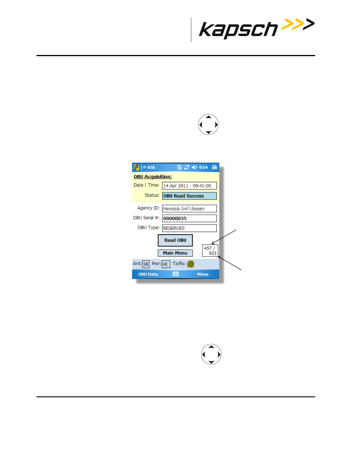
Reading OBUs
OBUs are read from the OBU Acquisition screen.
Prerequisites: - The Portable RSE must have less than 1000 stored OBU records.
- The Portable RSE antenna is properly installed and configured (see Installing an antenna, page48).
- The Portable RSE must be positioned within the scanning zone (see Scanning Zones, page 30).
- Only one OBU must be within range of the Portable RSE.
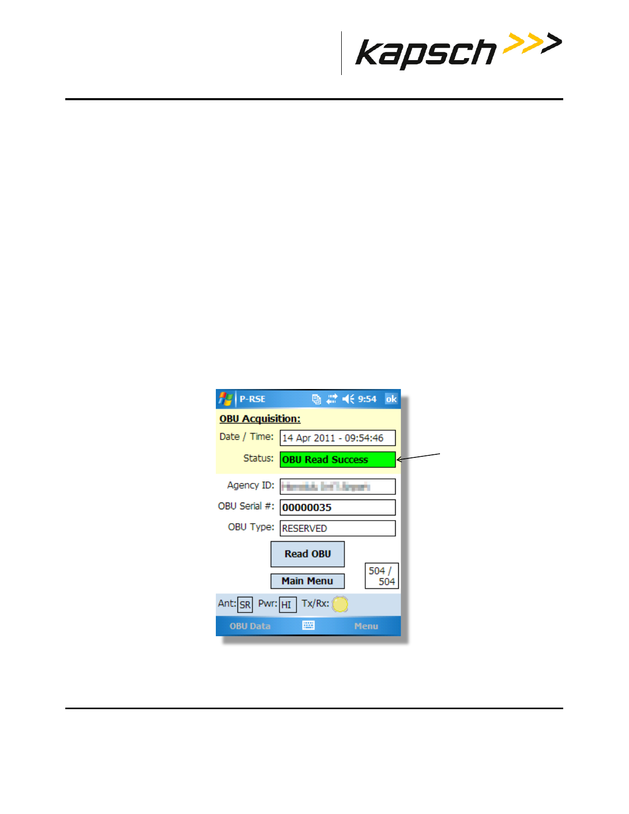
1. From the Portable RSE main menu, tap Read OBU. The OBU Acquisition screen appears.
2. With the Portable RSE orientated as outlined in Scanning Zones, page 30, from the OBU Acquisition screen, tap
Read OBU.
NOTE: A blue highlighted OBU Read Success message indicates saved OBU data is
being displayed. A green highlighted OBU Read Success message indicates
data from the latest OBU read is being displayed.
3. After approx. 1 or 2 seconds, the Read result status is displayed. If OBU Read Success is displayed, the OBU data
has been successfully read. Any other message indicates a Read error. See Table 3-1, page 30.
Figure 3-4: Successful OBU scan
Read result status

Portable RSE
DOC#: UM 360453-700 REVISION: C Page 30 of 65
© Kapsch TrafficCom Canada Inc. 2013
These drawings and specifications contain confidential and proprietary information and are the property of Kapsch TrafficCom Canada Inc. and are issued in strict confidence
and will be kept confidential and used solely for the purpose intended and for no other purpose and shall not be transmitted, reproduced, copied, and/or used as the basis for
manufacture or sale of apparatus unless otherwise agreed to in writing by Kapsch TrafficCom Canada Inc.
FILE: P-RSE USER MANUAL - UM360453-700 REV_C.DOCX 08/19/2016 1:44
Kapsch TrafficCom
Table 3-1: Possible OBU Read result statuses and solutions
Read Status Description Solution
OBU Read Success The OBU was read successfully. N/A
OBU Data Not Read The Portable RSE did not receive any
OBU data and was unable to
communicate with the OBU.
Ensure the prerequisites for Reading OBUs
on page 29 have been met.
CRC error Invalid CRC. Ensure the prerequisites for Reading OBUs
on page 29 have been met.
Non-IAG OBU The OBU has a non-IAG Group ID. The data are read and stored as in a Read
Success unless it is also detected that the
OBU is not supported.
OBU not supported The Portable RSE is not permitted to
accept data from OBUs of this particular
Group ID.
The list of unaccepted Group Ids is factory
configured. Contact Kapsch TrafficCom if
this Group ID has been excluded in error.
Comms Error The Portable RSE could not read all the
OBU data in the allotted time.
Ensure the prerequisites for Reading OBUs
on page 29 have been met. Also, see Table
6-1: Health Check Status Results.
Portable RSE
DOC#: UM 360453-700 REVISION: C Page 31 of 65
© Kapsch TrafficCom Canada Inc. 2013
These drawings and specifications contain confidential and proprietary information and are the property of Kapsch TrafficCom Canada Inc. and are issued in strict confidence
and will be kept confidential and used solely for the purpose intended and for no other purpose and shall not be transmitted, reproduced, copied, and/or used as the basis for
manufacture or sale of apparatus unless otherwise agreed to in writing by Kapsch TrafficCom Canada Inc.
FILE: P-RSE USER MANUAL - UM360453-700 REV_C.DOCX 08/19/2016 1:44
Kapsch TrafficCom
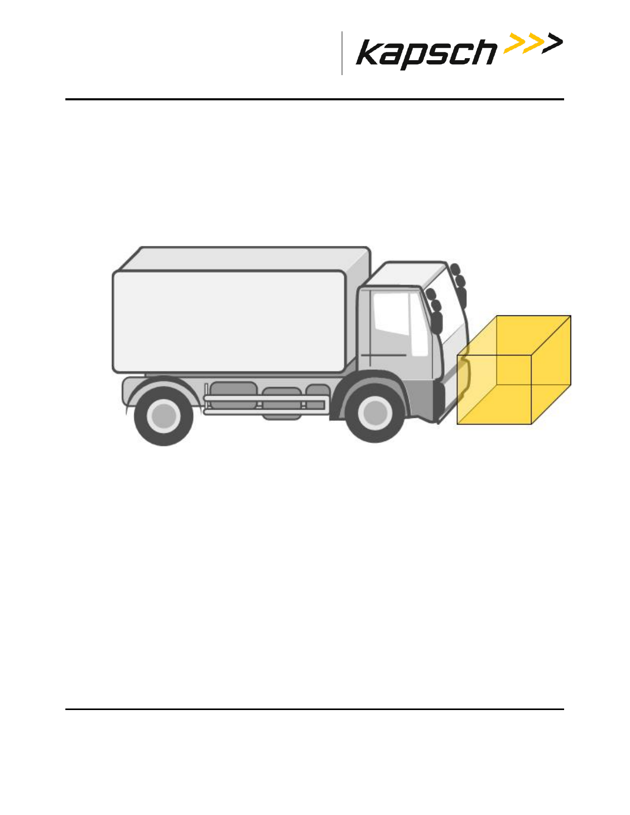
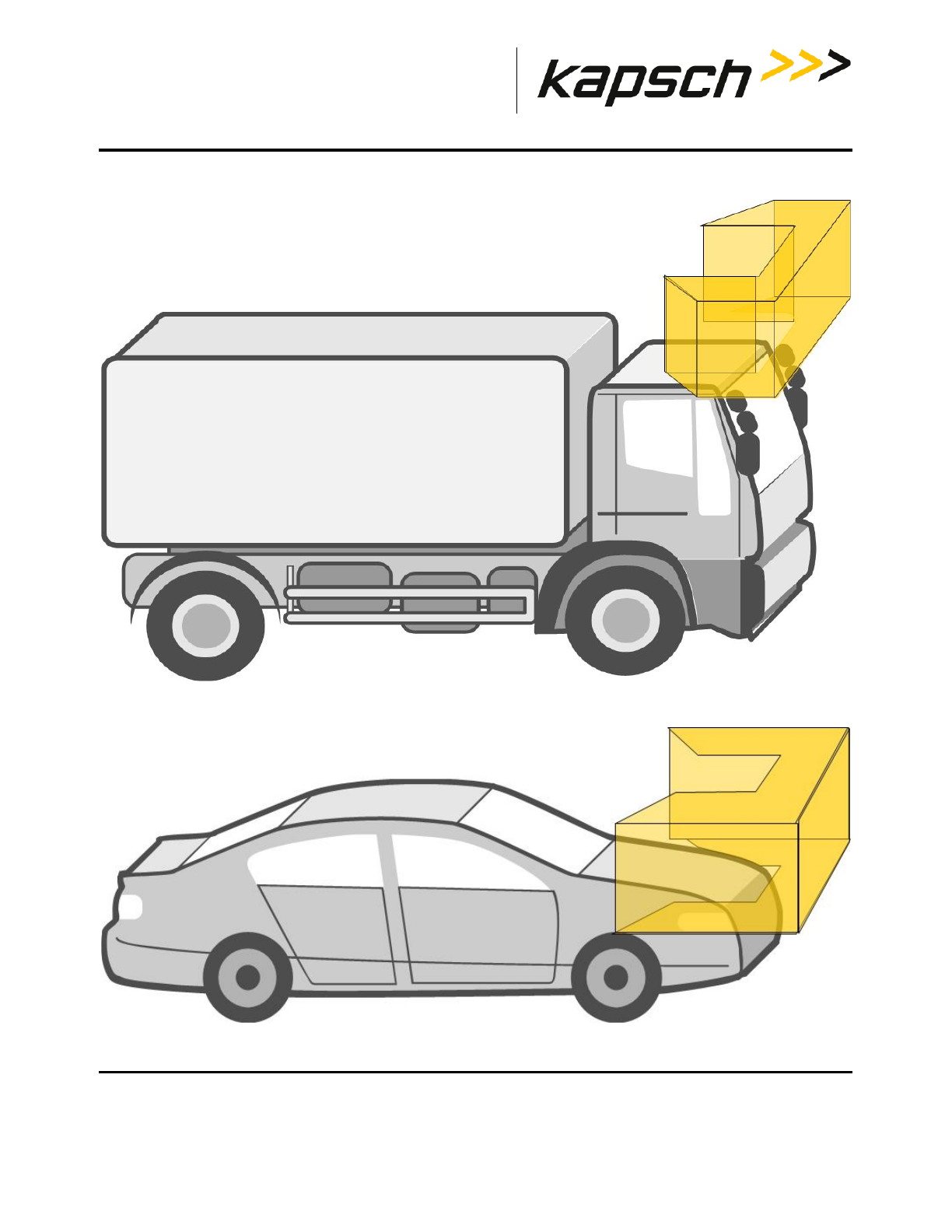
Scanning Zones
When scanning mounted OBUs, position yourself facing the OBU with the Portable RSE held in front of you. The
distance between the Portable RSE and the OBU is controlled by the configuration. The short-range antenna has a
maximum range of 5 feet. The ideal position for a successful read is to position the Portable RSE in the shaded areas in
the two diagrams below.
Front-Mounted OBUs on Trucks
Portable RSE
DOC#: UM 360453-700 REVISION: C Page 32 of 65
© Kapsch TrafficCom Canada Inc. 2013
These drawings and specifications contain confidential and proprietary information and are the property of Kapsch TrafficCom Canada Inc. and are issued in strict confidence
and will be kept confidential and used solely for the purpose intended and for no other purpose and shall not be transmitted, reproduced, copied, and/or used as the basis for
manufacture or sale of apparatus unless otherwise agreed to in writing by Kapsch TrafficCom Canada Inc.
FILE: P-RSE USER MANUAL - UM360453-700 REV_C.DOCX 08/19/2016 1:44
Kapsch TrafficCom
Roof-Mounted OBUs on Trucks
Windshield-Mounted OBUs on Passenger Vehicles
Portable RSE
DOC#: UM 360453-700 REVISION: C Page 33 of 65
© Kapsch TrafficCom Canada Inc. 2013
These drawings and specifications contain confidential and proprietary information and are the property of Kapsch TrafficCom Canada Inc. and are issued in strict confidence
and will be kept confidential and used solely for the purpose intended and for no other purpose and shall not be transmitted, reproduced, copied, and/or used as the basis for
manufacture or sale of apparatus unless otherwise agreed to in writing by Kapsch TrafficCom Canada Inc.
FILE: P-RSE USER MANUAL - UM360453-700 REV_C.DOCX 08/19/2016 1:44
Kapsch TrafficCom
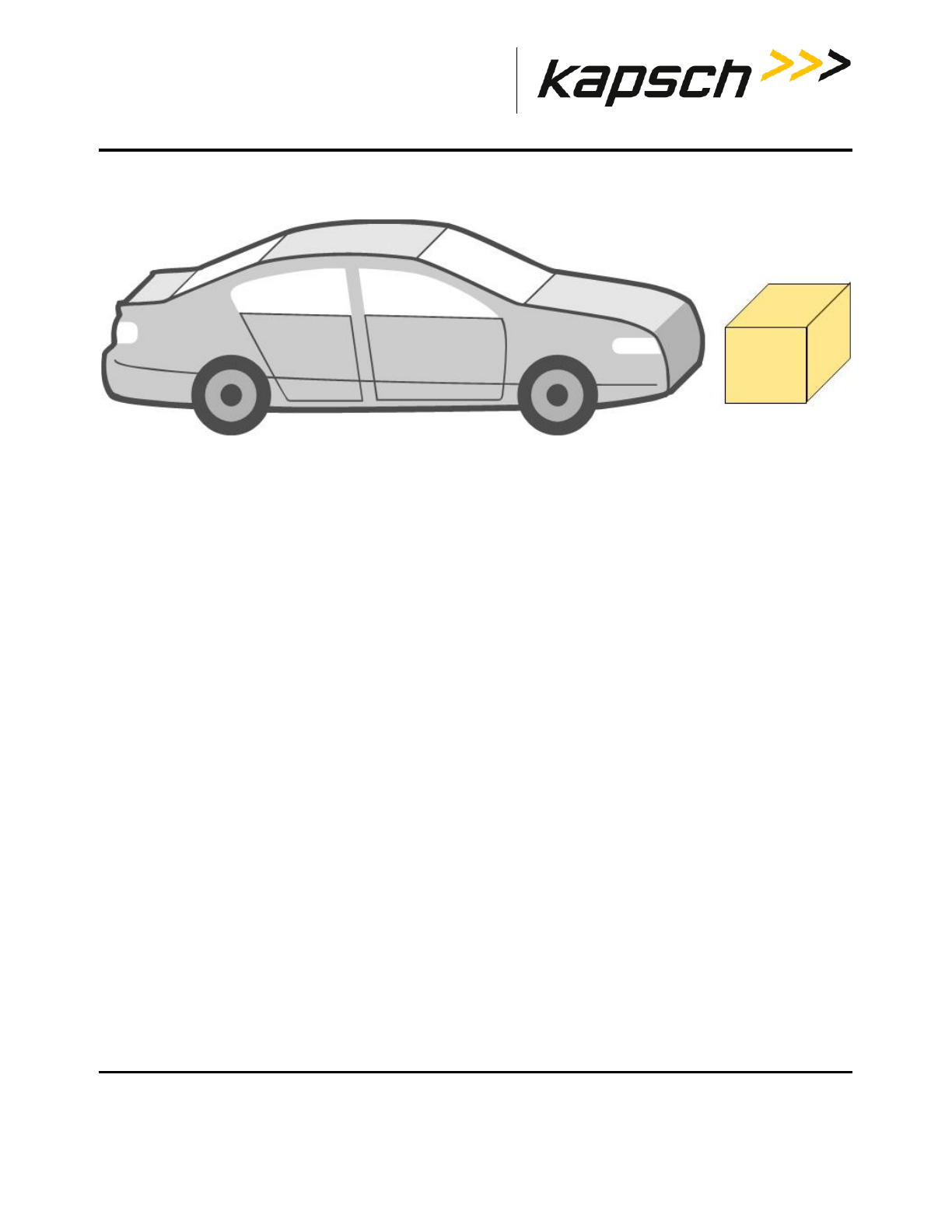
Front-Mounted OBUs on Passenger Vehicles
Unmounted OBUs
For OBUs that are not installed in a vehicle, scan the OBUs in the orientation and approximate distance outlined
below.
For unmounted FME, FPT, and G4 OBUs, orient the OBU with the arrows pointing away from the Portable RSE.
Portable RSE
DOC#: UM 360453-700 REVISION: C Page 34 of 65
© Kapsch TrafficCom Canada Inc. 2013
These drawings and specifications contain confidential and proprietary information and are the property of Kapsch TrafficCom Canada Inc. and are issued in strict confidence
and will be kept confidential and used solely for the purpose intended and for no other purpose and shall not be transmitted, reproduced, copied, and/or used as the basis for
manufacture or sale of apparatus unless otherwise agreed to in writing by Kapsch TrafficCom Canada Inc.
FILE: P-RSE USER MANUAL - UM360453-700 REV_C.DOCX 08/19/2016 1:44
Kapsch TrafficCom
Figure 3-5: Scanning position of OBUs with orientation arrows (G4 transponder shown)
Orientation arrows
Portable RSE
DOC#: UM 360453-700 REVISION: C Page 35 of 65
© Kapsch TrafficCom Canada Inc. 2013
These drawings and specifications contain confidential and proprietary information and are the property of Kapsch TrafficCom Canada Inc. and are issued in strict confidence
and will be kept confidential and used solely for the purpose intended and for no other purpose and shall not be transmitted, reproduced, copied, and/or used as the basis for
manufacture or sale of apparatus unless otherwise agreed to in writing by Kapsch TrafficCom Canada Inc.
FILE: P-RSE USER MANUAL - UM360453-700 REV_C.DOCX 08/19/2016 1:44
Kapsch TrafficCom
Note: For motorcycle FME OBUs, mounted and unmounted, orient the OBU with the notch on the OBU pointing away
from the Portable RSE as in Figure 3-6.
Figure 3-6: Scanning position of motorcycle FME
notch
Portable RSE
DOC#: UM 360453-700 REVISION: C Page 36 of 65
© Kapsch TrafficCom Canada Inc. 2013
These drawings and specifications contain confidential and proprietary information and are the property of Kapsch TrafficCom Canada Inc. and are issued in strict confidence
and will be kept confidential and used solely for the purpose intended and for no other purpose and shall not be transmitted, reproduced, copied, and/or used as the basis for
manufacture or sale of apparatus unless otherwise agreed to in writing by Kapsch TrafficCom Canada Inc.
FILE: P-RSE USER MANUAL - UM360453-700 REV_C.DOCX 08/19/2016 1:44
Kapsch TrafficCom
Reviewing saved OBU data
After the OBU data is read, it is saved in the Portable RSE until the data is erased or downloaded to the Lane
Controller. The status message OBU Read Success highlights blue to indicate the data being viewed is saved data and
not data from the most recent scan.
1. From the Portable RSE main menu, tap Read OBU. The OBU Acquisition screen appears.
2. From the OBU Acquisition page, press the navigation button left or right to scroll through the OBU
records. The record number being viewed increase or decrease as you scroll through the OBU records.
Figure 3-7: Saved OBU data
Viewing Agency and Scratch pad data
The OBU Acquisition screen does not display all the OBU data. This procedure outlines how to view the OBU Agency
and Scratchpad data.
Prerequisites: The OBU Acquisition screen must be displaying either current or stored OBU data.
1. From the OBU Acquisition screen, press the navigation button, as required, to display the OBU record
whose Agency and/or Scratchpad data you wish to view.
2. Tap OBU Data at the bottom-left of the OBU Acquisition screen.
OBU record number being viewed
total number of OBU records
Portable RSE
DOC#: UM 360453-700 REVISION: C Page 37 of 65
© Kapsch TrafficCom Canada Inc. 2013
These drawings and specifications contain confidential and proprietary information and are the property of Kapsch TrafficCom Canada Inc. and are issued in strict confidence
and will be kept confidential and used solely for the purpose intended and for no other purpose and shall not be transmitted, reproduced, copied, and/or used as the basis for
manufacture or sale of apparatus unless otherwise agreed to in writing by Kapsch TrafficCom Canada Inc.
FILE: P-RSE USER MANUAL - UM360453-700 REV_C.DOCX 08/19/2016 1:44
Kapsch TrafficCom
3. Select Agency or Scratchpad, as applicable. The selected data fields are displayed.
4. To view Agency or Scratchpad data from another OBU record, tap Previous to return to the OBU Acquisition
screen and repeat steps 1 through 3.
Transferring Data to the LC
Each OBU read is stored in the Portable RSE, which can store a maximum of 1000 OBU reads. To save the OBU data
long-term, it must be transferred to the LC. Once OBU data has been transferred from the Portable RSE to the LC, it is
erased from the Portable RSE.
Prerequisites: - You must have at least 10% battery life remaining or be connected to AC power.
- The Portable RSE serial port must be connected to the LC using a null modem serial cable.
- There must be OBU data stored in the Portable RSE.
- An LC that conforms to ICD 360453-702
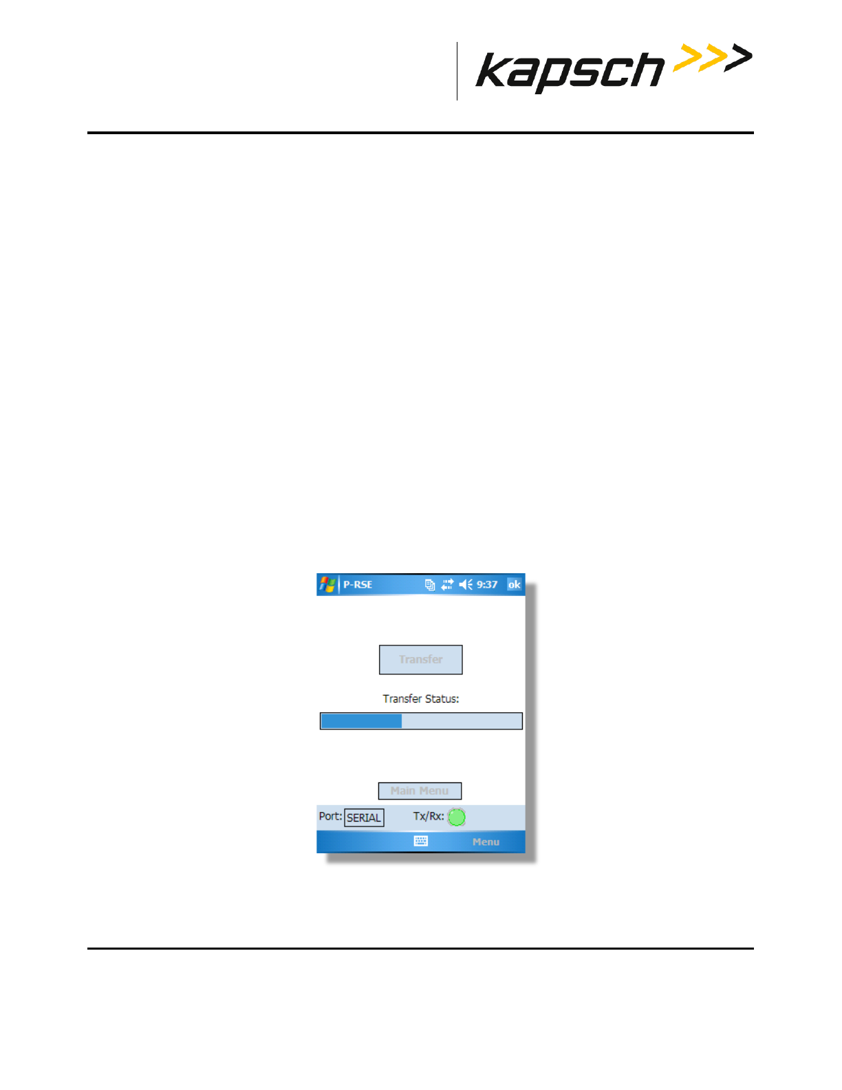
1. From the main menu, tap LC transfer. The Transfer screen appears.
NOTE: The OBU records are automatically deleted after they have been
successfully transferred to the LC.
2. From the Transfer screen, tap Transfer to immediately begin transferring the stored OBU records to the LC. A blue
Transfer Status bar indicates the progress of the transfer.
Figure 3-8: Data transfer in progress
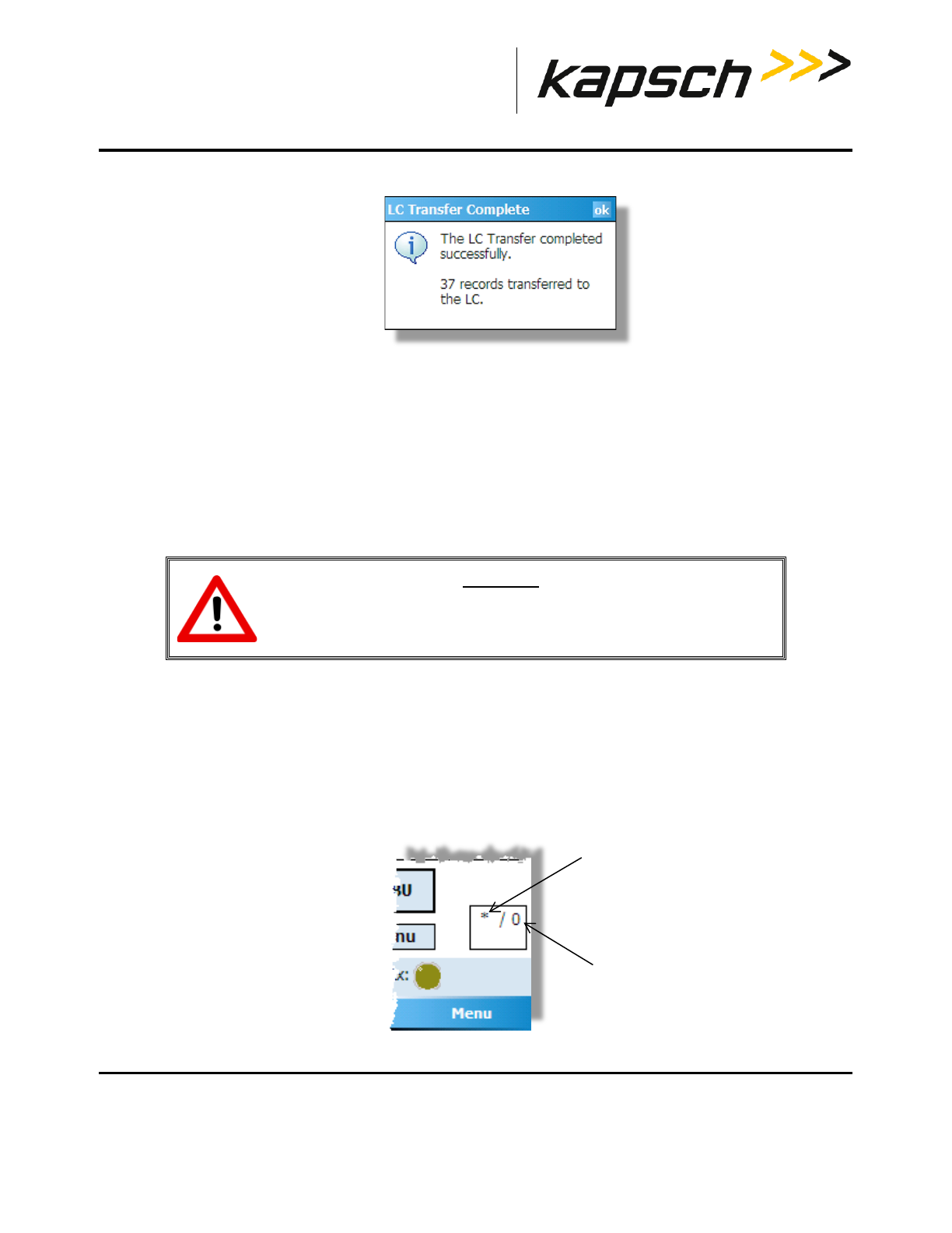
3. After the records have been successful transfer, a confirmation message appears:
Portable RSE
DOC#: UM 360453-700 REVISION: C Page 38 of 65
© Kapsch TrafficCom Canada Inc. 2013
These drawings and specifications contain confidential and proprietary information and are the property of Kapsch TrafficCom Canada Inc. and are issued in strict confidence
and will be kept confidential and used solely for the purpose intended and for no other purpose and shall not be transmitted, reproduced, copied, and/or used as the basis for
manufacture or sale of apparatus unless otherwise agreed to in writing by Kapsch TrafficCom Canada Inc.
FILE: P-RSE USER MANUAL - UM360453-700 REV_C.DOCX 08/19/2016 1:44
Kapsch TrafficCom
Figure 3-9: LC Transfer complete confirmation
4. If any error messages appear, resolve the errors as outlined in LC Transfer Error messages, page 56.
Erasing OBU data
OBU data is automatically erased from the Portable RSE after it has been transferred to the LC. However, you can
delete OBU data without transferring it to the LC. The only option available is to delete all OBU data; you cannot select
specific records to delete.
Prerequisites: None.
CAUTION:
Once the OBU data is erased, it cannot be recovered. To save the data,
transfer the OBU records to the LC.
1. From the Main menu, OBU Acquisition screen, Agency Screen, or Scratchpad Screen: Tap Menu in the bottom-
right of the screen tap Config. tap the OBU Data tab.
2. Read the warning message. Tap Erase OBU Data tap OK in the Erase OBU Data pop-up window to confirm
tap Yes in the second Erase OBU Data pop-up window to delete all OBU data.
3. When you return to the OBU Acquisition screen, the total number of OBU records will now be zero.
Figure 3-10: Zero OBU records
total number of OBU records = 0
no OBU record being displayed

Portable RSE
DOC#: UM 360453-700 REVISION: C Page 39 of 65
© Kapsch TrafficCom Canada Inc. 2013
These drawings and specifications contain confidential and proprietary information and are the property of Kapsch TrafficCom Canada Inc. and are issued in strict confidence and will be kept confidential and used solely for the purpose intended
and for no other purpose and shall not be transmitted, reproduced, copied, and/or used as the basis for manufacture or sale of apparatus unless otherwise agreed to in writing by Kapsch TrafficCom Canada Inc.
FILE: P-RSE USER MANUAL - UM360453-700 REV_C.DOCX 08/19/2016 1:44
Kapsch TrafficCom
Command and Controls
Command How is this command executed? What does this command do? What is the purpose of this command?
Applications
Manager
Press the Applications Manager button. displays the Applications Manager
screen, which displays a list of the
programs that are currently running
on the device.
not used within the Portable RSE
software
Context
Press the Context button. displays context information (ex.
Help screens) depending on the
current screen being displayed.
not used within the Portable RSE
software.
Enter
Press the Enter button. functions as a normal Enter key. not used within the Portable RSE
software
Home
Press the Home button. displays the Windows Mobile 5.0
Today screen.
not used within the Portable RSE
software

Portable RSE
DOC#: UM 360453-700 REVISION: C Page 40 of 65
© Kapsch TrafficCom Canada Inc. 2013
These drawings and specifications contain confidential and proprietary information and are the property of Kapsch TrafficCom Canada Inc. and are issued in strict confidence and will be kept confidential and used solely for the purpose intended
and for no other purpose and shall not be transmitted, reproduced, copied, and/or used as the basis for manufacture or sale of apparatus unless otherwise agreed to in writing by Kapsch TrafficCom Canada Inc.
FILE: P-RSE USER MANUAL - UM360453-700 REV_C.DOCX 08/19/2016 1:44
Kapsch TrafficCom
Command How is this command executed? What does this command do? What is the purpose of this command?
Power
Press the Power button. if pressed momentarily, suspends
Portable RSE into Hibernate mode.
if pressed and held for approx. 1
second, displays Power Button
menu.
If pressed and held for approx. 6
seconds, reboots the Portable RSE.
allows the user to Suspend, Reboot
(Reset), or Power Off the Portable RSE.
Start
Press the Start button. displays the Start menu to access the Settings necessary to set
the time and calibrate the touchscreen
Navigation
Press the Navigation button up, down, left, or
right.
moves the cursors and scrolls
through OBU records.
to scroll through the stored OBU
records from the OBU Acquisition
screen by pressing left or right.
About From any screen (except the Config or Diagnostics
screen),
tap Menu, then,
tap About.
displays the Portable RSE firmware
and software versions.
to confirm the firmware and software
of the Portable RSE are up to date.

Portable RSE
DOC#: UM 360453-700 REVISION: C Page 41 of 65
© Kapsch TrafficCom Canada Inc. 2013
These drawings and specifications contain confidential and proprietary information and are the property of Kapsch TrafficCom Canada Inc. and are issued in strict confidence and will be kept confidential and used solely for the purpose intended
and for no other purpose and shall not be transmitted, reproduced, copied, and/or used as the basis for manufacture or sale of apparatus unless otherwise agreed to in writing by Kapsch TrafficCom Canada Inc.
FILE: P-RSE USER MANUAL - UM360453-700 REV_C.DOCX 08/19/2016 1:44
Kapsch TrafficCom
Command How is this command executed? What does this command do? What is the purpose of this command?
Agency From the OBU Acquisition screen,
tap OBU Data in the bottom-left corner, then,
tap Agency.
displays the OBU Agency data. to view the Agency data of the OBU
data currently being viewed.
Antenna Navigate to the Configuration screen:
tap Menu in the bottom-right corner, then,
tap Config.
From the Configuration screen, tap the Config tab,
if necessary, then
select the appropriate Antenna from the drop-
down box, then,
tap OK.
identifies which antenna is
connected to the Portable RSE
(either short range or long range).
to configure the antenna.
Battery Power
(hibernate)
Navigate to the Configuration screen:
tap Menu in the bottom-right corner, then,
tap Config.
From the Configuration screen, tap the Hibernate
tab, if necessary, then
select the On Battery Power check box and select
a duration from the drop-down box, then,
tap OK.
enables automatic hibernation
when the Portable RSE is running on
battery power.
to enable the device to automatically
enter Hibernate mode when running
on battery power.
to select the duration of inactivity
before the Portable RSE enters sleep
mode.

Portable RSE
DOC#: UM 360453-700 REVISION: C Page 42 of 65
© Kapsch TrafficCom Canada Inc. 2013
These drawings and specifications contain confidential and proprietary information and are the property of Kapsch TrafficCom Canada Inc. and are issued in strict confidence and will be kept confidential and used solely for the purpose intended
and for no other purpose and shall not be transmitted, reproduced, copied, and/or used as the basis for manufacture or sale of apparatus unless otherwise agreed to in writing by Kapsch TrafficCom Canada Inc.
FILE: P-RSE USER MANUAL - UM360453-700 REV_C.DOCX 08/19/2016 1:44
Kapsch TrafficCom
Command How is this command executed? What does this command do? What is the purpose of this command?
Erase OBU Data Navigate to the Configuration screen:
tap Menu in the bottom-right corner, then,
tap Config.
From the Configuration screen, tap the OBU Data
tab, if necessary, then,
tap the Erase OBU Data button, then,
tap OK, then tap Yes to confirm.
deletes all OBU data stored on the
Portable RSE.
to clear the OBU data without
downloading it to the LC.
External Power
(hibernate)
Navigate to the Configuration screen:
tap Menu in the bottom-right corner, then,
tap Config.
From the Configuration screen, tap the Hibernate
tab, if necessary, then,
select the On External Power check box and select
a duration from the drop-down box, then,
tap OK.
enables automatic hibernation
when the Portable RSE is running on
AC power.
to enable the device to automatically
enter Hibernate mode when running
on AC power.
to select the duration of inactivity
before the Portable RSE enters sleep
mode.
LC Transfer From the Main Menu screen:
tap LC Transfer.
displays the LC transfer screen. to navigate to the LC transfer screen,
where OBU data can be transferred to
an LC.

Portable RSE
DOC#: UM 360453-700 REVISION: C Page 43 of 65
© Kapsch TrafficCom Canada Inc. 2013
These drawings and specifications contain confidential and proprietary information and are the property of Kapsch TrafficCom Canada Inc. and are issued in strict confidence and will be kept confidential and used solely for the purpose intended
and for no other purpose and shall not be transmitted, reproduced, copied, and/or used as the basis for manufacture or sale of apparatus unless otherwise agreed to in writing by Kapsch TrafficCom Canada Inc.
FILE: P-RSE USER MANUAL - UM360453-700 REV_C.DOCX 08/19/2016 1:44
Kapsch TrafficCom
Command How is this command executed? What does this command do? What is the purpose of this command?
Menu From any screen (except the Configuration,
Diagnostic or About screen),
tap Menu in the bottom-right corner.
displays a menu to select Config,
Diagnostics, or About.
to allow the user to select the Config,
Diagnostics, or About navigation
buttons.
Perform Health
Check
Navigate to the Diagnostics screen:
tap Menu in the bottom-right corner, then,
tap Diagnostics.
From the Diagnostics screen, tap Perform Health
Check.
performs a diagnostic check of the
Portable RSE.
to confirm that the Reader module is
functioning properly and is
communicating with the Field PC.
Previous From the Agency or Scratchpad screen,
tap Previous
displays the OBU Acquisition
screen.
to return to the OBU Acquisition screen
after viewing Agency or Scratchpad
data.
Read OBU
(navigation)
From the Main Menu screen:
tap Read OBU.
displays the OBU Acquisition
screen.
to navigate to the OBU Acquisition
screen, where OBU data can be viewed
and OBUs can be read.
Read OBU
(read)
From the OBU Acquisition screen,
tap Read OBU.
initiates an OBU Read attempt. to read OBU data.
Reporting Port this parameter is permanently set to Serial. identifies which port is used for
downloading data to the LC.
to configure communications to the LC.

Portable RSE
DOC#: UM 360453-700 REVISION: C Page 44 of 65
© Kapsch TrafficCom Canada Inc. 2013
These drawings and specifications contain confidential and proprietary information and are the property of Kapsch TrafficCom Canada Inc. and are issued in strict confidence and will be kept confidential and used solely for the purpose intended
and for no other purpose and shall not be transmitted, reproduced, copied, and/or used as the basis for manufacture or sale of apparatus unless otherwise agreed to in writing by Kapsch TrafficCom Canada Inc.
FILE: P-RSE USER MANUAL - UM360453-700 REV_C.DOCX 08/19/2016 1:44
Kapsch TrafficCom
Command How is this command executed? What does this command do? What is the purpose of this command?
RF Power Level Navigate to the Configuration screen:
tap Menu in the bottom-right corner, then,
tap Config.
From the Configuration screen, tap the Config tab,
if necessary, then,
select the appropriate RF Power Level from the
drop-down box, then,
tap OK.
sets the RF level used for
communicating with the OBU when
using the short range antenna.
to allow the user to configure an
optimal power level used for
communicating with the OBU with the
short-range antenna.
Scratchpad From the OBU Acquisition screen,
tap OBU Data in the bottom-left corner, then,
tap Scratchpad.
displays the OBU Scratchpad data. to view the Scratchpad data of the OBU
currently being viewed.
Transfer From the LC Transfer screen,
tap Transfer
Initiates a download of OBU data to
the LC.
to download the OBU data stored on
the Portable RSE to the LC.

Portable RSE
DOC#: UM 360453-700 REVISION: C Page 45 of 65
© Kapsch TrafficCom Canada Inc. 2013
These drawings and specifications contain confidential and proprietary information and are the property of Kapsch TrafficCom Canada Inc. and are issued in strict confidence
and will be kept confidential and used solely for the purpose intended and for no other purpose and shall not be transmitted, reproduced, copied, and/or used as the basis for
manufacture or sale of apparatus unless otherwise agreed to in writing by Kapsch TrafficCom Canada Inc.
FILE: P-RSE USER MANUAL - UM360453-700 REV_C.DOCX 08/19/2016 1:44
Kapsch TrafficCom
MAINTENANCE INSTRUCTIONS
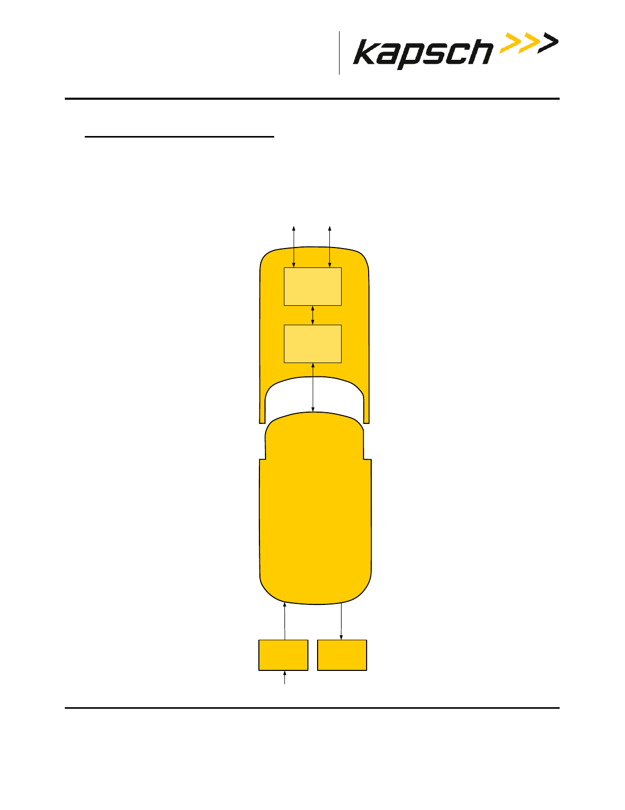
Portable RSE
DOC#: UM 360453-700 REVISION: C Page 46 of 65
© Kapsch TrafficCom Canada Inc. 2013
These drawings and specifications contain confidential and proprietary information and are the property of Kapsch TrafficCom Canada Inc. and are issued in strict confidence
and will be kept confidential and used solely for the purpose intended and for no other purpose and shall not be transmitted, reproduced, copied, and/or used as the basis for
manufacture or sale of apparatus unless otherwise agreed to in writing by Kapsch TrafficCom Canada Inc.
FILE: P-RSE USER MANUAL - UM360453-700 REV_C.DOCX 08/19/2016 1:44
Kapsch TrafficCom
4. THEORY OF OPERATIONS
This section offers a more detailed overview of the RSE components than the introductory overview provided in
Overview, Section 2, page 10. A functional block diagram of the Portable RSE is shown in Figure 4-1.
Figure 4-1: Functional Block Diagram
Reader
Module
Ultra-Rugged
Field PC
RF Circuitry
Microprocessor
RS-232
Short-range
Antenna
Long-range
Antenna
Power supply
12 VDC
120 VAC
Lane Controller
RS-232
or
USB 2.0

Portable RSE
DOC#: UM 360453-700 REVISION: C Page 47 of 65
© Kapsch TrafficCom Canada Inc. 2013
These drawings and specifications contain confidential and proprietary information and are the property of Kapsch TrafficCom Canada Inc. and are issued in strict confidence
and will be kept confidential and used solely for the purpose intended and for no other purpose and shall not be transmitted, reproduced, copied, and/or used as the basis for
manufacture or sale of apparatus unless otherwise agreed to in writing by Kapsch TrafficCom Canada Inc.
FILE: P-RSE USER MANUAL - UM360453-700 REV_C.DOCX 08/19/2016 1:44
Kapsch TrafficCom
RF Power Level settings
The RF signal level can be adjusted when the Portable RSE is configured to use the short-range antenna port. The RF
Power level is fixed at High when the Portable RSE is configured to use the long range antenna port since the purpose
of the long-range antenna port is to use the remote antenna with the Portable RSE. The RF Power Level settings
available are outlined in Table 4-1. The Medium and Low power settings are recommended for use in confined spaces
or when other OBUs are nearby.
Table 4-1: RF power level settings
RF Power Level Function
Low lowest RF signal level used to read OBUs
Medium medium RF signal level used to read OBUs
High highest RF signal level used to read OBUs
Auto attempts to read an OBU at the lowest RF signal
level, then increases the RF signal level until an
OBU is successfully Read, or the Portable RSE
has reached the maximum RF signal level.
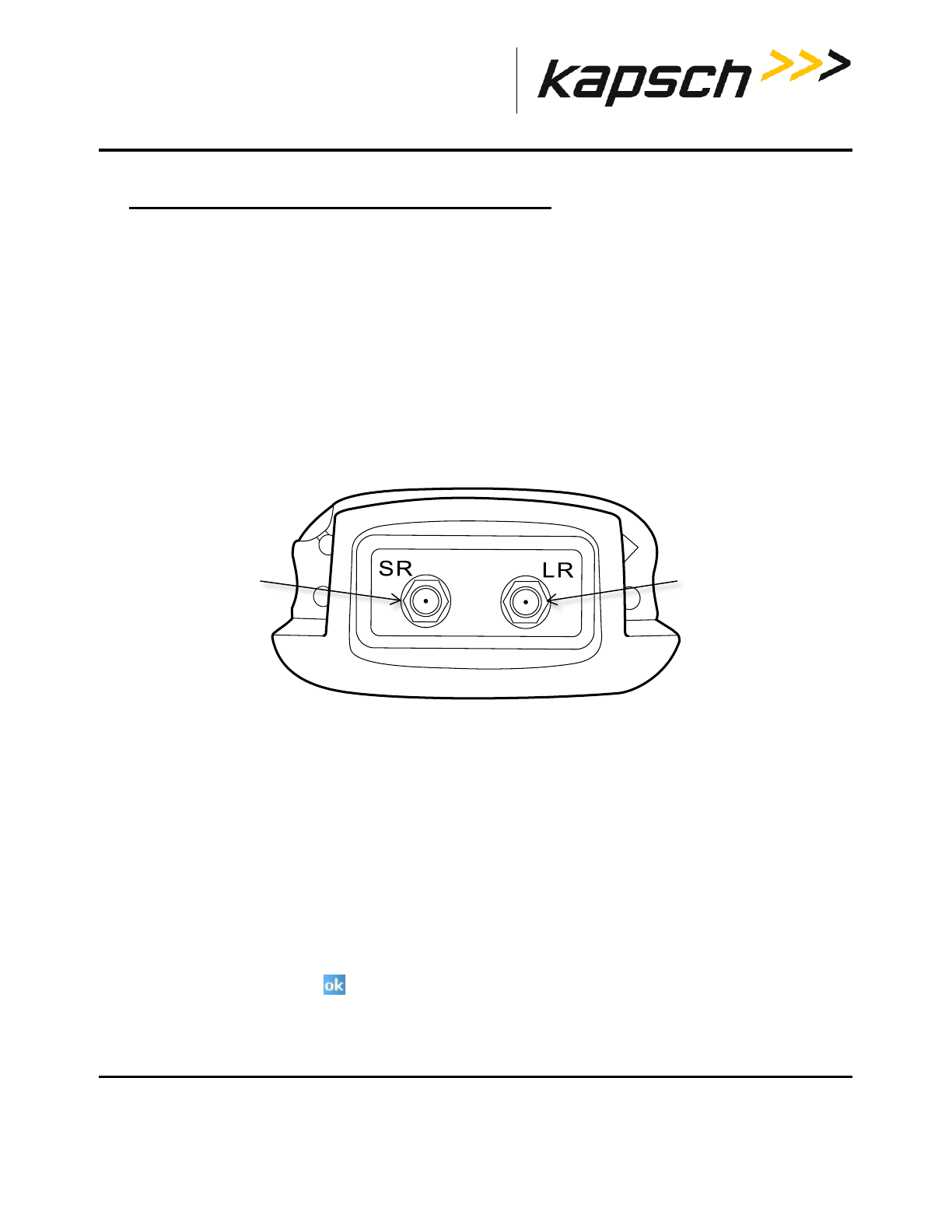
Portable RSE
DOC#: UM 360453-700 REVISION: C Page 48 of 65
© Kapsch TrafficCom Canada Inc. 2013
These drawings and specifications contain confidential and proprietary information and are the property of Kapsch TrafficCom Canada Inc. and are issued in strict confidence
and will be kept confidential and used solely for the purpose intended and for no other purpose and shall not be transmitted, reproduced, copied, and/or used as the basis for
manufacture or sale of apparatus unless otherwise agreed to in writing by Kapsch TrafficCom Canada Inc.
FILE: P-RSE USER MANUAL - UM360453-700 REV_C.DOCX 08/19/2016 1:44
Kapsch TrafficCom
5. INSTALLATION AND CONFIGURATION
Installing an antenna
There are two types of antennas available; a short-range antenna that can read OBUs from approx. 5 ft., or an
optional remote antenna that can read OBUs from approx. 9 ft. After the antenna is installed, the Portable RSE must
be configured to identify which antenna is being used.
1. Connect the antenna to the Portable RSE.
• If installing the short-range antenna, connect the antenna to the SR terminal at the top of the Portable RSE.
• If installing the remote antenna, connect the antenna to the LR terminal at the top of the Portable RSE.
Figure 5-1: Portable RSE antenna terminals (top view)
2. Connect the 50 Ω RF terminator to the unused antenna terminal.
3. Configure the Portable RSE antenna settings:
a) Navigate to the Configuration screen by tapping Menu in the bottom-right corner, tapping Config., then
tapping the Config tab.
b) From the Antenna drop-down box, select SHORT_RANGE or LONG_RANGE, depending on which type of
antenna was installed in step 1.
NOTE: When the Portable RSE antenna is configured for LONG_RANGE, the RF
Power is automatically set to HIGH and cannot be changed to ensure the
maximum communication distance.
c) From the RF Power Level drop down box, select the appropriate RF Power level.
NOTE: Tapping in the upper-right corner will exit the Config screen without
making changes.
d) Tap OK in the bottom-right corner to make changes and exit the Config screen.
long-range
antenna
terminal
short-range
antenna
terminal
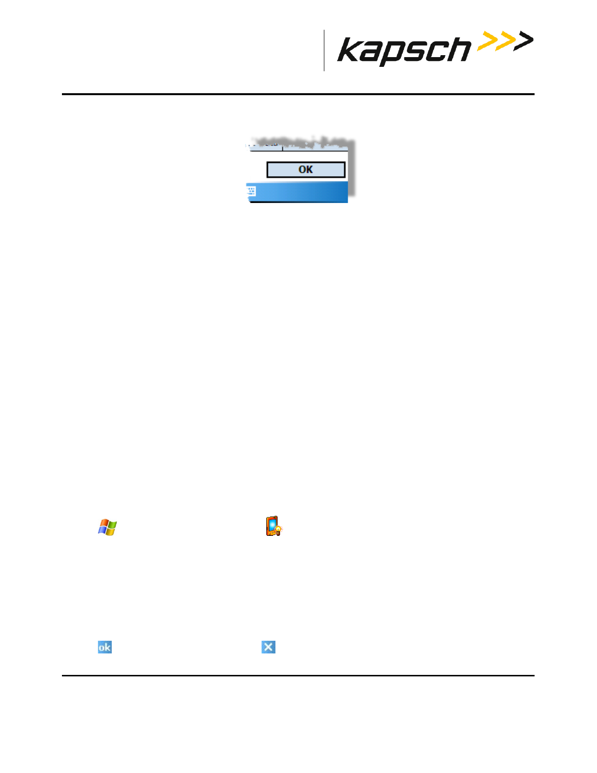
Portable RSE
DOC#: UM 360453-700 REVISION: C Page 49 of 65
© Kapsch TrafficCom Canada Inc. 2013
These drawings and specifications contain confidential and proprietary information and are the property of Kapsch TrafficCom Canada Inc. and are issued in strict confidence
and will be kept confidential and used solely for the purpose intended and for no other purpose and shall not be transmitted, reproduced, copied, and/or used as the basis for
manufacture or sale of apparatus unless otherwise agreed to in writing by Kapsch TrafficCom Canada Inc.
FILE: P-RSE USER MANUAL - UM360453-700 REV_C.DOCX 08/19/2016 1:44
Kapsch TrafficCom
Figure 5-2: OK button for committing configuration changes
Configuring automatic suspending
You can configure the Portable RSE to suspend into Hibernate mode after a configurable duration. Configure
Hibernate mode through the Portable RSE software as outlined in this procedure.
Prerequisites: None.
1. Navigate to the Configuration screen by tapping Menu in the bottom-right corner, tapping Config, then tapping
the Hibernate tab.
2. To configure automatic Hibernate when the RSE is running on battery power, select the On Battery Power check
box, then select a duration (between 1 and 5 min.) from the drop-down menu. The duration selected is the time
the RSE is inactive while operating on battery power before going into Hibernate mode.
3. To configure automatic Hibernate when the RSE is running on AC power, select the On External Power check box
then select a duration (between 1 and 30 min.) from the drop-down menu. The duration selected is the time the
RSE is inactive while operating on external power before going into Hibernate mode.
Configuring automatic backlight and screen dimming
Windows Mobile can be configured to dim the screen to reduce battery consumption without entering Hibernate
mode.
Prerequisites: None.
1. Tap Settings System tabBacklight . The Backlight settings are displayed.
2. The backlight settings for running on battery power and external power are configured separately. Tap the
applicable along the bottom of the Backlight screen to configure the appropriate settings.
3. Select Turn off backlight if device is not used for to enable backlight and screen dimming. Select a duration, from
10 sec. to 5 min., from the drop-down menu.
4. Select Turn on backlight when a button is pressed or the screen is tapped. If this option is not selected, the only
way to return the screen to normal brightness is to suspend and then wake the Portable RSE.
5. Tap to exit the Backlight screen, then tap to return to the Portable RSE software.
Portable RSE
DOC#: UM 360453-700 REVISION: C Page 50 of 65
© Kapsch TrafficCom Canada Inc. 2013
These drawings and specifications contain confidential and proprietary information and are the property of Kapsch TrafficCom Canada Inc. and are issued in strict confidence
and will be kept confidential and used solely for the purpose intended and for no other purpose and shall not be transmitted, reproduced, copied, and/or used as the basis for
manufacture or sale of apparatus unless otherwise agreed to in writing by Kapsch TrafficCom Canada Inc.
FILE: P-RSE USER MANUAL - UM360453-700 REV_C.DOCX 08/19/2016 1:44
Kapsch TrafficCom
Setting the time and date
When the Portable RSE reads an OBU, the system time and date is used to record the read time. This procedure
outlines how to set the system time and date.
Prerequisites: None.
1. Tap Settings System tabClock and Alarms Time tab.
2. Change the Home time as required. Tap to highlight the hour, minute, seconds, day, month or year then tap on
the arrow buttons to make changes.
3. Tap in the upper-right corner of the screen. Click Yes to save changes.

Portable RSE
DOC#: UM 360453-700 REVISION: C Page 51 of 65
© Kapsch TrafficCom Canada Inc. 2013
These drawings and specifications contain confidential and proprietary information and are the property of Kapsch TrafficCom Canada Inc. and are issued in strict confidence
and will be kept confidential and used solely for the purpose intended and for no other purpose and shall not be transmitted, reproduced, copied, and/or used as the basis for
manufacture or sale of apparatus unless otherwise agreed to in writing by Kapsch TrafficCom Canada Inc.
FILE: P-RSE USER MANUAL - UM360453-700 REV_C.DOCX 08/19/2016 1:44
Kapsch TrafficCom
6. TROUBLESHOOTING
Troubleshooting Methodology
When troubleshooting Portable RSE issues, first connect the Portable RSE to external power to ensure the Portable
RSE problems are not being caused by a defective battery. Then perform a Health Check (see Performing a Health
Check on the Diagnostics screen, page 51). Troubleshooting trees are provided for the most common Portable RSE
errors.
Returning the Portable RSE for service
If the Portable RSE requires service please contact Kapsch TrafficCom for an RMA number. Do not attempt to service
the device yourself.
Performing a Health Check on the Diagnostics screen
Performing a Health Check examines the main internal components of the Portable RSE: the Application-Specific
Integrated Circuit (ASIC), the Microprocessor Unit (MCU), and the communications between the Ultra-Rugged Field PC
and the Reader module. Performing the Health Check produces one of the following results:
Table 6-1: Health Check Status Results
To perform a Health Check:
1. From any screen (except the Config or About screen), tap Menu in the bottom-right corner, then, tap Diagnostics.
The Diagnostics screen appears.
Health Check Status Definition
OKAY The Portable RSE successfully passed all tests.
ASIC ERROR The ASIC is not functioning properly. Return the device for repairs.
MCU ERROR The MCU is not functioning properly. Return the device for repairs.
HW ERROR not currently used
COMMS ERROR The communications interface between the Ultra-Rugged Field PC
and the Reader Module is not functioning properly. Return the
device for repairs.
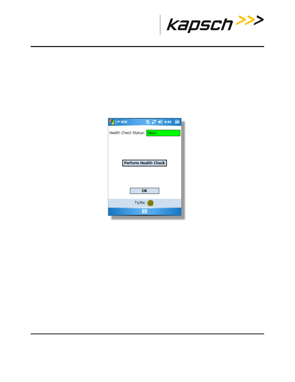
Portable RSE
DOC#: UM 360453-700 REVISION: C Page 52 of 65
© Kapsch TrafficCom Canada Inc. 2013
These drawings and specifications contain confidential and proprietary information and are the property of Kapsch TrafficCom Canada Inc. and are issued in strict confidence
and will be kept confidential and used solely for the purpose intended and for no other purpose and shall not be transmitted, reproduced, copied, and/or used as the basis for
manufacture or sale of apparatus unless otherwise agreed to in writing by Kapsch TrafficCom Canada Inc.
FILE: P-RSE USER MANUAL - UM360453-700 REV_C.DOCX 08/19/2016 1:44
Kapsch TrafficCom
NOTE: The Health Check Status shown when the Diagnostics screen appears is the
result from the previous Health Check.
2. To perform a new Health Check, tap Perform Health Check.
3. After a short delay while the tests are being performed, the Health Check Status is displayed (see Table 6-1:
Health Check Status Results). If any errors appear, return the Portable RSE for repairs.
4. Tap Ok to exit the Diagnostics screen.
Figure 6-1: The Diagnostics Screen
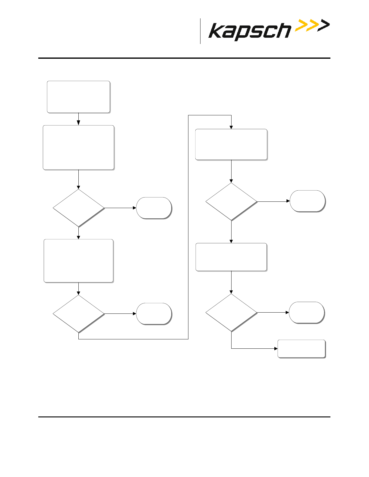
Portable RSE
DOC#: UM 360453-700 REVISION: C Page 53 of 65
© Kapsch TrafficCom Canada Inc. 2013
These drawings and specifications contain confidential and proprietary information and are the property of Kapsch TrafficCom Canada Inc. and are issued in strict confidence
and will be kept confidential and used solely for the purpose intended and for no other purpose and shall not be transmitted, reproduced, copied, and/or used as the basis for
manufacture or sale of apparatus unless otherwise agreed to in writing by Kapsch TrafficCom Canada Inc.
FILE: P-RSE USER MANUAL - UM360453-700 REV_C.DOCX 08/19/2016 1:44
Kapsch TrafficCom
Troubleshooting tree: Difficulty reading OBUs consistently
START
Symptom:
P-RSE has difficulty
reading OBUs.
Contact Kapsch
Service Assistance
Ensure that the P-RSE is
configured for the antenna
currently installed
and that the antenna is
oriented properly.
P-RSE is
functional
No
P-RSE
consistently reads
OBUs?
If using a short range
antenna, ensure that the RF
Power Level is appropriate for
the distance between the
reader and the transponder.
Yes
Check that the P-RSE is
orientated correctly when
reading an OBU .
P-RSE is
functional
P-RSE is
functional
No
Yes
No
Yes
Attempt to read a
known good OBU.
P-RSE is
functional
No
Yes
P-RSE
consistently reads
OBUs?
P-RSE
consistently reads
OBUs?
P-RSE
consistently reads
OBU?
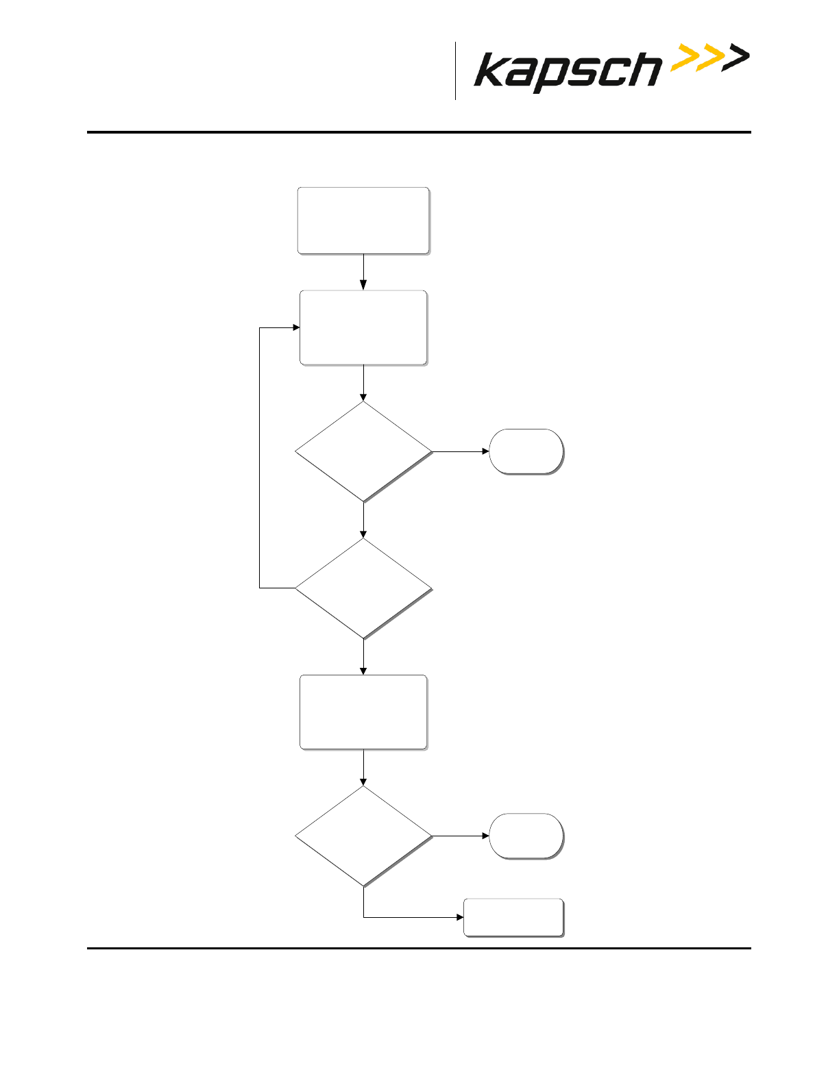
Portable RSE
DOC#: UM 360453-700 REVISION: C Page 54 of 65
© Kapsch TrafficCom Canada Inc. 2013
These drawings and specifications contain confidential and proprietary information and are the property of Kapsch TrafficCom Canada Inc. and are issued in strict confidence
and will be kept confidential and used solely for the purpose intended and for no other purpose and shall not be transmitted, reproduced, copied, and/or used as the basis for
manufacture or sale of apparatus unless otherwise agreed to in writing by Kapsch TrafficCom Canada Inc.
FILE: P-RSE USER MANUAL - UM360453-700 REV_C.DOCX 08/19/2016 1:44
Kapsch TrafficCom
Troubleshooting tree: Battery does not fully charge to 100% (0 mAH consumed)
START
Symptom:
Battery does not fully
charge to 100% capacity.
Contact Kapsch
Service Assistance
Completely discharge the
battery, then try to
recharge the battery to
100% capacity.
Yes
No
Battery is
functional
No
Yes
Has the battery
been fully discharged,
then recharged
3 times?
Battery charges to
100% capacity?
Replace the battery,
then try to recharge the
battery to 100% capacity.
Battery charges to
100% capacity?
Battery is
functional
Yes
Yes
No
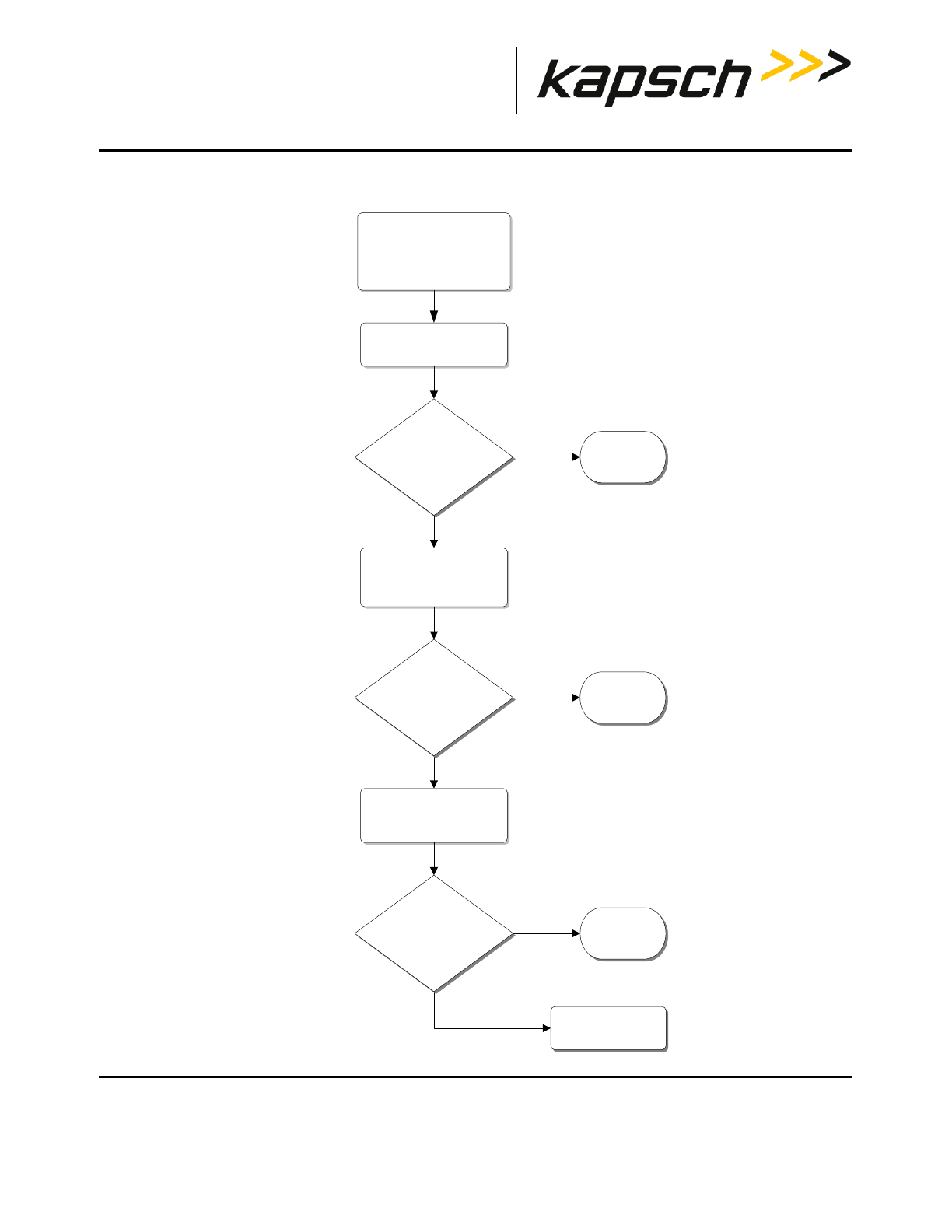
Portable RSE
DOC#: UM 360453-700 REVISION: C Page 55 of 65
© Kapsch TrafficCom Canada Inc. 2013
These drawings and specifications contain confidential and proprietary information and are the property of Kapsch TrafficCom Canada Inc. and are issued in strict confidence
and will be kept confidential and used solely for the purpose intended and for no other purpose and shall not be transmitted, reproduced, copied, and/or used as the basis for
manufacture or sale of apparatus unless otherwise agreed to in writing by Kapsch TrafficCom Canada Inc.
FILE: P-RSE USER MANUAL - UM360453-700 REV_C.DOCX 08/19/2016 1:44
Kapsch TrafficCom
Troubleshooting tree: Touchscreen responds inaccurately to inputs
START
Symptom:
Touch screen responds
inaccurately to inputs
Contact Kapsch
Service Assistance
Ensure device is unlocked.
Recalibrate the touch
screen.
See page 62
Touch screen
is functional
No
Does touch screen
respond correctly to
inputs?
Yes
Touch screen
is functional
No
Does touch screen
respond correctly to
inputs?
Yes
Reset the P-RSE.
See page 25
Touch screen
is functional
No
Does touch screen
respond correctly to
inputs?
Yes
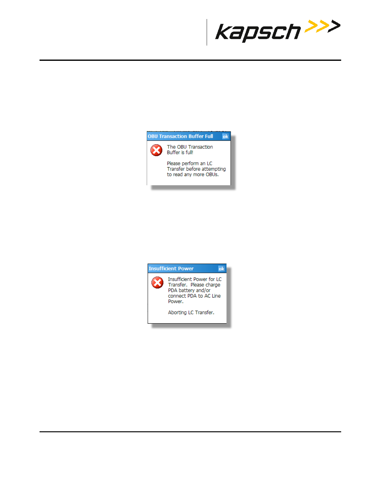
Portable RSE
DOC#: UM 360453-700 REVISION: C Page 56 of 65
© Kapsch TrafficCom Canada Inc. 2013
These drawings and specifications contain confidential and proprietary information and are the property of Kapsch TrafficCom Canada Inc. and are issued in strict confidence
and will be kept confidential and used solely for the purpose intended and for no other purpose and shall not be transmitted, reproduced, copied, and/or used as the basis for
manufacture or sale of apparatus unless otherwise agreed to in writing by Kapsch TrafficCom Canada Inc.
FILE: P-RSE USER MANUAL - UM360453-700 REV_C.DOCX 08/19/2016 1:44
Kapsch TrafficCom
LC Transfer Error messages
OBU Transaction Buffer Full.
The Portable RSE can store a maximum of 1000 OBU records in its transaction buffer. Once the transaction buffer limit
is reached, the message shown in Figure 6-2 appears. OBUs cannot be read until the transaction buffer is cleared.
Figure 6-2: OBU Transaction Buffer Full message
Solution: Download the OBU records to the lane controller (see Transferring Data to the LC, page 37), or, if absolutely
necessary, permanently erase all OBU records (see Erasing OBU data, page 38). 24
Insufficient Power (to transfer data to LC)
If battery power is low (approx. 10% or less), the error message in Figure 6-3 appears and OBU records cannot be
downloaded to the LC to prevent the data transfer from being interrupted.
Figure 6-3: Insufficient Power message
Solution: Connect the Portable RSE to the external power supply.
Portable RSE
DOC#: UM 360453-700 REVISION: C Page 57 of 65
© Kapsch TrafficCom Canada Inc. 2013
These drawings and specifications contain confidential and proprietary information and are the property of Kapsch TrafficCom Canada Inc. and are issued in strict confidence
and will be kept confidential and used solely for the purpose intended and for no other purpose and shall not be transmitted, reproduced, copied, and/or used as the basis for
manufacture or sale of apparatus unless otherwise agreed to in writing by Kapsch TrafficCom Canada Inc.
FILE: P-RSE USER MANUAL - UM360453-700 REV_C.DOCX 08/19/2016 1:44
Kapsch TrafficCom
7. MAINTENANCE PROCEDURES
Cleaning the Portable RSE touch screen
Keep the touch screen clean to ensure the touch screen responds accurately to touch inputs.
CAUTION:
Do not clean the touch screen using tissues, paper towels or harsh cleaning
agents as these can damage the device.
CAUTION:
Long exposure to the following solutions may damage the device:
• pine oil
• oil-based paint
• automotive brake cleaner
• isopropyl alcohol
•
carburetor cleaner
1. Suspend the Portable RSE (see Suspending the Portable RSE, page 23).
2. Remove the screen protector, if applicable.
3. Apply water or a mild cleaning solution to a microfiber cloth and gently wipe off the touchscreen.
4. Wake the Portable RSE (see Waking the Portable RSE, page 23).

Portable RSE
DOC#: UM 360453-700 REVISION: C Page 58 of 65
© Kapsch TrafficCom Canada Inc. 2013
These drawings and specifications contain confidential and proprietary information and are the property of Kapsch TrafficCom Canada Inc. and are issued in strict confidence
and will be kept confidential and used solely for the purpose intended and for no other purpose and shall not be transmitted, reproduced, copied, and/or used as the basis for
manufacture or sale of apparatus unless otherwise agreed to in writing by Kapsch TrafficCom Canada Inc.
FILE: P-RSE USER MANUAL - UM360453-700 REV_C.DOCX 08/19/2016 1:44
Kapsch TrafficCom
Protecting the touchscreen
Protect the touchscreen from impact, pressure or abrasive substances that could damage it. To further protect the
touchscreen, apply one of the adhesive screen protectors that come with your device.
Calibrating the touchscreen
Calibrate the touchscreen to ensure that touch inputs are interpreted accurately.
1. Tap Settings System tabScreen .
2. From the General tab, tap Align Screen. The Align Screen window appears.
3. In the center of the Align Screen are crosshairs. Firmly and accurately tap the center of the crosshairs with a
stylus. The crosshairs move to the upper-left corner of the Align Screen.
4. Continue firmly and accurately tapping the crosshairs as they move to the four corners of the Align Screen.
5. If calibration is successful, the General tab of the Screen settings appears after the upper-right crosshair is tapped
and calibration is complete.
6. If calibration fails, the crosshairs reappear in the center of Align Screen and the calibration procedure repeats.
Ensure you tap the center of the crosshairs firmly and accurately.
7. If calibration continues to fail:
• Ensure an object in not lodged under the touch screen bezel.
• Clean the touch screen with a microfiber cloth.
• Inspect the touch screen for wear or damage. Contact Kapsch Service Assistance if the Portable RSE is
damaged.

Portable RSE
DOC#: UM 360453-700 REVISION: C Page 59 of 65
© Kapsch TrafficCom Canada Inc. 2013
These drawings and specifications contain confidential and proprietary information and are the property of Kapsch TrafficCom Canada Inc. and are issued in strict confidence
and will be kept confidential and used solely for the purpose intended and for no other purpose and shall not be transmitted, reproduced, copied, and/or used as the basis for
manufacture or sale of apparatus unless otherwise agreed to in writing by Kapsch TrafficCom Canada Inc.
FILE: P-RSE USER MANUAL - UM360453-700 REV_C.DOCX 08/19/2016 1:44
Kapsch TrafficCom
Replacing the battery pack
Do not store or leave the device or battery pack near a heat source, or otherwise expose it to temperatures in excess
of 140oF (60oC).
Use only Battery Packs approved for this device.
Do not try to open the battery pack
Do not short the external contacts on the battery pack
Do not install the battery pack backwards so that polarity is reversed.
Do not solder directly onto the battery pack.
Do not place the battery pack in direct sunlight.
In the rare event that the battery pack leaks and fluid get into the eye, do not rub the eye, rinse well with water and
immediately seek medical care.
Determining the software and firmware versions
To determine the Portable RSE software version and RSE main unit firmware version currently running on the Portable
RSE:
1. From any screen (except the Config or Diagnostics screen), tap Menu in the bottom-right corner, then, tap About.
2. The About screen appears, displaying the current software and firmware versions.
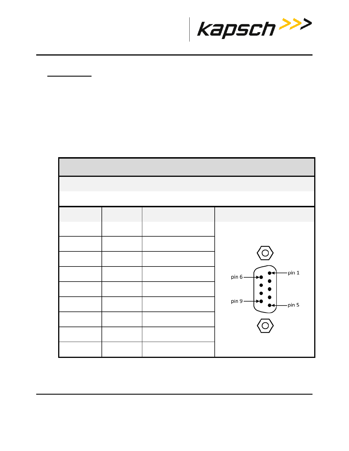
Portable RSE
DOC#: UM 360453-700 REVISION: C Page 60 of 65
© Kapsch TrafficCom Canada Inc. 2013
These drawings and specifications contain confidential and proprietary information and are the property of Kapsch TrafficCom Canada Inc. and are issued in strict confidence
and will be kept confidential and used solely for the purpose intended and for no other purpose and shall not be transmitted, reproduced, copied, and/or used as the basis for
manufacture or sale of apparatus unless otherwise agreed to in writing by Kapsch TrafficCom Canada Inc.
FILE: P-RSE USER MANUAL - UM360453-700 REV_C.DOCX 08/19/2016 1:44
Kapsch TrafficCom
8. APPENDIX
Technical Specifications and Pin outs
Tech specs:
The portable RSE is designed to operate over the temperature range of -22oF (-30oC) to 122oF (50oC). At
temperatures below 14oF (-10oC) the Liquid Crystal Display (LCD) may respond more slowly or the display
backlight may become dim to reduce the load on the battery power. To store the device in extreme temperatures
(lower then -22oF or higher then 140oF, the battery pack must be removed from the unit).
Serial port pin out
Connector Type
9-pin serial port, male
Pin Number Signal Description Diagram
1 DCD Data Carrier Detect input
2 RCD Receive Data input
3 TXD Transmit Data output
4 DTR Data Terminal Ready output
5 GND Ground
6 DSR Data Set Ready input
7 RTS Request to Send output
8 CTS Clear To Send input
9 RI Ring Indicator input

Portable RSE
DOC#: UM 360453-700 REVISION: C Page 61 of 65
© Kapsch TrafficCom Canada Inc. 2013
These drawings and specifications contain confidential and proprietary information and are the property of Kapsch TrafficCom Canada Inc. and are issued in strict confidence
and will be kept confidential and used solely for the purpose intended and for no other purpose and shall not be transmitted, reproduced, copied, and/or used as the basis for
manufacture or sale of apparatus unless otherwise agreed to in writing by Kapsch TrafficCom Canada Inc.
FILE: P-RSE USER MANUAL - UM360453-700 REV_C.DOCX 08/19/2016 1:44
Kapsch TrafficCom
Reference Documents
ICD 360430-101 Interface Control Document for the Next Generation RSE External Hardware
Interface.
ICD 360453-702 Portable RSE Reporting Interface Control Document
FSP-001 IAG Lane Tuning Procedure
322704-TAB Calibration Procedures
322710-078 Gold Transponder and Production Tester Calibration and Maintenance Procedure
Other commercial Documents:
14928-05 Field PC User Guide

Portable RSE
DOC#: UM 360453-700 REVISION: C Page 62 of 65
© Kapsch TrafficCom Canada Inc. 2013
These drawings and specifications contain confidential and proprietary information and are the property of Kapsch TrafficCom Canada Inc. and are issued in strict confidence
and will be kept confidential and used solely for the purpose intended and for no other purpose and shall not be transmitted, reproduced, copied, and/or used as the basis for
manufacture or sale of apparatus unless otherwise agreed to in writing by Kapsch TrafficCom Canada Inc.
FILE: P-RSE USER MANUAL - UM360453-700 REV_C.DOCX 08/19/2016 1:44
Kapsch TrafficCom
Acronyms and Synonyms
Term Meaning Reference, example, or explanation
Ant
Antenna
Antenna type displayed on OBU Acquisition
screen
ASIC
Application-Specific Integrated
Circuit
a circuit designed for a specific use
AU
Auto
Auto RF signal level enabled indication on OBU
Acquisition screen
CF
Compact Flash
Compact flash card that converts the Compact
Flash slot to an RS-232 port.
CRC
Cyclical Redundancy Check
GUI
Graphical User Interface
The human-machine interface that presents
information to the user and allows the user to
control the software by using windows, icons and
menus which can be manipulated by interacting
with the touch screen.
HI
high
High RF signal level enabled indication on OBU
Acquisition screen
HW
hardware
IAG
Inter-Agency Group
A group of toll highway agencies regulating
common tag content and use.
ICD
Interface Control Document
Specification of the protocol between two
components.
LC
Lane Controller
Controls readers and receives data and alerts
from RSEs.
LCD
Liquid Crystal Display
Thin flat display device, using multi-colored pixels
in front of a light source
LED
Light Emitting Diode
Used as status indicators on Janus RSE
LO
low
Low RF signal level enabled indication on OBU
Acquisition screen
LR
long-range
Long-range antenna port enabled indication on
OBU Acquisition screen
MCU
Microcontroller Unit
MD
medium
Medium RF signal level enabled indication on OBU
Acquisition screen

Portable RSE
DOC#: UM 360453-700 REVISION: C Page 63 of 65
© Kapsch TrafficCom Canada Inc. 2013
These drawings and specifications contain confidential and proprietary information and are the property of Kapsch TrafficCom Canada Inc. and are issued in strict confidence
and will be kept confidential and used solely for the purpose intended and for no other purpose and shall not be transmitted, reproduced, copied, and/or used as the basis for
manufacture or sale of apparatus unless otherwise agreed to in writing by Kapsch TrafficCom Canada Inc.
FILE: P-RSE USER MANUAL - UM360453-700 REV_C.DOCX 08/19/2016 1:44
Kapsch TrafficCom
Term Meaning Reference, example, or explanation
OBU
On Board Unit
Also referred to as a transponder or tag
Portable RSE
Portable Roadside Equipment
A hand-held device used to read On Board Units.
Pwr
Power
RF power level displayed on OBU Acquisition
screen
RSE
Roadside Equipment
A device used to read On Board Units.
RF
Radio Frequency
Broadcast band transmission frequencies
SR
short-range
Short-range antenna enabled indication on OBU
Acquisition screen