KCodes KCODES-601N KCodes 1-port Wireless USB Device Server User Manual UDS KCodes600s UM
KCodes Corporation KCodes 1-port Wireless USB Device Server UDS KCodes600s UM
UserManual.wiki
>
KCodes
>
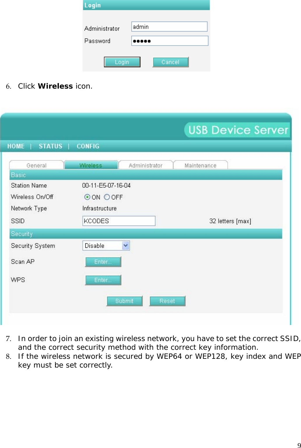
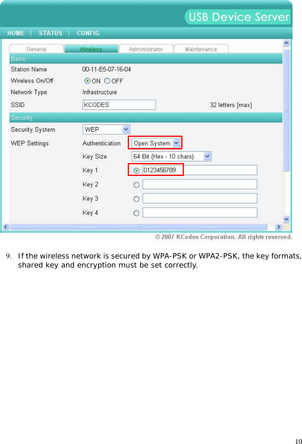
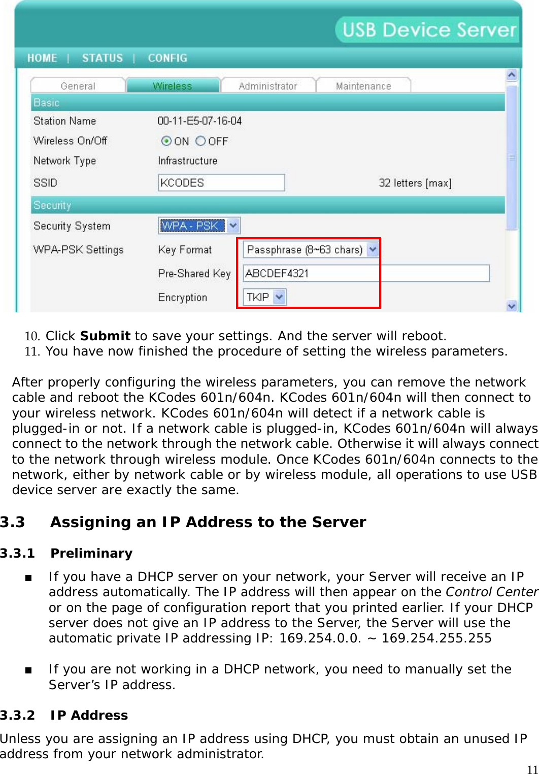
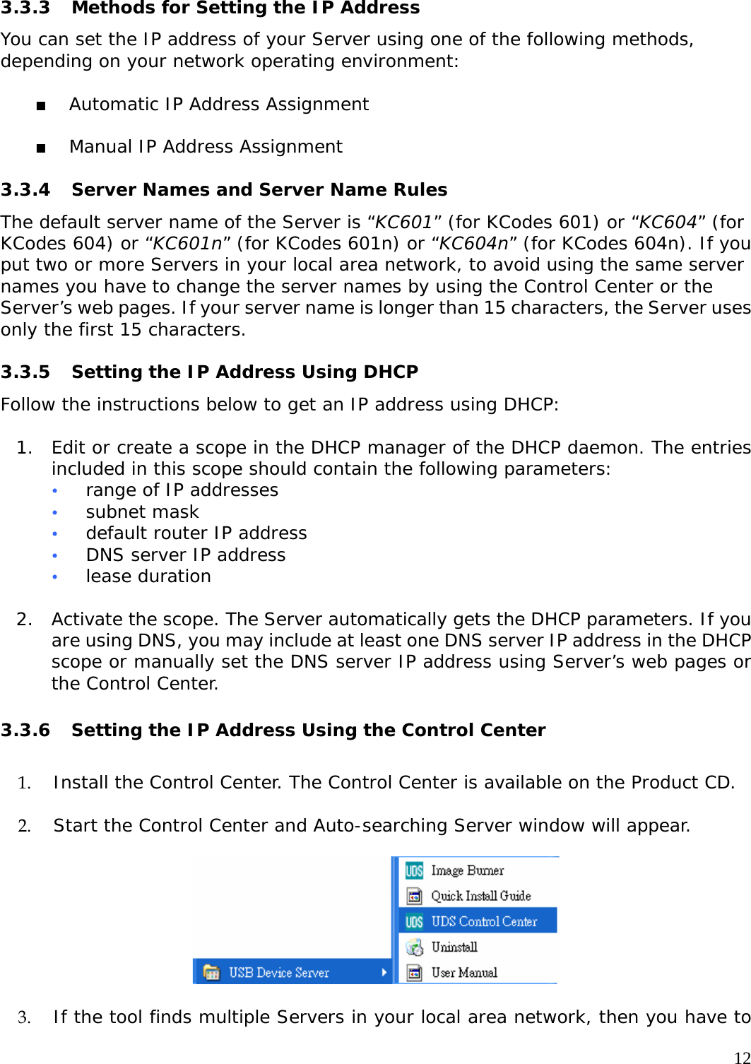
KCODES 601N User Manual
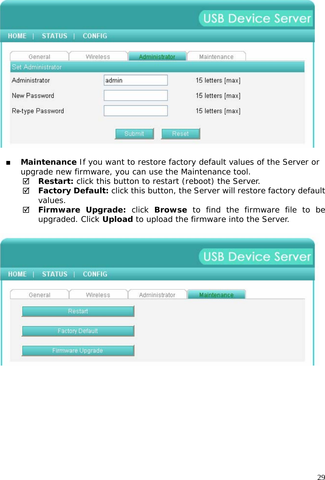
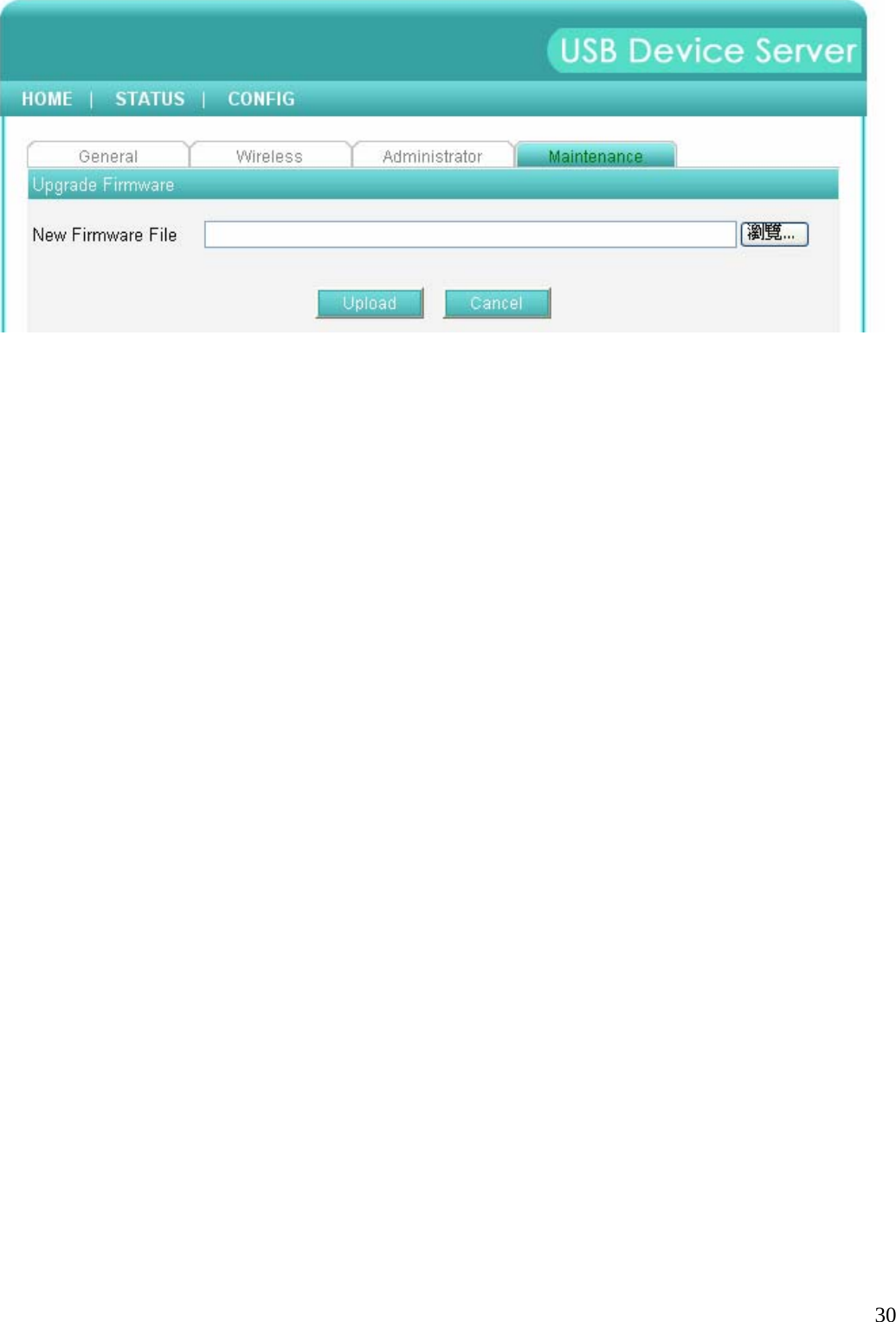
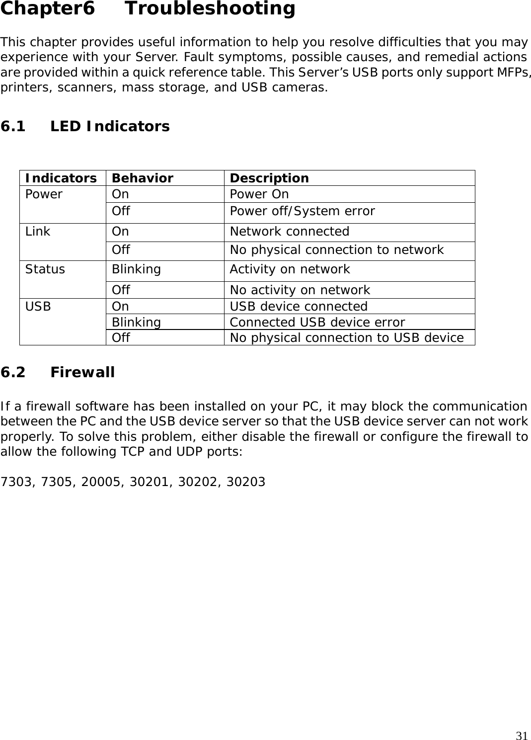
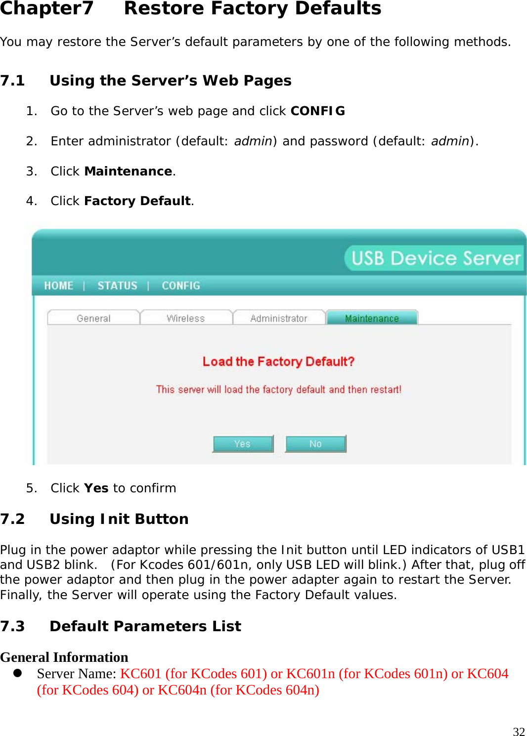
User Manual
Navigation menu
Upload a User Manual
Namespaces
Wiki Guide
HTML
PDF
Info
Views
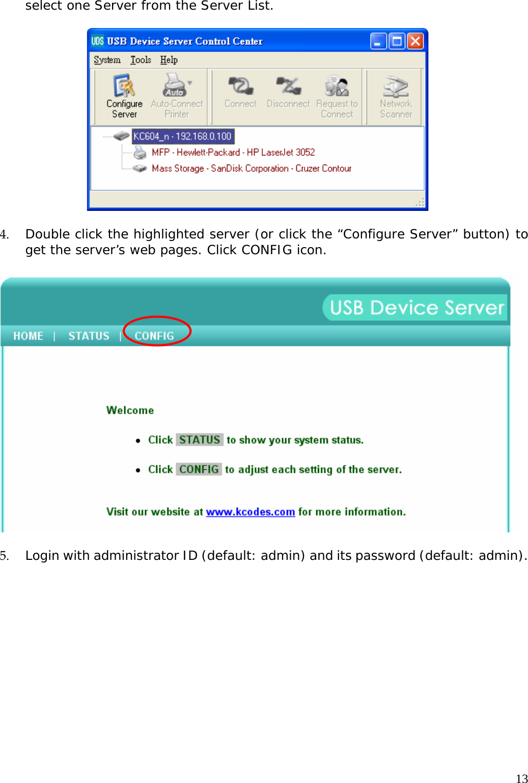
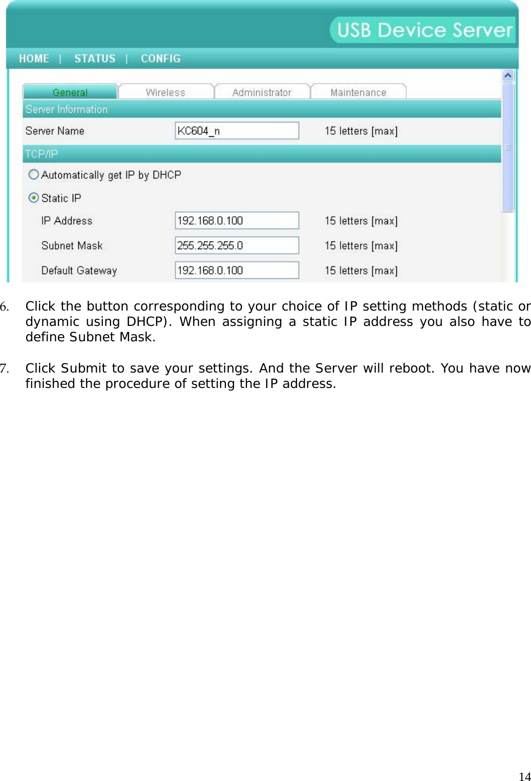
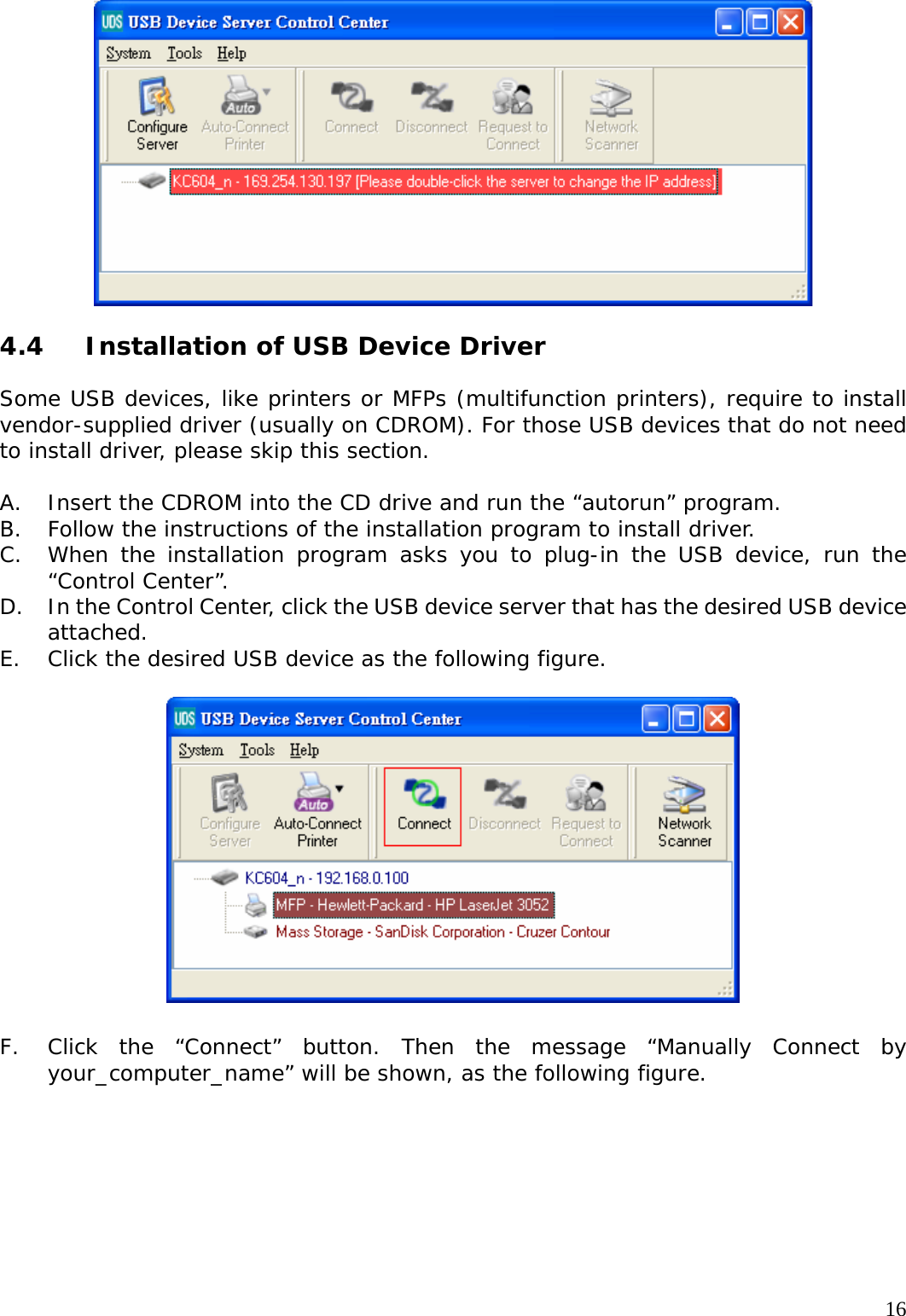
User Manual
Discussion / Help
Navigation