KCodes KCODES-604 KC604X printer server User Manual
KCodes Corporation KC604X printer server Users Manual
KCodes >
Users Manual
© 2014 KCodes Corporation. All rights reserved. 6 Series v2 User’s Manual V1.0
KCodes 6 Series v2 USB 2.0 Device Server
User’s Manual
Chapter 1 Introduction
Thak ou fo puhasig 6/6/64/64 U“B Deie “ee i the folloig efeed to as “ee.
This Server is designed to connect your Multifunction Printer, Scanner, Fax, Multifunction Printer, Hard Drive,
iPhone, iPod, USB Digital TV Tuner, Digital Camera, USB Webcam, USB Speaker, USB CD, USB DVD to your
etok, alloig all etok uses’ aess to these shaed U“B deies.
1.1 About 4 Models Described in this Manual
This manual provides introductory information as well as detailed instructions on how to set up and
manage 6 Series in various network environments. The following table shows the differences among the
4 models. All 4 models have a 10/100 Mbit/sec Lan port. However, 601 v2 and 601n v2 has only one USB
port, while both 604 v2 and 604n v2 have four USB ports. Compared with 4 models have an additional
wireless module (802.11b/g/n). Except for the wireless configuration, most configuration and operations
are the same for 601 v2/604 v2 and 601n v2/604n v2. Similarly, almost all of the configuration and
operations are the same for these models except that only one USB device can be connected to 601
v2/601n v2 while at most four USB devices can be connected to 604 v2/604n v2. Unless explicitly
specified, all instructions in the manual apply to 6 Series.
Model Nae
LAN
Wieless
U“B Pots
6
Yes
No
64
Yes
No
4
6
Yes
Yes
64
Yes
Yes
4
To fully benefit from this document, you should be familiar with basic networking principles. The
instructions described in this manual are based on the settings in a new Server. To reload the Factory
Parameters, you can reset this Server back to Factory Default, which will restore most of the settings. For
details, please efe to the hapte Restoe Fato Defaults.
1.2 Customer Support
Should you require any technical assistance, please contact your product reseller. Or you can visit our
website for latest product information. This document is subject to changes without prior notice.

© 2014 KCodes Corporation. All rights reserved. 6 Series v2 User’s Manual V1.0
Chapter 2 Product Overview
2.1 Package Contents
Verify that nothing is missing from the package by using the checking list below. Please contact your
dealer if anything is missing or damaged. All packing materials are recyclable. Please confirm the items in
the package below:
This Server ( 601/601n/604/604n)
CD (Control Center and User’s Manual and Quick Installation Guide)
Power Adaptor
2.2 Product CD
This CD provides easy-to-use Cotol Cete softae, ad the Use’s Maual ad Quik Istallatio
Guide.
2.2.1. Start-up Procedures
If your computer is configured to auto start CDs, this CD will start automatically when inserted. You can
also navigate to the CD and start the autorun.exe file from within the Windows file manager.
2.3 Physical Description
1. Power Adaptor Connector : 5V/1A (for 601 v2/601n v2) or 12V/2A (for 604 v2/604n v2)
2. Init Button : for restoring the configurable parameters to the default values
3. Wireless Station (only for 601n v2/604n v2) : IEEE 802.11 b/g/n wireless station with antenna
4. Ethernet Connector : connected to a twisted pair category 5 cable
5. USB Host Ports: USB 1.1/2.0 low, full, and Hi-Speed compliant
6. Indicators
For 6 Series
Power Indicator is lit while power is applied. If it is not lit, or if it blinks, there is a problem with the
USB device server or Power Adapter.
USB Indicator (one for 601 v2/601n v2, four for 604 v2/604n v2) is lit while a USB device connects
to a USB Port of the USB device server. If it is not lit, there is a problem with the USB device or the
USB device server.
For 601 v2/604 v2
Link Status is lit while network is applied. If it is not lit, it indicates that this server does not connect
to the network.
Status Indicator blinks to indicate network activity.

© 2014 KCodes Corporation. All rights reserved. 6 Series v2 User’s Manual V1.0
For 601n v2/604n v2
LAN Indicator blinks to indicate wired network activity. If it is lit, it indicates the wired network is
applied. If it is not lit, it indicates that the server does not connect to the wired network.
WLAN Indicator blinks to indicate wireless network activity. If it is lit, it indicates the wireless
network is applied. If it is not lit, it indicates that the server does not connect to the wireless
network.
2.4 Supported USB Devices
The USB device server supports the following types of USB devices.
USB Printer
USB multifunction printer (MFP/AIO)
USB scanner
USB storage
iPad
iPhone

© 2014 KCodes Corporation. All rights reserved. 6 Series v2 User’s Manual V1.0
Chapter 3 Basic Installation
3.1. Connecting the Hardware
1. Make sue that ou U“B deies ae sithed off ad that the “ee’s Poe Adapte is
disconnected.
2. Connect the USB devices to the USB ports with the USB cables.
3. Connect the Server to the network with a twisted-pair category 5 cable, 10baseT or 100baseTX.
4. Turn on the USB devices and make sure it is ready for use.
5. Connect the Power Adapter to the Server. The power indicator will light up and USB1 and USB2
indicators will flash in turn. (For 601/601n, only USB1 indicator will flash.) When the Link indicator
lights up, the Server is correctly connected to the network. When USB1 and USB2 indicators stop
flashing, the Server starts to work normally.
3.2. Wireless connection
This section only applies to 601n/604n.
3.3.1. Preliminary
Before you can access wireless network, wireless parameters should be set correctly. You
have to setup the first wireless parameter set through LAN (wired) connection.
Wireless access can be set as infrastructure (station) mode, which need an access point to
route network messages with the same SSID.
Wireless access can be secured by WEP (64/128), WPA-PSA (TKIP/AES), and WPA2-PSK (AES).
If parameters mismatch causes wireless access is not allowed, you have to modify those
parameters through LAN connection.
In infrastructure mode, the maximal transfer rate is 150 MBits depending on access point’s
capability.
3.3.2. Set Wireless Configuration Using Control Center
1. Install USB Device Server Control Center. It is available in the 601n v2/604n v2 USB Device Server
Product CD.
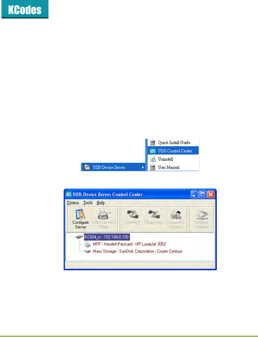
2. Start USB Device Server Control Center and Auto-searching USB device server window will appear.
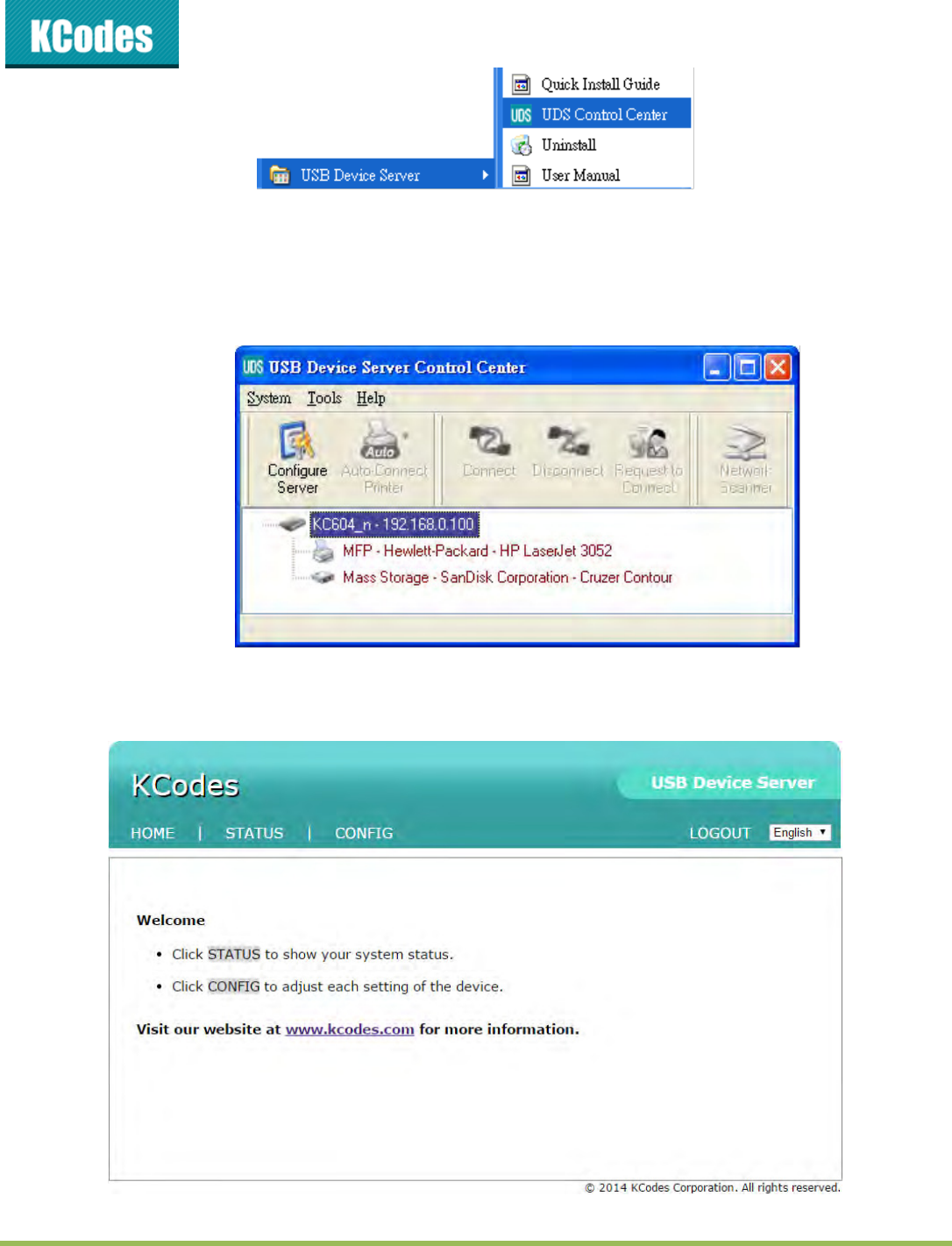
© 2014 KCodes Corporation. All rights reserved. 6 Series v2 User’s Manual V1.0
I f t he wireless param et ers ar e not correct or not set yet , y ou have to use LAN t o
access USB Device Server Cont rol Center.
3. If the tool finds USB device servers in your local area network, then you have to select a server
from the server list.
4. Doule lik the highlighted see o lik the Cofigue “ee utto to get the see’s e
pages. Click CONFIG icon.
© 2014 KCodes Corporation. All rights reserved. 6 Series v2 User’s Manual V1.0
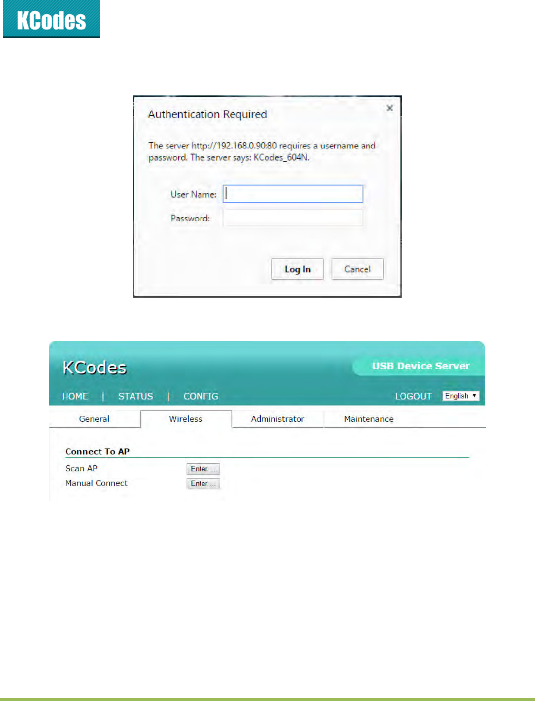
5. Login with administrator ID (default: admin) and its password (default: admin).
6. Click Wireless icon.
7. Thee ae to as to oet to ieless etok. Oe is “a AP, the othe is Maual
oet.
8. B “a AP, lik Ete ad hoose the ““ID ou at to oet. Afte selet, ou hae to
enter the password.
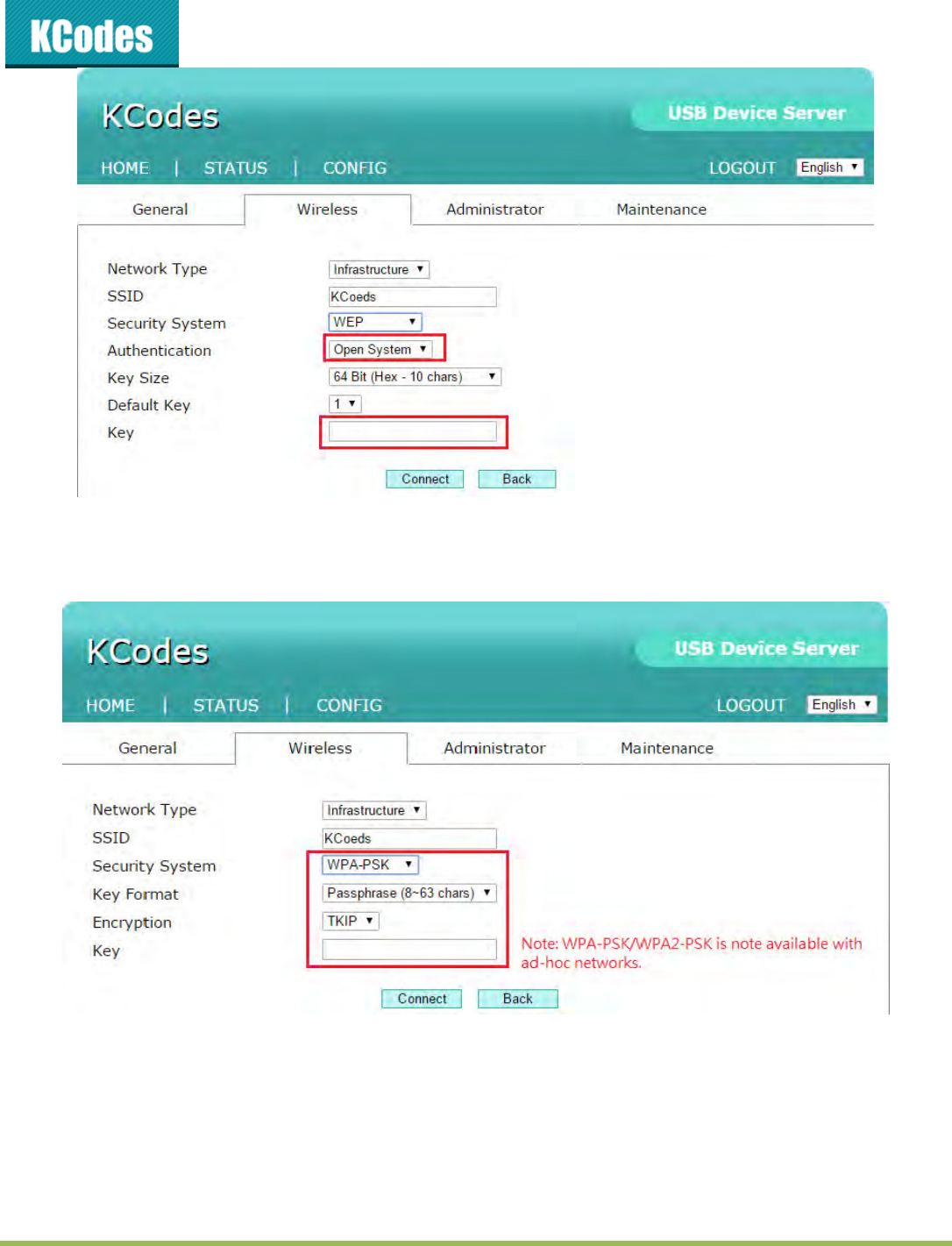
9. By Maual oet, to join an existing wireless network, you have to set the correct SSID, and
the correct security method with the correct key information.
10. If the wireless network is secured by WEP64 or WEP128, key index and WEP key must be set
correctly.
© 2014 KCodes Corporation. All rights reserved. 6 Series v2 User’s Manual V1.0
11. If the wireless network is secured by WPA-PSK or WPA2-PSK, the key formats, shared key and
encryption must be set correctly.
12. Click Submit to save your settings. And the server will reboot.
13. You have now finished the procedure of setting the wireless parameters
After properly configuring the wireless parameters, you can remove the network cable and reboot
the 601n/604n. 601n/604n will then connect to your wireless network. 601n/604n will detect if a
network cable is plugged-in or not. If a network cable is plugged-in, 601n/604n will always connect to the

© 2014 KCodes Corporation. All rights reserved. 6 Series v2 User’s Manual V1.0
network through the network cable. Otherwise it will always connect to the network through wireless
module.
Once 601n v2/604n v2 connects to the network, either by network cable or by wireless module, all
operations to use USB device server are exactly the same.
3.3. Assigning an IP Address to the Server
3.3.1. Preliminary
If you have a DHCP server on your network, your Server will receive an IP address
automatically. The IP address will then appear on the Control Center or on the page of
configuration report that you printed earlier. If your DHCP server does not give an IP address
to the Server, the Server will use the automatic private IP addressing IP: 169.254.0.0. ~
169.254.255.255
If you are not working in a DHCP network, you need to manually set the Server’s IP address.
3.3.2. IP Address
Unless you are assigning an IP address using DHCP, you must obtain an unused IP address
from your network administrator.
3.3.3. Methods for Setting the IP Address
You can set the IP address of your Server using one of the following methods, depending on your network
operating environment:
Automatic IP Address Assignment
Manual IP Address Assignment
3.3.4. Server Names and Server Name Rules
The default see ae of the “ee is KC6 fo 6 o KC64 fo 64 o KC6 fo 6 o
KC64 fo 64. If ou put to o oe “ees i ou loal aea etok, to aoid usig the sae
server names you have to change the server names by using the Control Center or the Serve’s e pages.
If your server name is longer than 15 characters, the Server uses only the first 15 characters.
3.3.5. Setting the IP Address Using DHCP
Follow the instructions below to get an IP address using DHCP:
© 2014 KCodes Corporation. All rights reserved. 6 Series v2 User’s Manual V1.0
1. Edit or create a scope in the DHCP manager of the DHCP daemon. The entries included in this scope
should contain the following parameters:
range of IP addresses
subnet mask
default router IP address
DNS server IP address
lease duration
2. Activate the scope. The Server automatically gets the DHCP parameters. If you are using DNS, you
may include at least one DNS server IP address in the DHCP scope or manually set the DNS server IP
addess usig “ee’s e pages o the Cotol Cete.
3.3.6. Setting the IP Address Using the Control Center
1. Install the Control Center. The Control Center is available on the Product CD.
2. Start the Control Center and Auto-searching Server window will appear.
3. If the tool finds multiple Servers in your local area network, then you have to select one Server from
the Server List.
4. Doule lik the highlighted see o lik the Cofigue “ee utto to get the see’s e
pages. Click CONFIG icon.
5. Login with administrator ID (default: admin) and its password (default: admin).
© 2014 KCodes Corporation. All rights reserved. 6 Series v2 User’s Manual V1.0
6. Click the button corresponding to your choice of IP setting methods (static or dynamic using DHCP).
When assigning a static IP address you also have to define Subnet Mask.
7. Click Submit to save your settings. And the Server will reboot. You have now finished the procedure
of setting the IP address.
Chapter 4 Using the USB Device Server
4.1. Introduction
The goal of this produce is to provide the USB device server in a single product. We developed a new
teholog alled NetU“B to ahiee this goal. Basiall, the NetU“B is a U“B oe IP teholog
that taspaetl ediets all U“B pakets to TCP/IP etok hael. NetU“B allos ou to use U“B
devices as if they were connected directly to your PC although they are actually remotely connected to
the 601/601n/604/604n USB device server.
4.2. Connect & Disconnect
NetU“B allos ou to use U“B deies as if the ee oeted dietl to ou PC although the ae
atuall eotel oeted to the 6/6/64/64 U“B deie see. The oet opeatio is a
© 2014 KCodes Corporation. All rights reserved. 6 Series v2 User’s Manual V1.0
software operation that simulates an actual USB device plug-i. That is to sa, he ou do a oet
opeatio i the Cotol Cete, PC a the detet a U“B deie’s plug-in, although actually you do not
plug i a U“B deie. “iilal, the disoet opeatio is a softae opeatio that simulates the
disconnection of the USB device. Once the connect operation is successful, the operations to use that
USB device are just the same as if the USB device is directly connected to the PC.
If a U“B deie is oeted a PC, e sa that PC has the ownership of the USB device. Only one PC
can get the ownership of a USB device at the same time. Therefore, if a USB device is connected by one
PC, no other PC can connect this USB device until this USB device is disconnected.
4.3. Subnet Issue
Before using the NetUSB technology, you must first make sure that your PC can access USB device server
ia TCP/IP. The siplest a to do this is usig Cotol Cete to seah fo the U“B deie see o
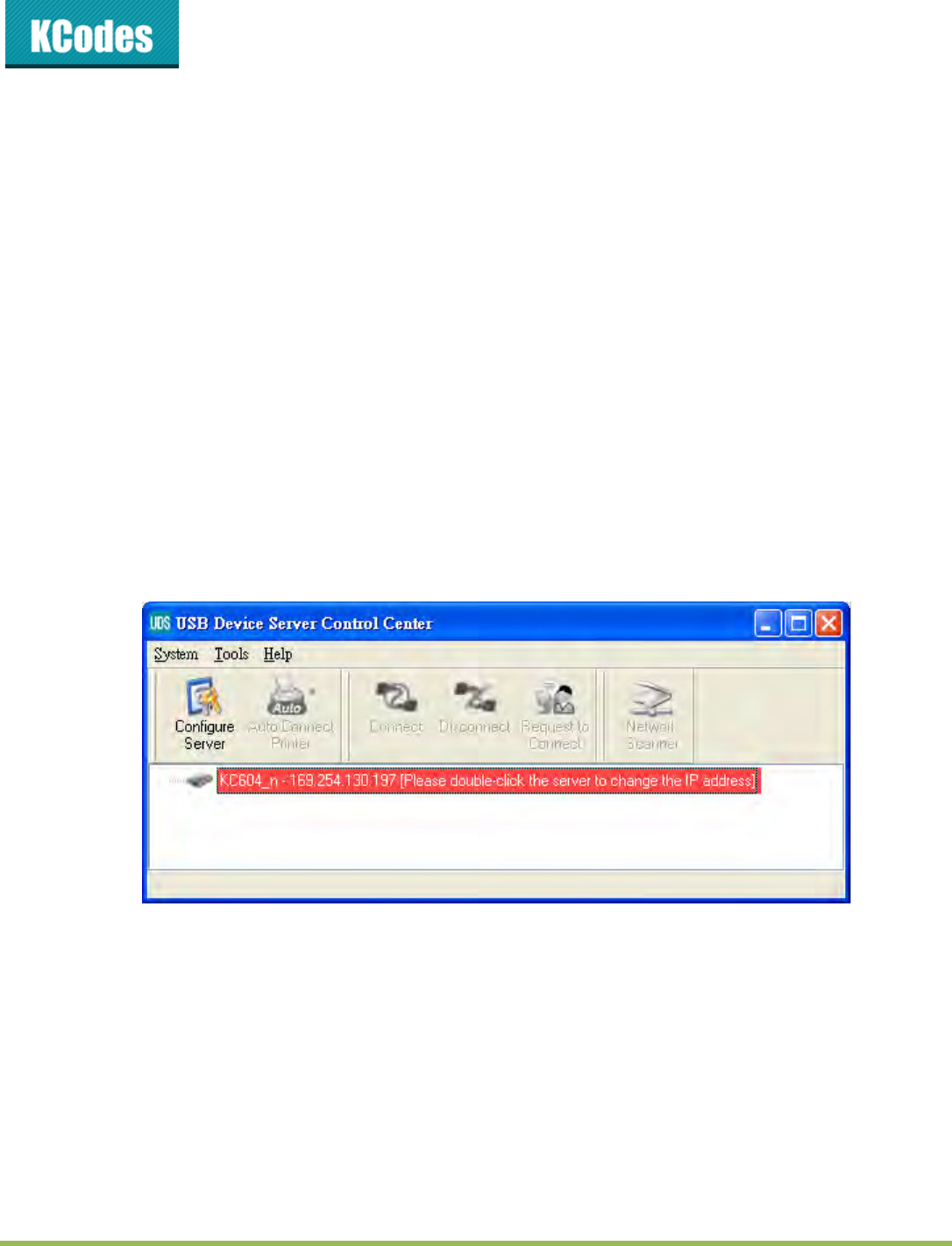
the network and change its IP address to be the same subnet as your PC. If the server and your PC are not
in the same TCP/IP subnet, Control Center will show the server in red, as the following figure. You must
change the IP address (or using DHCP) of the server so that the server and your PC are in the same subnet.
Control Center will show these servers in blue, meaning you can access these servers by the NetUSB
technology.
4.4. Installation of USB Device Driver
Some USB devices, like printers or MFPs (multifunction printers), require to install vendor-supplied driver
(usually on CDROM). For those USB devices that do not need to install driver, please skip this section.
1. Iset the CDROM ito the CD die ad u the autou poga.
2. Follow the instructions of the installation program to install driver.
3. When the installation program asks you to plug-i the U“B deie, u the Cotol Cete.
4. In the Control Center, click the USB device server that has the desired USB device attached.
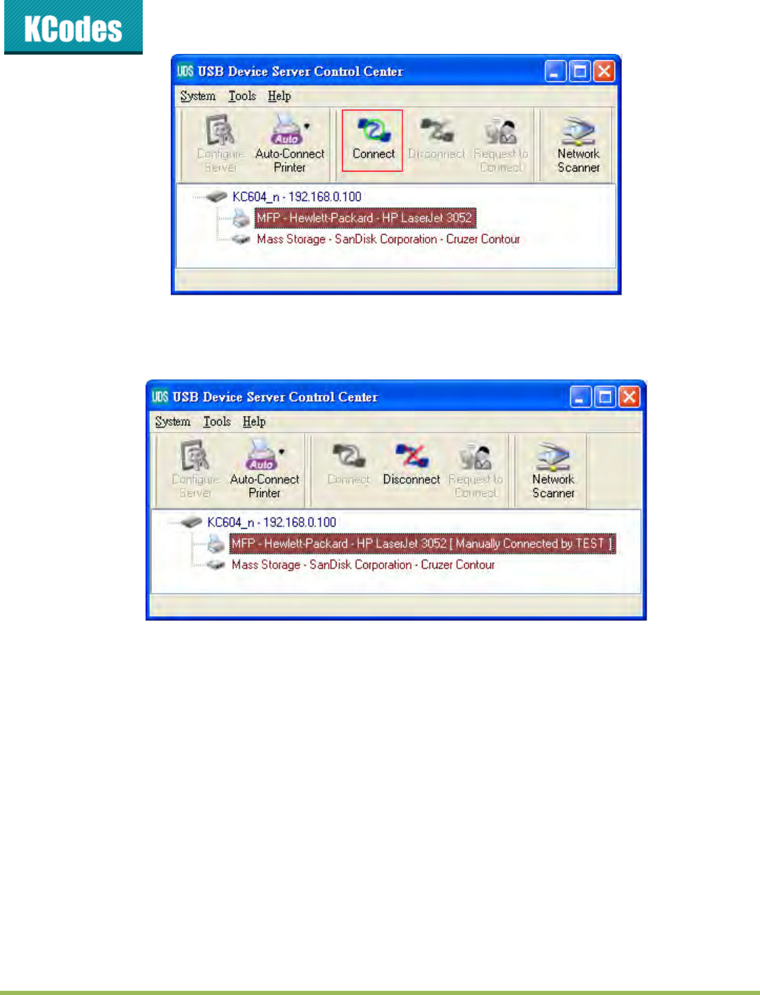
5. Click the desired USB device as the following figure.
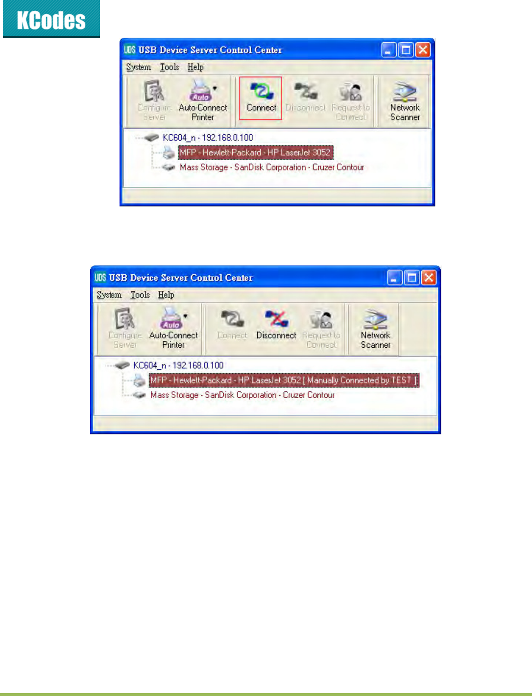
© 2014 KCodes Corporation. All rights reserved. 6 Series v2 User’s Manual V1.0
6. Clik the Coet utto. The the essage Mauall Coet ou_opute_ae ill
be shown, as the following figure.
7. Now, the installation program will detect the USB device and continue to install driver.
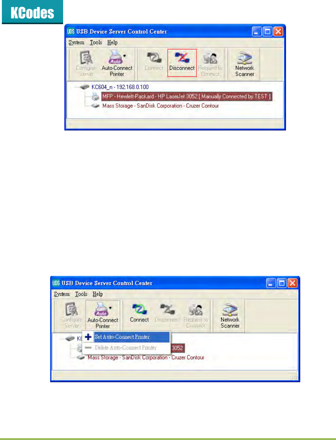
8. After the installation is completed, click the USB device in the Control Center and then click the
Disoet utto to disoet the U“B deie.
Now the driver of your USB device is installed.
4.5. Using the USB Device Server
1. In the Control Center, click the USB device server that has the desired USB device attached.
2. Click the desired USB device.
© 2014 KCodes Corporation. All rights reserved. 6 Series v2 User’s Manual V1.0
3. Clik the Coet utto. The the essage Mauall Coet ou_opute_ae ill
be shown.
4. Now, PC will detect the plug-i of the U“B deie. The oet opeatio is a softae opeatio
that simulates an actual USB device plug-i. That is to sa, he ou do a oet opeatio i
the Cotol Cete, PC a the detet a U“B deie’s plug-in, although actually you do not plug in
any USB device.
5. Then, just use the USB device as if it is connected dietl to ou PC’s U“B pot.
6. After you finish using the USB device, click the USB device in the Control Center and then click the
Disoet utto to disoet the U“B deie. Othe PCs a ot Coet the U“B deie
util ou Disoet that U“B deie. That is to sa, ol oe PC is alloed to oet the U“B
device at the same time.
© 2014 KCodes Corporation. All rights reserved. 6 Series v2 User’s Manual V1.0
4.6. Auto-Connect Printer
The method described in section 4.5 is so-called manual-connect, which means users must manually
connect the USB device before using that device, and must manually disconnect the USB device after
using the device, otherwise nobody else can connect this device. However, for printers and scanners (and
MFPs), the USB device server supports auto-oet so uses do’t eed to auall oet/disoet.
This and the next sections show you how to do this.
After the driver is installed as described in section 4.4, you can see a newly created printer in the Control
Pael’s Pites ad Faes. Follow the steps below to do a NetUSB auto-connect printing.
1. In the Control Center, click the USB device server that has the desired printer (or MFP) attached.
2. Click the desired printer (or MFP).
3. Clik the Auto Coet Pite utto ad hoose “et Auto-Coet Pite.
The following figure will appear.
© 2014 KCodes Corporation. All rights reserved. 6 Series v2 User’s Manual V1.0
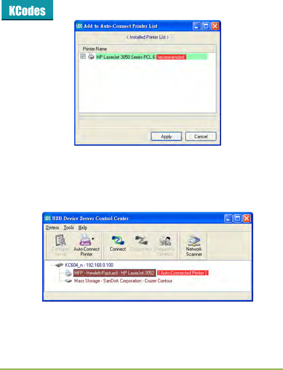
4. Choose the desired printer. The desired printer must be the Windows printer (this is a logical
printer) that matches the printer attached on the USB device server (this is a physical printer).
The lik the Appl utto.
5. The, the pite ill e aked as a Auto-Coeted Pite i ed. If ou hoose Auto-
Coeted Pite List i the Tools eu, ou a see a el eated ite that desies the
association between the Windows printer and the physical printer on the server.
© 2014 KCodes Corporation. All rights reserved. 6 Series v2 User’s Manual V1.0
6. Then try to issue a print job to the desired printer. You will see the Control Center will
automatically do a connect operation. Then, the print job will be issued to that printer.
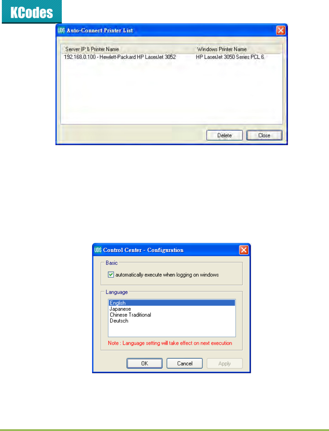
7. Even you already properly setup an auto-connected printer, the Control Center must be running
i the akgoud hile a pit jo is issued. This eas ou’d ette u the Cotol Cete
every time after you login Windows. In order to skip this manual operation, you can make the
Control Center be run automatically after you login Windows. To do this, choose the
Cofiguatio ite i the Tools eu. The folloig ido ill appea. Clik o the hek
o ad the o the OK utto. This featue is ealed default.
If you would like to break the association between the Windows printer and the physical printer, just click
o the assoiatio ad lik the Delete utto i the Auto-Coeted Pite List.
© 2014 KCodes Corporation. All rights reserved. 6 Series v2 User’s Manual V1.0
4.7. Network Scanner
For NetUSB scanning, we recommend you use Network Scanner as the following steps.
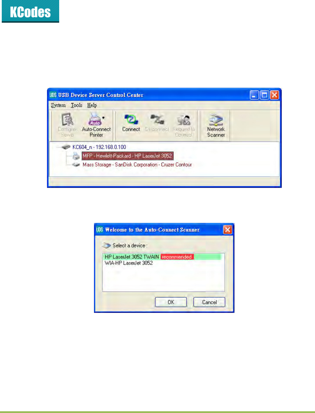
1. In the Control Center, click the USB device server that has the desired MFP (or scanner) attached.
2. Click the desired MFP (or scanner).
3. Clik the Netok “ae utto. The ou a see that the Cotol Cete ill automatically
do a oet opeatio. The folloig ido ill appea.
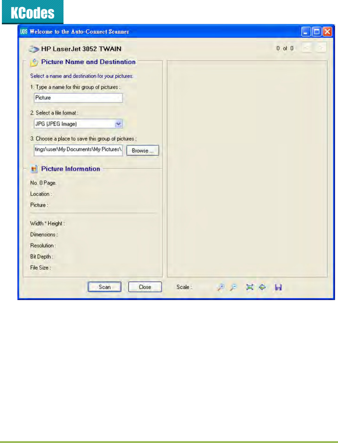
4. Choose oe of TWAIN o WIA ite. Clik OK. The folloig ido ill appea.
© 2014 KCodes Corporation. All rights reserved. 6 Series v2 User’s Manual V1.0
5. Follow the usual steps to do scanning.
6. Afte the saig, lose the Auto-Coet “ae ido. At this oet, Cotol Cete
will automatically do a disconnect.
4.8. USB Storage
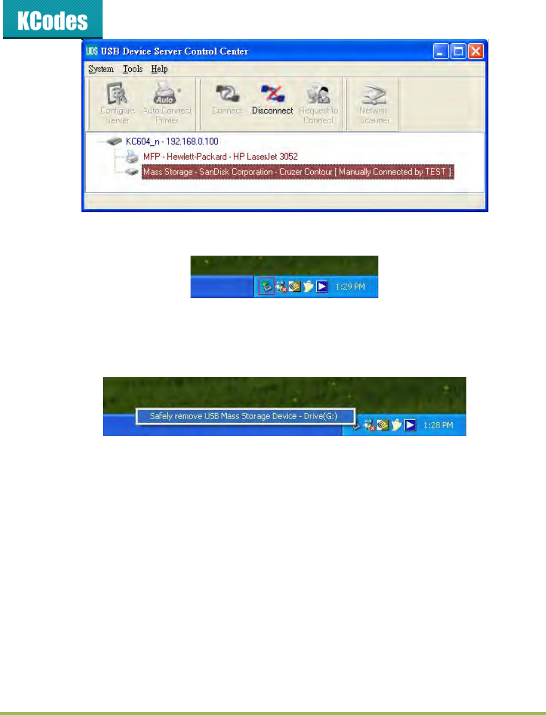
You ust use auall oet fo U“B stoage. Afte ou oet a U“B stoage, like the folloig
picture, your PC ill hae a e disk. If the U“B stoage is a flash die, the e disk is a eoale disk.
© 2014 KCodes Corporation. All rights reserved. 6 Series v2 User’s Manual V1.0
You can see the storage icon in the system tray.
Then just use the new disk as a general disk. After you finish the disk operations, click the storage icon in
the sste ta ad hoose “afel eoe U“B Mass “toage Deie to eoe the U“B stoage, as the
following figure.
The, i the Cotol Cete, lik the U“B stoage deie ad lik the Disoet utto to disoet
the USB storage device.
4.9. Request to Connect
If a USB device is manually connected by any other user, basically you can not connect that device.
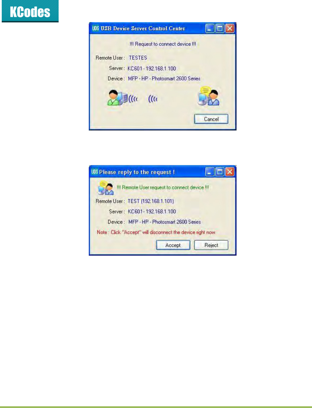
Hoee, e offe aothe ehais alled Reuest to Coet to sole this ioeiee. Fo
example, there are two computers – TESTES ad TE“T. No the oe of HP Photosat 6 is TE“T.
Then, the TESTES computer wants to use this HP printer. The user on the TESTES computer can click the
Reuest to Coet utto i the Cotol Cete. The folloig ido appeas.
© 2014 KCodes Corporation. All rights reserved. 6 Series v2 User’s Manual V1.0
At this moment, the user on the TEST computer will see the following window, indicating that another
computer – TESTES is requesting to use the HP printer.
The user will choose to accept or reject. If accepted, the Control Center on TEST will automatically
disconnect the device and the Control Center on TESTES will automatically connect that device.
4.10. Quitting the Control Center
The Cotol Cete does’t eall uit if ou lik the X o lose o at the top ight oe of the
window. Instead, it just minimizes itself to the system tray. There are two ways to really close the Control
Cete. The fist a is hoosig Eit ite i the File eu i the Cotol Cete. The seod a is
right-clicking the icon of the Control Center in the system tray and choosing the Eit ite

© 2014 KCodes Corporation. All rights reserved. 6 Series v2 User’s Manual V1.0
4.11. Limitations
There are some limitations to use the NetUSB technology.
1. Only supports Windows XP/2003/Vista/7/8. Windows 98/ME is not supported.
2. Only one PC can get the ownership of the same USB device at the same time.

© 2014 KCodes Corporation. All rights reserved. 6 Series v2 User’s Manual V1.0
Chapter 5 File Server
This chapter describes the file server function of the Server which allows USB storage devices to be shared
across a network by using SMB: NetBIOS over TCP/IP and FTP protocol.
5.1. Preliminary
1. This product supports a file format of FAT32 ad NTF“. Hoee, the ite opeatio o NTF“ is
only supported in NetUSB mode. Please refer to the NetUSB Mode.
2. Corporation is not responsible for the loss or corruption of data in memory devices, including hard
disk; Corporation is not responsible for the leak, manipulation, loss, or corruption of data in
memory devices connected to the Server after unauthorized access.
3. In order to use the USB Mass Storage device connected to the Server, the SMB protocol or FTP
protocol must be set up.
© 2014 KCodes Corporation. All rights reserved. 6 Series v2 User’s Manual V1.0
5.2. Connecting USB Mass Storage to the Server
5.3. Supported Codepages
- What is codepage?
Used by the system to encode and interpret string characters. Codepage formats are not the same for
each language. Some languages, such as Japanese have multibyte characters, while others, such as
English and German, need only one byte to represent each character.
- Filename Encoding of FAT File System
This is known as an 8.3 file name, a short file name using codepage encoding. The FAT file system also
supports file names that can be up to 255 characters long. This is known as a long file name using Unicode
(UTF-16) encoding.
- When do you need to configure codepage?
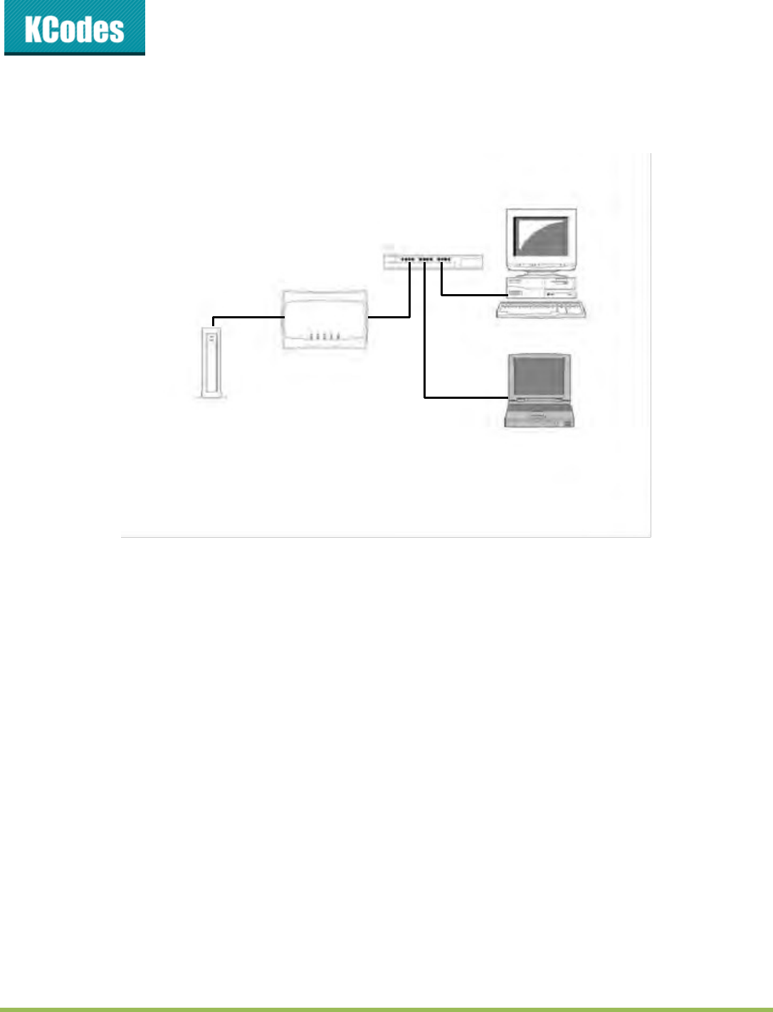
LAN HUB/Switch
Storage
The Server
© 2014 KCodes Corporation. All rights reserved. 6 Series v2 User’s Manual V1.0
The Server supports Windows codepages. If users want to communicate files using FTP client tool or SMB
on Windows 98/Me/2000 with the Server, they have to set their Server codepage to be same as the
codepage that their Windows PC is using.
1. FTP
2. SMB on Windows 98/Me/2000
- Cofiguig the “ee’s Codepages
Users can use the following methods to set the “ee’s odepage.
1. Start Control Center and Auto-searching Server window will appear.
2. If the tool finds the Servers in your local area network, select the Server from the Server List and
lik Cofigue “ee utton.
3. The We aage ill sho, lik the Cofig utto ad ete the “ee’s adiistato
(default: admin) and password (default: admin).
4. After you have logged in successfully, setting General configuration dialog appears.
5. Select your codepage form File Server Codepage box and click Apply.
5.4. Using Shared Storages by SMB/CIFS Method for Windows
1. Connect a USB storage device to this product.
2. Select My Network Places.
3. Click Display the Computers of Workgroup.
4. Double click Microsoft Windows Network icon.
5. Double click the Workgroup that the Server belongs to. The default Workgroup name is
WORKGROUP. You a efe to Cotol Cete o the “ee’s e pages to get it. You ill see
that the Server is displayed as its server name.
6. If you cannot find Workgroup name of the Server in Microsoft Windows Network, you can select
“eah fo Copute… i M Netok Plaes ad ete the “ee Name of the Server to find it.
7. Double click this Server Name icon.
8. If you clear Enable SMB/CIFS Print/File Server Authentication in Supported Protocols, you login to
the SMB server without requiring authentication; otherwise you have to enter user name and

© 2014 KCodes Corporation. All rights reserved. 6 Series v2 User’s Manual V1.0
password to login to the Server. You can add user name and password in User Account box by the
Cotol Cete o the “ee’s Web page.
Note: If you use SMB on Windows 98 SE/ME, you must login to your Windows 98 SE/ME
usig the sae use ae as i the “ee’s Use Aout.
9. The shared folders will be listed as USB1_DyPz, and USB2_DyPz where Dy represents the y-th disk
and Pz represents the z-th partition with respect to USB1 port and USB2 port.
10. Perform Open, Paste, Remove or Copy the files to the shared folders.
5.5. Using Shared Storage by FTP Methods for Windows
Use Microsoft IE to the shared USB Mass Storages
1. Open Microsoft IE
2. In Web Address List, ete oad: ftp://“ee’s “ee Nae o ftp://“ee’s IP addess.
If you have changed the default FTP port : 21 to the new value, you have to add the new port
ue i the tail of oad as ftp://“ee’s “ee Nae: ftp pot o ftp://“ee’s IP
addess: ftp pot.
3. If you set Enable Server Authentication in FTP server protocol settings you have to enter user
name and password to login to the Server; if you set Allow Anonymous Login, you can use the
use ae aoous to login with Read-only permission. If you clear Server authentication,
you do not need username or password to login to the Server. You can add user name and
passod i Use Aout o the Cotol Cete o the “ee’s We pages.
4. The shared folders will be listed in IE.
5. Perform Paste, Remove or Copy the files to the shared folders.
Use Miosoft Dos’s FTP liet
1. Ete Dos oad ftp.
2. Ete ope see’s “ee Nae o ope see’s IP addess. If ou hae haged the default
FTP port : 21 to the new value, you have to add the new port number in the tail of command as
ope see’s “ee Nae ftp pot o ope see’s IP addess ftp pot .
3. If you set Enable Server Authentication in FTP server protocol settings you have to enter user
name and password to login to the Server; if you set Allow Anonymous Login, you can use the
use ae aoous to logi ith Read-only permission. If you clear Server authentication,
you do not need username or password to login to the Server. You can add user name and
password in User Account box the Control Cete o the “ee’s We pages.
4. Perform FTP commands to use this FTP server.
© 2014 KCodes Corporation. All rights reserved. 6 Series v2 User’s Manual V1.0
Chapter 6 The Server’s Web Pages
6.1. Introduction
The Server runs the http server, httpd on TCP port: 80. Users may use the web pages to see the “ee’s
system status and configure the Server.
6.2. Using the Server’s Web Pages
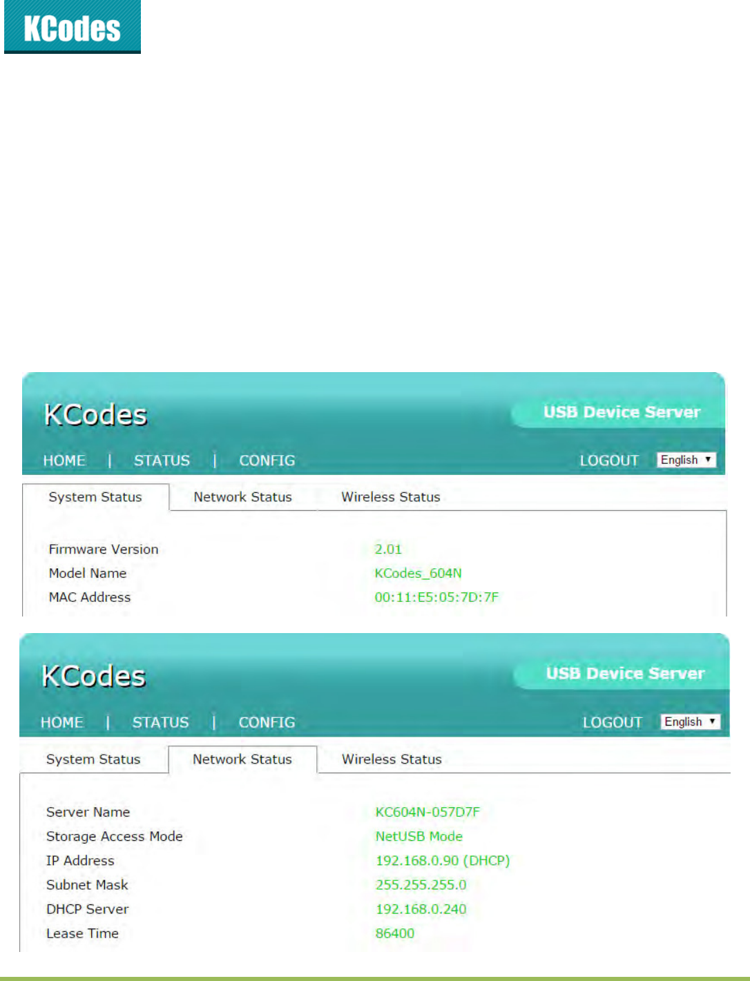
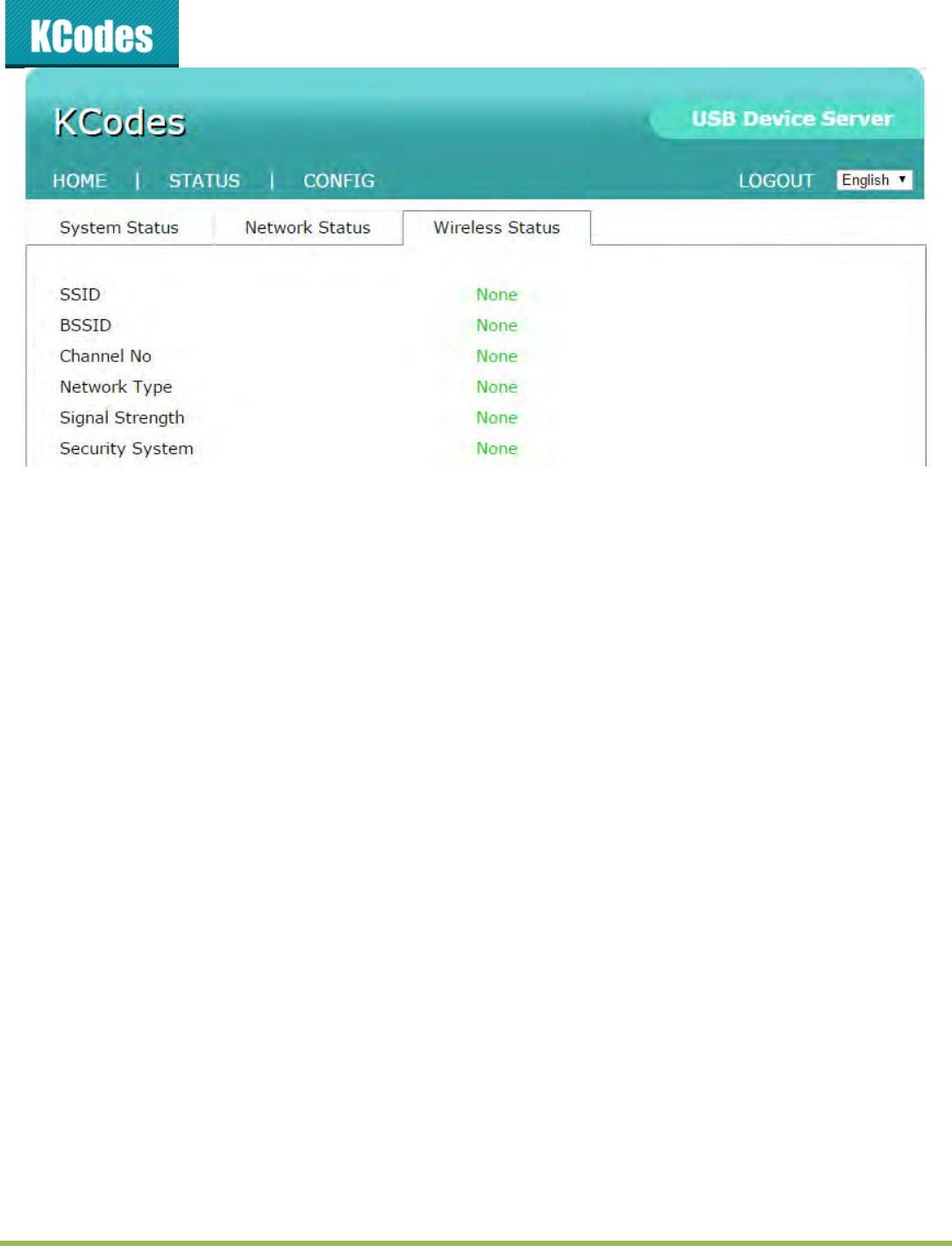
6.2.1. Displaying Server Status
Clik o the “TATU“ io to see sste status, etok status ad Wieless “tatus (only for 601n/604n).
© 2014 KCodes Corporation. All rights reserved. 6 Series v2 User’s Manual V1.0
6.2.2. Setting up Server Configuration
To set up the “ee ofiguatio, lik o the CONFIG io ad the the sste ill euest use to
enter administrator (default: admin) and password (default: admin) to login.
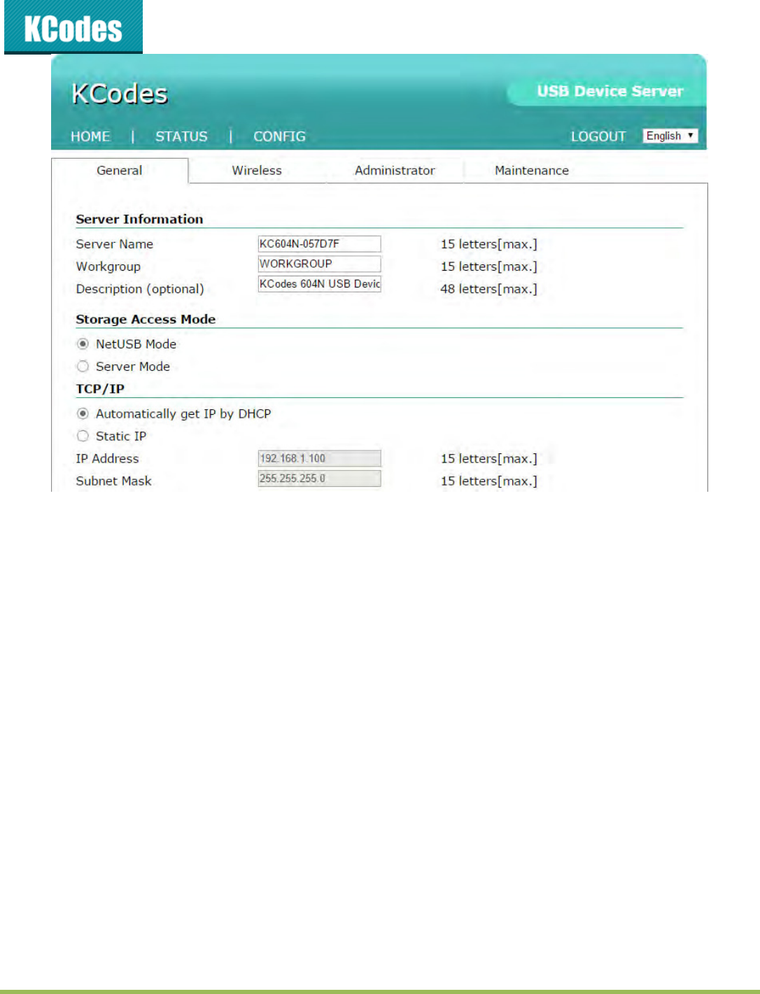
General Configuration
Server Information: You have to set the Server Name, which is the name to represent the Server.
TCP/IP: You have to set the Server’s TCP/IP configuration to connect TCP/IP network. Please see
Chapter 3 Basic Installation for more details.
Storage Access Mode: Set storage access mode as server or NetUSB mode.
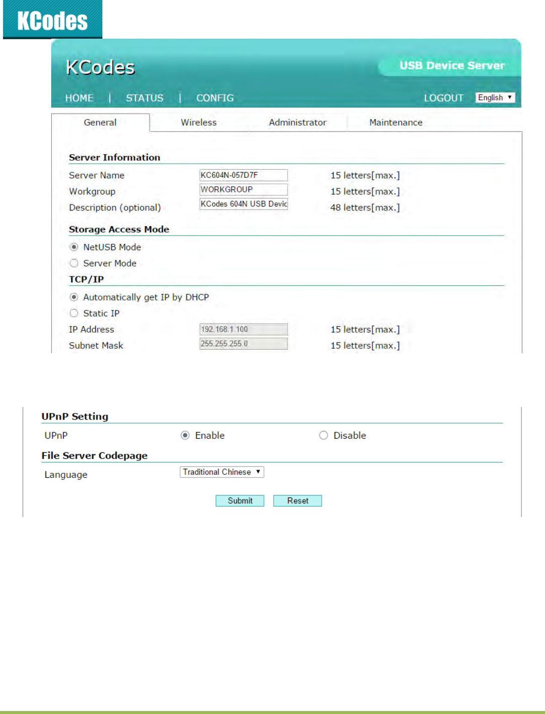
© 2014 KCodes Corporation. All rights reserved. 6 Series v2 User’s Manual V1.0
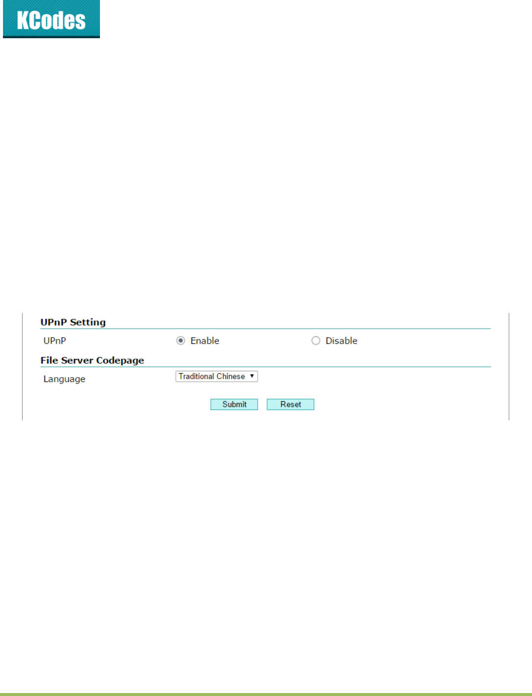
UPnP Setting: Enable or disable the UPnP function.
File Server Codepage: Setup language for file server code.
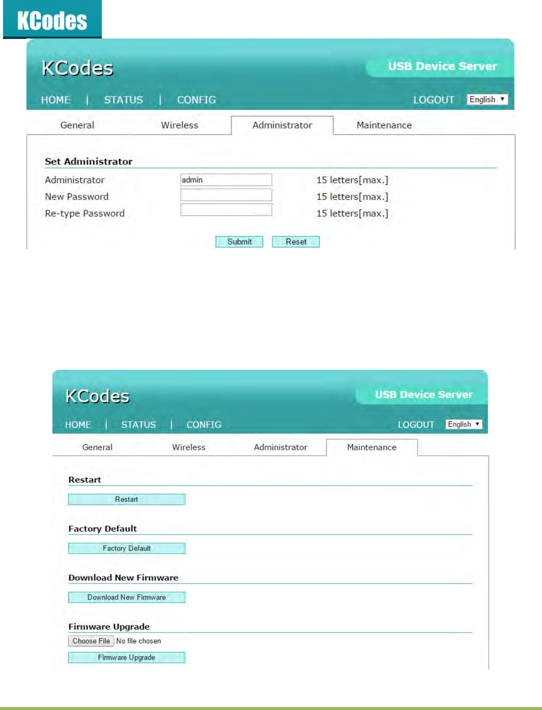
Administrator: You can change administrator name and password. If you forgot administrator
name and password, you must perform Restore Factory Default action by plugging in the power
adaptor while pressing the Init button. Please refer to the chapter “Restore Factory Defaults.
Administrator: enter your desired administrator name.
New Password: enter your desired password.
Re-type Password: re-confirm the password.
© 2014 KCodes Corporation. All rights reserved. 6 Series v2 User’s Manual V1.0
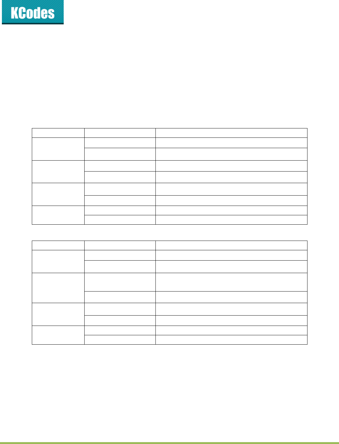
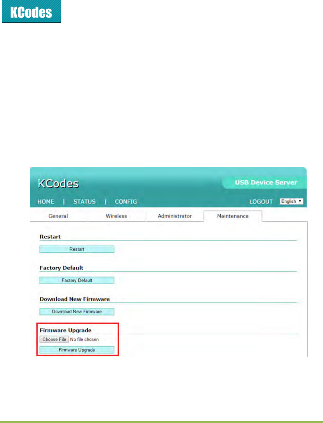
Maintenance If you want to restore factory default values of the Server or upgrade new
firmware, you can use the Maintenance tool.
Restart: click this button to restart (reboot) the Server.
Factory Default: click this button, the Server will restore factory default values.
Firmware Upgrade: click Browse to find the firmware file to be upgraded. Click
Upload to upload the firmware into the Server.
© 2014 KCodes Corporation. All rights reserved. 6 Series v2 User’s Manual V1.0
Chapter 7 Troubleshooting
This chapter provides useful information to help you resolve difficulties that you may experience with your
Server. Fault symptoms, possible causes, and remedial actions are provided within a quick reference table.
This “ee’s U“B pots ol suppot MFPs, pites, saes, ass stoage, ad U“B aeas.
7.1. LED Indicators
601 v2/604 v2
Indicators
Behavior
Description
Power
On
Power On
Off
Power off/System error
Link
On
Network connected
Off
No physical connection to network
Status
Blinking
Activity on network
Off
No activity on network
USB
On
USB device connected
Off
No physical connection to USB device
601n v2/604n v2
Indicators
Behavior
Description
Power
On
Power On
Off
Power off/System error
WLAN
Blinking
Wireless Network connected
(No LAN connected)
Off
No activity on Wireless Network
LAN
Blinking
Activity on network
Off
No activity on network
USB
On
USB device connected
Off
No physical connection to USB device

© 2014 KCodes Corporation. All rights reserved. 6 Series v2 User’s Manual V1.0
7.2. Firewall
If a firewall software has been installed on your PC, it may block the communication between the PC and
the USB device server so that the USB device server can not work properly. To solve this problem, either
disable the firewall or configure the firewall to allow the following TCP and UDP ports:
7303, 7305, 7411, 20005
© 2014 KCodes Corporation. All rights reserved. 6 Series v2 User’s Manual V1.0
Chapter 8 Restore Factory Defaults
You a estoe the “ee’s default paaetes oe of the folloig ethods.
8.1. Using the Server’s Web Pages
1. Go to the Serve’s e page ad lik CONFIG
2. Enter administrator (default: admin) and password (default: admin).
3. Click Maintenance.
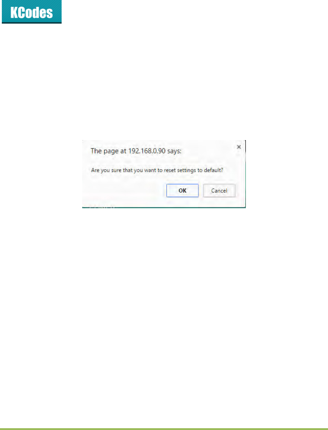
4. Click Factory Default.
5. Click Yes to confirm
8.2. Using Init Button
Turn on server and wait until you can see it on control center, press the initial button over 10 sec. Server
will automatically shutdown and restart, this process will take about 1 and half min , after restart server
will back to factory default.
8.3. Default Parameters List
General Information
Server Name: KC601 (for 601) or KC601n (for 601n) or KC604 (for 604) or KC604n (for 604n)
TCP/IP
Automatically get IP by DHCP: Enabled
Static IP: Disabled
- IP Address: 192.168.1.100
- Subnet Mask: 255.255.255.0
User Accounts
Administrator: admin
Password: admin
© 2014 KCodes Corporation. All rights reserved. 6 Series v2 User’s Manual V1.0
Chapter 9 Upgrade Firmware
This chapter describes how to upgrade firmware. Please follow the following Procedures:
9.1 Using the Control Center
1. Open Control Center. It will automatically search the existing Servers and display their statuses.
2. Select the Server that you want to upgrade the firmware. Double click the selected Server to get the
see’s ai e page.
3. Click CONFIG icon.
4. Login the Server with Administrator (default: admin) and Password (default: admin).
5. Click Maintenance.
6. Click Upgrade Firmware.
7. Click Browse button to choose the file of new firmware.
8. Click Upload button to start firmware upgrade.
9. The server will reboot.

© 2014 KCodes Corporation. All rights reserved. 6 Series v2 User’s Manual V1.0
Chapter 10 The Init Button
The Init button is used for maintenance: Simultaneously press Init button and turn on (by plugging in the
power adaptor) the Server will reboot. (For 601/601n, only USB LED indicator will blink.) After that, the
Server will do the following tasks:
Perform a Factory Default restoration of the server, which will restore most of the
parameters and settings to factory default values.
Note: After performing the tasks mentioned above, you have to plug off the power adaptor and then plug
in the power adaptor to restart the Server.

© 2014 KCodes Corporation. All rights reserved. 6 Series v2 User’s Manual V1.0
FCC Statement
Federal Communication Commission Interference Statement
This equipment has been tested and found to comply with the limits for a Class B digital device,
pursuant to Part 15 of the FCC Rules. These limits are designed to provide reasonable protection
against harmful interference in a residential installation. This equipment generates, uses and can
radiate radio frequency energy and, if not installed and used in accordance with the instructions, may
cause harmful interference to radio communications. However, there is no guarantee that interference
will not occur in a particular installation. If this equipment does cause harmful interference to radio or
television reception, which can be determined by turning the equipment off and on, the user is
encouraged to try to correct the interference by one of the following measures:
● Reorient or relocate the receiving antenna.
● Increase the separation between the equipment and receiver.
● Connect the equipment into an outlet on a circuit different from that to which the receiver is
connected.
● Consult the dealer or an experienced radio/TV technician for help.
FCC Caution: Any changes or modifications not expressly approved by the party responsible for
compliance could void the user’s authority to operate this equipment.
This device complies with Part 15 of the FCC Rules. Operation is subject to the following two
conditions: (1) This device may not cause harmful interference, and (2) this device must accept any
interference received, including interference that may cause undesired operation.
For product available in the USA/Canada market, only channel 1~11 can be operated. Selection of
other channels is not possible.
This device and it's antennas(s) must not be co-located or operating in conjunction with any other
antenna or transmitter except in accordance with FCC multi-transmitter product procedures.
For MPE Statement – Mobile device
IMPORTANT NOTE:
FCC Radiation Exposure Statement:
This equipment complies with FCC radiation exposure limits set forth for an uncontrolled
environment. This equipment should be installed and operated with minimum distance 20cm between
the radiator & your body.