KEBA 0001 RFID transceiver working at 13.56 MHz User Manual xe020 tden
KEBA AG RFID transceiver working at 13.56 MHz xe020 tden
KEBA >
internal technical description

RFID-Module Introduction
Kemro K2
XE 020 RFID-Module
Internal Technical Documentation V 1.0

Introduction XE 020
List of changes
Version
changed
from / to
Date Description Modified
by
1.0 07-2007 Created
1.1 April, 11th
2008 Additional correction hsm

RFID-Module Introduction
Contents
1 Introduction...................................................................................................................6
1.1 Purpose of the document.....................................................................................6
1.2 Audience and prerequisites.................................................................................6
1.3 Intended use........................................................................................................6
1.4 Notes on this document.......................................................................................7
1.4.1 Contents of document..............................................................................7
1.4.2 Not contained in this document................................................................7
1.5 Documentation for further reading.......................................................................8
2 Safety notes..................................................................................................................9
2.1 Representation....................................................................................................9
3 Product overview........................................................................................................10
3.1 Summary...........................................................................................................10
3.1.1 Range and detection..............................................................................11
3.2 RFID module before installation.........................................................................11
3.3 RFID module after installation...........................................................................12
4 Assembly and installation notes...............................................................................13
4.1 Minimum XE 020/ANT antenna module clearance.............................................13
5 Connections and wiring.............................................................................................15
5.1 EMC and wiring guidelines................................................................................15
5.1.1 Personal safety......................................................................................15
5.1.2 Why EMC-aware wiring?.......................................................................15
5.1.3 Which EMC measures must be taken?..................................................15
5.2 Power supply.....................................................................................................15
5.3 XE 020/A and XE 020/ANT module interfaces...................................................16
5.3.1 Connector for coaxial antenna cable (1 and 3).......................................16
5.3.2 Connector for status LED (2 and 5)........................................................16
5.3.3 XE 020/A module RJ45 socket (4).........................................................16
5.4 Cables...............................................................................................................18
5.4.1 Coaxial antenna cable...........................................................................18
5.4.2 Connector cable for RFID status LED....................................................18
5.4.3 Connector cable for RFID module / OP 3xx...........................................18
6 Configuration..............................................................................................................19
6.1 RFID module DIP switch....................................................................................19
7 Status display.............................................................................................................20
7.1 RFID status LED...............................................................................................20
7.1.1 Boot-time behaviour...............................................................................20
8 Maintenance and repair notes...................................................................................21
8.1 Maintenance......................................................................................................21

Introduction XE 020
8.2 Repair................................................................................................................21
8.2.1 Packaging and shipping.........................................................................21
8.3 Waste disposal..................................................................................................21
9 Accessories and spares.............................................................................................22
10 Technical specification...............................................................................................23
11 Relevant EC directives and applicable standards....................................................24
11.1 EC directives.....................................................................................................24
11.2 Standards..........................................................................................................24
11.2.1 Validating conformance to the R&TTE directive...................................24
11.2.2 Other standards...................................................................................24
11.2.3 USA standards.....................................................................................24

RFID-Module Introduction

Introduction XE 020
1 Introduction
1.1 Purpose of the document
This planning manual describes the RFID XE 020/A module and the
XE 020/ANT antenna module, which are already permanently installed in
different KEBA operating panels. The application and functionality of the
RFID module is the same for each operating panel.
1.2 Audience and prerequisites
The planning manual is geared towards those who are using or intend to
deploy an operating panel with RFID module.
Only electrical technicians who are qualified to the VDE 1000-10 standard
are permitted to install and maintain the operating panel.
This means personnel who:
l can evaluate the work to be carried out and recognise the possible
hazards based on their technical training, knowledge and experience
plus their expertise in the applicable standards.
l have a level of knowledge equivalent to that obtained through
professional training as a result of several years experience working in
a similar field.
1.3 Intended use
The intended use of the XE 020 RFID module includes deployment in
KEBA operating panels. The module can also be installed in third party
devices provided chapter "Minimum XE 020/ANT antenna module
clearance" is taken into consideration.
The XE 020/A RFID (Radio Frequency Identification) module is used in
conjunction with an RFID card for contactless logon and logoff (as per ISO
15693) and is employed for user identification. This replaces the login of a
user with username and password.
The RFID module may not be used to fulfil protection requirements in the
area of personal safety to prevent a malfunction compromising personal
safety.

RFID-Module Introduction
1.4 Notes on this document
1.4.1 Contents of document
l RFID module description
l Assembly and installation notes
l Description of the connections and wiring including EMC measures
l Description of the configuration
l Description of the status display
l Maintenance notes
l Accessories
l Technical specification
1.4.2 Not contained in this document
l Operating panel description

Introduction XE 020
1.5 Documentation for further reading
The following is a listing of the planning manuals for an operating panel,
equipped with an RFID module:
Doc. No.: Planning
manual Description
1000520 OP 350/A-0013
- in preparation - OP 350-LD/C-0114
- in preparation - OP 360-LD/A-0013
- in preparation - OP 362-LD/C-0114
Describes the installation, assembly,
connection and operation of the operating
panel. Each planning manual also contains
programming and maintenance notes.
RFID-Module Safety notes
2 Safety notes
2.1 Representation
At various points in this manual you will see notes and precautionary warn-
ings regarding possible hazards. The symbols used have the following
meaning:
!
DANGER!
• indicates an imminently hazardous situation which, if noch avoided, will
result in death or serious injury.
!
WARNING!
• indicates a potentially hazardous situation which, if not avoided, could
result in death or serious injury..
!
CAUTION!
• means that if the corresponding safety measures are not taken a poten-
tially hazardous situation can occur which, if not avoided, may result in
property damage or slight bodily injury.
NOTICE
• NOTICE used without the safety alert symbol indicates a potentially
hazardous situation which, if noch avoided, may result in property
damage.
• This symbol reminds you of the possible consequences of touching
electrostatically sensitive components.
Information
Informations on use of equipment and useful practical tips are identified by
the symbol "Information". "Information" do not contain any information that
draws attention to potentially dangerous or harmful functions.
Product overview XE 020
3 Product overview
3.1 Summary
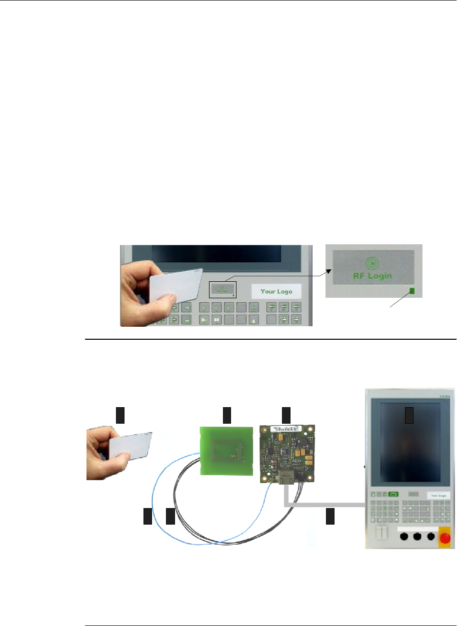
The RFID card user must hold the RFID card close to the RFID antenna on
the front of the operating panel for identification.
If the user's RFID card was recognised, the LED on the front panel turns
green.
The RFID module can also supply the data captured from the RFID card,
e.g. so that it can be further processed by the kemro.view.standard
program on the KEBA control.
RFID-Status-LED
Contactless user identification with an RFID card (e.g. operating panel)
An RFID system comprises:
567
1234
567
1.......RFID card
2.......XE 020/ANT antenna module
3.......XE 020/A RFID module (evaluation unit)
4.......Operating panel
5.......Coaxial antenna cable (max. 300 mm)
6.......Connector cable for RFID status LED
7.......Connector cable for RFID module / OP 3xx (max. 1 m)
RFID system components
RFID-Module Product overview
3.1.1 Range and detection
The typical range for RFID card to XE 020/ANT antenna module is 40 mm
for the recommended RI-I02112A-03 RFID card (assuming an aluminium
front panel).
The card is recognised when the RFID LED on the front of the operating
panel turns green (for 3 secs) (refer to chapter “RFID status LED“).
There is no provision to detect multiple cards at the same time. If several
RFID cards are within range, either only one will be detected or this will
cause a detection error, in which case the RFID status LED will turn red.
3.2 RFID module before installation
The RFID module consists of the following components:
LED-RT/GN
N1
O N
1 2
XE 020 ANT
XE 020/A
53
57 64
60
1
2
3
4
5
6
7
11
10 9
8
020XE 020/ANT antenna module
1.......Model identification label
2.......Connector for coaxial antenna cable
3.......Connector for LED cable
4.......RFID status LED
Cables
10.....Coaxial antenna cable (max. 300 mm)
11.....Connector cable for RFID status LED
XE 020/A RFID module
5........Connector for coaxial antenna cable
6........Connector for LED cable
7........RJ45 socket for shielded connection cable
(max. 1 m) between RFID module and OP
3xx
8........DIP switch for address settings
9........Model identification label
RFID module before installation
Product overview XE 020
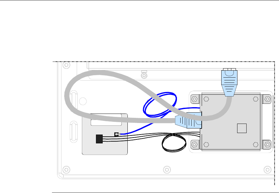
3.3 RFID module after installation
ANT LED
RFID
RFID module after installation
RFID-Module Assembly and installation notes
4 Assembly and installation notes
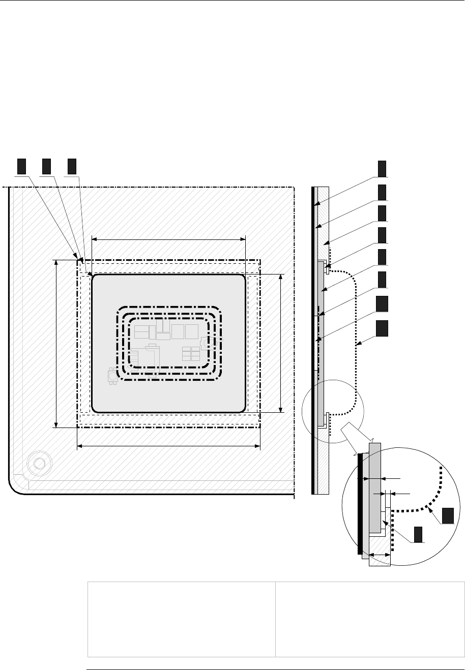
4.1 Minimum XE 020/ANT antenna module clearance
To guarantee the specified antenna range the following minimum clearance
between antenna and base material (aluminium) must be respected.
50
4
5
6
7
8
9
10
45
59
55
11
21 3 4
5
6
7
8
9
10
11
1,7
6
3,3
7
11
7
11
1, 8..XE 020/ANT antenna module
2, 7..Adhesive strip between antenna module
and front plate
3.......Front plate cutout
4........Front foil
5........Spacer foil
6........Front plate (aluminium)
7........refer to 2)
8........refer to 1)
9........Antenna
10......Insertable strip
11......Cover
Minimum clearance for the integrated RFID module

Assembly and installation notes XE 020
Suitable precautions must be taken to prevent any cables located behind
the antenna from causing antenna detuning, e.g. providing a cover.

RFID-Module Connections and wiring
5 Connections and wiring
5.1 EMC and wiring guidelines
5.1.1 Personal safety
Safety extra-low voltage
All operating panels are powered by safety extra-low voltage.
5.1.2 Why EMC-aware wiring?
The immunity of an electrical system depends essentially on wiring and
shielding that is designed to overcome any EMC problems. Servicing
experience has shown that inadequate wiring and shielding is a common
cause of system interference and failure.
Electromagnetic interference is far more troublesome than "conventional"
faults:
l It is not normally recognised as such from the symptoms displayed and
can often be mistaken for a fault in an assembly, which is basically
sound.
l They mainly occur sporadically and are difficult to duplicate.
As a consequence fault-finding is time-consuming and expensive.
Therefore ensure from the start that the wiring and shielding
conforms to the guidelines documented below.
5.1.3 Which EMC measures must be taken?
The EMC measures for the RFID module concentrate on shielding the
coaxial and connecting cable of the RFID module <-> OP 3xx.
5.2 Power supply
The power to the RFID module is supplied via the operating panel (refer to
chapter “XE 020/A module RJ45 socket“).
Connections and wiring XE 020
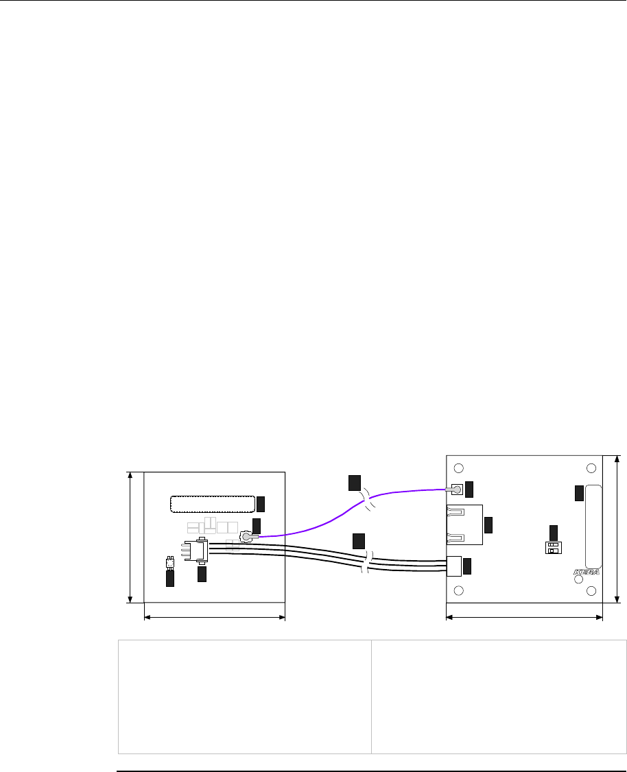
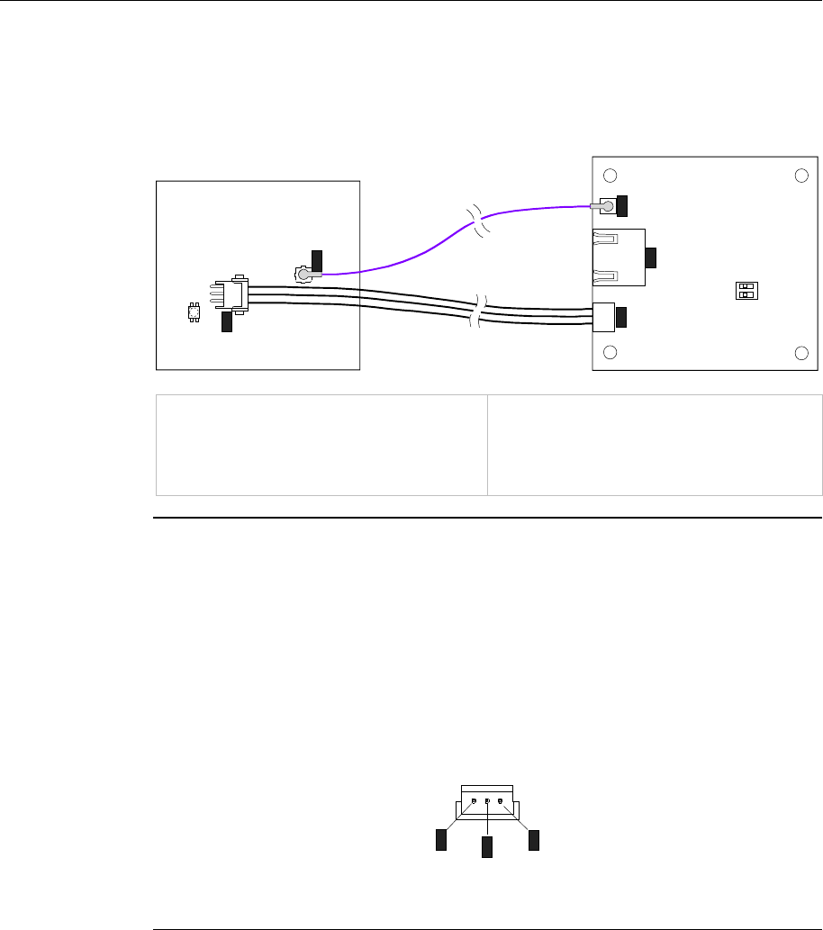
5.3 XE 020/A and XE 020/ANT module interfaces
N1
O N
1 2
XE 020 ANT
XE 020/A
1
2
3
4
5
XE 020/ANT antenna module
1.......Connector for coaxial antenna cable
2.......Connector for LED cable
XE 020/A RFID module
3........Connector for coaxial antenna cable
4........RJ45 socket for shielded connection cable
(max. 1 m) between RFID module and OP
3xx
5........Connector for LED cable
RFID module interface locations
5.3.1 Connector for coaxial antenna cable (1 and 3)
The XE 020 ANT antenna module and the XE 020/A RFID module both
have connectors for the coaxial antenna cable.
5.3.2 Connector for status LED (2 and 5)
The pin assignment is defined for the status LED connector as follows:
12
3
123
1...LED red
2...GND
3...LED green
Status LED connector on the XE 020/A and XE 020/ANT module: pin assignment
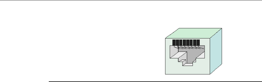
5.3.3 XE 020/A module RJ45 socket (4)
The RJ45 socket on the XE 020/A module is the counterpart to the "EXT0
external interface" on the operating panel. The interface comprises the
serial signals and the power for the XE 020/A module supplied by the
operating panel.
RFID-Module Connections and wiring
1…n.c.
2…n.c.
3…n.c.
4…Data-
5…Data+
6…n.c.
7…+12V
8… GND
21 3 4 5 6 7 8
RJ45 socket on the XE 020/A module: pin assignment
Plug specification
Refer to the KEBA manual, "RJ45 cable connections, General Guidelines".

Connections and wiring XE 020
5.4 Cables
5.4.1 Coaxial antenna cable
The maximum permitted length of the coaxial antenna cable is 300 mm.
5.4.2 Connector cable for RFID status LED
Three unshielded cores are sufficient for the RFID status LED connection
cable.
5.4.3 Connector cable for RFID module / OP 3xx
The connection cable for the RFID module / OP 3xx must be shielded and
no longer than 1 m.
RFID-Module Configuration
6 Configuration
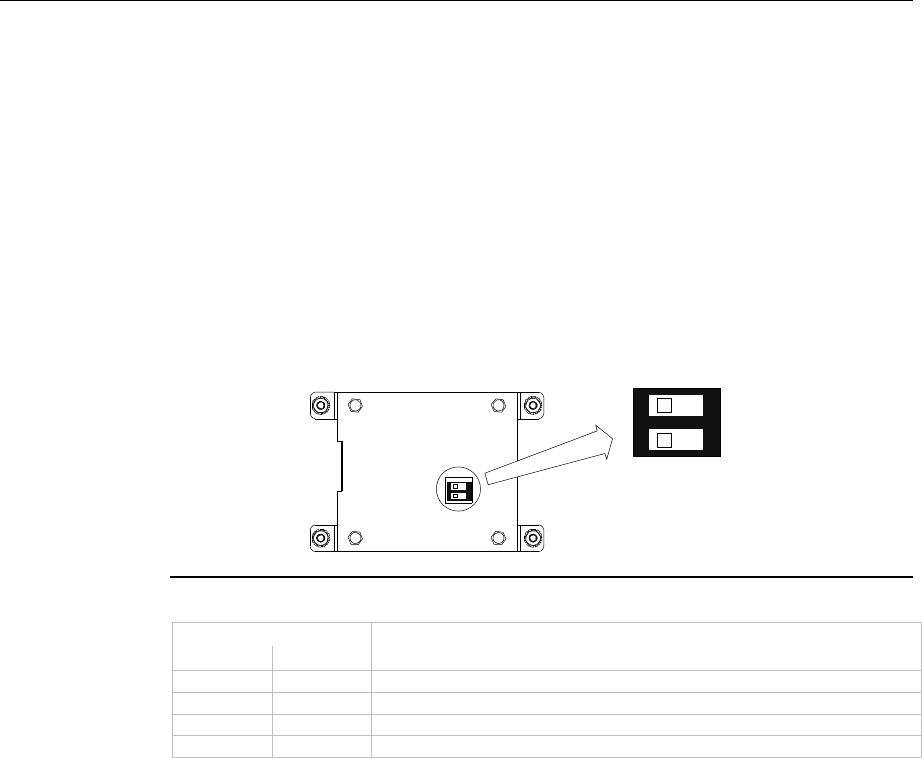
6.1 RFID module DIP switch
If the overall system contains multiple RFID modules, the HW addressing
must be configured using the DIP switch.
The required DIP switch is located directly on the RFID module. A
maximum of 4 addresses can be configured (factory setting: 14H):
O N
1 2
O N
1 2
ANT LED
RFID
Adr0
Adr1
DIP switch location and factory setting
DIP switch
Adr0 Adr1 Address
0 0 17H
0 1 16H
1 0 15H
1 1 14H

Status display XE 020
7 Status display
7.1 RFID status LED
The RFID status LED is located on the front of the operating panel and
indicates the status of RFID card recognition:
RFID status LED Meaning Cause of fault / solution
red RFID card not recognised or no
authorisation
l RFID card is defective
l Wrong information recorded
on RFID card
green for ca. 3
sec. RFID card has been recognised -
permanent red No firmware, hardware does not
boot l Contact the manufacturer
permanent
orange Not connected to the control l Check the wiring
LED off Connection is OK -
7.1.1 Boot-time behaviour
If a connection is established, the status LED is red for a short interval and
then becomes permanent orange. The firmware has failed to boot if the
LED does not change to the permanent orange state and indicates there is
a firmware fault. After connecting successfully the LED goes out.

RFID-Module Maintenance and repair notes
8 Maintenance and repair notes
8.1 Maintenance
This device does not require regular maintenance.
8.2 Repair
Only KEBA technicians may repair faulty devices, otherwise the warranty
becomes void.
8.2.1 Packaging and shipping
The module is placed in protective packing for shipping. Please return the
packaging since KEBA tries to reuse it to minimise the environmental
impact.
This protective packaging is not transport packaging and as such it is
unsuitable for transport by carrier or air. Suitable, extra transport packaging
must be used for this purpose.
8.3 Waste disposal
Comply with your national regulations for the disposal of electronic
components!

Accessories and spares XE 020
9 Accessories and spares
Component Order number
XE 020/A RFID module (evaluation unit) 70894
XE 020/ANT antenna module 71110
Coaxial antenna cable 300 mm 71352
Connector cable for RFID module / OP 3xx 58033
Connector cable for RFID status LED 73149
RFID card type RI-I02112A-03 -tba-

RFID-Module Technical specification
10 Technical specification
General
Reading distance: 4 cm from the front panel
Antenna installation: permanently installed in the front panel
Positioning of XE 020/A RFID module:
evaluation unit can be located up to 30 cm from
antenna
Communication protocol:
according to ISO 15693 or ISO 18000-3,
and suitable for Euromap 65
Evaluation unit protection class: IP 20
XE 020/A RFID module contact protection: metal case
XE 020/ANT antenna module contact protection: Plastic case
Signalling: 3-colour LED on the printed antenna
Interfaces
Data interface: serial
Supply voltage: 12 V DC (+/- 5%)
Connector plug: RJ45
RF signal
Frequency response: 13.56 MHz
Transmission power: 200 mW (max. 250 mW)
Sampling rate:
configurable (default: 10 samples / sec)
Dimensions Printed antenna width: 57 mm
length: 53 mm
Evaluation unit width: 88 mm (with casing)
length: 64 mm (with casing)
height: 21 mm (with casing)
Environmental conditions
Operating temperature: +5 °C to +55 °C
Storage temperature: -30 °C to +70 °C
Relative humidity: 5 to 95% (non-condensing)
Vibration resistance: as per IEC 61131
Shock resistance: as per IEC 61131

Relevant EC directives and applicable standards XE 020
11 Relevant EC directives and applicable standards
11.1 EC directives
99/5/EG R&TTE directive
11.2 Standards
The following non-legally binding European standards are used to validate
the RFID module's conformance to the directives.
11.2.1 Validating conformance to the R&TTE directive
Personal safety: EN 50364:2001
Radio sector: EN 300330-2 V1.3.1, Class 3 receiver
Class 1 as per 2000/299/EG
EMC sector: EN 301489-3 V1.4.1
Electrical safety: EN 60950-1:2001+A11:2004
11.2.2 Other standards
In addition the following non-legally binding standards provide advice in
some areas:
Environmental conditions
EN 61131-2:2003
Programmable logic controller - part 2 Equipment requirements and tests
11.2.3 USA standards
FCC Part 15 Radio Frequency Devices
The device complies with Part 15 of the FCC Rules. Operation in subject to
the following two conditions:
1. this device may not cause harmful interference, and
2. this device must accept any interference received, including in-
terference that may cause undesired operation.
This device is labelled with an FCC ID number.
If this label is not visible when installed in an end device, the outside of the
device MUST also display a label referring to the enclosed module.
e.g.
"Contains FCC ID: U870001"
(KEBA Product XE020/A; XE020/B)
Information
- No other antennas except the one provided by KEBA shall be used.
- Changes or modifications not expressly approved by KEBA could void the
user's authority to operate the equipment.