KEBA 0002 RFID transceiver working at 13.56 MHz User Manual kemro userid bden
KEBA AG RFID transceiver working at 13.56 MHz kemro userid bden
KEBA >
user manual

© KEBA 2008
Specifications are subject to change due to further technical developments. Details presented may be subject to correction.
All rights reserved.
Document: version 1.01 / article no.: 1000731
Filename: kemro_userid_bden.doc, last saving on: 29. 4. 2008
A: KEBA AG, Gewerbepark Urfahr, A-4041 Linz Tel.: +43 732 7090-0, Fax: +43 732 7309-10,
E-Mail: keba@keba.com
D: KEBA GmbH Automation, Leonhard-Weiss-Strasse 40, D-73037 Göppingen, Tel.: +49 7161 9741-0,
Fax: +49 7161 9741-40, E-Mail: keba@keba.com
US: KEBA Corp., 100 West Big Beaver Road, Troy, MI 48084, US,Tel.: +1 248 526-0561, Fax: +1 248 526-0562,
E-Mail: usa@keba.com
CN: Beijing Austrian KEBA Science and Technology Development Ltd., Room B516, Nan Xin Cang Tower,
A22 Dong Si Shi Tiao, Dong Cheng District, Beijing, 100027, P.R. China,
Telefon: +86 10 6409-6592, Fax: +86 10 6409-6312, E-Mail: china@keba.com
www.keba.com

User Identification System History
User's Manual, Version: 1.01 3
© KEBA 2008
History
Version Date Changes to chapter Description Author
V1.00 100408 New meis
V1.01 290408 Various changes meis

History Kemro UserID classic / eco
4 User's Manual, Version: 1.01
© KEBA 2008

User Identification System Contents
User's Manual, Version: 1.01 5
© KEBA 2008
Contents
1 Introduction......................................................................................................................9
1.1 Purpose of the document.......................................................................................9
1.2 Target groups, pre-requirements ...........................................................................9
1.3 Intended use ........................................................................................................10
1.4 Notes on this document .......................................................................................10
1.4.1 Contents of document ..............................................................................10
1.4.2 Not contained in this document................................................................10
1.5 Documentation for further reading .......................................................................11
2 Safety notes ...................................................................................................................12
2.1 Representation.....................................................................................................12
2.2 General safety instructions...................................................................................13
2.3 Personnel safety instructions ...............................................................................14
2.4 Safety instructions for maintenance.....................................................................14
3 General product description.........................................................................................15
3.1 Versions ...............................................................................................................16
3.1.1 Kemro UserID classic.....................................................................17
3.1.2 Kemro UserID eco............................................................................18
3.2 View of modules...................................................................................................19
3.2.1 Stand-alone version .................................................................................19
3.2.2 Integrable version (OEM) .........................................................................20
3.3 Recommended transponder (RFID data carrier)..................................................22
3.4 Spare parts and accessories................................................................................23
3.4.1 Connection cable......................................................................................23
3.4.2 Data disc (transponders)..........................................................................23
3.4.3 Software ...................................................................................................23
4 Mounting and installation instructions........................................................................24
4.1 Stand-alone version .............................................................................................24
4.2 Integrable versions (OEM) ...................................................................................27
4.2.1 Antenna 1 - XE020_ANT-OEM (variants B-OEM and D-OEM)................28
4.2.2 Antenna 2 - X110_ANT-OEM (Versions A-OEM and C-OEM).................29
4.2.3 Evaluation unit without housing (versions A-OEM and B-OEM) ..............31
4.2.4 Evaluation unit with housing (versions C-OEM and D-OEM)...................32
5 Show, connections and wiring.....................................................................................33
5.1 Status LED...........................................................................................................33
5.2 Connections .........................................................................................................33
5.2.1 Kemro UserID classic (stand-alone) ................................................33
5.2.2 Kemro UserID classic C-OEM / D-OEM...........................................34
5.2.3 Kemro UserID eco (stand-alone) .......................................................34
5.2.4 Kemro UserID eco C-OEM / D-OEM..................................................36

Contents Kemro UserID classic / eco
6 User's Manual, Version: 1.01
© KEBA 2008
5.2.5 Kemro UserID classic / eco A-OEM and B-OEM........................... 36
5.2.6 Antenna 1 (XE020_ANT-OEM) ............................................................... 37
5.2.7 Antenna 2 (X110_ANT-OEM).................................................................. 37
5.3 Shield clamp........................................................................................................ 38
5.3.1 Attaching the shield clamp....................................................................... 38
5.4 Power supply....................................................................................................... 39
5.4.1 Kemro UserID classic...................................................................... 39
5.4.2 Kemro UserID eco............................................................................. 40
5.5 Serial interface RS-232 (Kemro UserID classic) ......................................... 40
5.5.1 Kemro UserID classic and Kemro UserID classic C/D-OEM .. 40
5.5.2 Kemro UserID classic A/B-OEM...................................................... 41
5.6 USB 2.0 interface (Kemro UserID eco)......................................................... 42
5.6.1 USB interface for Kemro UserID eco C-OEM / D-OEM .................... 42
5.6.2 USB interface for Kemro UserID eco A-OEM / B-OEM..................... 43
6 Installation..................................................................................................................... 44
6.1 Requirements for the target system .................................................................... 44
6.2 Installation with Microsoft Windows 2000/2003 Server/XP/XPemb/Vista........... 45
6.3 Installation with Microsoft Windows CE............................................................... 45
6.3.1 Integration into the Windows CE Image .................................................. 45
6.3.2 Later installation / installation outside the Windows CE image ............... 46
6.3.3 Module settings for the operation with Windows CE ............................... 47
7 Operating behavior....................................................................................................... 48
7.1 Start-up behavior................................................................................................. 48
7.2 Behavior in operation .......................................................................................... 49
7.2.1 Activation modes for status LED ............................................................. 51
7.2.2 Validity test .............................................................................................. 52
7.3 Range and detection ........................................................................................... 53
8 Demo application.......................................................................................................... 54
8.1 Start-up operation................................................................................................ 54
8.1.1 Prerequisites............................................................................................ 54
8.1.2 Start-up operation of system ................................................................... 55
8.2 Description of the function of the demo application............................................. 55
8.2.1 Application window.................................................................................. 55
8.2.2 Tab page Read/Write Binary Data........................................................... 57
8.2.3 Tab page Read/Write Euromap 65 Data ................................................. 59
8.2.4 Tab Settings ............................................................................................ 60
9 Function interface of device driver ............................................................................. 63
9.1 Data format.......................................................................................................... 63
9.1.1 Euromap 65 Standard ............................................................................. 63
9.1.2 Binary format ........................................................................................... 63
9.2 Data structure...................................................................................................... 63
9.2.1 Data structure TEuromapData................................................................. 64
9.2.2 Data structure TEuromapOEMData ........................................................ 66
9.2.3 Data structure TEuromapTime ................................................................ 66

User Identification System Contents
User's Manual, Version: 1.01 7
© KEBA 2008
9.2.4 Data structure TFactorySettings...............................................................66
9.2.5 Data structure TModuleSettings...............................................................67
9.2.6 Data structure TRfidDeviceName.............................................................67
9.2.7 Data structure TRfidUid............................................................................68
9.2.8 Data structure for Callback.......................................................................68
9.3 Enumeration types ...............................................................................................69
9.3.1 Call-up actions of the Event Callback.......................................................69
9.3.2 Operating state of the Status LED............................................................69
9.3.3 Color of the Status LED............................................................................69
9.4 Constants.............................................................................................................70
9.5 Functions..............................................................................................................71
9.5.1 Registration of an Event Callback ............................................................71
9.5.2 Read out list of currently connected Kemro UserID modules..............72
9.5.3 Opening a connection to a Kemro UserID module..............................72
9.5.4 Closing a connection to an opened Kemro UserID module.................72
9.5.5 Controlling the LED of the Kemro UserID module...............................73
9.5.6 Reading out current settings of the Kemro UserID module.................73
9.5.7 New settings for the Kemro UserID module ........................................74
9.5.8 Reading out the factory settings of the Kemro UserID module ...........74
9.5.9 Creating a list of currently recognized transponders................................74
9.5.10 Opening a connection to a specific transponder....................................75
9.5.11 Closing a connection to an opened transponder....................................75
9.5.12 Reading out data from a transponder.....................................................76
9.5.13 Writing data of a transponder.................................................................77
10 Diagnosis........................................................................................................................78
11 Maintenance and repair instructions...........................................................................79
11.1 Maintenance.........................................................................................................79
11.2 Repair...................................................................................................................79
11.2.1 Packaging, shipment..............................................................................79
12 Disposal..........................................................................................................................80
12.1 Disposal of the module.........................................................................................80
13 Technical data................................................................................................................81
13.1 Stand-alone versions ...........................................................................................82
13.2 OEM versions.......................................................................................................82
14 EC directives and standards ........................................................................................83
14.1 EC Directives .......................................................................................................83
14.2 Standards.............................................................................................................83
14.2.1 R & TTE .................................................................................................83
14.2.2 Other Standards and recommendations ................................................83
14.2.3 Environmental and surrounding conditions ............................................84
14.3 Standards for the American market .....................................................................84
14.3.1 UL test for industrial control equipment..................................................84
14.3.2 FCC........................................................................................................84

Contents Kemro UserID classic / eco
8 User's Manual, Version: 1.01
© KEBA 2008

User Identification System Introduction
User's Manual, Version: 1.01 9
© KEBA 2008
1 Introduction
1.1 Purpose of the document
This document describes the products Kemro UserID classic and
Kemro UserID eco.
This manual enables the user to operate the above-mentioned products
and integrate them into the existing control and visualization system.
1.2 Target groups, pre-requirements
This document is made for the following persons with adequate skill pre-
requirements:
Target group Knowledge and skills pre-requirements
Project engineer • Basic technical training (University of Applied Science/University
level or corresponding professional experience),
• Knowledge in:
• working mode of a PLC,
• safety instructions,
• the application.
Operator • Basic technical training (Vocational high school, engineer training
or corresponding professional experience).
• Knowledge in:
• safety instructions,
• working mode of machine or plant,
• principal functions of the application,
• system analysis and troubleshooting,
• setting options at the operating installations.
Service technician • Basic technical training (Vocational high school, engineer training
or corresponding professional experience).
• Knowledge in:
• working mode of a PLC,
• safety instructions,
• working mode of machine or plant,
• Diagnosis possibilities,
• systematic error analysis and rectification.
Information
To integrate the
Kemro UserID
into an existing system does not require
knowledge about RFID technology and the EUROMAP 65 standard. The
necessary information is provided in respective chapter.

Introduction Kemro UserID classic / eco
10 User's Manual, Version: 1.01
© KEBA 2008
1.3 Intended use
Kemro UserID is used in applications for user identification at industrial
plants and machines. The typical applications areas include injection mold-
ing machines, robots, presses, machine tools, machines / systems in the
foodstuffs/luxury foodstuffs and pharmacy industries and similar.
Kemro UserID was developed, manufactured, tested and documented in
accordance with the appropriate safety standards. Provided, therefore, that
the instructions and safety precautions relating to the intended use are pro-
perly observed, under normal circumstances the products do not represent
any danger to the health of personnel or a risk of damage to other property
or equipment.
Information
KEBA assumes no liability for damages resulting from non-observance of
safety instructions or improper use.
1.4 Notes on this document
This manual is part of the product. It must be retained over the whole life-
time and if necessary referred to subsequent owners or users of the prod-
uct.
1.4.1 Contents of document
z Description of the product and its function
z Installation guidelines (mounting, cabling)
z Description of operating behavior
z Description of an example application
z Description of function interface
z Technical data
1.4.2 Not contained in this document
z Description of the integration packages
Integration packages are collections of modules that assist with the in-
tegration of the Kemro UserID products into the visualization system
used on the customer side.
z Description of the Kemro.userID secure+ version

User Identification System Introduction
User's Manual, Version: 1.01 11
© KEBA 2008
1.5 Documentation for further reading
Doc.No. Description Target group
DE: 1000732
EN: 1000733 Kemro.userID secure+ User's manual • Project engineer
• Commissioner
• Service technician
User's manuals Kemro.userID Integration
package
• Project engineer
• Commissioner
Safety notes Kemro UserID classic / eco
12 User's Manual, Version: 1.01
© KEBA 2008
2 Safety notes
2.1 Representation
At various points in this manual you will see notes and precautionary warn-
ings regarding possible hazards. The symbols used have the following
meaning:
!
DANGER!
• indicates an imminently hazardous situation which, if not avoided, will
result in death or serious injury.
!
WARNING!
• indicates a potentially hazardous situation which, if not avoided, could
result in death or serious injury.
!
CAUTION!
• means that if the corresponding safety measures are not taken a poten-
tially hazardous situation can occur which, if not avoided, may result in
property damage or slight bodily injury.
NOTICE
• NOTICE used without the safety alert symbol indicates a potentially
hazardous situation which, if not avoided, may result in property dam-
age.
• This symbol reminds you of the possible consequences of touching
electrostatically sensitive components.
Information
Information on use of equipment and useful practical tips is identified by the
symbol "Information". "Information" items do not contain any information
that draws attention to potentially dangerous or harmful functions.
User Identification System Safety notes
User's Manual, Version: 1.01 13
© KEBA 2008
2.2 General safety instructions
!
WARNING!
• The following application areas are expressly excluded for Kemro
UserID:
• Use in explosive or fire-risk areas
• Use in mining
• Outdoor use
• Kemro UserID are not allowed to be used for safety-relevant applica-
tions or safety functions (e.g. shutdown in emergency).
Other products are to be used for the above applications!
For further information, see EN 954-1 (EN ISO 13849-1).
!
CAUTION!
• Arbitrary or unsanctioned modifications to the device are prohibited.
This leads to the expiration of the conformity with the legal regulations
as well as loss of guarantee and warranty claims.
NOTICE
• Kemro UserID corresponds partially or completely to an "open type
equipment" (according to UL 508), depending on version, and must the-
refore be installed in a control cabinet or suitable housing.
Further information: See chapter Fehler! Verweisquelle konnte nicht ge-
funden werden..
• When removed from the rack, the integrable versions (OEM) are sensi-
tive to electrostatic discharge. Before handling the module, touch a
grounded metal object in order to discharge any static electricity from
your body.
Safety notes Kemro UserID classic / eco
14 User's Manual, Version: 1.01
© KEBA 2008
2.3 Personnel safety instructions
!
WARNING!
Danger of personal injury due to electric shock!
• Supply the Kemro UserID exclusively from power sources that have
a protective low voltage (e.g. SELV according to EN 60950-1)
• Connect only voltages and power circuits to connections, terminals
and interfaces up to 50 V rated voltage that have a secure disconnect
for hazardous voltages (e.g. with sufficient isolation).
!
CAUTION!
Fire hazard with module failure!
• Provide suitable fuses for the 24 V DC power supply of the final appli-
cation.
The maximum allowable fuse is 10 A!
2.4 Safety instructions for maintenance
!
CAUTION!
• Always turn off the power supply before mounting and dismounting the
Kemro UserID. Otherwise, the module can be destroyed or undefined
signal states can lead to damage of the control system.
!
CAUTION!
• The device may only be opened by qualified personnel and only main-
tenance activities expressly approved by KEBA may be performed (see
chapter “Service notes”).
• Protective measures against electrostatic discharge must be used (elec-
trostatic wristband, service mat) when performing maintenance and
service work.
• Do not touch the parts on the modules unless it is unavoidable.
• Turn off the power supply on the device before inserting or removing
the modules.

User Identification System General product description
User's Manual, Version: 1.01 15
© KEBA 2008
3 General product description
Kemro UserID is a system for easy and fast identification of users of in-
dustrial plants and machines. Process-related and frequent login and logoff
operations can be carried out reliably and efficiently.
User data stored on a card are transferred via non-contact RFID technology
to the control system of the plant or machine. The entry of passwords is no
longer necessary with Kemro UserID. This substantially increases the
security and transparency of the machines and plants.
Kemro UserID is available in different versions (see chapter V) and can
therefore be used for variety of applications.
Next to the hardware components, Kemro UserID also contains device
drivers for different operating systems. The device drivers have interfaces
that are easy to use for integration with all common visualization systems.
A pre-fabricated set of commands is available for user identification to facili-
tate the integration into a system.
In addition to the device drivers, comprehensive integration packages are
available for various, commercially available visualization systems. These
integration packages contain custom-made components for the simple in-
tegration of the Kemro UserID modules in the various visualization sys-
tems and present their versatile application options in an array of descrip-
tive application examples.
Details: See manuals for Kemro UserID integration packages

General product description Kemro UserID classic / eco
16 User's Manual, Version: 1.01
© KEBA 2008
3.1 Versions
The product versions are basically divided into the following two groups:
z "Stand-alone" versions:
All Kemro UserID stand-alone products are installed well protected in
rugged and compact housings. Their integration is simple and just as
problem-free with regard to retrofitting existing machines.
z Integrable versions (OEM):
For integrable Kemro UserID products, the installation is made di-
rectly in the customer's system, without interfering edges or gaps, which
effectively reduces contamination of the devices. The antenna for this is
integrated directly in the housing of the machine or the visualization de-
vice.
All OEM versions are available with different antennae and with or with-
out metal housing.
The Kemro UserID product line consists of the following versions:
Stand-alone version Integrable version
Kemro UserID classic
• Serial interface
• Module and antenna in a common
housing
• Rugged housing
(Front side: IP65)
Kemro UserID classic OEM
• Serial interface
• For installation in machinery and
plants
• Antennas can be remotely positioned
from the module
Kemro UserID eco
• USB interface
• Module and antenna in a common
housing
• Rugged housing
(Front side: IP65)
Kemro UserID eco OEM
• USB interface
• For installation in a machinery and
plants
• Antennas can be remotely positioned
from the module
Information
A further system version is
Kemro UserID secure+
. This additionally
offers a special encoding feature for increasing data security. This version
is not described in this manual due to the technical differences (see chapter
Documentation for further reading).

User Identification System General product description
User's Manual, Version: 1.01 17
© KEBA 2008
3.1.1 Kemro UserID classic
Material No. Name Description
074223 Kemro UserID
classic
(IC 140/A)
RFID read/write unit
• Stand-alone version with complete
electronics in compact plastic housing
• Serial interface
• Connector plug: 9 pole D-SUB (fe-
male) and 2 pole male connector
(supply)
• without connection cable
074224 Kemro UserID
classic A-OEM
(IC 140/A-OEM)
RFID read/write unit
• without sheet metal housing for evalu-
ation unit
• Serial interface
• Antenna 2 (L x W = 50 mm x 30 mm)
• Connecting plug: Terminal block
• without connection cable
• Shield clamp for the shield connection
(with fixing screw)
• Connection cable evaluation unit –
Antenna (coax cable and LED con-
nection cable)
074225 Kemro UserID
classic B-OEM
(IC 140/B-OEM)
RFID read/write unit
• without sheet metal housing for evalu-
ation unit
• Serial interface
• Antenna 1 (L x W = 57 mm x 53 mm)
• Connecting plug: Terminal block
• without connection cable
• Shield clamp for the shield connection
(with fixing screw)
• Connection cable evaluation unit –
Antenna (coax cable and LED con-
nection cable)
074226 Kemro UserID
classic C-OEM
(IC 140/C-OEM)
RFID read/write unit
• incl. sheet metal housing for evalua-
tion unit
• Serial interface
• Antenna 2 (L x W = 50 mm x 30 mm)
• Connecting plug: 9 pole D-SUB (fe-
male) and 2 pole male connector
(supply)
• without connection cable
• Connection cable evaluation unit –
Antenna (coax cable and LED con-
nection cable)

General product description Kemro UserID classic / eco
18 User's Manual, Version: 1.01
© KEBA 2008
Material No. Name Description
074227 Kemro UserID
classic D-OEM
(IC 140/D-OEM)
RFID read/write unit
• incl. sheet metal housing for evalua-
tion unit
• Serial interface
• Antenna 1 (L x W = 57 mm x 53 mm)
• Connecting plug: 9 pole D-SUB (fe-
male) and 2 pole male connector
(supply)
• without connection cable
• Connection cable evaluation unit –
Antenna (coax cable and LED con-
nection cable)
3.1.2 Kemro UserID eco
Material No. Name Description
074229 Kemro UserID eco
(IE 160/A )
RFID read/write unit
• USB interface
• Stand-alone version with complete
electronics in compact plastic housing
• Connecting plug: USB Type B
• without connection cable
074230 Kemro UserID eco
A-OEM
(IE 160/A-OEM)
RFID read/write unit
• USB interface
• Antenna 2 (L x W = 50 mm x 30 mm)
• Connecting plug: Terminal block
• without sheet metal housing for evalu-
ation unit
• without connection cable
• Connection cable evaluation unit –
Antenna (coax cable and LED con-
nection cable)
074231 Kemro UserID eco
B-OEM
(IE 160/B-OEM)
RFID read/write unit
• USB interface
• Antenna 1 (L x W = 57 mm x 53 mm)
• Connecting plug: Terminal block
• without sheet metal housing for evalu-
ation unit
• without connection cable
• Connection cable evaluation unit –
Antenna (coax cable and LED con-
nection cable)
User Identification System General product description
User's Manual, Version: 1.01 19
© KEBA 2008
Material No. Name Description
074232 Kemro UserID eco
C-OEM
(IE 160/C-OEM)
RFID read/write unit
• USB interface
• Antenna 2 (L x W = 50 mm x 30 mm)
• Connecting plug: USB Type B
• incl. sheet metal housing for evalua-
tion unit
• without connection cable
• Connection cable evaluation unit –
Antenna (coax cable and LED con-
nection cable)
074233 Kemro UserID eco
D-OEM
(IE 160/D-OEM )
RFID read/write unit
• USB interface
• Antenna 1 (L x W = 57 mm x 53 mm)
• Connecting plug: USB Type B
• incl. sheet metal housing for evalua-
tion unit
• without connection cable
• Connection cable evaluation unit –
Antenna (coax cable and LED con-
nection cable)
3.2 View of modules
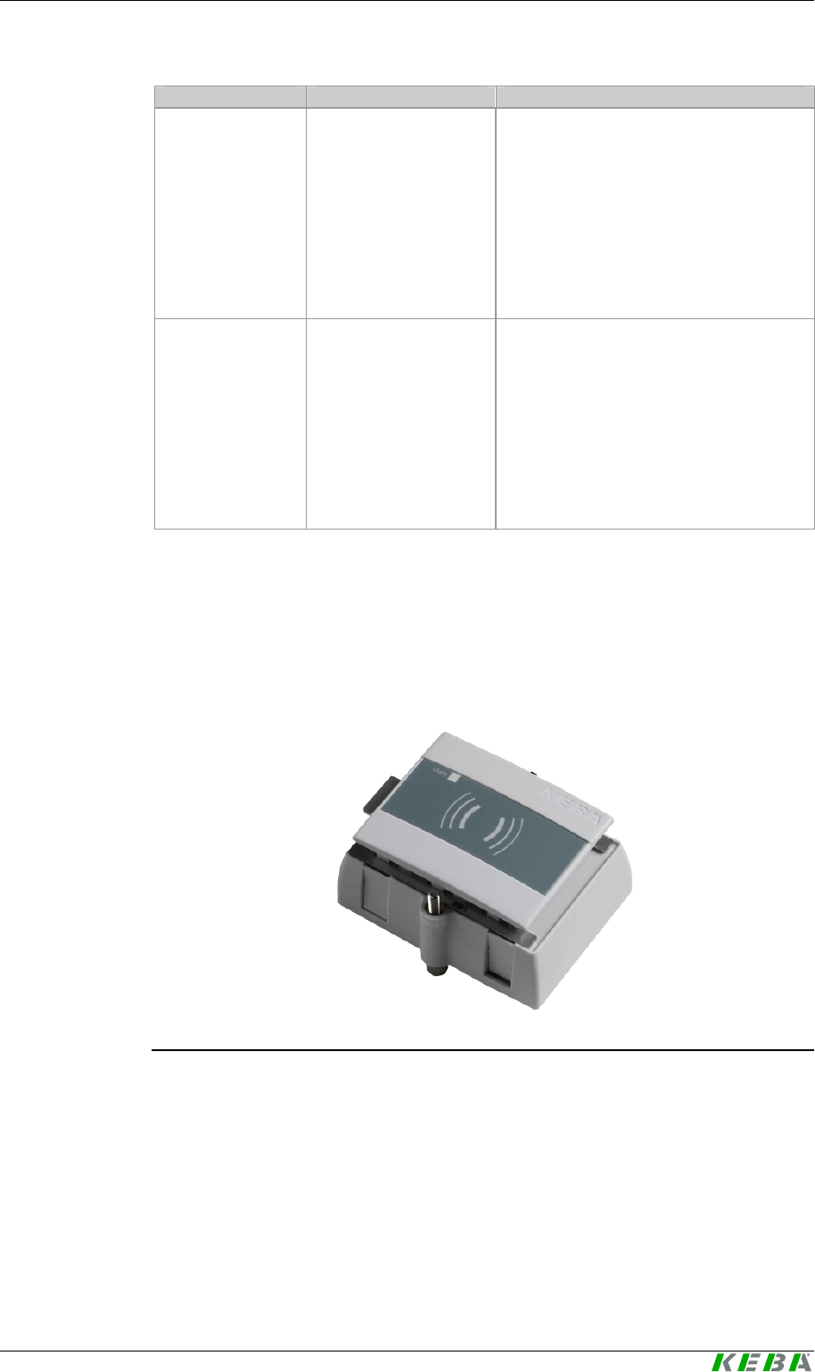
3.2.1 Stand-alone version
Stand-alone version (Kemro UserID classic / eco)
General product description Kemro UserID classic / eco
20 User's Manual, Version: 1.01
© KEBA 2008
3.2.2 Integrable version (OEM)
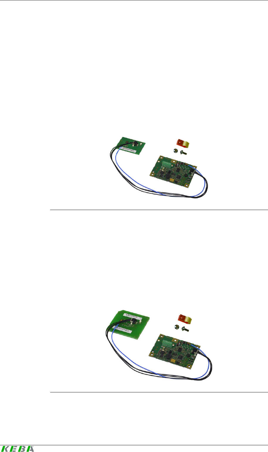
3.2.2.1 Kemro UserID classic / Kemro UserID eco A-OEM
Scope of delivery:
z Read/write unit without sheet metal housing for the evaluation unit
z Antenna 2 (L x W = 50 mm x 30 mm)
z Connecting cable evaluation unit -> antenna
z Shield clamp with fixing screw (shield connection)
Kemro UserID classic / Kemro UserID eco A-OEM
3.2.2.2 Kemro UserID classic / Kemro UserID eco B-OEM
Scope of delivery:
z Read/write unit without sheet metal housing for the evaluation unit
z Antenna 1 (L x W = 57 mm x 53 mm)
z Connecting cable evaluation unit -> antenna
z Shield clamp with fixing screw (shield connection)
Kemro UserID classic / Kemro UserID eco B-OEM
User Identification System General product description
User's Manual, Version: 1.01 21
© KEBA 2008
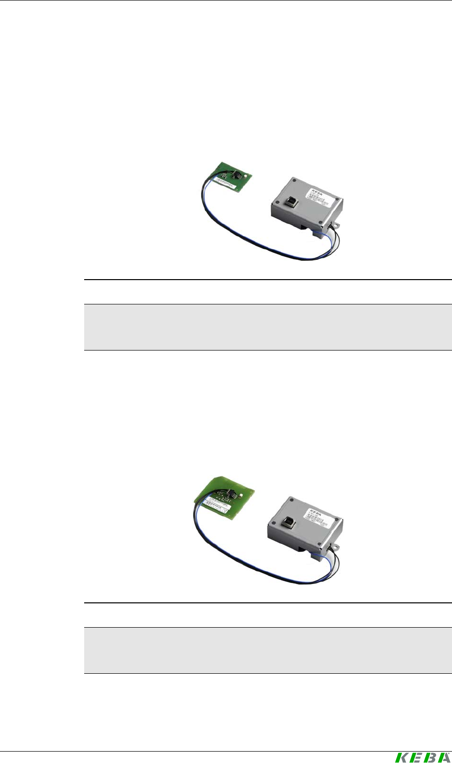
3.2.2.3 Kemro UserID classic / Kemro UserID eco C-OEM
Scope of delivery:
z Read/write unit with sheet metal housing for the evaluation unit
z Antenna 2 (L x W = 50 mm x 30 mm)
z Connecting cable evaluation unit -> antenna
Kemro UserID classic / Kemro UserID eco C-OEM
Information
The version
Kemro UserID classic OEM
only differs from the shown
Kemro UserID eco OEM
version by the different data interfaces.
3.2.2.4 Kemro UserID classic / Kemro UserID eco D-OEM
Scope of delivery:
z Read/write unit with sheet metal housing for the evaluation unit
z Antenna 1 (L x W = 57 mm x 53 mm)
z Connecting cable evaluation unit -> antenna
Kemro UserID classic / Kemro UserID eco D-OEM
Information
The version
Kemro UserID classic OEM
only differs from the shown
Kemro UserID eco OEM
version by the different data interfaces.

General product description Kemro UserID classic / eco
22 User's Manual, Version: 1.01
© KEBA 2008
3.3 Recommended transponder (RFID data carrier)
Kemro UserID classic or Kemro UserID eco is for use with
ISO/IEC 15693 compatible transponders (tags) designed with at least 256
bit freely writable memory.
Transponders with the following transponder chips are approved:
z Tag-it HF I Plus (Texas Instruments)
z Tag-it HF I Standard (Texas Instruments)
z I-Code SLI SL2 ICS20 (Philips)
Different transponder designs can be obtained directly from KEBA. The cor-
rect functioning of these transponders is guaranteed by KEBA through
comprehensive system tests. For an overview of all available transponders,
please see the chapter "Data disc (transponders)".
If other transponders are to be used, these are to be approved by KEBA.

User Identification System General product description
User's Manual, Version: 1.01 23
© KEBA 2008
3.4 Spare parts and accessories
3.4.1 Connection cable
Material No. Name Description
on request Serial data cable, 1 m D-Sub 9-pin plug/socket, 1 m
074212 Serial data cable, 3.6 m D-Sub 9-pin plug/socket, 3.6 m
on request Serial data cable, 5 m D-Sub 9-pin plug/socket, 5 m
073384 USB data cable,
USB type A/type B, 2 m USB-A-USB-B 2.0 m
070780 USB data cable,
USB type A/type B, 4 m USB-A-USB-B 4.0 m
069145 USB data cable,
USB type A/type B, 4.6 m USB-A-USB-B 4.6 m
Information
To ensure a proper functioning, we recommend using the cables specified
above.
3.4.2 Data disc (transponders)
Material No. Name Description
074665 XC140/A Check card transponder unprinted, 2kBit
on request XC140/Z Check card transponder, printed (4-color), 2
kBit
074662 XC240/A Key ring transponder unprinted, 2kBit
on request XC240/Z Key ring transponder, printed (4-color), 2 kBit
074710 XC340/A Wristband transponder unprinted, 2kBit
on request XC340/Z Wristband transponder, printed (4-color), 2
kBit
3.4.3 Software
Material No. Name Description
074345 Kemro UserID Device
driver CD-Rom
Device driver for the product line
Kemro UserID, suitable for instal-
lation in all Windows-based devel-
opment environments.
074346 Kemro UserID Integration
packages CD-ROM Kemro UserID Integration pack-
ages for the easy installation in
current visualization systems
Mounting and installation instructions Kemro UserID classic / eco
24 User's Manual, Version: 1.01
© KEBA 2008
4 Mounting and installation instructions
In order to guarantee the defined range of the antenna (see chapter
Technical data) and ensure an error-free operation, observe the installation
instructions listed in this chapter.
Information
The range is largely dependent on the installation situation.
(see chapter Range and detection)
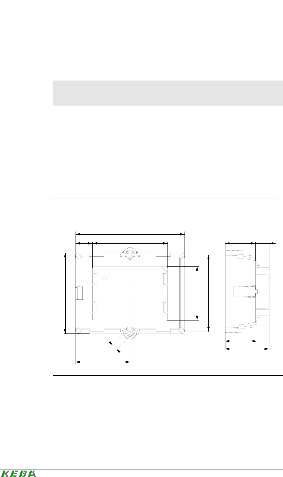
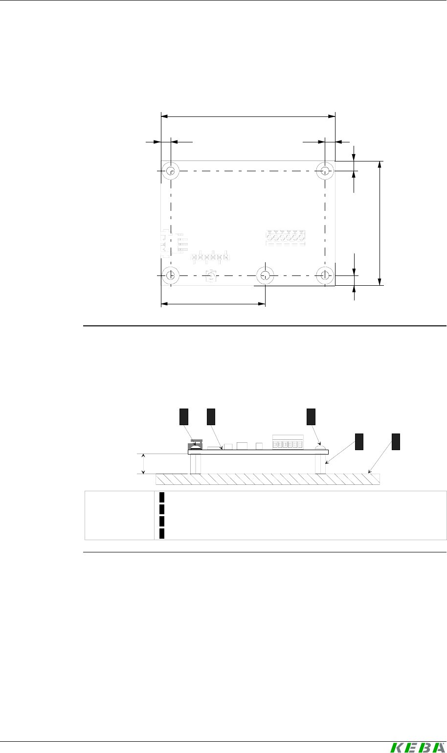
4.1 Stand-alone version
NOTICE
• The Kemro UserID stand-alone version is defined as "open type
equipment" (according to UL 508). After mounting the front side rates
as part of the final casing to a "type 1" indoor use (according to UL 508)
or the protection type IP65.
Dimensions:
25,1
34,6
24,1 10,5
77
38,5
12
57
38
54,4
4
53
Dimensions (in mm)
User Identification System Mounting and installation instructions
User's Manual, Version: 1.01 25
© KEBA 2008
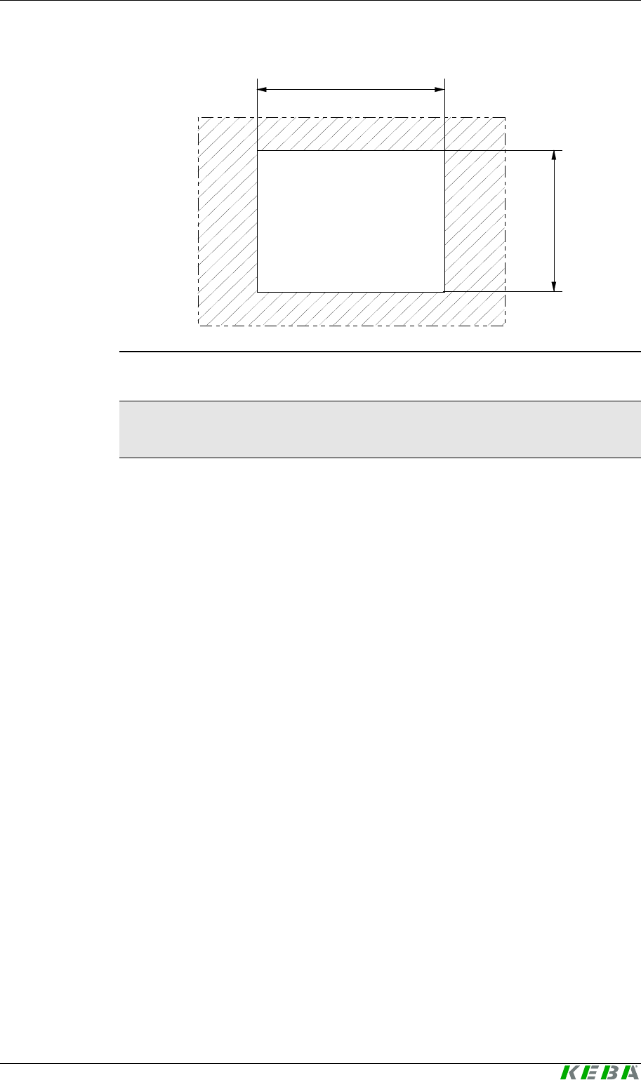
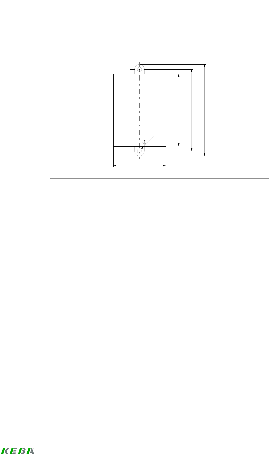
57
43
Cut-Out
Dimension of the opening for the installation (in mm)
Information
The edges of the opening must be deburred to prevent damage to the de-
vice that might occur otherwise.
Mounting and installation instructions Kemro UserID classic / eco
26 User's Manual, Version: 1.01
© KEBA 2008
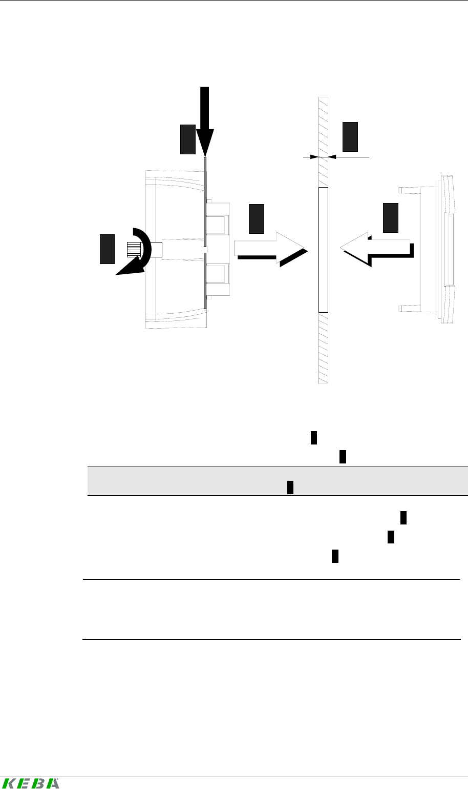
Installation
1
2
4
3
5
1. Create an opening with a size of 57 mm x 43 mm.
2. Remove the product from the packaging
3. Take off front cover (by pressing the clip 2 in the direction of the arrow)
4. Fit module (without front cover) in the opening 1.
Information
The wall strength of the carrier material 5 can amount to 1.5 mm and 6 mm.
5. Press in the clip of the mounting bracket and hold pressed 2
6. Stick the front cover onto the module from the front side 3.
7. Tighten both retaining screws (max. 0.5 Nm) 4.
NOTICE
• The housing can be damaged by tightening the retaining screws too
tightly.
User Identification System Mounting and installation instructions
User's Manual, Version: 1.01 27
© KEBA 2008
4.2 Integrable versions (OEM)
General installation instructions for all integrable versions:
z No metal may be located in front of the antenna print (from the perspec-
tive of the user).
z The larger the distance is between the antenna print and the metallic
environment, the greater the range.
z The back side of the antenna print and the evaluation electronics must
be protected against touching by a metallic cover.
The distance to the back side of the antenna print must be at least
2.5 cm.
• The module and the antenna are sensitive to electrostatic discharge and
thus corresponding ESD protection measures must be taken. (ground
strap)
NOTICE
• The operation of the module is only approved with the supplied anten-
nas. Arbitrary or unsanctioned modifications to the module or the an-
tenna are prohibited and will lead to the loss of the operating license.
NOTICE
• The Kemro UserID OEM-version is defined as "open type equipment"
(according to UL 508) so that it must be installed in a control cabinet or
in other suitable housings.
Information
• Not observing the installation instructions will result in a loss of guaran-
tee and warrantee claims.
• The manufacturer is responsible for the compliance with the corre-
sponding standards of the complete device for the integration of OEM
modules.
Mounting and installation instructions Kemro UserID classic / eco
28 User's Manual, Version: 1.01
© KEBA 2008
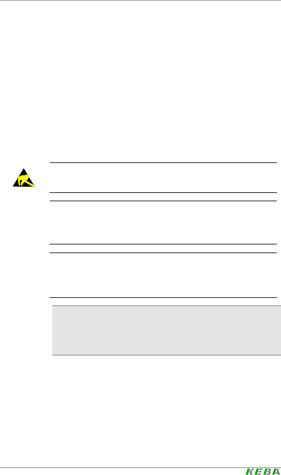
4.2.1 Antenna 1 - XE020_ANT-OEM (variants B-OEM and D-OEM)
57
53
6,5
6,5
10
3,3
Antenna 1 - XE020_ANT-OEM (dimensions in mm)
Information
The thickness of the circuit board varies over
±
10%, this must be reconsid-
ered for mounting the circuit board into the front plate. (see following figure)
4.2.1.1 Antenna 1: Installation example
5
6
7
8
9
21 3
4
5
2
1
6
7
7
2
7
min. 25 mm
depends on
circuit board
57
43
47
53
1 Antenna 1 (XE020_ANT-OEM)
antenna module
2 Adhesive strips between antenna
module and front plate
3 Opening in the front plate
4 Front film
5 Front plate (aluminum material)
at least 5 mm thick
6 Antenna
7 Metallic cover
Installation example of the antenna 1 (back view) (dimensions in mm)
User Identification System Mounting and installation instructions
User's Manual, Version: 1.01 29
© KEBA 2008
4.2.2 Antenna 2 - X110_ANT-OEM (Versions A-OEM and C-OEM)
12,93
2215,6
20,8
1,6
10
Antenna 2 - X110_ANT-OEM Antenna - dimensions (in mm)
Information
The thickness of the circuit board varies over
±
10%, this must be reconsid-
ered for mounting the circuit board into the front plate.
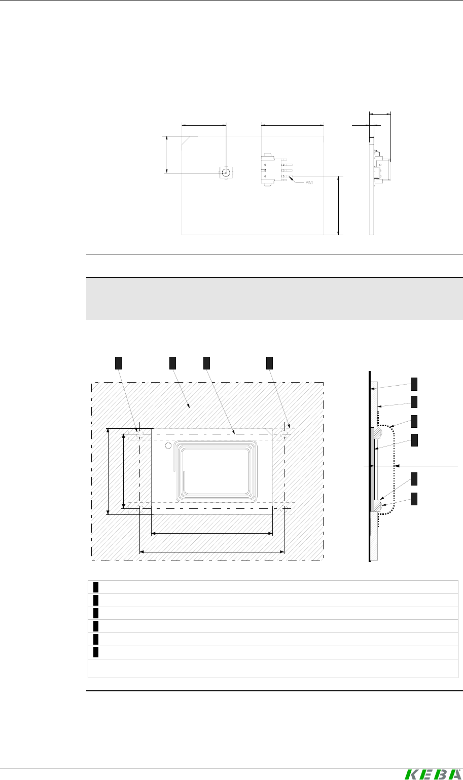
4.2.2.1 Antenna 2: Installation example
1
2
3
4
5
6
min. 25 mm
245
6
63
25
50
35
1 ... Front film (plastic)
2 ... Front plate
3 ... Metallic cover (contact protection)
4 ... Antenna 2 (X110_ANT-OEM) antenna module
5 ... Plastic clip *)
6 ... Screw
*) To prevent a restriction of the range, the support clip must never be made of a metallic material.
Installation example of the antenna 2 (back view) (dimensions in mm)

Mounting and installation instructions Kemro UserID classic / eco
30 User's Manual, Version: 1.01
© KEBA 2008
User Identification System Mounting and installation instructions
User's Manual, Version: 1.01 31
© KEBA 2008
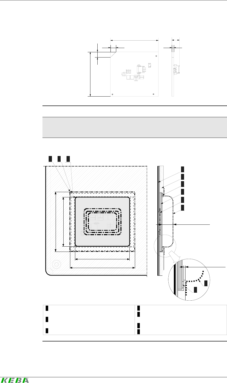
4.2.3 Evaluation unit without housing (versions A-OEM and B-OEM)
4 4
70
42
44
50
Dimensions of the evaluation unit without housing (versions A-OEM and B-OEM) (dimensions in mm)
4.2.3.1 Evaluation unit without housing - installation example
10
1 2
3 4
2
1 Evaluation unit (print)
2 Screw
3 Spacer bolts
4 Carrier material
Evaluation unit without housing - installation example
Mounting and installation instructions Kemro UserID classic / eco
32 User's Manual, Version: 1.01
© KEBA 2008
4.2.4 Evaluation unit with housing (versions C-OEM and D-OEM)
74
54
84
94
4,5
Dimensions of the evaluation unit with housing (versions C-OEM and D-OEM) (dimensions in mm)
4.2.4.1 Installation
The evaluation unit with housing can be screwed to any level carrier mate-
rial using 2 M4 screws.
User Identification System Show, connections and wiring
User's Manual, Version: 1.01 33
© KEBA 2008
5 Show, connections and wiring
5.1 Status LED
A three-color status LED to display the status is mounted on the housing
front of the stand-alone version or on the antenna module of the integrated
versions (OEM).
Information
The conditions of the status LED are described in chapter Diagnosis.
5.2 Connections
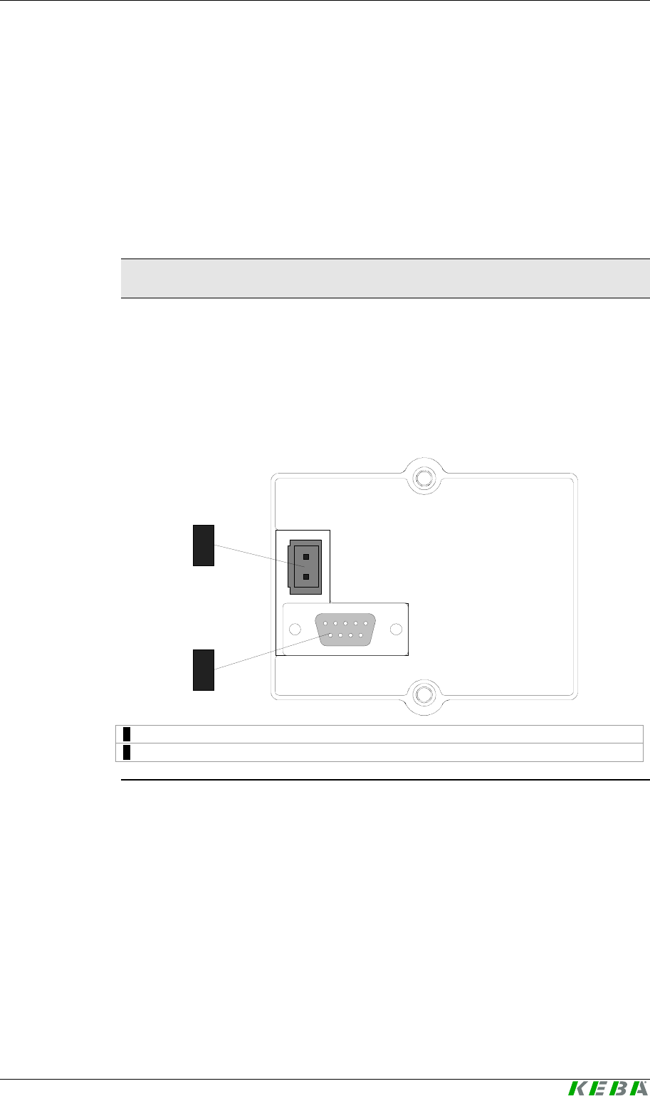
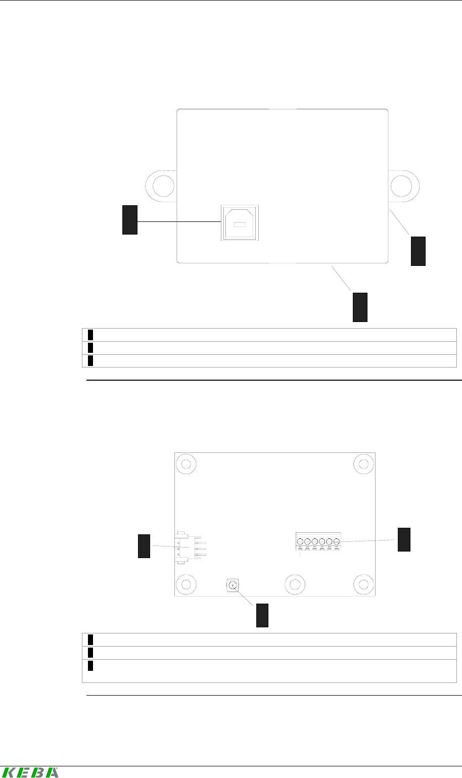
5.2.1 Kemro UserID classic (stand-alone)
24/12V
0V
RS232
1
2
1 … Voltage supply 24/12 V (2-pole plug)
2 … Serial interface (D-Sub socket 9-pole)
Kemro UserID classic, back view
Show, connections and wiring Kemro UserID classic / eco
34 User's Manual, Version: 1.01
© KEBA 2008
5.2.2 Kemro UserID classic C-OEM / D-OEM
24/12V
0V
RS232
ANT
LED
1
2
3
4
1 … Voltage supply 24/12 V (2-pole plug)
2 … Serial interface (D-Sub socket 9-pole)
3 … ANT, plug for antenna cable
4 … LED, plug for status LED
Kemro UserID classic C-OEM / D-OEM
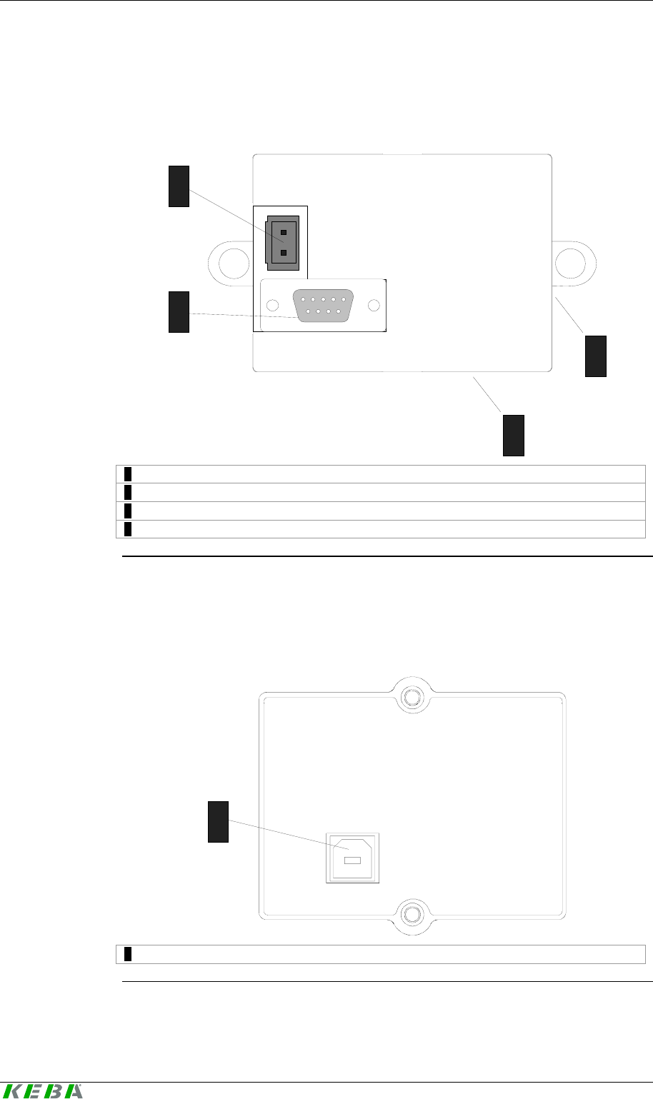
5.2.3 Kemro UserID eco (stand-alone)
USB
1
1 … USB interface (type B)
Kemro UserID eco, back view

User Identification System Show, connections and wiring
User's Manual, Version: 1.01 35
© KEBA 2008
Show, connections and wiring Kemro UserID classic / eco
36 User's Manual, Version: 1.01
© KEBA 2008
5.2.4 Kemro UserID eco C-OEM / D-OEM
USB
ANT
LED
1
2
3
1 … USB interface (type B)
2 … ANT, plug for antenna cable
3 … LED, plug for status LED
Kemro UserID eco C-OEM / D-OEM
5.2.5 Kemro UserID classic / eco A-OEM and B-OEM
1
13
2
1 … LED, plug for status LED
2 … ANT, plug for antenna cable
3 … S1, terminal block for data interface (eco and classic) and voltage supply
(classic only)
Kemro UserID classic / eco A-OEM and B-OEM
User Identification System Show, connections and wiring
User's Manual, Version: 1.01 37
© KEBA 2008
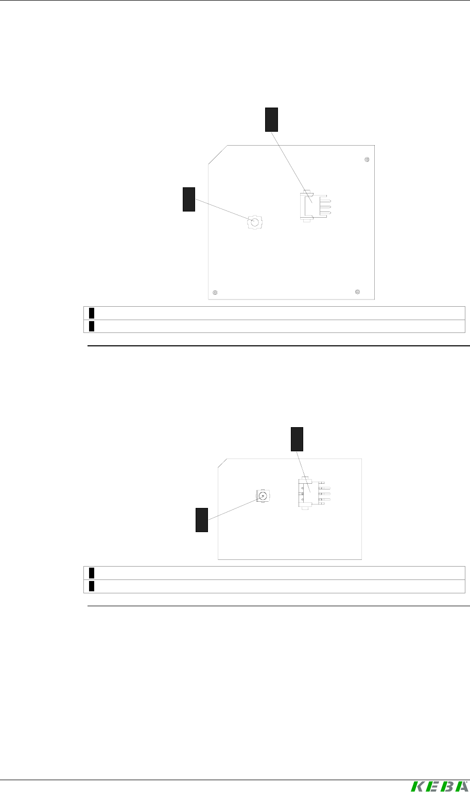
5.2.6 Antenna 1 (XE020_ANT-OEM)
1
2
1 … ANT … connection for antenna cable
2 … LED ... Connection for status LED cable
Antenna 1 (XE020_ANT-OEM)
5.2.7 Antenna 2 (X110_ANT-OEM)
1
2
1 … ANT, connection for antenna cable
2 … LED, connection for status LED cable
Antenna 2 (X110_ANT-OEM)
Show, connections and wiring Kemro UserID classic / eco
38 User's Manual, Version: 1.01
© KEBA 2008
5.3 Shield clamp
Information
The shield clamp is used for grounding and must never be used as strain
relief.
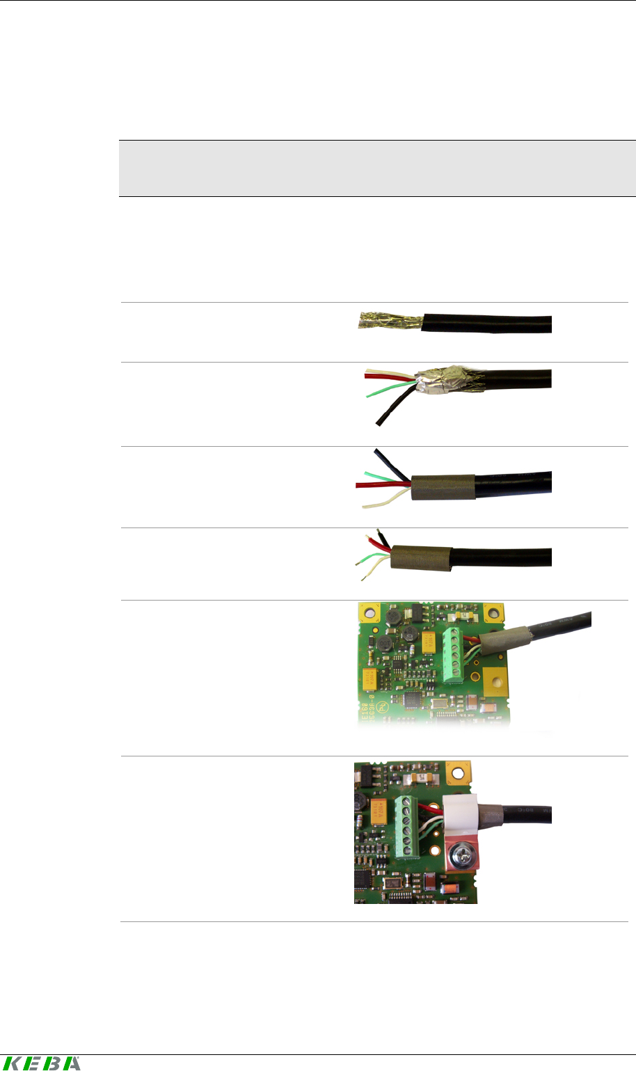
5.3.1 Attaching the shield clamp
Proceed as follows to connect the cable to the terminal block and subse-
quently attach the shield clamp:
1. Strip the insulation off the
cable end.
2. Fold back the shielding
braid and shielding foil.
3. Attach conductive textile-
backed strip.
4. Strip the insulation off the
pins.
5. Connect the pins to the ter-
minal block according to the
pin assignment.
6. Attach the shield clamp to
the print using fixing screw.
The cable is now connected and the shield clamp is connected with the
print.
User Identification System Show, connections and wiring
User's Manual, Version: 1.01 39
© KEBA 2008
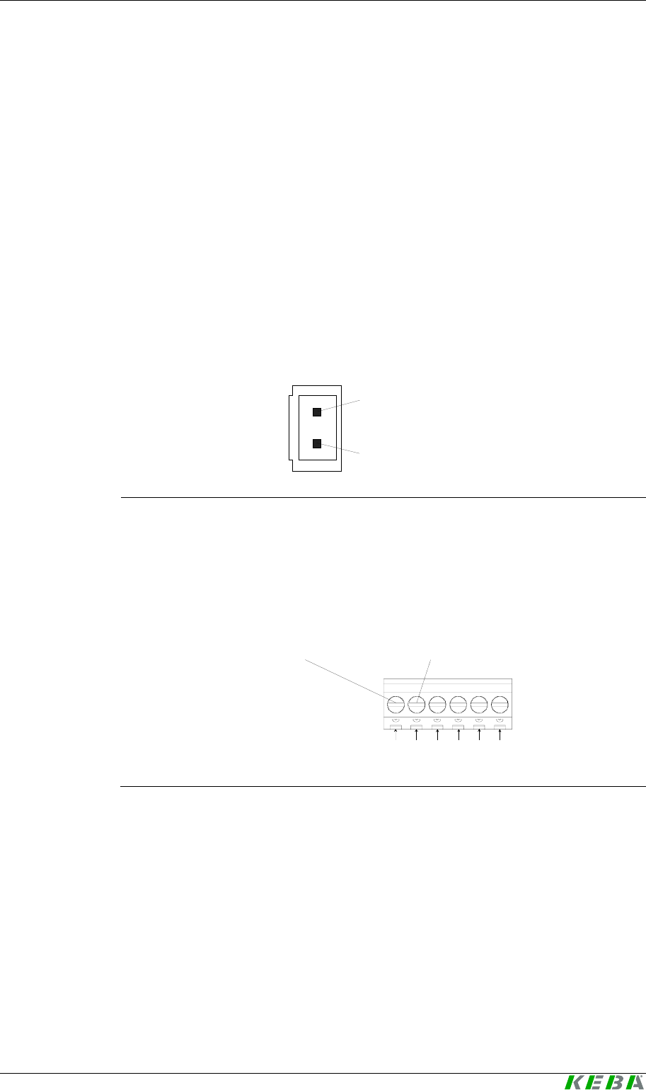
5.4 Power supply
5.4.1 Kemro UserID classic
All Kemro UserID classic modules can be optionally supplied with +24
V DC
or +12 V DC.
Depending on the module version, the voltage supply occurs either via a
plug or a terminal block.
Kemro UserID classic stand-alone, C-OEM / D-OEM:
24 / 12 V DC
0 V (GND)
Plug for the voltage supply (24/12V) for Kemro UserID classic stand-alone
C-OEM / D–OEM
Kemro UserID classic A-OEM / B-OEM:
16
24 / 12 V DC 0 V (GND)
Terminal block S1 for Kemro UserID classic A-OEM / B-OEM
Show, connections and wiring Kemro UserID classic / eco
40 User's Manual, Version: 1.01
© KEBA 2008
5.4.2 Kemro UserID eco
All Kemro UserID eco modules are supplied with voltage directly via the
USB interface.
Kemro UserID eco modules can only be connected to USB devices that
fulfill the high power standard, i.e. a voltage supply of 500 mA is guaran-
teed.
5.5 Serial interface RS-232 (Kemro UserID classic)
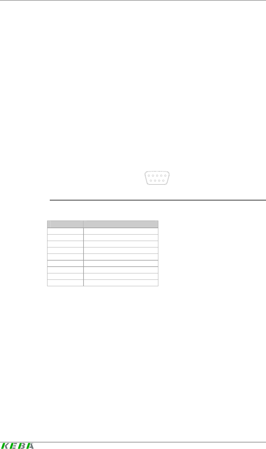
5.5.1 Kemro UserID classic and Kemro UserID classic C/D-OEM
51
96
9-pole DSUB female connector (S3)
Pin Description
1 --
2 RxD
3 TxD
4 --
5 0V (GND)
6 --
7 (RTS) is not used
8 (CTS) is not used
9 --
5.5.1.1 Cable and plug specification:
Cable type
Shielded standard cable.
Plug type
9-pole D-SUB male connector with completely conductive shell.
The cable shielding must be connected plane with the shield cover of the
plug.
User Identification System Show, connections and wiring
User's Manual, Version: 1.01 41
© KEBA 2008
Cable length
tested up to 30 m
Minimum bend radius
Minimum bend radius during installation: 60 mm
Minimum bend radius for installed cable: 50 mm
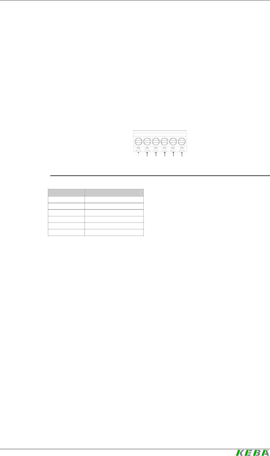
5.5.2 Kemro UserID classic A/B-OEM
16
Terminal block S1
Terminal Description
1 +24/12V
2 0V (GND)
3 CTS
4 RxD
5 TxD
6 RTS
5.5.2.1 Cable and plug specification:
Cable type
Shielded standard cable.
Cable length
tested up to 30 m
Minimum bend radius
Minimum bend radius during installation: 60 mm
Minimum bend radius for installed cable: 50 mm
Show, connections and wiring Kemro UserID classic / eco
42 User's Manual, Version: 1.01
© KEBA 2008
5.6 USB 2.0 interface (Kemro UserID eco)
Kemro UserID eco is a high-power USB device and has a standard
USB 2.0 interface. The USB master interface to which the Kemro UserID
eco - module is connected must be able to supply this with 500 mA (high-
power).
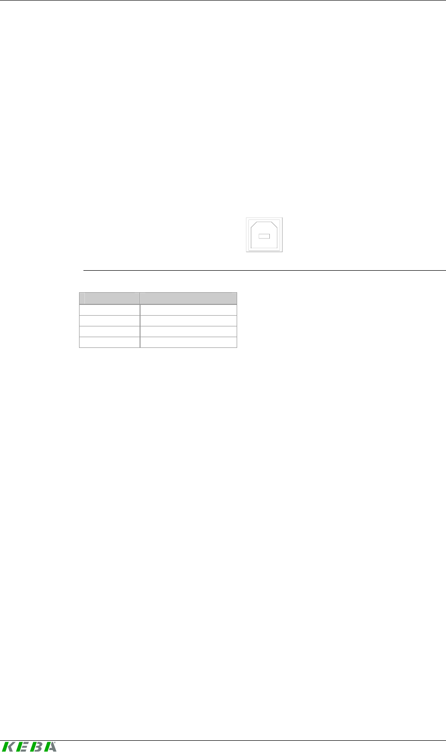
5.6.1 USB interface for Kemro UserID eco C-OEM / D-OEM
21
34
USB interface type B
Pin Description
1 Vbus (+5V)
2 D-
3 D+
4 0 V (GND)
5.6.1.1 Cable and plug specification:
Cable type
Shielded USB cable, twisted pair data cables with a characteristic imped-
ance of 90 Ohm +/- 15%.
Cable length
tested up to 5 m
User Identification System Show, connections and wiring
User's Manual, Version: 1.01 43
© KEBA 2008
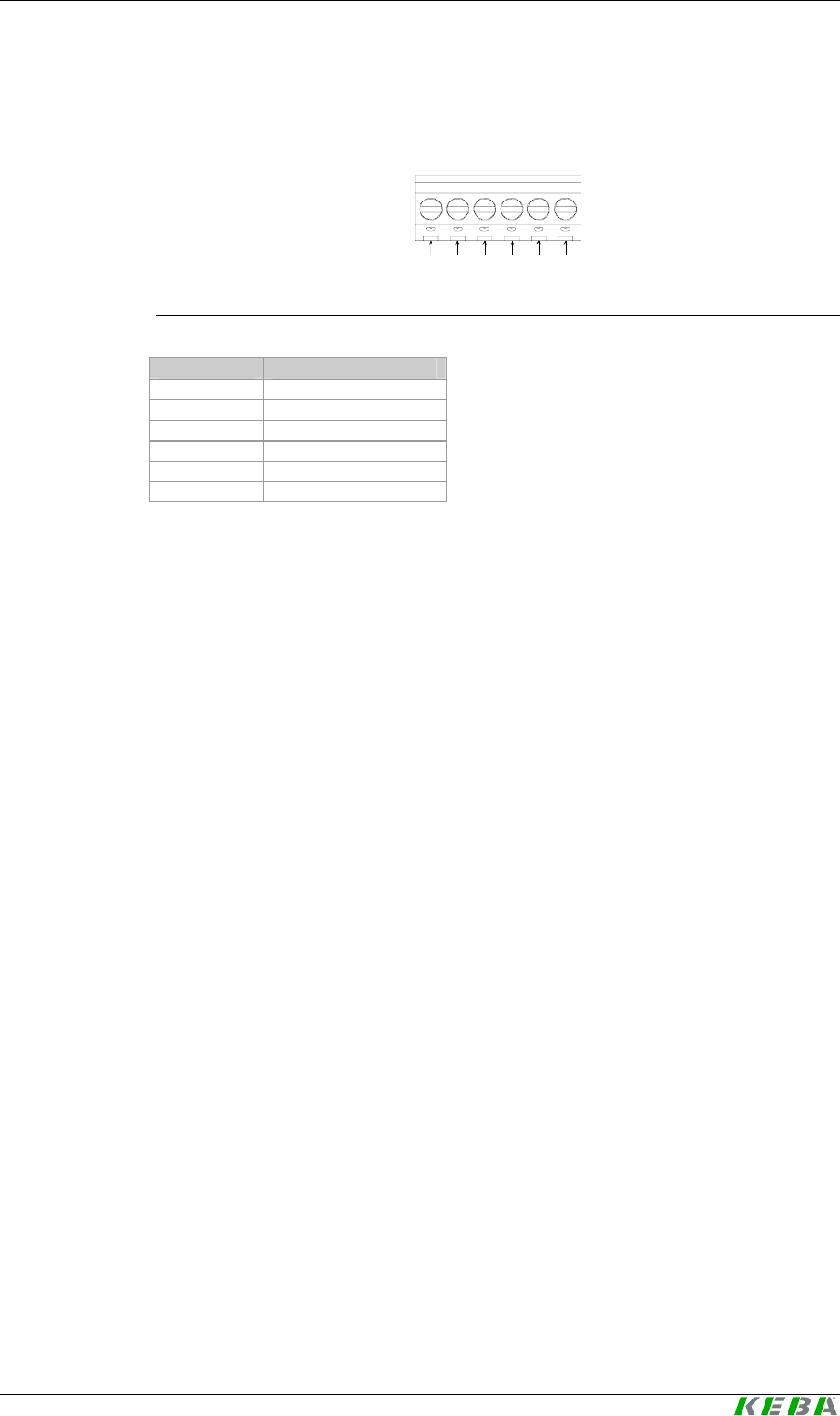
5.6.2 USB interface for Kemro UserID eco A-OEM / B-OEM
16
Terminal block S1
Terminal Description
1 0V (GND)
2 D+
3 D-
4 0V (GND)
5 0V (GND)
6 5V
5.6.2.1 Cable and plug specification:
Cable type
Shielded USB cable, twisted pair data cables with a characteristic imped-
ance of 90 Ohm +/- 15%.
Plug type
Standard USB connector type B with fully conductive shell.
The cable shielding must be connected plane with the shield cover of the
plug.
Cable length
tested up to 5 m

Installation Kemro UserID classic / eco
44 User's Manual, Version: 1.01
© KEBA 2008
6 Installation
Generally the Kemro UserID can be integrated with every system that,
depending on the product version, has a serial interface or USB interface
with a host function (master) and is supported by the operating system.
The device drivers supplied are suitable for the following operating sys-
tems:
z Microsoft Windows XP
z Microsoft Windows XP emb.
z Microsoft Windows CE 5.x
z Microsoft Windows Vista
z Microsoft Windows 2000
z Microsoft Windows Server 2003
When integrating serial Kemro UserID modules in systems conforming
to EN 61131, the following additional operating systems are possible:
z Linux
z VxWorks
6.1 Requirements for the target system
Before installing the Kemro UserID one of the following operating sys-
tems must have been fully installed in the target system:
z Microsoft Windows XP SP2
z Microsoft Windows XP emb.
z Microsoft Windows CE 5.x
z Microsoft Windows Vista
z Microsoft Windows 2000 SP4
z Microsoft Windows Server 2003
In case of product version Kemro UserID eco the following additional
requirement must be met:
z USB interface (host controller / master, type A socket, the interface
can supply high-power devices with 500 mA current consumption)

User Identification System Installation
User's Manual, Version: 1.01 45
© KEBA 2008
6.2 Installation with Microsoft Windows 2000/2003
Server/XP/XPemb/Vista
1.) Start target system.
2.) Insert Kemro UserID installation CD into the CD drive.
3.) Start installation by calling up the file
INSTALL_device_driver.cmd (directory <Kemro UserID
CD>\drivers\Win_XP_Vista).
4.) Re-start system.
The drivers necessary for operation are installed and Kemro UserID can
now be used from all windows-based application development systems.
6.3 Installation with Microsoft Windows CE
6.3.1 Integration into the Windows CE Image
1.) Start target system.
2.) Copy the files
SIUSBXP.dll
SIUSBXP_LIB.dll
UIDDRV_RfbCommUsb.dll
UIDDRV_RfbMaster.dll
UIDDRV_RfbInterface.dll
UIDDRV_RfidInterface.dll
UIDDRV_RfidService.dll
of directory <Kemro UserID CD>\drivers\win_ce into directory
\Windows of the target system.
3.) Take over the registry entries from files SIUSBXP.reg and
UIDDRV_Win32ce_RfidService.reg.
Here the Dll entries are to be set on \Windows\SIUSBXP.DLL or
\Windows\UIDDRV_RfidService.dll (in the platform builder).
4.) Create Windows CE Image in the platform builder.
The drivers necessary for operation are installed and Kemro UserID can
now be used from all windows-based application development systems.

Installation Kemro UserID classic / eco
46 User's Manual, Version: 1.01
© KEBA 2008
6.3.2 Later installation / installation outside the Windows CE image
1.) Start target system.
2.) Copy the files
SIUSBXP.dll
SIUSBXP_LIB.dll
UIDDRV_RfbCommUsb.dll
UIDDRV_RfbMaster.dll
UIDDRV_RfbInterface.dll
UIDDRV_RfidInterface.dll
UIDDRV_RfidService.dll
of directory <Kemro UserID CD>\drivers\win_ce into a non-
volatile directory (e.g. flash drive, a hard disc or a battery-buffered
Ram)
3.) Take over the registry entries of file
UIDDRV_Win32ce_RfidService.reg into the registry of the target
system and at the same time change the path of entry Dll to the
path under which file UIDDRV_RfidService.dll was stored
.
The registry can be edited via a remote registry editor if the target
system has no registry editor available. The suitability of the editor
depends on the Windows CE image and the CPU used. Additional in-
formation is available from the manufacturer of the target system.
4.) Now connect the Kemro UserID module to the target system. The
target system will now display a dialog in which you are requested to
enter the driver for the new device. Now specify the file
<pfad>\SIUSBXP.dl, which could not be copied into the non-
volatile directory of the target system.
If this dialog is not displayed the registry key
[HKEY_LOCAL_MACHINE\DRIVERS\USB\LoadClients\Default
\Default\255] is to be deleted in the target system with the aid of
the registry editor. The connecting cable to the Kemro UserID mo-
dule must then be unplugged and again plugged in. The dialog should
now be displayed.
5.) Re-start the target system.
The drivers necessary for operation are installed and Kemro UserID can
now be used from all windows-based application development systems.

User Identification System Installation
User's Manual, Version: 1.01 47
© KEBA 2008
6.3.3 Module settings for the operation with Windows CE
In order to keep the system capacity low with the use of the device driver,
we recommend setting the inventory cycle (cycle time with which the mod-
ule is polled by the driver via identified cards) to 300 ms (default value: 50
ms).
This setting can be carried out using the demo application (see chapter Tab
Settings). Moreover, the inventory cycle can also be set directly via the de-
vice driver (see chapter New settings for the Kemro UserID module).

Operating behavior Kemro UserID classic / eco
48 User's Manual, Version: 1.01
© KEBA 2008
7 Operating behavior
7.1 Start-up behavior
During the startup of the Kemro UserID module, states are displayed in
the following order by the status LED:
Step Display Description
1 off (continuous) Only for Kemro UserID eco:
Module from device driver not yet detected and swit-
ched on.
Only for Kemro UserID classic:
Once the module is supplied with voltage, the status
LED lights up red and the firmware is loaded (step 2)
2 red (continuous) Firmware is loaded
3 orange (continuous)
Firmware is loaded, data communication with device
driver on the host system is established
4 green / orange
(blinking) Supply and data communication with device driver on
the host system exists
After completion of the startup, the LED can either be set individually by the
driver or through a communication interface by the application (see chapter
Activation modes for status LED).
User Identification System Operating behavior
User's Manual, Version: 1.01 49
© KEBA 2008
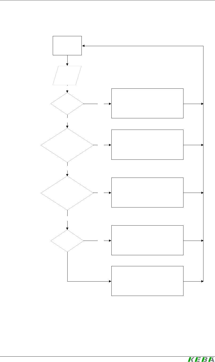
7.2 Behavior in operation
Module waits
for TAG
TAG
identified
TAG
readable?
Perform check for
Euromap 65
standard?
**)
Data exists in
Euromap 65
standard?
Data
valid?
YES
YES
YES
YES
NO
NO
NO
NO
State 5 "Not readable TAG found";
UID of the TAG will be sent to the
system -> further processing
via application
Status-LED blinks red *)
State 4 "New/blank TAG found";
-> further processing via application
Status-LED blinks green *)
State 4 "New/blank TAG found";
-> further processing via application
Status-LED blinks green *)
State 3 "Validation check failed";
-> further processing via application
Status-LED blinks green *)
State 2 "Valid TAG found";
-> further processing via application
Status-LED blinks green *)
*) This behavior of the Status-LED only occurs, if the control of the Status-LED will be performed by the
device driver (dwLedControlMode=0)
**) Whether the check for the Euromap65 Standard is performed or not, is configured via the configura-
tion entry boolCheckValidation.

Operating behavior Kemro UserID classic / eco
50 User's Manual, Version: 1.01
© KEBA 2008
Information
For a detailed description of the individual status messages, see the chap-
ter Call-up actions of the Event Callback.
The operating behavior of the started up Kemro UserID modules is de-
pendent on their configuration. Configurations in all Windows-based devel-
opment environments for the following parameters can be determined via a
predefined data structure (see chapter Data structure TModuleSettings):
z dwLedControlMode
This determines how the status LED is controlled after successful star-
tup.
z boolCheckValidation
This determines whether a validity test according to Euromap 65 guide-
line is to occur.
Via a function of the device driver from the Kemro UserID module, the
selected configuration can be read and also written to this (see chapter
Call-up actions of the Event Callback).

User Identification System Operating behavior
User's Manual, Version: 1.01 51
© KEBA 2008
7.2.1 Activation modes for status LED
Two operation types result by the setting of the parameter dwLedCon-
trolMode for the signaling of the Kemro UserID modules through the
status LED:
z Operation type 0 (status on delivery)
The device driver controls the status LED according to the schema
shown below. The read/write functions on the status LED from the ap-
plication remain without effect.
LED signals Designation / description
LED green (continuous) Default behavior if valid module detected
LED green (blinking, max. 3
sec.) Readable transponder detected
The status LED blinks green as long as the trans-
ponder is within reading range (max. 3 sec.)
LED red (blinking, max. 3 sec.) Transponder could not be read; unsupported trans-
ponder type
The status LED blinks red as long as the transponder
is within reading range (max. 3 sec.)
Information
The signaling via the status LED merely provides information about
whether a transponder was able to be read correctly. Whether the stored
used on the transponder can actually be logged in on the system is not sig-
naled in this operating mode.
z Operating mode 1
status LED is controlled by the application. In this was, the LED can be
arbitrarily set by the application via the corresponding read/write func-
tions. An individual formation of the acknowledgement can thus be real-
ized through the status LED.
Information
The data basis for the user data is stored in the control or visualization sys-
tem and is retrievable by the associated application. Thus, the validity of
user data can be checked in the application and signaled via driver inter-
face through the status LED of the
Kemro UserID
module.

Operating behavior Kemro UserID classic / eco
52 User's Manual, Version: 1.01
© KEBA 2008
7.2.2 Validity test
The setting of the parameter boolCheckValidation determines whether
the transponder is checked for validity according to the Euromap 65 guide-
line. Through this setting, different call actions of the callback function be-
come effective (see chapter Call-up actions of the Event Callback).
z TRUE (status on delivery)
Validity of a detected transponder is checked according to the Euromap
65 guideline. The data content is linked with an individually settable
"security key". Falsified transponders can thus be reliably detected.
Thus the following invoking actions of the callback function of the driver
are possible through the validity test:
z Valid transponder found
z Falsified transponder was found (security test failed)
z Empty / invalid transponder was found
z Unreadable transponder was found
z Known transponder was removed.
z FALSE
No validity test of a known transponder is performed. Thus, the follow-
ing invoking actions of the callback function of the driver are possible:
z Transponder was found
z Unreadable transponder was found
z Known transponder was removed.
Information
The invoking action "Transponder was found" for switched off validity test is
ident with the invoking action "Empty / invalid transponder was found" for
activated validity test.

User Identification System Operating behavior
User's Manual, Version: 1.01 53
© KEBA 2008
7.3 Range and detection
The range between transponder and the Kemro UserID module is de-
pendent on the installation situation, the antenna size (with OEM versions)
and the transponder used. The range increases if the antenna (for OEM
versions) or the stand-alone module are installed in non-metallic materials.
In addition, the range increases if a sufficiently large surface is available for
the transponder antenna. Thus, check card transponders have a slightly
higher range than transponders in the form of key chains.
The simultaneous detection of up to four transponders is possible. If multi-
ple transponders are in the reception area of a Kemro UserID module
simultaneously, the module will automatically attempt to read out the trans-
ponders, filter out unreadable transponders and make the valid card(s)
available at the interface of the device driver.

Demo application Kemro UserID classic / eco
54 User's Manual, Version: 1.01
© KEBA 2008
8 Demo application
The demo application is a complete application with which the Kemro
UserID can be put into operation quickly and easily on systems with Mi-
crosoft Windows.
The demo application is a practical application for reading out and writing
on transponders in Euromap 65 or binary form.
The demo application can be used to configure Kemro UserID modules
and to test different functions.
8.1 Start-up operation
8.1.1 Prerequisites
Before installing the demo application one of the following operating sys-
tems must have been fully installed in the target system:
z Windows XP
z Windows XP emb.
z Windows Vista
z Windows 2000
z Windows Server 2003
In case of product version Kemro UserID eco the following additional
requirement must be met:
z USB interface (host controller / master, type A socket, the interface
can supply high-power devices with 500 mA current consumption)

User Identification System Demo application
User's Manual, Version: 1.01 55
© KEBA 2008
8.1.2 Start-up operation of system
1.) Installation of the device driver. See chapter Installation with Microsoft
Windows 2000/2003
Server/XP/XPemb/Vista
2.) Installation of .NET Framework 2.0, if it is not already in the target
system. This setup can also be called up from the CD-ROM at:
<root>/drivers/Framework 2.0/dotnetfx.exe
3.) Connect the Kemro UserID modules with target system and en-
sure the power supply of the modules.
4.) Start the demo application. The demo application can only be started
directly from the CD-ROM and can be called up at: <root>/demo
application/Demo_Application.exe
8.2 Description of the function of the demo application
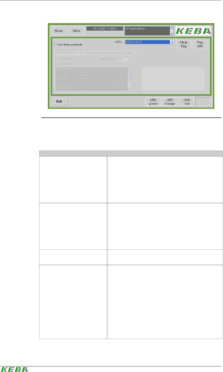
8.2.1 Application window
Description of the mask
The application window of the demo application consists of a continuously
visible (general) part and a part that can be switched over via tabs.
In the constantly visible part of the application the general functions of the
Kemro UserID modules are contained. On the tab pages of the applica-
tion files can be manipulated and module configurations displayed and
changed.
The Kemro UserID modules can read out and write on transponders in
Euromap 65 format or binary format. The write and read processes can be
switched over with the two tabs Read / Write Binary Data and Read / Wri-
te Euromap 65 Data.
Tab page Settings contains all functions required for configuring the mod-
ule.
Demo application Kemro UserID classic / eco
56 User's Manual, Version: 1.01
© KEBA 2008
Kemro UserID demo application - application window
Description of the elements
Element Description
Read Reading out user data from the selected transponder and
displaying it according to the selected format in binary
form or Euromap 65 form.
Note:
The button can only be operated when at least one valid
card has been recognized by the Kemro UserID mod-
ule.
Write Writing user data on the selected transponder in the
format selected. The format is set by the setting of the
tab.
Note:
The button can only be operated when at least one valid
card has been recognized by the Kemro UserID mod-
ule.
Date / time
(to the right next to the Write
button)
System time and system date are displayed here.
Status display
(to the right next to date / time) Messages from Kemro UserID module are displayed
in the status display.
The following messages are possible:
- Recognized Kemro UserID modules
- Removed Kemro UserID modules
- Recognized transponders and their status
- Removed transponders
- Return signal of write commands
- Return signal at changes in settings
- Fault messages from the application
- Fault messages from the device driver

User Identification System Demo application
User's Manual, Version: 1.01 57
© KEBA 2008
Element Description
read valid tags automatically When selecting this option a transponder that is valid
according to the Euromap 65 standard and within receiv-
ing range is automatically read out. The tab page Read /
Write Euromap 65 Data is displayed automatically.
A further transponder can only be automatically read
when the current transponder has left the receiving ran-
ge.
UIDs This selection field displays the UIDs of all recognized
transponders that are within the receiving range. The
individual transponders for further use (writing, reading)
can be selected in this selection field.
Clear Tag User data of the selected transponder can be deleted
with this function. The deletion process overwrites all
bytes with 0.
Tag Info The UID and size of the data memory of the selected
transponder are displayed in the status display.
Exit The connection to the modules is terminated and the
application closed.
LED green The color of the status LED can be set on green with this
button.
Note:
The color of the status LED can only be set when the
module is operated in "LED application mode". See also
chapter Tab Settings.
Orange LED The color of the status LED can be set to orange with
this button.
Note:
The color of the status LED can only be set when the
module is operated in "LED application mode". See also
chapter Tab Settings.
Red LED The color of the status LED can be set on red with this
button.
Note:
The color of the status LED can only be set when the
module is operated in "LED application mode". See also
chapter Tab Settings.
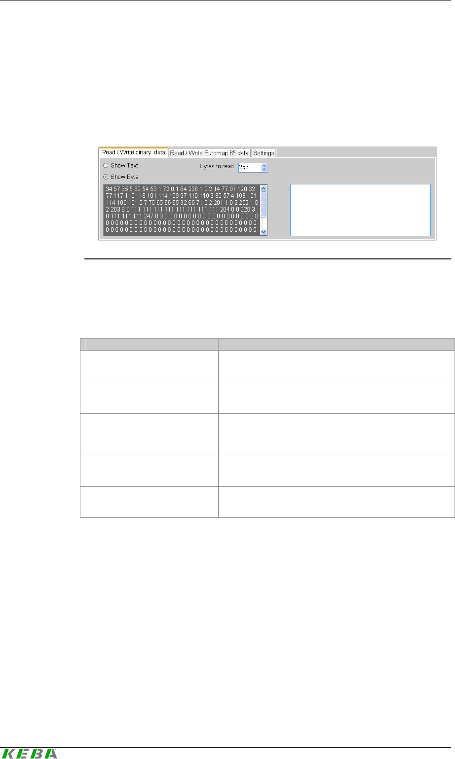
8.2.2 Tab page Read/Write Binary Data
Purpose
On this tab page data in binary format can be read out from or written onto
the transponder.
Demo application Kemro UserID classic / eco
58 User's Manual, Version: 1.01
© KEBA 2008
Description of the mask
The type of display (text / byte) and the number of bytes to be read out from
the transponder's user memory can be set in upper sector of the tab page.
Two fields are located below this. The left text field displays the user data
read out from the transponder. The right input field is used to enter data
that can be subsequently written into the user memory of the transponder.
Kemro UserID demo application - tab page read / write binary data
Description of the elements
Element Description
Show text The selection of this option displays the user data of the
transponder as text in the left text field.
Show byte The selection of this option displays the user data of the
transponder as byte characters in the left text field.
Bytes to read Number of Bytes to be read from the user memory of the
transponder (user data). The maximum storage memory
is specified by the selected transponder.
Text field (left) Here the user data of the transponder are displayed in
the selected display format after being read out.
Input field (right) Any type of content can be entered as text in the input
field. This content is written on the selected transponder
during the write process.
Usage of this mask
z Reading out user data in binary format from a transponder
z Writing user data in binary format onto a transponder
User Identification System Demo application
User's Manual, Version: 1.01 59
© KEBA 2008
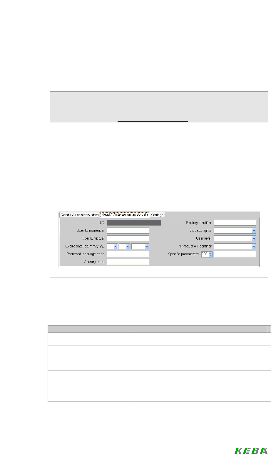
8.2.3 Tab page Read/Write Euromap 65 Data
Purpose
On this tab page data in Euromap 65 format can be read out from or written
onto the transponder.
Information
The Euromap 65 Standard is specifically matched to the requirements of
user identification on machines and plants. Additional information can be
found in the Internet at 0Hhttp://www.euromap.org/H.
Description of the mask
On this tab page the user data acc. to the Euromap65 standard are dis-
played. Here each Euromap 65 parameter is displayed in its own text field.
The parameters can also be modified in each field.
In selection field Specific parameters the reserved parameters acc. to the
Euromap 65 standard can be selected per index number (203-255) and
displayed and modified in the input field on the right.
Kemro UserID demo application - tab Read/Write Euromap 65 data
Description of the elements
Element Description
UID Display of UID of the read out transponder
User ID numerical Identification number of transponder profile
User ID textual Name of transponder profile
Expire date Expiry date of transponder. The transponder loses its
validity after this date. This enables the validity of lost
transponders to be limited in the application with regard
to time.

Demo application Kemro UserID classic / eco
60 User's Manual, Version: 1.01
© KEBA 2008
Element Description
Preferred language Language code of preferred language according to ISO
639-2/B (3-digit, e.g. eng for English).
Country code Country code acc. to ISO 3166-1 (2-digit, e.g. GB for
United Kingdom).
Factory identifier Company code
(note: a distinction is made between upper and lower
case letters in the input).
Access rights Access rights according to the Euromap65 standard with
the following options:
• 0 = no access
• 1 = lowest level
• 2 = middle level
• 3 = highest level
User level User level of transponder profile (0-255)
Reproduction identifier Identifier for rights for multiplication of the transponder
Recommended application:
0- writing of further transponders not possible
1- user can create transponder with low access rights.
2- user can create transponder with the same access
rights.
Specific parameters Selection of reserved parameters (203-255) acc. to Eu-
romap 65 standard. The value of the parameter is dis-
played or entered in the input field to the right.
Usage of this mask
z Reading out user data in Euromap 65 format from a transponder
z Writing user data in Euromap 65 format onto a transponder
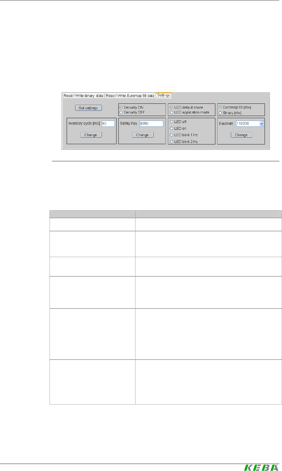
8.2.4 Tab Settings
Purpose
With this tab page the configuration of the Kemro UserID module can be
displayed and modified.
User Identification System Demo application
User's Manual, Version: 1.01 61
© KEBA 2008
Description of the mask
On this tab page all the configuration parameters of a Kemro UserID
module are displayed. The connected options are displayed in their own
sector with a surrounding border. Each parameter can be modified by an
entry or a selection.
Kemro UserID demo application - tab settings
Description of the elements
Element Description
Get settings Reading out settings.
Security ON / Security OFF Switching validation check on or off
(Note: when using the Euromap65 standard the valida-
tion check must be switched on.)
LED default mode The condition of the status LED is set directly by the
driver.
LED application mode The condition of the status LED is controlled by the ap-
plication. In this mode the condition and the color of the
status LED can be changed with the buttons in the lower
area of the mask.
Euromap 65 (r/w) With the selection of this option the configuration data of
the transponder are read and written in the Euromap65
format.
The setting applies only to write and read processes of
the configuration data. The format of the user data is
influenced by the selection of the other tab pages.
Binary (r/w) With the selection of this option the configuration data of
the transponder are read and written in binary format.
The setting applies only to write and read processes of
the configuration data. The format of the user data is
influenced by the selection of the other tab pages.

Demo application Kemro UserID classic / eco
62 User's Manual, Version: 1.01
© KEBA 2008
Element Description
Inventory cycle [ms] The cycle time with which the module searches for new
transponders in the detection range (typical value: 50
ms).
After the corresponding Change button is pressed this
setting is changed.
Safety key Key (32-bit safety key) for calculating the safety code
acc. to the Euromap 65 standard.
The safety code is calculated from the checksum of the
data stored on the transponder and this safety key (hid-
den factory safety key), and stored on trans-
ponders in Euromap 65 format.
After the corresponding Change button is pressed this
setting is changed.
LED off LED is switched off in the application mode
LED on LED lights up in the application mode
LED blink 1 Hz LED blinks once per second in the application mode
LED blink 2 Hz LED blinks twice per second in the application mode
Baud rate Transmission rate of serial interface.
After the corresponding Change button is pressed this
setting is changed.
Usage of this mask
z Displaying and changing the configuration of the Kemro UserID mo-
dule

User Identification System Function interface of device driver
User's Manual, Version: 1.01 63
© KEBA 2008
9 Function interface of device driver
With the aid of the Kemro UserID simple and easy integration into exist-
ing visualization systems is possible.
This chapter describes the commands of the device driver of the Kemro
UserID for accessing the module and transponders recognized by the
module.
9.1 Data format
Data can be stored on the RFID transponder either in Euromap 65 format,
or in binary form. The format is set by the write command used.
9.1.1 Euromap 65 Standard
The user data on the RFID transponder are displayed in Unicode UTF-8
format and stored with the byte sequence Low-Byte-First (Little-Endian).
The data are stored as a sequence of parameters and formatted as follows:
<ID><len><parameter...><ID><len><parameter...>...
Parameter Description
ID Identification of the parameter (8-bit value)
len Number of attached parameters in 8-bit units (optional,
depends on parameter)
parameter Value of the parameter
9.1.2 Binary format
When using the binary format the user data transferred to the device driver
are stored directly on the transponder. These data are not specially format-
ted.
9.2 Data structure
Information
An alignment of 1 applies to all data structures listed here

Function interface of device driver Kemro UserID classic / eco
64 User's Manual, Version: 1.01
© KEBA 2008
9.2.1 Data structure TEuromapData
This chapter describes all data elements which correspond to the optional
Euromap65 parameters.
Data element Euromap
65 ID # Description
DWORD TEuromapData::dwValid -- Switches the following structure
entries valid or invalid. A set bit
means that the data entry is filled
during reading and taken over
during writing. If the bit is not set,
the corresponding structure entry
is not used. One bit each acti-
vates/deactivates the specified
structure entry:
• Bit0: dwUserIdNumerical
• Bit1: strUserIdTextual
• Bit2: sExpiryDate
• Bit3: strLanguageCode
• Bit4: strCountryCode
• Bit5: strFactoryId
• Bit6: bAccessRights
• Bit7: bUserLevel
• Bit8: bReproductionId
• Bit9: rsOEMData
• Bit10-31: not used
The bit pattern can be used as
constants (see chapter Fehler!
Verweisquelle konnte nicht
gefunden werden.).
DWORD TEuromap-
Data::dwUserIdNumerical
0x01 Numerical user identification
char TEuromap-
Data::strUserIdTextual
0x02 Textual user identification
Maximum length of the text field:
16 characters
Note: The length by 1 byte larger
than in Euromap defines due to 0-
termination, further bytes due to
alignment of the structure.
TEuromapTime TEuromap-
Data::sExpiryDate
0x03 Expiry date of transponder
char TEuromap-
Data::strLanguageCode
0x04 Language code of user
It is recommended to store the
language code in line with ISO-
2/B.
Note: The length by 1 byte larger
than in Euromap defines due to 0-
termination.

User Identification System Function interface of device driver
User's Manual, Version: 1.01 65
© KEBA 2008
Data element Euromap
65 ID # Description
char TEuromap-
Data::strCountryCode
0x04 Country code of user
It is recommended to store the
language code in line with ISO-
1/B.
Note: The length by 1 byte larger
than in Euromap defines due to 0-
termination, further bytes due to
alignment of the structure.
char EuromapData::strFactoryId 0x05 Factory identification
Maximum length of the text field:
16 characters
Note: The length by 1 byte larger
than in Euromap defines due to 0-
termination.
BYTE TEuromap-
Data::bAccessRights 0x06 Access rights
BYTE TEuromapData::bUserLevel 0xC9 User level (Keba-specific)
Value range 0-255
BYTE TEuromap-
Data::bReproductionId
0xCA Reproduction code for the user
(Keba-specific)
Recommended application:
• 0:
writing of further transponders
not possible
• 1:
user can create transponder
with low access rights
• 2:
user can create transponder
with the same access rights
TeuromapOEMData TEuromap-
Data::rsOEMData
0xCB -
0xFF List with further, free Euromap
entries (OEM-specific)

Function interface of device driver Kemro UserID classic / eco
66 User's Manual, Version: 1.01
© KEBA 2008
9.2.2 Data structure TEuromapOEMData
This data structure is used to specify further free Euromap65 entries in the
Euromap65 format (ID 203-255).
Data element Euromap
65 ID # Description
BYTE TEuromapOEM-
Data::bEuromapID
0x1F -
0xC8 Specific machine manufacturer
parameters (these are issued
exclusively by the EUROMAP
organization,
H1Hhttp://www.euromap.orgH )
BYTE TEuromapOEMData::bDummy -- Dummy for structure alignment
WORD TEuromapOEMData::wLength -- Length of data of the Euromap65
entry defined by bEuromapID.
BYTE
TEuromapOEMData::rbEuromapData
[EUROMAP_OEM_DATALENGTH]
-- Data pointer of data of the Euro-
map65 entry defined by bEuro-
mapID.
9.2.3 Data structure TEuromapTime
This data structure is used to display the Euromap65 time specifications.
Data element Euromap
65 ID # Description
WORD TEuromapTime::wYear -- Year
BYTE TEuromapTime::bMonth -- Month (1-12)
BYTE TEuromapTime::bDay -- Day (1-31)
9.2.4 Data structure TFactorySettings
This data structure is used for reading the factory data of an RFID module.
Data element Euromap
65 ID # Description
DWORD TFactorySet-
tings::dwSerialNumber
-- Serial number of the RFID module

User Identification System Function interface of device driver
User's Manual, Version: 1.01 67
© KEBA 2008
9.2.5 Data structure TModuleSettings
This data structure is used for reading and writing the setting data of an
RFID module.
Data element Euromap
65 ID # Description
DWORD TModuleSet-
tings::dwInventoryRequestCycle
-- Cycle time for searching the new
transponders
DWORD TModuleSet-
tings::dwLedControlMode
-- Specification of who controls the
LEDs (default: 0):
• 0: driver takes over control.
• 1: the application takes over
control.
BOOL TModuleSet-
tings::boolCheckValidation
-- Specifies whether the validity of
the transponder is checked ac-
cording to Euromap 65 regulation.
unsigned short TModuleSet-
tings::usSafetyKey
-- Safety key for Euromap 65 encod-
ing
This key is used to together with
the data content of the trans-
ponder to calculate the safety
code.
DWORD TModuleSet-
tings::dwBaudrate
-- Baud rate of the Bus connection
for to the Kemro UserID mod-
ule
Note:
Only valid for units with serial
interfaces (Kemro UserID
classic).
9.2.6 Data structure TRfidDeviceName
This data structure is used in connection with the device name of a
Kemro UserID module.
Data element Euromap
65 ID # Description
char TRfidDevice-
Name::strDeviceName
-- Name of Kemro UserID
modules

Function interface of device driver Kemro UserID classic / eco
68 User's Manual, Version: 1.01
© KEBA 2008
9.2.7 Data structure TRfidUid
This data structure is used in connection with the clear identification of a
transponder.
Data element Euromap
65 ID # Description
unsigned char TRfidUid::uid -- Clear transponder ID
9.2.8 Data structure for Callback
The Event Callback is used to signal transponder or device actions.
typedef void __stdcall TEventCallback(const TRfidDeviceName sDevice-
Name, TRfidUid sTag, const TRfidAction eAction)
Parameter Description
sDeviceName Name of device that has caused the action
sTag Name of transponder that has caused the
action
eAction The action that was carried out
The following actions are signaled via this Callback.
Action Description
eAction • 0: New Kemro UserID module added (sTag is transmit-
ted as 0)
• 1: Kemro UserID module was removed
• 2: Valid transponder found
• 3: Copied transponder was found (security check has
failed)
• 4: New / empty / transponder was found
• 5: Non-readable transponder was found
• 6: Known transponder was removed
Information
If a
Kemro UserID
module or a transponder is removed and it is open
(rfidOpenDevice/rfidOpenTag), then the connection with regard to this
Callback is to be closed (rfidCloseDevice/rfidCloseTag), since the
respective Handle looses its validity when removed.
NOTICE
• Under no circumstance is blocking and waiting for something during
the Callback permitted. Editing during Callback must be short and fast.
User Identification System Function interface of device driver
User's Manual, Version: 1.01 69
© KEBA 2008
9.3 Enumeration types
9.3.1 Call-up actions of the Event Callback
enum TRfidAction
Enumeration values Description
RfidAction_NewDevice New Kemro UserID module added (sTag is
transmitted as 0)
RfidAction_DeviceRemoved Kemro UserID module was removed
RfidAction_ValidTagFound Valid transponder found
RfidAction_CopiedTagFound Copied transponder was found (security check
has failed)
RfidAction_EmptyTagFound New / empty / transponder was found
RfidAction_UnreadableTagFound Non-readable transponder was found
RfidAction_TagRemoved Known transponder was removed
9.3.2 Operating state of the Status LED
enum TRfidLedStatus
Enumeration values Description
RfidLedStatus_Off LED off (continuous)
RfidLedStatus_On LED on (continuous)
RfidLedStatus_Slow LED blinking slowly (1 Hz)
RfidLedStatus_Fast LED blinking fast (2 Hz)
9.3.3 Color of the Status LED
enum TRfidLedColor
Enumeration values Description
RfidLedColor_Red Led illuminated/blinks red
RfidLedColor_Green Led illuminated/blinks green
RfidLedColor_Orange Led illuminated/blinks orange

Function interface of device driver Kemro UserID classic / eco
70 User's Manual, Version: 1.01
© KEBA 2008
9.4 Constants
Constant Value Description
USER_ID_LENGTH 16 Maximum length of the textual user identification
FACTORY_ID_LENGTH 16 Maximum length of the textual factory identifica-
tion
LANGUAGECODE_LENGTH 3 Number of language code bBytes
COUNTRYCODE_LENGTH 2 Number of country code bytes
OEM_DATA_LENGTH 53 Maximum number of user commands (ID 0xcb to
ID 0xff)
FLAG_OPEN_EUROMAP65 1 Transponder connection is opened in Euromap65
format
FLAG_OPEN_BINARY 2 Transponder connection is opened in binary for-
mat
RFID_DEVICENAME_LENGTH 50 Maximum length of module name
EUROMAP_OEM_DATALENGTH 256 Maximum length of an OEM data entry
EUROMAP_VALID_USERID_NUMERICAL 0x0001 The entry "UserID-Numerical“ of the Euromap
structure contains valid data for writing/reading
EUROMAP_VALID_USERID_TEXTUAL 0x0002 The entry "UserId-textual“ of the Euromap struc-
ture contains valid data for writing/reading
EUROMAP_VALID_EXPIRY_DATE 0x0004 The entry "Expiry Date“ of the Euromap structure
contains valid data for writing/reading
EUROMAP_VALID_LANGUAGE_CODE 0x0008 The entry "Language Code“ of the Euromap struc-
ture contains valid data for writing/reading
EUROMAP_VALID_COUNTRY_CODE 0x0010 The entry "Country Code“ of the Euromap struc-
ture contains valid data for writing/reading
EUROMAP_VALID_FACTORY_ID 0x0020 The entry "FactoryID“ of the Euromap structure
contains valid data for writing/reading
EUROMAP_VALID_ACCESS_RIGHTS 0x0040 The entry "Access Right“ of the Euromap struc-
ture contains valid data for writing/reading
EUROMAP_VALID_KEBA_USER_LEVEL 0x0080 The entry "User Level“ of the Euromap structure
contains valid data for writing/reading
EUROMAP_VALID_KEBA_REPRODUCTION_ID 0x0100 The entry "ReproductionId“ of the Euromap struc-
ture contains valid data for writing/reading
EUROMAP_VALID_OEM_DATA 0x0200 The entry "OEM Data“ of the Euromap structure
contains valid data for writing/reading
EUROMAP_ID_USERID_NUMERICAL 0x01 UserId-Numerical entry

User Identification System Function interface of device driver
User's Manual, Version: 1.01 71
© KEBA 2008
Constant Value Description
EUROMAP_ID_USERID_TEXTUAL 0x02 UserId-Textual entry
EUROMAP_ID_EXPIRY_DATE 0x03 Expiry-Date entry
EUROMAP_ID_PREFERED_LANGUAGE 0x04 Language and Country-Code entry
EUROMAP_ID_FACTORY_ID 0x05 FactoryID entry
EUROMAP_ID_ACCESS_RIGHTS 0x06 Access-Rights entry
EUROMAP_ID_KEBA_USER_LEVEL 0xc9 User-Level entry
EUROMAP_ID_KEBA_REPRODUCTION_ID 0xca ReproductionId entry
9.5 Functions
9.5.1 Registration of an Event Callback
DWORD rfidRegisterEventCallback (TEventCallback * pfnEventCallback)
Parameter Description
pfnEventCallback Callback function that is called up with the
previously described actions
A Callback can be registered with this function which is called up in the
subsequent action. (see definition of T_EventCallback):
z 0.....New RFID module added (sTag is transmitted as 0)
z 1.....Kemro UserID module was removed
z 2.....Valid transponder found
z 3.....Copied transponder was found (security check has failed)
z 4.....New / empty / transponder was found
z 5.....Non-readable transponder was found
z 6.....Known transponder was removed
The de-registration of a Callback is carried out by transferring a ZERO
pointer as Callback pointer
Return
Value Description
0 If everything is OK, otherwise descriptive error code

Function interface of device driver Kemro UserID classic / eco
72 User's Manual, Version: 1.01
© KEBA 2008
9.5.2 Read out list of currently connected Kemro UserID modules
DWORD rfidGetDeviceList (TRfidDeviceName rsDeviceName[], DWORD *
pdwCount)
Parameter Description
rsDeviceName String list in which the automatically generated symbolic
names of the Kemro UserID modules are written
pdwCount In Length of string list
Out: Number of entered RFID modules
This function lists all Kemro UserID modules found (independent of con-
nection, USB or RS232). The symbolic names specified are generated
automatically and can continue to be used to open a Kemro UserID
module with rfidOpenDevice, to control LEDs or to read or modify the
settings of the module.
Return
Value Description
0 If everything is OK, otherwise descriptive error code
9.5.3 Opening a connection to a Kemro UserID module
DWORD rfidOpenDevice (const TRfidDeviceName sDeviceName, HANDLE *
phDevice)
Parameter Description
sDeviceName Symbolic name of Kemro UserID module to be opened
phDevice Pointer on the Handle of the opened Kemro UserID mod-
ule
This function opens the data connection to a Kemro UserID module and
supplies a Handle with which the data of the Kemro UserID module can
continue to be accessed.
Return:
Value Description
0 If everything is OK, otherwise descriptive error code
9.5.4 Closing a connection to an opened Kemro UserID module
void rfidCloseDevice (HANDLE hDevice)
Parameter Description
hDevice Name of the opened Kemro UserID module

User Identification System Function interface of device driver
User's Manual, Version: 1.01 73
© KEBA 2008
9.5.5 Controlling the LED of the Kemro UserID module
DWORD rfidSetLedStatus (HANDLE hDevice, TRfidLedStatus eStatus,
TRfidLedColor eColor)
Parameter Description
hDevice Handle on the Kemro UserID module whose Led is to be
controlled
eStatus Operating status of the LED.
• 0: Off
• 1: On
• 2: Slowly flashing (1Hz)
• 3: Fast flashing (2Hz)
eColor Color of the LED
• 0: Red
• 1: Green
• 2: orange
This function controls the operating state of the LED and switches the LED
off/on and controls its color.
Information
The LED can only be controlled when the control for the LED has been re-
leased in the settings for the application. Otherwise the driver takes over
the exclusive control of the LED.
Return:
Value Description
0 If everything is OK, otherwise descriptive error code
9.5.6 Reading out current settings of the Kemro UserID module
DWORD rfidGetModuleSettings (HANDLE hDevice, TModuleSettings *
psModuleSettings)
Parameter Description
hDevice Handle on the Kemro UserID module
psModuleSettings Setting data of the Kemro UserID module
The current device driver settings are supplied for this Kemro UserID
module.
Return:
Value Description
0 If everything is OK, otherwise descriptive error code

Function interface of device driver Kemro UserID classic / eco
74 User's Manual, Version: 1.01
© KEBA 2008
9.5.7 New settings for the Kemro UserID module
DWORD rfidSetModuleSettings (HANDLE hDevice, TModuleSettings *
psModuleSettings)
Parameter Description
hDevice Handle on the Kemro UserID module
psModuleSettings New setting data of the Kemro UserID module
The current device driver settings are set for this Kemro UserID module.
Return:
Value Description
0 If everything is OK, otherwise descriptive error code
9.5.8 Reading out the factory settings of the Kemro UserID module
DWORD rfidGetFactorySettings (HANDLE hDevice, TFactorySettings *
psFactorySettings)
Parameter Description
hDevice Handle on the Kemro UserID module
psFactorySettings Factory data of the Kemro UserID module
The Kemro UserID module data entered at the factory are read out and
supplied.
Return:
Value Description
0 If everything is OK, otherwise descriptive error code
9.5.9 Creating a list of currently recognized transponders
DWORD rfidGetTagList (HANDLE hDevice, TRfidUid rsUids[], DWORD *
pdwCount)
Parameter Description
hDevice Handle on the Kemro UserID module whose transponder
is to be determined
rsUids List into which the UIDs of the detected transponders are
written
pdwCount In: Length of UID list.
Out: Number of entered transponders
This function lists all detected transponders for the specified Kemro
UserID module. The UIDs are required to establish a data connection to a
transponder (rfidOpenTag).

User Identification System Function interface of device driver
User's Manual, Version: 1.01 75
© KEBA 2008
Return:
Value Description
0 If everything is OK, otherwise descriptive error code
9.5.10 Opening a connection to a specific transponder
DWORD rfidOpenTag (TRfidUid sUid, DWORD dwFlags, HANDLE * phTag)
Parameter Description
sUid UIDs of the transponder to be opened
dwFlags Data mode in which the transponder is to be opened
• FLAG_OPEN_EUROMAP65: opens the connection in the
Euromap65 standard, i.e. at rfidRead-
Tag/rfidWriteTag data in the form of a
T_EuromapData structure are expected (pvData is of
type T_EuromapData *).
• FLAG_OPEN_BINARY: opens the connection in the bi-
nary mode, i.e. binary data are expected at rfidRead-
Tag/rfidWriteTag (pvData is of type BYTE *). The
transmitted data correspond 1:1 to the memory dump of
the transponder, without any formatting.
phTag Pointer on the Handle of the opened transponder
This function opens the data connection to a transponder and supplies a
Handle with which the data of the transponder can continue to be ac-
cessed.
Information
Opening in the Euromap65 mode is only possible when the safety code
check (boolCheckValidation = 1) has been activated. If the validation
check is deactivated, the rfidOpenTag issues an error. Specifying the
Kemro UserID
module is not necessary here, since the transponders are
administered centrally for all
Kemro UserID
modules.
Return:
Value Description
0 If everything is OK, otherwise descriptive error code
9.5.11 Closing a connection to an opened transponder
void rfidCloseTag (HANDLE hTag)
Parameter Description
hTag Handle of the opened transponder

Function interface of device driver Kemro UserID classic / eco
76 User's Manual, Version: 1.01
© KEBA 2008
9.5.12 Reading out data from a transponder
DWORD rfidReadTag (HANDLE hTag, void * pvData, DWORD dwCount, DWORD
* pdwCountRead)
Parameter Description
hTag Handle of the transponder to be read
pvData Buffer for the data read out. The data have the following
format, depending on the data mode in which the trans-
ponder was opened:
• FLAG_OPEN_EUROMAP65: a data buffer in the form of a
T_EuromapData structure is expected. Those fields of
the structure that are activated by dwValid (at parame-
ter transfer [in]), are filled during reading out, the fields
not activated remain unaffected.
• FLAG_OPEN_BINARY: a byte array of adequate size is
expected. The data are copied from the transponder into
the buffer in binary form (1:1 image)
dwCount FLAG_OPEN_EUROMAP65: number of structures to be read,
must be permanently set on 1.
• FLAG_OPEN_BINARY: number of bytes to be read.
pdwCountRead FLAG_OPEN_EUROMAP65: number of the structures read, 1
if reading was possible, otherwise 0.
• FLAG_OPEN_BINARY: number of bytes read.
This function reads the data of an opened transponder. The data are sup-
plied in the form of Euromap65 structure or as binary data depending on
how the connection to the transponder was opened.
Return:
Value Description
0 If everything is OK, otherwise descriptive error code

User Identification System Function interface of device driver
User's Manual, Version: 1.01 77
© KEBA 2008
9.5.13 Writing data of a transponder
DWORD rfidWriteTag (HANDLE hTag, void * pvData, DWORD dwCount, DWORD
* pdwCountWritten)
.
Parameter Description
hTag Handle of the transponder to be written
pvData Buffer that contains the data to be written. The data have the
following format, depending on the data mode in which the
transponder was opened:
• FLAG_OPEN_EUROMAP65: a data buffer in the form of a
T_EuromapData structure is expected. Those fields of
the structure that are activated by dwValid are taken
over, the fields not activated remain unaffected.
• FLAG_OPEN_BINARY: a byte array of adequate size is
expected. The data are taken over in binary form and
copied into the transponder (1:1 image).
dwCount FLAG_OPEN_EUROMAP65: number of structures to be writ-
ten, must be permanently set on 1.
• FLAG_OPEN_BINARY: number of bytes to be written.
pdwCountWritten FLAG_OPEN_EUROMAP65: number of the structures written,
1 if writing was possible, otherwise 0.
• FLAG_OPEN_BINARY: number of bytes written.
This function writes the data of an opened transponder. The data are ex-
pected in the form of Euromap65 structure or as binary data depending on
how the connection to the transponder was opened.
Return:
Value Description
0 If everything is OK, otherwise descriptive error code

Diagnosis Kemro UserID classic / eco
78 User's Manual, Version: 1.01
© KEBA 2008
10 Diagnosis
The following states can be signaled with the status LED:
Display Description
LED off Kemro UserID module is not supplied
Only with Kemro UserID eco:
The module has not yet been detected by the device driver or the
device driver for the module has not been installed yet.
red (continuous) Firmware of the module is loaded
orange (continu-
ous) Firmware is loaded, data communication with device driver on the
host system is established
green / orange
(blinking) Supply and data communication with device driver on the host sys-
tem exists
green (continu-
ous) Default behavior of the module, as soon as the device driver has
instantiated the module at least one time.
green (blinking,
max. 3 sec.) Readable transponder detected
The status LED blinks green as long as the transponder is within
reading range (max. 3 sec.)
red (blinking,
max. 3 sec.) Transponder could not be read; unsupported transponder type
The status LED blinks red as long as the transponder is within read-
ing range (max. 3 sec.)

User Identification System Maintenance and repair instructions
User's Manual, Version: 1.01 79
© KEBA 2008
11 Maintenance and repair instructions
11.1 Maintenance
This device does not require regular maintenance.
11.2 Repair
A defective device may only be repaired by KEBA specialists, otherwise the
warranty claim expires. This is to be sent to KEBA in a suitable transport
packaging.
11.2.1 Packaging, shipment
The module is wrapped in protective packaging material for shipment.
The protective packaging does not qualify as adequate transport packaging
and hence is not suited for transportation via carrier haulage or airplane.
Appropriate transportation packaging is required for these types of ship-
ment.
Disposal Kemro UserID classic / eco
80 User's Manual, Version: 1.01
© KEBA 2008
12 Disposal
12.1 Disposal of the module
• The symbol with the crossed-out rubbish bin indicates that electrical
and electronic devices including their accessories should not be dis-
posed of in the household garbage.
• Depending on their coding, the raw materials are recyclable. By dispos-
ing of such used devices correctly, you can ensure that they can be re-
used, their raw materials recycled or put to another use, and you will be
making an important contribution to the protection of our environment!

User Identification System Technical data
User's Manual, Version: 1.01 81
© KEBA 2008
13 Technical data
General information
Power consumption:
(Kemro UserID eco)
Max. 0.75 W
Power consumption:
(Kemro UserID classic)
Max. 1 W
Reading range: Up to 6 cm from the housing / antenna (depending on the
installation situation, the transponder design and the number
of transponders)
Supported transponders: Transponders according to ISO/IEC 15693 in any form
(Tag-it, I-Code SLI)
Signaling: Three-color LED on the front side of the housing / on the
antenna print
Device driver for the operation sys-
tems: Windows 2000, Windows 2003 Server, Windows CE, Win-
dows XP pro, Windows XP emb., Windows Vista
Interfaces
Data interface: RS 232 – bei Kemro UserID classic
USB 2.0 (12 Mbit) – bei Kemro UserID eco
Power supply voltage: 12 V / 24 V DC – for Kemro UserID classic
USB bus powered – for Kemro UserID eco
Communication connecting plug: DSUB 9 pol. (female) – for Kemro UserID classic
stand-alone and OEM – variants C-OEM and D-OEM
USB type B – for Kemro.UserID eco stand-alone and
OEM – variants C-OEM and D-OEM
Terminal block: Kemro UserID OEM variants A-OEM and
B-OEM classic and eco
Supply connecting plug: Only Kemro UserID classic (IC 140/A, IC 140/C-OEM,
IC 140/D-OEM): 2-pole plug
RF signal
Frequency range: 13.56 MHz
Transmitting power: Typical 200 mW (max. 250 mW)
Chip set: Melexis
Casing, dimensions
Stand-alone module: Width: 77 mm
Length: 65.4 mm
Height: 46.3 mm
Antenna print small: Width: 50 mm
Length: 30 mm
Antenna print large: Width: 57 mm
Length 53 mm
Evaluation unit with housing: Width: 94 mm
Length: 54 mm
Height: 24 mm
Evaluation unit without housing: Width: 70 mm
Length: 50 mm
Height: 11 mm

Technical data Kemro UserID classic / eco
82 User's Manual, Version: 1.01
© KEBA 2008
Transportation and Environmental conditions
Operating temperature: +0 °C to +65 °C (OEM variants)
+5 °C to +55 °C (stand-alone variant)
Storage temperature: -25 °C to +70 °C
Relative humidity of air: 5 % to 95 % (non condensing)
Vibration resistance: according to EN 61131-2
Shock resistance: according to EN 61131-2
13.1 Stand-alone versions
General Information
Housing: Robust plastic housing PC / ABS Bayblend FR3010
Device installation: Direct installation in opening of the front plate,
fastening with retaining screws
Protection class: IP65 (front-sided); IP20 (back-sided)
Housing material fire-resistant according to UL 94
Wall thickness for the installation: 1.5 mm to 6 mm
13.2 OEM versions
General Information
Antenna installation: Antenna installation flush with front plate possible
corresponding to the installation guidelines
Transmission range evaluation unit: Evaluation unit can be positioned up to 30 cm from the an-
tenna
Connection antenna - evaluation unit Plug-in
Sheet metal housing: Only for versions C-OEM and D-OEM.
Contact protection (IP 20) and fitting aid of the evaluation unit
Protection class: IP20

User Identification System EC directives and standards
User's Manual, Version: 1.01 83
© KEBA 2008
14 EC directives and standards
14.1 EC Directives
Directive 1999/5/EG R&TTE Directive
(Radio & Telecommunications Terminal Equipment)
Directive 2002/95/EG RoHS directives
14.2 Standards
The following, legally non-binding European standards, were applied in or-
der to check that the Kemro K2 System conforms with the Directives.
14.2.1 R & TTE
EN 300330-2 Electromagnetic compatibility and radio spectrum matters
(ERM);
Short range devices (SRD);
Radio equipment with operating frequencies in the range of 9
kHz to 25 MHz and induction loop systems in the range of 9
kHz to 30 MHz
EN 301489-01 Electromagnetic compatibility and radio spectrum matters
(ERM);
Electromagnetic compatibility for radio equipment and –
services
Part 1: General technical requirements
EN 301489-03 Electromagnetic compatibility and radio spectrum matters
(ERM);
Electromagnetic compatibility for radio equipment and –
services;
Part 3: Specific conditions for short range radio devices
(SRD) for the use on frequencies between 9 kHz and 40 Ghz
EN 50364 Limit of the exposition of persons to electromagnetic fields of
devices that are operated in the frequency range of 0 Hz to
10 GHz and used in the electronic article monitoring (en:
EAS), high-frequency identification (en: RFID) and similar
applications
EN 60950-1 Information Technology Equipment – Safety; Part 1
14.2.2 Other Standards and recommendations
In addition, partial aspects of the following legally non-binding stan-
dards/recommendations were consulted:
EN 61000-6-2 Electromagnetic compatibility (EMC) – Part 6-2:
Generic standards – Immunity for industrial environments
EN 61000-6-4 Electromagnetic compatibility (EMC) – Part 6-2:
Generic standards – Emission standard for industrial einvi-
ronments

EC directives and standards Kemro UserID classic / eco
84 User's Manual, Version: 1.01
© KEBA 2008
14.2.3 Environmental and surrounding conditions
EN 61131-2 Stored-program controls – Part 2
IEC 60068-2-6 Vibration, test FC
IEC 60068-2-27 Shock
14.3 Standards for the American market
14.3.1 UL test for industrial control equipment
UL 508, 2005 Industrial Control Equipment
14.3.2 FCC
CFR 47 Part 15 Radio Frequency Devices
14.3.2.1 FCC Requirements
The device complies with Part 15 of the FCC Rules. Operation in subject to
the following two conditions:
1. this device may not cause harmful interference, and
2. this device must accept any interference received, including in-
terference that may cause undesired operation.
This device is labelled with an FCC ID number.
If this label is not visible when installed in an end device, the outside of the
device MUST also display a label referring to the enclosed module.
Contains FCC ID: U870002 - IC 140/A
(Kemro UserID classic Stand Alone)
Contains FCC ID: U870003 – IC 140/C - OEM
U870003 – IC 140/D – OEM
(Kemro UserID classic OEM)
Contains FCC ID: U870004 – IE 160/A
(Kemro UserID eco Stand Alone)
Contains FCC ID: U870005 – IE 160/C – OEM
U870005 – IE 160/D – OEM
(Kemro UserID eco OEM)
Information
No other antennas except the one provided by KEBA shall be used.
Changes or modifications not expressly approved by KEBA could void the
user's authority to operate the equipment.