KEBA 0005 RFID transceiver working at 13.56 MHz User Manual kemro userid bden
KEBA AG RFID transceiver working at 13.56 MHz kemro userid bden
UserManual.wiki
>
KEBA
>
0005 User Manual
user manual
Navigation menu
Upload a User Manual
Namespaces
Wiki Guide
HTML
PDF
Info
Views
User Manual
Discussion / Help
Navigation
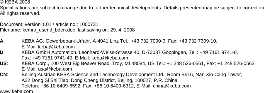
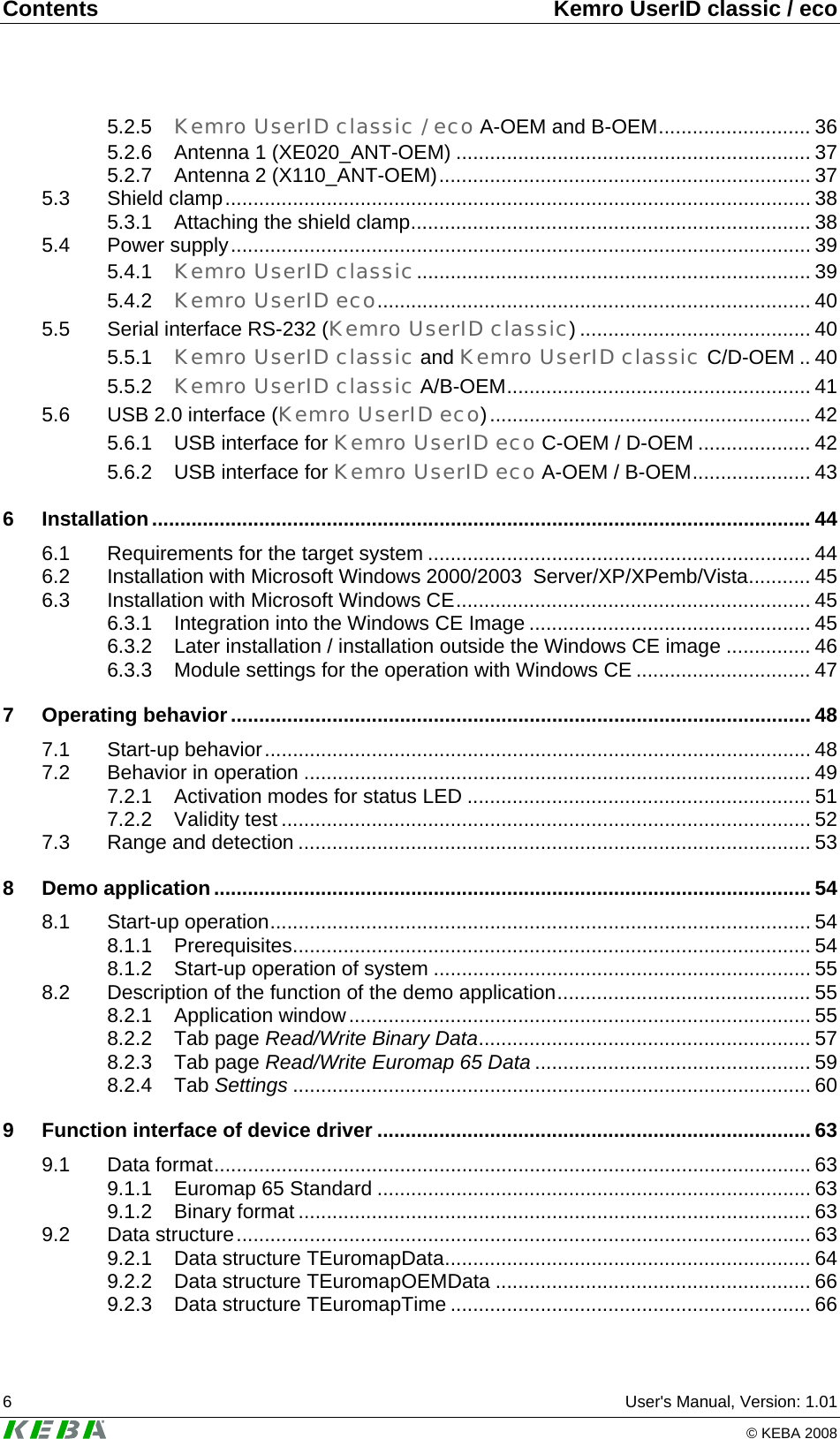

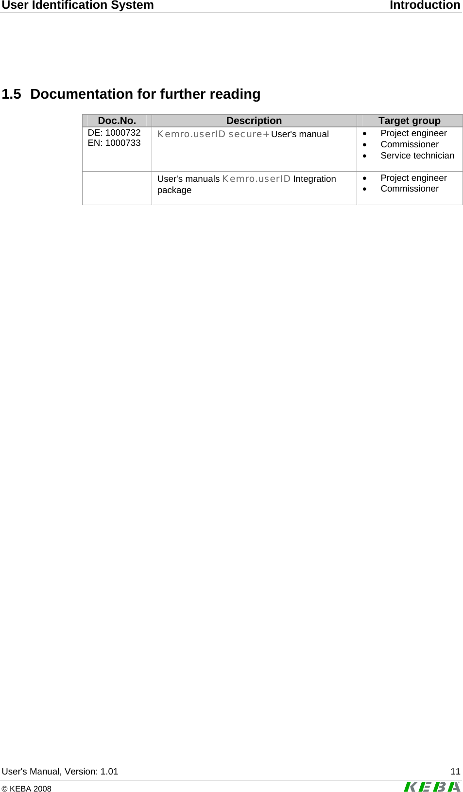


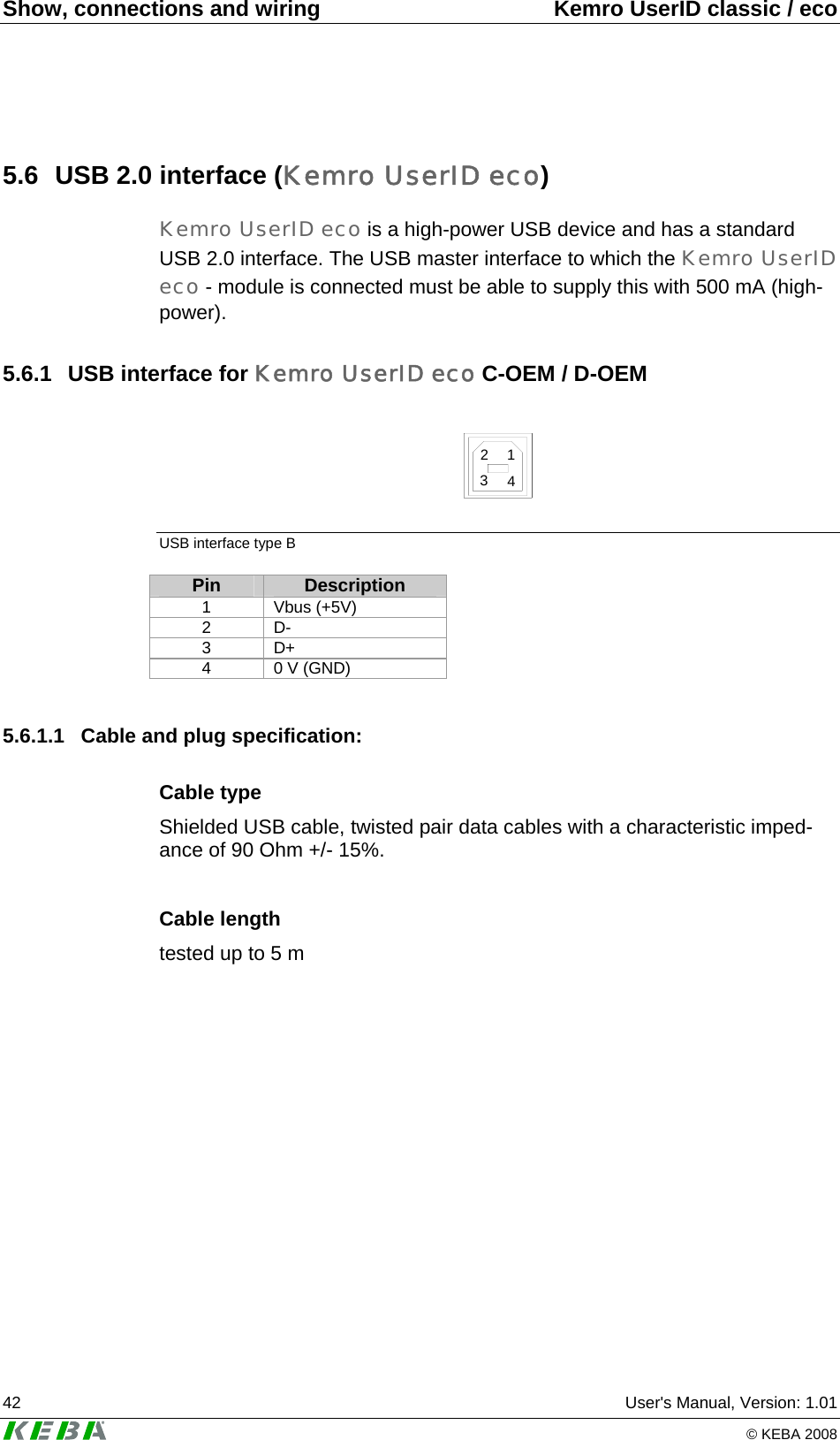
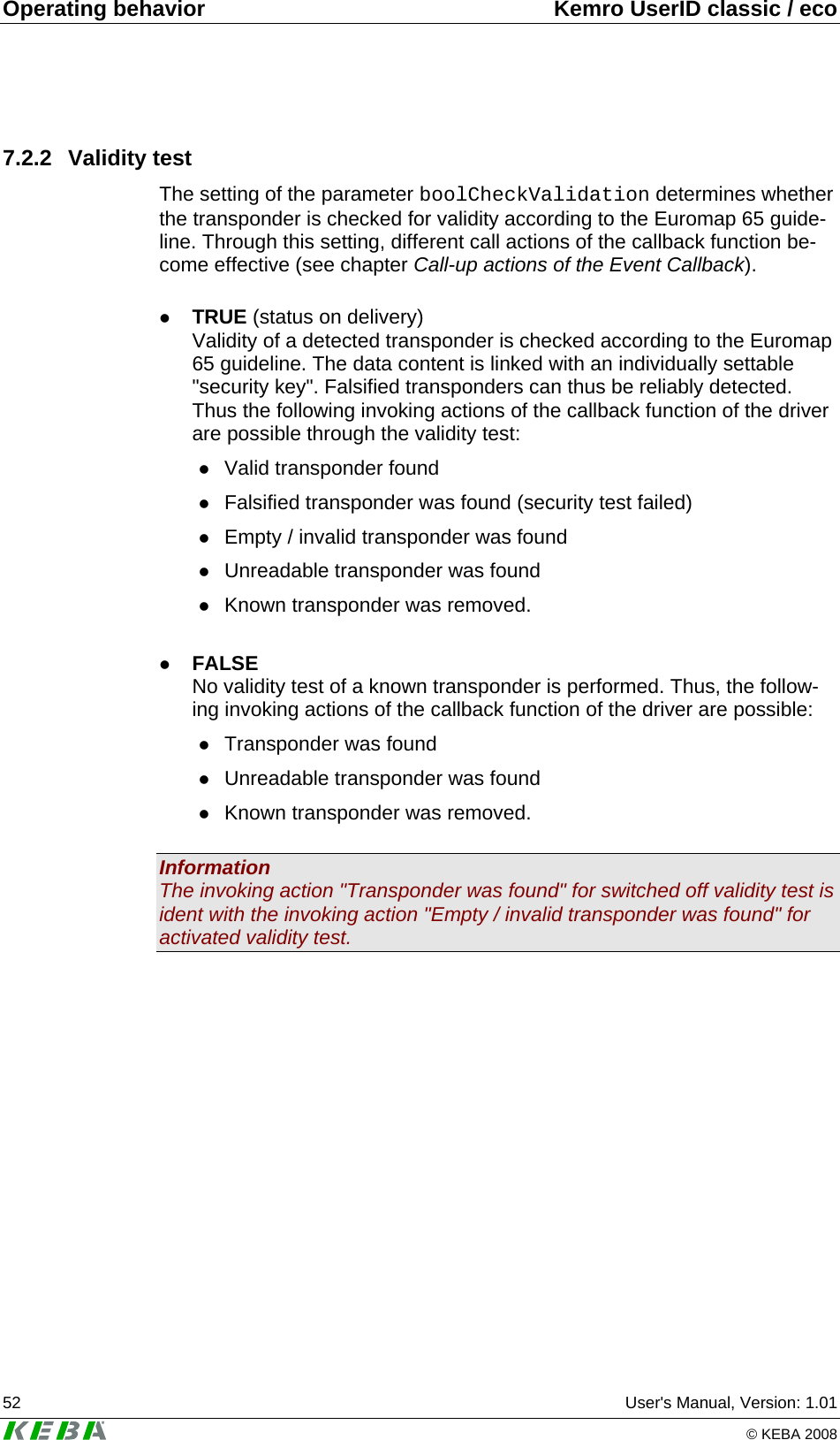
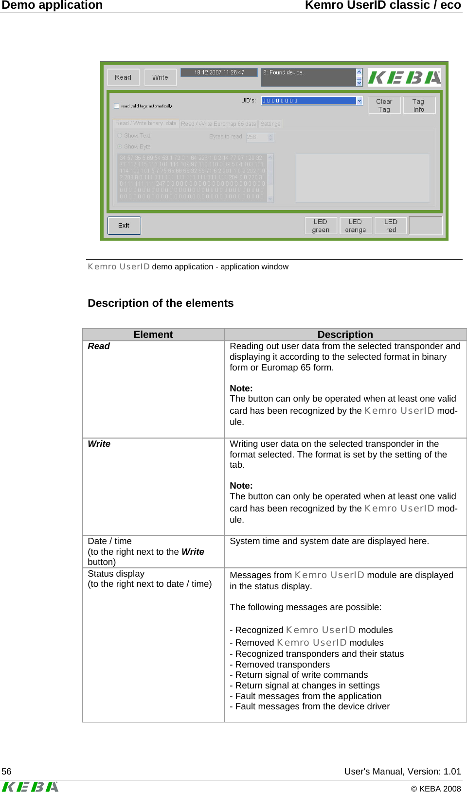
![Installation Kemro UserID classic / eco 46 User's Manual, Version: 1.01 © KEBA 2008 6.3.2 Later installation / installation outside the Windows CE image 1.) Start target system. 2.) Copy the files SIUSBXP.dll SIUSBXP_LIB.dll UIDDRV_RfbCommUsb.dll UIDDRV_RfbMaster.dll UIDDRV_RfbInterface.dll UIDDRV_RfidInterface.dll UIDDRV_RfidService.dll of directory <Kemro UserID CD>\drivers\win_ce into a non-volatile directory (e.g. flash drive, a hard disc or a battery-buffered Ram) 3.) Take over the registry entries of file UIDDRV_Win32ce_RfidService.reg into the registry of the target system and at the same time change the path of entry Dll to the path under which file UIDDRV_RfidService.dll was stored . The registry can be edited via a remote registry editor if the target system has no registry editor available. The suitability of the editor depends on the Windows CE image and the CPU used. Additional in-formation is available from the manufacturer of the target system. 4.) Now connect the Kemro UserID module to the target system. The target system will now display a dialog in which you are requested to enter the driver for the new device. Now specify the file <pfad>\SIUSBXP.dl, which could not be copied into the non-volatile directory of the target system. If this dialog is not displayed the registry key [HKEY_LOCAL_MACHINE\DRIVERS\USB\LoadClients\Default\Default\255] is to be deleted in the target system with the aid of the registry editor. The connecting cable to the Kemro UserID mo-dule must then be unplugged and again plugged in. The dialog should now be displayed. 5.) Re-start the target system. The drivers necessary for operation are installed and Kemro UserID can now be used from all windows-based application development systems.](https://usermanual.wiki/KEBA/0005/User-Guide-937325-Page-46.png)

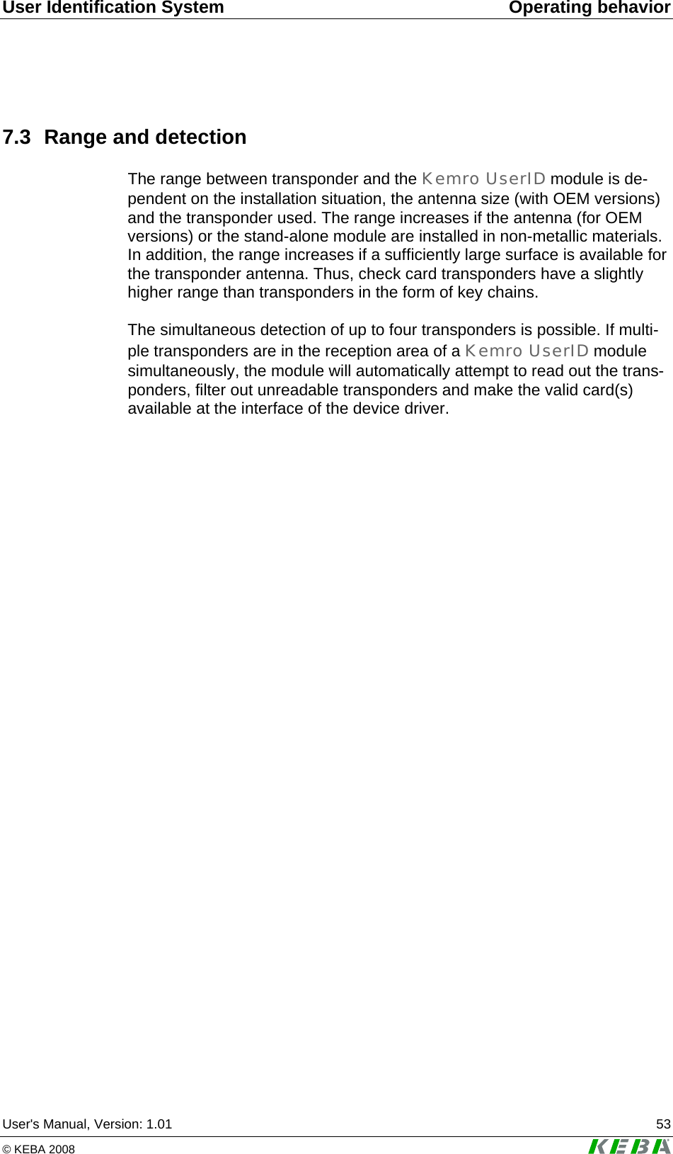
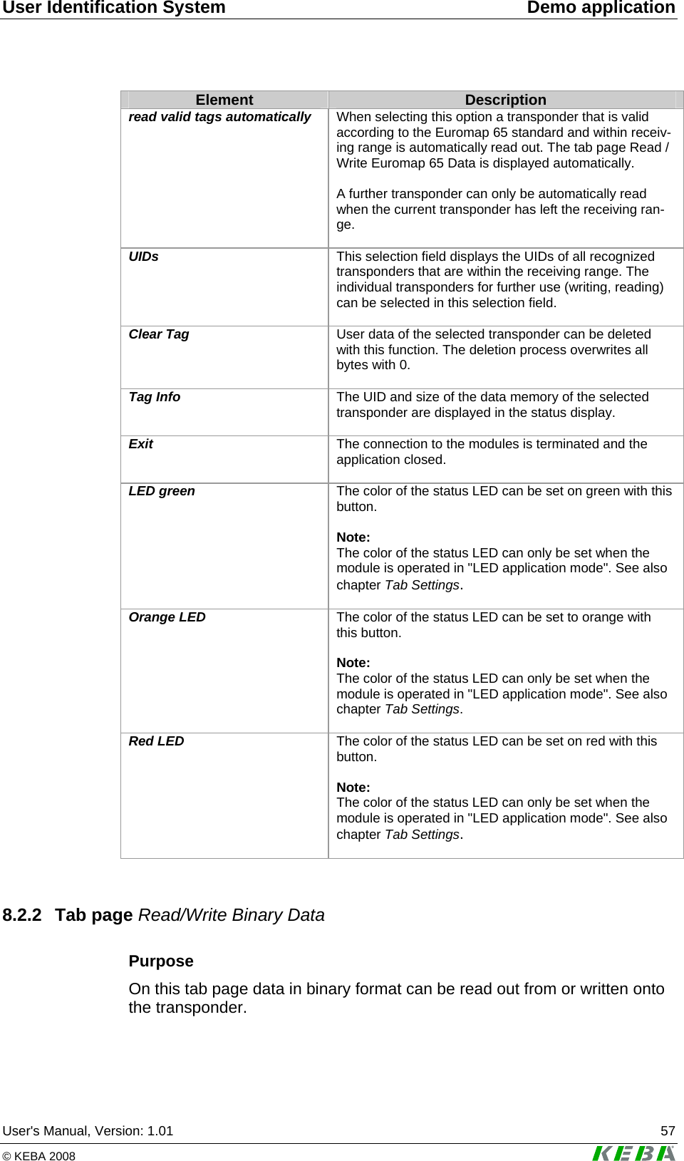
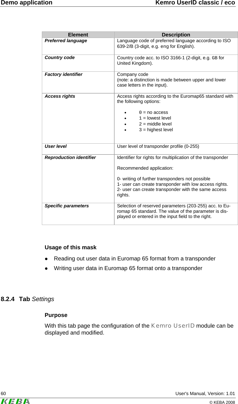
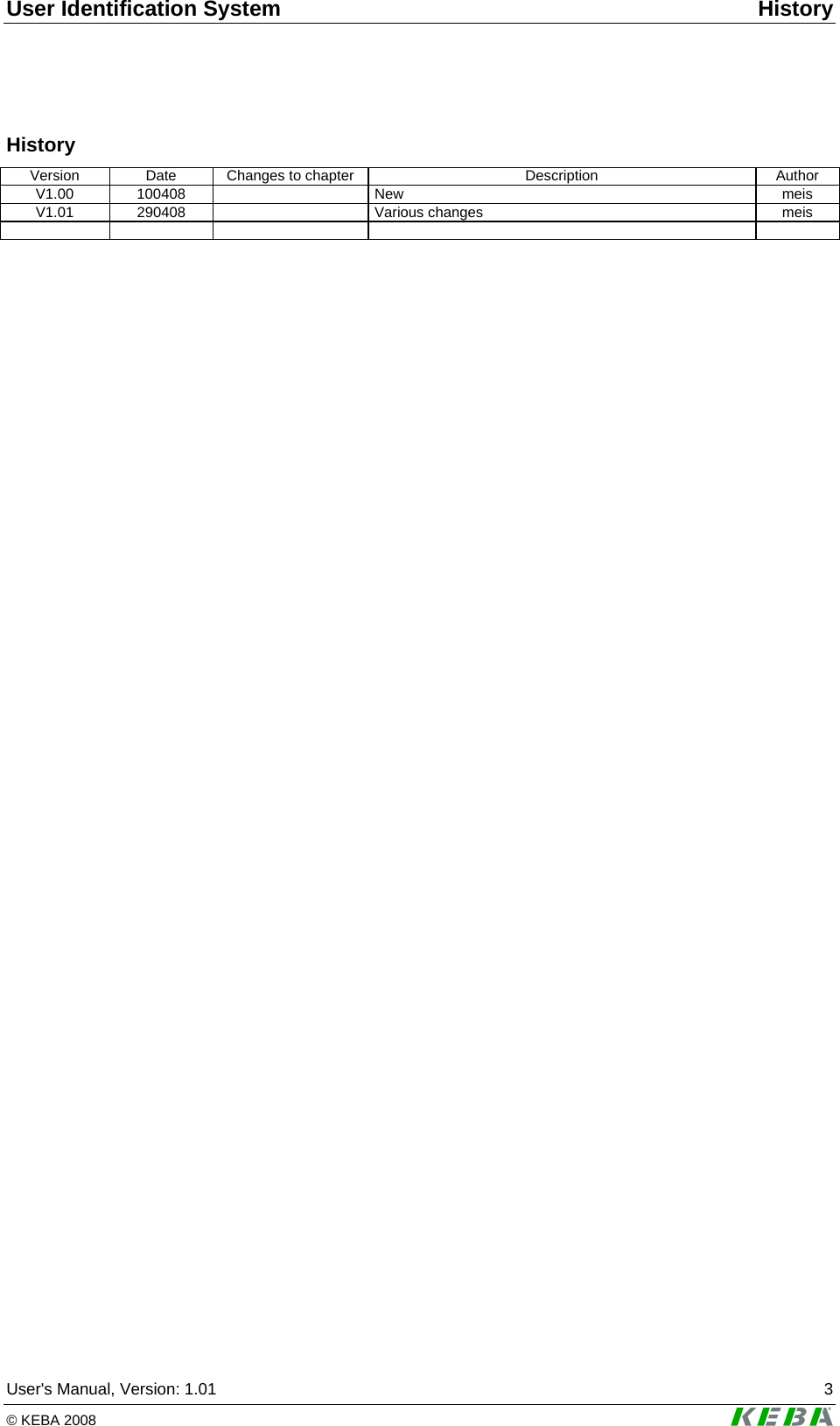
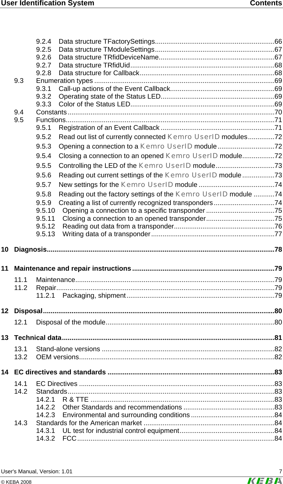
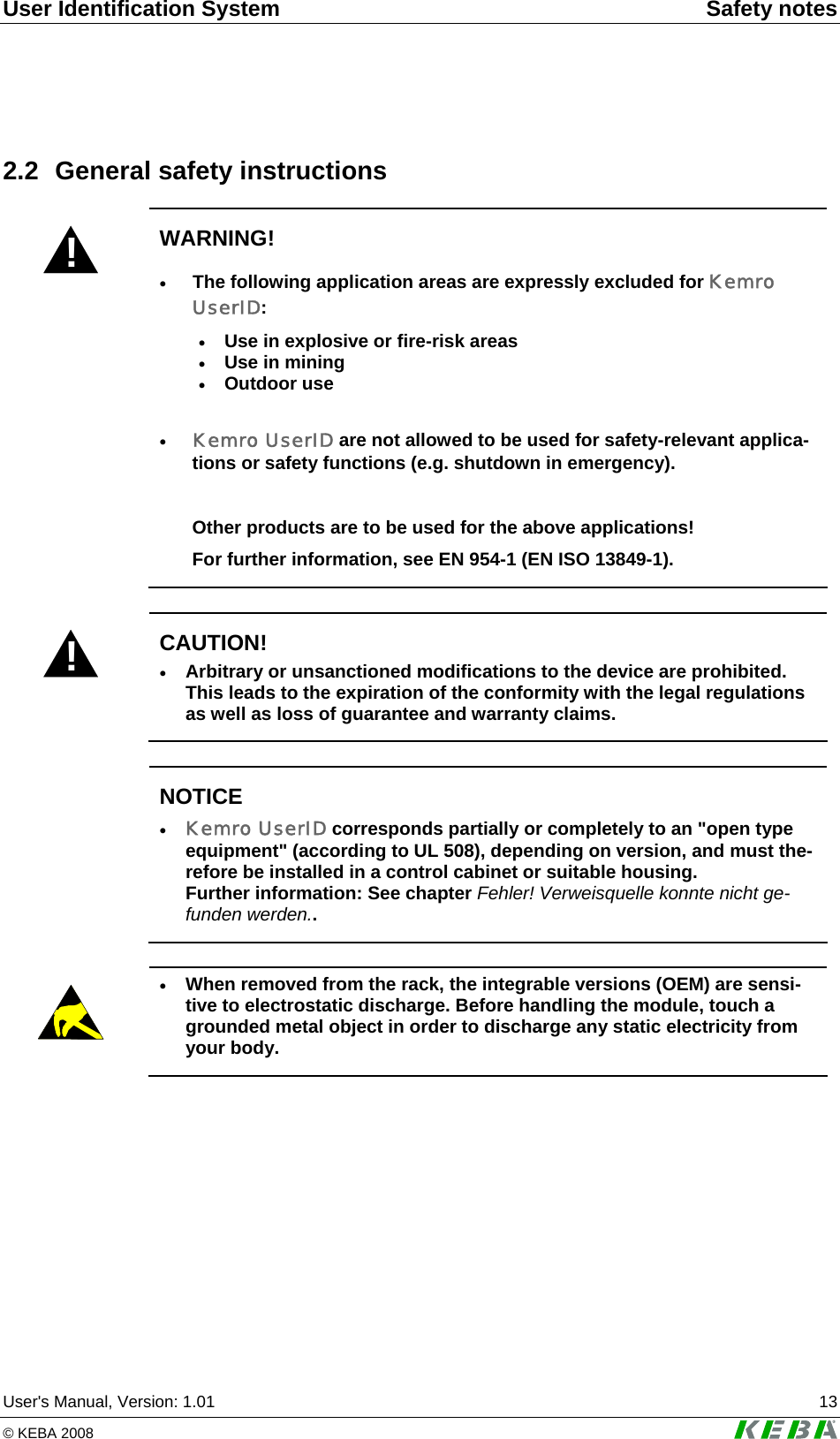
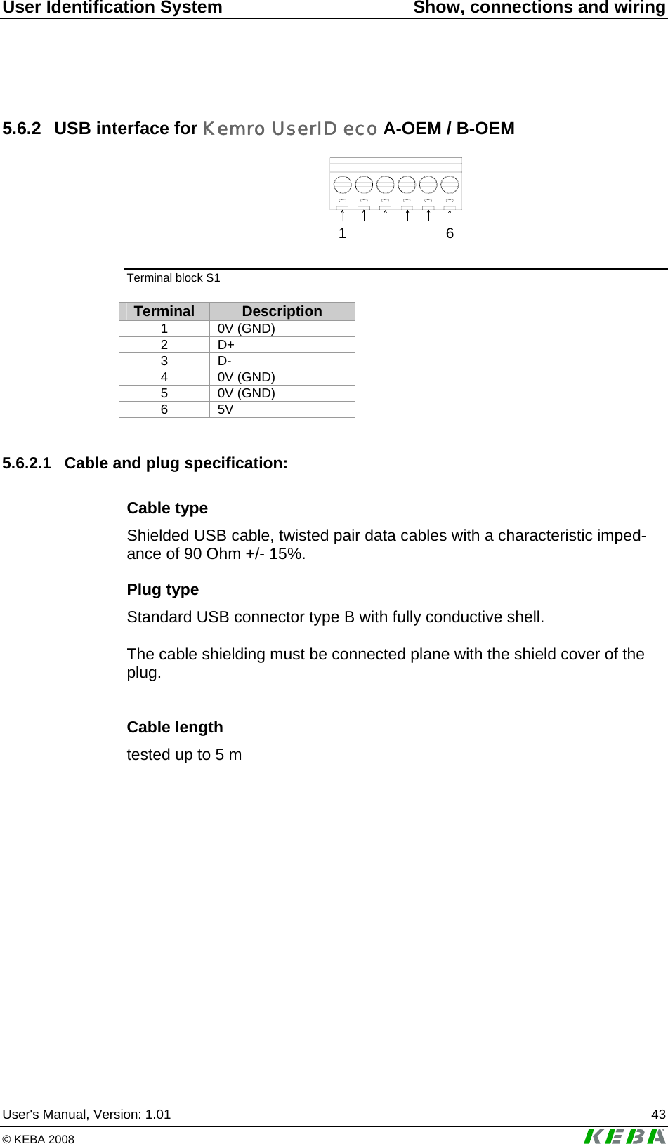
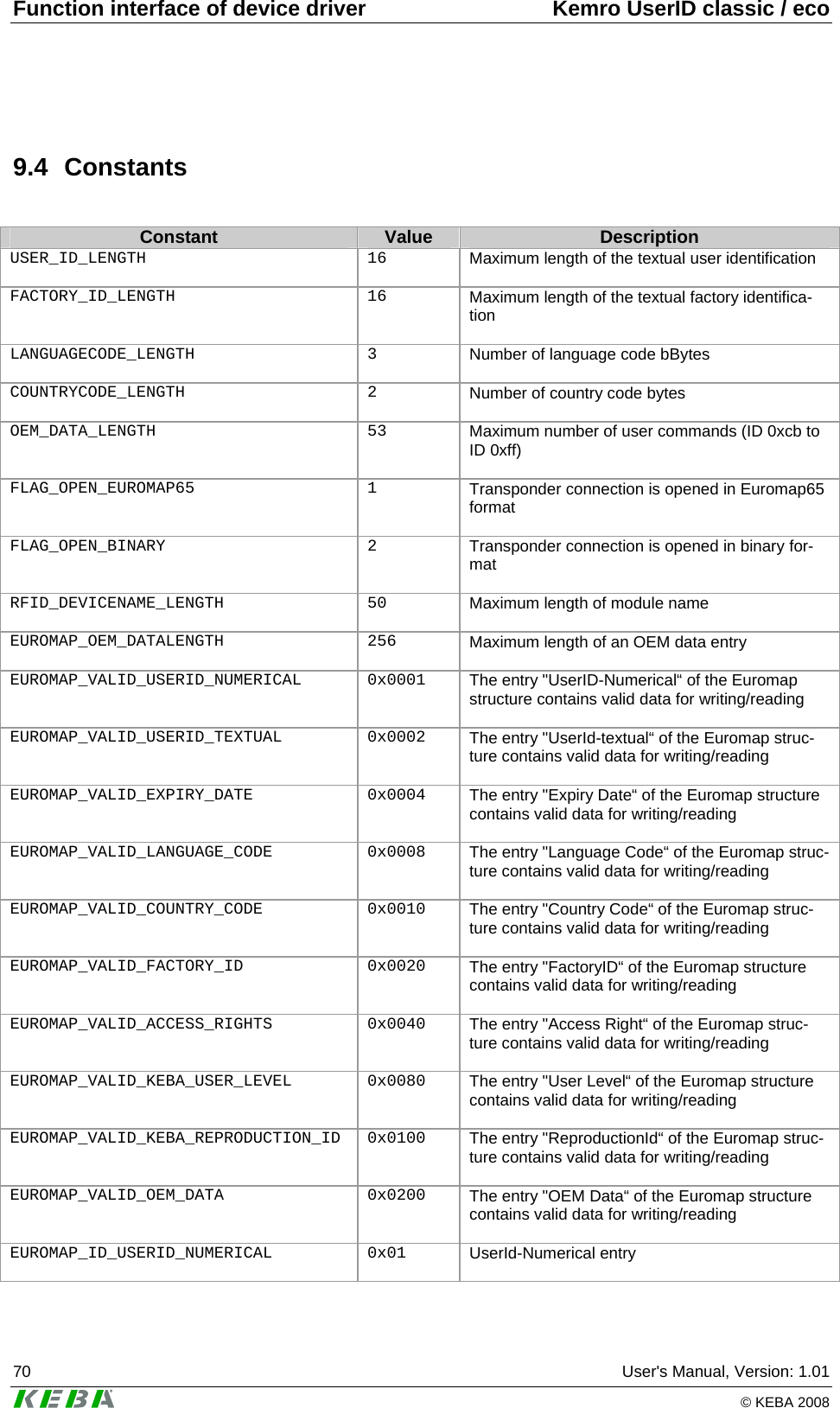
![Demo application Kemro UserID classic / eco 62 User's Manual, Version: 1.01 © KEBA 2008 Element Description Inventory cycle [ms] The cycle time with which the module searches for new transponders in the detection range (typical value: 50 ms). After the corresponding Change button is pressed this setting is changed. Safety key Key (32-bit safety key) for calculating the safety code acc. to the Euromap 65 standard. The safety code is calculated from the checksum of the data stored on the transponder and this safety key (hid-den factory safety key), and stored on trans-ponders in Euromap 65 format. After the corresponding Change button is pressed this setting is changed. LED off LED is switched off in the application mode LED on LED lights up in the application mode LED blink 1 Hz LED blinks once per second in the application mode LED blink 2 Hz LED blinks twice per second in the application mode Baud rate Transmission rate of serial interface. After the corresponding Change button is pressed this setting is changed. Usage of this mask z Displaying and changing the configuration of the Kemro UserID mo-dule](https://usermanual.wiki/KEBA/0005/User-Guide-937325-Page-62.png)
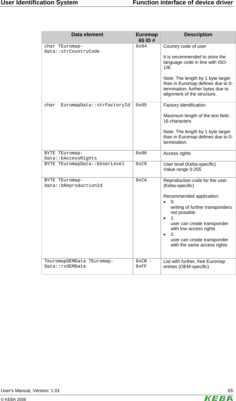
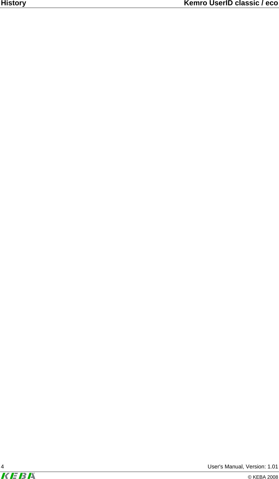
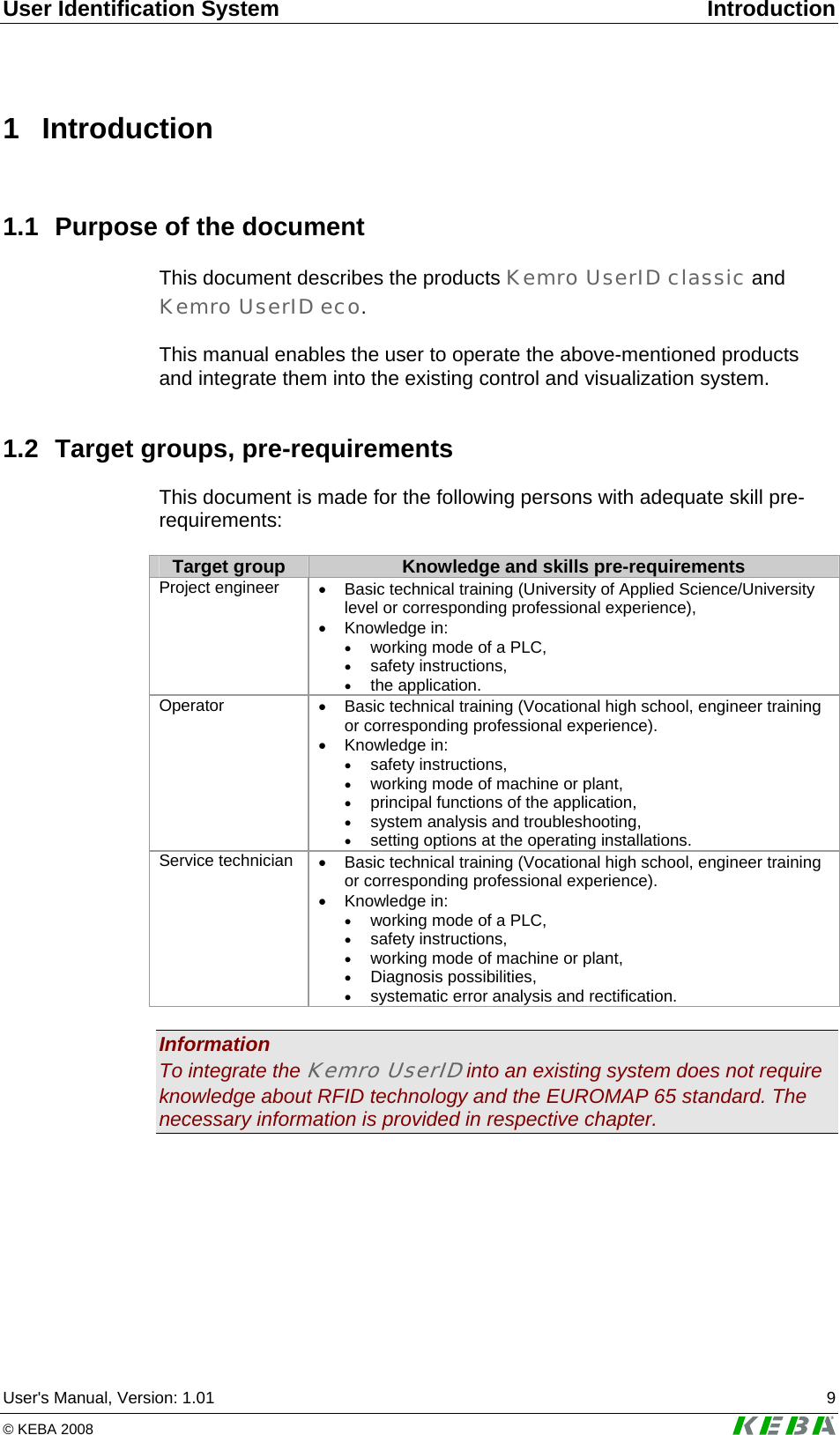
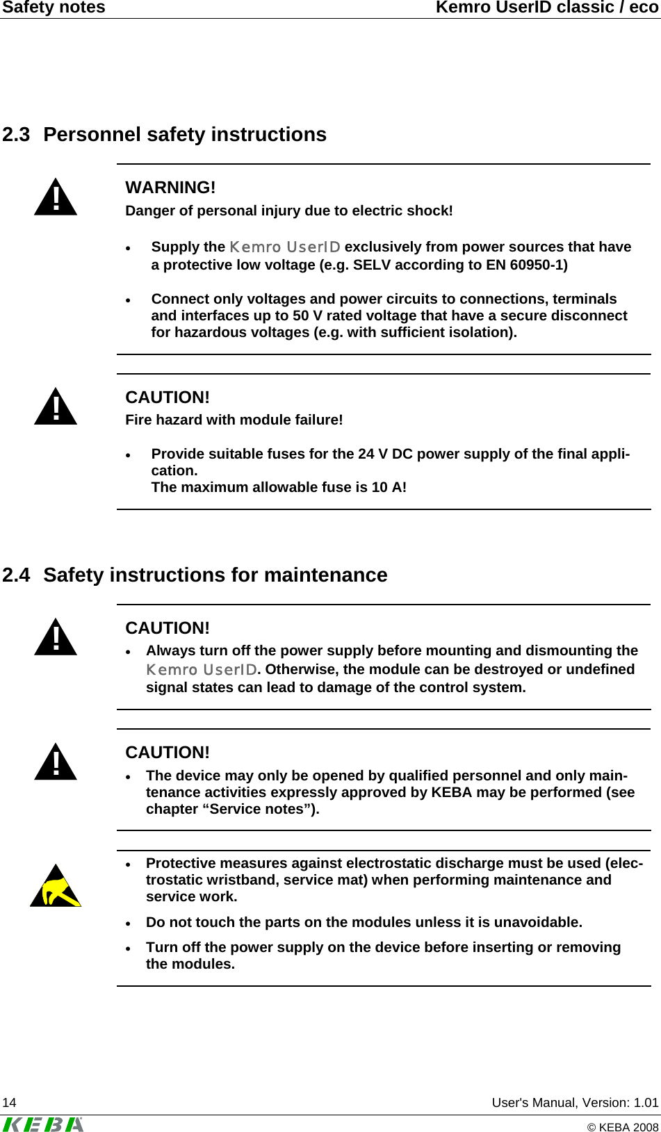
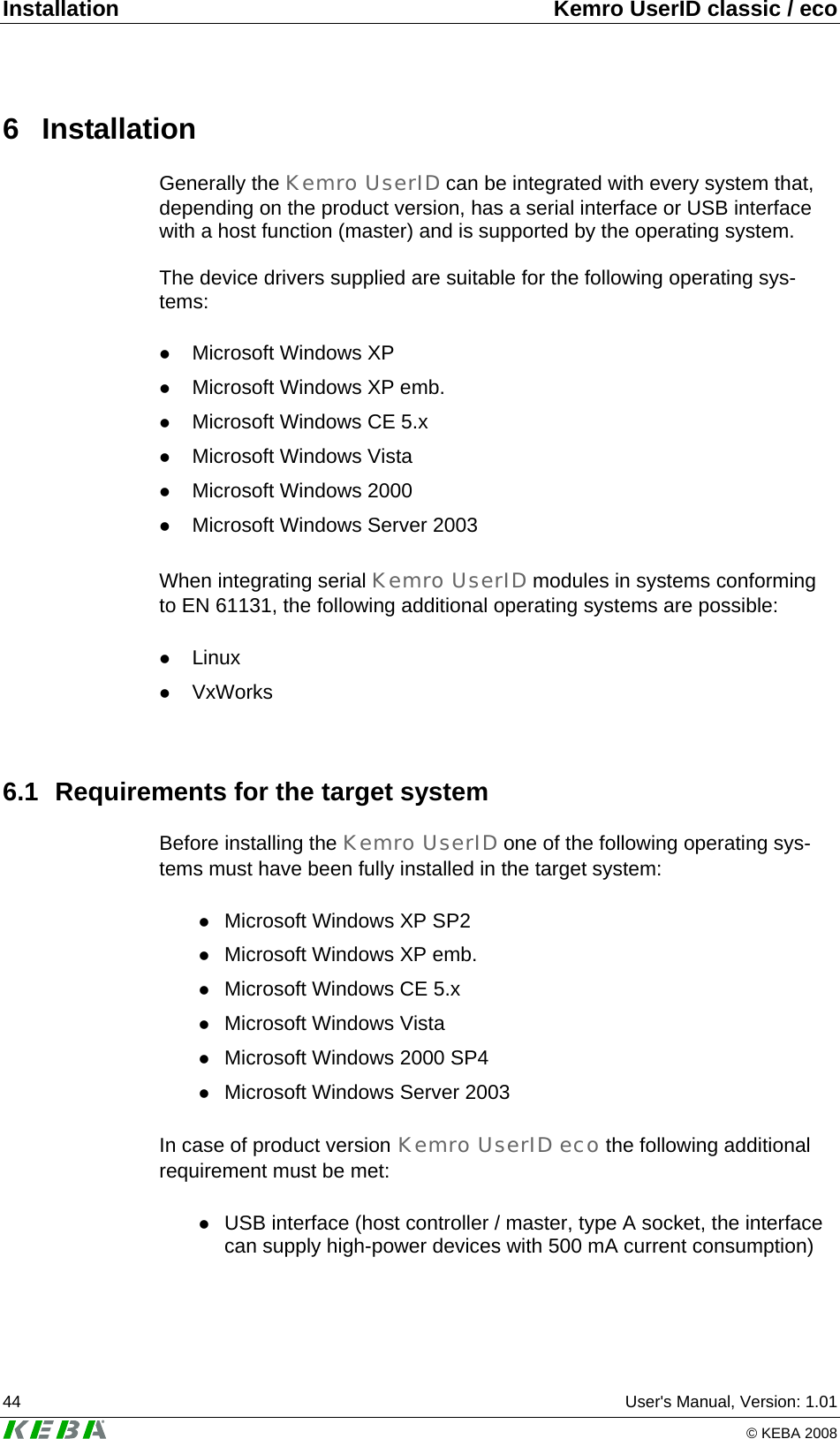
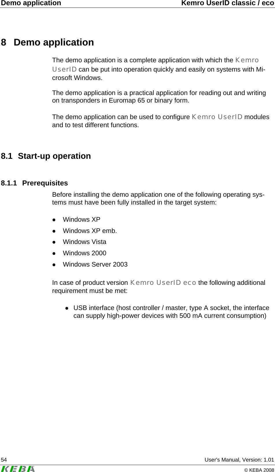
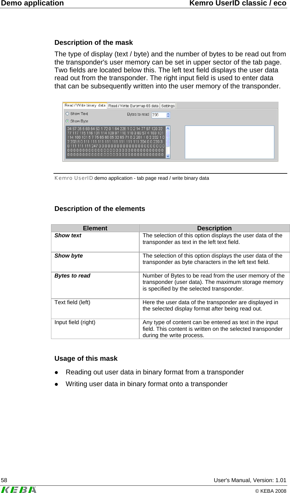
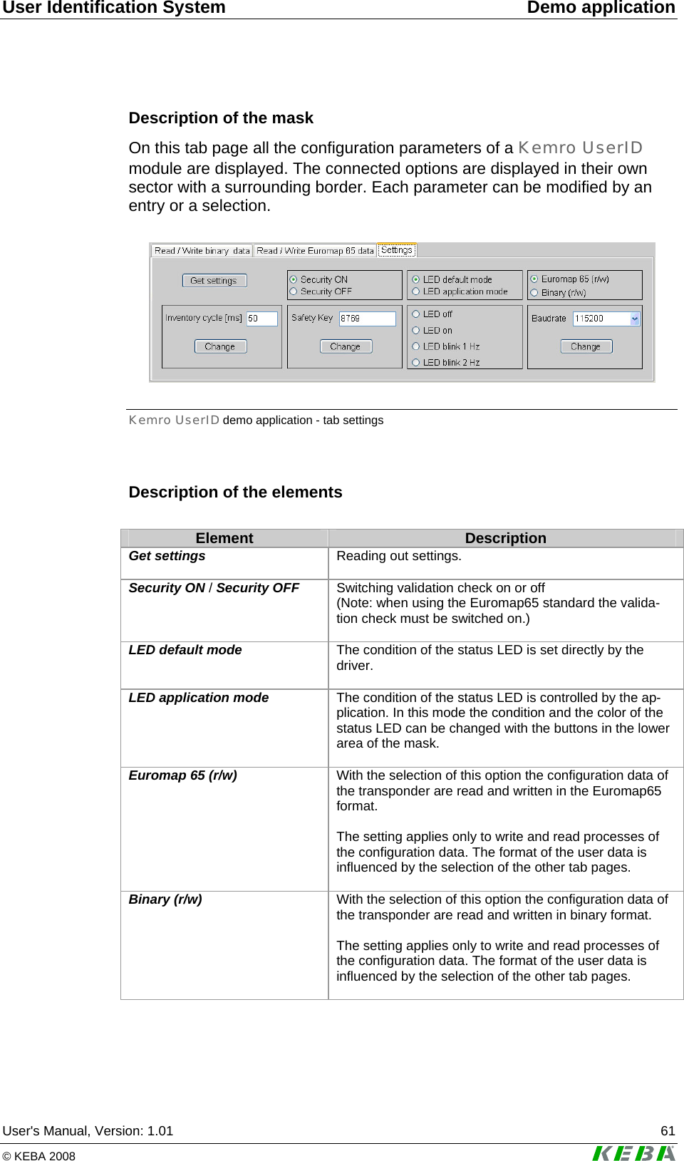
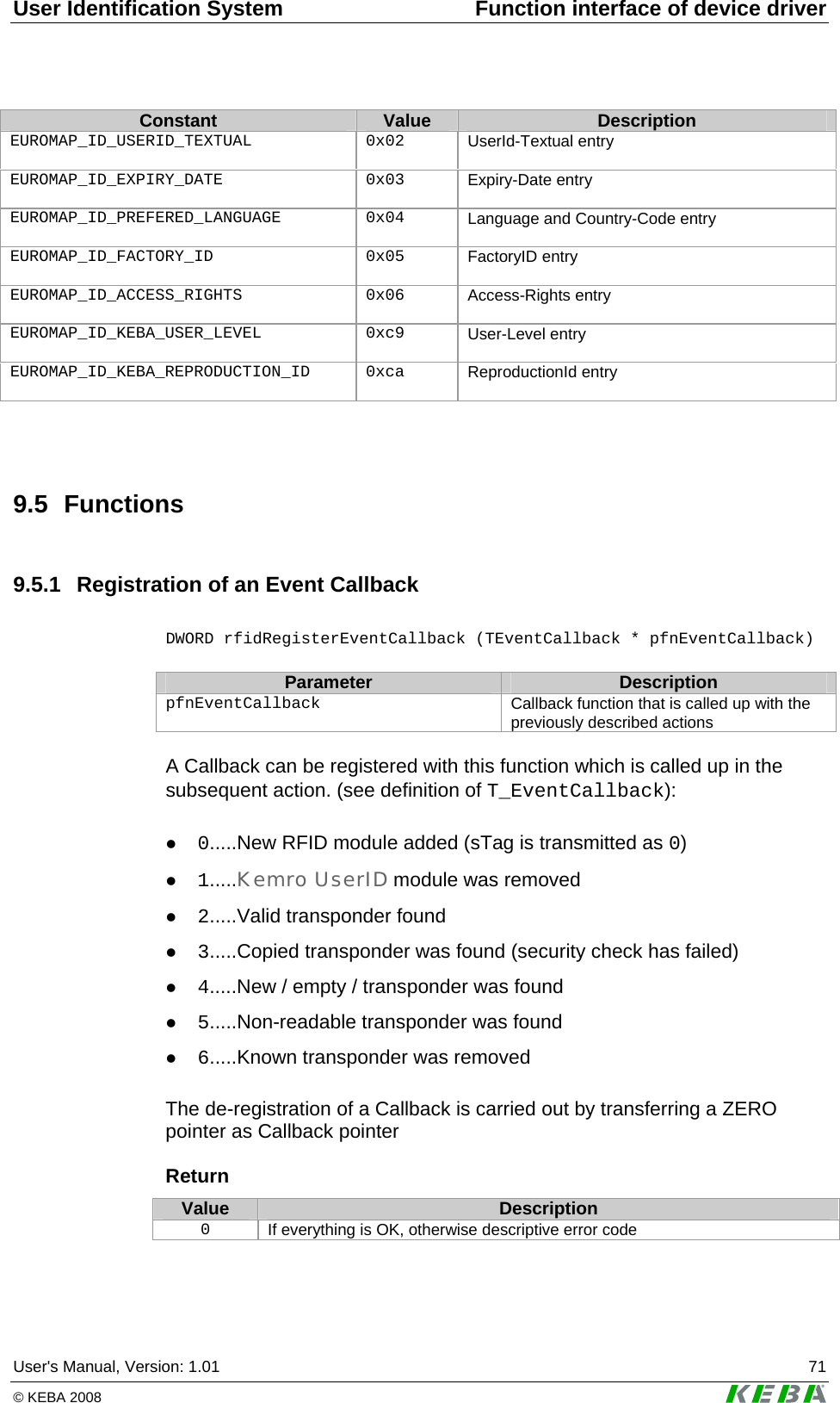
![Function interface of device driver Kemro UserID classic / eco 66 User's Manual, Version: 1.01 © KEBA 2008 9.2.2 Data structure TEuromapOEMData This data structure is used to specify further free Euromap65 entries in the Euromap65 format (ID 203-255). Data element Euromap 65 ID # Description BYTE TEuromapOEM-Data::bEuromapID 0x1F - 0xC8 Specific machine manufacturer parameters (these are issued exclusively by the EUROMAP organization, H1Hhttp://www.euromap.orgH ) BYTE TEuromapOEMData::bDummy -- Dummy for structure alignment WORD TEuromapOEMData::wLength -- Length of data of the Euromap65 entry defined by bEuromapID. BYTE TEuromapOEMData::rbEuromapData[EUROMAP_OEM_DATALENGTH] -- Data pointer of data of the Euro-map65 entry defined by bEuro-mapID. 9.2.3 Data structure TEuromapTime This data structure is used to display the Euromap65 time specifications. Data element Euromap 65 ID # Description WORD TEuromapTime::wYear -- Year BYTE TEuromapTime::bMonth -- Month (1-12) BYTE TEuromapTime::bDay -- Day (1-31) 9.2.4 Data structure TFactorySettings This data structure is used for reading the factory data of an RFID module. Data element Euromap 65 ID # Description DWORD TFactorySet-tings::dwSerialNumber -- Serial number of the RFID module](https://usermanual.wiki/KEBA/0005/User-Guide-937325-Page-66.png)
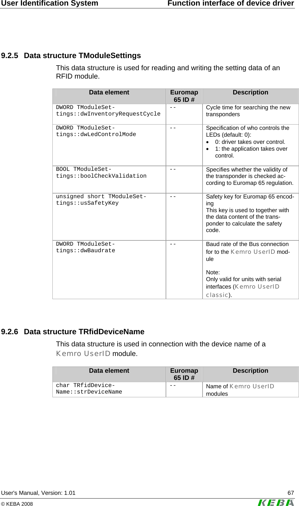
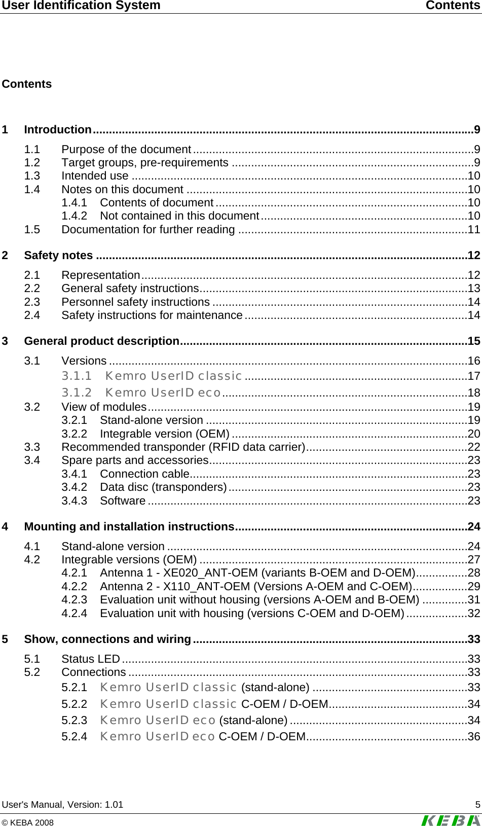
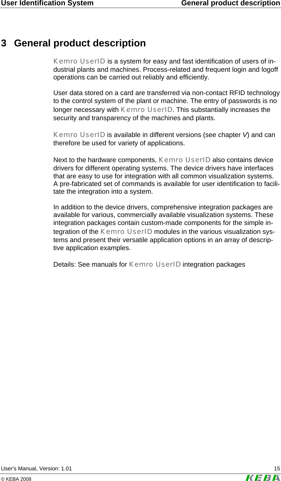
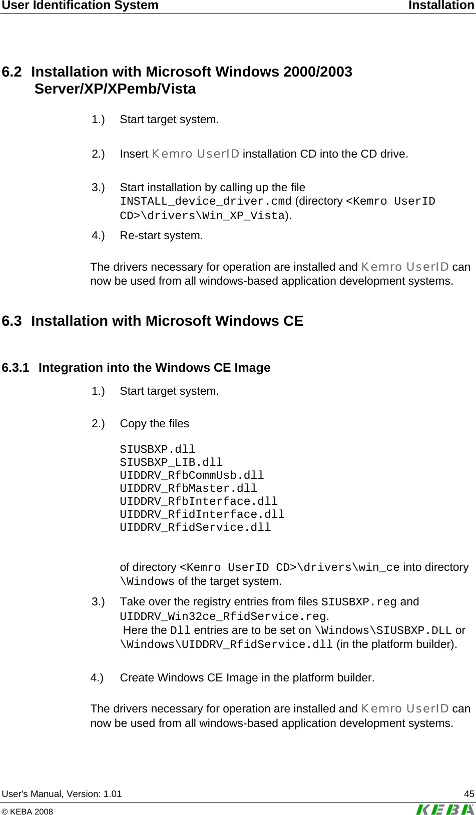
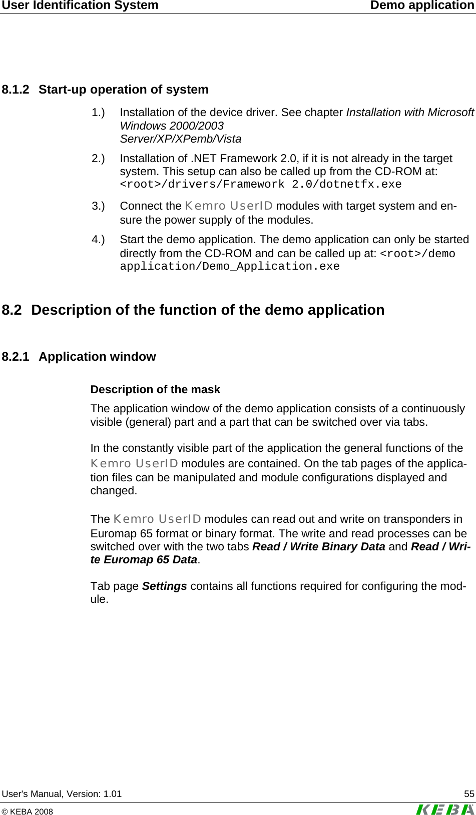
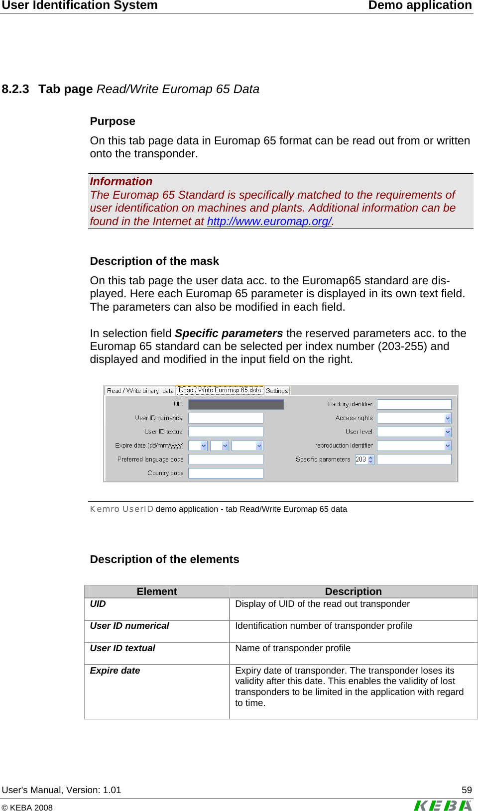
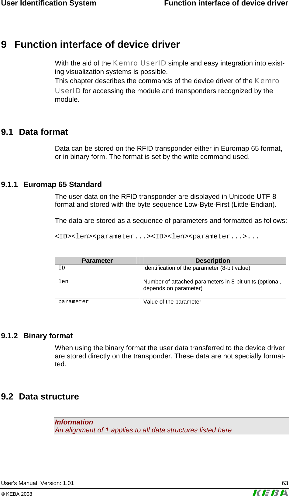
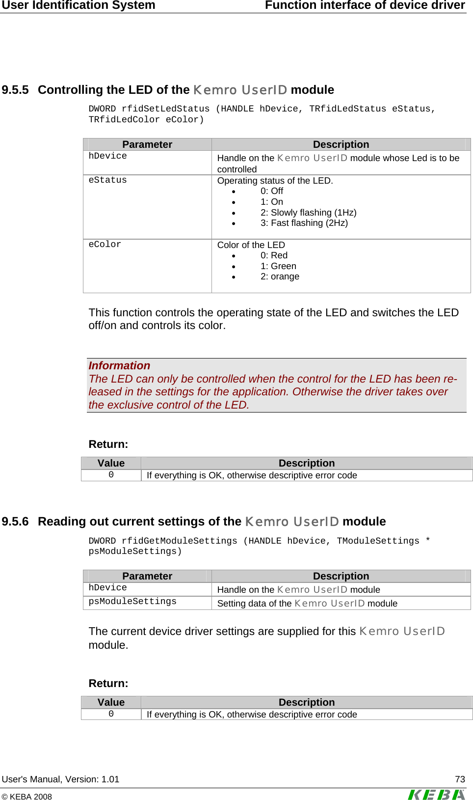
![Function interface of device driver Kemro UserID classic / eco 72 User's Manual, Version: 1.01 © KEBA 2008 9.5.2 Read out list of currently connected Kemro UserID modules DWORD rfidGetDeviceList (TRfidDeviceName rsDeviceName[], DWORD * pdwCount) Parameter Description rsDeviceName String list in which the automatically generated symbolic names of the Kemro UserID modules are written pdwCount In Length of string list Out: Number of entered RFID modules This function lists all Kemro UserID modules found (independent of con-nection, USB or RS232). The symbolic names specified are generated automatically and can continue to be used to open a Kemro UserID module with rfidOpenDevice, to control LEDs or to read or modify the settings of the module. Return Value Description 0 If everything is OK, otherwise descriptive error code 9.5.3 Opening a connection to a Kemro UserID module DWORD rfidOpenDevice (const TRfidDeviceName sDeviceName, HANDLE * phDevice) Parameter Description sDeviceName Symbolic name of Kemro UserID module to be opened phDevice Pointer on the Handle of the opened Kemro UserID mod-ule This function opens the data connection to a Kemro UserID module and supplies a Handle with which the data of the Kemro UserID module can continue to be accessed. Return: Value Description 0 If everything is OK, otherwise descriptive error code 9.5.4 Closing a connection to an opened Kemro UserID module void rfidCloseDevice (HANDLE hDevice) Parameter Description hDevice Name of the opened Kemro UserID module](https://usermanual.wiki/KEBA/0005/User-Guide-937325-Page-72.png)
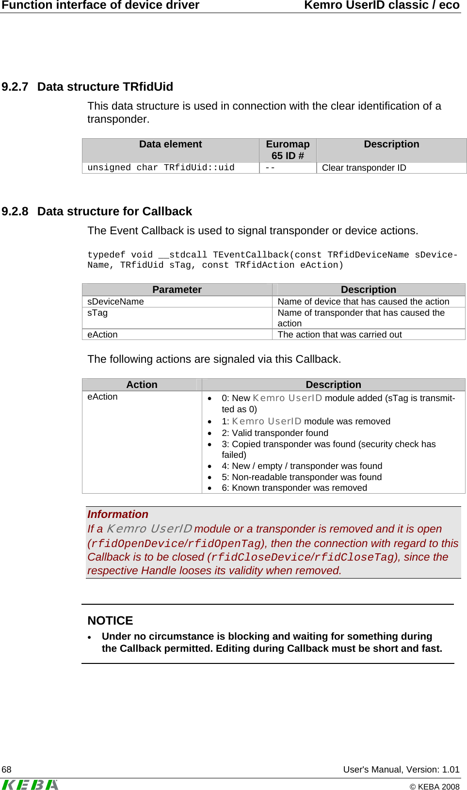
![Function interface of device driver Kemro UserID classic / eco 74 User's Manual, Version: 1.01 © KEBA 2008 9.5.7 New settings for the Kemro UserID module DWORD rfidSetModuleSettings (HANDLE hDevice, TModuleSettings * psModuleSettings) Parameter Description hDevice Handle on the Kemro UserID module psModuleSettings New setting data of the Kemro UserID module The current device driver settings are set for this Kemro UserID module. Return: Value Description 0 If everything is OK, otherwise descriptive error code 9.5.8 Reading out the factory settings of the Kemro UserID module DWORD rfidGetFactorySettings (HANDLE hDevice, TFactorySettings * psFactorySettings) Parameter Description hDevice Handle on the Kemro UserID module psFactorySettings Factory data of the Kemro UserID module The Kemro UserID module data entered at the factory are read out and supplied. Return: Value Description 0 If everything is OK, otherwise descriptive error code 9.5.9 Creating a list of currently recognized transponders DWORD rfidGetTagList (HANDLE hDevice, TRfidUid rsUids[], DWORD * pdwCount) Parameter Description hDevice Handle on the Kemro UserID module whose transponder is to be determined rsUids List into which the UIDs of the detected transponders are written pdwCount In: Length of UID list. Out: Number of entered transponders This function lists all detected transponders for the specified Kemro UserID module. The UIDs are required to establish a data connection to a transponder (rfidOpenTag).](https://usermanual.wiki/KEBA/0005/User-Guide-937325-Page-74.png)
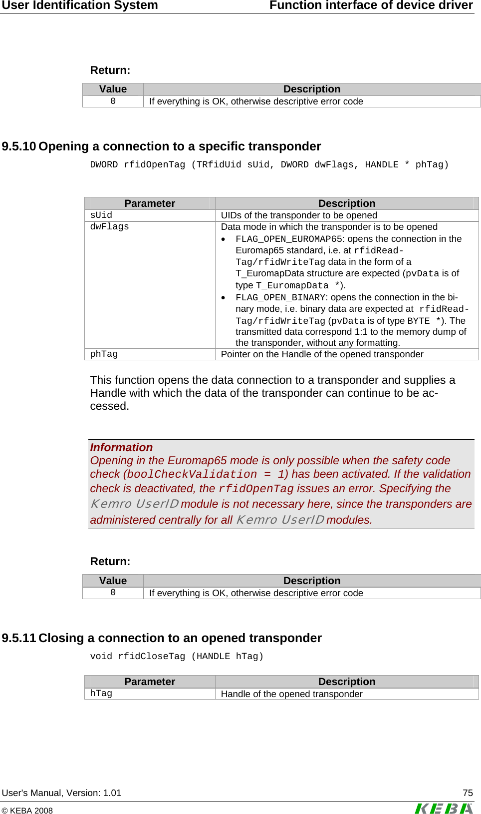
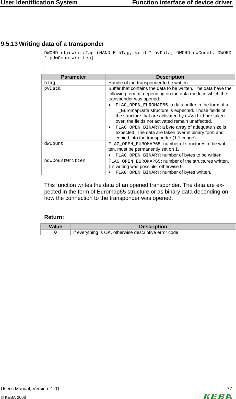
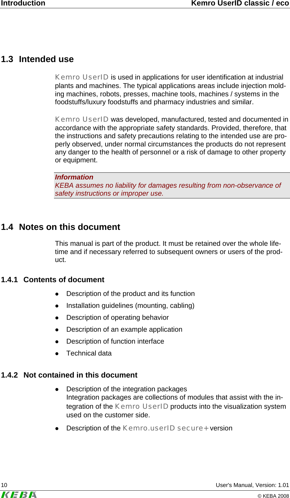
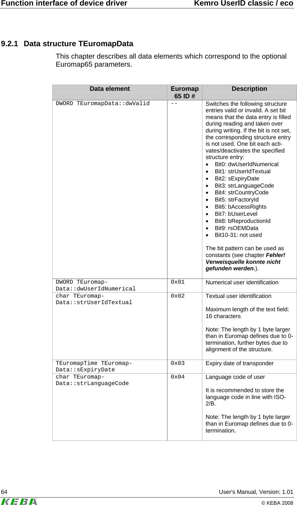
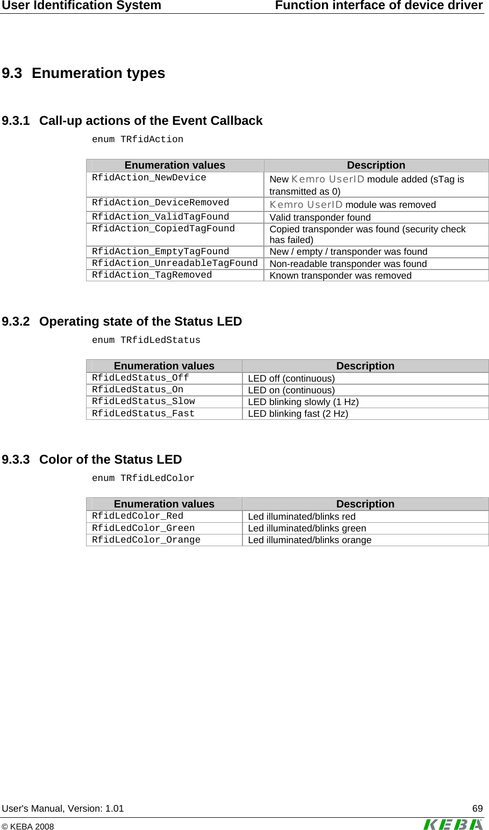
![Function interface of device driver Kemro UserID classic / eco 76 User's Manual, Version: 1.01 © KEBA 2008 9.5.12 Reading out data from a transponder DWORD rfidReadTag (HANDLE hTag, void * pvData, DWORD dwCount, DWORD * pdwCountRead) Parameter Description hTag Handle of the transponder to be read pvData Buffer for the data read out. The data have the following format, depending on the data mode in which the trans-ponder was opened: • FLAG_OPEN_EUROMAP65: a data buffer in the form of a T_EuromapData structure is expected. Those fields of the structure that are activated by dwValid (at parame-ter transfer [in]), are filled during reading out, the fields not activated remain unaffected. • FLAG_OPEN_BINARY: a byte array of adequate size is expected. The data are copied from the transponder into the buffer in binary form (1:1 image) dwCount FLAG_OPEN_EUROMAP65: number of structures to be read, must be permanently set on 1. • FLAG_OPEN_BINARY: number of bytes to be read. pdwCountRead FLAG_OPEN_EUROMAP65: number of the structures read, 1 if reading was possible, otherwise 0. • FLAG_OPEN_BINARY: number of bytes read. This function reads the data of an opened transponder. The data are sup-plied in the form of Euromap65 structure or as binary data depending on how the connection to the transponder was opened. Return: Value Description 0 If everything is OK, otherwise descriptive error code](https://usermanual.wiki/KEBA/0005/User-Guide-937325-Page-76.png)