Integrators manual

RFID UNI Module Introduction
Module Device
RFID UNI Module
Internal Technical Documentation V 1.0

Introduction
List of changes
Version
changed
from / to
Date Description Modified
by
0.1 11-2017 Created rter
0.2 01-2018 Document finished rter
1.0 01-2018 Review hpf/ltc

RFID UNI Module Introduction
Contents
1 Introduction ................................................................................................................... 5
1.1 Purpose of the document ..................................................................................... 5
1.2 Audience and prerequisites ................................................................................. 5
1.3 Intended use ........................................................................................................ 5
1.4 Notes on this document ....................................................................................... 6
1.4.1 Contents of document .............................................................................. 6
1.4.2 Not contained in this document ................................................................ 6
1.5 Documentation for further reading ....................................................................... 7
2 Safety notes .................................................................................................................. 8
2.1 Representation .................................................................................................... 8
3 Product overview .......................................................................................................... 9
3.1 Summary ............................................................................................................. 9
3.1.1 Range and detection .............................................................................. 10
3.2 RFID module before installation ......................................................................... 10
3.3 RFID module after installation ............................................................................ 11
3.3.1 AP CC300 operating panel (example) .................................................... 11
3.3.2 AP C3 operating panel (example) ........................................................... 12
4 Assembly and installation notes ................................................................................ 13
5 Connections and wiring ............................................................................................. 14
5.1 EMC and wiring guidelines ................................................................................ 14
5.1.1 Personal safety and exposure ................................................................ 14
5.1.2 Why EMC-aware wiring? ........................................................................ 14
5.1.3 Which EMC measures must be taken? ................................................... 14
5.2 Power supply ..................................................................................................... 15
5.3 Module interfaces .............................................................................................. 16
5.3.1 Assembly ............................................................................................... 16
5.3.2 Connector A ........................................................................................... 17
5.3.3 Connector B (optional) ........................................................................... 17
5.3.4 Connector C (optional) ........................................................................... 17
5.3.5 Dual LED (optional) ................................................................................ 17
5.4 Cables ............................................................................................................... 18
5.4.1 Connector cable for RFID module .......................................................... 18
6 Status LED (optional) .................................................................................................. 19
6.1 RFID status LED ................................................................................................ 19
7 Maintenance and repair notes .................................................................................... 20
7.1 Maintenance ...................................................................................................... 20
7.2 Repair ................................................................................................................ 20
7.2.1 Packaging and shipping ......................................................................... 20
7.3 Waste disposal .................................................................................................. 20

Introduction
8 Accessories and spares ............................................................................................. 21
9 Technical specification ............................................................................................... 22
10 Relevant EC directives and applicable standards .................................................... 23
10.1 EU directives ..................................................................................................... 23
10.2 Standards .......................................................................................................... 23
10.2.1 Validating conformance ........................................................................ 23
10.2.2 Other standards .................................................................................... 23
10.2.3 FCC statement (USA) ........................................................................... 23
10.2.4 RSS/CNR statement (Canada) ............................................................. 24

RFID UNI Module Introduction
1 Introduction
1.1 Purpose of the document
This planning manual describes the RFID UNI module, which is already
permanently installed in different KEBA products like operating panels and
teaching units. The application and functionality of the RFID module is the
same for each KEBA product.
1.2 Audience and prerequisites
The planning manual is geared towards those who are using or intend to
deploy an KEBA product with RFID module.
Only electrical technicians who are qualified to the VDE 1000-10 standard
are permitted to install and maintain.
This means personnel who:
can evaluate the work to be carried out and recognise the possible
hazards based on their technical training, knowledge and experience
plus their expertise in the applicable standards.
have a level of knowledge equivalent to that obtained through
professional training as a result of several years experience working in
a similar field.
1.3 Intended use
The intended use of the RFID UNI module includes deployment in KEBA
products.
The RFID UNI module (Radio Frequency Identification) is used in
conjunction with an RFID card for contactless logon and logoff (as per
ISO 15693) and is employed for user identification. This replaces the login
of a user with username and password.
The RFID UNI module may not be used to fulfil protection requirements in
the area of personal safety to prevent a malfunction compromising personal
safety.

Introduction
1.4 Notes on this document
1.4.1 Contents of document
RFID module description
Assembly and installation notes
Description of the connections and wiring including EMC measures
Description of the configuration
Description of the optional status LED
Maintenance notes
Accessories
Technical specification
1.4.2 Not contained in this document
Operating panel description
Teaching pendants description
Other KEBA products

RFID UNI Module Introduction
1.5 Documentation for further reading
The following is a listing of manuals for operating panels, which are
equipped with an RFID module:
Doc. No.: Planning
manual Description
1008790 AP CC300 operating device Describes the installation, assembly,
connection and operation of the
operating panel.
- in preparation - AP C3 operating device
Safety notes
2 Safety notes
2.1 Representation
At various points in this manual you will see notes and precautionary warn-
ings regarding possible hazards. The symbols used have the following
meaning:
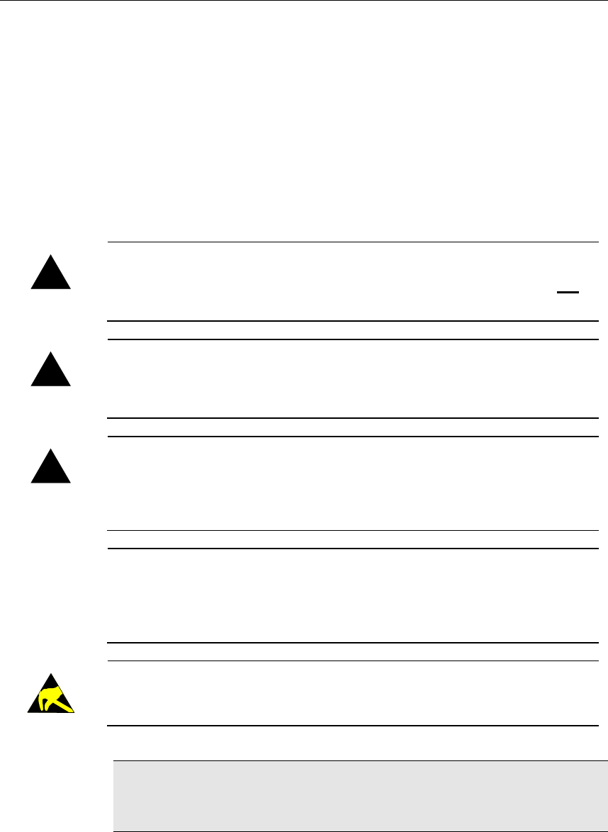
!
DANGER!
• indicates an imminently hazardous situation which, if not avoided, will
result in death or serious injury.
!
WARNING!
• indicates a potentially hazardous situation which, if not avoided, could
result in death or serious injury.
!
CAUTION!
• means that if the corresponding safety measures are not taken a poten-
tially hazardous situation can occur which, if not avoided, may result in
property damage or slight bodily injury.
NOTICE
• NOTICE used without the safety alert symbol indicates a potentially
hazardous situation which, if not avoided, may result in property dam-
age.
•
This symbol reminds you of the possible consequences of touching
electrostatically sensitive components.
Information
Informations on use of equipment and useful practical tips are identified by
the symbol "Information". "Information" do not contain any information that
draws attention to potentially dangerous or harmful functions.
RFID UNI Module Product overview
3 Product overview
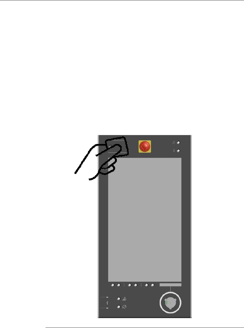
3.1 Summary
The RFID card user must hold the RFID card close to the RFID antenna on
the front of the operating panel for identification. The area of the RFID an-
tenna is indicated by two horizontal lines on the panel.
An RFID system comprises:
• RFID card
• RFID UNI module, installed in the device.
Contactless user identification with an RFID card (e.g. operating panel AP CC300)
Product overview
3.1.1 Range and detection
The typical range for RFID card to RFID UNI module is about 40 mm for the
recommended RI-I02112A-03 RFID card.
There is no provision to detect multiple cards at the same time. If several
RFID cards are within range, either only one will be detected or this will
cause a detection error.
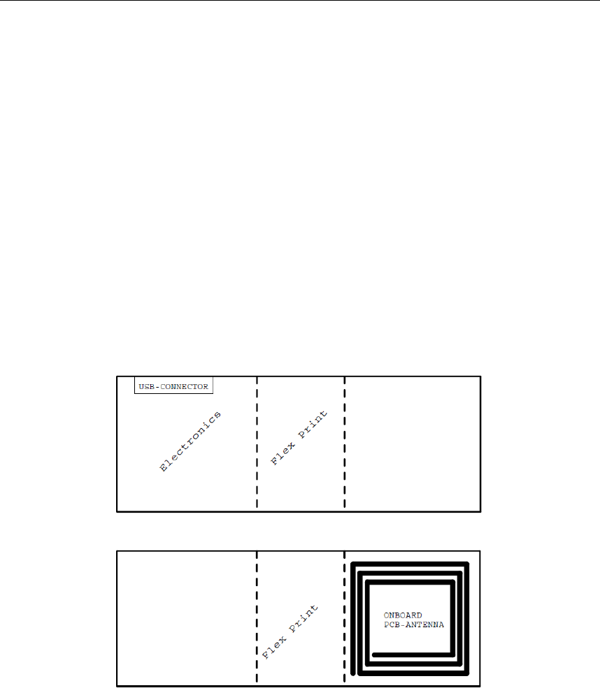
3.2 RFID module before installation
The illustrations below show the standard module with an USB connector.
The flexible part of the module allows a folded installation. The lateral, rigid
parts are then parallel to each other; a few millimeters apart (see chapter
3.3.2.)
Top view:
Bottom view:
RFID UNI Module Product overview
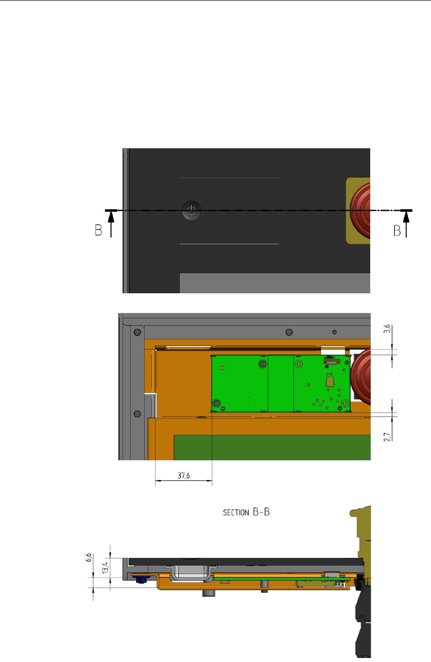
3.3 RFID module after installation
The following illustrations show the position of the module in stationary op-
erating panels.
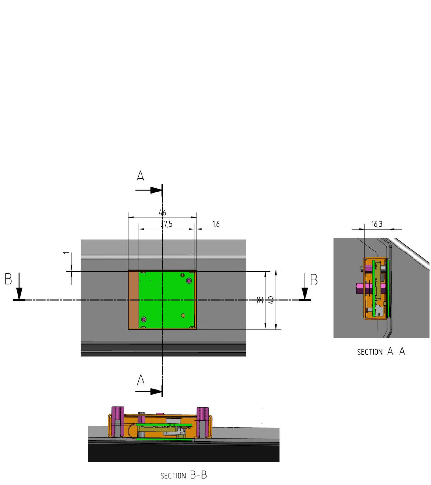
3.3.1 AP CC300 operating panel (example)
Front view:
Front view (without elements located in front of the module):
Section B view:
Product overview
3.3.2 AP C3 operating panel (example)
The RFID module is installed folded.
The first illustration shows the user-facing side of the module.
The second and third figures make the folded module easier to recognize;
two printed circuit boards and a flexible print in between.
Top View:

RFID UNI Module Assembly and installation notes
4 Assembly and installation notes
To guarantee the specified antenna range the minimum clearance between
antenna and base material (e.g. aluminium) must be respected.
Suitable precautions must be taken to prevent any cables located behind
the antenna from causing antenna detuning, e.g. providing a cover.

Connections and wiring
5 Connections and wiring
5.1 EMC and wiring guidelines
5.1.1 Personal safety and exposure
Safety extra-low voltage
All products are powered by safety extra-low voltage.
Magnetic field strength (distance of 20 cm)
The reference value at 13.56 MHz for H-Field: 73 mA/m
Result module unfolded (max.): 6.8 mA/m
Result module folded (max.): 6.7 mA/m
All levels are far below the applicable limit.
5.1.2 Why EMC-aware wiring?
The immunity of an electrical system depends essentially on wiring and
shielding that is designed to overcome any EMC problems. Servicing
experience has shown that inadequate wiring and shielding is a common
cause of system interference and failure.
Electromagnetic interference is far more troublesome than "conventional"
faults:
It is not normally recognised as such from the symptoms displayed and
can often be mistaken for a fault in an assembly, which is basically
sound.
They mainly occur sporadically and are difficult to duplicate.
As a consequence fault-finding is time-consuming and expensive.
Therefore ensure from the start that the wiring and shielding
conforms to the guidelines documented below.
5.1.3 Which EMC measures must be taken?
The EMC measures for the RFID UNI module concentrate on shielding the
connecting cable of the module.

RFID UNI Module Connections and wiring
5.2 Power supply
The power to the RFID module is supplied via the connectors for
communication.
The high-frequency area has its own voltage regulator.
Connections and wiring
5.3 Module interfaces
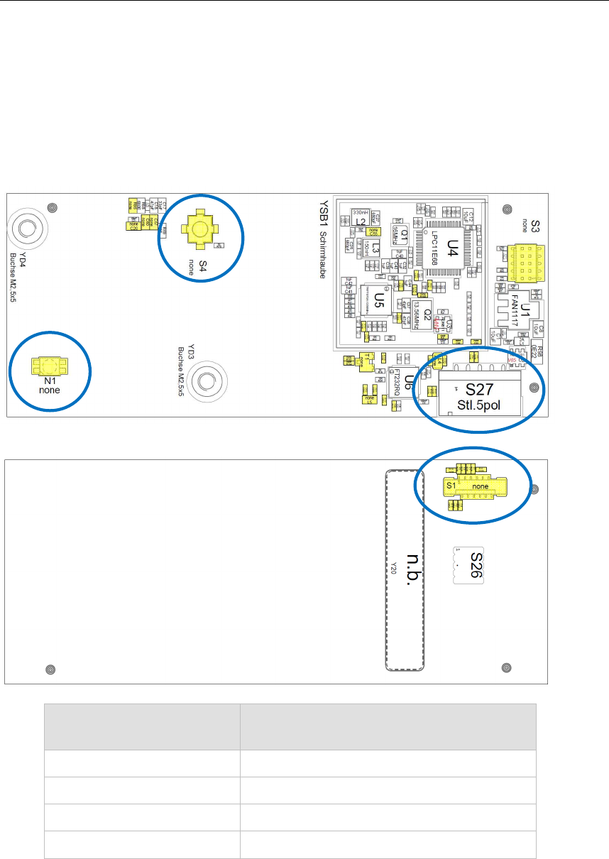
5.3.1 Assembly
Side A:
Side B:
Description Component No.
according to assembly diagram
Connector A S27
Connector B S1
Connector C S4
Dual LED N1
Connector A
C
onnector B
Connector
C
Dual LED

RFID UNI Module Connections and wiring
5.3.2 Connector A
This 5-pin connector is populated for USB communication.
5.3.3 Connector B (optional)
This 12-pin connector is populated on side B of the module. It enables USB
and serial communication.
5.3.4 Connector C (optional)
The coaxial connector can be populated optionally for using an external
antenna.
5.3.5 Dual LED (optional)
An dual led (red and green) can be populated to indicate the state of the
module.

Connections and wiring
5.4 Cables
5.4.1 Connector cable for RFID module
The connection cable for the RFID module must be shielded and no longer
than 3 m.

RFID UNI Module Status LED (optional)
6 Status LED (optional)
6.1 RFID status LED
The RFID status LED is located on the module and indicates the status of
RFID card recognition:
RFID status LED Meaning Cause of fault / solution
red RFID card not recognised or no
authorisation
RFID card is defective
Wrong information recorded
on RFID card
green for ca. 3
sec. RFID card has been recognised -
permanent red No firmware, hardware does not
boot
Contact the manufacturer
LED off Connection is OK -

Maintenance and repair notes
7 Maintenance and repair notes
7.1 Maintenance
This device does not require regular maintenance.
7.2 Repair
Only KEBA technicians may repair faulty devices, otherwise the warranty
becomes void.
7.2.1 Packaging and shipping
The module is placed in protective packing for shipping. Please return the
packaging since KEBA tries to reuse it to minimise the environmental
impact.
This protective packaging is not transport packaging and as such it is
unsuitable for transport by carrier or air. Suitable, extra transport packaging
must be used for this purpose.
7.3 Waste disposal
Comply with your national regulations for the disposal of electronic
components!

RFID UNI Module Accessories and spares
8 Accessories and spares
Component Order number
RFID UNI V1 AP_CC300 101719
RFID UNI V2 AP_C3 104242

Technical specification
9 Technical specification
General
Reading distance: 4 cm from the panel
Antenna installation: permanently installed
Positioning of RFID UNI module:
module can be located 5 mm from planes
Communication protocol:
according to ISO 15693
Signalling: 2-colour LED on the printed antenna (optional)
Interfaces
Data interface: serial
Supply voltage: 5 VDC (+/- 5%)
Connector plug: 5-pin / 12-pin (optional)
RF signal
Frequency response: 13.56 MHz
Transmission power: max. 200 mW
Sampling rate:
configurable (default: 10 samples / sec)
Dimensions
Module width: 38 mm
length: 92 mm
height: 7 mm
Environmental condition
Operating temperature: +5 °C to +55 °C
Storage temperature: -30 °C to +70 °C
Relative humidity: 5 to 95% (non-condensing)
Vibration resistance: as per IEC 61131
Shock resistance: as per IEC 61131

RFID UNI Module Relevant EC directives and applicable standards
10 Relevant EC directives and applicable standards
10.1 EU directives
2014/53/EU Radio Equipment Directive (RED)
10.2 Standards
The following non-legally binding European standards are used to validate
the RFID module's conformance to the directives.
10.2.1 Validating conformance
Personal safety: EN 50364:2010
Radio sector: EN 300330-2 V2.1.1
EMC sector: EN 301489-1 V2.1.1 / EN 301489-3 V1.6.1
Electrical safety: EN 60950-1:2006 + A2:2013
10.2.2 Other standards
In addition the following non-legally binding standards provide advice in
some areas:
Environmental conditions
EN 61131-2:2007 Programmable logic controller - part 2 Equipment requirements and tests
10.2.3 FCC statement (USA)
FCC Part 15 Radio Frequency Devices
The device complies with Part 15 of the FCC Rules. Operation is subject to
the following two conditions:
1. this device may not cause harmful interference, and
2. this device must accept any interference received, including in-
terference that may cause undesired operation.
This device is labelled with an FCC ID number.
If this label is not visible when installed in an end device, the outside of the
device MUST also display a label referring to the enclosed module.
e.g. "Contains FCC ID: U870008"
(KEBA Product RFID UNI Module)

Relevant EC directives and applicable standards
10.2.4 RSS/CNR statement (Canada)
This device complies with Industry Canada’s licence-exempt RSSs. Opera-
tion is subject to the following two conditions:
(1) This device may not cause interference; and
(2) This device must accept any interference, including interference that
may cause undesired operation of the device.
Le présent appareil est conforme aux CNR d’Industrie Canada applicables
aux appareils radio exempts de licence. L’exploitation est autorisée aux
deux conditions suivantes:
(1) l’appareil ne doit pas produire de brouillage;
(2) l’utilisateur de l’appareil doit accepter tout brouillage radioélectrique
subi, même si le brouillage est susceptible d’en compromettre le fonc
tionnement.
This device is labelled with an IC identification number.
If this label is not visible when installed in an end device, the outside of the
device MUST also display a label referring to the enclosed module.
e.g. "IC: 20800-RFIDUNI"
(KEBA Product RFID UNI Module)
Information
Changes or modifications not expressly approved by KEBA could void the
user's authority to operate the equipment.