KENMORE Laundry Centers Manual 98010139
User Manual: KENMORE KENMORE Laundry Centers Manual KENMORE Laundry Centers Owner's Manual, KENMORE Laundry Centers installation guides
Open the PDF directly: View PDF ![]() .
.
Page Count: 9
SWAINS
Installation intructions
washer/dryer gas
SAVE THESE INSTRUCTIONS
P/N 131531800 (9511)
Before you begin...
Please read these instructions all the
way through.
er screwdriver
_e rs
_Socket Level
You need these tools to
Ainstall Kenmore
your
• Laundry Center. Get
them together in ,one place to keep
track of them.
Check the spot where you
B are going to install the
• Laundry Center. Proper
installation is your responsibility.
Make sure you have everything
necessary for proper installation.
You will need to meet State code/law
requirements: Some Codes keep from
or limit installation of clothes dryers
in residential garages, closets, mobile
homes and sleeping quarters. (Check
with your local building inspector and
ANSI Z 223.1--1988 National Fuel
Gas Code.) For mobile homes,
installation must conform to the
Manufactured Home Construction and
Safety Standard, Title 2,* CFR, Part 32-
80 (formerly the Federal Standard tbr
Mobile Home Construction and Safety,
Title 24, HUD [Part 280], 1975).
Important: Observe all governing
codes and 0_dinances.
ATTENTION SERVICERS:
Wiring diagram is located behind the
dryer access panel.
Recommended location
Size: Must be large enough to fully
open dryer door. For recessed or closet
installations see Page 6 for spacing; for
product dimensions see the last page
of these instructions.
Support: The floor must be able to
support the appliance loaded weight of
500 pounds.
Level Floor: Maximum floor slope
under Laundry Center is 1 inch.
Protection from the weather:
Do not install or store appliance where
weather or dripping water will come
in contact with the appliance. Proper
operation of dryer cycles requires
temperatures above 45°F. As some
water remains in the washer, do not
store or operate the washer below 32 °F.
For storage below 32°F. see Use and
Care Guide for "Winterizing."
Mobile Home Use: The gas appliance
mu,;t be securely fastened to the floor.
Sears Kit No. 346764 is available at
your local Sears store or Sears Service
Center.
For your safety,
the information in this manual must
be followed to minimize the risk of
fire or explosion or to prevent
property damage, personal injury
or loss of life.
Do not store or use gasoline or
other flammable vapors and
liquids in the vicinity of this or
any other appliance.
• WHAT TO DO IF YOU
SMELL GAS
• Do not try to light any appliance.
• Do not touch any electrical
switch; do not use any phone in
your building.
• Clear the room, building or area
of all occupants.
•Immediately call your gas
supplier from a neighbor's
phone. Follow the gas supplier's
instructions.
• If you cannot reach your gas
supplier, call the fire department.
Installation and service must be
performed by a qualified installer,
service agency or the gas supplier.
• Never install the Laundry Center up
against draperies or curtains and be
sure to keep any and all items from
falling or collecting behind the
Laundry Center.
•Replace all access or service panels
before operating Laundry Center.
Electrical requirements
Electrical ground is required
on this appliance.
Recommended
grounding instructions
This appliance-must be grounded. In
the eve nt of malfimction or breakdown,
groun,:ling will reduce the risk of
electric shock by providing a path of
least resistance for electric current.
This appliance is equipped with a cord
having an equipment-grounding
conductor and a grounding plug. The
plug must be plugged into an
appropriate outlet that is properly
installed and grounded in accordance
with all local codes and ordinances.
_-"-_[_1_] hnproper connection
of the equiwng4at-grounding conductor
can result in a risk of electric shock.
Check with a qualified electrician or
serviceman if you are in doubt as to
whether the appliance is properly
grounded.
Do not modify the plug provided with
the appliance--if it will not fit the
outlet, have a proper outlet installed
by a cualified electrician.
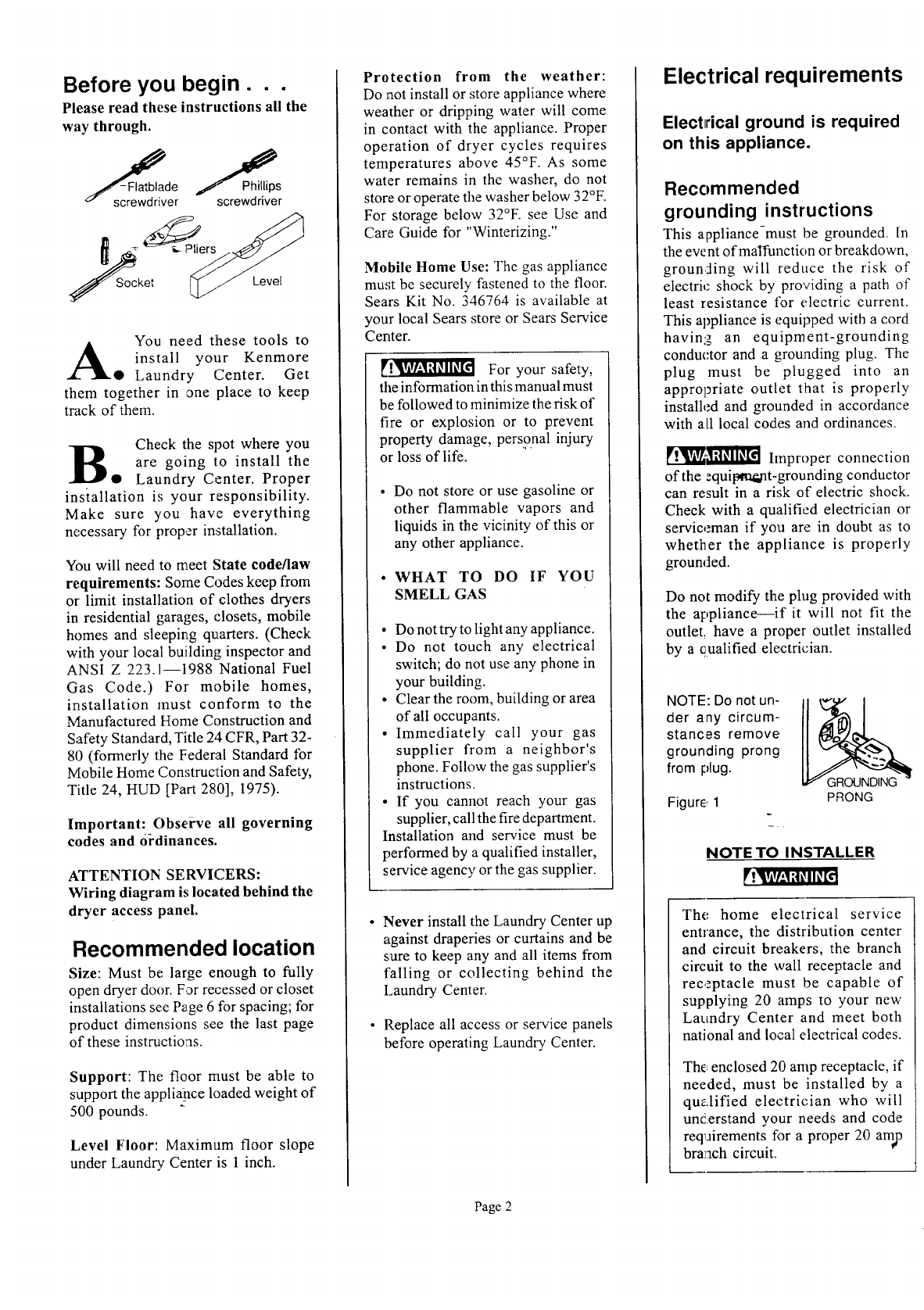
NOTE: Do not un-
der any circum-.
stances remove
grounding prong
from plug.
Figure, 1 PRONG
NOTE TO INSTALLER
The home electrical service
entrance, the distribution center
and circuit breakers, the branch
circuit to the wall receptacle and
receptacle must be capable of
supplying 20 amps to your new
Laundry Center and meet both
national and local electrical codes.
The enclosed 20 amp receptacle, if
needed, must be installed by a
qualified electrician who will
understand your needs and code
reqairements for a proper 20 amp
branch circuit.
Page 2
1. A 120 volt, 60 Hz, AC only
electrical supply is required on a
separate 20 ampere circuit fused by
a time delay fuse or ciircuit breaker.
2. A 3-prong grounded wall receptacle
(grounded in accordance with the
National Electrical Code, ANSI/
NFPA 70-1987, and local codes and
ordinances) is required.
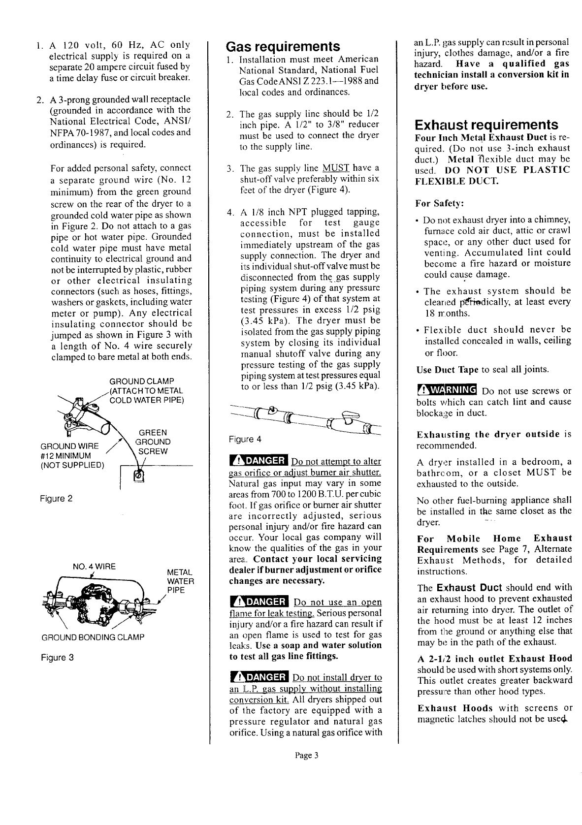
For added personal safety, connect
a separate ground wire (No. 12
minimum) from the green ground
screw on the rear of the dryer to a
grounded cold water pipe as shown
in Figure 2. Do not attach to a gas
pipe or hot water pipe. Grounded
cold water pipe must have metal
continuity to electrical ground and
not be interrupted by plastic, rubber
or other electrical insulating
connectors (such as hoses, fittings,
washers or gaskets, including water
meter or pump). Any electrical
insulating connector should be
jumped as shown in Figure 3 with
a length of No. 4 wire securely
clamped to bare metal at both ends.
GIqOUND CLAMP
/.(ATTACH TO METAL
OLD WATER PIPE)
"1_ - _ "\ GREEN
GROUND WIRE /_'_ ,_aROUND
.12M,NIMU \SgREW
(NOT SUPPLIED) ] [_,_
Figure 2
NO. 4 WIRE
METAL
WATER
PIPE
GROUND BONDING CLAMP
Figure 3
Gas requirements
1. Installation must meet American
National Standard, National Fuel
Gas CodeANSI Z 223.1--1988 and
local codes and ordinances.
2, "['he gas supply line should be 1/2
inch pipe. A l/2" to 3/8" reducer
must be used to connect the dryer
to the supply line.
3. The gas supply line MUST have a
shut-off valve preferably within six
feet of the dryer (Figure 4).
4, A 1/8 inch NPT plugged tapping,
accessible for test gauge
connection, must be installed
immediately upstream of the gas
supply connection. The dryer and
its individual shut-offvalve must be
disconnected from the .gas supply
piping system during any pressure
testing (Figure 4) of that system at
test pressures in excess 1/2 psig
(3.45 kPa). The dryer must be
isolated from the gas supply piping
system by closing its individual
manual shutoff valve during any
pressure testing of the gas supply
piping system at test pressures equal
to or less than 1/2 psig (3.45 kPa).
Figure 4
II?'!_ Do not attempt to alter
gas orifice or adjust burner air shutter.
Natural gas input may vary in some
areas from 700 to 1200 B.T.U. per cubic
foot. If gas orifice or burner air shutter
are incorrectly adjusted, serious
personal injury and/or fire hazard can
occur. Your local gas company will
know the qualities of the gas in your
area. Contact your local servicing
dealer if burner adjustment or orifice
changes are necessary.
llg_ Do not use an open
flame for leak testing. Serious personal
injury and/or a fire hazard can result if
an open flame is used to test for gas
leaks. Use a soap and water solution
to test all gas line fittings.
Do not install dryer to
an L.P. gas supply without installing
conversion kit. All dryers shipped out
of the factory are equipped with a
pressure regulator and natural gas
orifice. Using a natural gas orifice with
an L.R gas supply can result in personal
injury, clothes damage, and/or a fire
hazard. Have a qualified gas
technician install a conversion kit in
dryer before use.
Exhaust requirements
Four Inch Metal Exhaust Duct is re-
quired. (Do not use 3-inch exhaust
duct.) Metal "flexible duct may be
used. DO NOT USE PLASTIC
FLEXIBLE DUCT.
For Safety:
• Do not exhaust dryer into a chimney,
furnace cold air duct, attic or crawl
space, or any other duct used for
venting. Accurnulated lint could
become a fire hazard or moisture
could cause damage.
• The exhaust system should be
cleaned p_ri_dically, at least every
18 n:onths.
• Flexible duct should never be
installed concealed in walls, ceiling
or floor.
Use Duct Tape to seal all joints.
_l_]l!_[ Do not use screws or
bolts which can catch lint and cause
blockage in duct.
Exhausting the dryer outside is
recommended.
A dryer installed in a bedroom, a
bathrcom, or a closet MUST be
exhausted to the outside.
No other fuel-burning appliance shall
be installed in the same closet as the
dryer. -_
For Mobile Home Exhaust
Requirements see Page 7, Alternate
Exhaust Methods, for detailed
instructions.
The Exhaust Duct should end with
an exhaust hood to prevent exhausted
air returning into dryer. The outlet of
the hood must be at least 12 inches
from the ground or anything else that
may be in the path of the exhaust.
A 2-1/2 inch outlet Exhaust Hood
should be used with short systems only.
This outlet creates greater backward
pressure than other hood types.
Exhaust Hoods with screens or
magnetic latches should not be useqk
Page 3
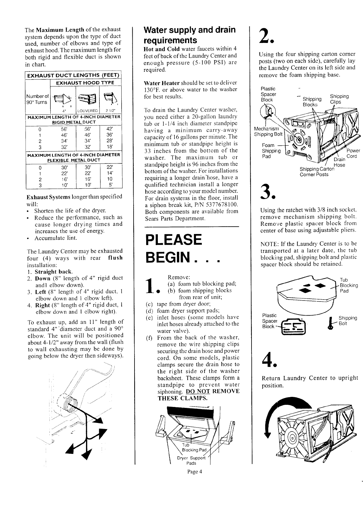
TheMaximumLength of the exhaust
system depends upon the type of duct
used, number of elbows and type of
exhaust hood. The maximum length for
both rigid and flexible duct is shown
in chart.
EXHAUST DUCT LENGTHS (FEET)
EXHAUST HOOD TYPE
-MAXIPfUPI LENGTH OF 4-INCH DIAMETER
RIGID METAL DUCT
0 56' !"_"5_- 7i_ 42' --
1 a6' ,46' 36'
2 34' :34' 28'
3 32' 32' J 18'
HAXIHUM LENGTH OF 4-INCH DIAHETER
FLEXIBLE HETAL DUCT
0 30' ' 30' 22'
1 22' 22' [ 14'
i
2 16' / 16' I 10
s
Exhaust Systems longer than specified
will:
•Shorten the life of tile dryer.
•Reduce the performance, such as
cause longer drying times and
increases the use of energy.
•Accumulate lint.
The Laundry. Center may be exhausted
four (4) ways with rear flush
installation:
1. Straight back.
2. Down (8" length of 4" rigid duct
andl elbow down).
3. Left (8" length of 4" rigid duct, 1
elbow down and 1 elbow left).
4. Right (8" length of 4" rigid duct, 1
elbow down arid 1 ,elbow right).
To exhaust up, add an 11" length of
standard 4"diameter duct and a 90 °
elbow. The unit will be positioned
about 4-1/2" away from the wall (flush
to wall exhausting may be done by
going below the dryer then sideways).
Water supply and drain
requirements
Hot and Cold water faucets within 4
feet of back of the Laundry Center and
enough pressure (5-100 PSI) are
required.
Water Heater should be set to deliver
", o
1._0 F. or above water to the washer
for best results.
To drain the Laundry Center washer,
you need either a 20-gallon laundry
tub or 1-1/4 inch diameter standpipe
having a minimum carry-away
capacity of 16 gallons per minute. The
minimum tub or standpipe height is
33 inches from the bottom of the
washer. The maximum tub or
standpipe height is 96 inches from the
bottom of the washer. For installations
requiring a longer drain'fiose, have a
qualified technician install a longer
hose according to your model number.
For drain systems in the floor, install
a siphon break kit, P/N 5377678100.
Both components are available from
Sears Parts Department.
PLEASE
BEGIN...
(c)
(d)
(e)
(0
Remove:
(a) foam tub blocking pad;
(b) foam shipping blocks
from rear of unit;
tape from dryer door;
foam dryer support pads;
inlet hoses (some models have
inlet hoses already attached to the
water valve).
From the back of the washer,
remove the wire shipping clips
securing the drain hose and power
cord. On some models, plastic
clamps secure the drain hose to
the right side of the washer
backsheet. These clamps form a
standpipe to prevent water
siphoning. DO NOT REMOVE
THESE CLAMPS.
Blocking Pac
Dryer Support
Pads
Page 4
Using the four shipping carton comer
posts (two on each side), carefully lay
the Laundry Center on its left side and
remove the foam shipping base.
Plastic
Spacer
Block Shipping
Mechanism k,
Foam---t- II/
Shipping I_ I_ 115
Pad
Shipping
Clips
_D_ain Cord
Hose
Shipping Carton
Corner Posts
Using the ratchet with 3/8 inch socket,
remove mechanism shipping bolt.
Remove plastic spacer block from
center of base using adjustable pliers.
NOTE: If the Laundry' Center is to be
transported at a later date, the tub
blocking pad, shipping bolt and plastic
spacer block should be retained.
!@ Tub
Blocking
Pad
Plastic
Spacer _"_ |Shipping
Block -_ _Bolt
Return Laundry Center to upright
position.
0
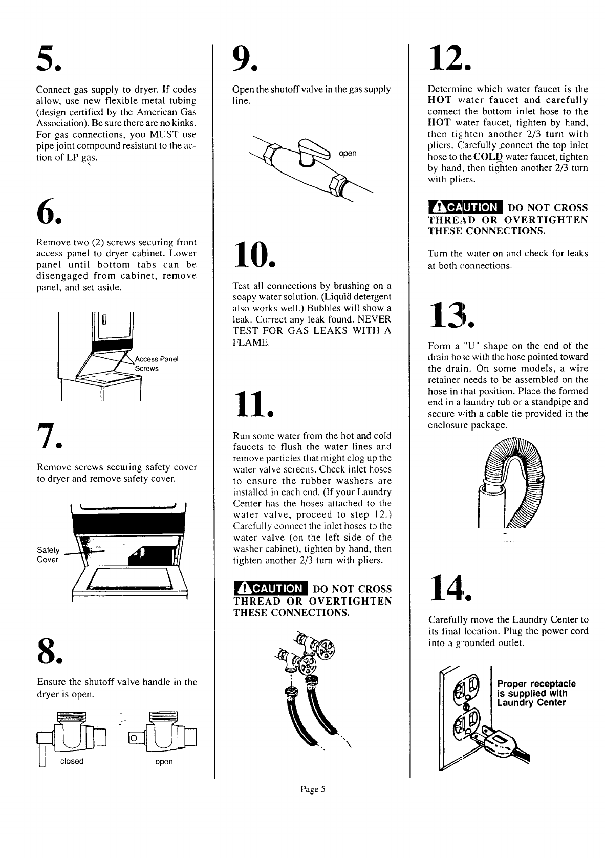
Connect gas supply to dryer. If codes
allow, use new flexible metal tubing
(design certified by the American Gas
Association). Be sure there are no kinks.
For gas connections, you MUST use
pipe joint compound resistant to the ac-
tion of LP gas.
0
Remove two (2) screws securing front
access panel to dryer cabinet. Lower
panel until bottom tabs can be
disengaged from cabinet, remove
panel, and set aside.
Access Panel
Screws
0
Remove screws securing safety cover
to dryer and remove safety cover.
Safety
Cover
0
Ensure the shutoff valve handle in the
dryer is open.
.2
E
open
0
Open the shutoff valve in the gas supply
line.
Test all connections by brushing on a
soapy water solution. (Liquid detergent
also works well.) Bubbles will show a
leak. Correct any leak found. NEVER
TEST FOR GAS LEAKS WITH A
FLAME.
Run :some water from the hot and cold
faucets to flush the water lines and
remove particles that might clog up the
water valve screens. Check inlet hoses
to ensure the rubber washers are
installed in each end. (If your Laundry
Center has the hoses attached to the
water valve, proceed to step 12.)
Carefully connect the inlet hoses to the
water valve (on the left side of the
washer cabinet), tighten by hand, then
tighten another 2/3 turn with pliers.
__! DO NOT CROSS
THREAD OR OVERTIGHTEN
THESE CONNECTIONS.
Determine which water faucet is the
HOT water faucet and carefully
connect the bottom inlet hose to the
HOT water faucet, tighten by hand,
then tighten another 2/3 turn with
pliers. Carefully Jzonnect the top inlet
hose to the COLD water faucet, tighten
by hand, then tighten another 2/3 turn
with pliers.
__1_! DO NOT CROSS
THREAD OR OVERTIGHTEN
THESE CONNECTIONS.
Turn the: water on and check for leaks
at both connections.
Form a"U" shape on the end of the
drain hose with the hose pointed toward
the drain. On some models, a wire
retainer needs to be assembled on the
hose in that position. Place the formed
end in a laundry tub or a standpipe and
secure with a cable tie provided in the
enclosure package.
Carefully move the Laundry Center to
its final location. Plug the power cord
into a grounded outlet.
Proper receptacle
is supplied with
Laundry Center
Page 5
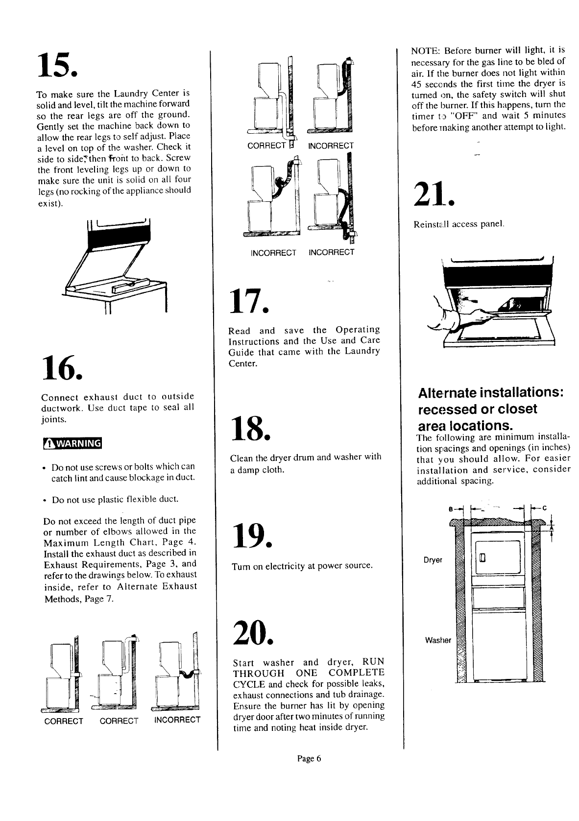
TomakesuretheLaundryCenteris
solidandlevel,tilt themachineforward
sotherearlegsareoff theground.
Gentlysetthemachinebackdownto
allowtherearlegstoselfadjust.Place
alevelontopof thewasher.Checkit
sidetoside;then_ohttoback.Screw
thefrontlevelinglegsupordownto
makesuretheunitissolidonall four
legs(norockingoftheapplianceshould
exist).
Connectexhauslduct to outside
ductwork. Use duct tape to seal all
joints.
• Do not use screws or bolts which can
catch lint and cause blockage in duct.
° Do not use plastic flexible duct.
Do not exceed the length of duct pipe
or number of elbows allowed in the
Maximum Length Chart, Page 4.
Install the exhaust duct as described in
Exhaust Requirements, Page 3, and
refer to the drawings below. To exhaust
inside, refer to Alternate Exhaust
Methods, Page 7.
i
CORRECT CORRECT INCORRECT
INCORRECT
INCORRECT INCORRECT
Read and save the Operating
Instructions and the Use and Care
Guide that came with the Laundry
Center.
Clean the dryer drum and washer with
a damp cloth.
Turn on electricity at power source.
Start washer and dryer, RUN
TItROUGH ONE COMPLETE
CYCLE and check for possible leaks,
exhaust connections and tub drainage.
Ensure the burner has lit by opening
dryer door after two minutes of running
time and noting heat inside dryer.
NOTE: Before burner will light, it is
necessary for the gas line to be bled of
air. If tile burner does not light within
45 seconds the first time the dryer is
turned on, the safety switch will shut
off the burner. If this happens, turn the
timer to "OFF" and wait 5 minutes
before making another attempt to light.
Reinstall access panel.
Alternate installations:
recessed or closet
area locations.
The following are minimum installa-
tion spacings and openings (in inches)
that you should allow. For easier
installation and service, consider
additional spacing.
Dr/or
Washer
Page 6
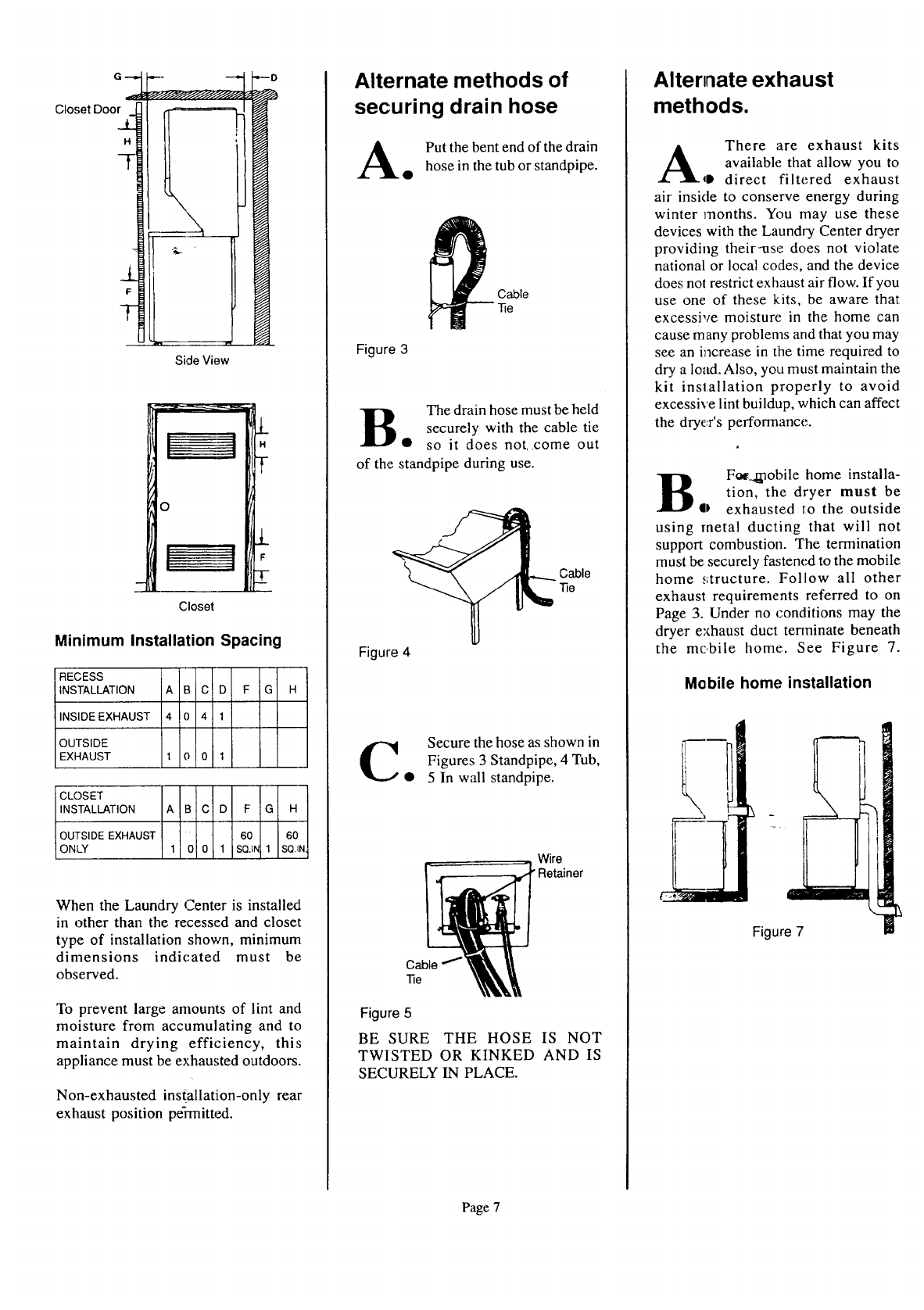
G D
Closet Doe
Side View
H
0
Closet
Minimum Installation Spacing
RECESS
INSTALLATION A B C D F G H
INSIDE EXHAUST 4 0 41
OUTSIDE
EXHAUST 1 0 0 1
CLOSET
I_N_r-ALLATION A B C D F G H
0 SIDE EXHAUST 60 60
C _Y 1 0 0 1 SQJ_ 1 SQ._N.
When the Laundry Center is installed
in other than the recessed and closet
type of installation shown, minimum
dinaensions indicated must be
observed.
To prevent large amounts of lint and
moisture from accumulating and to
maintain drying efficiency, this
appliance must be exhausted outdoors.
Non-exhausted ins(allation-only rear
exhaust position peqTnitted.
Alternate methods of
securing drain hose
A Put the bent end of the drain
• hose in the tub or standpipe.
_ able
-Re
Figure 3
B The drain hose must be held
securely with the cable tie
• so it does not. come out
of the standpipe during use.
Cable
-Re
Figure 4
C Secure the hose as shown in
Figures 3 Standpipe, 4 Tub,
• 5 In wall standpipe.
Wire
"Retainer
Cable
"Re
Figure 5
BE SURE THE HOSE IS NOT
TWISTED OR KINKED AND IS
SECURELY IN PLACE.
Alternate exhaust
methods.
There are exhaust kits
A available that allow to
you
qD direct filtered exhaust
air inside to conserve energy during
winter months. You may use these
devices with the Laundry Center dryer
providing their-use does not violate
national or local codes, and the device
does not restrict exhaust air flow. If you
use one of these kits, be aware that
excessive moisture in the home can
cause many problems and that you may
see an i_3crease in the time required to
dry a load. Also, you must maintain the
kit installation properly to avoid
excessive lint buildup, which can affect
the dryc:r's performance.
B Fac._.l_obile home installa-
tion, the dryer must be
• exhausted to the outside
using metal ducting that will not
support combustion. The termination
must: be securely fa,;tened to the mobile
home _,;tructure. Follow all other
exhaust requirements referred to on
Page 3. Under no conditions may the
dryer ez_haust duct terminate beneath
the mobile home. See Figure 7.
Mobile home installation
Figure 7
Page 7
Mran
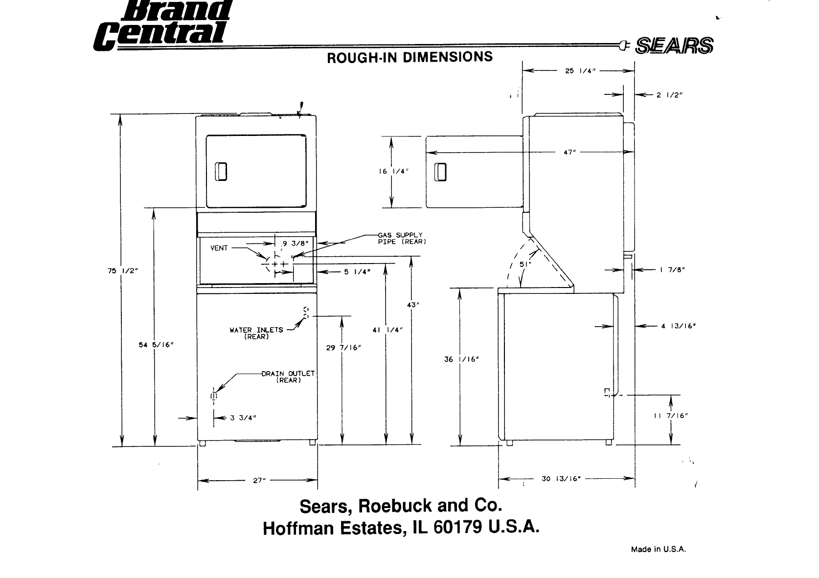
75 I12"
54 5116"
,9 3/8"
| l
WATER INLETS y'
(REAR )
LJ
/--DRAIN OUTLET
(REAR)
(!;
I
3314"
-,,
27 '_
ROUGH-IN DIMENSIONS
I i
16 I/4"
j _
25 1/4"_
!
47
AS SUPPLY
IPE (REAR)
-4C----- 5 114 n
"_ 41
J
29 7116"
l 4!"
114"
36 16"
/
/
/51"
/
P
U
30 13/16"
--,_=---2 I/2"
Z
I7/8"
-_----- 4 13/16"
II 7/16"
Sears, Roebuck and Co.
Hoffman Estates, IL 60179 U.S.A.
Made in U.S.A.
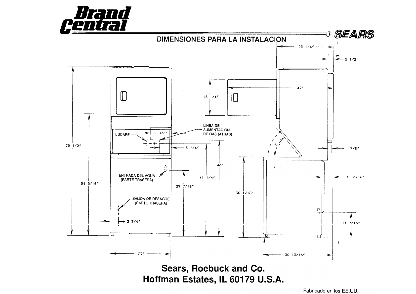
Brand
75 /2"
54 5/!6"
I
|
ENTRADA DEL AGUA _'jJ
(PARTE TRASERA)
/-SALIDA DE DESAGOE
j PARTE TRASERA)
ql
i
_"3 314"
I
L_
27"
DIMENSIONES PARA LA INSTALAClI_ _
I
LINEA DE
AUMENTACION
DE GAS (ATRAS)
S/EARS
43"
41 I/4"
29 7116"
36 1/16"
! r Ir
I
I
/
/
/51"
/
2t/2"
LJ
I 7/8"
"_-- 413116"
!! 7/!6"
1 ,
Sears, Roebuck and Co.
Hoffman Estates, IL 60179 U.S.A.
Fabricado en los EE.UU.
