KENMORE Laundry Centers Manual 98010140
User Manual: KENMORE KENMORE Laundry Centers Manual KENMORE Laundry Centers Owner's Manual, KENMORE Laundry Centers installation guides
Open the PDF directly: View PDF ![]() .
.
Page Count: 9
SAFA/ S
_y
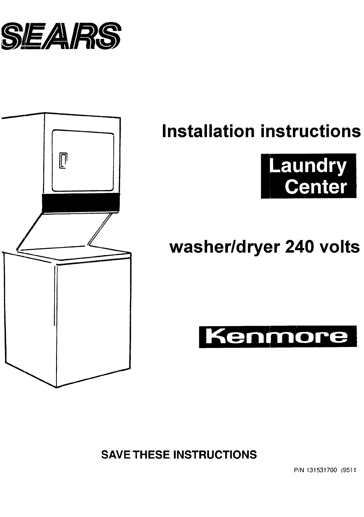
Installation instructions
// washer/dryer 240 volts
SAVE THESE INSTRUCTIONS
P/N 131531700 (9511
Before you begin.
Please read these instructions all the
way !:hrough.
screwdriver screwdriver
_ _JPliers
/_ Socket Level
You need these tools to
install Kenmore
your
ko Laundry Center. Get
them together in one place to keep track
o f them.
B_ Check the spot where :you
are going to install the
• Laundry Center. Proper
installation is your responsibility. Make
sure you have everything necessary for
proper installation.
[_'[q_l] You will need to meet
State code/law requirements: So:me
Codes keep from or limit installation of
clothes dryers in residential garages,
closets, mobile homes and sleeping
quarters. (Check with your local
building inspector.)
Important: Observe all governing
codes and ordinances.
Location
Size: Must be large enough to fully open
dryer door. For :recessed or closet
installations see Page 5 for spacing; for
product dimensions see the last page of
these instructions.
Support: The floor must be able to
support the appliance loaded weight of
500 pounds.
Level Floor: Maximum floor slcpe
under Laundry Center is 1 inch.
Protection from the weather:
Proper operation of dryer cyci:es
requires temperatures above 45°F. As
some water remains in the washer, do
not store or operate the washer below
32°F. For storage below 32°F. see Use
and Care Guide for "Winterizing."
[]It is the personal responsibility of
the customer to ensure that gasoline,
paint, thinners and other flammable
materials are not used or stored near the
Laundry Center. Fumes from these
materials could result in fire, explosion
or personal injury.
[_ Never inst_rll th_ Laundry Center
up against draperies or curtains and be
sure to keep any and all items from
falling or collecting behind the Laundry
Center.
_!_ Replace all access or service panels
before operating Laundry Center.
Recommended
grounding instructions
Electrical ground is required
on this appliance,
This appliance must be grounded. In the
event of malfunction or breakdown,
grounding will reduce the risk of
electric shock by providing a path of
least resistance for electric current.
Improper connection of
the equipment-grounding conductor
can result in a risk of electric shock.
Check with a qualified electrician or
serviceman if you are in doubt as to
whether the appliance is properly
grounded.
Electrical requirements
1. A.3-wire single phase 120/240 volt
60Hz AC only electrical supply (or
3-wire 120/208 volt if specified on
nameplate) is required on a separate
30 ampere circuit, fused on both
sides of the line (time-delay fuse or
circuit breaker is recommended). Do
not have a fuse in the neutral or
ground circuit.
2, If a power supply cord is used, it:
must be a 30 amp rated flexible type
with three open end spade lug
connectors with upturned ends or
closed loop terminal connectors. A
U.L. recognized strain relief (U.L.
mark on it or Sears Part No. 687000)
to fit a one inch hole must be used.
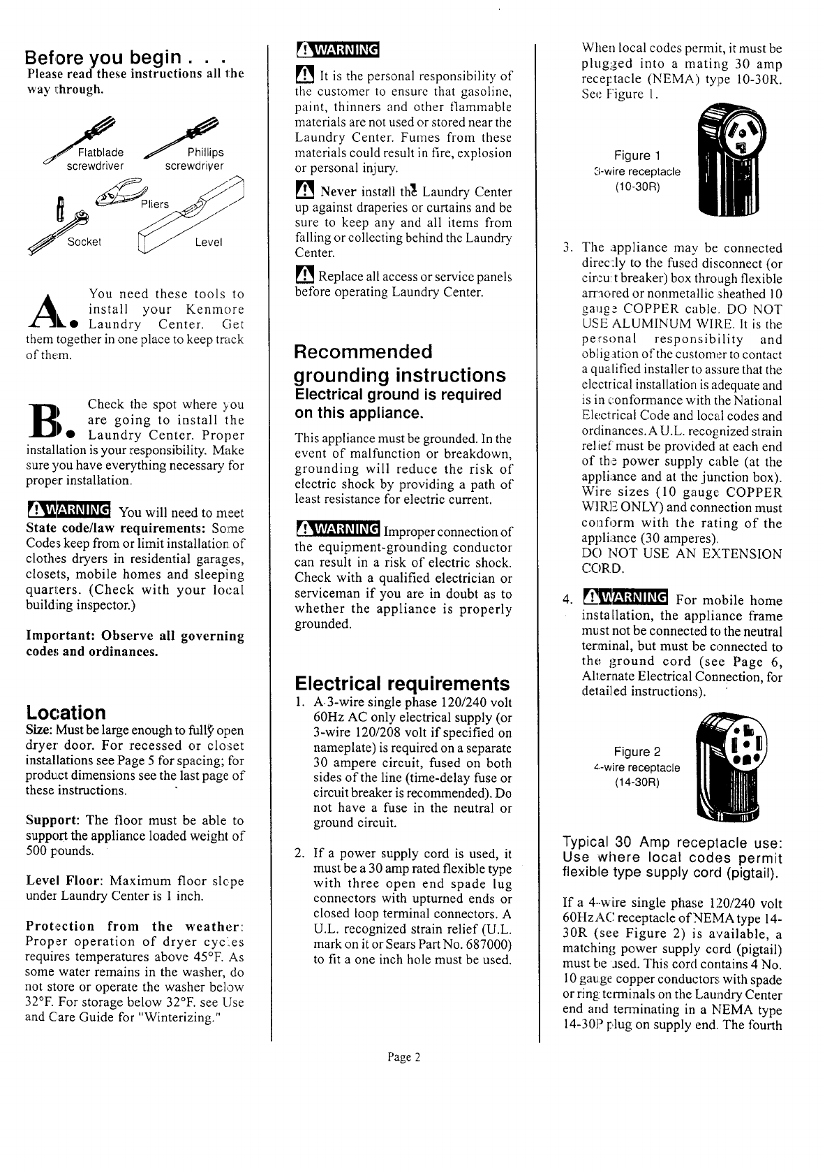
When local codes permit, it must be
plug_,_ed into a mating 30 amp
rece[.tacle (NEMA) type 10-30R.
See l-'igure 1.
Figure 1
3-wire receptacle
(10-30R)
,The ;appliance may be connected
direc:ly to the fused disconnect (or
circu! t breaker) box thro ugh flexible
arraored or nonmetallic _heathed 10
gaug_ COPPER cable. DO NOT
USE ALUMINUM WIRE. It is the
personal responsibility and
obligation of the customer to contact
a qualified installer to assure that the
electrical installation is adequate and
is in conformance with the National
Electrical Code and local codes and
ordinances.A U.L. recognized strain
relief must be provided at each end
of the power supply cable (at the
appliance and at the junction box).
Wire sizes (10 gauge COPPER
WI RE ONLY) and connection must
conform with the rating of the
appliance (30 amperes),
DO NOT USE AN EXTENSION
CC)RD.
._h-__ For mobile home
installation, the appliance flame
must not be connected to the neutral
tez:rninal, but must be connected to
the ground cord (see Page 6,
Alternate Electrical Connection, for
detailed instructions).
Figure 2
z.-wire receptacle
(14-30R)
Typical 30 Amp receptacle use:
Use where local c:odes permit
flexible type supply cord (pigtail).
If a 4--wire single phase 1:20/240 volt
60HzA(: receptacle of NEMA type 14-
30R (see Figure 2) is available, a
matching power supply cord (pigtail)
must be ased. This cord contains 4 No.
10 gauge copper conductors with spade
or ring terminals on the Laundry Center
end and terminating in a NEMA type
14-307 [.,lug on supply end. The fourth
Page 2
(grounding) conductor must be
identified by a green cover and the
neutral conductor by a white cowzr.
Cord should be Dpe SRD or SRDT,
with a U.L. recognized strain relief, and
be at least 3 feet and no more than 6
feet leng. The 4-wire power supply cord
and strain relief are not provided with
the Laundry Center.
NOTE: Laundry Center dryers
operating on 208 volt power supply will
have longer drying times than dryers
operating on 240 volt power supply.
Exhaust requirements
Four Inch Metal Exhaust Duct is re-
quired. (Do not use 3-inch exhaust
duct.) Metal flexible duct may be used.
DO NOT USE PLASTIC FLEXIBLE
DUCT.
___"d] For Safety:
_?_ Do not exhaust dryer into a
chimney, furnace cold air duct, attic or
crawl space, or any other duct used for
venting. Accumulated lint could
become a fire hazard or moisture could
cause damage.
[]The exhaust system should be
cleaned periodically, at least every 18
months.
Flexible duct should never be
instaEed concealed in walls, ceiling or
floor.
Use Duct Tape to seal all joints.
Exhausting the dryer outside is
recormnended.
For Mobile Home" Exhaust
Requirements see Page 6, Alternate
Exhaust Methods, for detailed
instructions.
The Fxhaust Duct should end with
an Exhaust Hood to prevent exhaus:ed
air returning into dryer. The outlet of
the hood must be at least 12 inches from
the ground or anything else that may
be in the path of the exhaust.
A 2-1/2 inch outlet-Exhaust Hood
should be used with short systems only.
This outlet creates greater backward
pressure than other hood types.
Exhaust Hoods with screen or
magnetic latches should not be used.
The Maximum Length of the exhaust
system depends upon the type of duct
used, number of elbows and type of
exhaust hood. The maximum length for
both rigid and flexible duct is shown in
chart.
EXHAUST DUCT LENGTHS (FEET):
EXHAUST HOOD TYPE
Number of
190°Turns _ _:_] _,,
I I
4" LOUVERED 2 112"
PfAXIP'IUPI LENGTH OF 4-INCH DIAMETER
RIGID METAL DUCT
056' 56' 42'
1 46' 46' 36'
2 34' 34' 28'
3 32' 32' 18'
PIAXIPIUH LENGTH OF 4-INCH DIAMETER
FLEXIBLE METAL DUCT
0 30' 30' 22'
1 22' 22' 14'
2 16' 16' 10
3 10' 10' 5'
Exhaust Systems longer than specified
will:
•Shorten the life of the dryer.
• Reduce the performance, such as
cause longer drying times and
increases the use of energy.
•Accumulate lint.
The Laundry Center may be exhausted
four (4) ways with rear flush
installation:
1. Straight back.
2. Down (8" length of 4" rigid duct
andl elbow down).
3. Left (8" length of 4" rigid duct, 1
elbow down and 1 elbow left).
4. Right (8" length of 4" rigid duct, 1
elbow down and 1 elbow right).
To exhaust 'up, add an 11" length of
standard 4" diameter duct and a 90 °
elbow. The unit will be positioned about
4-1/2" away from the wall (flush to wall
exhausting may be done by going below
the dryer then sideways.)
Water supply ,and drain
requi rements
Hot and Cold water faucets within 4
feet of back of the Laundry Center and
enough pressure-(5-100 PSI) are
required ....
Water Heater should be set to deliver
130°F. oi above water to the washer for
best results.
To drain the Laundry Center washer,
you need either a 20-gallon laundry tub
or 1-I14 inch diameter standpipe having
a minimum carry-away capacity of 16
gallon:_ t:er minute. The minimum tub
or standpipe height is 33 inches from
the bottom of the washer. The maximum
tub or slandpipe height is 96 inches
from lhc bottom of the washer. For
installations requiting a longer drain
hose, have a qualified technician install
a longer hose according; to your model
number. For drain systems in the floor,
install a siphon break kit, PIN
537767S100. Both components are
available from Sears Parts Department.
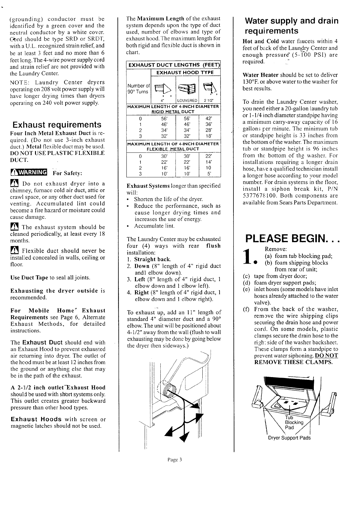
PLEASE BEGIN...
0
(c)
(d)
(e)
(O
Remove:
(a) foam tub blocking pad;
(b) foam shipping blocks
from rear of unit;
tape from dryer door;
foam dryer support pads;
inlet hoses (some models have inlet
hose s already attached to the water
valve).
From the back of the washer,
remove the wire shipping clips
securing the drain hose and power
cord. On some mode, Is, plastic
clamps secure the drain hose to the
righ: side of the washer backsheet.
These clamps form a standpipe to
prevent water siphoning. DO NOT
REMOVE THESE CLAMPS.
Dryer Support Pads
Pagc 3

Using the four shipping carton
corner posts (two on each
• tit side), carefully lay the
Laundry Center on its left side aad
remove the foam shipping base.
Shippin_
Plastic Spacer Block Shipping
Blocks Clips
Mechanis (_
Sh"ippingBolt[h_'_'__ n, I1_
Pad -- Hose
Shipping Carton
Corner Posts
Using the ratchet with 3/8 inch
socket, remove mechanism
• shipping bolt. Remove plastic
spacer block fromcenter of base using
adjustable pliers.
NOTE: If the Laundry Center is to be
transported at a later date, the tub
blocking pad, shipping bolt and plastic
spacer block should be retained.
__ Tub
Blocking
Pad
Plastic
Spacer _ Shipping
0Return Laundry Center to
upright position.
Install 3-wire power supply
,cord.
• a. Remove the terminal block
cover located at the rear of the dryer.
b. Jinstall U.L. approved strain relief
(Figure 11) in oneinch hole on dryer
back below terminal block opening.
c. Thread U.L. a]_proved 30 amp
power cord through strain relief.
d. Connect the center wire of the power
cord to the center silver colored
terminal screw of the terminal block
and tighten securely.
e. Connect the other wires to the outer
terminals and tighten securely
(Figure 12).
f. Replace the terminal block cover.
Run some water from the hot
and cold faucets to flush the
• water lines and remove
particles that might clog up the water
valve screens. Check inlet hoses to
ensure the rubber washers are installed
in each end. (If your laundry center has
the hoses attached to the water valve,
proceed to step 7.) Carefully connect
the inlet hoses to the water valve (on
the left side of the washer cabinet),
tighten by hand, then tighten another
2/3 turn with pliers.
_DO NOT CROSS
THREAD OR OVERTIGHTEN
THESE CONNECTIONS.
Determine which water faucet
is the HOT water faucet and
• carefully connect the bottom
inlet hose to the HOT water faucet,
tighten by hand, then tighten another
2/3 turn with pliers. Carefully connect
the top inlet hose to the COLD water
faucet, tighten by hand, then tighten
another 2/3 turn with pliers.
__! DO NOT CROSS
THREAD OR OVERTIGHTEN
THESE CONNECTIONS.
Turn the water on and check for leaks
at both connections.
_.,x.
Form a "U" shape on the end
of the drain hose with the hose
• pointed toward the drain. On
some models, a wire retainer needs to
be assembled on the hose in that
position. Place the formed end in a
laundry tub or a standpipe and secure
with a cable tie provided in the
enclosure package.
0
Carefully move
the laundry center
to its final
location. Plug the
power cord into a
grounded outlet.
Page 4
l0 To make sure the Laundry
Center is solid and level, tilt
• the machine fo_vard so the
rear legs are offthe ground. Gently set
the machine back down to allow the
rear legs to self adjust. Place a level on
top of the washer. Check it side to side,
then fi'oat to b_ick. Screw the front
leveling legs up or down to make sure
the urit is solid on all four legs (no
rocking of the appliance should exist).
l l Remove two (2) screws
securing front access panel
• to dryer cabinet. Lower
pane] antil bottom tabs can be
disengaged from cabinet, remove
panel, and set aside.
Acess
Panel
Screws
Connect exhaust duct to
12 outside ductwork. Use duct
• tape to seal all joints. Do not
exceed the length of duct pipe or
number of elbows allowed in the
Maximum Length Chart, Page 3. Install
the exhaust duct as described in
Exhaust Requirements, Page 3, and
refer to the drawings below. To exhaust
inside, refer to Alternate Exhaust
Methods, Page 6.
CORRECT"
INCORRECT INCORRECT
£4z•
CORRECT INCORR ECT
CORRECT --INCORRECT
123 Read and save the Operat-
ing Instructions and the Use
• and Care Guide that
came: with the Laundry Center.
!l Clean the dryer drum and
washer tub with a damp
IO cloth.
l_ Turn on electricity at power
• source.
Start washer and dryer.
1(_ RUN THROUGH ONE
• COMPLETE CYCLE ;and
check for possible leaks, exhaust con-
nections and tub drainage.
1_70 Reinstall access panel.
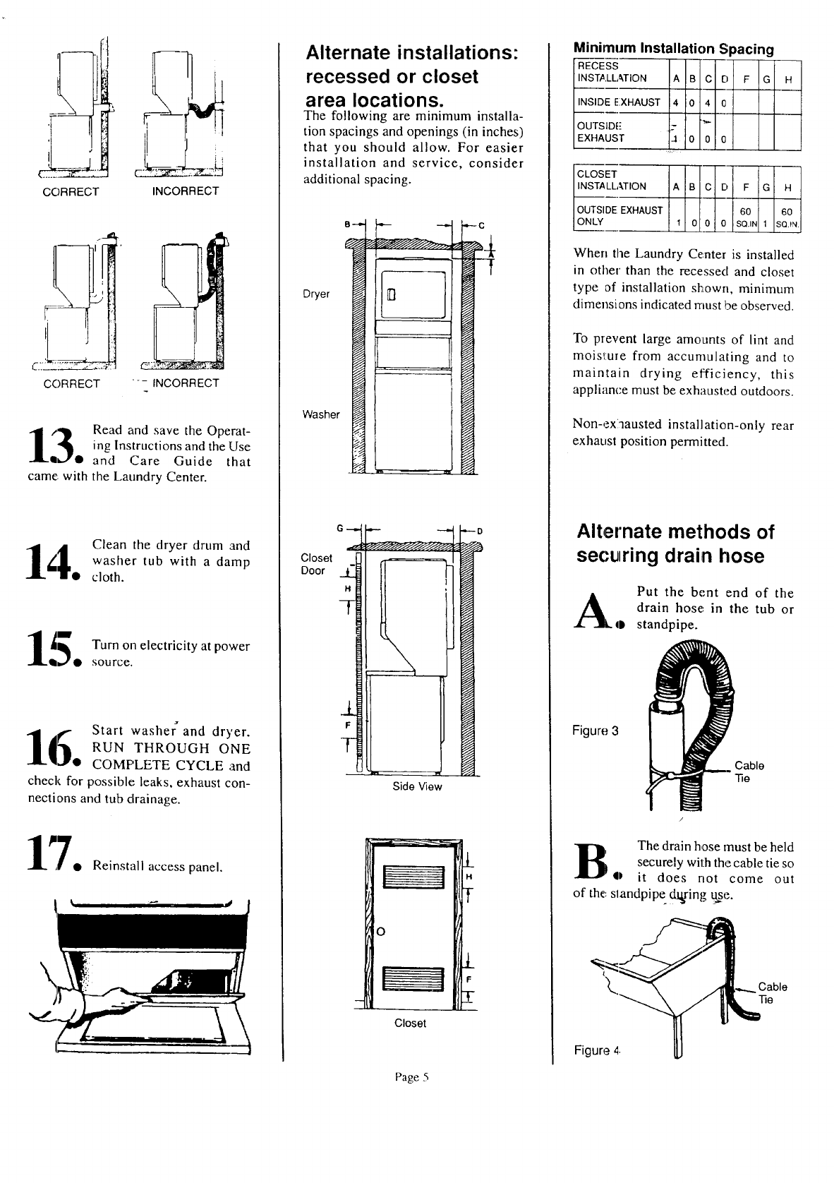
Alternate installations"
recessed or closet
area locations.
The following are minimum installa-
tion spacings and openings (in inches)
that you should allow. For easier
installation and service, consider
additional spacing.
B
Dryer
Washer
_3
_C
f
GD
Closet
Door
Side View
H
o
Closet
Minimum Installation Spacing
RECESS
INSTALLATION A B C l El F G H
INSIDE XHAUST 4 0 40
OUTSID[-"
EXHAUST -1 00 0
CLOSET D F
._.LLATION A B C G H
tlOUTSI EXHAUST 0 60N 60
IONLY 1 O' 0 1 SQ._N.
When the Laundry Center is installed
in other than the recessed and closet
type of installation shown, minimum
dimensions indicated must be observed.
To prevent large amounts of lint and
mois_:ure from accumulating and to
maintain drying efficiency, this
appliance must be exhausted outdoors.
Non-exlnausted installation-only rear
exhaust position permitted.
Alternate methods of
se(-uring drain hose
A ql)
Figure 3
Put the bent end of the
drain hose: in the tub or
standpipe.
Cable
Tie
B The drain hose must be held
securely with the cable tie so
• it does not come out
of the, slandpipe dslsring_e.
Figure 4.
Page 5
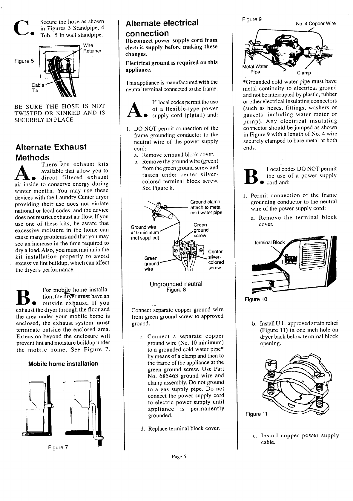
Figure 5
Secure: the hose as shown
in Figures 3 Standpipe, 4
Tub, 5 In wall standpipe.
Wire
• Retainer
Cable 1
-nd
BE SURE THE HOSE IS NOT
TWISTED OR KINKED AND IS
SECURELY IN PLACE.
Alternate Exhaust
Methods
There-_are exhaust kits
A
/_, available that allow you to
Z--__L• direct filtered exhaust
air inside to conserve energy during
winter months. You may use these
devices with the Laundry Center dryer
providing their use does not violate
national or local codes, and the device
does not restrict exhaust air flow. If you
use one of these kits, be aware that
excessive moisture in the home can
cause many problems and that you may
see an increase in the time required to
dry a load.Also, you must maintain the
kit installation properly to avoid
excessive lint buildup, which can affect
the dryer's performance.
t_ For mobile home installa-
tion, the d_r must have an
• outside exhaust. If you
exhaust the dryer through the floor and
the area under your mobile home is
enclosed, the exhaust system must
tenninate outside the enclosed area.
Extension beyond the enclosure will
prevent lint and moisture buildup under
the mobile home. See Figure 7.
Mobile home installation
Figure 7
Alternate electrical
connection
Disconnect power supply cord from
electric supply before making these
changes.
Electrical ground is required on this
appliance.
This appliance is manufactured with the
neutral terminal connected to the frame.
AIf local codes permit the use
of a flexible-type power
• supply cord (pigtail) and:
DO NOT permit connection of the
frame grounding conductor to the
neutral wire of the power supply
cord:
a. Remove terminal block cover.
b. Remove the ground wire (green)
from the green ground screw and
fasten under center silver-
colored terminal block screw.
See Figure 8.
Ground clamp
attach to metal
cold water pipe
Ground wire Green
#10 minimu round
(not supplied) screw
Center
Green silver-
ground colored
wire screw
Ungrounded neutral
Figure 8
Connect separate copper ground wire
from green ground screw to approved
ground.
C. Connect a separate copper
ground wire (No. 10 minimum)
to a grounded cold water pipe*
by means of a clamp and then to
the frame of the appliance at the
green ground screw. Use Part
No. 685463 ground wire and
clamp assembly. Do not ground
to a gas supply pipe. Do not
connect the power supply cord
to electric power supply until
appliance is permanently
grounded.
d. Replace terminal block cover.
Page 6
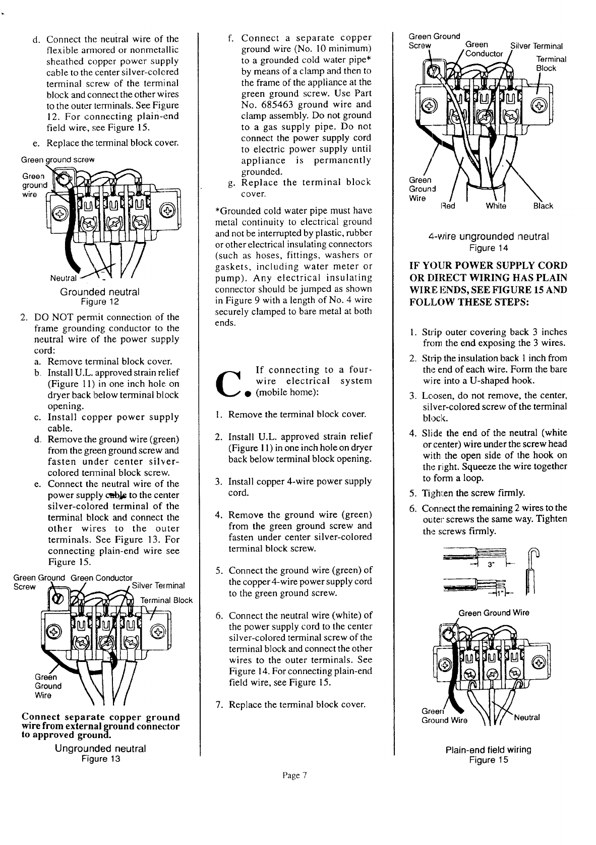
Figure 9 No. 4 Copper Wire
Metal Water
Pipe Clamp
*'Groun:ted cold water' pipe must have
metal continuity to electrical ground
and not be interrupted by plastic, rubber
or other electrical insulating connectors
(such as hoses, fittings, washers or
gaskeL';, including water meter or
pump). Any electrical insulating
connector should be jumped as shown
in Figure 9 with a length of No. 4 wire
securely clamped to bare metal at both
ends.
BLocal codes DO NOT permit
the use of a power supply
ocord and:
Per_]it connection of the frame
grounding conductor to the neutral
wire of the power supply cord:
a. Remove the terminal block
cover.
"li_rrninal Block
Figure 10
b, Install U.L. approved strain relief
(Figure 11) in one inch hole on
dryer back below terminal block
opening.
Figure 11
c. Install copper power supply
,zable.
d. Connect the neutral wire of the
flexible amaored or nonmetallic
sheathed copper power supply
cable to the center silver-colcred
terminal screw of the terminal
block and connect the other wires
to the outer terminals. See Figure
12. For connecting plain-end
field wire, see Figure 15.
e. Replace the terminal block cover.
Green ground screw
x
Green
ground
wire
Neutral
Grounded neutral
Figure 12
2. DO NOT pemait connection of the
frame grounding conductor to the
neutral wire of the power supply
cord:
a. Remove terminal block cover.
b Install U.L. approved strain relief
(Figure 11) in one inch hole on
dryer back below terminal block
opening.
c. Install copper power supply
cable.
d Remove the ground wire (green)
from the green ground screw and
fasten under center silver-
colored tenninal block screw.
e. Connect the neutral wire of the
power supply c_]_ to the center
silver-colored terminal of the
terminal block and connect the
other wires to the outer
terminals. See Figure 13. For
connecting plain-end wire see
Figure 15.
Green Ground Green Conductor
Screw Silver Telminal
Terminal Block
Ground
_qre
Connect separate copper ground
wire from external ground connector
to approved ground.
Ungrounded neutral
Figure 13
f. Connect a separate copper
ground wire (No. 10 minimum)
to a grounded cold water pipe*
by means of a clamp and then to
the frame of the appliance at the
green ground screw. Use Part
No. 685463 ground wire and
clamp assembly. Do not ground
to a gas supply pipe. Do not
connect the power supply cord
to electric power supply until
appliance is permanently
grounded.
g. Replace the terminal block
cover,
*Grounded cold water pipe must have
metal continuity to electrical ground
and not be interrupted by plastic, rubber
or other electrical insulating connectors
(such as hoses, fittings, washers or
gaskets, including water meter or
pump). Any electrical insulating
connector should be jumped as shown
in Figure 9 with a length of No. 4 wire
securely clamped to bare metal at both
ends.
If connecting to a four-
C wire electrical system
•(mobile home):
1. Remove the terminal block cover.
2. Install U.L. approved strain relief
(Figure 11) in one inch hole on dryer
back below terminal block opening.
3. Install copper 4-wire power supply
cord.
.Remove the ground wire (green)
from the green ground screw and
fasten under center silver-colored
terminal block screw.
5. Connect the ground wire (green) of
the copper 4-wire power supply cord
to the green ground screw.
.Connect the neutral wire (white) of
the power supply cord to the center
silver-colored terminal screw of the
terminal block and connect the other
wires to the outer terminals. See
Figure 14. For connecting plain-end
field wire, see Figure 15.
7. Replace the terminal block cover.
Page 7
Green Ground
Screw Green Silver Terminal
Terminal
Block
Green
Groun:l
Wire Iqed White Black
z_-wire ungrounded neutral
Figure 14
IF YOUR POWER SUPPLY CORD
OR r)IRECT WIRING HAS PLAIN
WIRE ENDS, SEE FIGURE 15 AND
FOLLOW THESE STEPS:
1. Strip outer covering back 3 inches
from the end exposing the 3 wires.
2. Strip the insulation back 1 inch from
the end of each wire. Form the bare
wire into a U-shaped hook.
3. Loosen, do not ten'love, the center,
silver-colored screw of the terminal
block.
4. Slide the end of the neutral (white
or center) wire under the screw head
with the open side of the hook on
the right. Squeeze the wire together
to form a loop.
5. Tigh_:en the screw firmly.
6. Connect the remaining 2 wires to the
outer screws the same way. Tighten
the screws firmly.
Green Ground Wire
Gree
Ground Wire _utral
Plain-end field wiring
Figure 15
Bi Mmlm
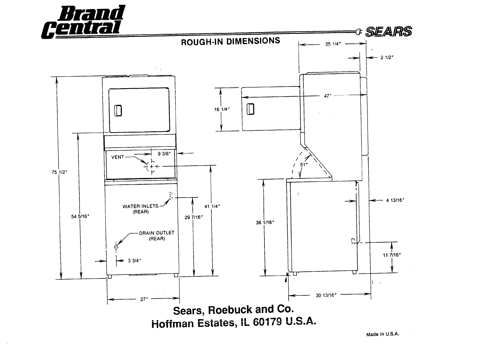
75 1/2"
i
54 5/16"
9 3/8"
VENT ----,,,,,_ I'-
w + ..)-
i ii _;
WATER INLETS _'J-_
A
(REAR)
/_-- DRAIN OUTLET
(REAR)
!
3 3/4"
J _ _ L.J
27" _-
ROUGH-IN DIMENSIONS
f
29 7116"
41 114"
I
16 114"
25 !!4"
l
36 1/16"
i/ t_ 1
30 13116"
P
LJ
b-_..
21/2"
4 13/16"
I
11 7/16"
I
_ a
Sears, Roebuck and Co.
_n4--:_ I I €2 A
Hoffman Estates, IL vv., _ v.,.,.,-,.
Made in U.S.A.
Braad
IriDim am_u.-a W
mm_BimlOi
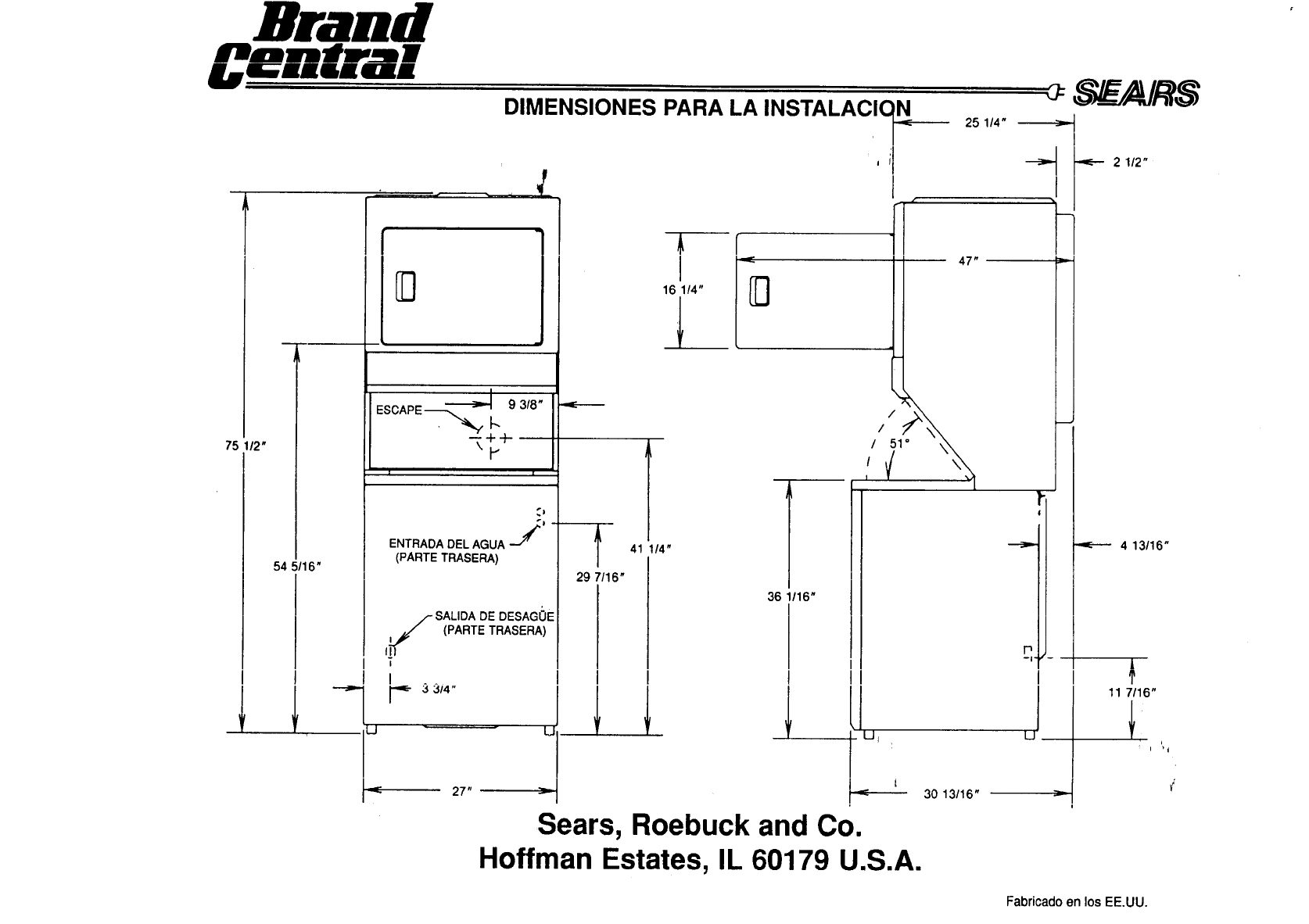
DIMENSIONES PARA LA INSTALACIC
t
75 112"
!
54 5/16"
!
93/8"
ESCAPE _ k
--++-
ENTRADA DEL AGUA :"j_
(PARTE TRASERA)
SALIDA DE DESAGOE
f_ (PARTE TRASERA)
!3 3/4"
/
U
27" _-
f
29 7/16"
41 1/4"
!
I
16 1/4"
7
36 1/16"
I
,I
LJj
Sears, Roebuck and Co.
N25 114"
47"
//51
I
30 13/16"
i
I
i
i
i
i
r
Hoffman Estates, IL 60179 U.S.A.
21/2"
4 13/16"
|
'r
11 7/16"
Ii
Fabricado en los EE,UU.
