KENMORE Water Filter Manual L0807617
User Manual: KENMORE KENMORE Water filter Manual KENMORE Water filter Owner's Manual, KENMORE Water filter installation guides
Open the PDF directly: View PDF ![]() .
.
Page Count: 12
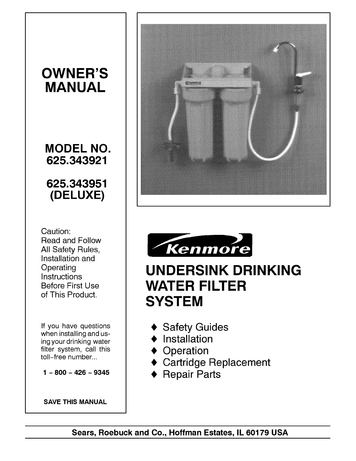
OWNER'S
MANUAL
MODEL NO.
625.343921
625.343951
(DELUXE)
Caution:
Read and Follow
All Safety Rules,
Installation and
Operating
Instructions
Before First Use
of This Product.
If you have questions
when installing and us-
ing your drinking water
filter system, call this
toll-free number...
1 -800 -426 -9345
SAVE THIS MANUAL
UNDERSINK DRINKING
WATER FILTER
SYSTEM
_, Safety Guides
• Installation
Operation
Cartridge Replacement
Repair Parts
Sears, Roebuck and Co., Hoffman Estates, IL 60179 USA
SAFETY GUIDES /SPECIFICATIONS
•Please read this entire manual before
installing and using your undersink drinking
water filter system. Be sure to follow all guides
and rules carefully. Failure to follow them
could cause personal injury or property
damage.
•Check with your local public works
department for plumbing codes. You must
follow their guides as you install the undersink
drinking water filter system.
• Use the filter system on a potable,
safe-to-drink, home COLD water supply only.
The filter cartridges will not purify water, or
make it safe to drink. DO NOT use on HOT
water (100°F, max.), microbiologically unsafe
water, or on water of unknown quality.
•Protect the drinking water filter system and
piping from freezing. Water freezing in the
system will break it.
•Your undersink drinking water filter system
will withstand up to 125 psi water pressure. If
your house water supply pressure is higher
than 100 psi, install a pressure reducing valve
before the filter system.
Maximum Supply Water Pressure
Min. - Max. Supply Water Temperature
Inlet - Outlet
125 psi
40 -100 °F
3/8" NPT, fittings and
tubing included
2
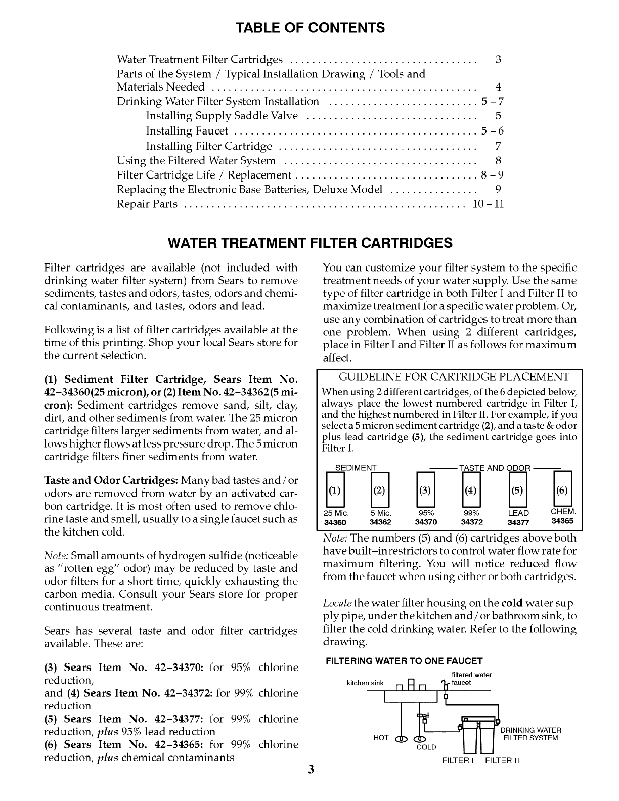
TABLE OF CONTENTS
Water Treatment Filter Cartridges .................................. 3
Parts of the System /Typical Installation Drawing /Tools and
Materials Needed ................................................ 4
Drinking Water Filter System Installation ........................... 5 - 7
Installing Supply Saddle Valve ............................... 5
Installing Faucet ............................................ 5 - 6
Installing Filter Cartridge .................................... 7
Using the Filtered Water System ................................... 8
Filter Cartridge Life /Replacement ................................. 8 - 9
Replacing the Electronic Base Batteries, Deluxe Model ................ 9
Repair Parts ................................................... 10 - 11
WATER TREATMENT FILTER CARTRIDGES
Filter cartridges are available (not included with
drinking water filter system) from Sears to remove
sediments, tastes and odors, tastes, odors and chemi-
cal contaminants, and tastes, odors and lead.
Following is a list of filter cartridges available at the
time of this printing. Shop your local Sears store for
the current selection.
(1) Sediment Filter Cartridge, Sears Item No.
42-34360(25 micron), or (2) Item No. 42-34362(5 mi-
cron): Sediment cartridges remove sand, silt, cla)_
dirt, and other sediments from water. The 25 micron
cartridge filters larger sediments from water, and al-
lows higher flows at less pressure drop. The 5 micron
cartridge filters finer sediments from water.
Taste and Odor Cartridges: Many bad tastes and /or
odors are removed from water by an activated car-
bon cartridge. It is most often used to remove chlo-
rine taste and smell, usually to a single faucet such as
the kitchen cold.
Note: Small amounts of hydrogen sulfide (noticeable
as "rotten egg" odor) may be reduced by taste and
odor filters for a short time, quickly exhausting the
carbon media. Consult your Sears store for proper
continuous treatment.
Sears has several taste and odor filter cartridges
available. These are:
(3) Sears Item No. 42-34370: for 95% chlorine
reduction,
and (4) Sears Item No. 42-34372: for 99% chlorine
reduction
(5) Sears Item No. 42-34377: for 99% chlorine
reduction, plus 95% lead reduction
(6) Sears Item No. 42-34365: for 99% chlorine
reduction, plus chemical contaminants
You can customize your filter system to the specific
treatment needs of your water supply. Use the same
type of filter cartridge in both Filter I and Filter II to
maximize treatment for a specific water problem. Or,
use any combination of cartridges to treat more than
one problem. When using 2 different cartridges,
place in Filter I and Filter II as follows for maximum
affect.
GUIDELINE FOR CARTRIDGE PLACEMENT
When using 2 different cartridges, of the 6 depicted below,
always place the lowest numbered cartridge in Filter I,
and the highest numbered in Filter II. For example, if you
select a 5 micron sediment cartridge (2), and a taste & odor
plus lead cartridge (5), the sediment cartridge goes into
Filter I.
SEDIMENT -- TASTE AND ODOR --
DD Iq Iq DD
25 Mic. 5 Mic. 95% 99% LEAD CHEM.
34360 34362 34370 34372 34377 34365
Note: The numbers (5) and (6) cartridges above both
have built-in restrictors to control water flow rate for
maximum filtering. You will notice reduced flow
from the faucet when using either or both cartridges.
3
Locate the water filter housing on the cold water sup-
ply pipe, under the kitchen and /or bathroom sink, to
filter the cold drinking water. Refer to the following
drawing.
FILTERING WATER TO ONE FAUCET
filtered water
kitchen sink El A El %faucet
l
HOT
FILTER IFILTER II
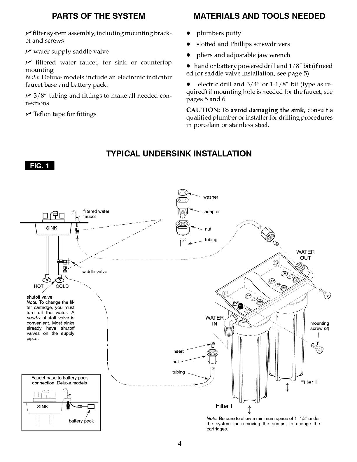
PARTS OF THE SYSTEM MATERIALS AND TOOLS NEEDED
I," filter system assembly, including mounting brack-
et and screws
1t" water supply saddle valve
I," filtered water faucet, for sink or countertop
mounting
Note: Deluxe models include an electronic indicator
faucet base and battery pack.
I," 3/8" tubing and fittings to make all needed con-
nections
1t" Teflon tape for fittings
•plumbers putty
• slotted and Phillips screwdrivers
• pliers and adjustable jaw wrench
• hand or battery powered drill and 1/8" bit (if need
ed for saddle valve installation, see page 5)
• electric drill and 3/4" or 1-1/8" bit (type as re-
quired) if mounting hole is needed for the faucet, see
pages 5 and 6
CAUTION: To avoid damaging the sink, consult a
qualified plumber or installer for drilling procedures
in porcelain or stainless steel.
TYPICAL UNDERSINK INSTALLATION
_[_i
\\,\ WATER
OUT
HOT COLD
shutoff valve
Note: To change the fil-
ter cartridge, you must
turn off the water. A
nearby shutoff valve is
convenient. Most sinks
already have shutoff
valves on the supply
pipes.
saddle valve
\\
Faucet base to battery pack
connection, Deluxe models
KIIIii i ]
r ................................... ]
s.,K /I'.--.=.-D
,!
battery pack
WATER
IN
I
mounting
screw (2)
Filter II
Filter I
Note: Be sure to allow a minimum space of 1-1/2" under
the system for removing the sumps, to change the
cartridges.
4
INSTALLATI ON STE PS
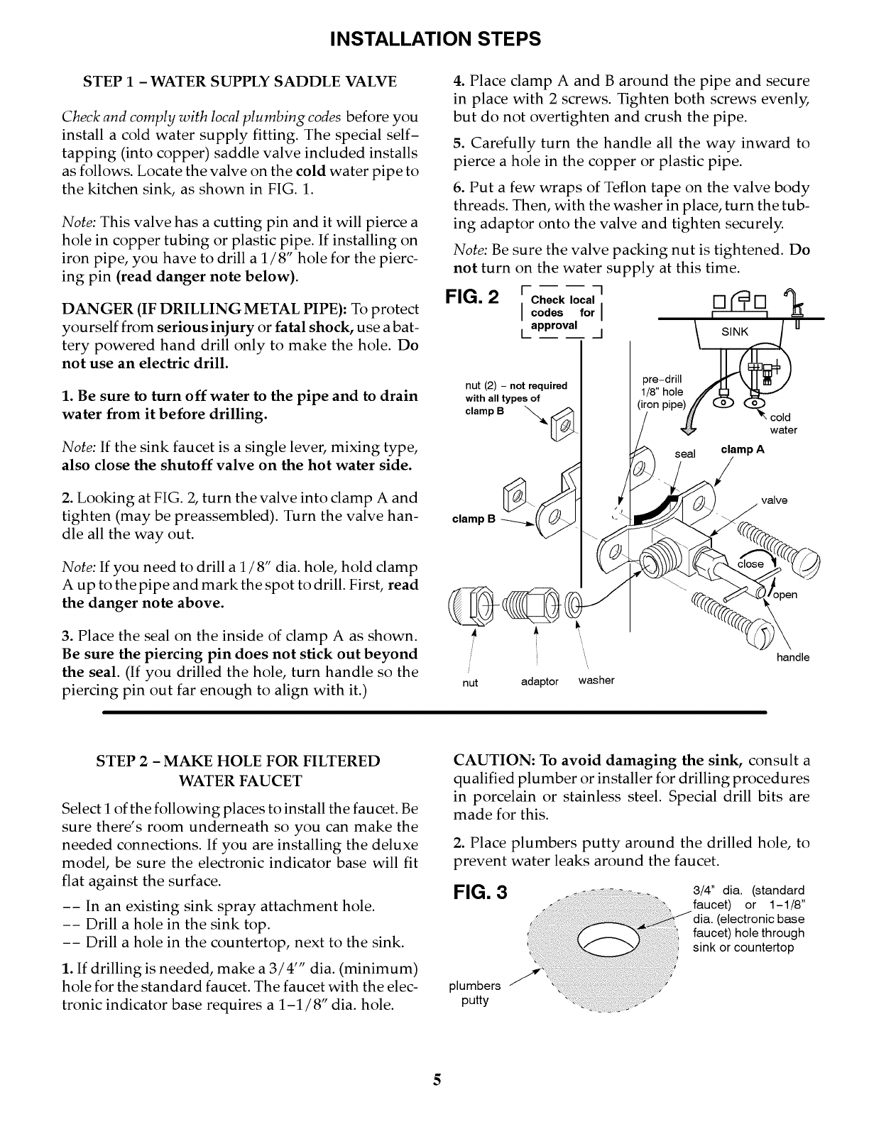
STEP 1 - WATER SUPPLY SADDLE VALVE
Check and comply with local plumbing codes before you
install a cold water supply fitting. The special self-
tapping (into copper) saddle valve included installs
as follows. Locate the valve on the cold water pipe to
the kitchen sink, as shown in FIG. 1.
Note: This valve has a cutting pin and it will pierce a
hole in copper tubing or plastic pipe. If installing on
iron pipe, you have to drill a 1/8" hole for the pierc-
ing pin (read danger note below).
DANGER (IF DRILLING METAL PIPE): To protect
yourself from serious injury or fatal shock, use abat-
tery powered hand drill only to make the hole. Do
not use an electric drill.
1. Be sure to turn off water to the pipe and to drain
water from it before drilling.
Note: If the sink faucet is a single lever, mixing type,
also close the shutoff valve on the hot water side.
2. Looking at FIG. 2, turn the valve into clamp A and
tighten (may be preassembled). Turn the valve han-
dle all the way out.
Note: If you need to drill a 1 /8" dia. hole, hold clamp
A up to the pipe and mark the spot to drill. First, read
the danger note above.
3. Place the seal on the inside of clamp A as shown.
Be sure the piercing pin does not stick out beyond
the seal. (If you drilled the hole, turn handle so the
piercing pin out far enough to align with it.)
4. Place clamp A and B around the pipe and secure
in place with 2 screws. Tighten both screws evenl_
but do not overtighten and crush the pipe.
5. Carefully turn the handle all the way inward to
pierce a hole in the copper or plastic pipe.
6. Put a few wraps of Teflon tape on the valve body
threads. Then, with the washer in place, turn the tub-
ing adaptor onto the valve and tighten securely.
Note: Be sure the valve packing nut is tightened. Do
not turn on the water supply at this time.
FIG. 2 ; CheckI°cal1codes forll [] [] £_
approval
t l
nut (2) -not required
with all types of
o,ampB
clamp B
pre-drill
1/8" hole
(iron pipe)
seal
cold
water
clamp A
valve
3pen
i
i
nut adaptor washer
handle
STEP 2- MAKE HOLE FOR FILTERED
WATER FAUCET
Select i of the following places to install the faucet. Be
sure there's room underneath so you can make the
needed connections. If you are installing the deluxe
model, be sure the electronic indicator base will fit
flat against the surface.
-- In an existing sink spray attachment hole.
-- Drill a hole in the sink top.
-- Drill a hole in the countertop, next to the sink.
1. If drilling is needed, make a 3/4'" dia. (minimum)
hole for the standard faucet. The faucet with the elec-
tronic indicator base requires a 1-1/8" dia. hole.
CAUTION: To avoid damaging the sink, consult a
qualified plumber or installer for drilling procedures
in porcelain or stainless steel. Special drill bits are
made for this.
2. Place plumbers putty around the drilled hole, to
prevent water leaks around the faucet.
FIG. 3
plumbers
putty
3/4" dia. (standard
faucet) or 1-1/8"
(electronic base
faucet) hole through
sink or countertop
5
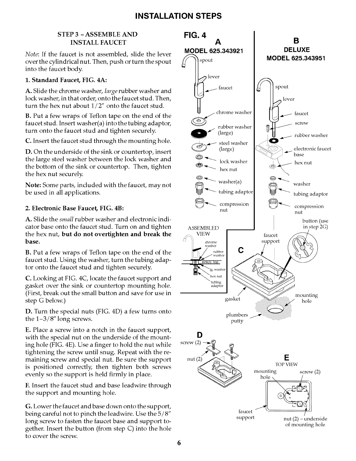
INSTALLATI ON STE PS
STEP 3 - ASSEMBLE AND
INSTALL FAUCET
Note: If the faucet is not assembled, slide the lever
over the cylindrical nut. Then, push or turn the spout
into the faucet body.
1. Standard Faucet, FIG. 4A:
A. Slide the chrome washer, large rubber washer and
lock washer, in that order, onto the faucet stud. Then,
turn the hex nut about 1/2" onto the faucet stud.
B. Put a few wraps of Teflon tape on the end of the
faucet stud. Insert washer(a) into the tubing adaptor,
turn onto the faucet stud and tighten securely.
C. Insert the faucet stud through the mounting hole.
D. On the underside of the sink or countertop, insert
the large steel washer between the lock washer and
the bottom of the sink or countertop. Then, tighten
the hex nut securely.
Note: Some parts, included with the faucet, may not
be used in all applications.
2. Electronic Base Faucet, FIG. 4B:
A. Slide the small rubber washer and electronic indi-
cator base onto the faucet stud. Turn on and tighten
the hex nut, but do not overtighten and break the
base.
B. Put a few wraps of Teflon tape on the end of the
faucet stud. Using the washer, turn the tubing adap-
tor onto the faucet stud and tighten securely.
C. Looking at FIG. 4C, locate the faucet support and
gasket over the sink or countertop mounting hole.
(First, break out the small button and save for use in
step G below.)
D. Turn the special nuts (FIG. 4D) a few turns onto
the 1-3/8" long screws.
E. Place a screw into a notch in the faucet support,
with the special nut on the underside of the mount-
ing hole (FIG. 4E). Use a finger to hold the nut while
tightening the screw until snug. Repeat with the re-
maining screw and special nut. Be sure the support
is positioned correctl_ then tighten both screws
evenly so the support is held firmly in place.
E Insert the faucet stud and base leadwire through
the support and mounting hole.
G. Lower the faucet and base down onto the support,
being careful not to pinch the leadwire. Use the 5/8"
long screw to fasten the faucet base and support to-
gether. Insert the button (from step C) into the hole
to cover the screw.
FIG. 4 A
MODEL 625.343921
_ spout
l_ lever
._ faucet
_" (large)
(_-_ steel washer
(large)
_ lock washer
_-"- hex nut
_ "-k_.. washer(a)
tubing adaptor
@'_.. compression
nut
ASSEMBLED
VIEW
chrome
washer
r
I I sink/c, top
lg. washer
hex nut
-- tubing
adaptor
C
gasket
plumbers
putty
D
screw (2) ---_ _.. x
nut (_
6
B
DELUXE
MODEL 625.343951
q spout
A lever
_ _._ faucet
_4 _ screw
L= _ rubber washer
7 ) \_
L?_-_._<:_ / electronic faucet
"_'_ _ "_ base
"_i"_ _J hex nut
_ ___._ washer
tubing adaptor
_:_ _-- compression
nut
button (use
in step 2G)
faucet
mounting
hole
E
TOP VIEW
faucet
support
mounting screw (2)
hO_eN /"_
nut (2) - underside
of mounting hole
INSTALLATION STEPS
STEP 4 - MAKE TUBING CONNECTIONS
1. Allowing some slack, measure and cut a length of
3/8" tubing to connect between the tubing adaptor,
at the supply saddle valve, and the filter system inlet,
FIG. 1. Cut the ends of the tubing square.
2. Slide a compression nut onto both ends of the tub-
ing. At the filter system end, push a tubing insert into
the tubing.
3. Connect the tubing and tighten the compression
nuts securely.
4. Repeat steps 2 and 3 to connect tubing between the
filter system outlet and the adaptor on the bottom of
the faucet stud, FIG. 1.
STEP 5 - BATTERY PACK INSTALLATION
AND CONNECTION, DELUXE MODEL ONLY
1. In a dry location, within reach of the electronic base
3 ft. leadwire, select a place for the battery pack (see
FIG. 1). The battery pack attaches to most surfaces
with a" sticky-back" Velcro strip.
2. The battery pack uses 2, size AA batteries. Check
to be sure they are installed correctly. Then, remove
the paper backing on the Velcro strip and secure in
place.
3. Fasten the electronic base leadwire connector and
battery pack connector together.
STEP 6 -FILTER CARTRIDGE INSTALLATION
Turn to page 9 and follow all steps under "Filter Cartridge Replacement".
7
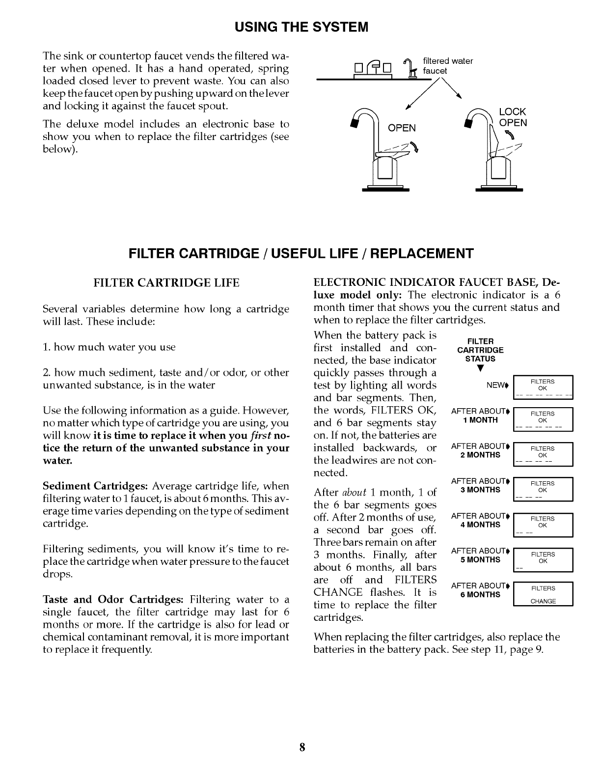
USING THE SYSTEM
The sink or countertop faucet vends the filtered wa-
ter when opened. It has a hand operated, spring
loaded closed lever to prevent waste. You can also
keep the faucet open by pushing upward on the lever
and locking it against the faucet spout.
The deluxe model includes an electronic base to
show you when to replace the filter cartridges (see
below).
filtered water
faucet
OPEN
LOCK
O E.
FILTER CARTRIDGE /USEFUL LIFE /REPLACEMENT
FILTER CARTRIDGE LIFE
Several variables determine how long a cartridge
will last. These include:
1. how much water you use
2. how much sediment, taste and/or odor, or other
unwanted substance, is in the water
Use the following information as a guide. However,
no matter which type of cartridge you are using, you
will know it is time to replace it when you first no-
tice the return of the unwanted substance in your
water.
Sediment Cartridges: Average cartridge life, when
filtering water to i faucet, is about 6 months. This av-
erage time varies depending on the type of sediment
cartridge.
Filtering sediments, you will know it's time to re-
place the cartridge when water pressure to the faucet
drops.
Taste and Odor Cartridges: Filtering water to a
single faucet, the filter cartridge may last for 6
months or more. If the cartridge is also for lead or
chemical contaminant removal, it is more important
to replace it frequently.
ELECTRONIC INDICATOR FAUCET BASE, De-
luxe model only: The electronic indicator is a 6
month timer that shows you the current status and
when to replace the filter cartridges.
When the battery pack is
first installed and con-
nected, the base indicator
quickly passes through a
test by lighting all words
and bar segments. Then,
the words, FILTERS OK,
and 6 bar segments stay
on. If not, the batteries are
installed backwards, or
the leadwires are not con-
nected.
After about 1 month, 1 of
the 6 bar segments goes
off. After 2 months of use,
a second bar goes off.
Three bars remain on after
3 months. Finall_ after
about 6 months, all bars
are off and FILTERS
CHANGE flashes. It is
time to replace the filter
cartridges.
FILTER
CARTRIDGE
STATUS
NEWl, I
FILTERS
OK
AFTER ABOUTJ FILTERS
1MONTH OK
AFTER ABOUTJ FILTERS
2MONTHS OK
AFTER ABOUTJ FILTERS
3 MONTHS OK
AFTER ABOUTJ FILTERS
4 MONTHS .... OK
AFTER ABOUTJ FILTERS
5 MONTHS __ OK
AFTER ABOUTJ FILTERS
6MONTHS CHANGE
When replacing the filter cartridges, also replace the
batteries in the battery pack. See step 11, page 9.
8
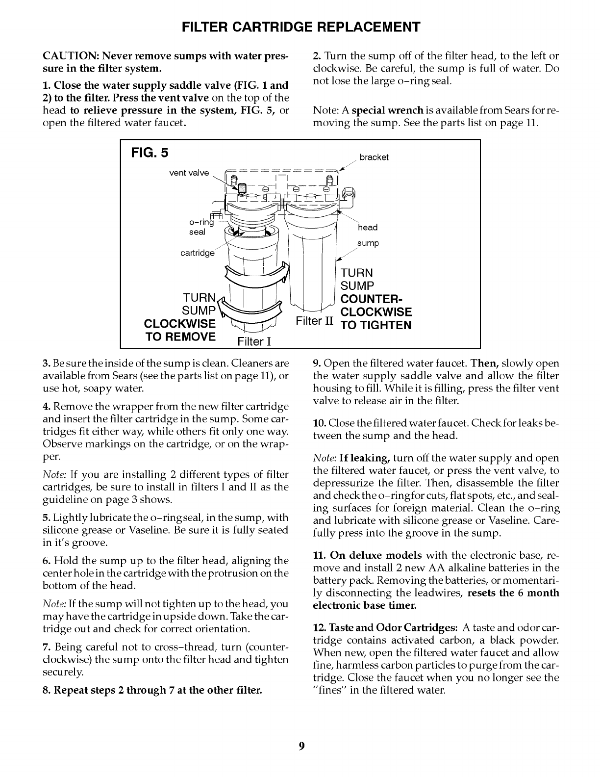
FILTER CARTRIDGE REPLACEMENT
CAUTION: Never remove sumps with water pres-
sure in the filter system.
1. Close the water supply saddle valve (FIG. I and
2) to the filter. Press the vent valve on the top of the
head to relieve pressure in the system, FIG. 5, or
open the filtered water faucet.
2. Turn the sump off of the filter head, to the left or
clockwise. Be careful, the sump is full of water. Do
not lose the large o-ring seal.
Note: A special wrench is available from Sears for re-
moving the sump. See the parts list on page 11.
FIG. 5 bracket
TO REMOVE Filter I
3. Be sure the inside of the sump is clean. Cleaners are
available from Sears (see the parts list on page 11), or
use hot, soapy water.
4. Remove the wrapper from the new filter cartridge
and insert the filter cartridge in the sump. Some car-
tridges fit either wa_ while others fit only one way.
Observe markings on the cartridge, or on the wrap-
per.
Note: If you are installing 2 different types of filter
cartridges, be sure to install in filters I and II as the
guideline on page 3 shows.
5. Lightly lubricate the o-ringseal, in the sump, with
silicone grease or Vaseline. Be sure it is fully seated
in it's groove.
6. Hold the sump up to the filter head, aligning the
center hole in the cartridge with the protrusion on the
bottom of the head.
Note: If the sump will not tighten up to the head, you
may have the cartridge in upside down. Take the car-
tridge out and check for correct orientation.
7. Being careful not to cross-thread, turn (counter-
clockwise) the sump onto the filter head and tighten
securely.
8. Repeat steps 2 through 7 at the other filter.
9. Open the filtered water faucet. Then, slowly open
the water supply saddle valve and allow the filter
housing to fill. While it is filling, press the filter vent
valve to release air in the filter.
10. Close the filtered water faucet. Check for leaks be-
tween the sump and the head.
Note: If leaking, turn off the water supply and open
the filtered water faucet, or press the vent valve, to
depressurize the filter. Then, disassemble the filter
and checkthe o-ringfor cuts, flat spots, etc., and seal-
ing surfaces for foreign material. Clean the o-ring
and lubricate with silicone grease or Vaseline. Care-
fully press into the groove in the sump.
11. On deluxe models with the electronic base, re-
move and install 2 new AA alkaline batteries in the
battery pack. Removing the batteries, or momentari-
ly disconnecting the leadwires, resets the 6 month
electronic base timer.
12. Taste and Odor Cartridges: A taste and odor car-
tridge contains activated carbon, a black powder.
When new, open the filtered water faucet and allow
fine, harmless carbon particles to purge from the car-
tridge. Close the faucet when you no longer see the
"fines" in the filtered water.
9
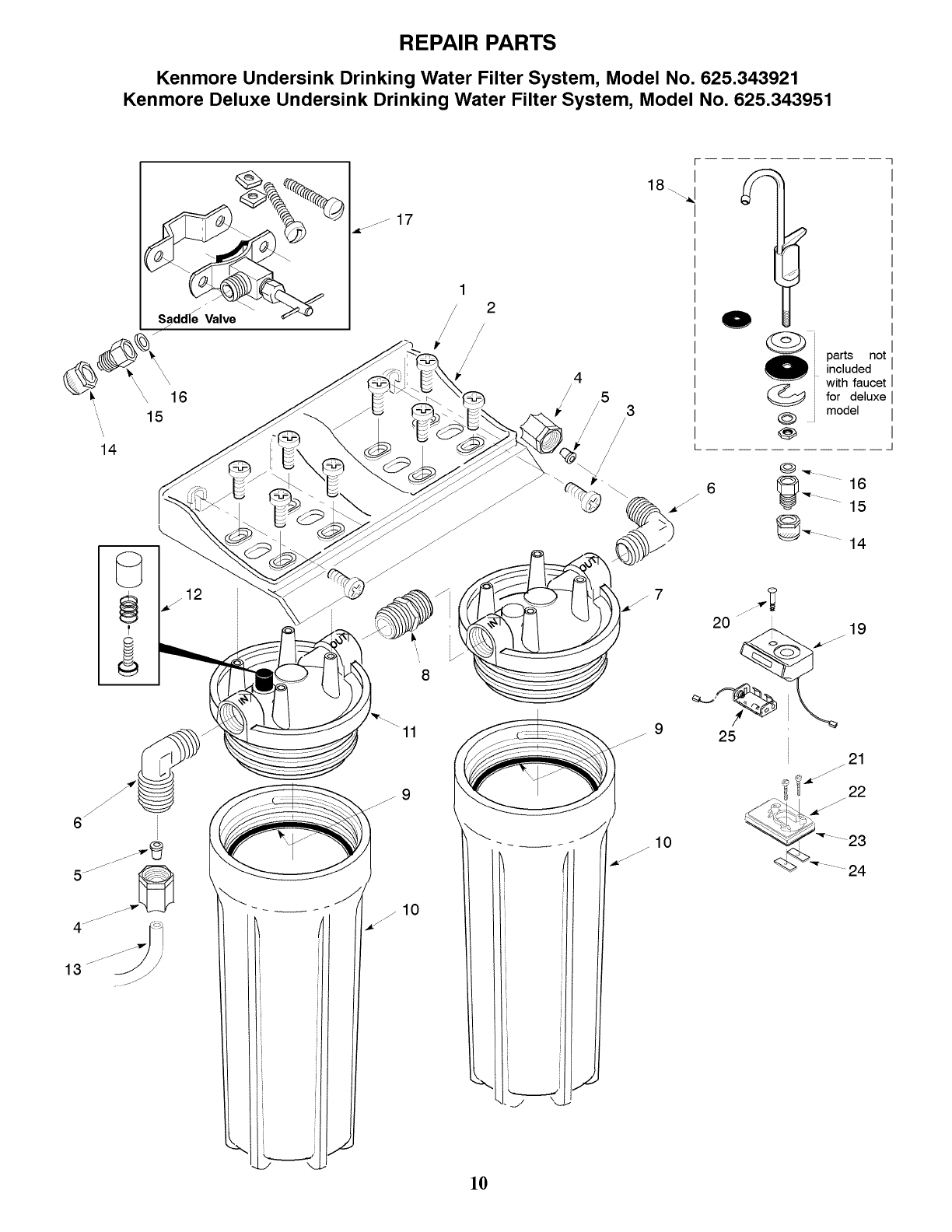
REPAIR PARTS
Kenmore Undersink Drinking Water Filter System, Model No. 625.343921
Kenmore Deluxe Undersink Drinking Water Filter System, Model No. 625.343951
\, 16
15
14
12
.... 17
//
!
/
/
18\. _k
,5 3
/
/
/L
_, ,,,,""i,,-.'¢i
/J-
//J 10
]0
6
@
parts not
included
with faucet
for deluxe
model
@_- 16
20 _¸¸ i
25
19
21
j///
_ _ 22
...... 23
_ ....... 24
REPAIR PARTS LIST
KEY PART NUMBER DESCRIPTION
NO. Model No.
625.343921
1
2
3
4
5
6
7
8
9
10
11
12
13
14
15
16
17
18
19
20
21
22
23
24
25
4,
4,
4,
4,
4,
4,
4,
4,
4,
7160453
7182502
9006053
9003203
7131349
9004503
7156535
7161255
42-34385
7156577
7160437
7164936
7174961
9043201
7207734
1260600
7011272
7207174
7207433
42-34360
42-34362
42-34370
42-34372
42-34365
42-34377
42-34330
42-34331
42-34334
Model No.
625.343951
7160453
7182502
9006053
9003203
7131349
9004503
7156535
7161255
42-34385
7156569
7160437
7164936
7174961
9043201
7207734
1260600
7011272
7207182
7189651
0900156
0900713
7163469
7090771
7115725
7162552
7207433
42-34360
42-34362
42-34370
42-34372
42-34365
42-34377
42-34330
42-34331
42-34334
Screw, #10 - 14 x 3/4" (8 req.)
Mounting Bracket (includes screws)
Screw, #10 - 14 x 1-1/4" (2 req.)
Nut, 3/8" Tube (2 req.)
Tubing Insert, 3/8" (2 req.)
Elbow, 3/8" NPT x 3/8" Tube (2 req.)
Head
Nipple, 3/8" NPT x 1 - 1/2"
O-ring, 3-3/8" I.D. x 3-5/8" O.D. (2 req.)
Sump (2 req.)
Head Assembly - includes vent assembly
Vent Assembly
Tubing, 3/8" x 90"
Nut, 3/8"
Tubing Adaptor - incls, key nos. 14 & 16 (2 req.)
Washer
Supply Saddle Valve
Faucet Assembly
Electronic Base - incls, key nos. 20 through 24
Screw, #6 - 32 x 5/8"
Screw, #6 - 32 x 1 - 3/8" (2 req.)
Faucet Support - incl. cover for screw, key no. 20
Gasket
Nut (2 req.)
Battery Pack - does not include batteries 5_
Owners Manual
Sediment Cartridge, 25 micron
Sediment Cartridge, 5 micron
Taste & Odor Cartridge, 95% chlorine reduction
Taste & Odor Cartridge, 99% chlorine reduction
Taste & Odor /Chemical Contaminate Cartridge
Taste & Odor/Lead Cartridge
Sump Cleaning Kit
Sump Cleaning Solution
Sump Removal Wrench
• not illustrated
4, available options from Sears at time
with Water Filter System
requires 2, AA alkaline batteries
of this printing, not illustrated, and not included
]!
OWNERS
MANUAL
MODEL NO.
625.343921
625.343951 Deluxe
The model number of
your drinking water filter
system is found on the
rating decal, on the
mounting bracket.
When requesting service
or ordering parts, always
provide the following in-
formation:
• Product Type
• Model Number
• Part Number
• Part Description
UNDERSINK DRINKING
WATER FILTER
SYSTEM
For the repair or replacement parts you need
Call 7 am - 7 pm, 7 days a week
1 - 800 - 366 -PART
(1 - 800 - 366 - 7278)
For in-home major brand repair service
Call 24 hours a day, 7days a week
1 - 800 - 4 - REPAIR
(1 - 800 - 473 -7247)
For the location of a
Sears Repair Service Center in your area
Call 24 hours a day, 7days a week
1 - 800 - 488 - 1222
For information on purchasing a Sears
Maintenance Agreement, or to inquire
about an existing Agreement
Call 9 am - 5 pm, Monday - Saturday
1 - 800 - 827 - 6655
Sears, Roebuck and Co., Hoffman Estates, IL 60179 U .S.A.
7207433 (1/99)
