KERI Systems KERI3000 Proximity RFID Reader User Manual NXT Reader Installation Guide
KERI Systems Inc. Proximity RFID Reader NXT Reader Installation Guide
Users Manual

NXT-1R/-3R/-5R Reader
Installation Guide
Page 1 of 2 P/N: 01997-003 Rev. A
Section 1 – Wiring and Layout Diagrams
Section 2 – Specifications and Cable Requirements
Section 3 – Reference Documentation List
Section 4 – Keri Contact Information
1.0 Wiring and Layout Diagrams
1.1 NXT-1R/-3R/-5R Readers
• This equipment has been tested and found to comply with the limits for a Class A digital device, pursuant to Part 15 of the FCC Rules.
These limits are designed to provide reasonable protection against harmful interference when the equipment is operated in a commercial
environment. This equipment generates, uses, and can radiate radio frequency energy and, if not installed and used in accordance with the
instruction manual, may cause harmful interference to radio communications. Operation of this equipment in a residential area is likely to cause
harmful interference in which case the user will be required to correct the interference at his own expense.
• Changes to this equipment not expressly approved by Keri Systems, Inc. may void FCC certification and the user’s authority to operate
this equipment.
• Operation is subject to the following two conditions: (1) this device may not cause interference, and (2) this device must accept any interference,
including interference that may cause undesired operation of the device.
2.0 Specifications
2.1 NXT-Reader Dimensions
• NXT-1R Euro Mount Prox Reader
- 3.25 inches tall by 3.25 inches wide by 0.5625 inches deep, not including wiring connectors
- 8.25 cm by 8.25 cm by 1.43 cm
• NXT-3R Mullion Reader
- 3.75 inches tall by 1.625 inches wide by 0.50 inches deep
- 9.52 cm by 4.13 cm by 1.27 cm
• NXT-5R Wall Switch Reader
- 4.50 inches tall by 3.00 inches wide by 0.625 inches deep, not including wiring connectors
- 11.43 cm by 7.62 cm by 1.59 cm
2.2 Power/Current Requirements
• 10 to 14 VDC @ 120 mA (maximum current draw at 12 VDC)
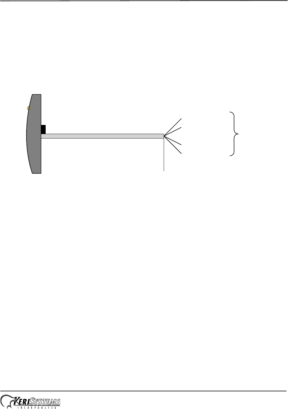
IO-Minus (White)
IO-Plus (Green)
Ground (Black)
+12 VDC (Red)
Shield (Silver)
Reader Body
Beeper
Total cable length
no greater than 1,000 feet (300 m)
RS-485
P/N: 01999-002 - Rev.B
LED
NXT-1R/-3R/-5R Installation Drawing

NXT-1R/-3R/-5R Reader
Installation Guide
Page 2 of 2 P/N: 01997-003 Rev. A
2.3 Operating Conditions
• -40°F to 150°F (-40°C to 65°C) – 0% to 90% Relative Humidity, non-condensing
2.4 Cable Requirements
RS-485 bus runs can daisy-chain together an NXT-4x4 and NXT-Reader on one line. However, the total distance for this
run can be no greater than 1,000 feet from the NXT controller.
NOTE: On long cable runs, cable resistance causes a drop in voltage at the end of the cable run. Ensure the appropriate
power and current for your device is available at the device at the end of the cable run.
3.0 Product Documentation
All Keri technical documentation can be found on the Keri CD in the Technical Documentation folder
or online at http://www.kerisys.com/pages/download/techdocs.asp.
4.0 Contact Keri Systems
- End of document. -
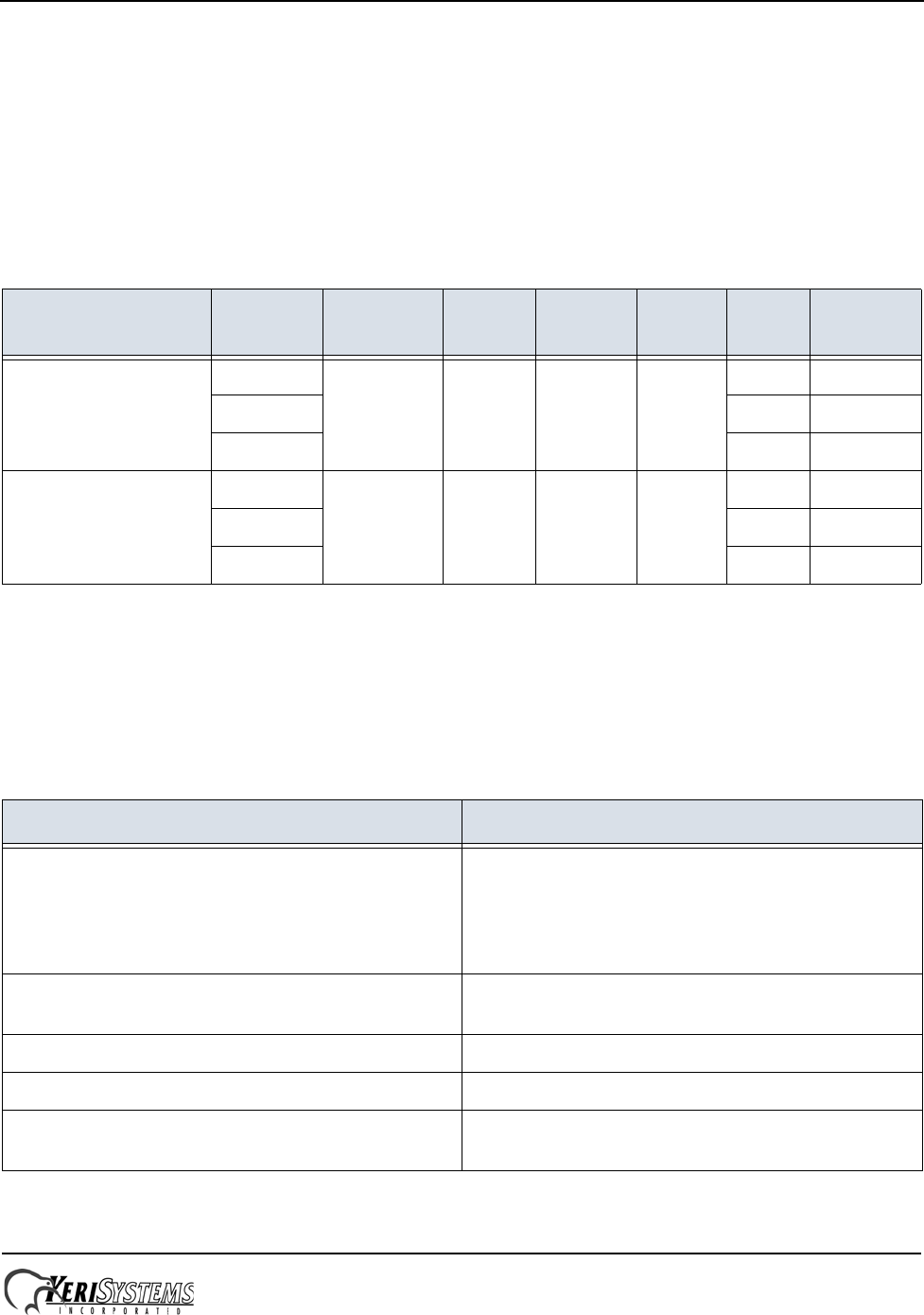
Table 1: Cable Requirements
Connection Total Run
Length # of
Conductors Shielded Stranded Twisted
-Pair AWGa
a. Heavier gauges then those listed are always acceptable.
Belden
Equivalent
RS-485 bus from
NXT-2D/-4D to NXT-
4x4 (with or without
1R/-3R/-5R Readers)
1,000 feet 4 Y Y Y 16 TBD
500 feet 18 TBD
250 feet 22 TBD
RS-485 bus from NXT-
2D/-4D to 1R/-3R/-5R
Readers only
1,000 feet 4 Y Y Y 20 TBD
500 feet 22 TBD
250 feet 26 TBD
Keri USA Keri UK, Ireland, Europe
2305 Bering Drive
San Jose, CA 95131 Unit 17
Park Farm Industrial Estate
Ermine Street
Buntingford
Herts SG9 9AZ UK
Telephone: (800) 260-5265
(408) 435-8400 Telephone: + 44 (0) 870 444 7234
Fax: (408) 435-7163 Fax:+ 44 (0) 1763 274 106
Web: www.kerisys.com Web:www.kerisystems.co.uk
E-mail: sales@kerisys.com
techsupport@kerisys.com E-mail:sales@kerisystems.co.uk
tech-support@kerisystems.co.uk