KERUI SMART TECHNOLOGY KR-G19 Kr-G19 alarm system User Manual
Shenzhen Kerui Smart Technology Co., Ltd Kr-G19 alarm system
user manual

Table of Contents
Chapter One System Introduction .............................................................................................................................. 2
Chapter Two Function Features ..................................................................................................................................... 2
Chapter Three Host Installation ..................................................................................................................................... 3
Chapter Four Operation&Setting .................................................................................................................................. 4
4.1 Initial Power-on ..................................................................................................................................................... 4
4.2 Arm ......................................................................................................................................................................... 4
4.3 Disarm .................................................................................................................................................................... 4
4.4 Stay Arm ................................................................................................................................................................ 4
4.5 Accessories Management ...................................................................................................................................... 4
4.6. Remote Control .................................................................................................................................................... 5
4.6.1 Study Remote Control ................................................................................................................................ 5
4.6.2 Delete Remote Control ............................................................................................................................... 5
4.7 Detector .................................................................................................................................................................. 6
4.7.1 Study Detectors ........................................................................................................................................... 6
4.7.2 Delete Detectors .......................................................................................................................................... 6
4.7.3 Call Alarm ON/OFF ................................................................................................................................... 6
4.7.4 Zone Attribute ............................................................................................................................................ 7
4.7.5 Network Event Code .................................................................................................................................. 7
4.7.6 NO alarm/NC alarm in Wired Zone ......................................................................................................... 7
4.8 Access Card ............................................................................................................................................................ 7
4.8.1 Study Access Card ...................................................................................................................................... 7
4.8.2 Delete Access Cards .................................................................................................................................... 8
4.9 Wireless Strobe Siren ............................................................................................................................................ 8
4.9.1 Code Match between Host & Wireless Strobe Siren ............................................................................... 8
4.9.2 Alarm Siren ................................................................................................................................................. 9
4.10 Wireless Alarm Linkage Switch ......................................................................................................................... 9
4.10.1 Code Match between Host and Smart Socket ........................................................................................ 9
4.10.2 Alarm Linkage ........................................................................................................................................ 10
Chapter Five Installation and Usage of Detectors ................................................................................................... 10
5.1 Installation and Use of Door Sensor ............................................................................................................... 10
5.2 Installation and Use of PIR Motion Detector ................................................................................................... 12
Chapter Six Troubleshooting ...................................................................................................................................... 13

Chapter One System Introduction
This alarm system with stable and reliable performance and applies 2.4-inch TFT color screen and touch keyboard with
built-in powerful CPU master and excellent operation experience. Host connects PIR motion sensors, door contacts,
smoke detectors, gas detectors and emergency button accessories etc. After receiving an alarm, host will display the
alarm zone and alarm siren on site, It’s widely used in houses, factories, schools, shops, convenience stores, financial
rooms, villas, communities and other area needed to be protected to ensure the security of the person and property at all
aspects.
Chapter Two Function Features
■ TFT color display, humanized menu, operation with voice prompt, easy to use
■ Read RFID (125KHz) card to disarm, can learn 20 cards.
■ There are 99 zones and 8 zone types optional in each zone; ON/OFF siren in each zone is available.
■ 2 wired zones, Open and Closed Alarm mode optional
■ Host can be used as a normal cellphone to call other phones directly
■ APP control host set and administration, and supports IOS/Android.
■ 8 groups scheduling Arm/Disarm function, and date can be selected to avoid arm and disarm frequently manually
to realize automatic control.
■ One-way alarm linkage wireless relay, and one-way wireless strobe siren
■ 10s automatic message recording with built-in artificial voice, so that user can know the alarm place and zone
when receive the alarm call remotely.
■ Arm/Disarm, Monitor, Speaker, siren ON/OFF, relay ON/OFF remotely.
■ Wireless study 1527 series accessories, and as much as 99 detectors and remote controls.
■ Integrate high precision clock chip so that time never lost even power failure.
■ Display the latest 99 arm/disarm, alarm and card read records with unique black box function.
■ Low-voltage indication and anti-tamper
■ Built-in rechargeable high capacity LI battery and supply power automatically when power supply failure
■ Caller ID display, power-off reminder.
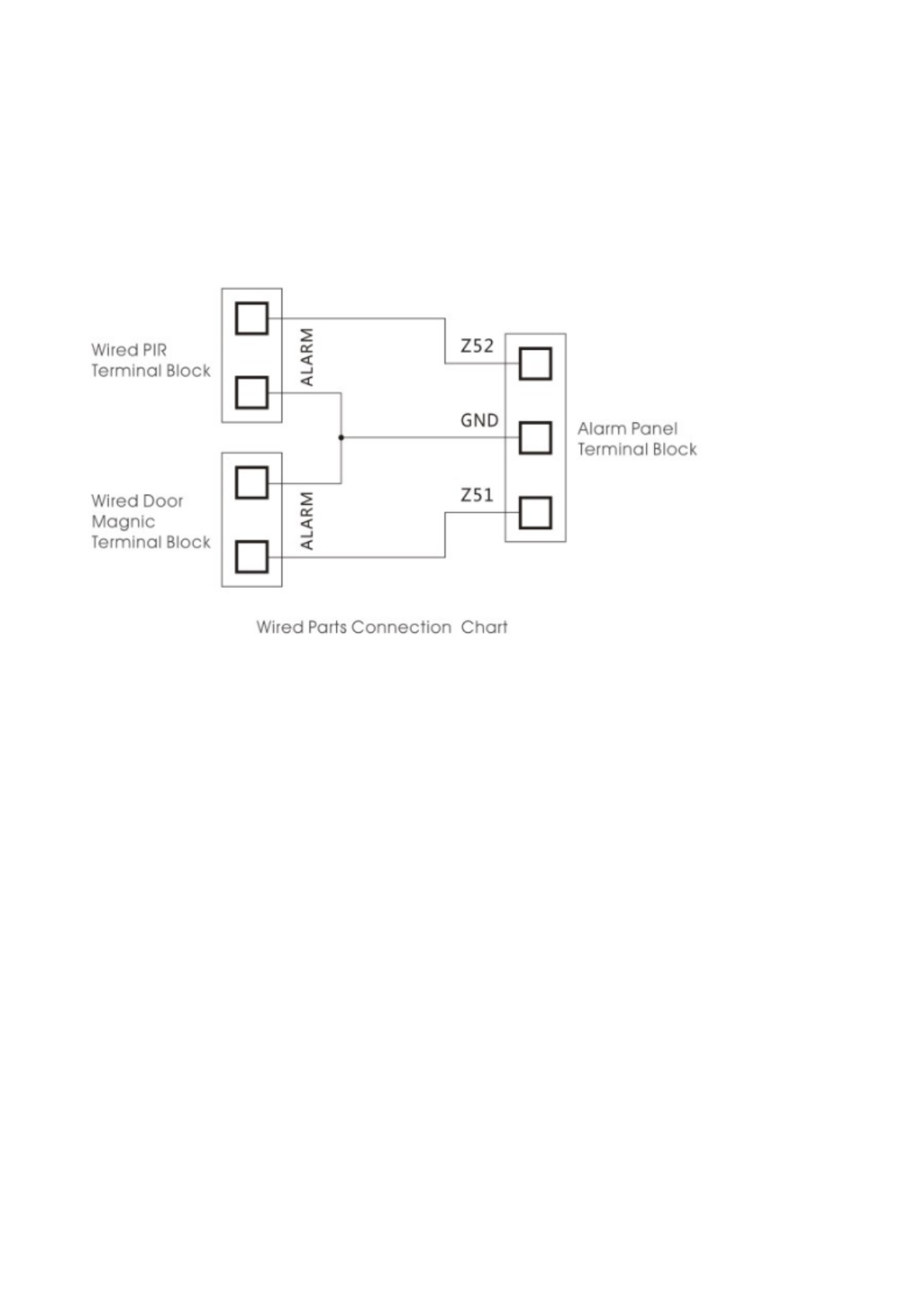
Chapter Three Host Installation
Host should be installed in the central position of the guard area to receive the signals from detectors best. Keep away
from large mental objects or appliances with high frequency interference, meanwhile, avoid the reinforced concrete walls
and fire doors barriers etc.

Chapter Four Operation&Setting
4.1 Initial Power-on
According to the installation method put the output of the powered adapter in the power supply hole of the host.
Now then, host voice prompts “ Welcome to smart voice alarm”, and switch the back-up battery to the ON state.
4.2 Arm
Arm refers to a full range of on-site alarm detection alert when nobody at home; All detectors are in working state,
when there is danger ( theft, fire, gas leak etc ) trigger the detectors, the host alarms immediately. After arming operation,
it displays and locks “arm” icon.
Remote Control operation: press key [ARM] once.
Keyboard operation: press key [ARM] once.
4.3 Disarm
Disarm refers to host panel stops the alarm or make the alarm system in a non-alert state. After disarming, when
detectors are triggered, but host doesn’t alarm (except the detectors of emergency zones and the emergency button on
remote control). After disarming operation, it displays and locks “disarm” icon.
Remote Control operation: press key [Disarm].
Keyboard operation: press key [Disarm].
4.4 Stay Arm
STAY refers to when someone at home, and for safety, the detectors in the perimeter area like doors, windows,
balconies are in working state but the detectors indoor don’t work in case of the false alarm if triggered by user himself,
then the user chooses STAY to let some detectors work and other detectors not work. STAY function needs to be set that
is the defense zones of the interior detectors should be changed to be stay zones in order to work properly. After STAY
operation, it displays and locks “STAY” icon.
Remote Control operation: press key [STAY].
Keyboard operation: press key [ARM] twice
4.5 Accessories Management
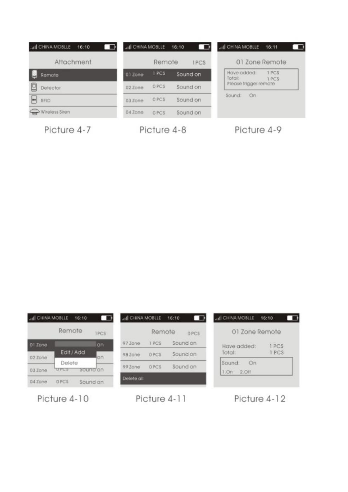
As shown in picture 4-2, press key【UP/DOWN】to move cursor to Accessories Manage icon, then press key【OK】or
input number 2 to enter accessories manage page, as shown in picture 4-7.
4.6. Remote Control
4.6.1 Study Remote Control
On accessories manage page, press key【OK】directly or number 1 to enter remote control page. As shown in picture
4-8, there are 99 zones in the page, press key【UP/DOWN】to select zone or input number (01-99) by keyboard ( e.g.
Study No. 1 remote control, then input 01, study No. 22 remote control, input 22), then press key【OK】to enter remote
control study page as shown in picture 4-9. At this moment, press any key on remote controller to send a signal to host,
host sounds “di” and the number of learned remote add 1 on the screen, which means the remote control has been
programmed to the host; If there is wrong voice prompt when pressing remote control, and it means that the remote
control has been learned to the host already and couldn’t be programmed repeatedly. To learn more remote controls,
press any key on other remote controls. The host can study as most as 99 different remote controls.
4.6.2 Delete Remote Control
Delete remote control in single zone: after entering remote control page, press key【UP/DOWN】to select the zones
needed to be deleted, press key【OK】, host will pop up a small menu as shown in picture 4-10. If selecting【Edit/Add】,
it can continue to study remote control or set if there is accompany sound; if selecting【Delete】, host will pop up a
confirmation menu, select【Yes】, press key【OK】to confirm, then all the remote controls in the zone be deleted.
Delete all remote controls: As shown in picture 4-11, there is Delete All function at the bottom of remote control
page. Press key【UP/DOWN】to select this function, then press key【OK】, it will pop up the confirmation menu, then
press key【OK】again to delete all the remote controls in all zones.
4.6.3 Remote Control SND Sound
As shown in picture 4-12, on remote control study page, press key【DOWN】to select sound ON/OFF. Press 1 to select
Yes, then the sound is ON in this zone; Press 2 to select No, then the sound is OFF in this zone. If the sound is ON, the
external siren would beep “di di” when using the remote control in this zone to arm/disarm. The factory default of the
sound is ON.
Note: there are two kinds of host sirens: one is host horn siren, called built-in siren; the other are external wired siren and
wireless siren, called external siren.
4.7 Detector
4.7.1 Study Detectors
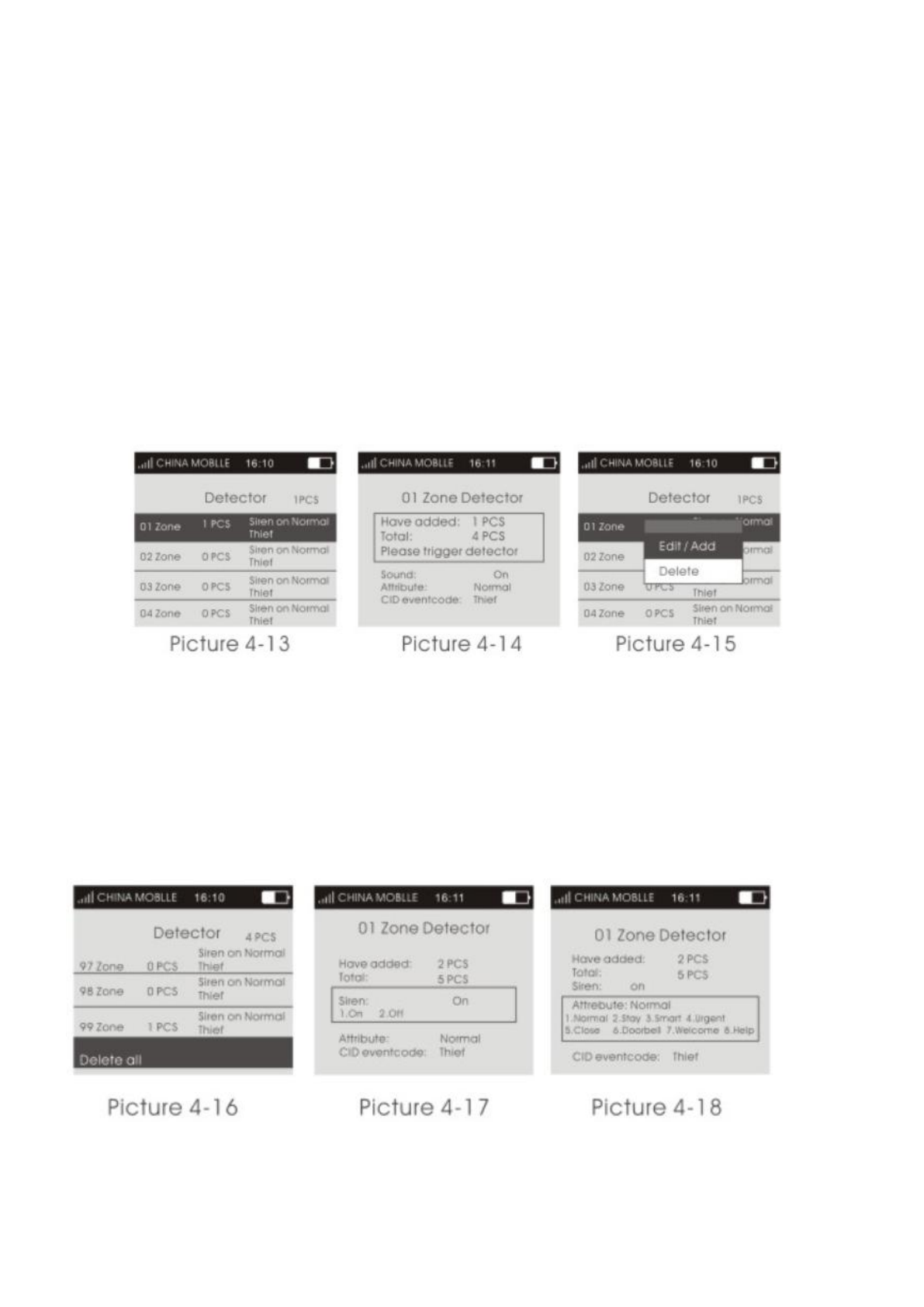
On accessories manage page, as shown in picture 4-7. Press key【UP/DOWN】to select Detector, then press key【OK】
or number 2 directly to enter detector page, as shown in picture 4-13. There are 99 zones in the page, and it displays the
number of detectors learned,siren state, event code, and zone attribute in each zone. Press key【UP/DOWN】to select zone
or input number (01-99) by keyboard ( e.g. Study No. 1 detector, then input 01, study No. 22 detector, input 22), then
press key【OK】to enter detector study page as shown in picture 4-14. At this moment, trigger detector to send a signal to
host, host beeps “di” and the number of learned detector add 1 on the screen, which means the detector has been
programmed to the host; If there is wrong voice prompt when triggering detector, and it means that the detector has been
learned to the host already and couldn’t be programmed repeatedly. To learn more detectors, continue to trigger other
detectors. The host can study as most as 99 different detectors.
4.7.2 Delete Detectors
Delete detector in single zone: after entering detector page, press key【UP/DOWN】to select the zones needed to be
deleted, press key【OK】, host will pop up a small menu as shown in picture 4-15. If selecting【Edit/Add】, it can continue
to study detector or set the zone attribute and event code; if selecting【Delete】, host will pop up a confirmation menu,
select【Yes】, press key【OK】to confirm, then all the detectors in the zone be deleted.
Delete all detectors: As shown in picture 4-16, there is Delete All function at the bottom of detector page. Press key
【UP/DOWN】to select this function, then press key【OK】, it will pop up the confirmation menu, then press key【OK】
again to delete all the detectors in all zones.
4.7.3 Call Alarm ON/OFF
On detector learning page, press key【DOWN】to select zone call alarm ON/OFF as shown in picture 4-17. Press【1】
to select Yes, call alarm ON; Press【2】to select No, call alarm OFF, then press key【OK】to save. If selecting OFF, the
host will not alarm if there is an alert in this zone. The factory default of call alarm is ON.
Note: the siren in this function includes internal and external siren.
4.7.4 Zone Attribute
On detector learning page, press key【DOWN】to move cursor to Attribute as shown in picture 4-18. Press number key to
select: 【1】Normal,【2】Stay,【3】Intelligent,【4】Emergency,【5】Close,【6】Chime,【7】Welcome,【8】Help
Senior, then press key【OK】to save.
4.7.5 Network Event Code
On detector learning page, press key【DOWN】to move the cursor to Event Code as shown in picture 4-19. Press number
key to select: 【1】Medical,【 2】Fire,【 3】Robbery,【 4】Silent Robbery,【 5】Burglar,【 6】Perimeter,【 7】
Gas, then press key【OK】to save.
4.7.6 NO alarm/NC alarm in Wired Zone
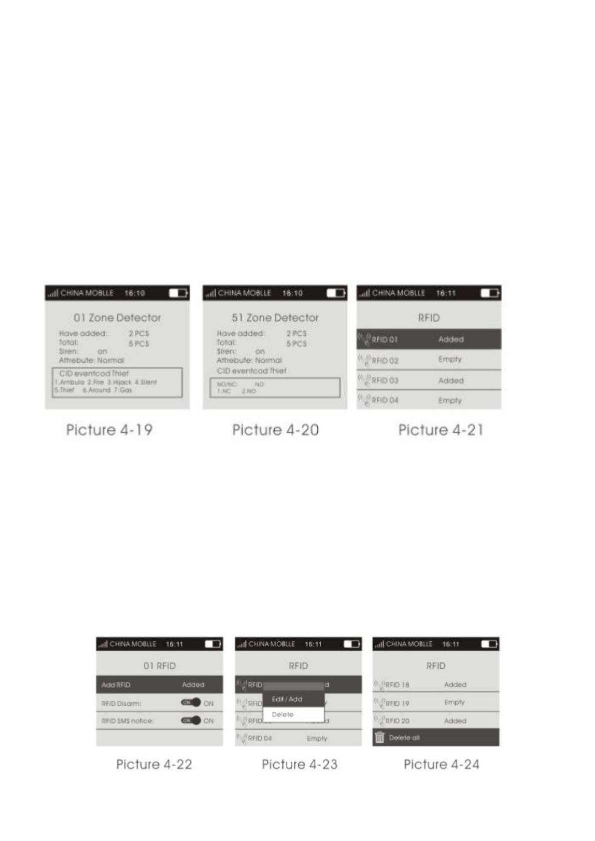
Select wired zones (51-52), and press key【OK】to enter detector learning page, press key【DOWN】to move the cursor
behind【NO/NC】as shown in picture 4-20, and press【1】to select NC alarm; 【2】to select NO alarm, then press key
【OK】to save. The factory default is NO.
4.8 Access Card
4.8.1 Study Access Card - 125KHz
On accessories manage page, as shown in picture 4-7. Press key【UP/DOWN】to move the cursor behind【Access Card】,
then press key【OK】or number 3 directly to enter access card page, as shown in picture 4-21. There are 20 zones in the
page, and only one access card can be learned in one single zone. Press key【UP/DOWN】to select zone and the press key
【OK】to enter access card study page as shown in picture 4-22. At this moment, put the access card on the host card
reader location, host will beep “di” if the card be learned successfully, and the “unlearned” displayed on the screen will
change to “learned”; If user continues to learn access card in the zone has been learned, host will prompt wrong voice,
and it flashes “do not learn” on the screen; If user programs the access card being learned to the zone unlearned, host will
also prompt wrong voice, and it flashes “re-code” on screen, which means the access card can’t be programmed
repeatedly. The host could learn as much as 20 different access cards.
4.8.2 Delete Access Cards
Delete access card in single zone: after entering access card page, press key【UP/DOWN】to select the zones needed to be
deleted, press key【OK】, host will pop up a small menu as shown in picture 4-23. If selecting【Edit/Add】, it can change
the set of【Read Card to Disarm】; if selecting【Delete】, host will pop up a confirmation menu, select【Yes】, press key
【OK】to confirm, then the access card in this zone be deleted.
Delete all access cards: As shown in picture 4-24, there is Delete All function at the bottom of access card page.
Press key【UP/DOWN】to select this function, then press key【OK】, it will pop up the confirmation menu, then press key
【OK】again to delete all the access cards in all zones.
4.8.3 Read Card to Disarm
On access card learning page, press key【DOWN】to move the cursor behind【Read Card to Disarm】, then press menu
key to switch ON or OFF, press key【OK】to save. If selecting ON, the access card can disarm the host. The factory
default is OFF.
4.9 Wireless Strobe Siren
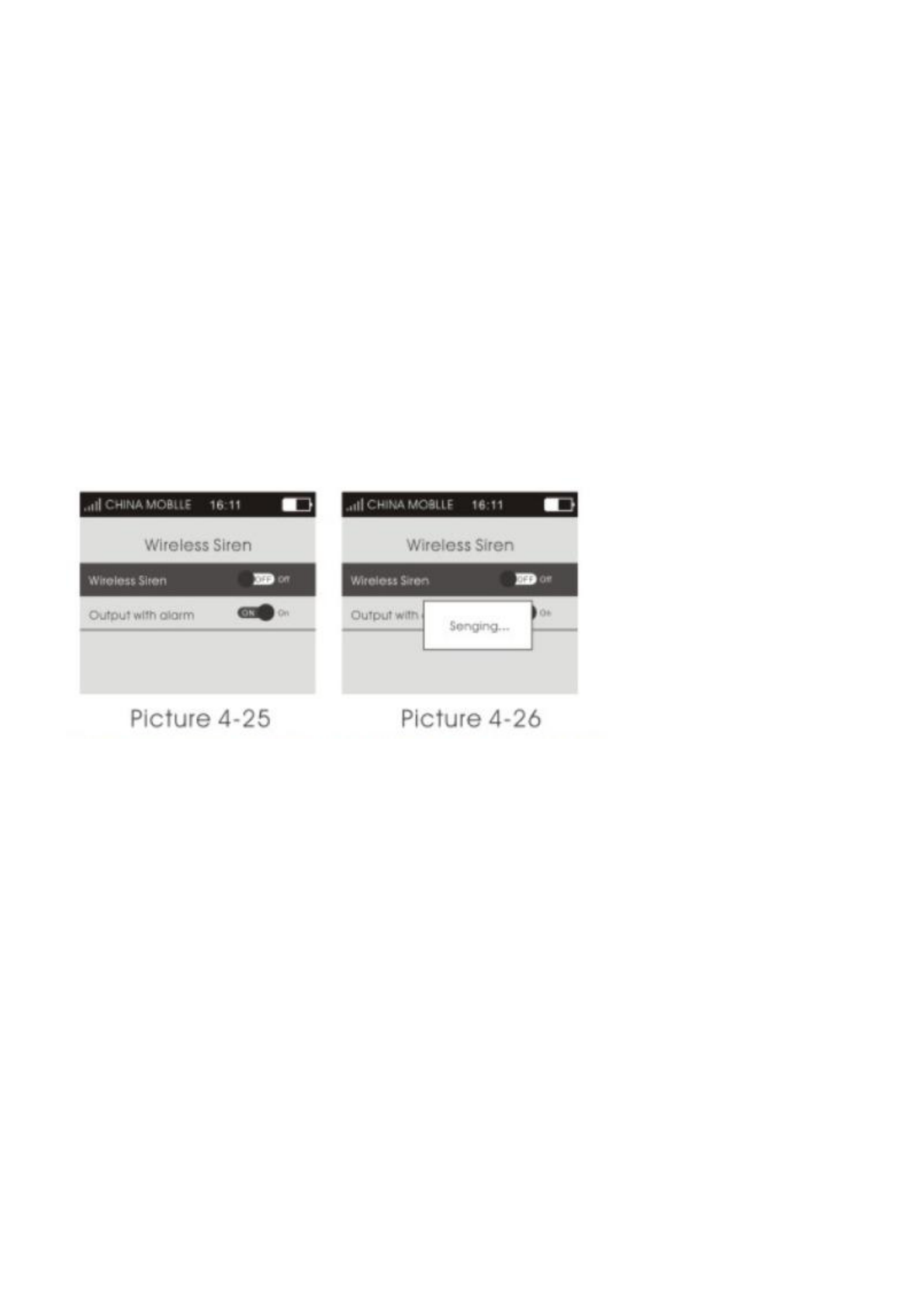
On accessories manage page as shown in picture 4-7. Press key【UP/DOWN】to move cursor behind【Wireless Strobe
Siren】, then press key【OK】or input number 4 directly to enter wireless strobe siren page, as shown in picture 4-25.
4.9.1 Code Match between Host & Wireless Strobe Siren
Code Match Method: In strobe siren standby mode, long press key SET until the alarm indicator lit
constantly to enter learning state; Then on wireless strobe siren page, press menu key to switch【Wireless
Strobe Siren】ON or OFF, host will send signal as shown in picture 4-26; wireless strobe siren will beep twice and
indicator flashes twice after receiving the signal, which means the code match successfully, then press the SET key of
strobe siren to exit the learning state.
Check the Success of Code Match: after wireless strobe siren exit learning state, press menu key to
switch【Wireless Strobe Siren】ON or OFF, if it’s OFF, strobe siren will beep “di di”; if it’s ON, siren will alarm siren,
which means the host match code successfully with wireless strobe siren.
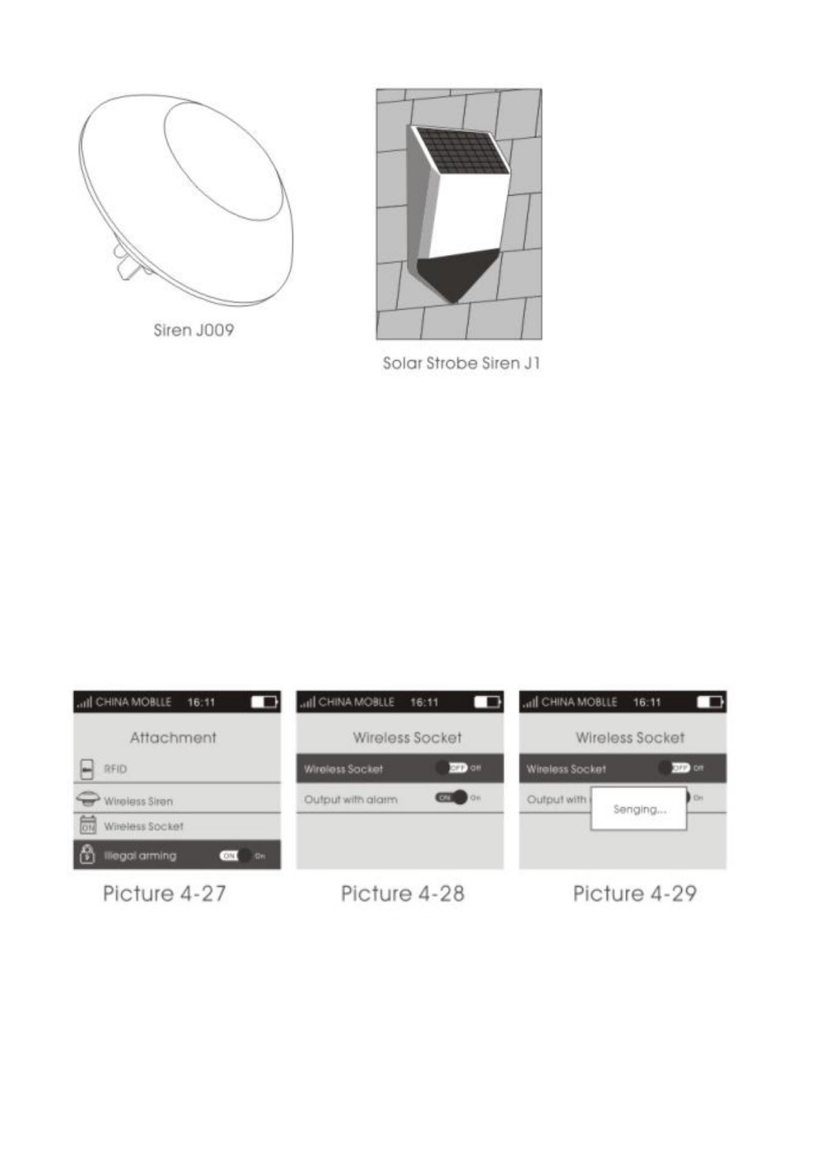
Solar Strobe Siren J1
4.9.2 Alarm Siren
On wireless strobe siren page, press key【DOWN】to move the cursor behind【Alarm Siren】, press menu key to switch
ON or OFF, then press key【OK】to save. The factory default is ON.
When【Alarm Siren】is ON, if host alarms, the wireless strobe siren learned will alarm as well. After disarm or host alarm
ends, strobe siren will stop alarm.
When【Alarm Siren】is OFF, if host alarms, the wireless strobe siren learned will not alarm siren.
4.10 Wireless Alarm Linkage Switch
On accessories manage page, as shown in picture 4-27. Press key【UP/DOWN】to move the cursor behind【Wireless
Alarm Linkage Switch】, as shown in picture 4-27, then press key【OK】or number 5 directly to enter wireless alarm
linkage switch page, as shown in picture 4-28.
4.10.1 Code Match between Host and Smart Socket
Code Match Method: In smart socket standby mode, long press key SET for 5s until the socket indicator
light turns out to enter learning state; Then on wireless alarm linkage switch page, press menu key to
switch【Wireless Alarm Linkage Switch】ON or OFF, host will send signal as shown in picture 4-29; smart socket
indicator light flashes twicel, which means the code match successfully, then press the SET key of smart socket to exit
the learning state.
Check the Success of Code Match: after smart socket exit learning state, press menu key to switch

【Wireless Alarm Linkage Switch】ON or OFF, if it’s OFF, smart socket lit RED; if it’s ON, socket lit BLUE, which
means the host match code successfully with smart socket.
4.10.2 Alarm Linkage
As shown in picture, on wireless alarm linkage switch page, press key【DOWN】to move the cursor behind【Alarm
Linkage】, press menu key to switch ON or OFF, then press key【OK】to save. The factory default is ON.
When【Alarm Linkage】is ON, if host alarms, the smart socket learned will close automatically; After disarming or host
alarm ends, it turns off automatically.
When【Alarm Linkage】is OFF, if host alarms, the smart socket learned will not close automatically.
Chapter Five Installation and Usage of Detectors
5.1 Installation and Use of Door Sensor
Door sensor is used in magnetic induction of close and open state, and is consisted of transmitter and magnetic. It can be
installed on doors, windows or any object that can be closed and opened. When transmitters is separated with magnetic,
door senser will send alarm signal to alarm panel, and host begins alarm siren.
The door contact should be installed on the movable door. Firstly, clean the corresponding position, and take out wireless
door contact , then put on the double faced adhesive. The installation should note the items below:
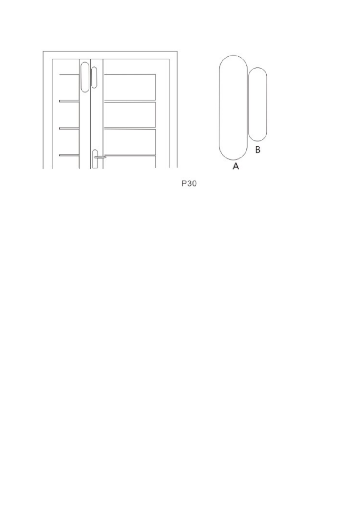
1.The door sensor part A (transmitter) and part B (magnet) should be installed separately, that is, A on fixed door frame
and B on movable door. ( the side with lights of transmitter should correspond with the magnet )
2. A and B should in the same vertical line and the distance between A and B should not greater than 1 cm.
3. After the installation, the indicator light flashes for 1s as the door open, that means the door sensor is installed
successfully.
4.The indicator light lit for 1 second, means alarm. The indicator in constant light is a suggestion of power lack.
5.A, B can also be reinforced by screws, (A: remove the bottom cover, then screw in the bottom, buckle the cover to the
bottom; B can be directly fixed on the screw back.)
5.2 Installation and Use of PIR Motion Detector
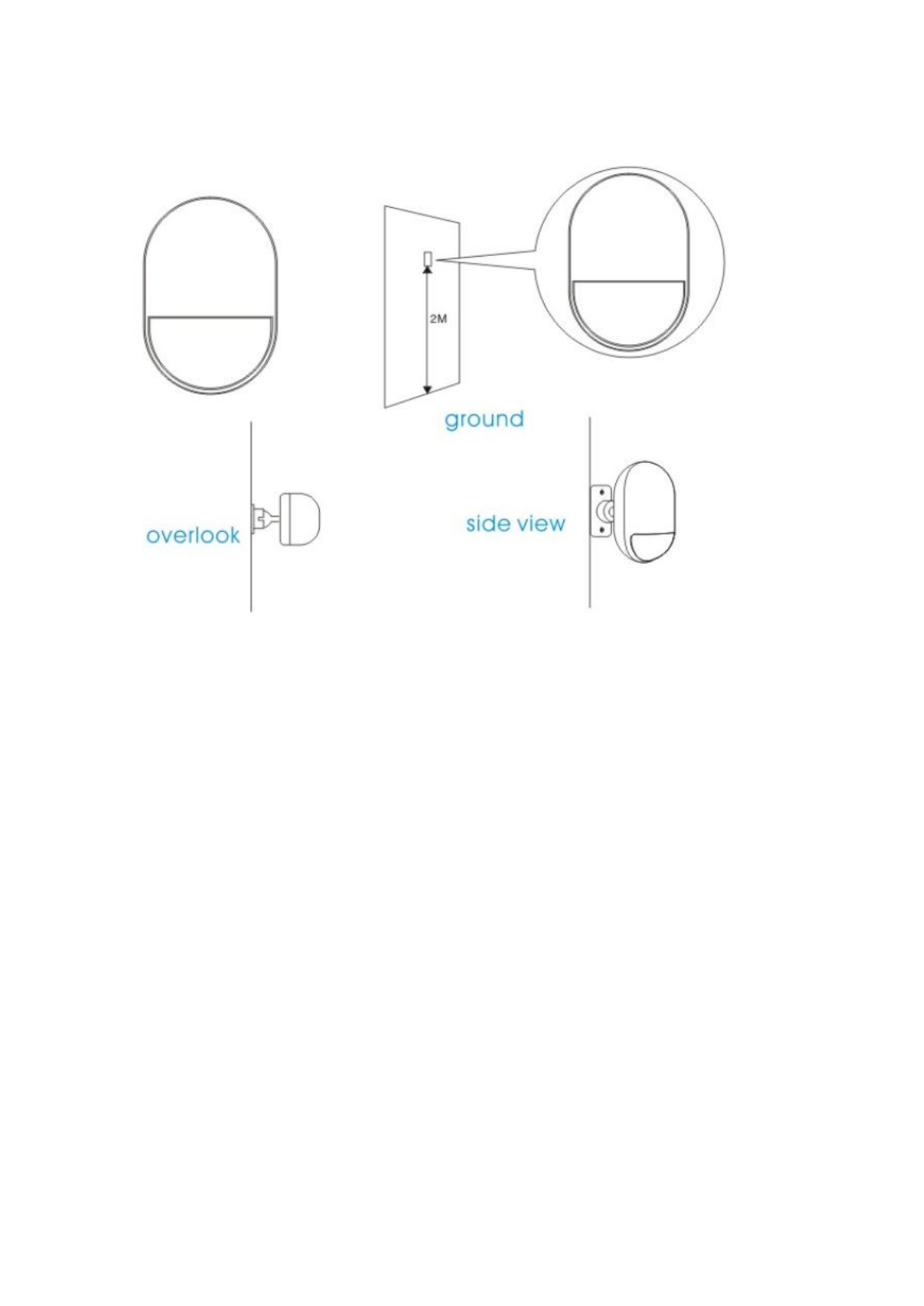
Before use, make sure the power switch of PIR motion sensors is ON. Installation height is about 2.2 meters above
ground and it should be installed in the corner of the room to get the best detection range and should form a certain angle
with the indoor walking line at the same time ( the 90 degree angle with people walking direction is best for detection)
Installation:
Remove the supplied mounting bracket, press the bracket to the slot in the detector bottom. Find the base and reinforce it
with two screws in the wall. Press the PIR with bracket into the center hole of base. and then adjust the best angle of
detecting. (This method is suitable for project installation)
Attention:
1.The detector should not face the outside of window directly.
2. Within coverage of detection, there should be no any big objects for obstruction.
3. There should be no two infrared detectors in the same space as they will possibly intervene with each other.
4.Avoid facing window, cooling or warming machines, stoves, or other appliances that cause the temperature changing
sharply and thus cause false alarm.
5. Infrared detector are indoor use and couldn’t be used outdoor.

Chapter Six Troubleshooting
Troubleshooting
Reasons
Methods
3, Can’t remote operate
1、input wrong password
1、Correct password or change to a new
password or restore to factory default
4, no ISD recorded voice
prompt when alerting
ISD Voice prompt un-recorded
Record it again according to user manual
5, remote controller not
work
1. coding unmatched with the
host
2. insufficient power
3. battery pieces poor contact or
corroded
4. unmatched with host
1. re-coding
2. change battery of the same type
3. eliminating the dirt on the pieces caused
by corrosion
4. contact the local dealer to change the
matched remote controller
6, PIR sensor not work
1. coding unmatched with the
host
2. insufficient power
3. battery pieces poor contact or
corroded
4. unmatched with host
1. re-coding
2. change battery of the same type
3. eliminating the dirt on the pieces caused
by corrosion
4. contact the local dealer to change the
matched remote controller
7, siren no sound
1、internal siren is OFF
1、 Open internal siren
8, The transmitter distance
for host is shortened
1.a nearby emitter is sending
code
2. host receiver stop work
3.standby battery of the host
insufficient
1.find the interfering source and eliminate
it
2.post back to the factory for amendment
3.check host power whether plugged well
9, Host no Voice prompt
1、voice prompt function is OFF
1、open voice prompt function
FCC Warning:
This equipment has been tested and found to comply with the limits for a Class B digital device, pursuant
to part 15 of the FCC Rules. These limits are designed to provide reasonable protection against harmful
interference in a residential installation. This equipment generates uses and can radiate radio frequency
energy and, if not installed and used in accordance with the instructions, may cause harmful interference
to radio communications. However, there is no guarantee that interference will not occur in a particular
installation. If this equipment does cause harmful interference to radio or television reception, which can
be determined by turning the equipment off and on, the user is encouraged to try to correct the
interference by one or more of the following measures:
-Reorient or relocate the receiving antenna.
-Increase the separation between the equipment and receiver.
-Connect the equipment into an outlet on a circuit different from that to which the receiver is connected.
-Consult the dealer or an experienced radio/TV technician for help.
This device complies with part 15 of the FCC Rules. Operation is subject to the following two conditions:
(1) This device may not cause harmful interference, and (2) this device must accept any interference received,
including interference that may cause undesired operation.