KING 10157V10 Vu Qube Remote Control User Manual VQ V10 Manual 05
King Controls Vu Qube Remote Control VQ V10 Manual 05
KING >
Users Manual Revised
Installation and Operating Manual
Made in the USA
TM
Mobile Satellite TV Antenna
With FastFind Remote
Vu Qube V10_04
2
1. INTRODUCTION and BACKGROUND................................................ 3
2. COMPENT OVERVIEW and SPECIFICATIONS................................. 4
3. FCC USER’S INFORMATION………………………………………...….5
3. INSTALLATION .............................................................................. 6-8
4. OPERATION ....................................................................................... 9
6. TROUBLESHOOTING ........................................................................ 10
7. MAINTENANCE .................................................................................. 10
8. LIMITED WARRANTY ........................................................................ 10

Vu Qube V10_04
3
Introduction
Congratulations on your purchase of the Vu Qube V10. The Vu Qube V10 is equipped with a
FastFind remote enabling you to quickly position the Vu Qube antenna from inside your
vehicle. The Vu Qube V10 is compatible with any service provider such as DIRECTV ®, DISH
Network ® or Bell ExpressVu.
This manual includes a:
• Brief background on satellite television
• Components overview
• Installation diagrams and instructions
• Operating Instructions
Technical Support
Phone: (866) 802-2228
Email: info@vuqube.com
Web: www.vuqube.com
Background
Satellites used for television signals are 22,300 miles (37,000 km) above the earth’s equator.
The purpose of the Vu Qube is to acquire the signal traveling that great distance and transmit
the signal to your digital receiver in your vehicle so you can watch TV anywhere you park.
Satellite television, like other communications relayed by satellite, starts with a transmitting
antenna located at an uplink facility on Earth. The uplink dish is pointed toward a specific
satellite and the uplinked signals are transmitted. The signal transmitted to the satellite is
within a specific frequency range and is received by one of the transponders tuned to that
frequency range aboard that satellite. The transponder then transmits the signals back to Earth
but at a different frequency band (to avoid interference with the uplink signal). The leg of the
signal path from the satellite to the receiving Earth station, in this case the Vu Qube, is called
the downlink.
The downlinked satellite signal, quite weak after traveling the great distance is received by the
Vu Qube antenna, which reflects the weak signal to a focal point that gets transferred to a
feedhorn. The receiving antenna must have a clear view, without obstruction, of the
southern sky to maximize signal acquired. This signal is then amplified and converted by
the LNBf (Low-noise block converter feed) to a signal that is sent via a co-axial cable to the
receiver. Once the signal is transmitted from the Vu Qube to your receiver, you can enjoy all of
your programming in your vehicle just like at home!
A Quick Reference guide is included with Operating Instructions & Elevation information
that we suggest you keep with the Vu Qube Controller or near your Satellite TV receiver.
The Satellite Broadcast Market is changing and expanding. The information in this
manual was accurate at the time of printing. If the Vu Qube does not operate as shown
in this manual, please call Wallace Technologies at 1-866-802-2228 or email us at
info@vuqube.com.
Vu Qube V10_04
4
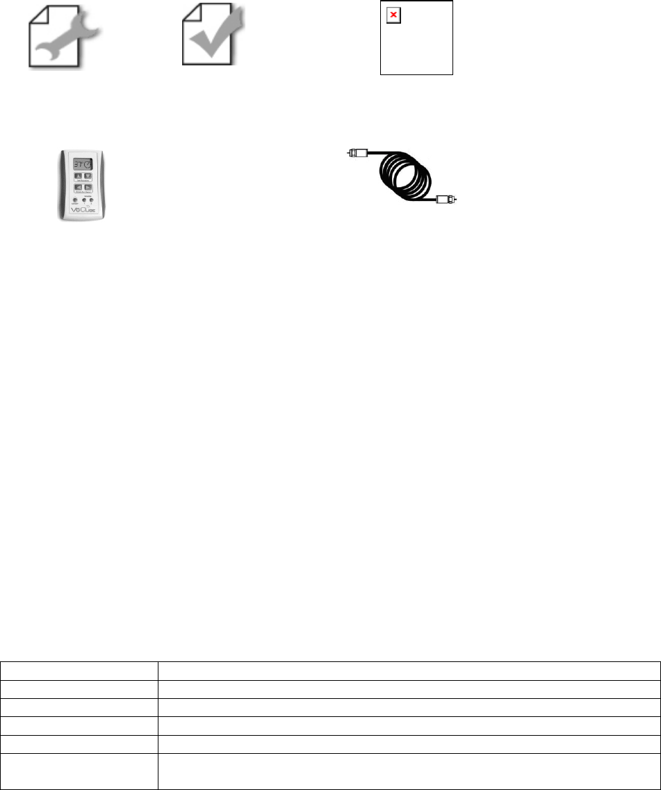
Vu Qube V10 Component Overview
Manual Quick Reference Guide Vu Qube Antenna
Vu Qube FastFind Remote RG6 Coaxial
Cable (20’)
Mounting Kit (Purchased Separately)
Kit shown is Model Number 31100
***You will need to supply your own fasteners to attach a Vu Qube bracket to your vehicle. Depending on
the Cab material, fasteners such as lag screws, well nuts, sheet metal screws, toggle bolts and T
anchors may be used, and should always be used in combination with compatible sealant to
environmentally seal the holes after installation.***
Items needed to watch TV
Satellite TV service
Satellite TV receiver
Television
Tools needed for installation
Drill and drill bits
Tape measure
Screw drivers and Wrenches
Adhesive sealant (compatible with vehicle material)
Fasteners to secure Components and wiring
SPECIFICATIONS
Height: 17.5”
Width: 16”
Weight: 10.5 lbs
Range: US/Southern Canada
Compatibility: DirecTV, Dish Network, Bell ExpressVu, Free-to-air receivers
Operating Temp: May experience difficulty positioning antenna when temperatures are
below 0°F
Vu Qube V10_04
5
FCC User Information
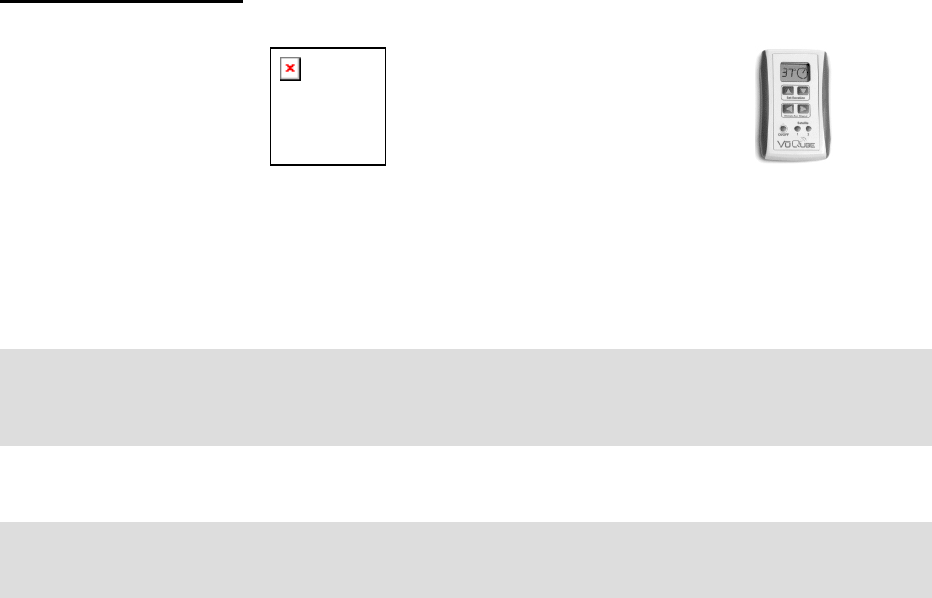
Main Components
Vu Qube V10 Antenna Vu Qube V10 Remote
Part #: VQV10
FCC ID: UUM10156V10
IC: 6873A -10156V10
This devise complies with Part 15 of the FCC rules.
Operation is subject to the following two conditions:
1) This devise must not cause harmful
interference, and 2) This devise must accept
interference received including interference that
may cause undesired operation.
Part #: VQV10R
FCC ID: UUM10157V10
IC: 6873A -10157V10
This devise complies with Part 15 of the FCC rules.
Operation is subject to the following two conditions:
1) This devise must not cause harmful
interference, and 2) This devise must accept
interference received including interference that
may cause undesired operation.
The Vu Qube V10 and Vu Qube V10 remote have been tested and found to comply with
the limits for a Class B digital device, pursuant to part 15 of the FCC Rules. These limits
are designed to provide reasonable protection against harmful interference in a
residential installation. This equipment generates, uses, and can radiate radio
frequency energy and, if not installed and used in accordance with the instruction, may
cause harmful interference to radio communications. However, there is no guarantee
that the interference will not occur in a particular installation. If this equipment does
cause harmful interference to radio or television reception, which can be determined by
turning the equipment off and on, the user is encouraged to try to correct the
interference by one or more of the following measures:
• Reorient or relocate the receiving antenna.
• Increase the separation between the equipment and the receiver.
• Connect the equipment into an outlet on a circuit different from that to which the
receiver is connected.
• Consult the dealer or an experienced radio/TV technician for help.
Please do not co-locate the Vu Qube V10 and Vu Qube V10 remote with other
transmitters.
Please note that changes or modifications to the Vu Qube V10 or Vu Qube V10
remote not expressly approved by Wallace Technologies could void the
p
urchaser’s or user’s authorit
y
to o
p
erate this e
q
ui
p
ment.
Vu Qube V10_04
6
Installation
Overview of Installation
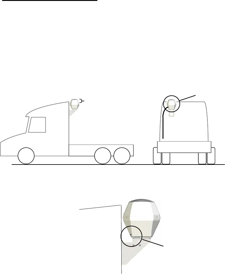
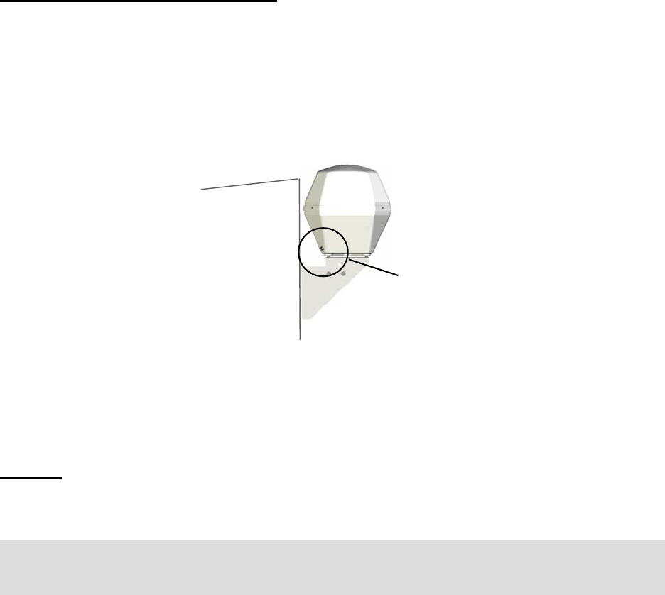
• The Vu Qube is designed to be mounted to a vehicle (Figure 1).
• It is recommended to install the Vu Qube with a minimum of 4” of the top cover above
the highest point of the cab or air shield (Figure 1) and away from interfering objects like
smoke stacks.
• The coaxial cable needs to enter the Cab to be connected to the satellite receiver.
Figure 2. Face connections for wiring towards the back of the cab.
Figure 1. It is recommended to have a minimum of 4” of the VuQube above the highest point on the cab, including the air shield.
It is also recommended to be as far away as possible from any object that may obstruct direct line of sight of the antenna to the
southern sky. Such interfering items may include air-conditioner units, logistic devices and brackets, beacons and smoke stacks.
Mounting Location
• Choose mounting position with least
amount of obstruction (i.e. away
from smoke stack).
• Make sure to have space to run
coaxial cable.
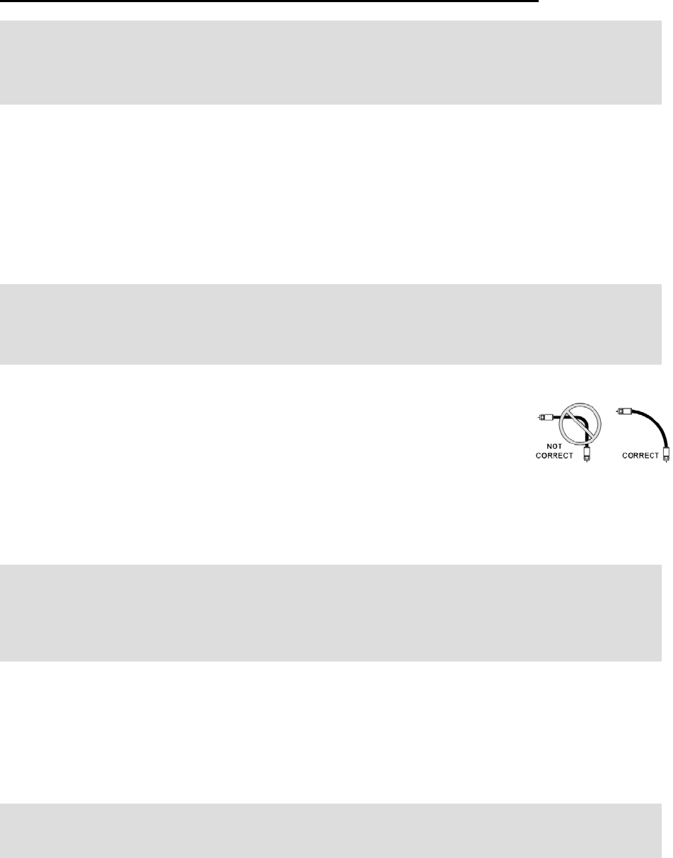
• Make sure when you run the wires
that there are not any sharp bends.
Be sure to mount with
minimum 4” above cab
Back of cab Coaxial Cable connection
• Face towards back of the cab.
• Position on side you will run coaxial
cable.
Vu Qube V10_04
7
Installation
Mounting the bracket and selecting location to run wiring
1) Select and mark both area on back of Cab to mount the bracket AND location to run
coaxial cable from the Vu Qube to the inside of the Cab.
• Be sure at least 4” of Vu Qube is above the highest part of the roof so that adequate
signal can be received by the antenna. The clearance of the Vu Qube is important
because the antenna requires a direct line of site to the satellite in the southern sky to
acquire a signal.
• The Vu Qube requires a 16” wide space to be mounted.
• Make sure you allow enough space for the wiring so that the co-axial
cable does not have a sharp bend.
• It is best to select a position on the rear of the cab free from
obstruction. Obstructions like smoke stacks, brackets, and air-conditioning units may
interfere with satellite signal or prevent the satellite signal from reaching the Vu Qube.
2) Drill holes for mounting bracket with proper size depending on fasteners used.
3) Mount bracket to cab using fasteners.
4) Seal holes with a sealant compatible with cab, faring, or air shield material, depending
on where Vu Qube is mounted.
5) Drill hole to pass the harnesses inside the vehicle.
Note: It is an option to run the wiring down the back of the cab and up into the cab through
an access bay.
NOTE: If you are unable to install the Vu Qube 4” above the cab due to height restriction,
install with the maximum available clearance. With less of the Vu Qube top cover above the
Cab, there may be difficultly acquiring satellite signal in the Northeastern US (Maine, New
Ham
p
shire, Vermont and Massachusetts
)
.
NOTE: Instructions for mounting the Vu Qube is illustrated using Mounting Bracket Kit part
number 31100. This Mounting Bracket Kit and others were designed specifically to mount
the Vu Qube to the back of a truck cab. Please contact Wallace Technologies, LLC (866-
802-2228) regarding other bracket options.
Note: The installer is responsible for determining the most appropriate fastener to secure
the bracket to the cab. Depending on the Cab material, fasteners such as lag screws, well
nuts, sheet metal screws, toggle bolts and T anchors may be used. Fasteners should always
be used in combination with compatible sealant to environmentally seal the holes after
installation.
Vu Qube V10_04
8
Installation
Mounting Antenna to Bracket
1) Place Vu Qube on bracket.
• Coaxial cable connections from the Vu Qube (Figure 2) should be positioned toward the
Cab (front of the vehicle) and to side where hole is drilled to run wires inside the cab.
Figure 2. Face connections for wiring towards the back of the cab.
2) Secure Vu Qube to bracket by fastening with Nuts provided. Be sure to tighten nuts
adequately to ensure Vu Qube is securely in place.
Wiring
1) Connect 20’ coaxial to Vu Qube.
2) Pass 20’ coaxial cable through hole previously drilled.
3) Connect coaxial cable from Vu Qube to SATELLITE IN port on Satellite Receiver.
4) Make sure Satellite Receiver is connected to TV per manufactures instructions.
Note: It is an option to run the wiring down the back of the cab and up into the cab through
an access bay.
Back of cab Coaxial Cable connection
• Face towards back of the cab.
• Position on side you will run coaxial
cable.
Vu Qube V10_04
9
Vu Qube V10 Operation
• IMPORTANT! CLEAR LINE OF SIGHT for Vu Qube Antenna to the SOUTHERN
SKY REQUIRED. Physical obstruction (i.e., smokes stacks, buildings, trees,
telephone poles, etc.) can block the satellite signal from reaching the antenna.
• Satellite TV and receiver technology are constantly changing. If you experience
difficulty contact (866) 802-2228.
Finding the Satellite and Acquiring a Signal
1. Determine Dish Elevation
Options: Enter Zip Code in System Set-up on receiver
-or-
Use Quick Reference Maps to estimate Elevation
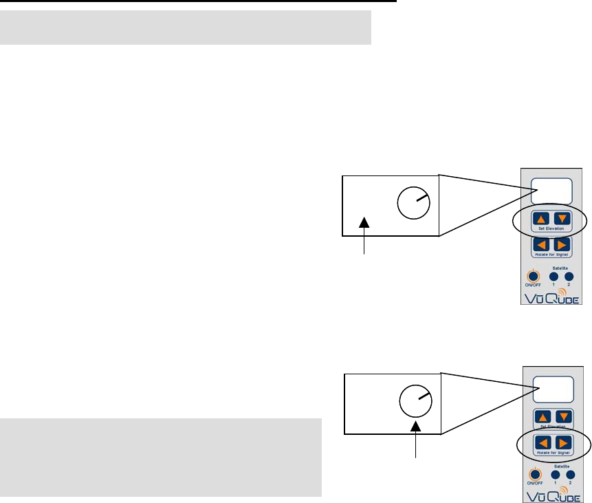
2. Position Antenna to proper Elevation using
Up/Down arrows on Vu Qube Remote.
3. Go to the signal meter screen on TV.
Choose transponder number: Dish Network #11
DirecTV #19
4. Rotate Antenna using Left/Right arrows
on Vu Qube remote until signal appears
on Signal Meter screen.
5. Fine tune and maximize signal using all 4 arrows.
Satellite Position Memory
TO STORE POSITION: Hold down either the Satellite 1 or Satellite 2 button for at least 2.5
seconds. The LCD will show “P1” or “P2” when button is released.
TO RECALL POSITION: Hold down either the Satellite 1 or Satellite 2 button for less than 2.5
seconds. The LCD will “r1” or “r2”.
TO CANCEL RECALL: Press any arrow button to stop moving to a stored position.
NOTE: When rotating line is straight up,
the antenna is pointing directly at the
coaxial connector on the Vu Qube.
NOTE: Satellite Receiver and TV MUST be ON
37°37°
This number indicates Elevation
37°37°
Line moves to indicate
Rotating Antenna
Vu Qube V10_04
10
Troubleshooting
If you cannot lock-on to the correct satellite, it is most likely that an object is blocking
the signal. If this is the case, move the vehicle to have an unobstructed view of the
southern sky.
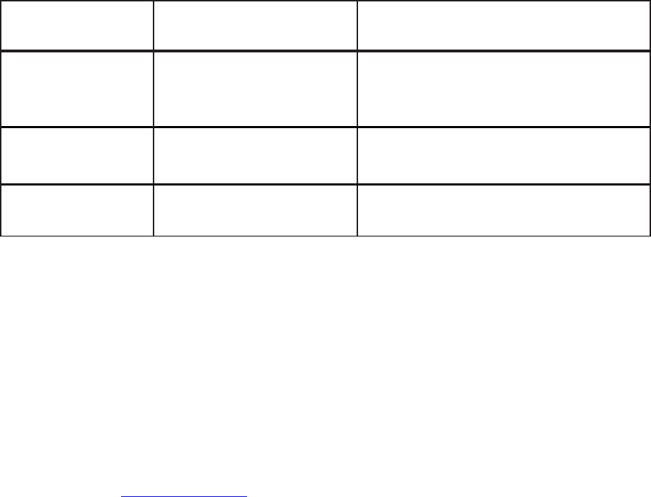
ERROR CODES Problem ACTION
E0 Remote is unable to send
commands to Antenna
• Make sure RECEIVER is turned ON
• Make sure Coax from Antenna is
attached to Receiver
• Move remote closer to Antenna
E1 Remote is unable to receive
response from Antenna Move remote closer to Antenna
E2 Miscommunication between
remote and antenna Call Wallace Technologies @ 866-802-2228
Maintenance
The Vu Qube has been designed to be maintenance and trouble free. For optimum signal
strength, keep the cover clean from dirt, bugs, and other debris. Periodic washing of the top
cover with mild soap and water is recommended.
If you plan on storing your vehicle for long periods of time, it is recommended that the system
be put through a search procedure on a quarterly basis to keep all moving parts in good
working order.
If you have any comments or questions, please contact Wallace Technologies at (866) 802-
2228, or email at info@vuqube.com.
Limited Warranty
Every Vu Qube is thoroughly inspected and tested before leaving the factory and is covered
by a two year parts and one year labor limited warranty from the date of original purchase.
This warranty does not cover installation and external wiring or refurbished units.
Should any trouble develop during the warranty period, contact Wallace Technologies. Only
Wallace Technologies and certified dealers are authorized to perform warranty evaluations
and repairs.