KISCOMM KIS900W-4CH UHF-Band RFID Reader User Manual
KISCOMM Co.,Ltd. UHF-Band RFID Reader Users Manual
KISCOMM >
Users Manual

The Frequency Hop Spread Spectrum UHF RFID
4 channel Reader system in 800/900 MHz ISM band
KIS900W-4CH
Ver. 2.12
User Manual
June 2005

KIS900W-4CH User Manual Page 2 of 21
Federal Communications Commission (FCC)
Interference Statement
This device complies with Part 15 of FCC rules. Operation is subject to the following two conditions:
This device may not cause harmful interference.
This device must accept any interference received, including interference that may cause undesired
operations.
Caution : Any changes or modifications in construction of this device which are not expressly
approved by the party responsible for compliance could void the user's authority to operate the
equipment.
Notice 1
Notice 2
Notice 3
Rev.2.12
Shielded RS-232 cables are required to be used to ensure compliance with FCC
Part 15, and it is the responsibility of the user to provide and use shielded RS-232
cables.
The manufacturer is not responsible for any radio or TV interference caused by
unauthorized modifications to this equipment. Such modifications could void the
user's authority to operate the equipment.
This equipment has been tested and found to comply with the limits for a Class A digital device,
pursuant to part 15 of the FCC Rules. These limits are designed to provide reasonable protection against
harmful interference when the equipment is operated in a commercial environment. This equipment
generates, uses, and can radiate radio frequency energy and, if not installed and used in accordance with
the instruction manual, may cause harmful interference to radio communications. Operation of this
equipment in a residential area is likely to cause harmful interference in which case the user will be
required to correct the interference at his own expense.

KIS900W-4CH User Manual Page 3 of 21
Table of Contents
Federal Communications Commission (FCC) Interference Statement 2
1. GLOSSARY. ................................................................................................................4
2. INTRODUCTION. .........................................................................................................4
3. TECHNICAL SPECIFICATION. ...................................................................................5
4. SUPPLIED GOODS AND ACCESSORIES..................................................................7
5. PUTTING INTO OPERATION......................................................................................8
6. CABLE CONNECTIONS............................................................................................11
7. TROUBLE SHOOTINGS............................................................................................12
8. NOTICE......................................................................................................................13
9. WARNINGS AND CAUTIONS ...................................................................................14
10. ORDERING AND LABEL INFORMATION.............................................................15
11. APPENDIX A. KISCOMM UHF RFID CONTROLLER’S COMMANDS * ..............16
12. APPENDIX B. KISCOM RFID READER CONFIGURATION BYTE LISTING.....19
Rev.2.12

KIS900W-4CH User Manual Page 4 of 21
1. GLOSSARY.
dB Decibels;
dBi Antenna gain in dB relative to isotropic antenna;
EIRP Effective Isotropic Radiated Power;
EPC Electronic Product Coding;
ERP Effective Radiated Power;
FH Frequency Hopping;
RFID Radio Frequency Identification;
RTF Reader Talks First (Protocol);
UHF Upper High Frequency (Band);
2. INTRODUCTION.
This User Manual is destined for studying of the KISCOM Frequency Hop Spread Spectrum UHF
RFID Scanner 4 channel System in 800/900 MHz ISM band KIS900W-4CH employment.
The System is designed to read an EM 4222 (EM Marine) and Philips UCODE EPC 1.19
SL3ICS31 01 chips based UHF transponders.
It is equipment for industrial applications especially well suited for large reading distance and
multiple Tags with the Random delay Time reply on power Anticollision protocol for EM 4222.
System supports OID Radio Frequency Identity Protocol for communications at 860 MHz – 960
MHz Generation 2 Identity Tag (Class 1).
The wide ranges of applications for this equipment includes
• Factory automation
• Electronic toll collection (ETC)
• Railway, car identification and tracking
• Inter modal container identification
• Asset identification and tracking
• Item management for retail, health care, and logistics applications
• Access control
• Animal identification
Typical reading range is between 30 cm to 6 m depending on the Reader model, type of antenna,
used transponder and environment.
Rev.2.12

KIS900W-4CH User Manual Page 5 of 21
3. TECHNICAL SPECIFICATION.
3.1. KIS900W-4CH RFID reader system is used for identifying/reading transponders based on
EM 4222 chip and Philips Read/write SL3ICS31 01 chip.
3.2. KIS900W-4CH RFID reader system supports multiple tag identification processes using
Anticollision protocol.
3.3. KIS900W-4CH RFID reader system supports UCODE EPC Philips Tag’s user memory
writing protocol.
3.4. KIS900W-4CH reader system have five frequency band modifications:
Korean regulation 910 – 914 MHz
(18 channels, 200 kHz spacing Frequency
Hope)
USA ISM Frequency band 902 – 928 MHz
(63 channels, 400 kHz spacing Frequency
Hope);
Singapore Frequency band 923 – 925 MHz
(8 channels, 200 kHz spacing);
EUROPE and Far East Frequency band 800 MHz 1 channel inside 869,4 – 869,65 MHz
South Africa 915.3 MHz
3.5. Carrier frequency stability 1X10⁻⁵
3.6. Radio power output 1 W ERP (Korean Band)
4 W EIRP (USA ISM Band)
4 W EIRP (Singapore Band)
0,5 W ERP (European Band)
2 W ERP (South Africa Band)
3.7. Read range (1W) 5 meters (Typically read range depends on
Reader environment and the used tag)
3.8. Transponder specification
- based on EM 4222 chip, read only;
Transponder Activation: Random delay Time reply on power;
Tag ID 64 bit
Tag bit data rate
Data Rate Operational modes Value 1 64 kbit/s (chip V1, V2)
Value 2 256 kbit/s (chip V3, V4, V5)
Modulation /Coding AM/time pulse position
- based on SL3ICS31 01 chip, read/write:
Transponder Activation: RTF (Reader Talks First);
Tag ID 64 and 96 bits EPC number support;
Rev.2.12
256 bits user memory.

KIS900W-4CH User Manual Page 6 of 21
Reader to Tag
data rate 40 kbps
Modulation /Coding AM/Manchester encoding
Tag to Reader
data rate 40 kbps
160 kbps
Modulation /Coding AM/FM0 encoding
3.9. Interfaces:
Serial RS232 / RS422 optional,
9600, 19200, 38400 115200 baud; 8 data; no parity; 1 stop bit
10BaseT Ethernet Port; Optional
3.10. Power Supply Input DC Voltages 5 V / 1,5 A
3.11. Operating Temperature range -20deg to +50 deg C
3.12. Humidity 5 to 95 % non-condensing
3.13. Dimension 196 (W) x 310 (L) x 42 (H)
3.14. Weight Approx. 1,0 Kg
3.15. Antenna
KIS900-AE
Frequency band 902-928 MHz
Gain <6 dBi
Polarization Horizontal
In band VSWR < 1,2
Dimension (mm) 420 (L) 215 (w) 55 (H)
Weight Approx. 1,5 Kg
KIS900-AN-2H02
Frequency band 902-928 MHz
Gain <6 dBi
Polarization Horizontal
In band VSWR < 1,15
Dimension (mm) 454 (L) 215 (w) 55 (H)
Weight Approx. 1,5 Kg
KIS900-AN-2V02
Frequency band 902-928 MHz
Gain <6 dBi
Polarization Vertical
In band VSWR < 1,15
Dimension (mm) 454 (L) 215 (w) 55 (H)
Weight Approx. 1,5 Kg
Rev.2.12

KIS900W-4CH User Manual Page 7 of 21
4. SUPPLIED GOODS AND ACCESSORIES.
KIS900W-4CH Reader 1
Antenna 1
KIS 900-AE;
Or KIS 900-AN-2H02;
Or KIS 900-AN-2V02
RF Antenna Cable (length 3m) 2
KIS900W-4CH Test S/W & User Manual CD 1
RS-232 serial interface cable 1(Optional)
Power Supply Block PL-050201 1 (Optional)
AC power supply cable 1 (Optional)
Tag Optional
Rev.2.12

KIS900W-4CH User Manual Page 8 of 21
5. PUTTING INTO OPERATION
a) Read please this User manual fully before any installation works.
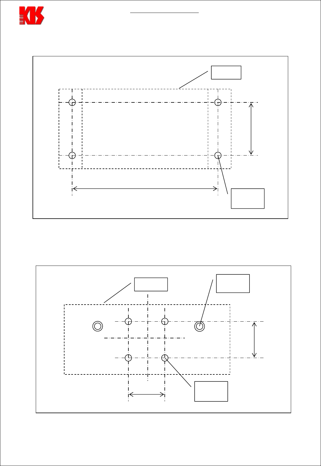
b) Install and fix Reader, Antennas and Power Supply on the wall or another surfaces, where you
will to place and to use equipment. Distance between Reader and Antenna must not be more 3
m RF cable length. The Direction of the Antenna front surface must be in direction on the
wanted reading area.
There are must be used bolt M4 or M5 for Reader mounting. Mounting Bolts placement and
dimension depicted on Figure 1.
There are must be made fore holes for Antenna mounting, as it depicted on Figure 2.
Notice: The antenna must be installed by the professional installer to comply with the safety, electrical and
radiation standards.
The installer should properly configure the output power of transceiver according to related
country regulation requirement and per antenna type.
FCC regulations limit exposure to radio frequency (RF) radiation. To comply with these regulations,
operators of this device must maintain a distance of at least 23 cm. (9.1 inches) from the cover on
the antenna assembly (The cover on the antenna is the dome shaped surface). While the device is
on, the operator’s body and parts of the body such as eyes, hands, or head, must be 23 cm. (9.1 inches) or
farther from the cover of the antenna assembly.
FCC regulations also require that the antenna assembly of this device be installed in accordance with the
installation procedures to allow the operator to comply with the limit.
Use of antennas and accessories not authorized may void the compliance of this product and may result in
RF exposures beyond the limits established for this equipment.
Rev.2.12
KIS900W-4CH User Manual Page 9 of 21
Mounting bolts placement for Reader installation.
Reader
Fig. 1
Mounting Holes placement for Antenna installation.
Fig. 2
270 ~ 290 mm
100 mm
Bolt
p
osition
70 mm
Antenna
70 mm
BNC
Connector
Hole
p
osition
Rev.2.12

KIS900W-4CH User Manual Page 10 of 21
c) Make next cable connections:
• Reader to Antenna using RF cables from the supplied accessories set;
• Reader to PC according to Fig. 1 in section 6 of this manual;
• Reader to Power Supply Block according to Table 1 in section 6 of this manual;
d) Run appropriate software (for example Windows terminal program) on PC.
Please assure the interface is set to the right baud rate (default Reader port parameter: 38000
baud, 8N1).
Establish a connection to the reader and connect reader power supply to power source.
After power on and successful self-test reader send a message, which must to appear on terminal
window (see appendix “KISCOM UHF RFID Controller’s COMMANDS”):
<KISCOM Reader 900RE Started><CR><LF>
Default RS232 interface: 38400 baud, 8 data, no parity, 1stop bit
e) Test the reader with the command described in Command Set Manual.
f) After the device is successfully tested as described above, you can set the reader configuration as
needed. Details how to change the configuration of the reader are described in appendixes
“KISCOM UHF RFID Controller’s COMMANDS” and “KISCOM RFID READER
CONFIGURATION BYTE LISTING”.
Rev.2.12
Last configuration will be stored automatically in reader and used after power turn off.
KIS900W-4CH User Manual Page 11 of 21
6. CABLE CONNECTIONS
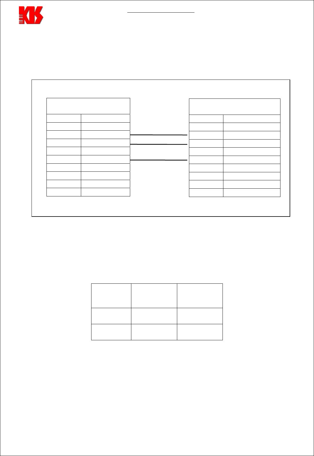
RS-232 Connection cable between Reader and PC depicted on Fig. 1
RS-232 Connection cable between Reader and PC
To PC
9pin Female D Type
Pin N Net
1 NC
2 Receive Data
To Reader DATA
3 Transmit Data
4 NC
5 Signal Ground
6 NC
7 NC
8 NC
9 NC
Fig. 1
The power supply Connector pins out, current for each voltage line of power connector showed in
Table 1.
TABLE 1. The power supply Connector pins out
JR1
Pin N Supply line
Voltage Current
consumption*
1 + 5 V 1,5 A
2 GND
Current consumption* - It is average current in the Table 1, real current may be +- 20 %.
Rev.2.12
9pin Male D Type
Pin N Net
1 NC
2 Transmit Data
3 Receive Data
4 NC
5 Signal Ground
6 NC
7 NC
8 NC
9 NC

KIS900W-4CH User Manual Page 12 of 21
7. TROUBLE SHOOTINGS
Should the reader not work as desired, please check the following:
a) Is the configuration of the reader as wanted?
Check with help of the command W[w].
b) Is the configuration not known, are the baud rates of reader and terminal set different?
Restore the basic setting of the parameters values with command D[d].
Now all parameter values are set to the default values, the reader will work in normal condition.
c) Is the antenna defect or not properly connected?
d) The transponder is not in the active antenna field. Bring the transponder closer to the antenna.
e) Antenna mounting is wrong (for example behind a metal structure).
In such a case, it can happen that the radiated power is reflected by unwanted plate in nearby metal
structures.
Please change antenna position.
f) Although there is no transponder in the active antenna field.
g) Noise from another radio equipment can also reduce the read range. You should try to remove all
source of noise causing devices.
Upper High Frequency fields radiated by other devices interfere with the reader communication: -
power supplies, electrical motors, etc.
Please remove such devices or remove the radiated interfering field by proper grounding if trouble
takes place.
Rev.2.12

KIS900W-4CH User Manual Page 13 of 21
8. NOTICE
a) The device cannot be sold retail, to the general public or by mail order. It must be sold to dealers
or have strict marketing control.
b) Installation of this device should be accomplished only by a qualified RF system Installer
who is :
- Knowledgeable of the use, Installation and configuration procedures and associated RF
components.
- Knowledgeable of each system component’s equipment User and Installation Guide.
- Knowledgeable of the installation and configuration procedures for the site’s.
Infrastructure system and wiring.
- Knowledgeable of the installation procedures, safety, and code requirements for the
site’s antenna, antenna mast, antenna cabling, and installation. KISCOM highly
recommends that the antenna installation be performed by a qualified antenna
installation professional.
c) The intended use is generally not for the general public. It is generally for industry/commercial
use.
Rev.2.12

KIS900W-4CH User Manual Page 14 of 21
9. WARNINGS AND CAUTIONS
! This reader is an active electrical transmission system and radiates in UHF frequency range of
approximately 900 MHz. When connecting a defective or a not suited antenna to the device the radiated
power can be higher than 4 dB W. The operator is responsible that the device does not endanger people at risk.
! Do not operate the device with open housing, as otherwise there is a danger, that parts with dangerous
voltage can be touched.
! Do not disconnect antenna cable when reader is in operating.
! Do not operate the device with antenna cable disconnected. Operating reader with disconnected antenna
can damage reader.
! Never operate the device with defective antenna cables. The antenna cables may conduct
dangerous voltages. When disconnecting an antenna cable please assure that the device is turned off and the
cable was grounded for a short time before touching it. Otherwise stored energy of the antenna may
cause harm.
! The device should only be opened by trained personal when switched off.
! Caution!
Do not bring another antenna very near at the operated antenna (second antenna
operated or not). In both cases there is a risk, that the antenna may be destroyed. Such defects are not
covered by the warranty.
Rev.2.12

KIS900W-4CH User Manual Page 15 of 21
10. ORDERING AND LABEL INFORMATION.
RFID System Model Number KIS900W-4CH-xx
Note xx = country/frequency band version
KIS900W-4CH-00 – Korean
KIS900W-4CH-01 – USA
KIS900W-4CH-02 – EU
KIS900W-4CH-03 – South Africa
KIS900W-4CH-04 – Singapore
Antenna Model Number:
KIS900-AE – Horizontal polarization, dimension 420 x 215 x 55 mm;
KIS 900-AN 2H02 Horizontal polarization, dimension 454 x 215 x 55 mm;
Or
KIS 900-AN 2V02 Vertical polarization, dimension 420 x 215 x 55 mm
Power Supply Block PL-050201 – Input AC 100-240V 50-60Hz / Output DC 5V 2A
Reader’s Label Information:
Rev.2.12
Brand-Name : KIS-SEKO FCC ID :______________
Model : KIS900W-4CH S/N : ________
Power : 5V DC Date: _____________
This device complies with Part 15 of the FCC Rules.
Operation is subject to the following two conditions: (1) this
device may not cause harmful interference, and (2) this
device must accept any interference received, including
Made in Korea
www.kiscom.co.kr KISCOM Co., Ltd.
4cm
10cm

KIS900W-4CH User Manual Page 16 of 21
11. APPENDIX A. KISCOM UHF RFID CONTROLLER’S
COMMANDS *
1.1 Abbreviations Used
hh = ASCII hex config byte number
xx = ASCII hex value
iiiiiiiiii = tag identification number
[x] = alternative characters
<cr> = Carriage Return $0D
<lf> = Line feed $0A
<ack> = Acknowledge $06
<nak> = Not Acknowledge $15
<sp> = Space $20
<SNR>= 8 bytes Serial Number -xxxxxxxxxxxxxxxx
<ByteMask> 1 byte -xx
BlockData> 4 bytes -xxxxxxxx
WordData> 8 bytes -xxxxxxxxxxxxxxxx
<Address> 1 byte -xx
<CRC> 2 byte -xxxx
<NAnt> 1 byte -xx
1.2 Base Commands
After power on and successful self-test reader send a message:
<KISCOM Reader 900RE Started><CR><LF>
Default RS232 interface: 38400 baud, 8 data, no parity, 1stop bit
1.2.1. Command R[r] <cr> .
Get number Tag from antenna in Continuous mode .
In this mode only data reading adopted without errors
Response
<NAnt><iiiiiiiiiiiiiiii><CR><LF>
………………………………
<iiiiiiiiiiiiiiii><CR><LF>
<iiiiiiiiiiiiiiii><CR><LF>
<E>[P]<CR><LF>
Repeating a “R” command during date entry aborts this command
This command can be used in a mode “ of single reading tag” and mode “one answer per one time”
For this case it is necessary to record 1 in fourth bit or to record 1 in fifth bit of byte of the
configuration number 4, accordingly.
Rev.2.12

KIS900W-4CH User Manual Page 17 of 21
1.2.2. Command V[w] <cr>.
Firmware testing and check RFID system
Response:
<Korea Integrated Systems><CR><LF>
<MultiProtocol RFID System ><CR><LF>
<Model: USG3><CR><LF>
<Firmware Version X.XX<CR><LF>
<10.03.2005><CR><LF>
<Checksum:____ ><CR><LF>
1.3. Extended commands.
1.3.1 Command L[l]hh xx
Set the config byte "hh" in EEPROM to a value of "xx".
Response
<ack>xx<cr>
Where "xx" is the value the config byte requested.
1.3.2 Command S[s]hh
Get the ASCII hex value of configuration byte "hh" from the EEPROM.
Response
<ack>XX<cr>
Where "xx" is the value the config byte requested.
1.3.3 Command D[d]
Load the default ROM config values into RAM.
Response
<ack><Default settings!><cr><lf>
<Air Link Interface: 40Kbit per second><cr><lf>
<COM Interface: 38.4Kbits per second><cr><lf >
<Korean Standard 910-914 MHz><cr><lf >
Rev.2.12

KIS900W-4CH User Manual Page 18 of 21
1.3.4. Command
W[w]<NAnt><SNR><Address><ByteMask><BlockData><cr>.
Records 4 bytes of the data BlockData to the specified Address in a tag with number SNR
The starting address for the WRITE command must be on a 4-byte page boundary.
Executing WRITE, a tag only writes those bytes that are selected be the ByteMask.
Response:
1 - <SNR><CRC><cr>
- <xx><CRC><cr>
- <Ok on write><cr>
- <NAnt><BlockData><CRC><cr>
2 - <NAK><cr>
3 - <Error on synchro><cr>
4 - <Error on write><cr>
5 - <Error CRC><cr>
1.3.5 Command M[m] <NAnt><SNR><Address><cr>
Reads the 8 byte memory content beginning at the specified Address and sends back its content in
the response in a tag with number SNR
Response:
1 - <NAnt><WordData><CRC><cr>
2 - <Error on synchro><cr>
3 - <NAK><cr>
1.4 Remote Access & Control Commands
All described commands are activated at the installation necessary bits in config
bytes. For application in this mode is necessary the connection of a embedded module LAN
TCP/IP interface. Delivers by the order.
* NOTE
1. This Command set is in force for KIS900W-4CH Sample S/W Version 28.02.2004. This Version
S/W maybe used to reading EM4222 V3, V4, V5 with data rate 256 kbps.
2. Use KISCOM Demo software for sending Commands from PC to Reader.
Rev.2.12

KIS900W-4CH User Manual Page 19 of 21
12. APPENDIX B. KISCOM RFID READER
CONFIGURATION BYTE LISTING
Firmware Version: V1.1
Date: 11/April/2005
Equipment: KIS900W-4CH
Notes:
;===========================================================================
; Module : Config
; Purpose : Due to a lack of configuration switches, we use 5 bytes at the
; top of the EPROM to add further configuration information to
; the reader program.
; Mods :
;===========================================================================
;
Config bytes 05
; Control of antennas;
;
; Bit#
;
; 7 6 5 4 3 2 1 0
; | | | | | | | |
; | | | | | | | |
; | | | | | | | |
; | | | | | | | |
; | | | | + + + +-- binary code for control of antennas
; | | | | 1 - atenna ON
; | | | | 0 – atenna OFF
; | | | |
; | | | | 1 – format of the message: number antenna + number tag
; | | | +---------- 0 – format of the message: only number tag
; | | |
; | + + ----------- X NOT USED
PUBLIC CfgByte5
CfgByte05 DB 00010001B ; DB 11h
Rev.2.12

KIS900W-4CH User Manual Page 20 of 21
;============================================================================*
; Config bytes 04
; data format and working mode
; <NOT USED>
; 7 6 5 4 3 2 1 0
; | | | | | | | |
; | | | | | | | +-- 0 - output data format without 2 byte CRC
; | | | | | | | 1 - output data format with 2 byte CRC
; | | | | | | +---- 00 - 400 ms -time of one frequency hop
; | | | | | | 01 - 050 ms ……..
; | | | | | | 10 - 200 ms ……..
; | | | | | +------ 11 - 100 ms ……..
; | | | | |
; | | | | +-------- 0 - “continuous” power mode
; | | | | 1 - pulse power mode
; | | | |
; | | | +---------- 0 - multianswer anti-collision mode
; | | | 1 - reading and sending of number only of one tag
; | | | ( “parking mode” )
; | | |
; | | +------------ 0 - multianswer anti-collision mode
; | | 1 - one ansver per one time
; | | ( “portable mode” )
; | |
; | + ------------- X NOT USED
; |
; |
; + --------------- 0 - test mode (test mode only for adjustment!)
; 1 - pulse test mode
;
PUBLIC CfgByte4
CfgByte04: DB 00000111B ; DB 07h ;
; CfgByte04: DB 00001101B ; DB 0Dh ; For special delivery
; CfgByte04: DB 00001100B ; DB 0Ch
; CfgByte04: DB 00101100B ; DB 2Dh - For special delivery ( “portable mode” )
;============================================================================*
Config bytes 03
; Control of power
; Bit#
;
; 7 6 5 4 3 2 1 0
; | | | | | | | |
; | | | | | | | |
; | | | | | | | |
; | | | | | | | |
; | | | + + + + +-- X NOT USED
; | | |
; | | |
; | | +------------ X NOT USED
; | |
; | | 1 anticollision Philips mode
; | +-------------- 0 one tag reading mode for Philips tag
; |
; | 1 Philips tag reading mode
; +---------------- 0 EMarin tag reading mode
PUBLIC CfgByte3
CfgByte03: DB 10011111B ; DB 9Fh ; Philips
Rev.2.12
; CfgByte03: DB 00011111B ; DB 1Fh ; EMarine

KIS900W-4CH User Manual Page 21 of 21
;===========================================================================
; Config byte 02
;
; Bit#
;
; 7 6 5 4 3 2 1 0
; | | | | | | | |
; | | | | | | | +-- 1 tag ID with data rate 256 000 baud
; | | | | | | | 0 tag ID with data rate 64 000 baud
; | | | | | | |
; | | | | | + +---- 00 Korean Standard
; | | | | | 01 European Standard
; | | | | | 10 American Standard
; | | | | | 11 Singapore Standard
; | | | | |
; | | | | |
; | | | | |
; + + +-+-+---------- X NOT USED
;
;
;
;
PUBLIC CfgByte2
;
; 76543210
CfgByte02: DB 00000111B ; DB 07
; For special delivery
; CfgByte02: DB 10000000B ; DB 80h
;============================================================================*
; Config byte01
; COM port baud
;
; Bit#
;
; 7 6 5 4 3 2 1 0
; | | | | | | | |
; | | | | | | | |
; | | | | | | | |
; | | | | | +-+-+-- RESERVED(no parity, 8 bit data)
; | | | | |
; | | | | |
; | | | | |
; | | | | +-------- RESERVED (0 dont use RTS/CTS)
; | | | | (1 use RTS/CTS)
; | | | |
; | | +-+---------- 00 - 115200 baud; 01 – 9600 baud;
; | | 10 – 19200 baud; 11 – 38400 baud
: | |
; | |
; | +-------------- X NOT USED
; |
; +---------------- RESERVED
PUBLIC CfgByte1
; 76543210
CfgByte01: DB 00110000B ; DB 30h
; 38400,8,n,1
Rev.2.12